Power Supplies - Barr-Thorp · This assists in troubleshooting power supply problems. ... 12V DC...
22
Table of Contents Automation & Sensing - Pg. 1 Safety - Pg. 315 Switching & Controls - Pg. 439 Index - Pg. 911 For more information on this product family, visit our website. Additional resources include: • New and updated product information • Downloadable software demos & upgrades • Part configuration tool & cross reference • Online stock check & ordering • IDEC field sales & distributor search • Online literature request • Downloadable manuals & CAD drawings • Manufacturer’s suggested retail price list • Product training schedule & locations • Advertising & trade show schedules • Press releases & FAQs PLCs Operator Interfaces Automation Software Power Supplies Sensors Communication & Networking Automation & Sensing Power Supplies www.idec.com/powersupplies Selection Guide ........................................... 106 PS5R Slim Line Series ................................ 107 Part Numbers ................................................. 108 Specifications ................................................. 109 Dimensions and Terminal Markings .............. 111 PS5R Standard Series ................................. 113 Part Numbers ................................................. 113 Specifications ................................................. 114 Dimensions .................................................... 117 Terminal Markings ......................................... 117 PS3L Series ................................................ 118 Specifications ................................................. 119 Dimensions ................................................... 123 Safety Precautions ......................................... 126 NEW This document provided by Barr-Thorp Electric Co., Inc. 800-473-9123 www.barr-thorp.com
Transcript of Power Supplies - Barr-Thorp · This assists in troubleshooting power supply problems. ... 12V DC...
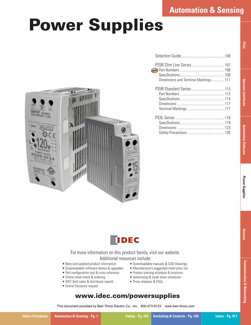
Table of Contents Automation & Sensing - Pg. 1 Safety - Pg. 315 Switching & Controls - Pg. 439 Index - Pg. 911
For more information on this product family, visit our website. Additional resources include:
• New and updated product information • Downloadable software demos & upgrades • Part confi guration tool & cross reference • Online stock check & ordering • IDEC fi eld sales & distributor search • Online literature request
• Downloadable manuals & CAD drawings • Manufacturer’s suggested retail price list • Product training schedule & locations • Advertising & trade show schedules • Press releases & FAQs
PLC
sO
perator InterfacesA
utomation S
oftware
Pow
er Supplies
Sensors
Com
munication &
Netw
orking
Automation & Sensing
Power Supplies
www.idec.com/powersupplies
Selection Guide ........................................... 106
PS5R Slim Line Series ................................ 107Part Numbers .................................................108Specifi cations .................................................109Dimensions and Terminal Markings ..............111
PS5R Standard Series ................................. 113Part Numbers .................................................113Specifi cations .................................................114Dimensions ....................................................117Terminal Markings .........................................117
PS3L Series ................................................ 118Specifi cations .................................................119Dimensions ...................................................123Safety Precautions .........................................126
NEW
This document provided by Barr-Thorp Electric Co., Inc. 800-473-9123 www.barr-thorp.com
Selection Guide
106 www.idec.com
PLC
sO
pera
tor
Inte
rfac
esA
utom
atio
n S
oftw
are
Pow
er S
uppl
ies
Sen
sors
Com
mun
icat
ion
& N
etw
orki
ng
Power SuppliesSelection Guide
Selection Guide
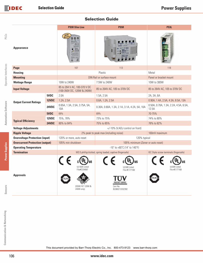
PS5R Slim Line PS5R PS3L
Appearance
Page 107 113 118
Housing Plastic Metal
Mounting DIN Rail or surface mount Panel or bracket mount
Wattage Range 10W to 240W 7.5W to 240W 10W to 300W
Input Voltage85 to 264 V AC, 100-370 V DC (100-350V DC, 120W & 240W)
85 to 264V AC, 105 to 370V DC 85 to 264V AC, 105 to 370V DC
Output Current Ratings
5VDC 2.0A 1.5A, 2.5A 2A, 3A, 6A
12VDC 1.2A, 2.5A 0.6A, 1.2A, 2.5A 0.90A, 1.4A, 2.5A, 4.3A, 8.5A, 13A
24VDC0.65A, 1.3A, 2.5A, 3.75A, 5A, 10A
0.30A, 0.60A, 1.3A, 2.1A, 3.1A, 4.2A, 5A, 10A0.50A, 0.70A, 1.3A, 2.2A, 4.5A, 6.5A, 12.5A
5VDC 69% 69% 70-75%
Typical Effi ciency 12VDC 75%, 78% 73% to 75% 74% to 80%
24VDC 80% to 84% 75% to 85% 78% to 82%
Voltage Adjustments +/-10% (V.ADJ control on front)
Ripple Voltage 2% peak to peak max (including noise) 160mV maximum
Overvoltage Protection (input) 120% or more, auto reset 120% typical
Overcurrent Protection (output) 105% min shutdown 105% minimum (Zener or auto reset)
Operating Temperature -10˚ to +60˚C (14˚ to 140˚F)
Termination M3.5 phillip/slotted, spring loaded, captive (fi ngersafe) IEC Style screw terminals (fi ngersafe)
Approvals
UL1604 ListedFile#E234997
(SEMI F47 120W & 240W only)
UL508 ListedFile #E177168
Cert No.BL980213332392
UL508 ListedFile #E177168
NEWModels
This document provided by Barr-Thorp Electric Co., Inc. 800-473-9123 www.barr-thorp.com
PS5R Slim Line Series
107USA: 800-262-IDEC Canada: 888-317-IDEC
PLC
sO
perator InterfacesA
utomation S
oftware
Pow
er Supplies
Sensors
Com
munication &
Netw
orking
Power Supplies
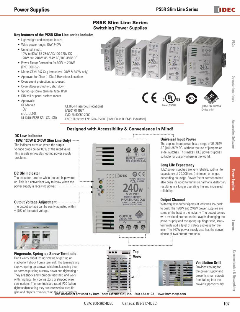
PS5R Slim Line Series Switching Power Supplies
Power Supplies
File #E234997 (SEMI F47 120W & 240W only)
Designed with Accessibility & Convenience in Mind!
DC Low Indicator (15W, 120W & 240W Slim Line Only)The indicator turns on when the output voltage drops below 80% of the rated value. This assists in troubleshooting power supply problems.
DC ON IndicatorThe indicator turns on when the unit is powered up. This is a convenient way to know when the power supply is receiving power.
Output Voltage AdjustmentThe output voltage can be easily adjusted within + 10% of the rated voltage.
Fingersafe, Spring-up Screw TerminalsDon’t worry about losing screws or getting an inadvertent shock from a terminal. The terminals are captive spring-up screws, which makes using them as easy as pushing a screw down and tightening it. They are shock and vibration resistant, and work with ring lugs, fork connectors or stripped wire connections. The terminals are rated IP20 (when tightened) meaning they are recessed to keep fi n-gers and objects from touching the input contacts.
Top View
Universal Input PowerThe applied input power has a range of 85-264V AC (100-350V DC) without the use of jumpers or slide switches. This makes IDEC power supplies suitable for use anywhere in the world.
Output ChannelWith very low output ripples of less than 1% peak to peak, the 120W and 240W power supplies are some of the best in the industry. The output comes with overload protection that avoids damaging the power supply and the spring-up, fi ngersafe, screw terminals add a level of safety and ease for the user. The 240W power supply also has the conve-nience of two output terminals.
Ventilation GrillProvides cooling for the power supply and prevents small objects from falling into the power supply circuitry.
Long Life ExpectancyIDEC power supplies are very reliable, with a life expectancy of 70,000 hrs. (minimum) or longer, depending on usage. Power factor correction has also been included to minimize harmonic distortion, resulting in a longer operating life and increased reliability.
Key features of the PS5R Slim Line series include:Lightweight and compact in size
Wide power range: 10W-240W
Universal input: 10W to 90W: 85-264V AC/100-370V DC120W and 240W: 85-264V AC/100-350V DC
Power Factor Correction for 60W to 240W (EN61000-3-2)
Meets SEMI F47 Sag Immunity (120W & 240W only)
Approved for Class 1, Div. 2 Hazardous Locations
Overcurrent protection, auto-reset
Overvoltage protection, shut down
Spring-up screw terminal type, IP20
DIN rail or panel surface mount
Approvals:CE MarkedTÜVc-UL, UL508UL1310 (PS5R-SB, -SC, -SD)
•
•
•
•
•
•
•
•
•
•
•
UL1604 (Hazardous locations)EN50178:1997LVD: EN60950:2000EMC: Directive EN61204-3:2000 (EMI: Class B, EMS: Industrial)
This document provided by Barr-Thorp Electric Co., Inc. 800-473-9123 www.barr-thorp.com

PS5R Slim Line Series
108 www.idec.com
PLC
sO
pera
tor
Inte
rfac
esA
utom
atio
n S
oftw
are
Pow
er S
uppl
ies
Sen
sors
Com
mun
icat
ion
& N
etw
orki
ng
Power Supplies
Item WattsRated Voltage
Rated Current
Part Number
10 5V DC 2.0A PS5R-SB05
15
12V DC 1.2A PS5R-SB12
24V DC 0.65A PS5R-SB24
30
12V DC 2.5A PS5R-SC12
24V DC 1.3A PS5R-SC24
60 24V DC 2.5A PS5R-SD24
Item WattsRated Voltage
Rated Current
Part Number
90 24V DC 3.75A PS5R-SE24
120 24V DC 5A PS5R-SF24
240 24V DC 10A PS5R-SG24
Part Numbers
Accessories
Appearance Description Part Number
Panel Mounting Bracket for PS5R-SB PS9Z-5R1B
Panel Mounting Bracket for PS5R-SB (fl at side mounting) PS9Z-5R2B
Panel Mounting Bracket for PS5R-SC and PS5R-SD PS9Z-5R1C
Panel Mounting Bracket for PS5R-SE PS9Z-5R1E
Panel Mounting Bracket for PS5R-SF & PS5R-SG PS9Z-5R1G
DIN rail (1000mm) BNDN1000
DIN rail end clip BNL5
This document provided by Barr-Thorp Electric Co., Inc. 800-473-9123 www.barr-thorp.com

PS5R Slim Line Series
109USA: 800-262-IDEC Canada: 888-317-IDEC
PLC
sO
perator InterfacesA
utomation S
oftware
Pow
er Supplies
Sensors
Com
munication &
Netw
orking
Power Supplies
Specifi cations
PartNumbers
5V DC output PS5R-SB05 – – – – –
12V DC output PS5R-SB12 PS5R-SC12 – – – –
24V DC output PS5R-SB24 PS5R-SC24 PS5R-SD24 PS5R-SE24 PS5R-SF24 PS5R-SG24
Output Capacity 15W (5V Model is 10W) 30W 60W 90W 120W 240W
Inpu
t
Input Voltage (single-phase, 2-wire)
85 to 264V AC,100 to 370V DC
85 to 264V AC,100 to 350V DC
Input Current (maximum)
100VAC 0.45A 0.9A 1.7A 2.3A 1.8A 3.5A
200VAC 0.3A 0.6A 1.0A 1.4A 1.0A 1.7A
Internal Fuse Rating 2A 3.15A 4A 6.3A
Inrush Current (cold start) 50A maximum (at 200V AC)
Leakage Current (at no load)132V AC: 0.38 mA maximum264V AC: 0.75 mA maximum
0.75mA maximum 1mA maximum
TypicalEffi ciency
5V DC 69% – – – – –
12V DC 75% 78% – – – –
24V DC 79% 80% 83% 82% 84%
Out
put
Output Current Ratings
5V DC 2.0A – – – – –
12V DC 1.2A 2.5A – – – –
24V DC 0.65A 1.3A 2.5A 3.75A 5A 10A
Voltage Adjustment ±10% (V. ADJ control on front)
Output Holding Time 20ms minimum (at rated input and output)
Starting Time 200ms maximum – – – 650ms maximum 500ms maximum
Rise Time 100ms maximum (at rated input and output) 200ms maximum
Line Regulation 0.4% maximum
Load Regulation 1.5% maximum 0.8% max
Temperature Regulation 0.05% degree C maximum
Ripple Voltage 2% peak to peak maximum (including noise) 1% peak to peak maximum (including noise)
Overcurrent Protection 105% or more, auto reset 105 to 130%, auto reset 103 to 110%, auto reset
Overvoltage Protection 120% min. SHUTDOWN
Operation Indicator LED (green)
Voltage Low Indication LED (amber) – – – LED (amber)
Dielectric StrengthBetween Input and Ground: 2000 V AC, 1 minuteBetween input and output: 3000V AC, 1 minute;Between output and ground: 500V AC, 1 minute.
Insulation Resistance Between Input & Output Terminals: 100 MΩ Min
Operating Temperature –10 to +65°C (14 to 149°F) -10 to 60°C (14 to 140°F)
Storage Temperature -25 to 75°C (-13 to +167°F)
Operating Humidity 20 to 90% relative humidity (no condensation)
Vibration Resistance Frequency 10 to 55Hz, Amplitude 0.375mm
Shock Resistance 300m/s2 (30G) 3 times each in 6 axes
ApprovalsEMC: EN61204-3 (EMI: Class B, EMS: Industrial), c-UL (CSA 22.2 No. 14), UL1604, UL508, LVD: EN60950, EN50178
UL1310 Class 2, c-UL (CSA 22.2 No. 213 and 223) – SEMI F47
Harmonic Directive N/A EN61000-3-2 A14 class A
Weight (approx.) 160g 250g 285g 440g 630g 1000g
Terminal Screw M3.5 slotted-Phillips head screw (screw terminal type)
IP protection IP20 fi ngersafe
Dimensions H x W x D (mm) 90 x 22.5 x 95 95 x 36 x 108 115 x 46 x 121 115 x 50 x 129 125 x 80 x 149.5
Dimensions H x W x D (inches) 3.54 x 0.89 x 3.74 3.74 x 1.42 x 4.25 4.53 x 1.81 x 4.76 4.53 x 1.97 x 5.08 4.92 x 3.15 x 5.891. For dimensions, see page 111.
This document provided by Barr-Thorp Electric Co., Inc. 800-473-9123 www.barr-thorp.com

PS5R Slim Line Series
110 www.idec.com
PLC
sO
pera
tor
Inte
rfac
esA
utom
atio
n S
oftw
are
Pow
er S
uppl
ies
Sen
sors
Com
mun
icat
ion
& N
etw
orki
ng
Power Supplies
Temperature Derating Curves
All IDEC Slim Line power supplies are listed to UL508, which allows operation at 100% capacity inside a panel. This eliminates the need to use oversize power supplies or utilize two power supplies derated at 50% of their rated output.
The charts below show that the PS5R Slim 10W (at 60ºC) and 15W (at 60ºC), 30W/60W/90W (at 55ºC), 120W (at 40ºC), and 240W (at 45ºC) meet the elevat-ed, ambient operating temperature required by UL508 and EN60950 standards to operate at an output current of 100%. The output current starts to derate beyond the required temperature.
55 -10 0 10 20 30 40 50 60 70 0
10 20 30 40
50 60 70 80 90
100
Ambient Operating Temperature (ºC)
O
utpu
t Cuu
rent
(%)
PS5R-SC
-10 0 10 20 30 40 50 60 70 0
10 20 30 40
50 60 70 80 90
100
Ambient Operating Temperature (ºC)
O
utpu
t Cuu
rent
(%)
PS5R-SD, -SE, -SF
45 -10 0 10 20 30 40 50 60 70 0
10 20 30 40
50 60 70 80 90
100
Ambient Operating Temperature (ºC)
O
utpu
t Cuu
rent
(%)
PS5R-SG
–10 0 10 20 30 40 50 60 6555 700
1020304050607080
90
100
Out
put C
urre
nt (%
)
Ambient Operating Temperature (°C)
Mounting A
Mounting B, C, D
PS5R-SB
Dearting curve for PS5R-SB varies depending on mounting method (see right).
Overload protection prevents the power supply from being damaged when an overload occurs. There are two kinds of protection.
Overvoltage Protection
Overvoltage ProtectionWhen the output voltage of the power supply rises to 120% or more of the rated value, the output will shut off. To restore power, only manual reset is avail-able which is an advantage in troubleshooting.
Overcurrent ProtectionPS5R-SF, -SG
Overcurrent ProtectionWhen the output current exceeds 105% of the rated current, overload protection is triggered, and the output voltage starts decreasing. When the output current returns within the rated range, the overload protection function is automatically cleared.
24
Overload Protection
SEMI-F47 Approved
The SEMI F47 (Semiconductor Processing Equipment Voltage Sag Im-munity) defi nes the minimum voltage sag ride-through requirements for semiconductor processing, automated test equipment, and other equipment. It requires that the equipment be able to tolerate voltage sags on an AC power line without interrupting operations. This avoids the loss of production and money.
The graph shows how the equipment must tolerate sags to 50% for 200ms, sags to 70% for up to 0.5 seconds, and sags to 80% for up to 1 second.Voltage Sag Sliding Scale
PS5R-SF, -SG
PS5R-SE 90W/3.75A/24V DC versus a Leading Competitor
Leading Competitor“24V/2.5A”
1.0
2.0
3.0
4.0
Curr
rent
(A)
“Normal” Rating 2.5A
“Boost” Rating 3.75A
Standard derating curve (operating temperature vs. output current)
Don’t Believe the HypeOther companies use slick marketing to sell you 60W power supplies with a “BOOST,” but what they don’t tell you is that these are merely 90W power supplies that have been renamed to fool you into thinking they have a unique feature. IDEC 90W power supplies are just what they claim, 90W power supplies. The truth is IDEC led the market by incorporating UL508 DIN rail mount power supplies as a standard product. Don’t let the other guys pull a fast one on you by claiming to provide features that just aren’t true, or even possible. See what IDEC has to offer, no strings attached.
Mounting A (standard)
Mounting B (upright)
Mounting C (left side up)
Mounting D (right side up)
This document provided by Barr-Thorp Electric Co., Inc. 800-473-9123 www.barr-thorp.com

PS5R Slim Line Series
111USA: 800-262-IDEC Canada: 888-317-IDEC
PLC
sO
perator InterfacesA
utomation S
oftware
Pow
er Supplies
Sensors
Com
munication &
Netw
orking
Power Supplies
Dimensions and Terminal Markings
PS5R-SB PS5R-SCPS5R-SD
PS5R-SE
PS5R-SF PS5R-SG
LINPUT 50/60Hz
VR.ADJ
DC ON
N
-V
OUTPUT
+V
LINPUT 50/60Hz
VR.ADJ
DC ON
N
-V
OUTPUT
+V
Height 95.0mmWidth 36.0mmDepth 108.0mm
Height 90mmWidth 22.5mm Depth 95mm
Height 115.0mmWidth 46.0mmDepth 121.0mm
Height 115.0mmWidth 50.0mmDepth 129.0mm
Height 125.0 mmWidth 80.0 mmDepth 149.5 mm
Front Panel (terminals)
Markings Name Description
V. ADJ Voltage adjustmentAdjusts within ±10%; turn clockwise to increase output voltage.
DC ON Operation indicator Green LED is lit when output voltage is on.
DC Low Output indicatorAmber LED is lit when output voltage drops below 80% of rated voltage.
+V, –V DC output terminals+V: Positive output Terminal–V: Negative output terminal
Frame groundGround this terminal to reduce high-frequency noise caused by switching power supply.
L, N Input terminalsAccept a wide range of voltages and frequen-cies (no polarity at DC input).
100-240VAC
INPUT
VR.ADJ
ON
LOW
OUTPUT
This document provided by Barr-Thorp Electric Co., Inc. 800-473-9123 www.barr-thorp.com

PS5R Slim Line Series
112 www.idec.com
PLC
sO
pera
tor
Inte
rfac
esA
utom
atio
n S
oftw
are
Pow
er S
uppl
ies
Sen
sors
Com
mun
icat
ion
& N
etw
orki
ng
Power Supplies
Mounting Bracket Dimensions (mm)
PS9Z-5R1B (for PS5R-SB) PS9Z-5R1C (for PS5R-SC & PS5R-SD)
2-M4 tapped holes or 2-ø4.5 through holes
1224.7
120
112
PS9Z-5R1B
115
105
2638
2-M4 Tapped Holes or2-ø4.5 Drilled Holes
PS9Z-5R1G (for PS5R-SF & PS5R-SG)PS9Z-5R1E (for PS5R-SE)
3648
135
125
2-M4 Tapped Holes or2-ø4.5 Drilled Holes
135
145
48
36
4-M4 Tapped Holes or4-ø4.5 Drilled Holes
PS9Z-5R2B (for PS5R-SB)
2-M4 tapped holes or 2-ø4.5 through holes
102
110
62.9
44
(See the front page for mounting examples.)
PS9Z-5R2B
This document provided by Barr-Thorp Electric Co., Inc. 800-473-9123 www.barr-thorp.com

PS5R Standard Series
113USA: 800-262-IDEC Canada: 888-317-IDEC
PLC
sO
perator InterfacesA
utomation S
oftware
Pow
er Supplies
Sensors
Com
munication &
Netw
orking
Power Supplies
PS5R Standard SeriesSwitching Power Supplies
Key features of the PS5R standard series include:Wide power range: 7.5W-240W
Universal input :7.5W-50W: 85-264V AC/105-370V DC100W: 85-132V AC/170-264V AC 240-370V DC (selectable) 75W, 120W, 240W: 85-264V AC/110-350V DC
Overcurrent/overvoltage protection
Power Factor Correction (75W, 120W, 240W models) EN61000-3-3 EN61000-3-2
Voltage adjustment +10%
Spring-up crew terminal, IP20 (fi nger-safe)
DIN rail or panel surface mount
Approvals: CE marked UL 508 Listed UL, c-UL TÜV approved EMC Directives: EN50081-2 EN50082-2 EN61000-6-2 LVD EN60950:2000
•
•
•
•
•
•
•
•
Item WattsRated Voltage
Rated Current
Part Number
7.5
5V DC 1.5A PS5R-A05
12V DC 0.6A PS5R-A12
24V DC 0.3A PS5R-A24
15
5V DC 2.5A PS5R-B05
12V DC 1.2A PS5R-B12
24V DC 0.6A PS5R-B24
30
12V DC 2.5A PS5R-C12
24V DC 1.3A PS5R-C24
50 24V DC 2.1A PS5R-D24
Item WattsRated Voltage
Rated Current
Part Number
75 24V DC 3.1A PS5R-Q24
100 24V DC 4.2A PS5R-E24
120 24V DC 5A PS5R-F24
240 24V DC 10A PS5R-G24
Part Numbers
UL 508 ListedFile #E177168
Cert No.BL980213332392
This document provided by Barr-Thorp Electric Co., Inc. 800-473-9123 www.barr-thorp.com

PS5R Standard Series
114 www.idec.com
PLC
sO
pera
tor
Inte
rfac
esA
utom
atio
n S
oftw
are
Pow
er S
uppl
ies
Sen
sors
Com
mun
icat
ion
& N
etw
orki
ng
Power Supplies
Specifi cations
PartNumbers
PS5R-A05 PS5R-B05* — — — —
PS5R-A12 PS5R-B12 PS5R-C12 — — —
PS5R-A24 PS5R-B24 PS5R-C24 PS5R-D24 PS5R-Q24 PS5R-E24 PS5R-F24 PS5R-G24
Output Capacity 7.5W 15W 30W 50W 75W 100W 120W 240W
Inpu
t
Input Voltage (single-phase, 2-wire)
100 to 240V AC nominal (85 to 264V AC), 50/60Hz (47 to 63Hz)110 to 340V DC nominal (105 to 370V DC)
100 to 120V AC, 50/60Hz200 to 240V AC, 50/60Hz (jumper selectable)240 to 370V DC
100 to 240V AC, 50/60Hz, 110 to 340V DC
Input Current (typical)0.17A at 100V AC
0.3A at 100V AC
0.68A at 100V AC
1.15A at 100V AC
1.1A at 100V AC
2.5A at 100V AC1.5A at 200V AC
1.8A at 100V AC
4A at 100V AC
Internal Fuse Rating 2A 2A 3.15A 3.15A 3.15A 4A 4A 6.3A
Inrush Current 50A maximum (at cold start at 200V AC)70A maximum (at cold start at 230V AC)
50A maximum (at cold start at 200V AC)
70A maximum (at cold start at 230V AC)
Leakage Current (at no load)
0.75mA maximum (60Hz, measured in conformance with UL, CSA, VDE)
Typical Effi ciency69% at 5V
75% at 12V79% at 24V
75% at 12V75% at 24V
79% at 24V 83% at 24V 85% at 24V 83% at 24V
Overvoltage Protection Outputs turns off at 105% (typical)
Out
put
Voltage and Current Ratings
5V, 1.5A12V, 0.6A24V, 0.3A
5V, 2.5A12V, 1.2A24V, 0.6A
12V, 2.5A24V, 1.3A
24V, 2.1A 24V, 3.1A 24V, 4.2A 24V, 5A 24V, 10A
Voltage Adjustments ±10% (V.ADJ screw on top)
Output Holding Time 20ms minimum (at full rated input and output)
Rise Time 200ms maximum (at full rated input and output) 150ms max.
Line Regulation 0.4% maximum
Load Regulation 1.5% maximum
Fluctuation due to Ambient Temperature Change
0.05% maximum
Ripple Voltage 2% peak to peak maximum (including noise)
Overload Protection 120% typical (Zener-limiting) 120% typical, auto reset
Operation Indicator LED (green)
Parallel Operation Allowed
PS5R-A PS5R-B PS5R-C PS5R-D PS5R-Q PS5R-E PS5R-F PS5R-G
No Yes No Yes
Dielectric StrengthBetween input and output terminals: 3,000V AC, 1 minute
Between input terminals and housing: 2,000V AC, 1 minuteBetween output terminal and housing: 500V AC, 1 minute
Insulation Resistance Between input and output terminals/input terminals and housing: 100MΩ minimum (500V DC megger)
Operating Temperature –10˚ to +60˚C (14˚ to 140˚F) (see derating curves)
Storage Temperature –30˚ to +85˚C (-22˚ to 185˚F)
Operating Humidity 20 to 90% relative humidity (no condensation)
Vibration Resistance 45m/s2, 10 to 55Hz, 2 hours on each of 3 axes 10 to 50Hz, 0.75mm p-p, 2 hrs on each of 3 axes
Shock Resistance 300m/s2 (30G), 3 shocks in each of 6 directions
ApprovalsConforms to EMC Directives EN50081-2 & EN50082-2. LVD Directive EN60529 — Certifi ed to EN60950.
UL508 listed. UL, c-UL, TUV approved. CE marked. EN61000-3-2
Weight 150g 170g 360g 390g 800g 600g 1200g 2000g
Termination Spring-up, fi ngersafe terminals with captive M3.5 screws
IP protection IP20 (fi nger safe)
Dimensions H x W x D (mm) 75 x 45 x 70 75 x 45 x95 75 x 90 x 95 75 x 90 x 95 120 x 85 x 140 75 x 145 x 95 120 x 115 x140 120 x 200x 140
Dimensions H x W x D (inches)
2.95 x 1.77 x 2.76
2.95 x 1.77 x 3.74
2.95 x 3.54 x 3.74
2.95 x 3.54 x 3.74
4.72 x 3.35 x 5.52
2.95 x 5.71 x 3.744.72 x 4.53 x 5.52
4.72 x 7.87 x 5.51
1. For dimensions, see page 117.2. For usage instructions, see page 116.3. *12.5W for 5VDC model. This document provided by Barr-Thorp Electric Co., Inc. 800-473-9123 www.barr-thorp.com

PS5R Standard Series
115USA: 800-262-IDEC Canada: 888-317-IDEC
PLC
sO
perator InterfacesA
utomation S
oftware
Pow
er Supplies
Sensors
Com
munication &
Netw
orking
Power Supplies
Temperature Derating Curves
A Mounting (standard)
Vertical
B Mounting (Facing Upward)
Vertical
0
10
20
30
40
50
60
70
80
90
100
0 10 20 30 40 50 60–10
Out
put C
urre
nt (
%)
Ambient Temperature (°C)
Mounting style B
Mounting style A
0
10
20
30
40
50
60
70
80
90
100
0 10 20 30 40 50 60–10 35
Out
put C
urre
nt (
%)
Ambient Temperature (°C)
Mounting style B
Mounting style A
0
10
20
30
40
50
60
70
80
90
100
0 10 20 30 40 50 60-10
Mounting style B
Mounting style A
Out
put C
urre
nt (
%)
Ambient Temperature (°C)
0
10
20
30
40
50
60
70
80
90
100
0 10 20 30 40 50 60
Operating Temperature (°C)
Out
put C
urre
nt (
%)
Mounting style BMouting style A
0
10
20
30
40
50
60
70
80
90
100
0 10 20 30 40 50 60
Operating Temperature (°C)
Mounting Style B
35
Mounting Style A
Out
put C
urre
nt (
%)
PS5R-A/B PS5R-C/D
PS5R-E PS5R-Q
PS5R-F/G
This document provided by Barr-Thorp Electric Co., Inc. 800-473-9123 www.barr-thorp.com

PS5R Standard Series
116 www.idec.com
PLC
sO
pera
tor
Inte
rfac
esA
utom
atio
n S
oftw
are
Pow
er S
uppl
ies
Sen
sors
Com
mun
icat
ion
& N
etw
orki
ng
Power Supplies
Accessories
Part Numbers: PS5R Accessories
Appearance Description Part Number
DIN rail (1000mm) BNDN1000
DIN rail end clip BNL5
Overcurrent Protection Characteristics
PS5R-A/B
100
50
0100105
Out
put V
olta
ge (
%)
Output Current (%)
PS5R-C/D/E
100
50
0100 105
Out
put V
olta
ge (
%)
Output Current (%)
Parallel Operation
+-
PS5R
PS5R
PS5R
PS5R
PS5R
TER
MIN
ALS
ELEC
TRIC
AL
LOA
D
1. Parallel operation only recommended for PS5R-Q24, PS5R-F24 and PS5R-G24. 2. Factory recommended diode ST Microelectronics BYV54V-50, BYV54V-100,
BYV54V-200, BYV541V-200 or with equivalent electrical specifi cations.3. Using the voltage adjustment make sure out-voltage is the same for all power
supplies.
Installation Instructions
Time-Saving Spring-up TerminalsThe innovative terminals on the PS5R series use a special, spring-loaded screw. This makes installation as easy as pushing down and turning with a screwdriver. Installation time is cut in half since the screws do not need to be backed out to install wiring. The screws are held captive once installed and are 100% fi nger-safe. Screw terminals accept bare wire or ring or fork connectors.
1. Insert the wire connector into the slot on the side of the power supply.
2. Using a fl at head or Phillips screwdriver, push down and turn the screw.
The wire is now connected, and the screw terminal is fi nger-safe!
Front Panel (terminals)
Markings Name Description
V. ADJVoltageadjustment
Adjusts within ±10%; turn clockwise to increase output voltage
DC ONOperation indicator
Green LED is lit when output voltage is on
+V, –VDC outputterminals
+V: Positive output Terminal–V: Negative output terminal
Frameground
Ground this terminal to reduce high-frequency currents caused by switching
L, NInput terminals
Accept a wide range of voltages and frequencies (no polarity at DC input)
NC No connectionDo not insert wires here, as this may damage the power supply
This document provided by Barr-Thorp Electric Co., Inc. 800-473-9123 www.barr-thorp.com

PS5R Standard Series
117USA: 800-262-IDEC Canada: 888-317-IDEC
PLC
sO
perator InterfacesA
utomation S
oftware
Pow
er Supplies
Sensors
Com
munication &
Netw
orking
Power Supplies
Dimensions
131313
85
120
101
60
512
135145
75
4-ø4.
5200-240V 200
102
4.613 26 131313
V.ADJ
DC ON
M3.5 TerminalScrews
10-ø6.54-ø4.5
8013131313
90
12
7.35
75605
V.ADJ
DC ON
M3.5 Terminal Screws
6062.5
3538.5
7.35
75
6-ø6
.5
R2.25
12
16 13131313
115
120
101
M3.5 TerminalScrews
M3.5 Terminal Screws
M3.5 TerminalScrews
V.ADJ
DC ON
M3.5 TerminalScrews
10-ø6.54-ø4.5
12
8013131313
90 7.35
75605
V.ADJ
DC ON
M3.5 TerminalScrews
6062.5
3538.5
7.35
75
6-ø6
.5
R2.25
12
4-ø4.5
110
754-ø4.5 105
110
120
4-ø4.5
110
190M3.5 TerminalScrews
14-ø
6.5
PS5R-A (7.5W) PS5R-B (15W) PS5R-C (30W)
PS5R-D (50W) PS5R-Q (75W) PS5R-F (120W)
PS5R-E (100W) PS5R-G (240W)
Terminal Markings
NC-V +V
V.ADJ
DC ON
NL
INPUT
NC–V +V
V.ADJ
DC ON
NLNC NC
INPUT
200-240V
–V +V
NL 200-240V 100-120VVOLTAGE SELECTINPUT
V.ADJ
DC ON 100w-OUTPUT
PS5R-A/B PS5R-C/D/Q/F/G PS5R-E
Height 75.0mmWidth 45.0mmDepth 70.0mm
Height 75.0mmWidth 45.0mmDepth 95.0mm
Height 75.0mmWidth 90.0mmDepth 95.0mm
Height 75.0mmWidth 90.0mmDepth 95.0mm
Height 120.0mmWidth 85.0mmDepth 140.0mm
Height 120.0mmWidth 115.0mmDepth 140.0mm
Height 120.0mmWidth 115.0mmDepth 140.0mm
Height 120.0mmWidth 200.0mmDepth 140.0mm
This document provided by Barr-Thorp Electric Co., Inc. 800-473-9123 www.barr-thorp.com

PS3L Series
118 www.idec.com
PLC
sO
pera
tor
Inte
rfac
esA
utom
atio
n S
oftw
are
Pow
er S
uppl
ies
Sen
sors
Com
mun
icat
ion
& N
etw
orki
ng
Power Supplies
PS3L Series Metal Frame Switching Power Supplies
Key features of the PS3L series include:Metal frame
Wide power range: 10W-300W
Universal input: 10W-30W: 85-264V AC/105-370V DC50W-300W: 85-264V AC/105-350V DC
Screw terminals, IP20 (fi ngersafe)
Power Factor Protection EN61000-3-2 EN61000-3-3 (50W to 300W models)
Overcurrent/overvoltage protection
Voltage +10% adjustment
DIN rail or panel surface mount
Approvals:CE markedUL508 listedEN50178 compliantEMC Directives EN50081-2 EN61000-6-2 LVD EN60950:2000
•
•
•
•
•
•
•
•
•UL508 ListedFile #E177168
Item WattsRated Voltage
Rated Current
Part Number
10
5V DC 2A PS3L-A05AFF
12V DC 0.9A PS3L-A12AFF
24V DC 0.5A PS3L-A24AFF
15
5V DC 3A PS3L-B05AFF
12V DC 1.4A PS3L-B12AFF
24V DC 0.7A PS3L-B24AFF
30
5V DC 6A PS3L-C05AFF
12V DC 2.5A PS3L-C12AFF
24V DC 1.3A PS3L-C24AFF
50
12V DC 4.3A PS3L-D12AFF
24V DC 2.2A PS3L-D24AFF
Item WattsRated Voltage
Rated Current
Part Number
100
12V DC 8.5A PS3L-E12AFF
24V DC 4.5A PS3L-E24AFF
150
12V DC 13A PS3L-F12AFF
24V DC 6.5A PS3L-F24AFF
300 24V DC 12.5A PS3L-G24AFF
This document provided by Barr-Thorp Electric Co., Inc. 800-473-9123 www.barr-thorp.com

PS3L Series
119USA: 800-262-IDEC Canada: 888-317-IDEC
PLC
sO
perator InterfacesA
utomation S
oftware
Pow
er Supplies
Sensors
Com
munication &
Netw
orking
Power Supplies
Specifi cations
TypePS3L-A(10W)
PS3L-B(15W)
PS3L-C(30W)
PS3L-D(50W)
PS3L-E(100W)
PS3L-F(150W)
PS3L-G24(300W)
Inpu
t
Input Voltage(Single-phase two-wire)
100 to 240V AC(Voltage range: 85 to 264V AC/105 to 370V DC)
100 to 240V AC(Voltage range: 85 to 264V AC/105 to 350V DC)
Frequency (AC input only) 47 to 63Hz
Input Current(Typical)
100V 0.25A 0.37A 0.68A 0.68A 1.4A 2.0A 3.8A
200V 0.16A 0.23A 0.45A 0.34A 0.65A 0.95A 2.0A
Inrush Current (Cold start)
100V 20A max. 20A max. 20A max. 30A max. 30A max. 30A max. 30A max.
200V 40A max. 40A max. 40A max. 60A max. 60A max. 60A max. 60A max.
Leakage Current 0.75 mA max. (60Hz; UL, CSA, VDE)
Power Factor (Typical) — 0.99 (100V AC input, rated output), 0.95 (200V AC, rated output)
Effi ciency (Typical) 5V DC: 70%12V DC: 74%24V DC: 78%
5V DC: 73%12V DC: 75%24V DC: 78%
5V DC: 75%12V DC: 77%24V DC: 79%
—12V DC: 76%24V DC: 79%
—12V DC: 78%24V DC: 81%
—12V DC: 80%24V DC: 83%
——24V DC: 81%
Out
put
Rated Voltage/Current 5V/2A12V/0.9A24V/0.5A
5V/3A12V/1.4A24V/0.7A
5V/6A12V/2.5A24V/1.3A
—12V/4.3A24V/2.2A
—12V/8.5A24V/4.5A
—12V/13A24V/6.5A
——24V/12.5A
Adjustable Voltage Range ±10% (V.ADJ control on front)
Output Holding Time 20msec minimum (at the rated input and output)
Start Time 200msec maximum (at the rated input and output) 500msec maximum (at the rated input and output)
Rise Time 100msec maximum (at the rated input and output) 200msec maximum (at the rated input and output)
Reg
ulat
ion
Input Fluctuation 5V: 20mV maximum, 12V: 48mV maximum, 24V: 96mV maximum
Load Fluctuation 5V: 40mV maximum, 12V: 100mV maximum, 24V: 150mV maximum
Temperature Change(–10 to +50°C)
5V 50mV maximum12V: 120mV maximum24V: 240mV maximum
5V: 60mV maximum12V: 150mV maximum24V: 290mV maximum
Ripple Voltage
–10 to 0°C 5V: 160mV maximum, 12V/24V: 180mV maximum 1 200 mV maximum 1
0 to +50°C 5V: 120mV maximum, 12V/24V: 150mV maximum 1
Sup
plem
enta
ryFu
ncti
ons
Overcurrent Protection 105% (Typical), Automatic reset 2
Overvoltage Protection 120% min. 3 Output off at 120%, reset when input voltage is restored. 4
Operation Indicator LED (green)
Dielectric StrengthBetween input and output terminals: 3,000V AC, 1 minuteBetween input terminal and housing: 2,000V AC, 1 minuteBetween output terminal and housing: 500V AC, 1 minute
Insulation ResistanceBetween input and output terminals: 100MW minimum (500V DC megger)Between input terminal and housing: 100MW minimum (500V DC megger)
Operating Temperature 5 –10˚ to +70°C –10˚ to +60°C –10˚ to +65°C
Storage Temperature –30° to +75°C
Operating Humidity 20 to 90% RH (no condensation, no freezing)
Vibration Resistance 10 to 55Hz, 20m/s2 constant, sweep cycle 1 minute, 2 hours each in 3 axes
Shock Resistance 200m/s2, 11ms, 1 shock each in 3 axes
Dimensions H X W X D (mm) 97 x 35 x 86 97 x 35 x 86 96 x 35 x 114.5 97 x 37 x 147.5 97 x 54 x 200 97 x 62 x 200 158 x 63 x 230
Weight (Approx.) 240g 250g 340g 350g 630g 730g 1550g
Terminal Screw M4 slotted-Phillips head screw (screw terminal type)
1. Including noise. Measured at the terminal block according to EIAJ.2. Protection against short-circuit and overcurrent of 30 seconds maximum. Overload for 30 seconds or longer
may damage the internal elements.3. Zener limiter method4. Turn the input off and after one minute, turn the input on again.5. Refer to the derating characteristics. No freezing. The maximum temperature is the temperature at 100%
output current (natural air-cooling) in the derating characteristics.
This document provided by Barr-Thorp Electric Co., Inc. 800-473-9123 www.barr-thorp.com
PS3L Series
120 www.idec.com
PLC
sO
pera
tor
Inte
rfac
esA
utom
atio
n S
oftw
are
Pow
er S
uppl
ies
Sen
sors
Com
mun
icat
ion
& N
etw
orki
ng
Power Supplies
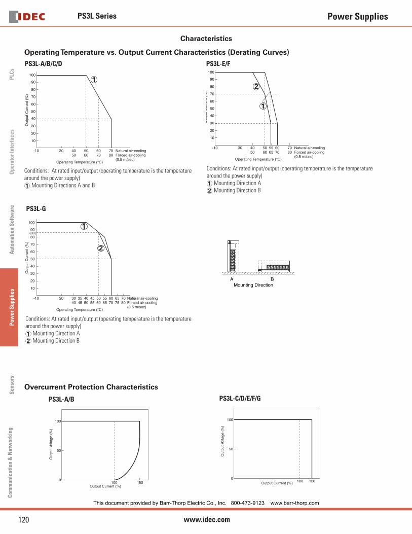
Characteristics
Operating Temperature vs. Output Current Characteristics (Derating Curves)
AMounting Direction
B
30 40 50 60 7050 60 70 80
Natural air-coolingForced air-cooling(0.5 m/sec)
-10
10
20
30
40
50
60
70
80
90
100
Operating Temperature (°C)
Out
put C
urre
nt (
%)
1
PS3L-A/B/C/D
Conditions: At rated input/output (operating temperature is the temperature around the power supply)1 Mounting Directions A and B
30 40 50 60 7050 60
5565 70 80
-10
10
20
30
40
50
60
70
80
90
100
Natural air-coolingForced air-cooling(0.5 m/sec)
Operating Temperature (°C)
Out
put C
urre
nt (
%)
1
2
PS3L-E/F
Conditions: At rated input/output (operating temperature is the temperature around the power supply)1 Mounting Direction A2 Mounting Direction B
20 30 40 50 6040
3545 50
4555 60
5565 70
6575
7080
-10
10
20
30
40
50
60
70
80
90(88)
100
Natural air-coolingForced air-cooling(0.5 m/sec)
Operating Temperature (°C)
Out
put C
urre
nt (
%)
1
2
PS3L-G
Conditions: At rated input/output (operating temperature is the temperature around the power supply)1 Mounting Direction A2 Mounting Direction B
Overcurrent Protection Characteristics
100
50
0100 150
Output Current (%)
Out
put V
olta
ge (
%)
100
50
0100 120Output Current (%)
Out
put V
olta
ge (
%)
PS3L-A/B PS3L-C/D/E/F/G
This document provided by Barr-Thorp Electric Co., Inc. 800-473-9123 www.barr-thorp.com

PS3L Series
121USA: 800-262-IDEC Canada: 888-317-IDEC
PLC
sO
perator InterfacesA
utomation S
oftware
Pow
er Supplies
Sensors
Com
munication &
Netw
orking
Power Supplies
Terminal Markings
LEDV.ADJ
+V
-V
AC(L)
AC(N)
PS3L-G
+V
-V
AC(L)
AC(N)
LEDV.ADJ
PS3L-E/F
LEDV.ADJ
+V
-V
AC(L)
AC(N)
+V
-V
AC(L)
AC(N)
LEDV.ADJ
PS3L-A/B PS3L-C/D
Marking Name Description
V.ADJ Output Voltage AdjustmentAllows adjustment within ±10%. Turning clockwise increases the output voltage.
LED Operation Indicator (Green) Lights when the output voltage is on.
+V–V
DC Output Terminals+V: Positive output terminal–V: Negative output terminal
Ground TerminalGrounding the terminal reduces high-frequency currents caused by switching.
AC Input TerminalAccepts a wide range of voltage and frequency. Polarity is irrelevant when using a DC input.
This document provided by Barr-Thorp Electric Co., Inc. 800-473-9123 www.barr-thorp.com

PS3L Series
122 www.idec.com
PLC
sO
pera
tor
Inte
rfac
esA
utom
atio
n S
oftw
are
Pow
er S
uppl
ies
Sen
sors
Com
mun
icat
ion
& N
etw
orki
ng
Power Supplies
Accessories
Mounting Bracket (Optional)
Model Mounting Plate L-shaped Bracket (wide) L-shaped Bracket (narrow) Dimensions
PS3L-A/B PS9Z-3E1B PS9Z-3E2B PS9Z-3E3B
See page 124
PS3L-C PS9Z-3E1C PS9Z-3E2C PS9Z-3E3C
PS3L-D PS9Z-3E1D PS9Z-3E2D PS9Z-3E3D
PS3L-E PS9Z-3L1F PS9Z-3E2E PS9Z-3E3E
PS3L-F PS9Z-3L1F PS9Z-3E2F PS9Z-3E3F
PS3L-G PS9Z-3L1G — —
DIN-Rail Mounting Bracket (Optional)
Model Part Number
PS3L-A
PS9Z-3E4CPS3L-B
PS3L-C
PS3L-D PS9Z-3E4D
PS3L-EPS9Z-3E4F
PS3L-FDIN-rail mounting brackets are ordered separately from
switching power supplies.
DIN-Rail Mounting Bracket DimensionsPart Number Model L1 (mm) L2 (mm) L3 (mm) H1 (mm) H2 (mm)
PS9Z-3E4C
PS3L-A
134117 35 5.2 20.8
PS3L-B
PS3L-C 156 35 5.2 20.8
PS9Z-3E4D PS3L-D 186 178.8 39.5 5.2 20.8
PS9Z-3E4FPS3L-E
216.8 230.8 65 11.2 20PS3L-F
35 L1
L2
97
H1
35H
2
DIN Rail (Optional)
Part Number Length Material
BNDN1000 1000 mm Aluminum
A
C
Overall length 39.4" (1000mm)
K
F
HGB D
H
Length in Inches (mm)
A 1.4” (35mm)
B 1.14” (29mm)
C 0.78” (23mm)
D 1.2” (31mm)
F 0.11” (3mm)
G 2” (51mm)
H 0.47” (12mm)
K 0.16” (4mm)
End Clip (Optional)
9mm wide
Item Package No.
DIN Rail End Clip BNL5
This document provided by Barr-Thorp Electric Co., Inc. 800-473-9123 www.barr-thorp.com

PS3L Series
123USA: 800-262-IDEC Canada: 888-317-IDEC
PLC
sO
perator InterfacesA
utomation S
oftware
Pow
er Supplies
Sensors
Com
munication &
Netw
orking
Power Supplies
Dimensions (tolerance ±1mm)
2-M3 (Depth: 6 mm max.)
2-M3 (Depth: 6 mm max.)
LEDV.ADJ
85±0
.597
16 45±0.586
6
7 74±0.5
17.5
35
Height 97.0mmWidth 35.0mmDepth 86.0mm
PS3L-A/B (10/15W)
2-M3 (Depth: 6 mm max.)V.ADJ
LED
55±0
.55.
596
114.5
2-M3 (Depth: 6 mm max.)
17.5
35
83±0.518.5
50±0.540
Height 96.0mmWidth 35.0mmDepth 114.5mm
PS3L-C (30W)
V.ADJ 3-M3 (Depth: 6 mm max.)LED
29.5 112±0.5147.5
97
63±0
.5
46±0
.517
20±0
.5
3-M3 (Depth: 6 mm max.)
37
21.5
127±0.512.5
Height 97.0mmWidth 37.0mmDepth 147.5mm
PS3L-D (50W)
5-M4 (Depth: 6 mm max.)
V.ADJ
25±0
.5
29.5
LED
±0.5
127±0.5
2754
200
97
Height 97.0mmWidth 54.0mmDepth 200.0mm
PS3L-E (100W)
25±0
.5
5-M4 (Depth: 6 mm max.)
V.ADJLED
±0.5
3262
97
200
29.5
Height 97.0mmWidth 62.0mmDepth 200.0mm
PS3L-F (150W)25
±0.5
4-M4 (Depth: 6 mm max.)
V.ADJ
6.5 200±0.5
2463
158
230
LED Height 158.0mmWidth 63.0mmDepth 230.0mm
PS3L-G (300W)
This document provided by Barr-Thorp Electric Co., Inc. 800-473-9123 www.barr-thorp.com
PS3L Series
124 www.idec.com
PLC
sO
pera
tor
Inte
rfac
esA
utom
atio
n S
oftw
are
Pow
er S
uppl
ies
Sen
sors
Com
mun
icat
ion
& N
etw
orki
ng
Power Supplies
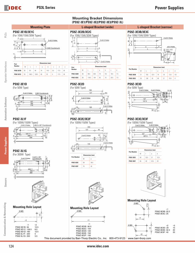
Mounting Bracket Dimensions (PS9Z-3E1/PS9Z-3E2/PS9Z-3E3/PS9Z-3L)
Mounting Plate L-shaped Bracket (wide) L-shaped Bracket (narrow)
PS9Z-3E1B/3E1C(For 10W/15W/30W Types)
2-ø3.5 Holes
2-M3 Countersunk
c
b a
l
de
2 L
W
Part Number
Dimensions (mm)
W L l a b c d e
PS9Z-3E1B 35 101 94 74 14.5 3.5 17.5 30
PS9Z-3E1C 33 138.5 128.5 83 32 5 17.5 26
PS9Z-3E2B/3E2C(For 10W/15W/30W Types)
2-ø3.5 Holes
2-ø3.5 HolescW
baL
dl
2
815
Part Number
Dimensions (mm)
W L l a b c d
PS9Z-3E2B 36 95.5 80.5 74 9.5 18.5 7.5
PS9Z-3E2C 38 118.5 104 83 15 20.5 7.5
PS9Z-3E3B/3E3C(For 10W/15W/30W Types)
2-ø3.5 Holes
ø3.5 Holes
3.5 × 4.5 Hole∗
W2.
3
a bL
d l
6.5
17.5
28
c
Part NumberDimensions (mm)
W L l a b c d
PS9Z-3E3B 31 103 22.5 74 18 13.5 4.5
PS9Z-3E3C 33 126 25 83 21 15.5 4
PS9Z-3E1D(For 50W Type)
3-M3 Countersunk2-ø4.5 Holes
24 1275 160
170
29.5
2
17 20
18 34.5
PS9Z-3E2D(For 50W Type)
2-ø4.5 Holes
3-ø3.5 Holes
150
9.5127
15 120
29 20
44.5
1020
2.3
PS9Z-3E3D(For 50W Type)
3-ø3.5 Holes
1015
.5
20 34.5
127 18157.5
10
2
4-ø4.5 Holes
7.5 15
28
10 20
PS9Z-3L1F(For 100W/150W Types)
44.5 1275 220
230
±0.2
±0.2
362
3125
±0.2
60
2-ø4.5 Holes 3-ø8.5 x 90° Countersunk
PS9Z-3L1G(For 300W Type)
3-ø8.5 x 90° Countersunk2-ø4.5 Holes
21.5 2005 250
±0.2
±0.2
260
352
31.5
2425
±0.2
63
Mounting Hole Layout2-M3
∗1
∗2
∗1PS9Z-3E1B: �94PS9Z-3E1C:�128.5PS9Z-3E1D:�160PS9Z-3L1F:�220PS9Z-3L1G:�250
∗212.58.512.553.5
PS9Z-3E2E/3E2F(For 100W/150W Types)
2-ø4.5 Holes
3-ø4.5 Holes
200
127 46
25 150
a25
W
1020
2.3
Part NumberDimensions (mm)
W a
PS9Z-3E2E 59 34.5
PS9Z-3E2F 70 40
Mounting Hole Layout2-M3
∗1
PS9Z-3E2B:�80.5PS9Z-3E2C:�104PS9Z-3E2D:�120PS9Z-3E2E:�150PS9Z-3E2F :�150
∗1
PS9Z-3E3E/3E3F(For 100W/150W Types)
4-ø5.5 Holes3-ø4.5 Holes
2-C2
10a 25 W
127 53.5207.5
10 2037.5
10
2
bl
Part NumberDimensions (mm)
W l a b
PS9Z-3E3E 54 32.5 27 12.5
PS9Z-3E3F 65 40 32.5 20
Mounting Hole Layout
4-M4
∗2
∗3
2-M3
∗1
17.5
� ∗1PS9Z-3E3B:�22.5PS9Z-3E3C:�25
� ∗2PS9Z-3E3D: �20PS9Z-3E3E: �32.5PS9Z-3E3F: �40
∗3152020
This document provided by Barr-Thorp Electric Co., Inc. 800-473-9123 www.barr-thorp.com

PS3L Series
125USA: 800-262-IDEC Canada: 888-317-IDEC
PLC
sO
perator InterfacesA
utomation S
oftware
Pow
er Supplies
Sensors
Com
munication &
Netw
orking
Power Supplies
Direct Mount Installation
PS3L-A/B PS3L-C PS3L-D
A 2-M3 (Depth: 6 mm max.)
B 2-M3 (Depth: 6 mm max.)
A 2-M3 (Depth: 6 mm max.)
B 2-M3 (Depth: 6 mm max.)
A 3-M3(Depth: 6 mm max.)
B 3-M3(Depth: 6 mm max.)
PS3L-E/F PS3L-G
A 2-M4(Depth: 6 mm max.)
B 3-M4 (Depth: 6 mm max.)
4-M4 (Depth: 6 mm max.)B
4-M4(Depth: 6 mm max.)
A
The fi gures above show the frames only. PC board and parts are omitted for illustration purposes.Mounting screws NOT supplied with power supplies.
InstallationMounting Hole Layout
PS3L-A/B PS3L-C PS3L-D PS3L-E/F PS3L-G
A Side Mounting(screw from the back)
2-ø4 Holes
45
85
2-ø4 Holes
50
55
3-ø4 Holes
112
63
29
2-ø5 Holes
127
18.5
207
10612
5
4-ø5 Holes
B Side Mounting(screw from the back)
2-ø4 Holes
74
2-ø4 Holes
83
3-ø4 Holes
127
20 3-ø5 Holes
127(or 100)
25
200
25
4-ø5 Holes
This document provided by Barr-Thorp Electric Co., Inc. 800-473-9123 www.barr-thorp.com
PS3L Series
126 www.idec.com
PLC
sO
pera
tor
Inte
rfac
esA
utom
atio
n S
oftw
are
Pow
er S
uppl
ies
Sen
sors
Com
mun
icat
ion
& N
etw
orki
ng
Power Supplies
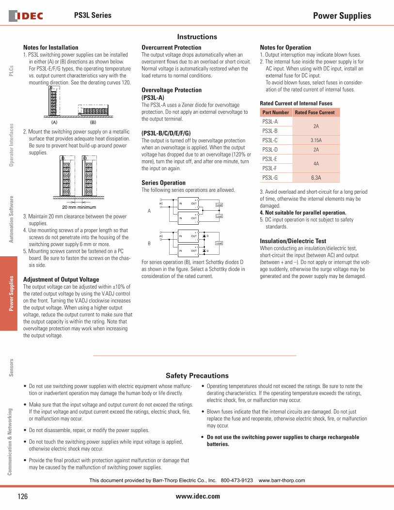
InstructionsNotes for Installation1. PS3L switching power supplies can be installed
in either (A) or (B) directions as shown below. For PS3L-E/F/G types, the operating temperature vs. output current characteristics vary with the mounting direction. See the derating curves 120.
(A) (B)
2. Mount the switching power supply on a metallic surface that provides adequate heat dissipation. Be sure to prevent heat build-up around power supplies.
20 mm minimum
3. Maintain 20 mm clearance between the power supplies.
4. Use mounting screws of a proper length so that screws do not penetrate into the housing of the switching power supply 6 mm or more.
5. Mounting screws cannot be fastened on a PC board. Be sure to fasten the screws on the chas-sis side.
Adjustment of Output VoltageThe output voltage can be adjusted within ±10% of the rated output voltage by using the V.ADJ control on the front. Turning the V.ADJ clockwise increases the output voltage. When using a higher output voltage, reduce the output current to make sure that the output capacity is within the rating. Note that overvoltage protection may work when increasing the output voltage.
Overcurrent ProtectionThe output voltage drops automatically when an overcurrent fl ows due to an overload or short circuit. Normal voltage is automatically restored when the load returns to normal conditions.
Overvoltage Protection(PS3L-A)The PS3L-A uses a Zener diode for overvoltage protection. Do not apply an external overvoltage to the output terminal.
(PS3L-B/C/D/E/F/G)The output is turned off by overvoltage protection when an overvoltage is applied. When the output voltage has dropped due to an overvoltage (120% or more), turn the input off, and after one minute, turn the input on again.
Series OperationThe following series operations are allowed.
A
+
-INAC OUT
+
-IN OUT
Load
Load
B
+
-INAC OUT
+
-IN OUT
Load
D
D
For series operation (B), insert Schottky diodes D as shown in the fi gure. Select a Schottky diode in consideration of the rated current.
Notes for Operation1. Output interruption may indicate blown fuses. 2. The internal fuse inside the power supply is for
AC input. When using with DC input, install an external fuse for DC input.
To avoid blown fuses, select fuses in consider-ation of the rated current of internal fuses.
Rated Current of Internal Fuses
Part Number Rated Fuse Current
PS3L-A2A
PS3L-B
PS3L-C 3.15A
PS3L-D 2A
PS3L-E4A
PS3L-F
PS3L-G 6.3A
3. Avoid overload and short-circuit for a long period of time, otherwise the internal elements may be damaged.4. Not suitable for parallel operation.5. DC input operation is not subject to safety
standards.
Insulation/Dielectric TestWhen conducting an insulation/dielectric test, short-circuit the input (between AC) and output (between + and –). Do not apply or interrupt the volt-age suddenly, otherwise the surge voltage may be generated and the power supply may be damaged.
Safety PrecautionsDo not use switching power supplies with electric equipment whose malfunc-tion or inadvertent operation may damage the human body or life directly.
Make sure that the input voltage and output current do not exceed the ratings. If the input voltage and output current exceed the ratings, electric shock, fi re, or malfunction may occur.
Do not disassemble, repair, or modify the power supplies.
Do not touch the switching power supplies while input voltage is applied, otherwise electric shock may occur.
Provide the fi nal product with protection against malfunction or damage that may be caused by the malfunction of switching power supplies.
•
•
•
•
•
Operating temperatures should not exceed the ratings. Be sure to note the derating characteristics. If the operating temperature exceeds the ratings, electric shock, fi re, or malfunction may occur.
Blown fuses indicate that the internal circuits are damaged. Do not just replace the fuse and reoperate, otherwise electric shock, fi re, or malfunction may occur.
Do not use the switching power supplies to charge rechargeable batteries.
•
•
•
This document provided by Barr-Thorp Electric Co., Inc. 800-473-9123 www.barr-thorp.com