
Power Sulfur Area Materials of Construction - Brimstone · PDF fileHydrogen Induced Cracking /...
76
Sulfur Area Materials of Construction Infrastructure Federal Industrial & Commercial Power Jacquelyn A. Carioscia Johnny E. Johnson Richard J. Wissbaum URS Energy & Construction
Transcript of Power Sulfur Area Materials of Construction - Brimstone · PDF fileHydrogen Induced Cracking /...

Sulfur Area Materials of Construction
Infrastructure Federal Industrial & CommercialPower
Jacquelyn A. Carioscia
Johnny E. Johnson
Richard J. Wissbaum
URS Energy & Construction
POWER INFRASTRUCTURE FEDERAL INDUSTRIAL & COMMERCIAL
2011 Brimstone Sulfur Symposium, Vail CO
Objectives
1. To facilitate an open discussion of common corrosion issues encountered in the industry today.
2. To improve understanding of the causes of corrosion and means to mitigate corrosion.
3. To capture – to the greatest extent possible – typical industry practice currently used in the design and construction of sulfur processing facilities.
4. Your active participation is vital to achieving these objectives.
Our goal is to provide the facility engineer with enough knowledge to oversee the design process and to alert operating personnel to practices and procedures which will maximize the
life of sulfur processing facilities.
POWER INFRASTRUCTURE FEDERAL INDUSTRIAL & COMMERCIAL
2011 Brimstone Sulfur Symposium, Vail CO
Agenda
1. Review of corrosion mechanisms and corrosive environments which are common in sulfur processing facilities
2. Review of common materials of construction
3. Group discussion of corrosion “hotspots” identified by questionnaire responses
...all subject to the constraints of our allotted time!

POWER INFRASTRUCTURE FEDERAL INDUSTRIAL & COMMERCIAL
2011 Brimstone Sulfur Symposium, Vail CO
An Unusual Example of Erosion
Schedule 160 hydrogen pipe.

POWER INFRASTRUCTURE FEDERAL INDUSTRIAL & COMMERCIAL
2011 Brimstone Sulfur Symposium, Vail CO
An Unusual Example of Erosion
Stainless steel bolt and nut which attached an
instrument to a support stand.
Vibration from a reciprocating compressor
caused the pipe to repeatedly strike the bolt
and nut.
POWER INFRASTRUCTURE FEDERAL INDUSTRIAL & COMMERCIAL
2011 Brimstone Sulfur Symposium, Vail CO
Corrosion Mechanisms
POWER INFRASTRUCTURE FEDERAL INDUSTRIAL & COMMERCIAL
2011 Brimstone Sulfur Symposium, Vail CO
Sulfide Corrosion
• Hydrogen sulfide attacks carbon steel to from iron sulfide.
• Corrosion of carbon steels by sulfides (including H2S) in a hydrogen-free environment was studied by McConomy in 1963.
• Corrosion of carbon steels by H2S in a hydrogen environment was studied by Sharp and Haycock in 1959.- At temperatures below 650 °F and H2S partial pressures below 10 psi, the
corrosion rate is less than 50 mils/year
- However, the resulting sulfide scale is fairly impervious and resists further corrosion
POWER INFRASTRUCTURE FEDERAL INDUSTRIAL & COMMERCIAL
2011 Brimstone Sulfur Symposium, Vail CO
Corrosion/Erosion
• Hydrogen sulfide will corrode carbon steel to form an iron sulfide layer on the surface of the steel
• If undisturbed, this iron sulfide layer prevents further corrosion
• However, if the layer is disrupted mechanically, the underlying carbon steel is again exposed to corrosion. This can lead to very rapid corrosion rates
• The iron sulfide layer is not mechanically strong and can be disrupted:- Mechanically, for example, by high liquid velocities and/or turbulence in amine
systems
- Thermally, for example, by temperature cycles in sub-dewpoint Claus units leading to spalling of the sulfide scale
POWER INFRASTRUCTURE FEDERAL INDUSTRIAL & COMMERCIAL
2011 Brimstone Sulfur Symposium, Vail CO
Stress Corrosion Cracking
Stress Corrosion Cracking is a cracking process resulting from both:
• Action of a corrodent, and
• Sustained tensile stress, either the result of applied stress (e.g. internal pressure) or residual stress from manufacturing.
Potential corrodents of interest include:
• Amines
• Chlorides
• Hydrogen sulfide
High stress areas are most susceptible to cracking.
Steels with higher yield strengths are more susceptible to cracking.

POWER INFRASTRUCTURE FEDERAL INDUSTRIAL & COMMERCIAL
2011 Brimstone Sulfur Symposium, Vail CO
Alkaline Stress Corrosion Cracking
Alkaline SCC can be caused by amines, caustic, ammonia, etc.
• Carbon steels are susceptible to alkaline SCC.
• High temperatures increase the likelihood of cracking.
• Stronger bases increase the likelihood of cracking.

POWER INFRASTRUCTURE FEDERAL INDUSTRIAL & COMMERCIAL
2011 Brimstone Sulfur Symposium, Vail CO
Chloride Stress Corrosion Cracking
Another form of SCC is Chloride Stress Corrosion Cracking:
• Cracking of Austenitic stainless steels in the presence of chlorides
• Temperatures above 160°F increase likelihood of cracking
• Cracking can occur with very low chloride levels (~50 ppmw)
• Low pH increases risk
Chloride stress corrosion cracking (SCC) on the cooling water side of a 316L stainless steel exchanger tube. The cooling water
contained approximately 400 ppm chlorides had been blocked in with the 350F shellside process still flowing. The black stringers
are sulfide inclusions. 100X

POWER INFRASTRUCTURE FEDERAL INDUSTRIAL & COMMERCIAL
2011 Brimstone Sulfur Symposium, Vail CO
Sulfide Stress Cracking
By far, the most common form of SCC in sour environments.
• Occurs in the presence of a liquid water phase and hydrogen sulfide
• Reaction of H2S with iron at the surface of the steel:
Fe + H2S FeS + 2·H0
• The hydrogen atoms are free to dissolve into the steel, leading to embrittlement and possible cracking.

POWER INFRASTRUCTURE FEDERAL INDUSTRIAL & COMMERCIAL
2011 Brimstone Sulfur Symposium, Vail CO
Hydrogen Induced Cracking / Hydrogen Stress Cracking
Unlike SCC, Hydrogen Induced Cracking can occur in low stress areas.
• HIC affects only carbon steel plate; castings and forgings are not affected.
• Atomic hydrogen diffuses into the steel and accumulates at trap points by recombining into molecular hydrogen.
• Trap sites are commonly found in steels with (a) high impurity levels, or (b) a high density of planar inclusions, or (c) regions of anomalous microstructure.
Closely related is Hydrogen Stress Cracking:
• Caused by embrittlement of metal by diffused hydrogen in the presence of applied stress and galvanic coupling to another metal that is corroding as an anode.
POWER INFRASTRUCTURE FEDERAL INDUSTRIAL & COMMERCIAL
2011 Brimstone Sulfur Symposium, Vail CO
Ammonium Bisulfide Corrosion
• When significant amounts of ammonia are present in the water phase (for example, in a refinery sour water stripper) the pH increases, increasing the solubility of H2S and the concentration of the bisulfideion.
• The combination of high pH and high ammonium bisulfideconcentration leads to a high hydrogen flux rate high corrosion rates
• This is exacerbated by the presence of cyanides – cyanides poison the surface reaction that leads to formation of a stable iron sulfide protective coating

POWER INFRASTRUCTURE FEDERAL INDUSTRIAL & COMMERCIAL
2011 Brimstone Sulfur Symposium, Vail CO
Materials of Construction

POWER INFRASTRUCTURE FEDERAL INDUSTRIAL & COMMERCIAL
2011 Brimstone Sulfur Symposium, Vail CO
Carbon Steel
• Contains 0.10% – 0.31% maximum C and 0.85% – 1.2% Mn.
Carbon steel may be:
• ...Annealed by heating above the Austenite transition temperature followed by controlled cooling in the furnace to produce a softer, uniform steel;
• ...Normalized by heating above the transition temperature followed by air cooling to reduce internal stresses;
• ...Killed (or deoxidized) by addition of aluminum or other oxygen scavenger. SA-516 grades of carbon steel plate are killed; A-106 grade B carbon steel pipe is killed.
The fabricated equipment may be:
• ...Post-weld heat treated (or stress relieved) to eliminate residual stresses from fabrication.

POWER INFRASTRUCTURE FEDERAL INDUSTRIAL & COMMERCIAL
2011 Brimstone Sulfur Symposium, Vail CO
Austenitic Stainless Steel
• Addition of chrome and nickel to carbon steel prevents the phasetransformation from Austenite to ferrite / cementite on cooling.
• Generally requires about 18% chrome and 8% (and higher) nickel (the chrome content allows lower nickel content)
• Not susceptible to hydrogen cracking• Welding stainless steel can lead to sensitization – where carbon is
concentrated in the HAZ and can form Chromium carbide – leading to decrease corrosion resistance. The “L” grades of stainless steel have lower carbon content and are not easily sensitized.
• Very susceptible to chloride stress cracking- Significant increases in nickel content or addition of molybdenum reduces
susceptibility to chloride cracking (e.g. 316 SS contains 11% - 14% nickel and 2% molybdenum

POWER INFRASTRUCTURE FEDERAL INDUSTRIAL & COMMERCIAL
2011 Brimstone Sulfur Symposium, Vail CO
NACE MR0175 / ISO 15156-1
• First issued in 1975. Latest revision is dated 2009.• Addresses all cracking mechanisms caused by H2S including:
- Sulfide stress cracking (SSC)
- Stress corrosion cracking (SCC)
- Hydrogen induced cracking (HIC)
- Stress oriented hydrogen induced cracking (SOHIC)
- Soft zone cracking (SZC)
- Galvanically induced hydrogen stress cracking
• Applies to H2S-containing environments in oil and gas production and natural gas sweetening plants.
• “Not necessarily applicable” to refining or downstream processes and equipment.
• Part 2 specifies requirements for both carbon or low-alloy steels; part 3 specifies requirements for corrosion resistant alloys (CRAs)

POWER INFRASTRUCTURE FEDERAL INDUSTRIAL & COMMERCIAL
2011 Brimstone Sulfur Symposium, Vail CO
NACE MR0175 / ISO 15156-1
pH
PH2S (kPa)
100 kPa ≈ 15 psia

POWER INFRASTRUCTURE FEDERAL INDUSTRIAL & COMMERCIAL
2011 Brimstone Sulfur Symposium, Vail CO
NACE MR0175 / ISO 15156-1
Region 0 (pale green):
• No precautions are required; however, very high-strength steels (>140,000 psi) can crack in H2S-free aqueous environments
Region 3 (pale red):
• Carbon or low alloy steels must meet the requirements of A.2.
Region 2 (yellow):
• Carbon or low alloy steels must meet the requirements of A.3.
Region 1 (pale yellow):
• Carbon or low alloy steels must meet the requirements of A.4.
Note: Complying with the above does not necessarily provide protection against HIC, SOHIC, or SZC.

POWER INFRASTRUCTURE FEDERAL INDUSTRIAL & COMMERCIAL
2011 Brimstone Sulfur Symposium, Vail CO
NACE MR0103
• First issued in 2003. Latest revision is dated 2010.
• Establishes material requirements for resistance to sulfide stress cracking in sour petroleum refining environments containing H2S as a gas or dissolved in an aqueous phase, with or without the presence of hydrocarbon.
Differences between MR0103 and MR0175:
• Recognizes the impact caused by the presence of ammonia and cyanide in sour environments
• Does not address chloride stress cracking (a key difference from MR0175) because chloride concentrations tend to be lower in refineries.
• Recognizes that CO2, which tends to be lower in concentration in refineries, results in lower pH and mitigates hydrogen production and therefore cracking potential.

POWER INFRASTRUCTURE FEDERAL INDUSTRIAL & COMMERCIAL
2011 Brimstone Sulfur Symposium, Vail CO
NACE MR0103
Sour refinery environments consist of any of the following:
• More than 50 ppmw H2S in the aqueous phase, OR
• An aqueous phase pH less than 4 and some H2S present, OR
• An aqueous phase pH greater than 7.6 and more than 20 ppmw HCN concentration and some H2S present, OR
• A gas phase H2S partial pressure greater than 0.0003 MPa (0.05 psia) associated with an aqueous phase.

POWER INFRASTRUCTURE FEDERAL INDUSTRIAL & COMMERCIAL
2011 Brimstone Sulfur Symposium, Vail CO
Questions and Comments from the Survey

POWER INFRASTRUCTURE FEDERAL INDUSTRIAL & COMMERCIAL
2011 Brimstone Sulfur Symposium, Vail CO
Survey
1.Quench loop corrosion in piping such that we cannot make 5 year run. What metallurgy is typical on piping? PWHT? What design is used for caustic injection (or other chemistry)? What limits of operation (high/low pH) are used? What design is used for mix point of caustic/process? Background: We are experiencing accelerated corrosion here due to SO2 breakthrough and lack of hydrogen. We don’t add hydrogen (typically) because of excess hydrocarbons in our hydrogen. Can’t achieve >2% H2 at this point. Solution is to supply purchased (clean) H2 to the unit.
POWER INFRASTRUCTURE FEDERAL INDUSTRIAL & COMMERCIAL
2011 Brimstone Sulfur Symposium, Vail CO
Survey
2. TGU MDEA reboiler inlet. Regenerator is SS clad with SS internals; reboiler inlet piping is CS. After huge SO2breakthrough (not followed immediately by H2S-containing gas) lost half the wall thickness in days.

POWER INFRASTRUCTURE FEDERAL INDUSTRIAL & COMMERCIAL
2011 Brimstone Sulfur Symposium, Vail CO
Survey
3. Mixed metal exchanger bundles – Several locations purchased L/R exchanger bundles with SS tubes and CS tie rods, baffles, etc. We found several “cut” tubes or severely corroded tubes in proximity to where SS tubes contacted CS parts.

POWER INFRASTRUCTURE FEDERAL INDUSTRIAL & COMMERCIAL
2011 Brimstone Sulfur Symposium, Vail CO
Survey
4. Pitting on last sulfur condenser tubes (process side). Not a lot of details. We suspect some type of ammonia corrosion but mechanism unknown.

POWER INFRASTRUCTURE FEDERAL INDUSTRIAL & COMMERCIAL
2011 Brimstone Sulfur Symposium, Vail CO
Survey
5. Several locations have problems with acid gas reheaterburner corrosion. Most of them were due to carburization.

POWER INFRASTRUCTURE FEDERAL INDUSTRIAL & COMMERCIAL
2011 Brimstone Sulfur Symposium, Vail CO
Survey
6. Areas of most corrosion are in CS quench columns in amine-based tail gas units. This is from SO2breakthrough. Any new insights would be great.
POWER INFRASTRUCTURE FEDERAL INDUSTRIAL & COMMERCIAL
2011 Brimstone Sulfur Symposium, Vail CO
Survey
7. We had nozzles on our sulfur converters fail in about 18 months. The nozzles were not insulated.

POWER INFRASTRUCTURE FEDERAL INDUSTRIAL & COMMERCIAL
2011 Brimstone Sulfur Symposium, Vail CO
Survey
8. Thru-wall corrosion most prevalent in regions of low temperature such as piping to incinerator and sub-dewpoint units. Has also occurred in hotter zones like 1st condenser outlet piping. How best to repair without taking the unit down?
POWER INFRASTRUCTURE FEDERAL INDUSTRIAL & COMMERCIAL
2011 Brimstone Sulfur Symposium, Vail CO
Survey
9. Very severe corrosion of condenser tubes in the 1st condenser following an unexpected shutdown where no heat soak was performed.

POWER INFRASTRUCTURE FEDERAL INDUSTRIAL & COMMERCIAL
2011 Brimstone Sulfur Symposium, Vail CO
Survey
10. Corrosion in sulfur pits: (a) sulfur pit pumps, (b) sulfur pit steam coils, (c) sulfur pit concrete walls and support steel.

POWER INFRASTRUCTURE FEDERAL INDUSTRIAL & COMMERCIAL
2011 Brimstone Sulfur Symposium, Vail CO
Survey
11. Note that while it is well and good to discuss proper design and selection of materials, many of us have to live with what we have. Please discuss how to prevent or fix leaks in existing systems.

POWER INFRASTRUCTURE FEDERAL INDUSTRIAL & COMMERCIAL
2011 Brimstone Sulfur Symposium, Vail CO
Survey
12. Waste heat boiler tube to tubesheet joint issues with corrosion of tube ends and loss of joint integrity:
One company uses alonized tubes welded to the back side of the front tube sheet. Tubesheet has 1/8”stainless cladding and tube holes in tubesheet have a SS insert. 18 years of trouble-free operation at 500 psi.

POWER INFRASTRUCTURE FEDERAL INDUSTRIAL & COMMERCIAL
2011 Brimstone Sulfur Symposium, Vail CO
Survey
13. As SRU throughput increased over time, spot IR surveys showed WHB outlet line temperature increased to above 700 F. Had high corrosion rates on piping from WHB to 1st Condenser, in the 1st Condenser inlet channel and tube inlets. At shutdown, refractory lined the pipe and inlet channel and installed ceramic ferrules in condenser tube inlets.

POWER INFRASTRUCTURE FEDERAL INDUSTRIAL & COMMERCIAL
2011 Brimstone Sulfur Symposium, Vail CO
Specific Applications – Claus Sulfur Recovery

POWER INFRASTRUCTURE FEDERAL INDUSTRIAL & COMMERCIAL
2011 Brimstone Sulfur Symposium, Vail CO
38
Amine Acid Gas Piping
Process Conditions and Corrosion Mechanisms
• 100 – 120 °F and 20 – 25 psia
• H2S, CO2, trace NH3, H2O (V+L)
• Sulfide stress cracking, HIC (welded piping)
Corrosion Mitigation Strategies
• Use carbon steel with hardness control to avoid cracking
• No pockets to prevent liquid accumulation; consider tracing
Typical Industry Practice
• Design 300 °F and 50 psig (or match upstream equipment)
• A-106 Gr. B, 0.125” – 0.25” CA, NACE applies
POWER INFRASTRUCTURE FEDERAL INDUSTRIAL & COMMERCIAL
2011 Brimstone Sulfur Symposium, Vail CO
39
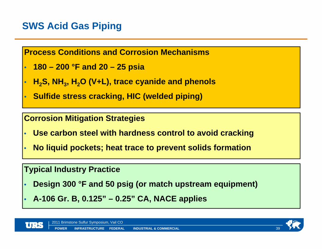
SWS Acid Gas Piping
Process Conditions and Corrosion Mechanisms
• 180 – 200 °F and 20 – 25 psia
• H2S, NH3, H2O (V+L), trace cyanide and phenols
• Sulfide stress cracking, HIC (welded piping)
Corrosion Mitigation Strategies
• Use carbon steel with hardness control to avoid cracking
• No liquid pockets; heat trace to prevent solids formation
Typical Industry Practice
• Design 300 °F and 50 psig (or match upstream equipment)
• A-106 Gr. B, 0.125” – 0.25” CA, NACE applies

POWER INFRASTRUCTURE FEDERAL INDUSTRIAL & COMMERCIAL
2011 Brimstone Sulfur Symposium, Vail CO
40
Acid Gas Knockout Drums
Process Conditions and Corrosion Mechanisms
• 100 – 120 °F and 20 – 25 psia
• H2S, CO2, trace NH3, H2O (V+L)
• Sulfide stress cracking, susceptible to HIC
Corrosion Mitigation Strategies
• Use carbon steel with hardness control to avoid cracking
• 304L SS cladding optional; consider heat tracing
Typical Industry Practice
• Design 300 °F and 50 psig (or match upstream equipment)
• SA-516-70, 0.125” – 0.25” CA, NACE applies
POWER INFRASTRUCTURE FEDERAL INDUSTRIAL & COMMERCIAL
2011 Brimstone Sulfur Symposium, Vail CO
41
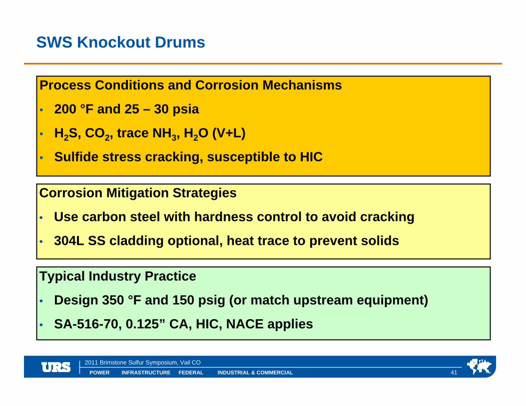
SWS Knockout Drums
Process Conditions and Corrosion Mechanisms
• 200 °F and 25 – 30 psia
• H2S, CO2, trace NH3, H2O (V+L)
• Sulfide stress cracking, susceptible to HIC
Corrosion Mitigation Strategies
• Use carbon steel with hardness control to avoid cracking
• 304L SS cladding optional, heat trace to prevent solids
Typical Industry Practice
• Design 350 °F and 150 psig (or match upstream equipment)
• SA-516-70, 0.125” CA, HIC, NACE applies

POWER INFRASTRUCTURE FEDERAL INDUSTRIAL & COMMERCIAL
2011 Brimstone Sulfur Symposium, Vail CO
42
SRU Reaction Furnace
Process Conditions and Corrosion Mechanisms
• Up to 2750 °F and 15 – 25 psia
• H2S, CO2, SO2, NH3, COS, CS2, H2O(V), elemental sulfur, reducing
• Sulfide corrosion (>650 °F); low temperature acid attack
Corrosion Mitigation Strategies
• Use CS and keep the shell temperature between 400 °F and 650 °F
• Internal refractory lining + external thermal shroud
Typical Industry Practice
• Design steel to 650 °F & 50 – 100 psig; refractory lined
• SA-516-70, 0.25” CA

POWER INFRASTRUCTURE FEDERAL INDUSTRIAL & COMMERCIAL
2011 Brimstone Sulfur Symposium, Vail CO
43
Claus Waste Heat Boiler (Process Side)
Process Conditions and Corrosion Mechanisms
• Up to 2750 °F and 15 – 25 psia
• H2S, CO2, SO2, NH3, COS, CS2, H2O(V), elemental sulfur, reducing
• Sulfide corrosion (>650 °F); low temperature acid attack
Corrosion Mitigation Strategies
• Use CS; keep the tube / tubesheet metal temperatures below 650 °F
• Refractory line tubesheet and provide ferrules
Typical Industry Practice
• Design steel to 650 °F and 50 – 100 psig; refractory lined as above
• Shell: SA-516-70, 0.25” CA; Tubes: SA-106 Gr. B Sch. 80

POWER INFRASTRUCTURE FEDERAL INDUSTRIAL & COMMERCIAL
2011 Brimstone Sulfur Symposium, Vail CO
44
Claus Condensers (Process Side)
Process Conditions and Corrosion Mechanisms
• 350 – 650 °F and 15 – 25 psia
• H2S, CO2, SO2, NH3, COS, CS2, H2O(V), elemental sulfur, reducing
• Sulfide corrosion (>650 °F); low temperature acid attack
Corrosion Mitigation Strategies
• Carbon steel construction is adequate
• Refractory line specific areas
Typical Industry Practice
• Design steel to 650 °F and 15 – 50 psig; refractory lined
• Shell: SA-516-70, 0.125” – 0.25” CA; Tubes: SA-179 0.134” wall

POWER INFRASTRUCTURE FEDERAL INDUSTRIAL & COMMERCIAL
2011 Brimstone Sulfur Symposium, Vail CO
45
Claus Steam Reheaters (Process Side)
Process Conditions and Corrosion Mechanisms
• 350 – 475 °F and 15 – 25 psia
• H2S, CO2, SO2, NH3, COS, CS2, H2O(V), elemental sulfur, reducing
• Sulfide corrosion (>650 °F); low temperature acid attack
Corrosion Mitigation Strategies
• Carbon steel construction is adequate
Typical Industry Practice
• Design 650 °F and 15 – 50 psig
• Shell: SA-516-70, 0.25” CA; Tubes: SA-179

POWER INFRASTRUCTURE FEDERAL INDUSTRIAL & COMMERCIAL
2011 Brimstone Sulfur Symposium, Vail CO
46
Claus Converters
Process Conditions and Corrosion Mechanisms
• Up to 475 – 650 °F and 15 – 25 psia
• H2S, CO2, SO2, NH3, COS, CS2, H2O(V), elemental sulfur, reducing
• Sulfide corrosion (>650 °F); low temperature acid attack
Corrosion Mitigation Strategies
• Carbon steel construction is adequate
• Provide refractory lining and full external insulation
Typical Industry Practice
• Design 650 °F and 15 – 50 psig; refractory lined
• SA-516-70, 0.125” – 0.25” CA; 304 removable SS internals
POWER INFRASTRUCTURE FEDERAL INDUSTRIAL & COMMERCIAL
2011 Brimstone Sulfur Symposium, Vail CO
47
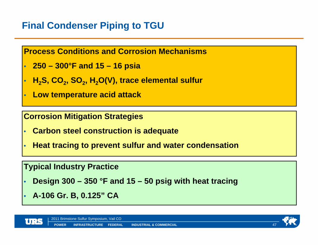
Final Condenser Piping to TGU
Process Conditions and Corrosion Mechanisms
• 250 – 300°F and 15 – 16 psia
• H2S, CO2, SO2, H2O(V), trace elemental sulfur
• Low temperature acid attack
Corrosion Mitigation Strategies
• Carbon steel construction is adequate
• Heat tracing to prevent sulfur and water condensation
Typical Industry Practice
• Design 300 – 350 °F and 15 – 50 psig with heat tracing
• A-106 Gr. B, 0.125” CA

POWER INFRASTRUCTURE FEDERAL INDUSTRIAL & COMMERCIAL
2011 Brimstone Sulfur Symposium, Vail CO
Specific Applications – Tail Gas Treating
POWER INFRASTRUCTURE FEDERAL INDUSTRIAL & COMMERCIAL
2011 Brimstone Sulfur Symposium, Vail CO
49
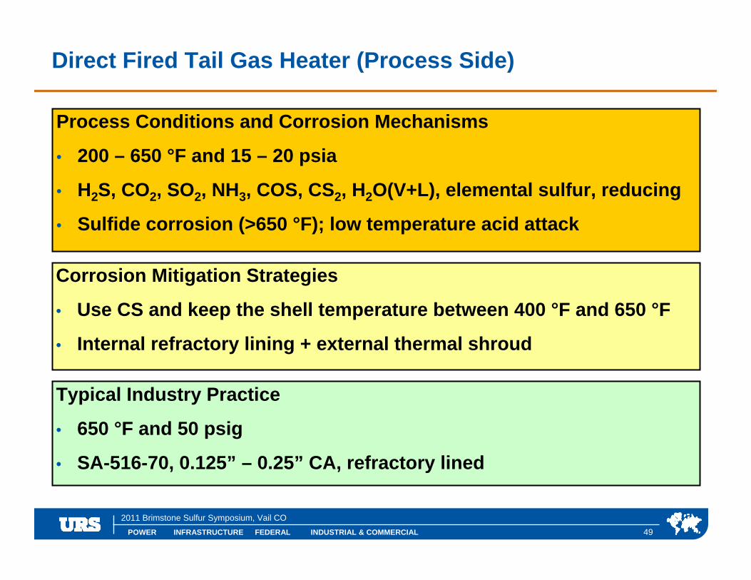
Direct Fired Tail Gas Heater (Process Side)
Process Conditions and Corrosion Mechanisms
• 200 – 650 °F and 15 – 20 psia
• H2S, CO2, SO2, NH3, COS, CS2, H2O(V+L), elemental sulfur, reducing
• Sulfide corrosion (>650 °F); low temperature acid attack
Corrosion Mitigation Strategies
• Use CS and keep the shell temperature between 400 °F and 650 °F
• Internal refractory lining + external thermal shroud
Typical Industry Practice
• 650 °F and 50 psig
• SA-516-70, 0.125” – 0.25” CA, refractory lined
POWER INFRASTRUCTURE FEDERAL INDUSTRIAL & COMMERCIAL
2011 Brimstone Sulfur Symposium, Vail CO
50
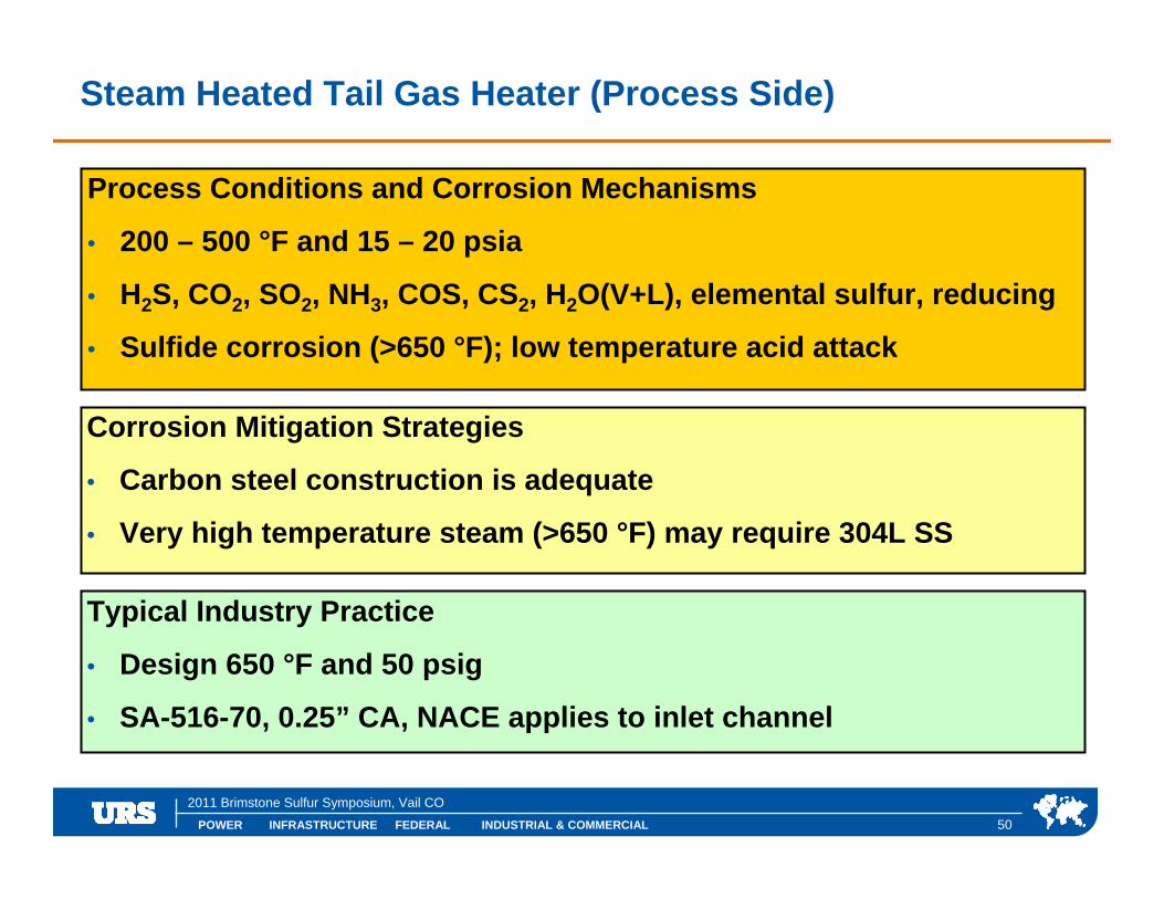
Steam Heated Tail Gas Heater (Process Side)
Process Conditions and Corrosion Mechanisms
• 200 – 500 °F and 15 – 20 psia
• H2S, CO2, SO2, NH3, COS, CS2, H2O(V+L), elemental sulfur, reducing
• Sulfide corrosion (>650 °F); low temperature acid attack
Corrosion Mitigation Strategies
• Carbon steel construction is adequate
• Very high temperature steam (>650 °F) may require 304L SS
Typical Industry Practice
• Design 650 °F and 50 psig
• SA-516-70, 0.25” CA, NACE applies to inlet channel
POWER INFRASTRUCTURE FEDERAL INDUSTRIAL & COMMERCIAL
2011 Brimstone Sulfur Symposium, Vail CO
51
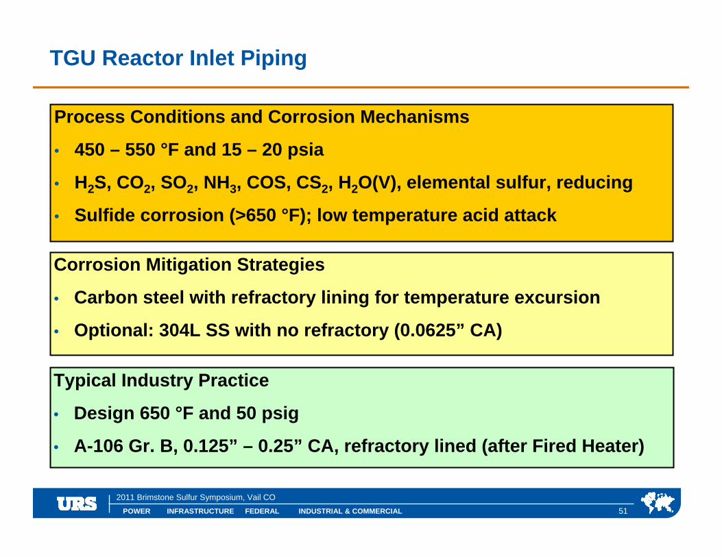
TGU Reactor Inlet Piping
Process Conditions and Corrosion Mechanisms
• 450 – 550 °F and 15 – 20 psia
• H2S, CO2, SO2, NH3, COS, CS2, H2O(V), elemental sulfur, reducing
• Sulfide corrosion (>650 °F); low temperature acid attack
Corrosion Mitigation Strategies
• Carbon steel with refractory lining for temperature excursion
• Optional: 304L SS with no refractory (0.0625” CA)
Typical Industry Practice
• Design 650 °F and 50 psig
• A-106 Gr. B, 0.125” – 0.25” CA, refractory lined (after Fired Heater)

POWER INFRASTRUCTURE FEDERAL INDUSTRIAL & COMMERCIAL
2011 Brimstone Sulfur Symposium, Vail CO
52
TGU Reactor
Process Conditions and Corrosion Mechanisms
• 540 – 650 °F and 15 – 20 psia
• H2S, CO2, SO2, NH3, COS, CS2, H2O(V), elemental sulfur, reducing
• Sulfide corrosion (>650 °F); low temperature acid attack
Corrosion Mitigation Strategies
• Carbon steel with refractory lining for temperature excursion
• Keep steel wall temperature between 350 – 650 °F
Typical Industry Practice
• Design 650 °F and 50 psig; refractory lined
• SA-516-70, 0.25” CA, 304 SS removable internals

POWER INFRASTRUCTURE FEDERAL INDUSTRIAL & COMMERCIAL
2011 Brimstone Sulfur Symposium, Vail CO
53
TGU Reactor Outlet Piping
Process Conditions and Corrosion Mechanisms
• 650 °F and 15 – 20 psia
• H2S, CO2, NH3, trace COS, H2O(V)
• Sulfide corrosion (>650 °F); low temperature acid attack
Corrosion Mitigation Strategies
• Carbon steel with refractory lining for temperature excursion
• Optional 1-¼ Cr, ½ Mo without refractory (A-335), 0.125” CA
Typical Industry Practice
• Design 650 °F and 50 psig
• A-106 Gr. B, 0.125” – 0.25” CA, refractory lined

POWER INFRASTRUCTURE FEDERAL INDUSTRIAL & COMMERCIAL
2011 Brimstone Sulfur Symposium, Vail CO
54
TGU Waste Heat Boiler (Process Side)
Process Conditions and Corrosion Mechanisms
• 650 °F and 15 – 20 psia
• H2S, CO2, NH3, trace COS, H2O(V)
• Sulfide corrosion (>650 °F); low temperature acid attack
Corrosion Mitigation Strategies
• Carbon steel construction is adequate
• Refractory lined inlet channel for temperature excursions
Typical Industry Practice
• Design 650 °F and 50 psig; refractory lined
• Shell: SA-516-70, 0.125” – 0.25” CA; Tubes: SA-179 0.134” wall

POWER INFRASTRUCTURE FEDERAL INDUSTRIAL & COMMERCIAL
2011 Brimstone Sulfur Symposium, Vail CO
55
Quench Tower
Process Conditions and Corrosion Mechanisms
• 100 – 350 °F and 15 – 20 psia
• H2S, CO2, NH3 or NaOH, trace COS, H2O(V)
• Sulfide stress cracking, acid corrosion, HIC
Corrosion Mitigation Strategies
• CS with hardness control is adequate; 304L SS is optional
• Caustic (or ammonia) injection for pH control
Typical Industry Practice
• Design 400 °F and 50 psig
• SA-516-70 + 0.25” CA, 304 SS internals , NACE applies

POWER INFRASTRUCTURE FEDERAL INDUSTRIAL & COMMERCIAL
2011 Brimstone Sulfur Symposium, Vail CO
56
Quench Water Pumps
Process Conditions and Corrosion Mechanisms
• 150 °F and 150 psia
• H2O(L), NH3 or NaOH, trace CO2 and H2S
• Sulfide stress cracking
Corrosion Mitigation Strategies
• Stainless steel construction
Typical Industry Practice
• Design 250 °F and 150 psig
• API A-8, 316SS case and impeller, NACE applies

POWER INFRASTRUCTURE FEDERAL INDUSTRIAL & COMMERCIAL
2011 Brimstone Sulfur Symposium, Vail CO
57
Quench Water Piping
Process Conditions and Corrosion Mechanisms
• 100 – 175 °F and <150 psia
• H2O(L), NH3 or NaOH, trace CO2 and H2S
• Sulfide stress cracking, acid corrosion
Corrosion Mitigation Strategies
• CS with hardness control is adequate; 304L SS is optional
• Caustic (or ammonia) injection for pH control
Typical Industry Practice
• Design 250 – 350 °F and 150 psig
• A-106 Gr. B, 0.125” – 0.25” CA, NACE applies

POWER INFRASTRUCTURE FEDERAL INDUSTRIAL & COMMERCIAL
2011 Brimstone Sulfur Symposium, Vail CO
58
Quench Water Filters
Process Conditions and Corrosion Mechanisms
• <150 °F and <150 psia
• H2O(L), NH3 or NaOH, trace CO2 and H2S
• Sulfide stress cracking, acdi corrosion, HIC
Corrosion Mitigation Strategies
• Carbon steel with hardness control
Typical Industry Practice
• Design 250 – 350 °F and 150 psig
• SA-516-70, 0.125” – 0.25” CA, NACE applies

POWER INFRASTRUCTURE FEDERAL INDUSTRIAL & COMMERCIAL
2011 Brimstone Sulfur Symposium, Vail CO
59
Quench Water Cooler, Water (Process Side) or Air-Cooled
Process Conditions and Corrosion Mechanisms
• 100 – 150 °F and 75 psia
• H2O(L), NH3 or NaOH, trace CO2 and H2S
• Sulfide stress cracking, alkaline stress cracking, acid corrosion, HIC
Corrosion Mitigation Strategies
• Carbon steel, Austenitic (304Lor 316L) Stainless Steel or more exotic
• Actual selection varies widely
Typical Industry Practice
• Design 250 °F and 150 psig
• NACE applies

POWER INFRASTRUCTURE FEDERAL INDUSTRIAL & COMMERCIAL
2011 Brimstone Sulfur Symposium, Vail CO
60
TGU Absorber
Process Conditions and Corrosion Mechanisms
• 100 – 120 °F and 15 – 16 psia
• H2O (V+L), CO2, H2S, trace COS, and amine
• Amine stress corrosion cracking, HIC
Corrosion Mitigation Strategies
• Carbon steel with hardness control; 304L SS cladding optional
Typical Industry Practice
• 200 – 250 °F and 50 psig
• SA-516-70, 0.125” – 0.25” CA, NACE applies
POWER INFRASTRUCTURE FEDERAL INDUSTRIAL & COMMERCIAL
2011 Brimstone Sulfur Symposium, Vail CO
61
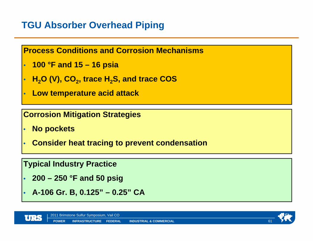
TGU Absorber Overhead Piping
Process Conditions and Corrosion Mechanisms
• 100 °F and 15 – 16 psia
• H2O (V), CO2, trace H2S, and trace COS
• Low temperature acid attack
Corrosion Mitigation Strategies
• No pockets
• Consider heat tracing to prevent condensation
Typical Industry Practice
• 200 – 250 °F and 50 psig
• A-106 Gr. B, 0.125” – 0.25” CA

POWER INFRASTRUCTURE FEDERAL INDUSTRIAL & COMMERCIAL
2011 Brimstone Sulfur Symposium, Vail CO
62
Incinerator Chamber
Process Conditions and Corrosion Mechanisms
• 1000 – 1800 °F and 16 psia
• H2O (V), CO2, H2S, SO2, and trace elemental sulfur
• High temperature sulfide attack, low temperature acid attack
Corrosion Mitigation Strategies
• Carbon steel is adequate
• Control shell temperature with refractory lining and thermal shield
Typical Industry Practice
• Design up to 1800 °F and 50 psig
• SA-516-70, 0.125” CA
POWER INFRASTRUCTURE FEDERAL INDUSTRIAL & COMMERCIAL
2011 Brimstone Sulfur Symposium, Vail CO
63
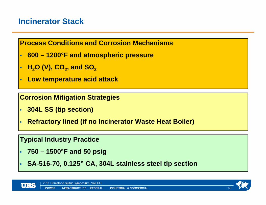
Incinerator Stack
Process Conditions and Corrosion Mechanisms
• 600 – 1200°F and atmospheric pressure
• H2O (V), CO2, and SO2
• Low temperature acid attack
Corrosion Mitigation Strategies
• 304L SS (tip section)
• Refractory lined (if no Incinerator Waste Heat Boiler)
Typical Industry Practice
• 750 – 1500°F and 50 psig
• SA-516-70, 0.125” CA, 304L stainless steel tip section

POWER INFRASTRUCTURE FEDERAL INDUSTRIAL & COMMERCIAL
2011 Brimstone Sulfur Symposium, Vail CO
Specific Applications – Sour Water Stripping

POWER INFRASTRUCTURE FEDERAL INDUSTRIAL & COMMERCIAL
2011 Brimstone Sulfur Symposium, Vail CO
General Discussion
• Refinery sour water strippers (which must deal with ammonia) experience significantly more corrosion than gas plant sour water strippers.
• In general, gas plant sour water strippers can be constructed ofcarbon steel, following NACE MR0175 as appropriate and using HICresistant plate.
• For refinery sour water strippers, follow NACE MR0103 as appropriate and use HIC resistant plate.
• API Publication 950 “Survey of Construction Materials and Corrosion in Sour Water Strippers – 1978” is a valuable resource. According to API, the addition of acid to fix ammonia in the sour water – which decreases corrosion in the overhead – is now seldom used.
• The following discussion is relevant to non-acidified sour water strippers which contain both H2S and NH3 (i.e. refinery applications)

POWER INFRASTRUCTURE FEDERAL INDUSTRIAL & COMMERCIAL
2011 Brimstone Sulfur Symposium, Vail CO
66
Sour Water Tank
Process Conditions and Corrosion Mechanisms
• 80 – 100 °F and atmospheric pressure
• H2O (L), H2S, NH3, trace HCN and phenols, sour liquid hydrocarbons
• Sulfide stress cracking, HIC is possible
Corrosion Mitigation Strategies
• Use carbon steel with hardness control to avoid cracking
Typical Industry Practice
• Design and fabricate in accordance with API 650
• SA-516-70N, 0.125” CA, NACE MR0103 applies

POWER INFRASTRUCTURE FEDERAL INDUSTRIAL & COMMERCIAL
2011 Brimstone Sulfur Symposium, Vail CO
67
Sour Water Feed Surge Drum
Process Conditions and Corrosion Mechanisms
• 100 – 150 °F and 20 – 30 psia
• H2O (V+L), H2S, NH3, trace HCN and phenols, hydrocarbons
• Sulfide stress cracking, HIC
Corrosion Mitigation Strategies
• Use carbon steel with hardness control to avoid cracking
Typical Industry Practice
• Design 300 °F and 50 psig
• SA-516-70N, 0.125” CA, NACE MR0103 applies

POWER INFRASTRUCTURE FEDERAL INDUSTRIAL & COMMERCIAL
2011 Brimstone Sulfur Symposium, Vail CO
68
SWS Feed/Bottoms Exchanger – Feed Side
Process Conditions and Corrosion Mechanisms
• 100 – 220 °F and 50 – 75 psia
• H2O (V+L), H2S, NH3, phenols
• Sulfide stress cracking, HIC
Corrosion Mitigation Strategies
• Cold shells: hardness control / Hot shell: Austenitic stainless steel
• Minimize vaporization by downstream control valve (at tower inlet)
Typical Industry Practice
• Cold: 250 °F and 150 psig / Hot: 350 °F and 150 psig
• Cold: SA-516-70N / Hot: 304L SS, NACE MR0103 applies to both
POWER INFRASTRUCTURE FEDERAL INDUSTRIAL & COMMERCIAL
2011 Brimstone Sulfur Symposium, Vail CO
69
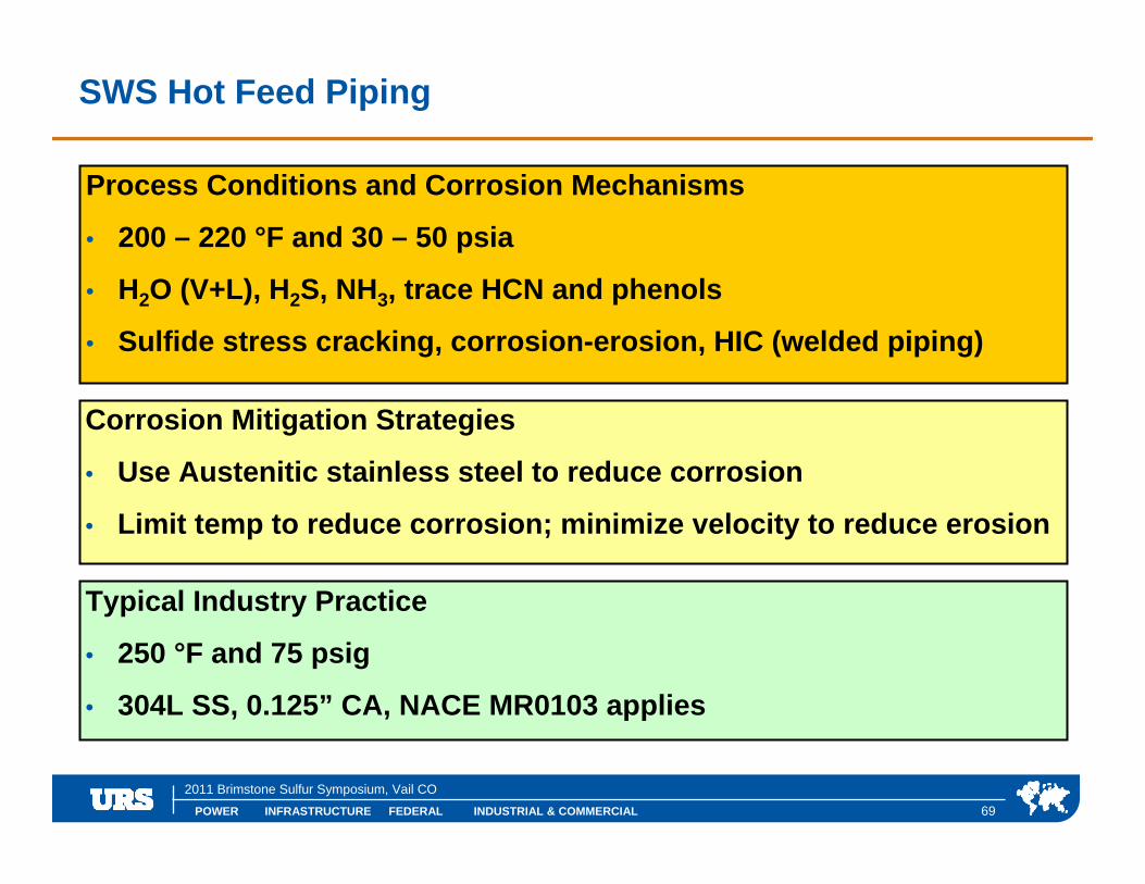
SWS Hot Feed Piping
Process Conditions and Corrosion Mechanisms
• 200 – 220 °F and 30 – 50 psia
• H2O (V+L), H2S, NH3, trace HCN and phenols
• Sulfide stress cracking, corrosion-erosion, HIC (welded piping)
Corrosion Mitigation Strategies
• Use Austenitic stainless steel to reduce corrosion
• Limit temp to reduce corrosion; minimize velocity to reduce erosion
Typical Industry Practice
• 250 °F and 75 psig
• 304L SS, 0.125” CA, NACE MR0103 applies
POWER INFRASTRUCTURE FEDERAL INDUSTRIAL & COMMERCIAL
2011 Brimstone Sulfur Symposium, Vail CO
70
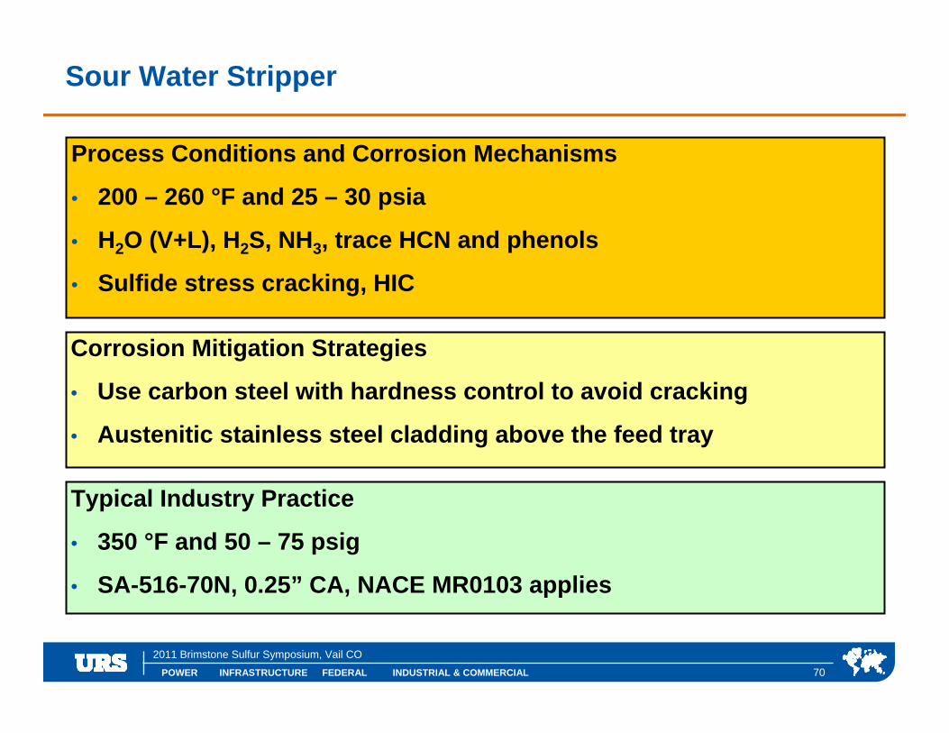
Sour Water Stripper
Process Conditions and Corrosion Mechanisms
• 200 – 260 °F and 25 – 30 psia
• H2O (V+L), H2S, NH3, trace HCN and phenols
• Sulfide stress cracking, HIC
Corrosion Mitigation Strategies
• Use carbon steel with hardness control to avoid cracking
• Austenitic stainless steel cladding above the feed tray
Typical Industry Practice
• 350 °F and 50 – 75 psig
• SA-516-70N, 0.25” CA, NACE MR0103 applies

POWER INFRASTRUCTURE FEDERAL INDUSTRIAL & COMMERCIAL
2011 Brimstone Sulfur Symposium, Vail CO
Discussion of SWS Condensing Systems
There are two types of SWS condensing systems:
1. External condenser with reflux drum and pumps;
2. Internal condensing section with an external pumparound cooler.
Some key points to remember:
• External condensing systems experience significantly greater corrosion
• Internal condensing systems are more expensive
• Operating problems with internal condensing systems are usually due to either (a) insufficient condensing height or (b) inadequate control of tower overhead temperature

POWER INFRASTRUCTURE FEDERAL INDUSTRIAL & COMMERCIAL
2011 Brimstone Sulfur Symposium, Vail CO
72
Sour Water Stripper Condensing Section (Internal)
Process Conditions and Corrosion Mechanisms
• 180 – 200 °F and 25 - 30 psia
• H2O (V+L), H2S, NH3, HCN and phenols may concentrate
• Ammonium bicarbonate corrosion, sulfide stress cracking, HIC
Corrosion Mitigation Strategies
• Use Austenitic stainless cladding to reduce corrosion
• High liquid rates minimize dry areas for condensation to occur
Typical Industry Practice
• 350 °F and 50 – 75 psig
• SA-516-70N + 0.125” SS clad, NACE MR0103 applies

POWER INFRASTRUCTURE FEDERAL INDUSTRIAL & COMMERCIAL
2011 Brimstone Sulfur Symposium, Vail CO
73
SWS Pumparound Cooler
Process Conditions and Corrosion Mechanisms
• 140 – 180 °F and 20 – 30 psia
• H2O (L), H2S, NH3,
• Ammonium bicarbonate corrosion, sulfide stress cracking, HIC
Corrosion Mitigation Strategies
• Austenitic stainless steel to minimize corrosion
• Low temperature reduces corrosion but increases cracking concern
Typical Industry Practice
• 250 °F and 50 – 75 psig
• 304L SS, 0.0675” CA, NACE MR0103 applies

POWER INFRASTRUCTURE FEDERAL INDUSTRIAL & COMMERCIAL
2011 Brimstone Sulfur Symposium, Vail CO
74
SWS Condenser (External, Process Side)
Process Conditions and Corrosion Mechanisms
• 180 – 240 °F and 20 – 30 psia
• H2O (V+L), H2S, NH3, HCN and phenols may concentrate
• Ammonium bicarbonate corrosion, sulfide stress cracking, HIC
Corrosion Mitigation Strategies
• Corrosion resistant alloys required
Typical Industry Practice
• 300 °F and 50 – 75 psia
• Titanium tubes, 316L SS, 0.125” CA, NACE MR0103 applies

POWER INFRASTRUCTURE FEDERAL INDUSTRIAL & COMMERCIAL
2011 Brimstone Sulfur Symposium, Vail CO
75
SWS Overhead Piping
Process Conditions and Corrosion Mechanisms
• 180 – 190 °F and 25 – 30 psia
• H2O (V), H2S, NH3, trace HCN and phenols
• Ammonium bicarbonate corrosion, sulfide stress cracking
Corrosion Mitigation Strategies
• Use carbon steel with hardness control to limit cracking
• Prevent condensation with effective heat trace to 190 °F
Typical Industry Practice
• 250 °F and 50 – 75 psig
• A-106B, 0.25” CA, NACE MR0103 applies

POWER INFRASTRUCTURE FEDERAL INDUSTRIAL & COMMERCIAL
2011 Brimstone Sulfur Symposium, Vail CO
References
1. “Petroleum and Natural Gas Industries – Materials for use in H2S-Containing environments in oil and gas production”, ANSI/NACE MR0175 / ISO 15156-1, October 2009.
2. “Materials Resistant to Sulfide Stress Cracking in Corrosive Petroleum Refining Environments”, NACE MR0103, October, 2010.
3. “Methods and Controls to Prevent In-Service Cracking of Carbon Steel Weldments in Corrosive Petroleum Refining Envrionments”, NACE SP0472-2010 (formerly RP0472), 2010.
4. Martens, et. al., “Sulfur Recovery Units Corrosion Overview”, NACE Fall Committee Week, September 1998.
5. “Survey of Construction Materials and Corrosion in Sour Water Strippers – 1978”, API Publication 950, April 1983.


