POWER SAVER / TIMER - Velleman · 3 Assembly hints The power saver turns off your equipment after a...
16
POWER SAVER / TIMER K8075 H8075IP-1 Turns off y our e quipment aft er a pres et t i me, it hel ps y ou s av e money an d i t i nc reas es s a fet y
Transcript of POWER SAVER / TIMER - Velleman · 3 Assembly hints The power saver turns off your equipment after a...

POWER SAVER / TIMER
K8075
H8075IP-1
Turns off your equipment after a preset time, it
helps you save money and it increases safety

VELLEMAN NV Legen Heirweg 33
9890 Gavere Belgium Europe
www.velleman.be www.velleman-kit.com

3
Assembly hints
The power saver turns off your equipment after a preset time. It helps you save money and it increases safety. FEATURES: Single button operation with LED mode indicator
continuous : 24h turn-off timer slow flashing : 4h or 8h turn-off timer fast flashing : 1h or 2h turn-off timer dim : idle
Choose short or long-running timers (one-time jumper setting) 10A suppressed relay output Easy to add to existing equipment
Applications: automatically turn off heating, cooling, lighting, entertainment systems, fans, pumps, sprin-klers, etc...
SPECIFICATIONS: Available timers: 1h / 2h / 4h / 8h / 24h Relay output: 10A / 240VAC max Power supply: 100 - 240VAC Dimensions: 65 x 50 x 26mm

4
Assembly hints
1. Assembly (Skipping this can lead to troubles ! ) Ok, so we have your attention. These hints will help you to make this project successful. Read them carefully. 1.1 Make sure you have the right tools: A good quality soldering iron (25-40W) with a small tip.
Wipe it often on a wet sponge or cloth, to keep it clean; then apply solder to the tip, to give it a wet look. This is called ‘thinning’ and will protect the tip, and enables you to make good connections. When solder rolls off the tip, it needs cleaning.
Thin raisin-core solder. Do not use any flux or grease.
A diagonal cutter to trim excess wires. To avoid injury when cutting excess leads, hold the lead so they cannot fly towards the eyes.
Needle nose pliers, for bending leads, or to hold components in place.
Small blade and Phillips screwdrivers. A basic range is fine.
For some projects, a basic multi-meter is required, or might be handy
1.2 Assembly Hints :
Make sure the skill level matches your experience, to avoid disappointments. Follow the instructions carefully. Read and understand the entire step before you perform each operation. Perform the assembly in the correct order as stated in this manual Position all parts on the PCB (Printed Circuit Board) as shown on the drawings. Values on the circuit diagram are subject to changes. Values in this assembly guide are correct* Use the check-boxes to mark your progress. Please read the included information on safety and customer service
* Typographical inaccuracies excluded. Always look for possible last minute manual updates, indicated as ‘NOTE’ on a separate leaflet.
0.000
5
Assembly hints
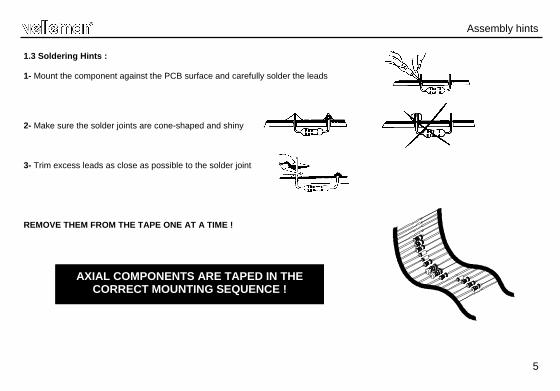
1.3 Soldering Hints :
1- Mount the component against the PCB surface and carefully solder the leads
2- Make sure the solder joints are cone-shaped and shiny
3- Trim excess leads as close as possible to the solder joint
REMOVE THEM FROM THE TAPE ONE AT A TIME !
AXIAL COMPONENTS ARE TAPED IN THE CORRECT MOUNTING SEQUENCE !

6
ZD...CATHODE
D...CATHODE
R1 : 330K (3 - 3 - 4 - B - 9) R2 : 330K (3 - 3 - 4 - B - 9) R3 : 220 (2 - 2 - 1 - B - 9)
R4 : 47K (7 - 7 - 3 - B) R5 : 1K (1 - 0 - 2 - B) R6 : 1K (1 - 0 - 2 - B) R7 : 10K (1 - 0 - 3 - B) R8 : 10K (1 - 0 - 3 - B) R9 : 10K (1 - 0 - 3 - B) R10 : 2K2 (2 - 2 - 2 - B) R11 : 6K8 (6 - 8 - 2 - B) R12 : 3K9 (3 - 9 - 2 - B)
5. Resistors
IC1 : 8p
6. IC socket. Watch the position of the notch!
Construction
D1 : 1N4148
1. Diodes. Watch the polarity ! 4. Metal film resistors (1%)
R...
ZD1 : 5V1/0.5W ZD2 : 24V/1.3W
2. Zenerdiodes. Watch the polarity !
D2 : 1N4007 D3 : 1N4007 D4 : 1N4007 D5 : 1N4007
3. Diodes. Watch the polarity !
D...CATHODE
R...
C1 : 100nF (104) C2 : 100nF (104)
7. Capacitors. c...

7
Construction
SK6 : 4p
9. Board to wire connector
JP1 : 2p
10. Pin header
Choose timer :
Mounted : 2h / 8h Not mounted : 1h / 4h
11. Shunt
VDR1 : VDR300
13. VDR
L N
L N
12. PCB terminals
T1 : BC547B T2 : BC547B
8. Transistors
AC power out
AC power in
C3 : 100µF / 35V C4 : 100µF / 35V
14. Electrolytic capacitors Watch the polarity!
C...

8
Construction
Choose operation voltage :
230V :
C5 : 0,47µF / 630V 115V :
C5 : 0,68µF / 400V
15. Capacitor
RY1 : VR10V241C (24DC - 10A - 1contact)
16. Relays
IC1 : VK8075
(programmed PIC10F200-I/PG)
17. IC. Watch the position of the notch!
CHECK THOROUGHLY ALL THE COMPONENTS FOR MISS MOUNTING, INCLUDING SOLDERING ERRORS.
PUT AN EXTRA THICK LAYER OF SOLDER ON THESE PCB TRACKS TO IMPROVE THEIR
CURRENT HANDLING CAPACITIES.
Fig. 1.0

9
Cut off a piece of shrinkable tube with a lenght equal to 2,5cm.
Slide the shrinkable tube over the wires of the female 'board to wire'-connector (fig. 2.0)
Solder the 4-pole female 'board to wire' connector to the push button using the figure below to check the accuracy of the connections (see figure 3.0)
Attention: Always make sure to slide down the shrinking tube far enough from the soldering points!
Slide the shrinkable tube over the soldered joints and heat them using a hair dryer or, better still, using a paint stripper.
18. Wiring the push button
(Orange)
(Red)
1
(Yellow)
2
3 4
(Brown) Leend : LED - LED +
Push button
1
2
3
4
Wiring the push button
Fig. 2.0
4 (Yellow)
3 (Orange)
1 (Brown)
2 (Red)
Fig. 3.0

10
Wiring the push button
In case you want to use a different push button, make sure it is rated for the AC-voltage. If you do not use the included push button, you can mount a 3mm LED on the PCB.
COLOR= 2...5
LD...
CATHODE
Watch the polarity !
Do not use both simultaneously (LED & included push button)

11
19. Final connection & use
Final connection & use
CAUTION: All PARTS OF THE CIRCUIT CARRY DANGEROUS VOLTAGES (MAINS) ! OBSERVE ALL SAFETY REQUIREMENTS THAT MIGHT APPLY !
MOUNT THIS KIT PREFERABLY IN AN ISOLATED ENCLOSURE
Connect your application (ex. lamp) to the unit (Lout & N) Connect the power supply to the power connections of the PCB (L
&N), see fig. 4.0. Warning: It is important to position jumper JP1in the
correct mode prior to connecting the kit to the AC power
L
N
Application
Push button AC POWER
Fig. 4.0
12
Use
Never modify the JP1 mode setting while the unit is still live! Jumper selection: First, choose the desired timer function, i.e. a long-term or a short-term timer.
(1) Long-term timer.
Mount the jumper (JP1) At power-on, the pushbutton LED (or LD1) will flash slowly twice, hereby indicating that long-term
timers have been selected (2h or 8h turn-off timer).
(2) Short-term timer.
Remove the jumper (JP1) At power-on, the pushbutton LED (or LD1) will flash fast twice, hereby indicating that short-term timers
have been selected (1h or 4h turn-off timer).
13
Use : Push button briefly: turn-on relay and toggle between a short or a long turn-off delay.
Short turn-off delay (1h or 4h, depending on setting of jumper JP1) Pushbutton LED (or LD1) blinks fast.
Long turn-off delay (2h or 8h, depending on setting of jumper JP2)
Pushbutton LED (or LD1) blinks slowly. Hold button for 2-3s: turn-on relay and activate 24h turn-off timer. Pushbutton LED (or LD1) is steady lit
Hold button again for 2-3s: turn-off relay Pushbutton LED (or LD1) is dimly lit

14
20. Schematic diagram
Diagram

15
21. PCB
PCB

5 4 1 0 3 2 9 3 4 8 3 3 5Modifications and typographical errors reserved © Velleman nv. H8075IP’1 (rev1) - 2014
VELLEMAN NV Legen Heirweg 33, B-9890 GAVERE
Belgium (Europe)