Power over Ethernet Power View Pro 3 - Microsemi · 8 Troubleshooting ... PowerDsine’s Power over...
77
Power over Ethernet Power View Pro 3 User Guide Revision 1.7 Catalog Number 06-0051-056 © 2009 Microsemi Corp. All rights reserved. This document is subject to change without notice.
Transcript of Power over Ethernet Power View Pro 3 - Microsemi · 8 Troubleshooting ... PowerDsine’s Power over...

Power over Ethernet
Power View Pro 3 User Guide
Revision 1.7
Catalog Number 06-0051-056
© 2009 Microsemi Corp. All rights reserved.
This document is subject to change without notice.

Power over Ethernet Power View Pro 3 User Guide
Copyright 2009 Microsemi Rev. 1.7, 203-Oct-09 Analog Mixed Signal Group
2381 Morse Avenue, Irvine, CA 92614, USA; Phone (USA): (800) 713-4113, (ROW): (949) 221-7100 Fax: (949) 756-0308
2
Acknowledgements
All other products or trademarks are property of their respective owners.
The product described by this manual is a licensed product of Microsemi.
Abbreviations and Terminology
Abbreviations are spelled out in full when first used or are listed in Table 1-1. Only industry-standard terms are used throughout this manual.
Note: Covered under U.S patent S/N 6,473,608. Other patents are pending.
Power over Ethernet Power View Pro 3 User Guide
Copyright 2009 Microsemi Rev. 1.7, 203-Oct-09 Analog Mixed Signal Group
2381 Morse Avenue, Irvine, CA 92614, USA; Phone (USA): (800) 713-4113, (ROW): (949) 221-7100 Fax: (949) 756-0308
3
Table of Contents 1 About this Guide........................................................................................................................................ 6
1.1 Objectives .............................................................................................................................................. 6
1.2 Audience................................................................................................................................................ 6
1.3 Organization .......................................................................................................................................... 6
1.4 Conventions........................................................................................................................................... 7
1.5 Related Documentation ......................................................................................................................... 7
1.6 Abbreviations ......................................................................................................................................... 7
2 Introducing the Power View Pro................................................................................................................ 8
2.1 Features................................................................................................................................................. 8
2.2 System Capabilities ............................................................................................................................... 8
2.3 Configuration Options ............................................................................................................................ 9
2.4 Security and User Authentication ........................................................................................................ 10
2.4.1 Web Security ............................................................................................................................... 10
2.4.2 SNMP Security ............................................................................................................................ 10
2.4.3 Telnet/SSH Security .................................................................................................................... 10
3 Installation ............................................................................................................................................... 11
3.1 System Requirements ......................................................................................................................... 11
3.2 Hardware Setup................................................................................................................................... 11
3.3 Configuration Procedure...................................................................................................................... 12
3.3.1 Connecting to the Unit Using a Web Browser............................................................................. 12
3.3.2 Connecting to the Unit Using Window's Telnet ........................................................................... 12
3.3.3 Connecting to Unit Using a DB9 RS232 and a Hyper Terminal Application ............................... 12
3.3.4 Connecting via USB RS232 Serial Communication Virtual Port ................................................. 14
3.3.5 Configuring the System via the HyperTerminal........................................................................... 14
3.4 Configuring the TFTP Server............................................................................................................... 17
4 Web Interface Description....................................................................................................................... 18
4.1 Overview.............................................................................................................................................. 18
4.2 Opening Screen................................................................................................................................... 18
4.3 View Menu ........................................................................................................................................... 18
4.3.1 View Status Screen (65xx, 65xxG, 80xx Midspan Series).......................................................... 19
4.3.2 View - Status Screen (70xxG Mid Power Midspan Series) ......................................................... 20
4.3.3 View - Status Screen (90xxG High Power Midspan Series) ....................................................... 20
4.3.4 View - Status Screen Elements................................................................................................... 21
4.3.5 View - Configuration Summary.................................................................................................... 26
4.3.6 View - Product Information .......................................................................................................... 31
4.3.7 System Configuration Screen...................................................................................................... 31
4.3.8 System Configuration SNMP....................................................................................................... 41
4.3.9 System Configuration SNMPv3................................................................................................... 44
4.3.10 System Configuration Security .................................................................................................... 45
4.3.11 System Configuration - RADIUS ................................................................................................. 48
4.3.12 System Configuration - Dynamic UPS Power Management....................................................... 49
4.3.13 System Configuration Product Parameters - 65xx, 65xxG, 70xxG, 80xx Family........................ 52
4.3.14 System Configuration Product Parameters - 90xxG Family........................................................ 53
4.3.15 System Configuration Maintenance ............................................................................................ 54
4.4 Port Configuration Screen ................................................................................................................... 55
4.4.1 Port Configuration Enable/Disable .............................................................................................. 55
4.4.2 Port Configuration Detailed ......................................................................................................... 56
4.4.3 Port Configuration - Weekly Schedule ........................................................................................ 58
5 Midspan 90xxG - Power Backup and Power Management .................................................................... 60
5.1 Viewing the Power Source Status ....................................................................................................... 61
5.2 RPS Power Backup ............................................................................................................................. 61
5.3 Dual 90xxG Midspan Power Backup................................................................................................... 62
5.3.1 Midspan 90xxG to Midspan 90xxG Power Shift.......................................................................... 63
5.3.2 Changing Power Limit (%) by SNMP .......................................................................................... 63
5.3.3 Activating Dynamic UPS Power Management ............................................................................ 64
5.3.4 Power Failure and Invalid Midspan to Midspan Power Backup Connection Report................... 65
6 SNMP Monitoring and Configuration....................................................................................................... 66
Power over Ethernet Power View Pro 3 User Guide
Copyright 2009 Microsemi Rev. 1.7, 203-Oct-09 Analog Mixed Signal Group
2381 Morse Avenue, Irvine, CA 92614, USA; Phone (USA): (800) 713-4113, (ROW): (949) 221-7100 Fax: (949) 756-0308
4
6.1 Enabling Midspan SNMP..................................................................................................................... 66
6.2 SNMP MIBs ......................................................................................................................................... 66
6.3 RFC3621 PoE MIB .............................................................................................................................. 67
6.4 Private MIB .......................................................................................................................................... 67
7 Software Upgrade ................................................................................................................................... 70
7.1 Architecture.......................................................................................................................................... 70
7.2 Software Upgrade from Version 2.xx to 3.xx, or from 3.xx to 3.xy ...................................................... 70
7.2.1 General ........................................................................................................................................ 70
7.2.2 Upgrade Process......................................................................................................................... 71
8 Troubleshooting....................................................................................................................................... 73
List of Figures Figure 2-1: Management Deployment...........................................................................................................................9
Figure 3-1: Connecting the PoE Unit.......................................................................................................................... 11
Figure 3-2: Windows XP Hyper Terminal Specifications ......................................................................................... 13
Figure 3-3: Putty Configuration Window .................................................................................................................... 13
Figure 3-4: PuTTY Serial Configuration Window Specifications ............................................................................ 14
Figure 3-5: Main Menu Screen .................................................................................................................................... 15
Figure 3-6: View Menu Screen .................................................................................................................................... 15
Figure 3-7: Configuration & Maintenance Menu ....................................................................................................... 16
Figure 3-8: NBTFTP Server Window.......................................................................................................................... 17
Figure 4-1: Power View Pro Main Window ................................................................................................................ 18
Figure 4-2: View Menu.................................................................................................................................................. 19
Figure 4-3: View - Status Screen (65xx, 65xxG, 80xx Midspan Series) ............................................................... 19
Figure 4-4: View - Status Screen (70xxG Mid Power Midspan Series)................................................................. 20
Figure 4-5: View - Status Screen (90xxG High Power Midspan Series) ............................................................... 21
Figure 4-6: Ports Status Panel .................................................................................................................................... 21
Figure 4-7: Detailed Port Description Information .................................................................................................... 24
Figure 4-8: Manual Override Deactivation key.......................................................................................................... 25
Figure 4-9: Weekly Activated/Deactivated Ports ...................................................................................................... 26
Figure 4-10: View - Configuration Summary Screen................................................................................................ 27
Figure 4-11: IP in-Use Window ................................................................................................................................... 27
Figure 4-12: Static Network Configuration Window.................................................................................................. 28
Figure 4-13: Remote Servers Window ....................................................................................................................... 28
Figure 4-14: Date and Time Window.......................................................................................................................... 28
Figure 4-15: Remote Trap SNMP Managers List ..................................................................................................... 29
Figure 4-16: Remote Access & Security Window ..................................................................................................... 29
Figure 4-17: Advanced Features Window ................................................................................................................. 30
Figure 4-18: View - Product Information Screen....................................................................................................... 31
Figure 4-19: System Configuration Screen ............................................................................................................... 32
Figure 4-20: System Configuration Network Screen................................................................................................ 32
Figure 4-21: Auto Services Configuration by DHCP ................................................................................................ 33
Figure 4-22: Defining Vendor Class............................................................................................................................ 34
Figure 4-23: Set Vendor Class String......................................................................................................................... 34
Figure 4-24: Set Predefined Options .......................................................................................................................... 35
Figure 4-25: Adding Predefined Sub Types .............................................................................................................. 35
Figure 4-26: SNMP Manager Option Type ................................................................................................................ 36
Figure 4-27: Midspan Option Code............................................................................................................................. 36
Figure 4-28: SysLog Option Type ............................................................................................................................... 36
Figure 4-29: RADIUS Option Type ............................................................................................................................. 37
Figure 4-30: Scope Options Configurations .............................................................................................................. 37
Figure 4-31: Midspan Scope Options ......................................................................................................................... 38
Figure 4-32: Configuring Scope Options.................................................................................................................... 38
Figure 4-33: Advertised Scope Options ..................................................................................................................... 39
Figure 4-34: SNMP Scope Options ............................................................................................................................ 39
Figure 4-35: Setting SNMP Manager IP List ............................................................................................................. 39
Figure 4-36: Midspan Automatic Service Configuration .......................................................................................... 40
Figure 4-37: Syslog Server Log Events ..................................................................................................................... 40
Figure 4-38: System Configuration SNMP Screen ................................................................................................... 42
Power over Ethernet Power View Pro 3 User Guide
Copyright 2009 Microsemi Rev. 1.7, 203-Oct-09 Analog Mixed Signal Group
2381 Morse Avenue, Irvine, CA 92614, USA; Phone (USA): (800) 713-4113, (ROW): (949) 221-7100 Fax: (949) 756-0308
5
Figure 4-39: SNMPv2 Window .................................................................................................................................... 42
Figure 4-40: Remote Trap SNMP Managers List ..................................................................................................... 44
Figure 4-41: System Configuration SNMPv3 Screen............................................................................................... 44
Figure 4-42: System Configuration Security Screen ................................................................................................ 46
Figure 4-43: Web Secure Access & Configuration Window.................................................................................... 46
Figure 4-44: Telnet/SSH View & Configuration Window ......................................................................................... 47
Figure 4-45: Remote Access Window ........................................................................................................................ 47
Figure 4-46: RADIUS Configuration Screen.............................................................................................................. 48
Figure 4-47: Dynamic UPS Power Management...................................................................................................... 49
Figure 4-48: Dynamic UPS Power Management Screen ........................................................................................ 50
Figure 4-49: Midspan Enforced Maximum Power Levels ........................................................................................ 51
Figure 4-50: UPS-Midspan Communication Failure................................................................................................. 51
Figure 4-51: System Configuration Product Parameters Screen ........................................................................... 52
Figure 4-52: System Configuration Product Parameters Screen ........................................................................... 53
Figure 4-53: System Configuration Maintenance Screen........................................................................................ 54
Figure 4-54: Port Configuration Screen ..................................................................................................................... 55
Figure 4-55: Port Configuration Enable/Disable Screen.......................................................................................... 56
Figure 4-56: Port Configuration Detailed Screen (65xx,65xxG, 70xxG, 90xxG Family) ..................................... 57
Figure 4-57: Port Configuration Detailed Screen (80xx Midspan Family)............................................................. 57
Figure 4-58: Port Configuration – Weekly Schedule ................................................................................................ 59
Figure 5-1: External Power Backup ............................................................................................................................ 60
Figure 5-2: Secondary Midspan Power Backup ....................................................................................................... 60
Figure 5-3: Power Source Status ................................................................................................................................ 61
Figure 5-4: Power Backup Mode................................................................................................................................. 62
Figure 5-5: View - Status Window (Power Shift Display) ........................................................................................ 63
Figure 5-6: Midspan Power Limit by SNMP............................................................................................................... 64
Figure 6-1: Network Management Tool...................................................................................................................... 66
Figure 6-2: MIB Tree Structure.................................................................................................................................... 67
Figure 6-3: MIBs Management Functionalities ......................................................................................................... 68
Figure 7-1: System Software Architecture ................................................................................................................. 70
List of Tables Table 1-1: List of Abbreviations ......................................................................................................................................7
Table 4-1: Main Status Indications.............................................................................................................................. 22
Table 4-2: 65xx, 65xxG, 70xxG and 90xxG Gigabit High Power Midspan Port Status Indications .................. 22
Table 4-3: 80xx High Power (Four Pair) Midspan Port Status Indications............................................................ 23
Table 4-4: Midspan Status Table Details ................................................................................................................... 24
Table 4-5: Detailed Port Description Information...................................................................................................... 24
Table 4-6: IP in User Parameters................................................................................................................................ 27
Table 4-7: System Configuration Network Screen Details ...................................................................................... 32
Table 4-8: SNMPv2 Field Details ................................................................................................................................ 43
Table 4-9: System Information Window ..................................................................................................................... 43
Table 4-10: RFC3621 PoE MIB Parameters ............................................................................................................. 43
Table 5-1: Power Backup Connectivity Options ....................................................................................................... 60
Table 5-2: SNMP Object IDs Affected by 90xxG Midspan Power Backup Mode Connection ........................... 61
Table 5-3: mainPowerUsageBudget SNMP OiD Vs Midspan Maximum Power.................................................. 64
Table 8-1: Troubeshooting Guide ............................................................................................................................... 73
Power over Ethernet Power View Pro 3 User Guide
Copyright 2009 Microsemi Rev. 1.7, 203-Oct-09 Analog Mixed Signal Group
2381 Morse Avenue, Irvine, CA 92614, USA; Phone (USA): (800) 713-4113, (ROW): (949) 221-7100 Fax: (949) 756-0308
6
1 About this Guide The following sections define the manual objectives, concepts used, conventions used and associated documentation
1.1 Objectives
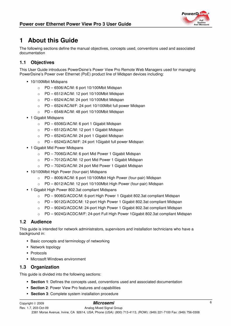
This User Guide introduces PowerDsine’s Power View Pro Remote Web Managers used for managing PowerDsine’s Power over Ethernet (PoE) product line of Midspan devices including:
� 10/100Mbit Midspans
o PD – 6506/AC/M: 6 port 10/100Mbit Midspan
o PD – 6512/AC/M: 12 port 10/100Mbit Midspan
o PD – 6524/AC/M: 24 port 10/100Mbit Midspan
o PD – 6524/AC/M/F: 24 port 10/100Mbit full power Midspan
o PD – 6548/AC/M: 48 port 10/100Mbit Midspan
� 1 Gigabit Midspans
o PD – 6506G/AC/M: 6 port 1 Gigabit Midspan
o PD – 6512G/AC/M: 12 port 1 Gigabit Midspan
o PD – 6524G/AC/M: 24 port 1 Gigabit Midspan
o PD – 6524G/AC/M/F: 24 port 1Gigabit full power Midspan
� 1 Gigabit Mid Power Midspans
o PD – 7006G/AC/M: 6 port Mid Power 1 Gigabit Midspan
o PD – 7012G/AC/M: 12 port Mid Power 1 Gigabit Midspan
o PD – 7024G/AC/M: 24 port Mid Power 1 Gigabit Midspan
� 10/100Mbit High Power (four-pair) Midspans
o PD – 8006/AC/M: 6 port 10/100Mbit High Power (four-pair) Midspan
o PD – 8012/AC/M: 12 port 10/100Mbit High Power (four-pair) Midspan
� 1 Gigabit High Power 802.3at compliant Midspans
o PD – 9006G/ACDC/M: 6-port High Power 1 Gigabit 802.3at compliant Midspan
o PD – 9012G/ACDC/M: 12-port High Power 1 Gigabit 802.3at compliant Midspan
o PD – 9024G/ACDC/M: 24-port High Power 1 Gigabit 802.3at compliant Midspan
o PD – 9024G/ACDC/M/F: 24-port Full High Power 1Gigabit 802.3at compliant Midspan
1.2 Audience
This guide is intended for network administrators, supervisors and installation technicians who have a background in:
� Basic concepts and terminology of networking
� Network topology
� Protocols
� Microsoft Windows environment
1.3 Organization
This guide is divided into the following sections:
� Section 1: Defines the concepts used, conventions used and associated documentation
� Section 2: Power View Pro features and capabilities
� Section 3: Complete system installation procedure
Power over Ethernet Power View Pro 3 User Guide
Copyright 2009 Microsemi Rev. 1.7, 203-Oct-09 Analog Mixed Signal Group
2381 Morse Avenue, Irvine, CA 92614, USA; Phone (USA): (800) 713-4113, (ROW): (949) 221-7100 Fax: (949) 756-0308
7
� Section 4: PowerView Pro Web interface detailed description
� Section 5: Midspan 90xxG - Power Backup and Management
� Section 6: SNMP Monitoring and Configuration
� Section 7: Upgrading Midspan software
� Section 8: Troubleshooting
1.4 Conventions
The various conventions used in defining commands and examples are given in the following table.
CONVENTION DEFINITION bold Keywords and commands
italics Represents a Web interface item
screen Displayed Information
Courier text Information to be entered
Notes Helpful information
1.5 Related Documentation
For additional information, refer to the following documentation:
� Product user guide (included inside the CD)
� Technical Note 132: Using RFC3621 PoE MIB with PowerDsine Midspans (included inside the CD).
� Creating SSL Certificate for Midspan Secured Web Server User Guide (included inside the CD)
� RFC3621 SNMP MIB, and private MIB (included inside the CD)
� IEEE Standard 802.3af, DTE Power via MDI
1.6 Abbreviations
Table 1-1: List of Abbreviations
PoE Power over Ethernet
NTP Network Time Protocol
DES Data Encryption Standard
MD5 Message Digest algorithm 5
MDI Media Dependent Interface
MIB Management Information Base
PD Powered Device
SNMP Simple Network Management Protocol SSL Secure Sockets Layer
TFTP Trivial File Transfer Protocol
SysLog System Log
SSH Secure Shell
RADIUS Remote Authentication Dial In User Service RPS
(RedundanRedundant Power Source
Power over Ethernet Power View Pro 3 User Guide
Copyright 2009 Microsemi Rev. 1.7, 203-Oct-09 Analog Mixed Signal Group
2381 Morse Avenue, Irvine, CA 92614, USA; Phone (USA): (800) 713-4113, (ROW): (949) 221-7100 Fax: (949) 756-0308
8
2 Introducing the Power View Pro PowerDsine’s Power View Pro is a management system used to monitor and control PowerDsine’s Power over Ethernet (PoE) Midspans, via a remote network management station. The system provides direct on-line power supervision, configuration, monitoring and diagnostics of PowerDsine products via WEB / SNMPv2c / SNMPv3 / Telnet/SSH.
NOTE:
The principle of operation is similar for all Midspan models described in this manual.
2.1 Features
The manager provides a number of unique features along with multiple access options:
� Access Options:
o HTTP: Web based friendly configuration interface for managing remote Power over Ethernet device
o SSL: Secured WEB based configuration
o SNMPv2c/v1 and secured plus encrypted SNMPv3
o Telnet: Remote terminal over Ethernet Network
o SSH: Remote encrypted terminal over Ethernet Network
� RFC3621 Power over Ethernet (PoE) SNMP MIBs
� Private MIB extension for RFC3621 PoE MIB
� RADIUS: Authentication and accounting for WEB / Telnet ./ SSH remote WEB users
� SysLog Server: Log events sent to remote SysLog Server
� Automatic Service Configuration by DHCP: Enables DHCP Server to configure automatically Midspan SNMP Manager's IP address, SysLog Servers IP address, Radius Servers IP address
� Easy software update during run time without affecting active PoE ports
� Configuration and real time monitoring using graphical representations of remote device
� System status display
� Automatic activation / deactivation of PoE ports based on weekly schedule configuration
� Automatic deactivation of low priority ports when UPS battery is low
� Power backup by 2nd Midspan or external Power Source (90xxG series only)
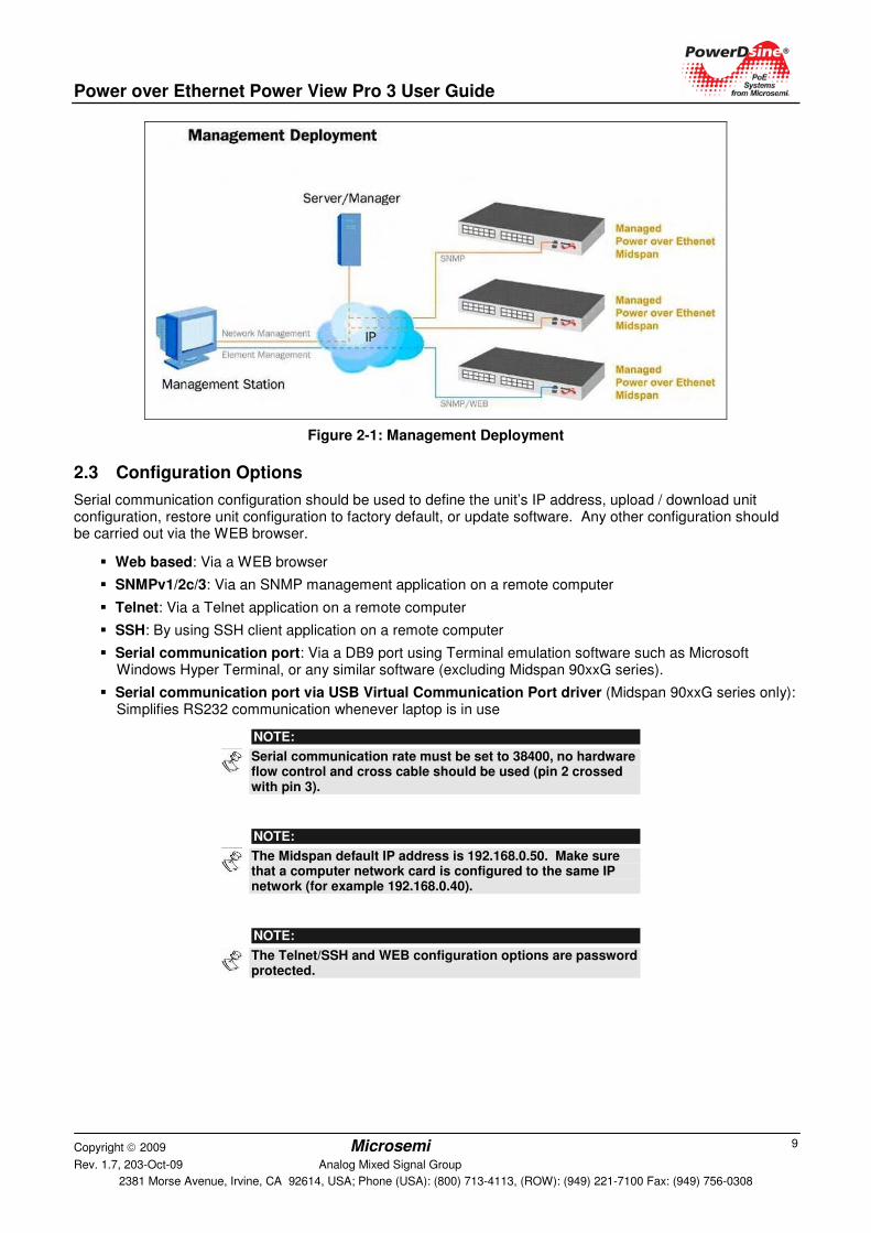
2.2 System Capabilities
The manager can be accessed from any computer using any WEB browser, SNMPv2c/SNMPv3 management station, Telnet/SSH, RS232 Terminal or USB virtual COM (Midspan 90xxG series). The Power View Pro enables monitoring and controlling of over Ethernet IP networks as shown in Figure 2-1.
Power over Ethernet Power View Pro 3 User Guide
Copyright 2009 Microsemi Rev. 1.7, 203-Oct-09 Analog Mixed Signal Group
2381 Morse Avenue, Irvine, CA 92614, USA; Phone (USA): (800) 713-4113, (ROW): (949) 221-7100 Fax: (949) 756-0308
9
Figure 2-1: Management Deployment
2.3 Configuration Options
Serial communication configuration should be used to define the unit’s IP address, upload / download unit configuration, restore unit configuration to factory default, or update software. Any other configuration should be carried out via the WEB browser.
� Web based: Via a WEB browser
� SNMPv1/2c/3: Via an SNMP management application on a remote computer
� Telnet: Via a Telnet application on a remote computer
� SSH: By using SSH client application on a remote computer
� Serial communication port: Via a DB9 port using Terminal emulation software such as Microsoft Windows Hyper Terminal, or any similar software (excluding Midspan 90xxG series).
� Serial communication port via USB Virtual Communication Port driver (Midspan 90xxG series only): Simplifies RS232 communication whenever laptop is in use
NOTE:
Serial communication rate must be set to 38400, no hardware flow control and cross cable should be used (pin 2 crossed with pin 3).
NOTE:
The Midspan default IP address is 192.168.0.50. Make sure that a computer network card is configured to the same IP network (for example 192.168.0.40).
NOTE:
The Telnet/SSH and WEB configuration options are password protected.
Power over Ethernet Power View Pro 3 User Guide
Copyright 2009 Microsemi Rev. 1.7, 203-Oct-09 Analog Mixed Signal Group
2381 Morse Avenue, Irvine, CA 92614, USA; Phone (USA): (800) 713-4113, (ROW): (949) 221-7100 Fax: (949) 756-0308
10
2.4 Security and User Authentication
Different security provisions are available, depending on the type of configuration used.
2.4.1 Web Security
Web interface has two user access levels, Viewer and Administrator.
� Viewer: The user has access only to Web pages which report Midspan status of configuration summary and can not change the Midspan configuration.
� Administrator: The user has full access to all Web pages and can edit the Midspan configuration.
NOTE:
SSL (https) offer encryption and authentication protection in addition to Viewer & Administrator access levels.
2.4.2 SNMP Security
o SNMP v1/v2: Community string is utilized for Get/Set/Trap authentication. SNMPv1/v2 is considered an unsecured protocol since the community string password can be easily intercepted by any Network sniffer device.
o SNMP v3: Overcome SNMPv1/v2 security issues by adding authenticating and encryption to SNMP packets.
2.4.3 Telnet/SSH Security
Since Telnet provides access to various configuration parameters, software update and data base upload/download, it is always password protected.
The Web interface has a dedicated password, while Telnet and SSH utilize the same passwords.
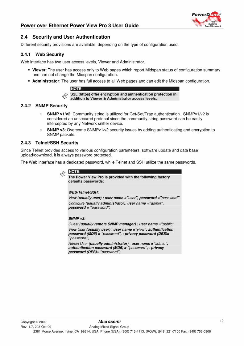
NOTE:
The PPoowweerr VViieeww PPrroo is provided with the following factory defaults passwords:
WEB/Telnet/SSH:
View (usually user) : user name =”user”, password =”password”
Configure (usually administrator): user name =”admin”, password = ”password”.
SNMP v3:
Guest (usually remote SNMP manager) : user name =”public”
View User (usually user) : user name =”view”, authentication password (MD5) = ”password”, : privacy password (DES)= ”password”,
Admin User (usually administrator) : user name =”admin”, authentication password (MD5) = ”password”, : privacy password (DES)= ”password”,
Power over Ethernet Power View Pro 3 User Guide
Copyright 2009 Microsemi Rev. 1.7, 203-Oct-09 Analog Mixed Signal Group
2381 Morse Avenue, Irvine, CA 92614, USA; Phone (USA): (800) 713-4113, (ROW): (949) 221-7100 Fax: (949) 756-0308
11
3 Installation The following sections detail the installation process.
3.1 System Requirements
The following hardware/software items are required to configure and operate the Power over Ethernet (PoE) Midspan:
� Computer with Ethernet Network card configured to the following parameters:
o IP: 192.168.0.40
o IP Mask: 255.255.255.0
� Ethernet cable.
� Ethernet switch connected to the computer and Midspan management RJ-45 port (user can use cross cable connected directly between the computer and the Midspan without needing to use an Ethernet Switch).
� Telnet application (already provided by Windows/Linux).
� A free serial communication port on the computer.
o Null-modem RS232 crossed cable(for PD-6548 use the provided cable)
o USB cable (90xxG Midspan series). For virtual com driver installation, refer to section 3.4.6.
Important: The Midspan is shipped with the default IP set to 192.168.0.50. Before connecting the Midspan to your network, verify that no other device has the same IP address.
3.2 Hardware Setup
Before configuring the units, set up your hardware as follows:
1. Connect an AC power cable to the PoE unit.
2. Verify that all LEDs are lit (self test).
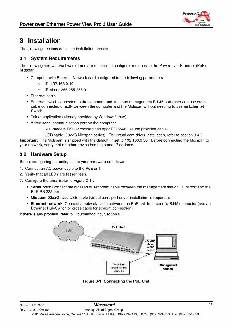
3. Configure the units (refer to Figure 3-1):
� Serial port: Connect the crossed null-modem cable between the management station COM port and the PoE RS 232 port.
� Midspan 90xxG: Use USB cable (virtual com. port driver installation is required).
� Ethernet network: Connect a network cable between the PoE unit front panel’s RJ45 connector (use an Ethernet Hub/Switch or cross cable for straight connection).
If there is any problem, refer to Troubleshooting, Section 8.
Figure 3-1: Connecting the PoE Unit
Power over Ethernet Power View Pro 3 User Guide
Copyright 2009 Microsemi Rev. 1.7, 203-Oct-09 Analog Mixed Signal Group
2381 Morse Avenue, Irvine, CA 92614, USA; Phone (USA): (800) 713-4113, (ROW): (949) 221-7100 Fax: (949) 756-0308
12
3.3 Configuration Procedure
The following sections describe how to install the unit via the configuration options.
The following connection options are available:
� Connecting to the Unit Using a Web Browser
� Connecting to the Unit Using Window's Telnet
� Connecting to Unit Using a DB9 RS232 and a Hyper Terminal Application (for PD-6548 use the special cable provided with the unit
� Connecting via USB RS232 Serial Communication Virtual Port, page 14 (90xxG Midspan series)
After connecting to the unit, the unit must be configured.
� Configuring the System via the HyperTerminal, page 14
Configure the TFTP server for optional software updates and to transfer unit configuration to and from the host.
� Configuring the TFTP Server, page 17
3.3.1 Connecting to the Unit Using a Web Browser
1. Open the web browser.
2. In the address field type:
192.168.0.50
3.3.2 Connecting to the Unit Using Window's Telnet
1. In the Start Menu, select Run.
2. Type:
cmd.
The DOS window appears.
3. Type:
telnet 192.168.0.50.
4. Type the username and password.
NOTE:
Use the web browser to view the System Configuration->Security web page and make sure that the Telnet is enabled.
3.3.3 Connecting to Unit Using a DB9 RS232 and a Hyper Terminal Application
When configuring the system via an RS232, the type of configuration performed depends on the operating system.
3.3.3.1 Windows 2000 and Windows XP
1. In the Start Menu, select:
Start >Programs >Accessories >Communications > HyperTerminal.
The Hyper Terminal window appears (Figure 3-2).
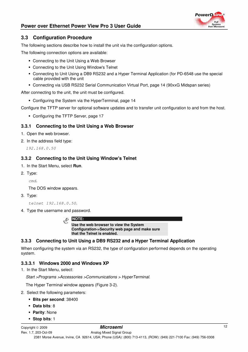
2. Select the following parameters:
� Bits per second: 38400
� Data bits: 8
� Parity: None
� Stop bits: 1
Power over Ethernet Power View Pro 3 User Guide
Copyright 2009 Microsemi Rev. 1.7, 203-Oct-09 Analog Mixed Signal Group
2381 Morse Avenue, Irvine, CA 92614, USA; Phone (USA): (800) 713-4113, (ROW): (949) 221-7100 Fax: (949) 756-0308
13
� Flow control: None
Figure 3-2: Windows XP Hyper Terminal Specifications
3.3.3.2 Windows Vista
The HyperTerminal serial communication was omitted from the Windows Vista. Use PuTTY, HyperTerminal freeware serial communication software or any other commercial serial communication software tool.
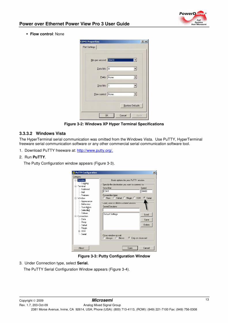
1. Download PuTTY freeware at: http://www.putty.org/.
2. Run PuTTY.
The Putty Configuration window appears (Figure 3-3).
Figure 3-3: Putty Configuration Window
3. Under Connection type, select Serial.
The PuTTY Serial Configuration Window appears (Figure 3-4).
Power over Ethernet Power View Pro 3 User Guide
Copyright 2009 Microsemi Rev. 1.7, 203-Oct-09 Analog Mixed Signal Group
2381 Morse Avenue, Irvine, CA 92614, USA; Phone (USA): (800) 713-4113, (ROW): (949) 221-7100 Fax: (949) 756-0308
14
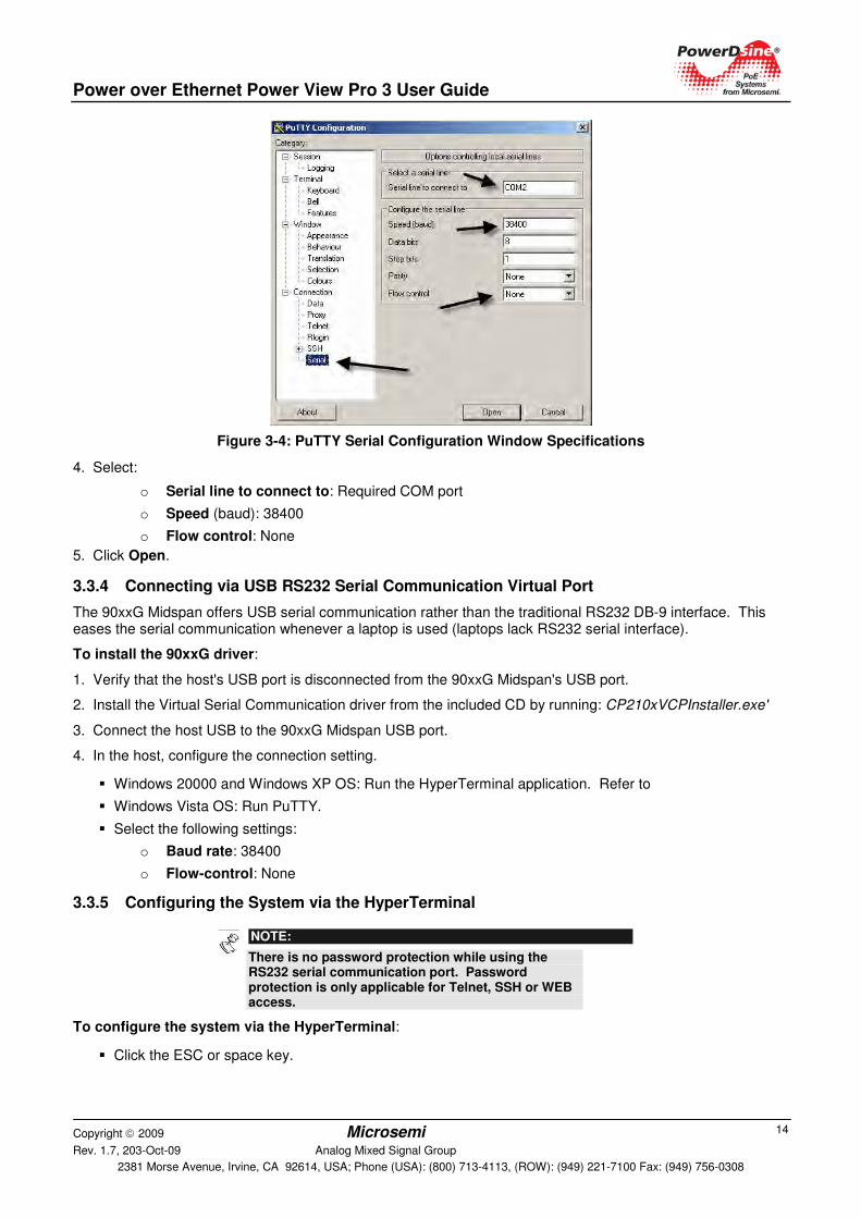
Figure 3-4: PuTTY Serial Configuration Window Specifications
4. Select:
o Serial line to connect to: Required COM port
o Speed (baud): 38400
o Flow control: None
5. Click Open.
3.3.4 Connecting via USB RS232 Serial Communication Virtual Port
The 90xxG Midspan offers USB serial communication rather than the traditional RS232 DB-9 interface. This eases the serial communication whenever a laptop is used (laptops lack RS232 serial interface).
To install the 90xxG driver:
1. Verify that the host's USB port is disconnected from the 90xxG Midspan's USB port.
2. Install the Virtual Serial Communication driver from the included CD by running: CP210xVCPInstaller.exe'
3. Connect the host USB to the 90xxG Midspan USB port.
4. In the host, configure the connection setting.
� Windows 20000 and Windows XP OS: Run the HyperTerminal application. Refer to
� Windows Vista OS: Run PuTTY.
� Select the following settings:
o Baud rate: 38400
o Flow-control: None
3.3.5 Configuring the System via the HyperTerminal
NOTE:
There is no password protection while using the RS232 serial communication port. Password protection is only applicable for Telnet, SSH or WEB access.
To configure the system via the HyperTerminal:
� Click the ESC or space key.
Power over Ethernet Power View Pro 3 User Guide
Copyright 2009 Microsemi Rev. 1.7, 203-Oct-09 Analog Mixed Signal Group
2381 Morse Avenue, Irvine, CA 92614, USA; Phone (USA): (800) 713-4113, (ROW): (949) 221-7100 Fax: (949) 756-0308
15
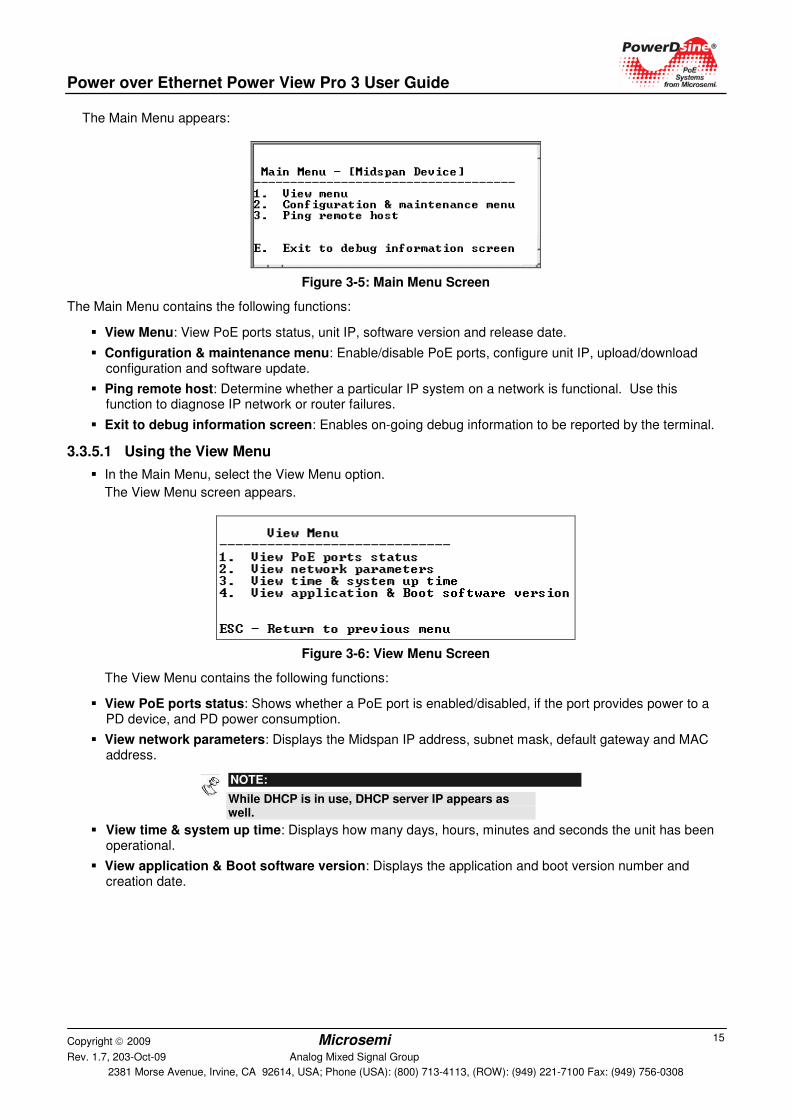
The Main Menu appears:
Figure 3-5: Main Menu Screen
The Main Menu contains the following functions:
� View Menu: View PoE ports status, unit IP, software version and release date.
� Configuration & maintenance menu: Enable/disable PoE ports, configure unit IP, upload/download configuration and software update.
� Ping remote host: Determine whether a particular IP system on a network is functional. Use this function to diagnose IP network or router failures.
� Exit to debug information screen: Enables on-going debug information to be reported by the terminal.
3.3.5.1 Using the View Menu
� In the Main Menu, select the View Menu option.
The View Menu screen appears.
Figure 3-6: View Menu Screen
The View Menu contains the following functions:
� View PoE ports status: Shows whether a PoE port is enabled/disabled, if the port provides power to a PD device, and PD power consumption.
� View network parameters: Displays the Midspan IP address, subnet mask, default gateway and MAC address.
NOTE:
While DHCP is in use, DHCP server IP appears as well.
� View time & system up time: Displays how many days, hours, minutes and seconds the unit has been operational.
� View application & Boot software version: Displays the application and boot version number and creation date.
Power over Ethernet Power View Pro 3 User Guide
Copyright 2009 Microsemi Rev. 1.7, 203-Oct-09 Analog Mixed Signal Group
2381 Morse Avenue, Irvine, CA 92614, USA; Phone (USA): (800) 713-4113, (ROW): (949) 221-7100 Fax: (949) 756-0308
16
3.3.5.2 Using the Configuration & Maintenance Menu
� In the Main Menu, select the Configuration & Maintenance Menu.
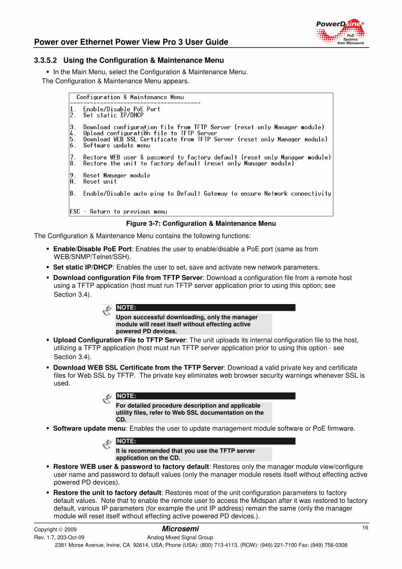
The Configuration & Maintenance Menu appears.
Figure 3-7: Configuration & Maintenance Menu
The Configuration & Maintenance Menu contains the following functions:
� Enable/Disable PoE Port: Enables the user to enable/disable a PoE port (same as from WEB/SNMP/Telnet/SSH).
� Set static IP/DHCP: Enables the user to set, save and activate new network parameters.
� Download configuration File from TFTP Server: Download a configuration file from a remote host using a TFTP application (host must run TFTP server application prior to using this option; see
Section 3.4).
NOTE:
Upon successful downloading, only the manager module will reset itself without effecting active powered PD devices.
� Upload Configuration File to TFTP Server: The unit uploads its internal configuration file to the host, utilizing a TFTP application (host must run TFTP server application prior to using this option - see
Section 3.4).
� Download WEB SSL Certificate from the TFTP Server: Download a valid private key and certificate files for Web SSL by TFTP. The private key eliminates web browser security warnings whenever SSL is used.
NOTE:
For detailed procedure description and applicable utility files, refer to Web SSL documentation on the CD.
� Software update menu: Enables the user to update management module software or PoE firmware.
NOTE:
It is recommended that you use the TFTP server application on the CD.
� Restore WEB user & password to factory default: Restores only the manager module view/configure user name and password to default values (only the manager module resets itself without effecting active powered PD devices).
� Restore the unit to factory default: Restores most of the unit configuration parameters to factory default values. Note that to enable the remote user to access the Midspan after it was restored to factory default, various IP parameters (for example the unit IP address) remain the same (only the manager module will reset itself without effecting active powered PD devices.).
Power over Ethernet Power View Pro 3 User Guide
Copyright 2009 Microsemi Rev. 1.7, 203-Oct-09 Analog Mixed Signal Group
2381 Morse Avenue, Irvine, CA 92614, USA; Phone (USA): (800) 713-4113, (ROW): (949) 221-7100 Fax: (949) 756-0308
17
� Reset Manager Module: Manager module resets itself only, without effecting active powered PD devices.
� Reset unit: Reset the entire unit, which causes all powered PD devices to be turned off for several seconds, and then re-powered.
� Enable/Disable auto ping to Default Gateway to ensure Network connectivity: Ping default gateway every five seconds. After 10 consecutive ping failures, Network Management Module will reset itself without effecting PoE ports.
� ESC: Return to Previous Menu
3.3.5.3 Using the Ping Remote Host Menu
The Ping Remote Host Menu is utilized to test the TCP/IP configuration by using the ping command. Ping is useful for verifying proper network configuration or a routing failure.
To ping a remote device:
1. In the Main Menu, select Ping Remote Host Menu.
2. Type the remote IP address.
The ping command uses ICMP packet from type echo-request to ping remote Host. It then waits for an ICMP packet from type echo-reply in order to determine whether a particular IP system on a network is functional.
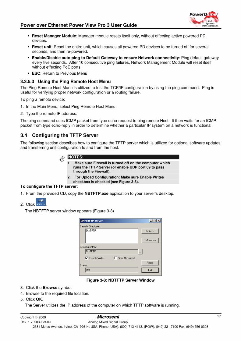
3.4 Configuring the TFTP Server
The following section describes how to configure the TFTP server which is utilized for optional software updates and transferring unit configuration to and from the host.
NOTES:
1. Make sure Firewall is turned off on the computer which runs the TFTP Server (or enable UDP port 69 to pass through the Firewall).
2. For Upload Configuration: Make sure Enable Writes
checkbox is checked (see Figure 3-8).
To configure the TFTP server:
1. From the provided CD, copy the NBTFTP.exe application to your server’s desktop.
2. Click .
The NBTFTP server window appears (Figure 3-8)
Figure 3-8: NBTFTP Server Window
3. Click the Browse symbol.
4. Browse to the required file location.
5. Click OK.
The Server utilizes the IP address of the computer on which TFTP software is running.

Power over Ethernet Power View Pro 3 User Guide
Copyright 2009 Microsemi Rev. 1.7, 203-Oct-09 Analog Mixed Signal Group
2381 Morse Avenue, Irvine, CA 92614, USA; Phone (USA): (800) 713-4113, (ROW): (949) 221-7100 Fax: (949) 756-0308
18
4 Web Interface Description The Web Interface provides complete monitoring, control and configuration of PowerDsine’s Power over Ethernet (PoE) products. The Web interface is user friendly and presents graphical elements of the actual device in addition to information tables.
4.1 Overview
The system provides the follows features:
� View Midspan configuration
� Midspan configuration
� Receive information on managed PD devices properties such as power consumption, class, etc.
The Web Interface has two authorization levels (see System Configuration Security, page 45):
� User: A remote user can access only those web pages which are located under the View menu.
� Administrator: A remote user has full access to all web pages.
4.2 Opening Screen
Browse to the Midspan IP address. The Main Window (Opening screen) appears (Figure 4-1). The Opening screen features three main menus:
� View menu: Used to view status, network configuration and product information.
� System Configuration menu: Enables system configuration (network, SNMP, security, RADIUS, UPS power management, product parameters and maintenance (password protection).
� Port Configuration menu: Enables enabling/disabling of ports, allocation of power, setting of priorities, and weekly based schedule automatic PoE ports activation/deactivation.
Figure 4-1: Power View Pro Main Window
4.3 View Menu
The View menu is used to view the following categories (see Figure 4-2):
� System status
� Configuration summary
� Product information
The View menu differs according to the model being used:
� View Status Screen (65xx, 65xxG, 80xx Midspan Series)
� View - Status Screen (70xxG Mid Power Midspan Series
� View - Status Screen (90xxG High Power Midspan Series
Power over Ethernet Power View Pro 3 User Guide
Copyright 2009 Microsemi Rev. 1.7, 203-Oct-09 Analog Mixed Signal Group
2381 Morse Avenue, Irvine, CA 92614, USA; Phone (USA): (800) 713-4113, (ROW): (949) 221-7100 Fax: (949) 756-0308
19
Figure 4-2: View Menu
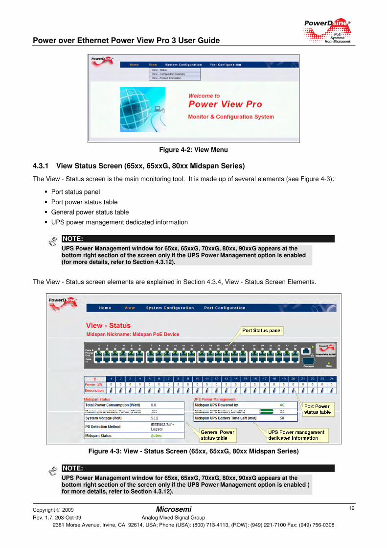
4.3.1 View Status Screen (65xx, 65xxG, 80xx Midspan Series)
The View - Status screen is the main monitoring tool. It is made up of several elements (see Figure 4-3):
� Port status panel
� Port power status table
� General power status table
� UPS power management dedicated information
The View - Status screen elements are explained in Section 4.3.4, View - Status Screen Elements.
Figure 4-3: View - Status Screen (65xx, 65xxG, 80xx Midspan Series)
NOTE:
UPS Power Management window for 65xx, 65xxG, 70xxG, 80xx, 90xxG appears at the bottom right section of the screen only if the UPS Power Management option is enabled (for more details, refer to Section 4.3.12).
NOTE:
UPS Power Management window for 65xx, 65xxG, 70xxG, 80xx, 90xxG appears at the bottom right section of the screen only if the UPS Power Management option is enabled ( for more details, refer to Section 4.3.12).
Power over Ethernet Power View Pro 3 User Guide
Copyright 2009 Microsemi Rev. 1.7, 203-Oct-09 Analog Mixed Signal Group
2381 Morse Avenue, Irvine, CA 92614, USA; Phone (USA): (800) 713-4113, (ROW): (949) 221-7100 Fax: (949) 756-0308
20
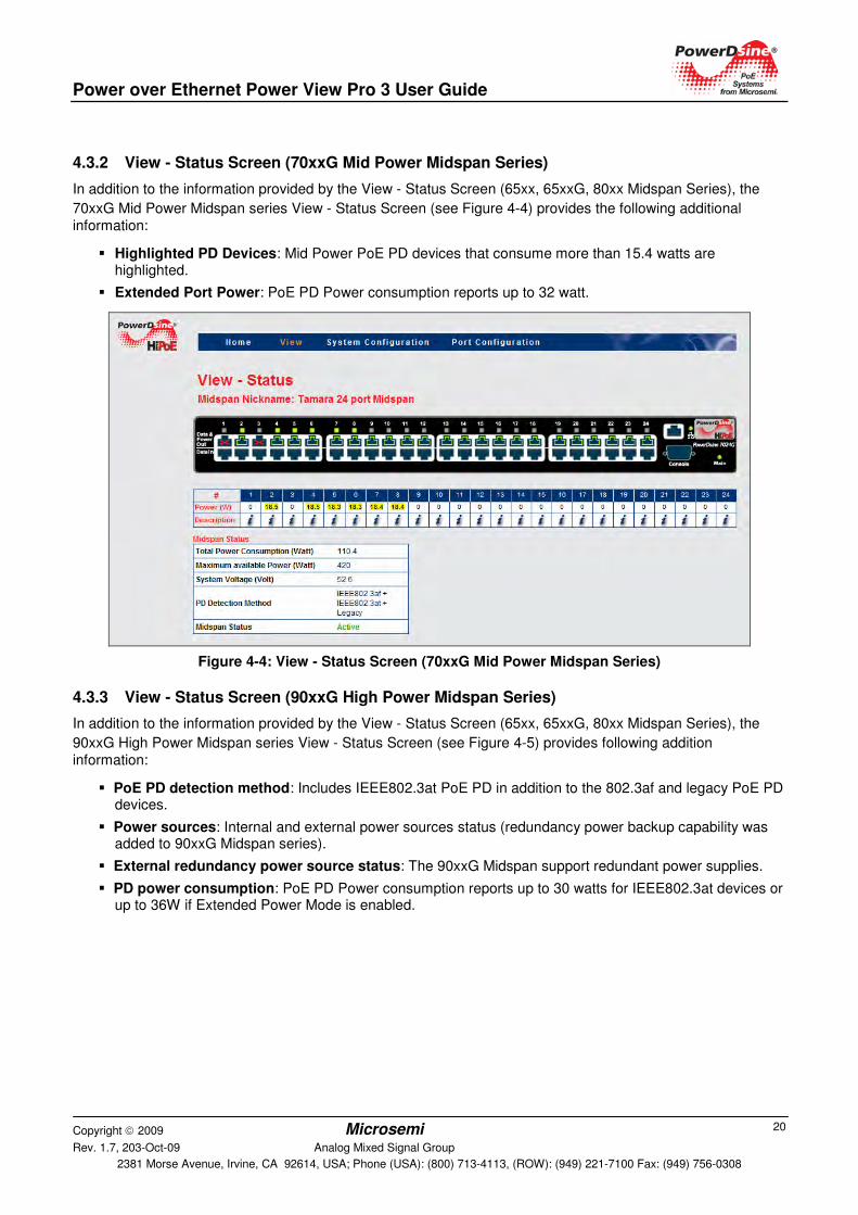
4.3.2 View - Status Screen (70xxG Mid Power Midspan Series)
In addition to the information provided by the View - Status Screen (65xx, 65xxG, 80xx Midspan Series), the
70xxG Mid Power Midspan series View - Status Screen (see Figure 4-4) provides the following additional information:
� Highlighted PD Devices: Mid Power PoE PD devices that consume more than 15.4 watts are highlighted.
� Extended Port Power: PoE PD Power consumption reports up to 32 watt.
Figure 4-4: View - Status Screen (70xxG Mid Power Midspan Series)
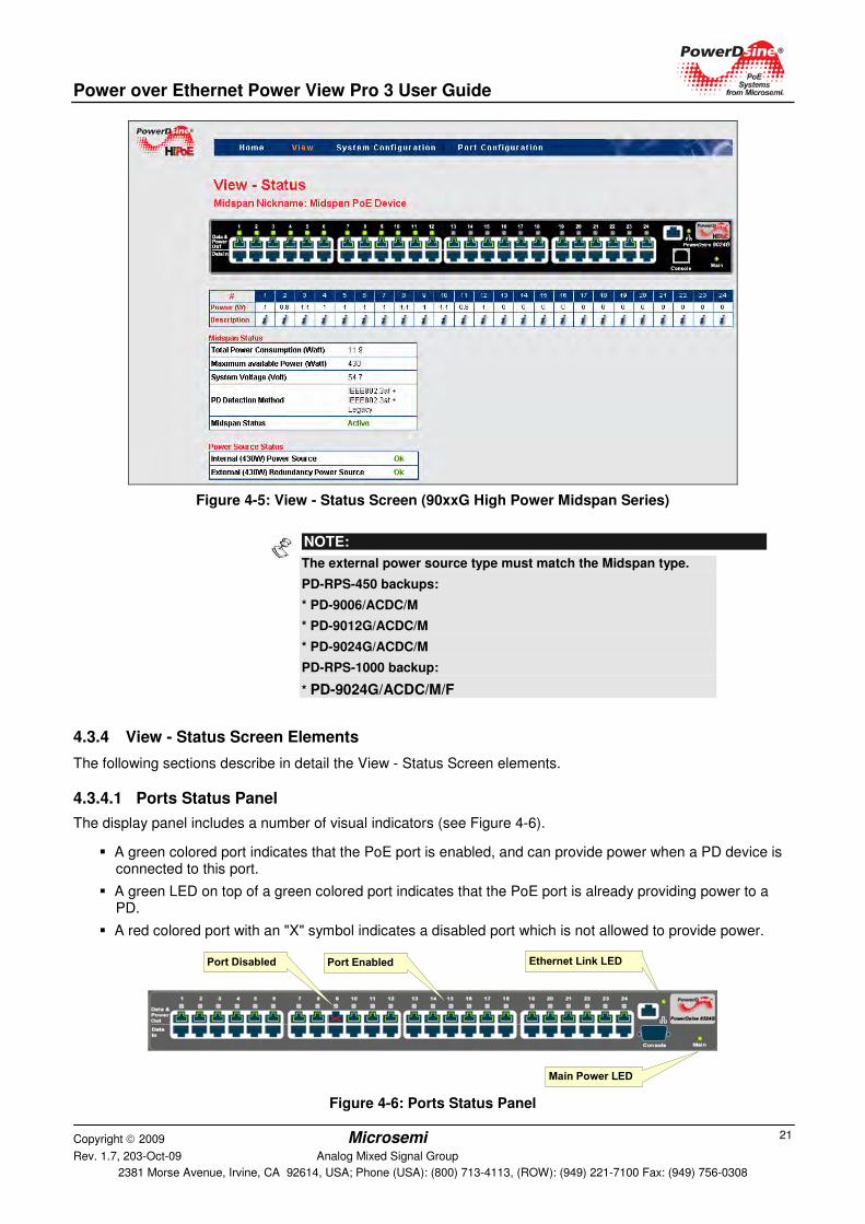
4.3.3 View - Status Screen (90xxG High Power Midspan Series)
In addition to the information provided by the View - Status Screen (65xx, 65xxG, 80xx Midspan Series), the
90xxG High Power Midspan series View - Status Screen (see Figure 4-5) provides following addition information:
� PoE PD detection method: Includes IEEE802.3at PoE PD in addition to the 802.3af and legacy PoE PD devices.
� Power sources: Internal and external power sources status (redundancy power backup capability was added to 90xxG Midspan series).
� External redundancy power source status: The 90xxG Midspan support redundant power supplies.
� PD power consumption: PoE PD Power consumption reports up to 30 watts for IEEE802.3at devices or up to 36W if Extended Power Mode is enabled.
Power over Ethernet Power View Pro 3 User Guide
Copyright 2009 Microsemi Rev. 1.7, 203-Oct-09 Analog Mixed Signal Group
2381 Morse Avenue, Irvine, CA 92614, USA; Phone (USA): (800) 713-4113, (ROW): (949) 221-7100 Fax: (949) 756-0308
21
Figure 4-5: View - Status Screen (90xxG High Power Midspan Series)
4.3.4 View - Status Screen Elements
The following sections describe in detail the View - Status Screen elements.
4.3.4.1 Ports Status Panel
The display panel includes a number of visual indicators (see Figure 4-6).
� A green colored port indicates that the PoE port is enabled, and can provide power when a PD device is connected to this port.
� A green LED on top of a green colored port indicates that the PoE port is already providing power to a PD.
� A red colored port with an "X" symbol indicates a disabled port which is not allowed to provide power.
Port Disabled Port Enabled
Main Power LED
Ethernet Link LED
Figure 4-6: Ports Status Panel
NOTE:
The external power source type must match the Midspan type.
PD-RPS-450 backups:
* PD-9006/ACDC/M
* PD-9012G/ACDC/M
* PD-9024G/ACDC/M
PD-RPS-1000 backup:
* PD-9024G/ACDC/M/F
Power over Ethernet Power View Pro 3 User Guide
Copyright 2009 Microsemi Rev. 1.7, 203-Oct-09 Analog Mixed Signal Group
2381 Morse Avenue, Irvine, CA 92614, USA; Phone (USA): (800) 713-4113, (ROW): (949) 221-7100 Fax: (949) 756-0308
22
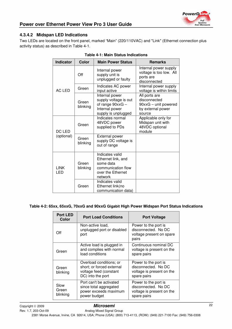
4.3.4.2 Midspan LED Indications
Two LEDs are located on the front panel, marked “Main” (220/110VAC) and "Link" (Ethernet connection plus
activity status) as described in Table 4 -1.
Table 4-1: Main Status Indications
Indicator Color Main Power Status Remarks
Off Internal power supply unit is unplugged or faulty
Internal power supply voltage is too low. All ports are disconnected
Green Indicates AC power input active
Internal power supply voltage is within limits AC LED
Green blinking
Internal power supply voltage is out of range 90xxG – Internal power supply is unplugged
All ports are disconnected 90xxG – unit powered by external power source
Green
Indicates normal 48VDC power supplied to PDs
Applicable only for Midspan unit with 48VDC optional module DC LED
(optional) Green blinking
External power supply DC voltage is out of range
Green blinking
Indicates valid Ethernet link, and some data communication flow over the Ethernet network
LINK LED
Green Indicates valid Ethernet link(no communication data)
Table 4-2: 65xx, 65xxG, 70xxG and 90xxG Gigabit High Power Midspan Port Status Indications
Port LED Color
Port Load Conditions Port Voltage
Off
Non-active load, unplugged port or disabled port
Power to the port is disconnected. No DC voltage present on spare pairs
Green
Active load is plugged in and complies with normal load conditions
Continuous nominal DC voltage is present on the spare pairs
Green blinking
Overload conditions; or short; or forced external voltage feed (constant DC) into the port
Power to the port is disconnected. No DC voltage is present on the spare pairs
Slow Green blinking
Port can't be activated since total aggregated power exceeds maximum power budget
Power to the port is disconnected. No DC voltage is present on the spare pairs
Power over Ethernet Power View Pro 3 User Guide
Copyright 2009 Microsemi Rev. 1.7, 203-Oct-09 Analog Mixed Signal Group
2381 Morse Avenue, Irvine, CA 92614, USA; Phone (USA): (800) 713-4113, (ROW): (949) 221-7100 Fax: (949) 756-0308
23
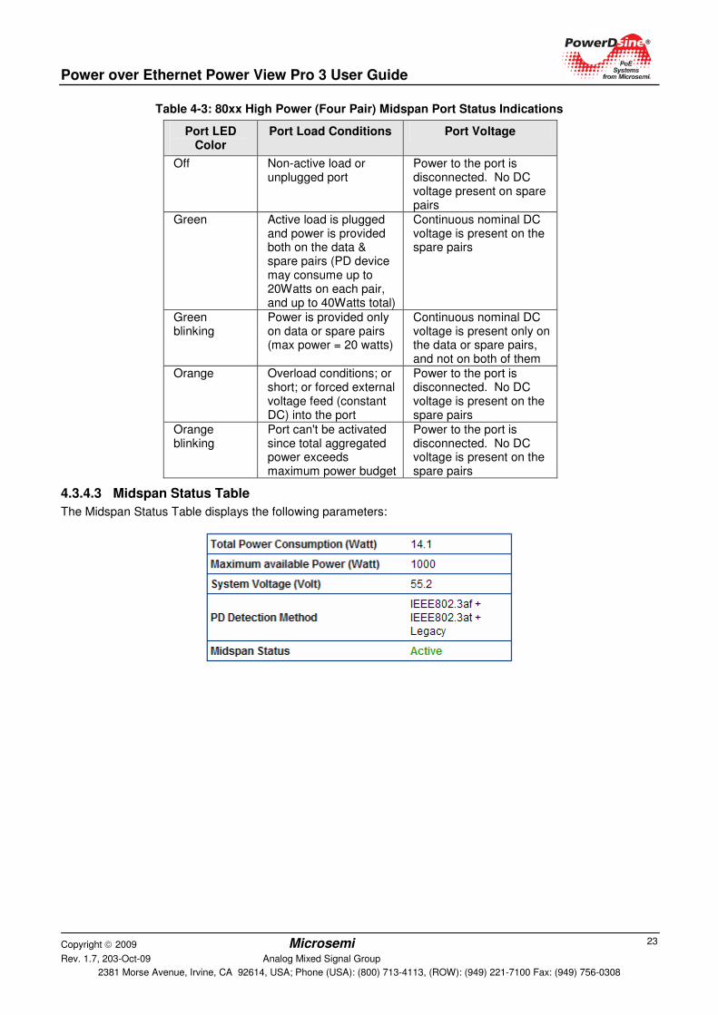
Table 4-3: 80xx High Power (Four Pair) Midspan Port Status Indications
Port LED Color
Port Load Conditions Port Voltage
Off Non-active load or unplugged port
Power to the port is disconnected. No DC voltage present on spare pairs
Green Active load is plugged and power is provided both on the data & spare pairs (PD device may consume up to 20Watts on each pair, and up to 40Watts total)
Continuous nominal DC voltage is present on the spare pairs
Green blinking
Power is provided only on data or spare pairs (max power = 20 watts)
Continuous nominal DC voltage is present only on the data or spare pairs, and not on both of them
Orange Overload conditions; or short; or forced external voltage feed (constant DC) into the port
Power to the port is disconnected. No DC voltage is present on the spare pairs
Orange blinking
Port can't be activated since total aggregated power exceeds maximum power budget
Power to the port is disconnected. No DC voltage is present on the spare pairs
4.3.4.3 Midspan Status Table
The Midspan Status Table displays the following parameters:
Power over Ethernet Power View Pro 3 User Guide
Copyright 2009 Microsemi Rev. 1.7, 203-Oct-09 Analog Mixed Signal Group
2381 Morse Avenue, Irvine, CA 92614, USA; Phone (USA): (800) 713-4113, (ROW): (949) 221-7100 Fax: (949) 756-0308
24
Table 4-4: Midspan Status Table Details
Parameter Description
Total Power Consumption
Total power consumed by all PDs
Maximum available Power
Maximum available Power for all external PoE devices
System Voltage Voltage level supplied to PDs
PD Detection Method
Detection method selected by the user from the System Configuration - Product Parameters menu (see System Configuration Product Parameters - 65xx, 65xxG, 70xxG, 80xx Family,
section 4.3.13)
Midspan Status Midspan status display with the following options:
• Active: normal operation
• Midspan has no firmware
• Internal Comm. Failure
• Midspan firmware update
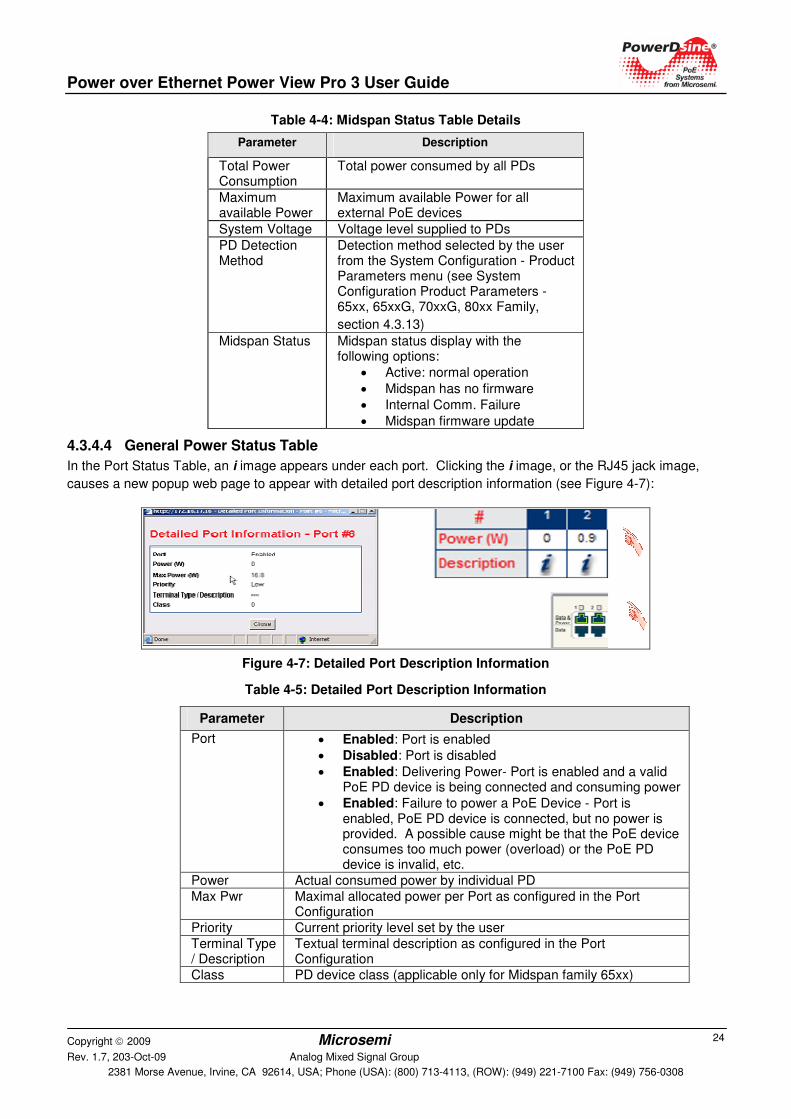
4.3.4.4 General Power Status Table
In the Port Status Table, an i image appears under each port. Clicking the i image, or the RJ45 jack image,
causes a new popup web page to appear with detailed port description information (see Figure 4-7):
Figure 4-7: Detailed Port Description Information
Table 4-5: Detailed Port Description Information
Parameter Description
Port • Enabled: Port is enabled
• Disabled: Port is disabled
• Enabled: Delivering Power- Port is enabled and a valid PoE PD device is being connected and consuming power
• Enabled: Failure to power a PoE Device - Port is enabled, PoE PD device is connected, but no power is provided. A possible cause might be that the PoE device consumes too much power (overload) or the PoE PD device is invalid, etc.
Power Actual consumed power by individual PD
Max Pwr Maximal allocated power per Port as configured in the Port Configuration
Priority Current priority level set by the user
Terminal Type / Description
Textual terminal description as configured in the Port Configuration
Class PD device class (applicable only for Midspan family 65xx)
Power over Ethernet Power View Pro 3 User Guide
Copyright 2009 Microsemi Rev. 1.7, 203-Oct-09 Analog Mixed Signal Group
2381 Morse Avenue, Irvine, CA 92614, USA; Phone (USA): (800) 713-4113, (ROW): (949) 221-7100 Fax: (949) 756-0308
25
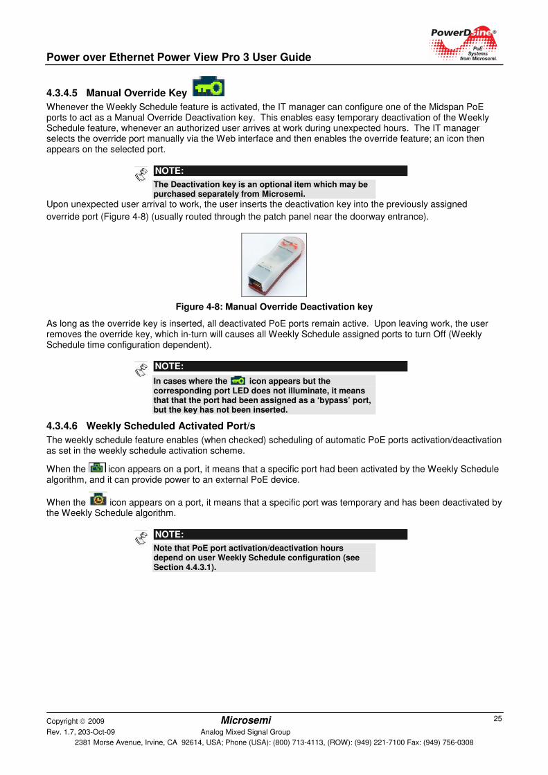
4.3.4.5 Manual Override Key
Whenever the Weekly Schedule feature is activated, the IT manager can configure one of the Midspan PoE ports to act as a Manual Override Deactivation key. This enables easy temporary deactivation of the Weekly Schedule feature, whenever an authorized user arrives at work during unexpected hours. The IT manager selects the override port manually via the Web interface and then enables the override feature; an icon then appears on the selected port.
NOTE:
The Deactivation key is an optional item which may be purchased separately from Microsemi.
Upon unexpected user arrival to work, the user inserts the deactivation key into the previously assigned
override port (Figure 4-8) (usually routed through the patch panel near the doorway entrance).
Figure 4-8: Manual Override Deactivation key
As long as the override key is inserted, all deactivated PoE ports remain active. Upon leaving work, the user removes the override key, which in-turn will causes all Weekly Schedule assigned ports to turn Off (Weekly Schedule time configuration dependent).
NOTE:
In cases where the icon appears but the corresponding port LED does not illuminate, it means that that the port had been assigned as a ‘bypass’ port, but the key has not been inserted.
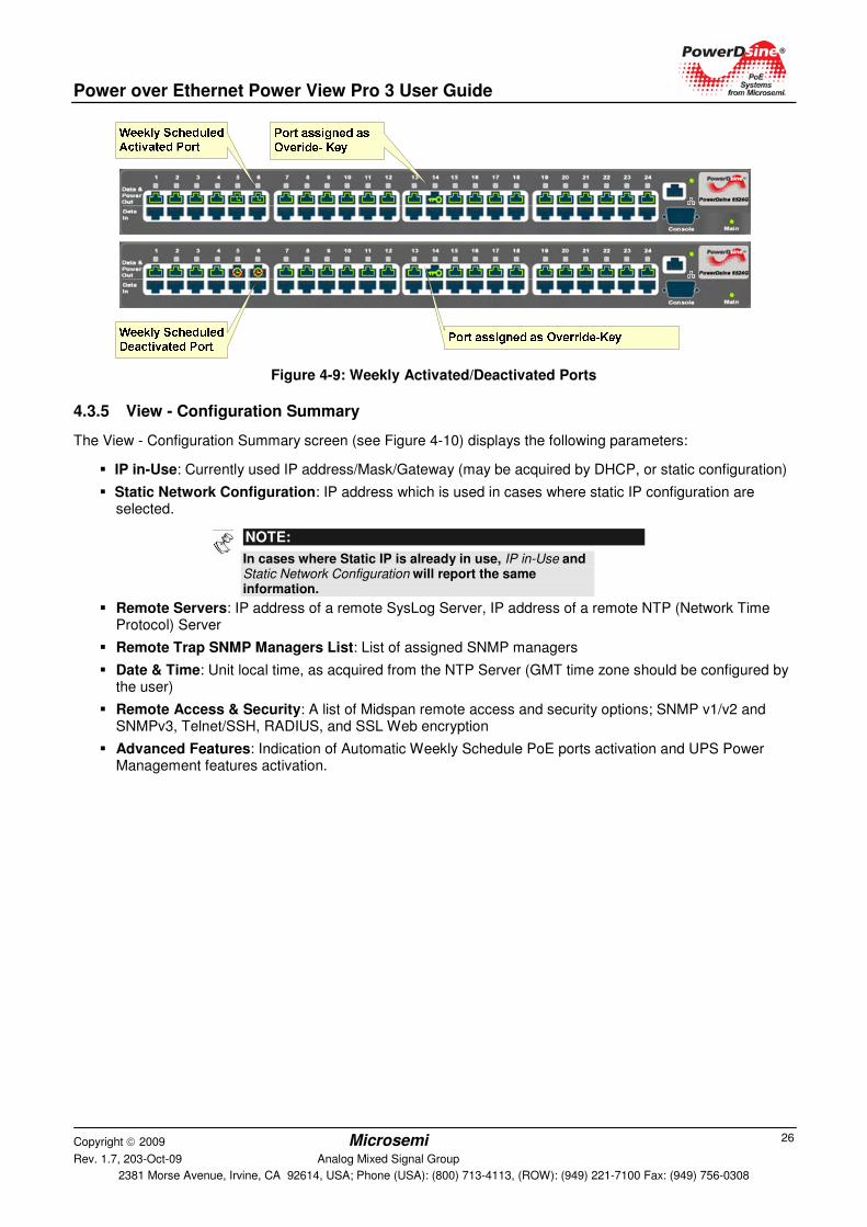
4.3.4.6 Weekly Scheduled Activated Port/s
The weekly schedule feature enables (when checked) scheduling of automatic PoE ports activation/deactivation as set in the weekly schedule activation scheme.
When the icon appears on a port, it means that a specific port had been activated by the Weekly Schedule algorithm, and it can provide power to an external PoE device.
When the icon appears on a port, it means that a specific port was temporary and has been deactivated by the Weekly Schedule algorithm.
NOTE:
Note that PoE port activation/deactivation hours depend on user Weekly Schedule configuration (see Section 4.4.3.1).
Power over Ethernet Power View Pro 3 User Guide
Copyright 2009 Microsemi Rev. 1.7, 203-Oct-09 Analog Mixed Signal Group
2381 Morse Avenue, Irvine, CA 92614, USA; Phone (USA): (800) 713-4113, (ROW): (949) 221-7100 Fax: (949) 756-0308
26
Figure 4-9: Weekly Activated/Deactivated Ports
4.3.5 View - Configuration Summary
The View - Configuration Summary screen (see Figure 4-10) displays the following parameters:
� IP in-Use: Currently used IP address/Mask/Gateway (may be acquired by DHCP, or static configuration)
� Static Network Configuration: IP address which is used in cases where static IP configuration are selected.
NOTE:
In cases where Static IP is already in use, IP in-Use and Static Network Configuration will report the same information.
� Remote Servers: IP address of a remote SysLog Server, IP address of a remote NTP (Network Time Protocol) Server
� Remote Trap SNMP Managers List: List of assigned SNMP managers
� Date & Time: Unit local time, as acquired from the NTP Server (GMT time zone should be configured by the user)
� Remote Access & Security: A list of Midspan remote access and security options; SNMP v1/v2 and SNMPv3, Telnet/SSH, RADIUS, and SSL Web encryption
� Advanced Features: Indication of Automatic Weekly Schedule PoE ports activation and UPS Power Management features activation.

Power over Ethernet Power View Pro 3 User Guide
Copyright 2009 Microsemi Rev. 1.7, 203-Oct-09 Analog Mixed Signal Group
2381 Morse Avenue, Irvine, CA 92614, USA; Phone (USA): (800) 713-4113, (ROW): (949) 221-7100 Fax: (949) 756-0308
27
Figure 4-10: View - Configuration Summary Screen
4.3.5.1 IP in-Use
IP in-use window displays the current IP address being used with the following parameters (Figure 4-11):
Figure 4-11: IP in-Use Window
Table 4-6: IP in User Parameters
Parameter Description
Obtain IP by DHCP
Indicates how the IP is obtained as previously set by the user (see System Configuration Network Screen, page 32).
IP Address IP address, numerical address which indicates a particular computer within a network
IP Mask
The definition of the network portion of the IP address. This location must be configured in such a way that all IP addresses up to and including the local gateway are allowed.
Default Gateway
The IP address of the local Gateway, which enables communication settings to other LAN segments.
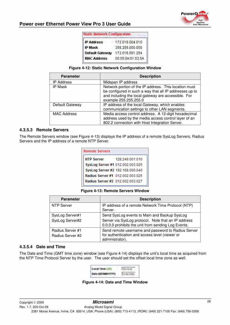
4.3.5.2 Static Network Configuration
The Static Network Configuration window (see Figure 4-12) displays network configuration in cases where Static IP is selected (and not DHCP). When the unit is configured as a Static IP, both IP-In Use and Static configuration tables are identical.
Power over Ethernet Power View Pro 3 User Guide
Copyright 2009 Microsemi Rev. 1.7, 203-Oct-09 Analog Mixed Signal Group
2381 Morse Avenue, Irvine, CA 92614, USA; Phone (USA): (800) 713-4113, (ROW): (949) 221-7100 Fax: (949) 756-0308
28
Figure 4-12: Static Network Configuration Window
Parameter Description
IP Address Midspan IP address
IP Mask
Network portion of the IP address. This location must be configured in such a way that all IP addresses up to and including the local gateway are accessible. For example 255.255.255.0
Default Gateway IP address of the local Gateway, which enables communication settings to other LAN segments.
MAC Address Media access control address. A 12-digit hexadecimal address used by the media access control layer of an 802.2 connection with Host Integration Server.
4.3.5.3 Remote Servers
The Remote Servers window (see Figure 4-13) displays the IP address of a remote SysLog Servers, Radius Servers and the IP address of a remote NTP Server.
Figure 4-13: Remote Servers Window
Parameter Description
NTP Server IP address of a remote Network Time Protocol (NTP) Server.
SysLog Server#1
SysLog Server#2
Send SysLog events to Main and Backup SysLog
Server via SysLog protocol. Note that an IP address
0.0.0.0 prohibits the unit from sending Log Events.
Radius Server #1
Radius Server #2
Send remote username and password to Radius Server for authentication and access level (viewer or administrator).
4.3.5.4 Date and Time
The Date and Time (GMT time zone) window (see Figure 4-14) displays the unit’s local time as acquired from the NTP Time Protocol Server by the user. The user should set the offset local time zone as well.
Figure 4-14: Date and Time Window
Power over Ethernet Power View Pro 3 User Guide
Copyright 2009 Microsemi Rev. 1.7, 203-Oct-09 Analog Mixed Signal Group
2381 Morse Avenue, Irvine, CA 92614, USA; Phone (USA): (800) 713-4113, (ROW): (949) 221-7100 Fax: (949) 756-0308
29
Parameter Description
Local Time (GMT)
Time (HH:MM:SS) as acquired from the NTP Server
Date (D/M/Y) Date (DD/MM/YYYY) as acquired from the NTP Server
NOTES: 1. When the appropriate time and date are acquired from
the NTP server, an OK indication appears. Alongside the Time Zone Offset from GMT window in the System Configuration - Weekly Schedule Ports Activation menu
(refer to Section 4.4.3.1) If the system fails to acquire the appropriate time and date ‘FAIL’ indication appears instead!
2. If the unit fails to acquire time from NTP Server, it displays the elapsed time starting from 1/1/2005
3. If time and date are not acquired, Weekly Schedule functionality will not function!
4. If offset local time zone has been improperly set by the user the Weekly Schedule feature will function not in the appropriate hours!
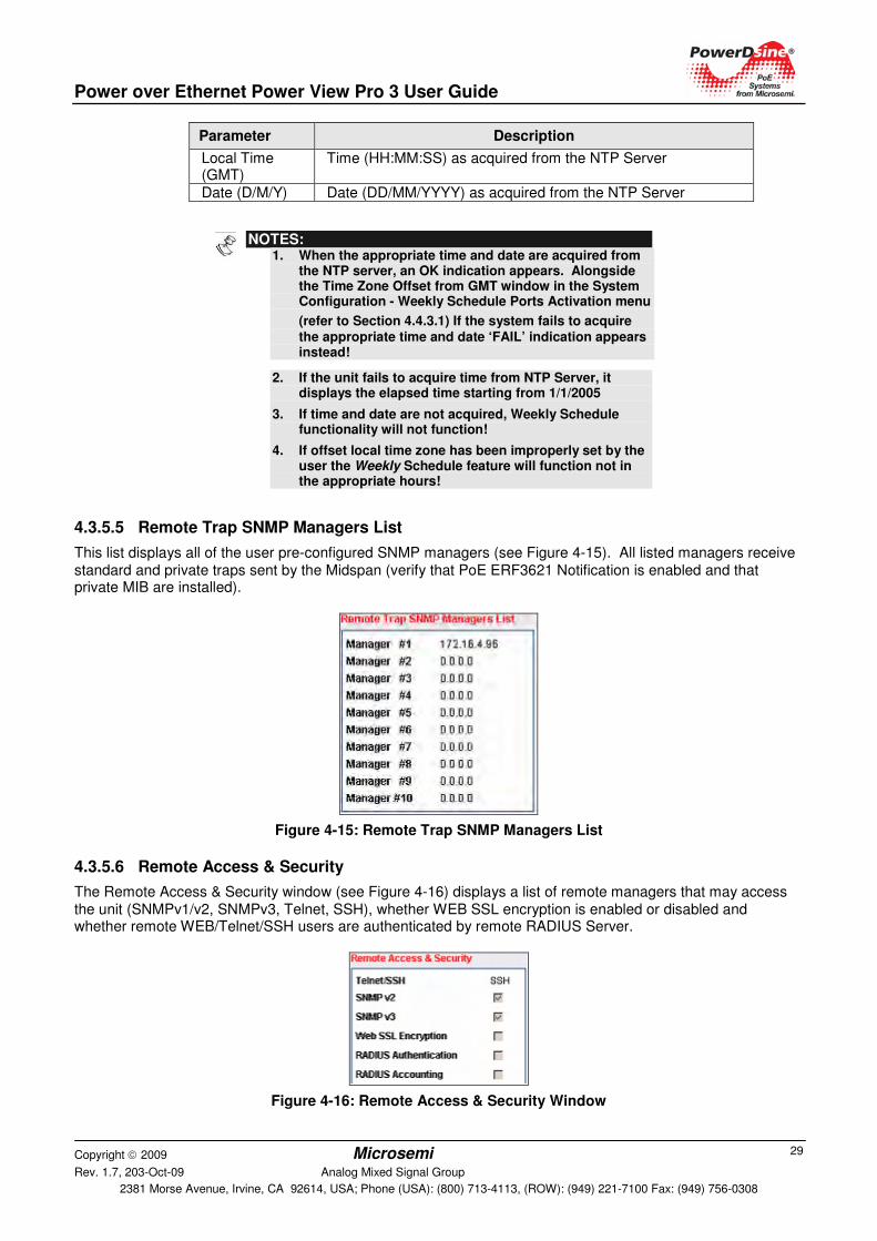
4.3.5.5 Remote Trap SNMP Managers List
This list displays all of the user pre-configured SNMP managers (see Figure 4-15). All listed managers receive standard and private traps sent by the Midspan (verify that PoE ERF3621 Notification is enabled and that private MIB are installed).
Figure 4-15: Remote Trap SNMP Managers List
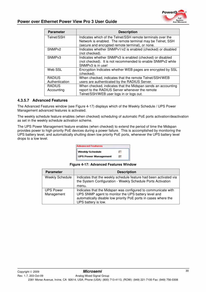
4.3.5.6 Remote Access & Security
The Remote Access & Security window (see Figure 4-16) displays a list of remote managers that may access the unit (SNMPv1/v2, SNMPv3, Telnet, SSH), whether WEB SSL encryption is enabled or disabled and whether remote WEB/Telnet/SSH users are authenticated by remote RADIUS Server.
Figure 4-16: Remote Access & Security Window
Power over Ethernet Power View Pro 3 User Guide
Copyright 2009 Microsemi Rev. 1.7, 203-Oct-09 Analog Mixed Signal Group
2381 Morse Avenue, Irvine, CA 92614, USA; Phone (USA): (800) 713-4113, (ROW): (949) 221-7100 Fax: (949) 756-0308
30
Parameter Description
Telnet/SSH Indicates which of the Telnet/SSH remote terminals over the Network is enabled. The remote terminal may be Telnet, SSH (secure and encrypted remote terminal), or none.
SNMPv2 Indicates whether SNMPv1/v2 is enabled (checked) or disabled (not checked).
SNMPv3 Indicates whether SNMPv3 is enabled (checked) or disabled (not checked). It is not recommended to enable SNMPv2 while SNMPv3 is in use!
Web SSL Encryption Indicates whether WEB pages are encrypted by SSL (checked).
RADIUS Authentication
When checked, indicates that the remote Telnet/SSH/WEB users are authenticated by the RADIUS Server.
RADIUS Accounting
When checked, indicates that the Midspan sends an accounting report to the RADIUS Server whenever the remote Telnet/SSH/WEB user logs in or logs out.
4.3.5.7 Advanced Features
The Advanced Features window (see Figure 4-17) displays which of the Weekly Schedule / UPS Power Management advanced features is activated.
The weekly schedule feature enables (when checked) scheduling of automatic PoE ports activation/deactivation as set in the weekly schedule activation scheme.
The UPS Power Management feature enables (when checked) to extend the period of time the Midspan provides power to high priority PoE devices during a power failure. This is accomplished by monitoring the UPS battery level, and automatically shutting down low priority PoE ports, whenever the UPS battery level drops to a low level.
Figure 4-17: Advanced Features Window
Parameter Description
Weekly Schedule Indicates that the weekly schedule feature had been activated via the System Configuration - Weekly Schedule Ports Activation
menu.
UPS Power Management
Indicates that the Midspan was configured to communicate with UPS SNMP agent to monitor the UPS battery level and automatically disable low priority PoE ports in cases where the UPS battery is low.
Power over Ethernet Power View Pro 3 User Guide
Copyright 2009 Microsemi Rev. 1.7, 203-Oct-09 Analog Mixed Signal Group
2381 Morse Avenue, Irvine, CA 92614, USA; Phone (USA): (800) 713-4113, (ROW): (949) 221-7100 Fax: (949) 756-0308
31
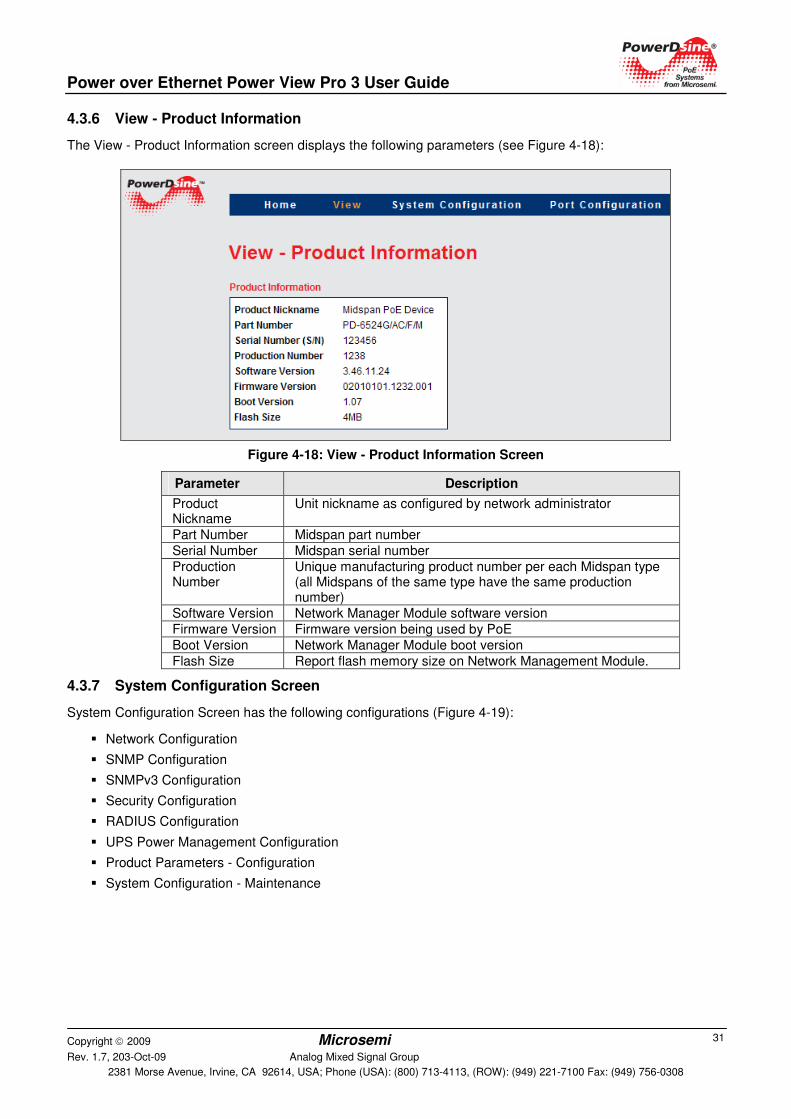
4.3.6 View - Product Information
The View - Product Information screen displays the following parameters (see Figure 4-18):
Figure 4-18: View - Product Information Screen
Parameter Description
Product Nickname
Unit nickname as configured by network administrator
Part Number Midspan part number
Serial Number Midspan serial number
Production Number
Unique manufacturing product number per each Midspan type (all Midspans of the same type have the same production number)
Software Version Network Manager Module software version
Firmware Version Firmware version being used by PoE
Boot Version Network Manager Module boot version
Flash Size Report flash memory size on Network Management Module.
4.3.7 System Configuration Screen
System Configuration Screen has the following configurations (Figure 4-19):
� Network Configuration
� SNMP Configuration
� SNMPv3 Configuration
� Security Configuration
� RADIUS Configuration
� UPS Power Management Configuration
� Product Parameters - Configuration
� System Configuration - Maintenance
Power over Ethernet Power View Pro 3 User Guide
Copyright 2009 Microsemi Rev. 1.7, 203-Oct-09 Analog Mixed Signal Group
2381 Morse Avenue, Irvine, CA 92614, USA; Phone (USA): (800) 713-4113, (ROW): (949) 221-7100 Fax: (949) 756-0308
32
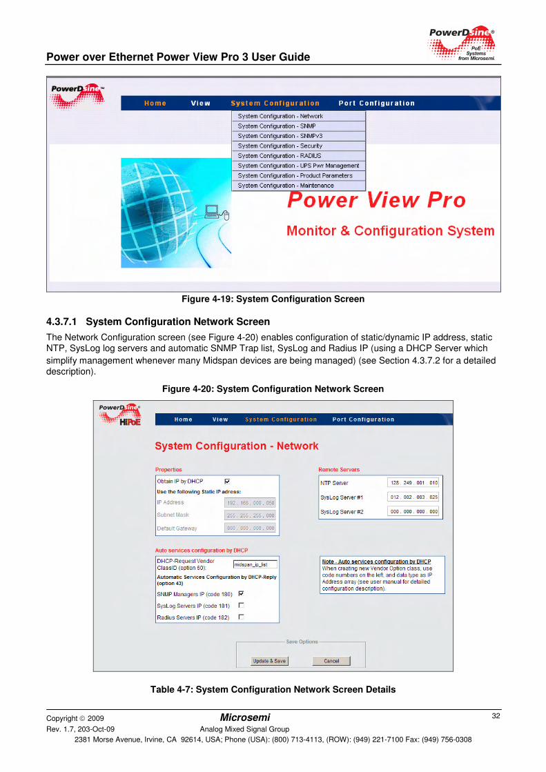
Figure 4-19: System Configuration Screen
4.3.7.1 System Configuration Network Screen
The Network Configuration screen (see Figure 4-20) enables configuration of static/dynamic IP address, static NTP, SysLog log servers and automatic SNMP Trap list, SysLog and Radius IP (using a DHCP Server which
simplify management whenever many Midspan devices are being managed) (see Section 4.3.7.2 for a detailed description).
Figure 4-20: System Configuration Network Screen
Table 4-7: System Configuration Network Screen Details
Power over Ethernet Power View Pro 3 User Guide
Copyright 2009 Microsemi Rev. 1.7, 203-Oct-09 Analog Mixed Signal Group
2381 Morse Avenue, Irvine, CA 92614, USA; Phone (USA): (800) 713-4113, (ROW): (949) 221-7100 Fax: (949) 756-0308
33
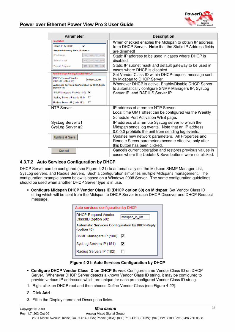
Parameter Description
When checked enables the Midspan to obtain IP address from DHCP Server. Note that the Static IP Address fields are dimmed!
Static IP address to be used in cases where DHCP is disabled.
Static IP subnet mask and default gateway to be used in cases where DHCP is disabled.
Set Vendor Class ID within DHCP-request message sent by Midspan to DHCP Server.
Whenever DHCP is active, Enable/Disable DHCP Server to automatically configure SNMP Managers IP, SysLog Server IP, and RADIUS Server IP.
NTP Server IP address of a remote NTP Server Local time GMT offset can be configured via the Weekly
Schedule Port Activation WEB page.
SysLog Server #1 SysLog Server #2
IP address of a remote SysLog server to which the Midspan sends log events. Note that an IP address 0.0.0.0 prohibits the unit from sending log events.
Updates new network parameters. All Properties and Remote Server parameters become effective only after this button has been clicked.
Cancels current operation and restores previous values in cases where the Update & Save buttons were not clicked.
4.3.7.2 Auto Services Configuration by DHCP
DHCP Server can be configured (see Figure 4-21) to automatically set the Midspan SNMP Manager List, SysLog servers, and Radius Servers. Such a configuration simplifies multiple Midspans management. The configuration example shown below is based on a Windows 2008 Server. The same configuration guidelines should be used when another DHCP Server type is in use.
� Configure Midspan DHCP Vendor Class ID (DHCP option 60) on Midspan: Set Vendor Class ID string which will be sent from the Midspan to DHCP Server in each DHCP-Discover and DHCP-Request message.
Figure 4-21: Auto Services Configuration by DHCP
� Configure DHCP Vendor Class ID on DHCP Server: Configure same Vendor Class ID on DHCP Server. Whenever DHCP Server detects a known Vendor Class ID string, it may be configured to provide various IP addresses which are unique for each pre configured Vendor Class ID string.
1. Right click on DHCP root and then choose Define Vendor Class (see Figure 4-22).
2. Click Add.
3. Fill in the Display name and Description fields.
Power over Ethernet Power View Pro 3 User Guide
Copyright 2009 Microsemi Rev. 1.7, 203-Oct-09 Analog Mixed Signal Group
2381 Morse Avenue, Irvine, CA 92614, USA; Phone (USA): (800) 713-4113, (ROW): (949) 221-7100 Fax: (949) 756-0308
34
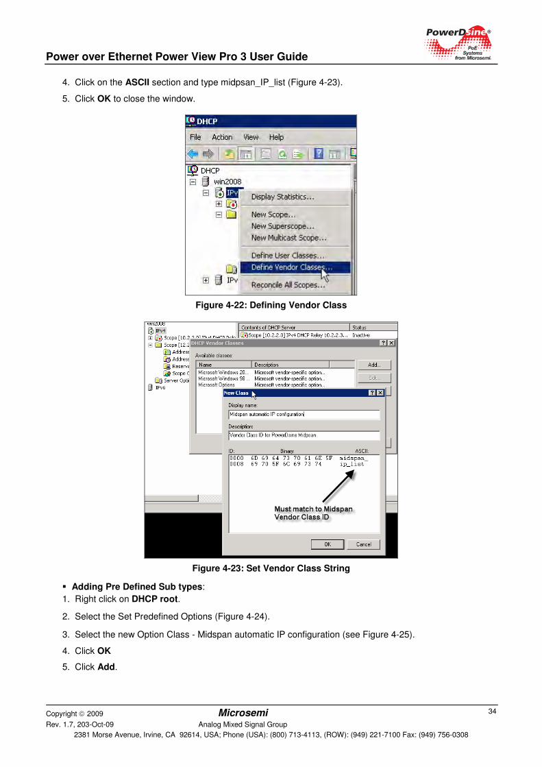
4. Click on the ASCII section and type midpsan_IP_list (Figure 4-23).
5. Click OK to close the window.
Figure 4-22: Defining Vendor Class
Figure 4-23: Set Vendor Class String
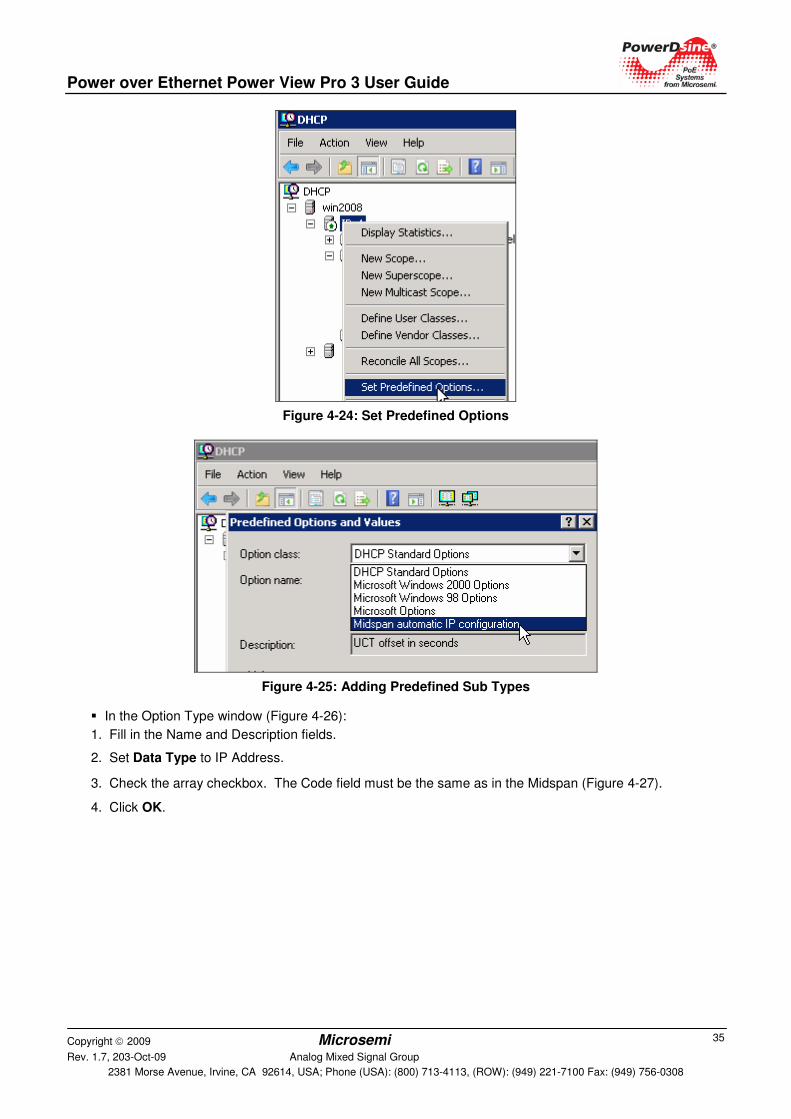
� Adding Pre Defined Sub types:
1. Right click on DHCP root.
2. Select the Set Predefined Options (Figure 4-24).
3. Select the new Option Class - Midspan automatic IP configuration (see Figure 4-25).
4. Click OK
5. Click Add.
Power over Ethernet Power View Pro 3 User Guide
Copyright 2009 Microsemi Rev. 1.7, 203-Oct-09 Analog Mixed Signal Group
2381 Morse Avenue, Irvine, CA 92614, USA; Phone (USA): (800) 713-4113, (ROW): (949) 221-7100 Fax: (949) 756-0308
35
Figure 4-24: Set Predefined Options
Figure 4-25: Adding Predefined Sub Types
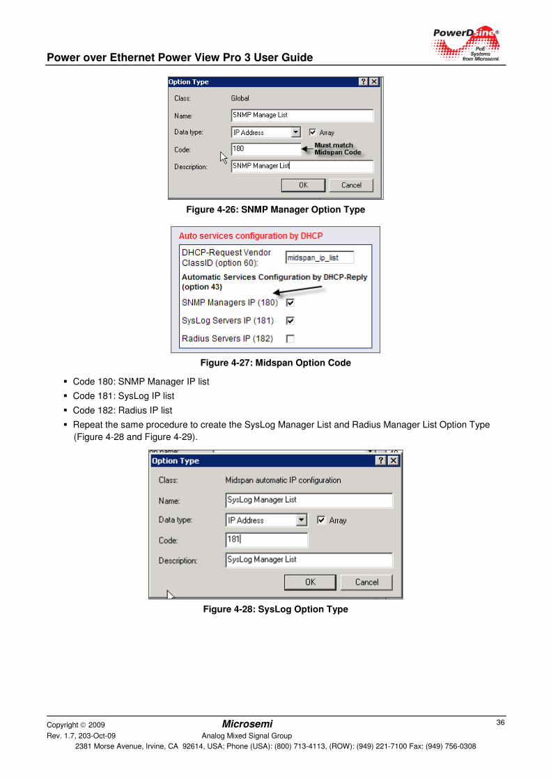
� In the Option Type window (Figure 4-26):
1. Fill in the Name and Description fields.
2. Set Data Type to IP Address.
3. Check the array checkbox. The Code field must be the same as in the Midspan (Figure 4-27).
4. Click OK.
Power over Ethernet Power View Pro 3 User Guide
Copyright 2009 Microsemi Rev. 1.7, 203-Oct-09 Analog Mixed Signal Group
2381 Morse Avenue, Irvine, CA 92614, USA; Phone (USA): (800) 713-4113, (ROW): (949) 221-7100 Fax: (949) 756-0308
36
Figure 4-26: SNMP Manager Option Type
Figure 4-27: Midspan Option Code
� Code 180: SNMP Manager IP list
� Code 181: SysLog IP list
� Code 182: Radius IP list
� Repeat the same procedure to create the SysLog Manager List and Radius Manager List Option Type
(Figure 4-28 and Figure 4-29).
Figure 4-28: SysLog Option Type
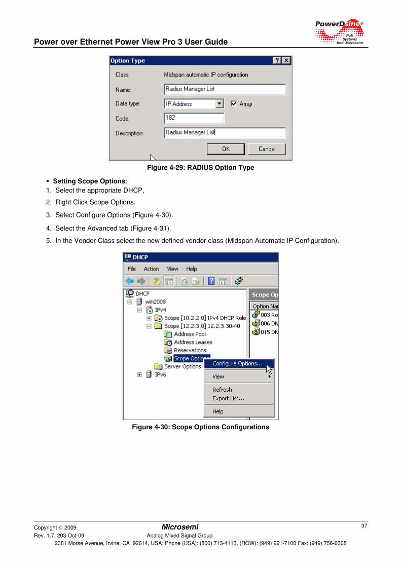
Power over Ethernet Power View Pro 3 User Guide
Copyright 2009 Microsemi Rev. 1.7, 203-Oct-09 Analog Mixed Signal Group
2381 Morse Avenue, Irvine, CA 92614, USA; Phone (USA): (800) 713-4113, (ROW): (949) 221-7100 Fax: (949) 756-0308
37
Figure 4-29: RADIUS Option Type
� Setting Scope Options:
1. Select the appropriate DHCP,
2. Right Click Scope Options.
3. Select Configure Options (Figure 4-30).
4. Select the Advanced tab (Figure 4-31).
5. In the Vendor Class select the new defined vendor class (Midspan Automatic IP Configuration).
Figure 4-30: Scope Options Configurations
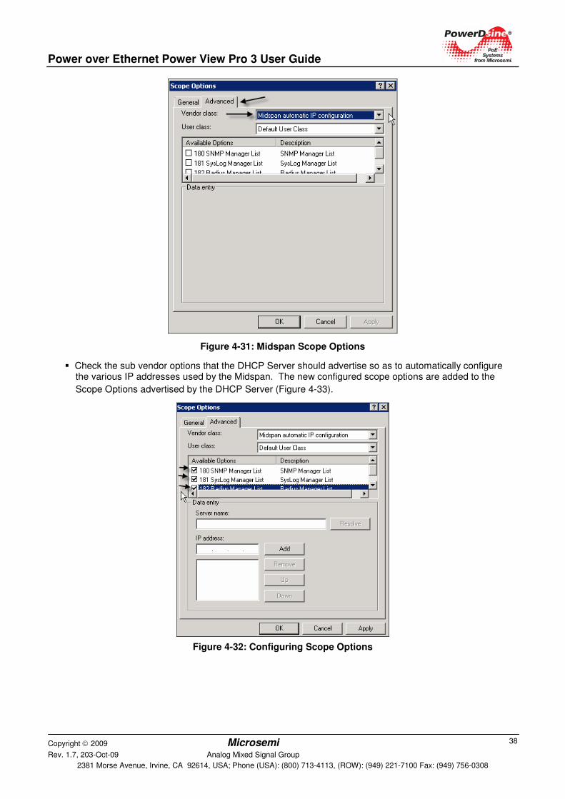
Power over Ethernet Power View Pro 3 User Guide
Copyright 2009 Microsemi Rev. 1.7, 203-Oct-09 Analog Mixed Signal Group
2381 Morse Avenue, Irvine, CA 92614, USA; Phone (USA): (800) 713-4113, (ROW): (949) 221-7100 Fax: (949) 756-0308
38
Figure 4-31: Midspan Scope Options
� Check the sub vendor options that the DHCP Server should advertise so as to automatically configure the various IP addresses used by the Midspan. The new configured scope options are added to the
Scope Options advertised by the DHCP Server (Figure 4-33).
Figure 4-32: Configuring Scope Options
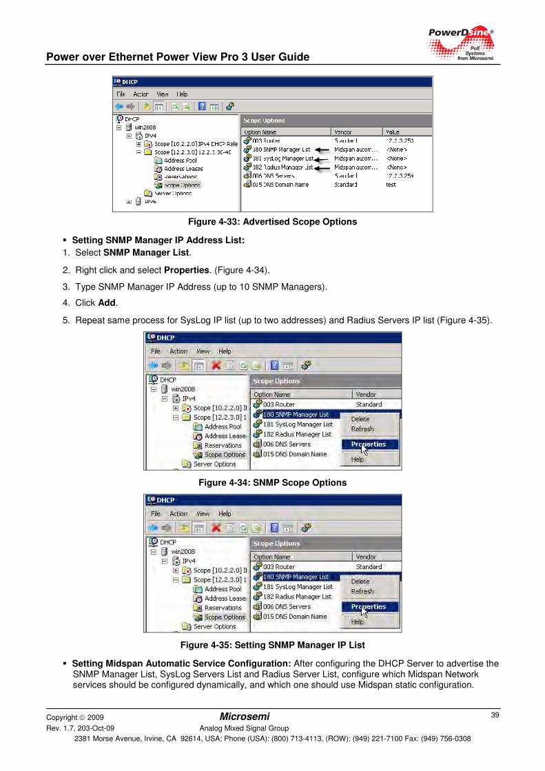
Power over Ethernet Power View Pro 3 User Guide
Copyright 2009 Microsemi Rev. 1.7, 203-Oct-09 Analog Mixed Signal Group
2381 Morse Avenue, Irvine, CA 92614, USA; Phone (USA): (800) 713-4113, (ROW): (949) 221-7100 Fax: (949) 756-0308
39
Figure 4-33: Advertised Scope Options
� Setting SNMP Manager IP Address List:
1. Select SNMP Manager List.
2. Right click and select Properties. (Figure 4-34).
3. Type SNMP Manager IP Address (up to 10 SNMP Managers).
4. Click Add.
5. Repeat same process for SysLog IP list (up to two addresses) and Radius Servers IP list (Figure 4-35).
Figure 4-34: SNMP Scope Options
Figure 4-35: Setting SNMP Manager IP List
� Setting Midspan Automatic Service Configuration: After configuring the DHCP Server to advertise the SNMP Manager List, SysLog Servers List and Radius Server List, configure which Midspan Network services should be configured dynamically, and which one should use Midspan static configuration.
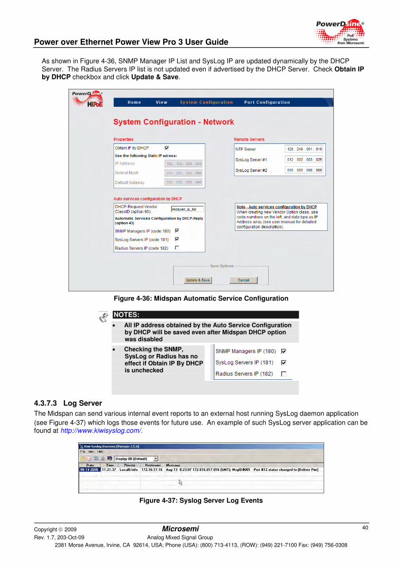
Power over Ethernet Power View Pro 3 User Guide
Copyright 2009 Microsemi Rev. 1.7, 203-Oct-09 Analog Mixed Signal Group
2381 Morse Avenue, Irvine, CA 92614, USA; Phone (USA): (800) 713-4113, (ROW): (949) 221-7100 Fax: (949) 756-0308
40
As shown in Figure 4-36, SNMP Manager IP List and SysLog IP are updated dynamically by the DHCP
Server. The Radius Servers IP list is not updated even if advertised by the DHCP Server. Check Obtain IP by DHCP checkbox and click Update & Save.
Figure 4-36: Midspan Automatic Service Configuration
NOTES:
• All IP address obtained by the Auto Service Configuration by DHCP will be saved even after Midspan DHCP option was disabled
• Checking the SNMP, SysLog or Radius has no effect if Obtain IP By DHCP is unchecked
4.3.7.3 Log Server
The Midspan can send various internal event reports to an external host running SysLog daemon application
(see Figure 4-37) which logs those events for future use. An example of such SysLog server application can be found at http://www.kiwisyslog.com/.
Figure 4-37: Syslog Server Log Events
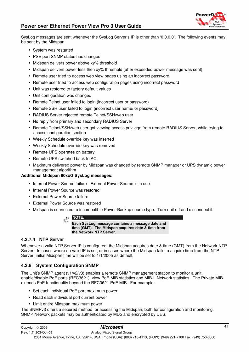
Power over Ethernet Power View Pro 3 User Guide
Copyright 2009 Microsemi Rev. 1.7, 203-Oct-09 Analog Mixed Signal Group
2381 Morse Avenue, Irvine, CA 92614, USA; Phone (USA): (800) 713-4113, (ROW): (949) 221-7100 Fax: (949) 756-0308
41
SysLog messages are sent whenever the SysLog Server’s IP is other than ‘0.0.0.0’. The following events may be sent by the Midspan:
� System was restarted
� PSE port SNMP status has changed
� Midspan delivers power above xy% threshold
� Midspan delivers power less then xy% threshold (after exceeded power message was sent)
� Remote user tried to access web view pages using an incorrect password
� Remote user tried to access web configuration pages using incorrect password
� Unit was restored to factory default values
� Unit configuration was changed
� Remote Telnet user failed to login (incorrect user or password)
� Remote SSH user failed to login (incorrect user name/ or password)
� RADIUS Server rejected remote Telnet/SSH/web user
� No reply from primary and secondary RADIUS Server
� Remote Telnet/SSH/web user got viewing access privilege from remote RADIUS Server, while trying to access configuration section
� Weekly Schedule override key was inserted
� Weekly Schedule override key was removed
� Remote UPS operates on battery
� Remote UPS switched back to AC
� Maximum delivered power by Midspan was changed by remote SNMP manager or UPS dynamic power management algorithm
Additional Midspan 90xxG SysLog messages:
� Internal Power Source failure. External Power Source is in use
� Internal Power Source was restored
� External Power Source failure
� External Power Source was restored
� Midspan is connected to incompatible Power-Backup source type. Turn unit off and disconnect it.
NOTE:
Each SysLog message contains a message date and time (GMT). The Midspan acquires date & time from the Network NTP Server.
4.3.7.4 NTP Server
Whenever a valid NTP Server IP is configured, the Midspan acquires date & time (GMT) from the Network NTP Server. In cases where no valid IP is set, or in cases where the Midspan fails to acquire time from the NTP Server, initial Midspan time will be set to 1/1/2005 as default.
4.3.8 System Configuration SNMP
The Unit’s SNMP agent (v1/v2/v3) enables a remote SNMP management station to monitor a unit, enable/disable PoE ports (RFC3621), view PoE MIB statistics and MIB-II Network statistics. The Private MIB extends PoE functionality beyond the RFC3621 PoE MIB. For example:
� Set each individual PoE port maximum power
� Read each individual port current power
� Limit entire Midspan maximum power
The SNMPv3 offers a secured method for accessing the Midspan, both for configuration and monitoring. SNMP Network packets may be authenticated by MD5 and encrypted by DES.
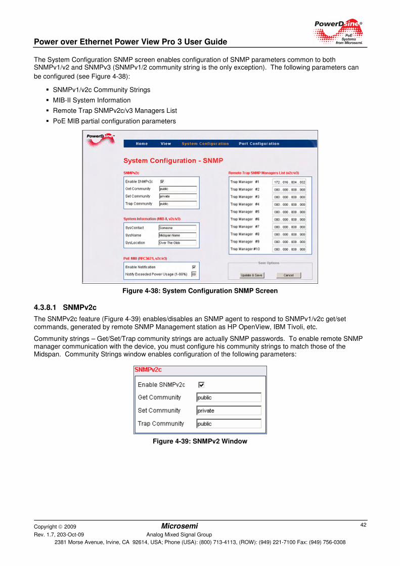
Power over Ethernet Power View Pro 3 User Guide
Copyright 2009 Microsemi Rev. 1.7, 203-Oct-09 Analog Mixed Signal Group
2381 Morse Avenue, Irvine, CA 92614, USA; Phone (USA): (800) 713-4113, (ROW): (949) 221-7100 Fax: (949) 756-0308
42
The System Configuration SNMP screen enables configuration of SNMP parameters common to both SNMPv1/v2 and SNMPv3 (SNMPv1/2 community string is the only exception). The following parameters can
be configured (see Figure 4-38):
� SNMPv1/v2c Community Strings
� MIB-II System Information
� Remote Trap SNMPv2c/v3 Managers List
� PoE MIB partial configuration parameters
Figure 4-38: System Configuration SNMP Screen
4.3.8.1 SNMPv2c
The SNMPv2c feature (Figure 4-39) enables/disables an SNMP agent to respond to SNMPv1/v2c get/set commands, generated by remote SNMP Management station as HP OpenView, IBM Tivoli, etc.
Community strings – Get/Set/Trap community strings are actually SNMP passwords. To enable remote SNMP manager communication with the device, you must configure his community strings to match those of the Midspan. Community Strings window enables configuration of the following parameters:
Figure 4-39: SNMPv2 Window
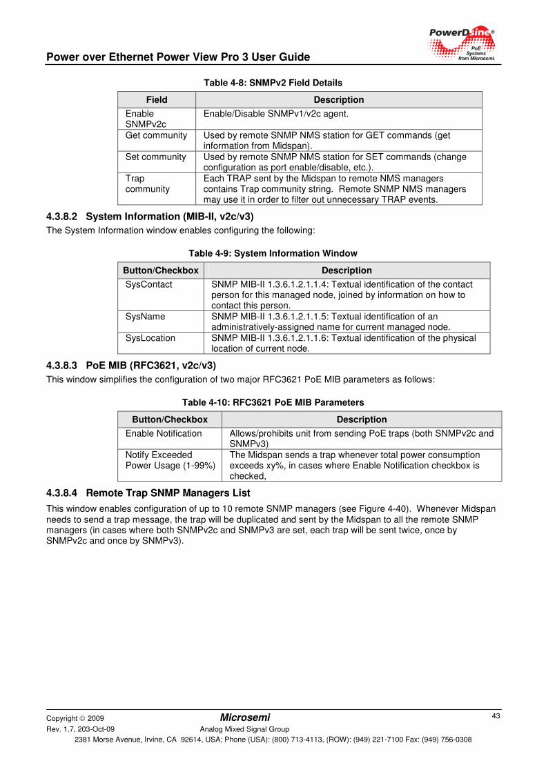
Power over Ethernet Power View Pro 3 User Guide
Copyright 2009 Microsemi Rev. 1.7, 203-Oct-09 Analog Mixed Signal Group
2381 Morse Avenue, Irvine, CA 92614, USA; Phone (USA): (800) 713-4113, (ROW): (949) 221-7100 Fax: (949) 756-0308
43
Table 4-8: SNMPv2 Field Details
Field Description
Enable SNMPv2c
Enable/Disable SNMPv1/v2c agent.
Get community Used by remote SNMP NMS station for GET commands (get information from Midspan).
Set community Used by remote SNMP NMS station for SET commands (change configuration as port enable/disable, etc.).
Trap community
Each TRAP sent by the Midspan to remote NMS managers contains Trap community string. Remote SNMP NMS managers may use it in order to filter out unnecessary TRAP events.
4.3.8.2 System Information (MIB-II, v2c/v3)
The System Information window enables configuring the following:
Table 4-9: System Information Window
Button/Checkbox Description
SysContact SNMP MIB-II 1.3.6.1.2.1.1.4: Textual identification of the contact person for this managed node, joined by information on how to contact this person.
SysName SNMP MIB-II 1.3.6.1.2.1.1.5: Textual identification of an administratively-assigned name for current managed node.
SysLocation SNMP MIB-II 1.3.6.1.2.1.1.6: Textual identification of the physical location of current node.
4.3.8.3 PoE MIB (RFC3621, v2c/v3)
This window simplifies the configuration of two major RFC3621 PoE MIB parameters as follows:
Table 4-10: RFC3621 PoE MIB Parameters
Button/Checkbox Description
Enable Notification Allows/prohibits unit from sending PoE traps (both SNMPv2c and SNMPv3)
Notify Exceeded Power Usage (1-99%)
The Midspan sends a trap whenever total power consumption exceeds xy%, in cases where Enable Notification checkbox is checked,
4.3.8.4 Remote Trap SNMP Managers List
This window enables configuration of up to 10 remote SNMP managers (see Figure 4-40). Whenever Midspan needs to send a trap message, the trap will be duplicated and sent by the Midspan to all the remote SNMP managers (in cases where both SNMPv2c and SNMPv3 are set, each trap will be sent twice, once by SNMPv2c and once by SNMPv3).
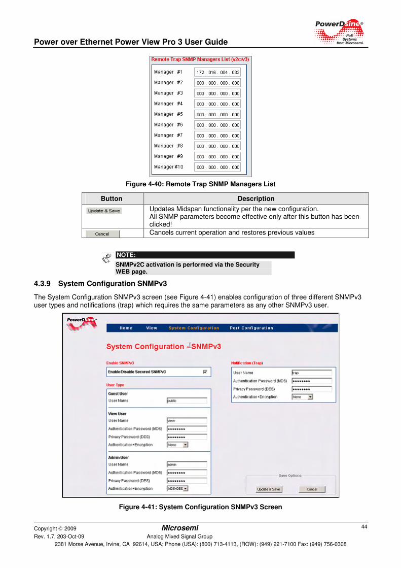
Power over Ethernet Power View Pro 3 User Guide
Copyright 2009 Microsemi Rev. 1.7, 203-Oct-09 Analog Mixed Signal Group
2381 Morse Avenue, Irvine, CA 92614, USA; Phone (USA): (800) 713-4113, (ROW): (949) 221-7100 Fax: (949) 756-0308
44
Figure 4-40: Remote Trap SNMP Managers List
Button Description
Updates Midspan functionality per the new configuration. All SNMP parameters become effective only after this button has been clicked!
Cancels current operation and restores previous values
NOTE:
SNMPv2C activation is performed via the Security WEB page.
4.3.9 System Configuration SNMPv3
The System Configuration SNMPv3 screen (see Figure 4-41) enables configuration of three different SNMPv3 user types and notifications (trap) which requires the same parameters as any other SNMPv3 user.
Figure 4-41: System Configuration SNMPv3 Screen
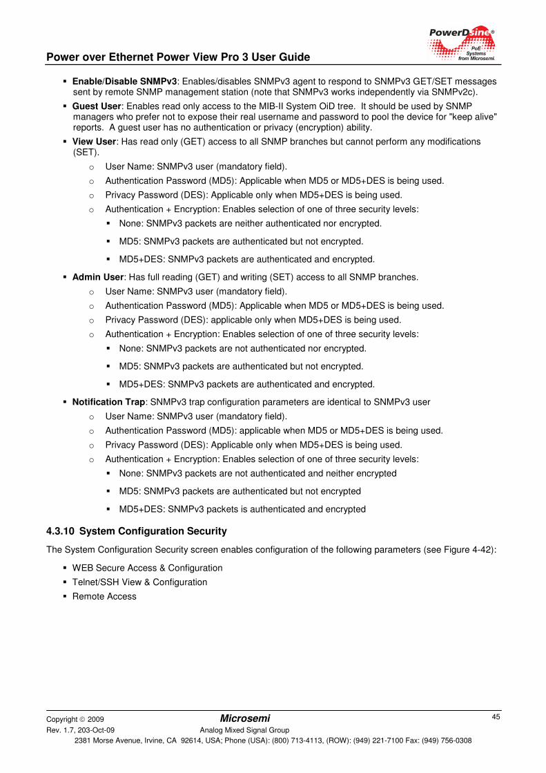
Power over Ethernet Power View Pro 3 User Guide
Copyright 2009 Microsemi Rev. 1.7, 203-Oct-09 Analog Mixed Signal Group
2381 Morse Avenue, Irvine, CA 92614, USA; Phone (USA): (800) 713-4113, (ROW): (949) 221-7100 Fax: (949) 756-0308
45
� Enable/Disable SNMPv3: Enables/disables SNMPv3 agent to respond to SNMPv3 GET/SET messages sent by remote SNMP management station (note that SNMPv3 works independently via SNMPv2c).
� Guest User: Enables read only access to the MIB-II System OiD tree. It should be used by SNMP managers who prefer not to expose their real username and password to pool the device for "keep alive" reports. A guest user has no authentication or privacy (encryption) ability.
� View User: Has read only (GET) access to all SNMP branches but cannot perform any modifications (SET).
o User Name: SNMPv3 user (mandatory field).
o Authentication Password (MD5): Applicable when MD5 or MD5+DES is being used.
o Privacy Password (DES): Applicable only when MD5+DES is being used.
o Authentication + Encryption: Enables selection of one of three security levels:
� None: SNMPv3 packets are neither authenticated nor encrypted.
� MD5: SNMPv3 packets are authenticated but not encrypted.
� MD5+DES: SNMPv3 packets are authenticated and encrypted.
� Admin User: Has full reading (GET) and writing (SET) access to all SNMP branches.
o User Name: SNMPv3 user (mandatory field).
o Authentication Password (MD5): Applicable when MD5 or MD5+DES is being used.
o Privacy Password (DES): applicable only when MD5+DES is being used.
o Authentication + Encryption: Enables selection of one of three security levels:
� None: SNMPv3 packets are not authenticated nor encrypted.
� MD5: SNMPv3 packets are authenticated but not encrypted.
� MD5+DES: SNMPv3 packets are authenticated and encrypted.
� Notification Trap: SNMPv3 trap configuration parameters are identical to SNMPv3 user
o User Name: SNMPv3 user (mandatory field).
o Authentication Password (MD5): applicable when MD5 or MD5+DES is being used.
o Privacy Password (DES): Applicable only when MD5+DES is being used.
o Authentication + Encryption: Enables selection of one of three security levels:
� None: SNMPv3 packets are not authenticated and neither encrypted
� MD5: SNMPv3 packets are authenticated but not encrypted
� MD5+DES: SNMPv3 packets is authenticated and encrypted
4.3.10 System Configuration Security
The System Configuration Security screen enables configuration of the following parameters (see Figure 4-42):
� WEB Secure Access & Configuration
� Telnet/SSH View & Configuration
� Remote Access

Power over Ethernet Power View Pro 3 User Guide
Copyright 2009 Microsemi Rev. 1.7, 203-Oct-09 Analog Mixed Signal Group
2381 Morse Avenue, Irvine, CA 92614, USA; Phone (USA): (800) 713-4113, (ROW): (949) 221-7100 Fax: (949) 756-0308
46
Figure 4-42: System Configuration Security Screen
4.3.10.1 Web Secure Access & Configuration
Web pages are divided into two sections, View and Configuration. View web pages provide status reports and configuration summaries, without being able to change configuration. Configuration web pages (under System Configuration and Port Configuration) enable the user to view and modify the Midspan configuration.
View web pages and Configuration web pages use different passwords. View user name and password provides access only to View web pages, while configuration user name and password provides access both to
View and Configuration Web pages (see Figure 4-43).
Figure 4-43: Web Secure Access & Configuration Window
NOTE:
Disabling Web View/Configuration password protection is applicable only when RADIUS Authentication is disabled!
4.3.10.2 Telnet/SSH View & Configuration
The Telnet/SSH remote terminal are always password protected.
The Telnet/SSH menu is divided into View privilege and Configuration privilege sub menus (see Figure 4-44).
� View privilege: Can view Telnet/SSH text menus but will be rejected when trying to access the Configuration text menus.
� Configuration privilege: can access both to View and Configuration text menus.
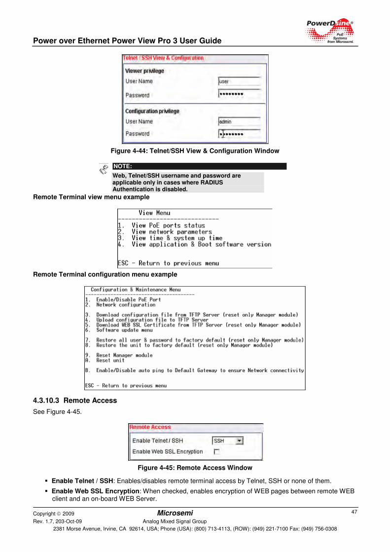
Power over Ethernet Power View Pro 3 User Guide
Copyright 2009 Microsemi Rev. 1.7, 203-Oct-09 Analog Mixed Signal Group
2381 Morse Avenue, Irvine, CA 92614, USA; Phone (USA): (800) 713-4113, (ROW): (949) 221-7100 Fax: (949) 756-0308
47
Figure 4-44: Telnet/SSH View & Configuration Window
NOTE:
Web, Telnet/SSH username and password are applicable only in cases where RADIUS Authentication is disabled.
Remote Terminal view menu example
Remote Terminal configuration menu example
4.3.10.3 Remote Access
See Figure 4-45.
Figure 4-45: Remote Access Window
� Enable Telnet / SSH: Enables/disables remote terminal access by Telnet, SSH or none of them.
� Enable Web SSL Encryption: When checked, enables encryption of WEB pages between remote WEB client and an on-board WEB Server.
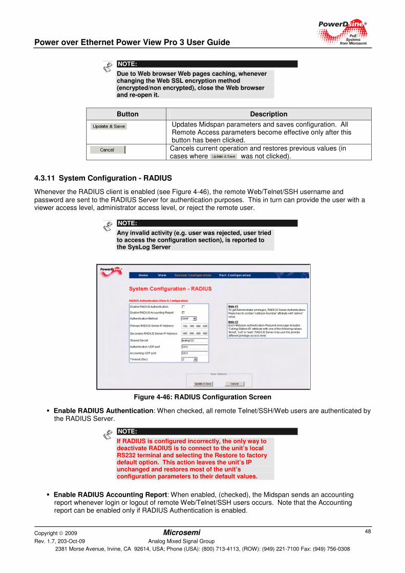
Power over Ethernet Power View Pro 3 User Guide
Copyright 2009 Microsemi Rev. 1.7, 203-Oct-09 Analog Mixed Signal Group
2381 Morse Avenue, Irvine, CA 92614, USA; Phone (USA): (800) 713-4113, (ROW): (949) 221-7100 Fax: (949) 756-0308
48
NOTE:
Due to Web browser Web pages caching, whenever changing the Web SSL encryption method (encrypted/non encrypted), close the Web browser and re-open it.
Button Description
Updates Midspan parameters and saves configuration. All Remote Access parameters become effective only after this button has been clicked.
Cancels current operation and restores previous values (in cases where was not clicked).
4.3.11 System Configuration - RADIUS
Whenever the RADIUS client is enabled (see Figure 4-46), the remote Web/Telnet/SSH username and password are sent to the RADIUS Server for authentication purposes. This in turn can provide the user with a viewer access level, administrator access level, or reject the remote user.
NOTE:
Any invalid activity (e.g. user was rejected, user tried to access the configuration section), is reported to the SysLog Server
Figure 4-46: RADIUS Configuration Screen
� Enable RADIUS Authentication: When checked, all remote Telnet/SSH/Web users are authenticated by the RADIUS Server.
NOTE:
If RADIUS is configured incorrectly, the only way to deactivate RADIUS is to connect to the unit’s local RS232 terminal and selecting the Restore to factory default option. This action leaves the unit’s IP unchanged and restores most of the unit’s configuration parameters to their default values.
� Enable RADIUS Accounting Report: When enabled, (checked), the Midspan sends an accounting report whenever login or logout of remote Web/Telnet/SSH users occurs. Note that the Accounting report can be enabled only if RADIUS Authentication is enabled.
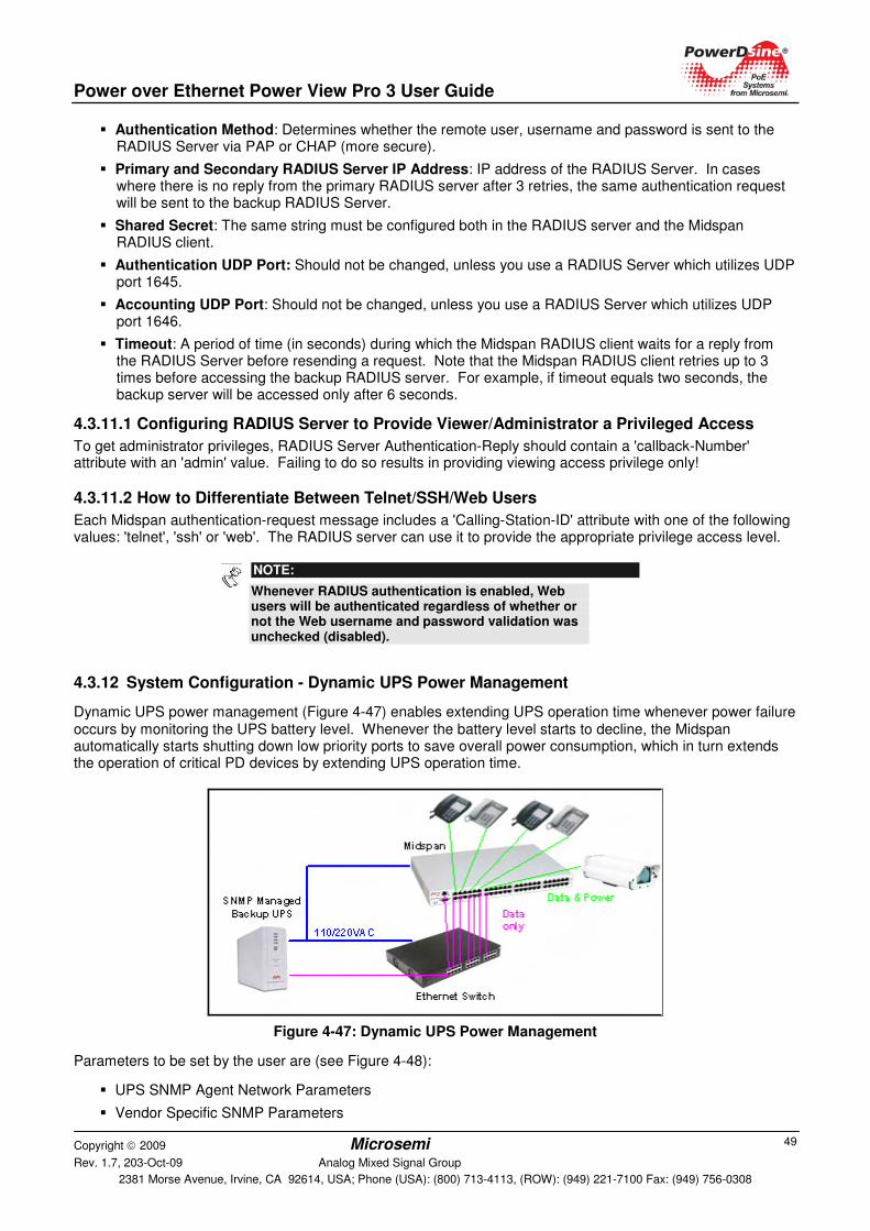
Power over Ethernet Power View Pro 3 User Guide
Copyright 2009 Microsemi Rev. 1.7, 203-Oct-09 Analog Mixed Signal Group
2381 Morse Avenue, Irvine, CA 92614, USA; Phone (USA): (800) 713-4113, (ROW): (949) 221-7100 Fax: (949) 756-0308
49
� Authentication Method: Determines whether the remote user, username and password is sent to the RADIUS Server via PAP or CHAP (more secure).
� Primary and Secondary RADIUS Server IP Address: IP address of the RADIUS Server. In cases where there is no reply from the primary RADIUS server after 3 retries, the same authentication request will be sent to the backup RADIUS Server.
� Shared Secret: The same string must be configured both in the RADIUS server and the Midspan RADIUS client.
� Authentication UDP Port: Should not be changed, unless you use a RADIUS Server which utilizes UDP port 1645.
� Accounting UDP Port: Should not be changed, unless you use a RADIUS Server which utilizes UDP port 1646.
� Timeout: A period of time (in seconds) during which the Midspan RADIUS client waits for a reply from the RADIUS Server before resending a request. Note that the Midspan RADIUS client retries up to 3 times before accessing the backup RADIUS server. For example, if timeout equals two seconds, the backup server will be accessed only after 6 seconds.
4.3.11.1 Configuring RADIUS Server to Provide Viewer/Administrator a Privileged Access
To get administrator privileges, RADIUS Server Authentication-Reply should contain a 'callback-Number' attribute with an 'admin' value. Failing to do so results in providing viewing access privilege only!
4.3.11.2 How to Differentiate Between Telnet/SSH/Web Users
Each Midspan authentication-request message includes a 'Calling-Station-ID' attribute with one of the following values: 'telnet', 'ssh' or 'web'. The RADIUS server can use it to provide the appropriate privilege access level.
NOTE:
Whenever RADIUS authentication is enabled, Web users will be authenticated regardless of whether or not the Web username and password validation was unchecked (disabled).
4.3.12 System Configuration - Dynamic UPS Power Management
Dynamic UPS power management (Figure 4-47) enables extending UPS operation time whenever power failure occurs by monitoring the UPS battery level. Whenever the battery level starts to decline, the Midspan automatically starts shutting down low priority ports to save overall power consumption, which in turn extends the operation of critical PD devices by extending UPS operation time.
Figure 4-47: Dynamic UPS Power Management
Parameters to be set by the user are (see Figure 4-48):
� UPS SNMP Agent Network Parameters
� Vendor Specific SNMP Parameters
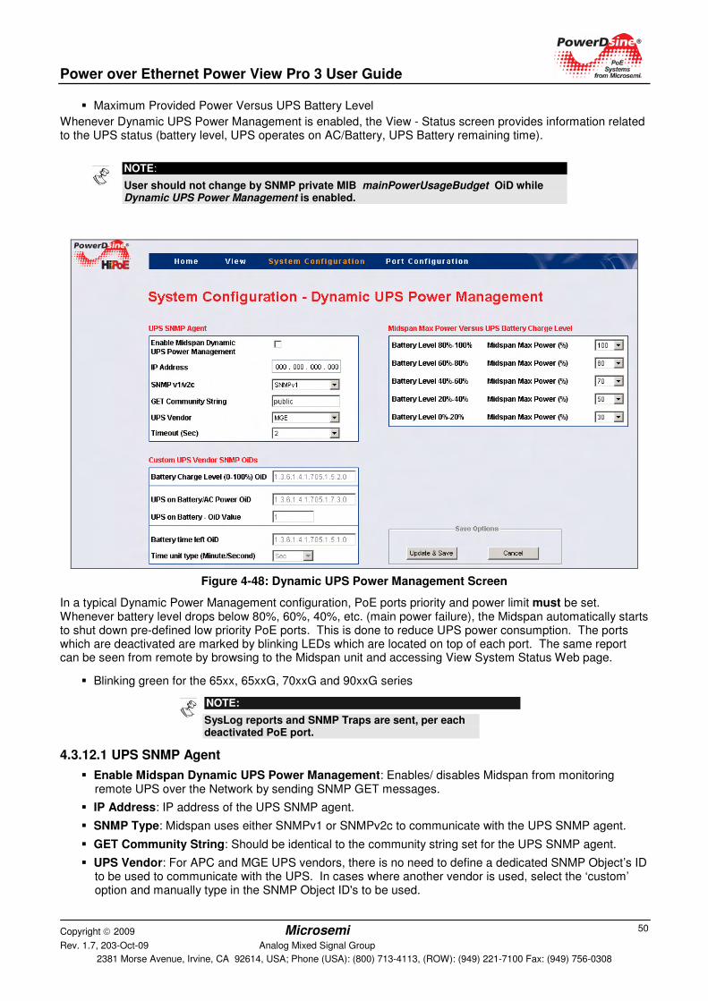
Power over Ethernet Power View Pro 3 User Guide
Copyright 2009 Microsemi Rev. 1.7, 203-Oct-09 Analog Mixed Signal Group
2381 Morse Avenue, Irvine, CA 92614, USA; Phone (USA): (800) 713-4113, (ROW): (949) 221-7100 Fax: (949) 756-0308
50
� Maximum Provided Power Versus UPS Battery Level
Whenever Dynamic UPS Power Management is enabled, the View - Status screen provides information related to the UPS status (battery level, UPS operates on AC/Battery, UPS Battery remaining time).
Figure 4-48: Dynamic UPS Power Management Screen
In a typical Dynamic Power Management configuration, PoE ports priority and power limit must be set. Whenever battery level drops below 80%, 60%, 40%, etc. (main power failure), the Midspan automatically starts to shut down pre-defined low priority PoE ports. This is done to reduce UPS power consumption. The ports which are deactivated are marked by blinking LEDs which are located on top of each port. The same report can be seen from remote by browsing to the Midspan unit and accessing View System Status Web page.
� Blinking green for the 65xx, 65xxG, 70xxG and 90xxG series
NOTE:
SysLog reports and SNMP Traps are sent, per each deactivated PoE port.
4.3.12.1 UPS SNMP Agent
� Enable Midspan Dynamic UPS Power Management: Enables/ disables Midspan from monitoring remote UPS over the Network by sending SNMP GET messages.
� IP Address: IP address of the UPS SNMP agent.
� SNMP Type: Midspan uses either SNMPv1 or SNMPv2c to communicate with the UPS SNMP agent.
� GET Community String: Should be identical to the community string set for the UPS SNMP agent.
� UPS Vendor: For APC and MGE UPS vendors, there is no need to define a dedicated SNMP Object’s ID to be used to communicate with the UPS. In cases where another vendor is used, select the ‘custom’ option and manually type in the SNMP Object ID's to be used.
NOTE:
User should not change by SNMP private MIB mainPowerUsageBudget OiD while Dynamic UPS Power Management is enabled.
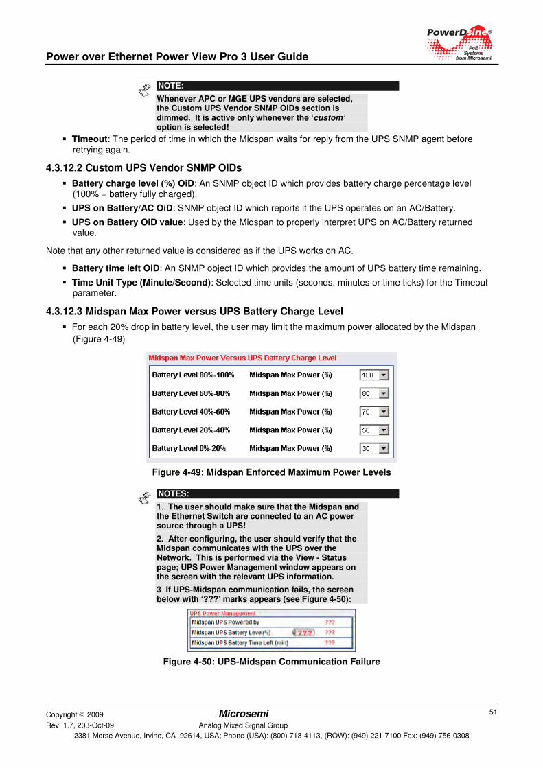
Power over Ethernet Power View Pro 3 User Guide
Copyright 2009 Microsemi Rev. 1.7, 203-Oct-09 Analog Mixed Signal Group
2381 Morse Avenue, Irvine, CA 92614, USA; Phone (USA): (800) 713-4113, (ROW): (949) 221-7100 Fax: (949) 756-0308
51
NOTE:
Whenever APC or MGE UPS vendors are selected, the Custom UPS Vendor SNMP OiDs section is dimmed. It is active only whenever the ‘custom’ option is selected!
� Timeout: The period of time in which the Midspan waits for reply from the UPS SNMP agent before retrying again.
4.3.12.2 Custom UPS Vendor SNMP OIDs
� Battery charge level (%) OiD: An SNMP object ID which provides battery charge percentage level (100% = battery fully charged).
� UPS on Battery/AC OiD: SNMP object ID which reports if the UPS operates on an AC/Battery.
� UPS on Battery OiD value: Used by the Midspan to properly interpret UPS on AC/Battery returned value.
Note that any other returned value is considered as if the UPS works on AC.
� Battery time left OiD: An SNMP object ID which provides the amount of UPS battery time remaining.
� Time Unit Type (Minute/Second): Selected time units (seconds, minutes or time ticks) for the Timeout parameter.
4.3.12.3 Midspan Max Power versus UPS Battery Charge Level
� For each 20% drop in battery level, the user may limit the maximum power allocated by the Midspan
(Figure 4-49)
Figure 4-49: Midspan Enforced Maximum Power Levels
NOTES:
1. The user should make sure that the Midspan and the Ethernet Switch are connected to an AC power source through a UPS!
2. After configuring, the user should verify that the Midspan communicates with the UPS over the Network. This is performed via the View - Status page; UPS Power Management window appears on the screen with the relevant UPS information.
3 If UPS-Midspan communication fails, the screen below with ‘???’ marks appears (see Figure 4-50):
Figure 4-50: UPS-Midspan Communication Failure
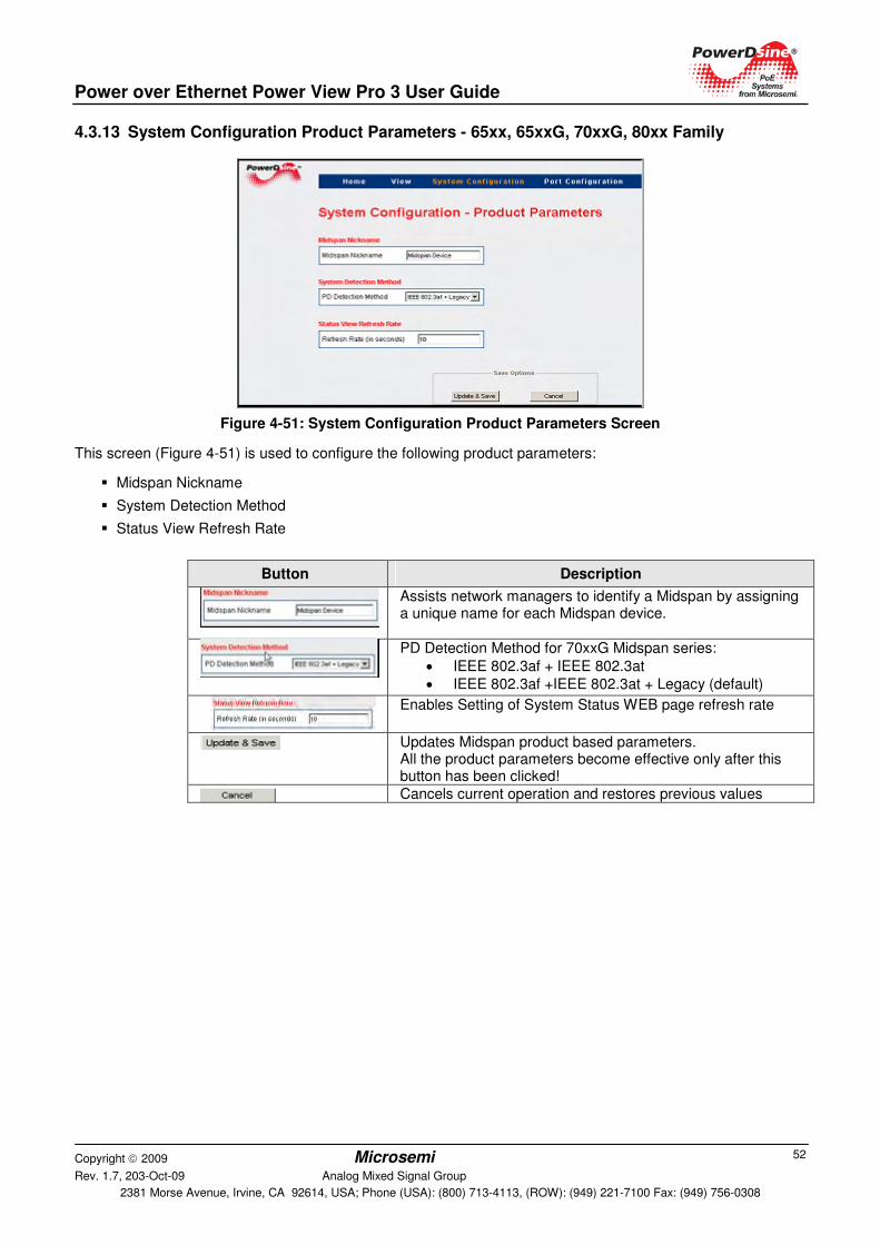
Power over Ethernet Power View Pro 3 User Guide
Copyright 2009 Microsemi Rev. 1.7, 203-Oct-09 Analog Mixed Signal Group
2381 Morse Avenue, Irvine, CA 92614, USA; Phone (USA): (800) 713-4113, (ROW): (949) 221-7100 Fax: (949) 756-0308
52
4.3.13 System Configuration Product Parameters - 65xx, 65xxG, 70xxG, 80xx Family
Figure 4-51: System Configuration Product Parameters Screen
This screen (Figure 4-51) is used to configure the following product parameters:
� Midspan Nickname
� System Detection Method
� Status View Refresh Rate
Button Description
Assists network managers to identify a Midspan by assigning a unique name for each Midspan device.
PD Detection Method for 70xxG Midspan series:
• IEEE 802.3af + IEEE 802.3at
• IEEE 802.3af +IEEE 802.3at + Legacy (default)
Enables Setting of System Status WEB page refresh rate
Updates Midspan product based parameters. All the product parameters become effective only after this button has been clicked!
Cancels current operation and restores previous values
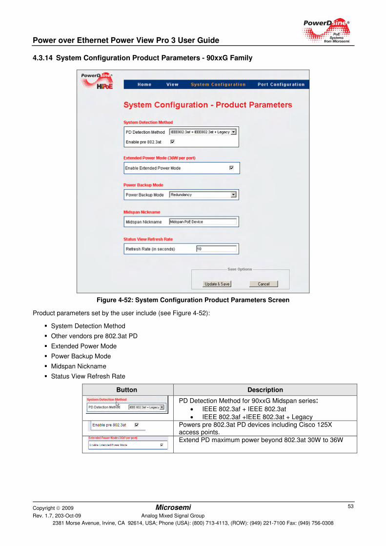
Power over Ethernet Power View Pro 3 User Guide
Copyright 2009 Microsemi Rev. 1.7, 203-Oct-09 Analog Mixed Signal Group
2381 Morse Avenue, Irvine, CA 92614, USA; Phone (USA): (800) 713-4113, (ROW): (949) 221-7100 Fax: (949) 756-0308
53
4.3.14 System Configuration Product Parameters - 90xxG Family
Figure 4-52: System Configuration Product Parameters Screen
Product parameters set by the user include (see Figure 4-52):
� System Detection Method
� Other vendors pre 802.3at PD
� Extended Power Mode
� Power Backup Mode
� Midspan Nickname
� Status View Refresh Rate
Button Description
PD Detection Method for 90xxG Midspan series:
• IEEE 802.3af + IEEE 802.3at
• IEEE 802.3af +IEEE 802.3at + Legacy
Powers pre 802.3at PD devices including Cisco 125X access points.
Extend PD maximum power beyond 802.3at 30W to 36W
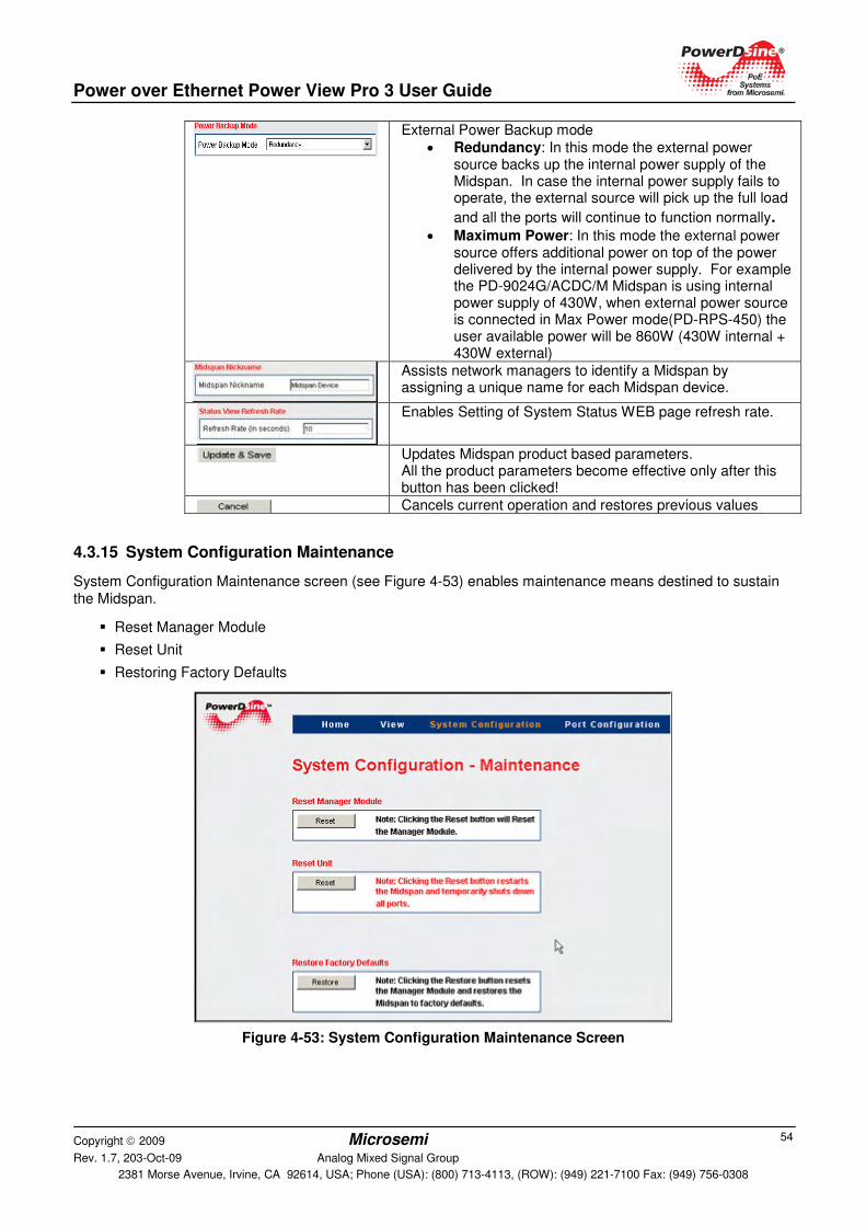
Power over Ethernet Power View Pro 3 User Guide
Copyright 2009 Microsemi Rev. 1.7, 203-Oct-09 Analog Mixed Signal Group
2381 Morse Avenue, Irvine, CA 92614, USA; Phone (USA): (800) 713-4113, (ROW): (949) 221-7100 Fax: (949) 756-0308
54
External Power Backup mode
• Redundancy: In this mode the external power source backs up the internal power supply of the Midspan. In case the internal power supply fails to operate, the external source will pick up the full load
and all the ports will continue to function normally.
• Maximum Power: In this mode the external power source offers additional power on top of the power delivered by the internal power supply. For example the PD-9024G/ACDC/M Midspan is using internal power supply of 430W, when external power source is connected in Max Power mode(PD-RPS-450) the user available power will be 860W (430W internal + 430W external)
Assists network managers to identify a Midspan by assigning a unique name for each Midspan device.
Enables Setting of System Status WEB page refresh rate.
Updates Midspan product based parameters. All the product parameters become effective only after this button has been clicked!
Cancels current operation and restores previous values
4.3.15 System Configuration Maintenance
System Configuration Maintenance screen (see Figure 4-53) enables maintenance means destined to sustain the Midspan.
� Reset Manager Module
� Reset Unit
� Restoring Factory Defaults
Figure 4-53: System Configuration Maintenance Screen
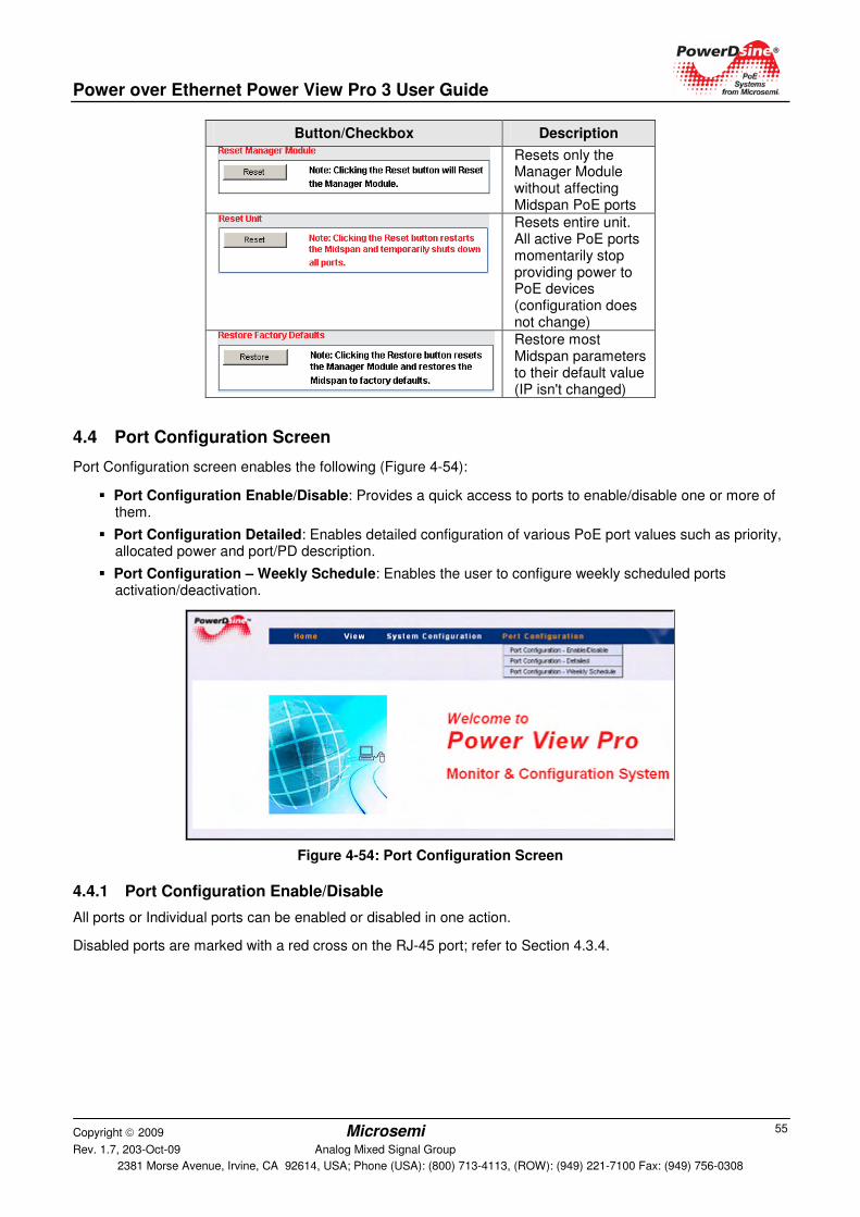
Power over Ethernet Power View Pro 3 User Guide
Copyright 2009 Microsemi Rev. 1.7, 203-Oct-09 Analog Mixed Signal Group
2381 Morse Avenue, Irvine, CA 92614, USA; Phone (USA): (800) 713-4113, (ROW): (949) 221-7100 Fax: (949) 756-0308
55
Button/Checkbox Description
Resets only the Manager Module without affecting Midspan PoE ports
Resets entire unit. All active PoE ports momentarily stop providing power to PoE devices (configuration does not change)
Restore most Midspan parameters to their default value (IP isn't changed)
4.4 Port Configuration Screen
Port Configuration screen enables the following (Figure 4-54):
� Port Configuration Enable/Disable: Provides a quick access to ports to enable/disable one or more of them.
� Port Configuration Detailed: Enables detailed configuration of various PoE port values such as priority, allocated power and port/PD description.
� Port Configuration – Weekly Schedule: Enables the user to configure weekly scheduled ports activation/deactivation.
Figure 4-54: Port Configuration Screen
4.4.1 Port Configuration Enable/Disable
All ports or Individual ports can be enabled or disabled in one action.
Disabled ports are marked with a red cross on the RJ-45 port; refer to Section 4.3.4.
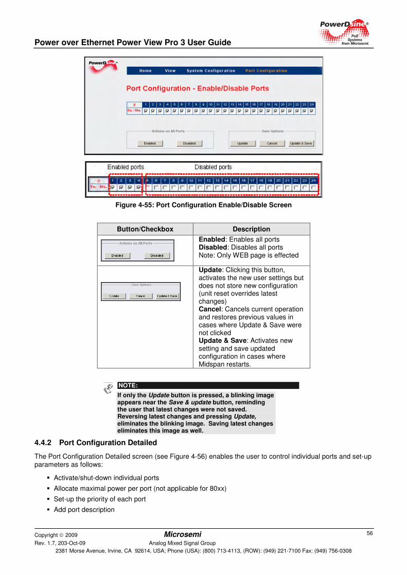
Power over Ethernet Power View Pro 3 User Guide
Copyright 2009 Microsemi Rev. 1.7, 203-Oct-09 Analog Mixed Signal Group
2381 Morse Avenue, Irvine, CA 92614, USA; Phone (USA): (800) 713-4113, (ROW): (949) 221-7100 Fax: (949) 756-0308
56
Figure 4-55: Port Configuration Enable/Disable Screen
Button/Checkbox Description
Enabled: Enables all ports Disabled: Disables all ports Note: Only WEB page is effected
Update: Clicking this button, activates the new user settings but does not store new configuration (unit reset overrides latest changes) Cancel: Cancels current operation and restores previous values in cases where Update & Save were not clicked Update & Save: Activates new setting and save updated configuration in cases where Midspan restarts.
NOTE:
If only the Update button is pressed, a blinking image appears near the Save & update button, reminding the user that latest changes were not saved. Reversing latest changes and pressing Update, eliminates the blinking image. Saving latest changes eliminates this image as well.
4.4.2 Port Configuration Detailed
The Port Configuration Detailed screen (see Figure 4-56) enables the user to control individual ports and set-up parameters as follows:
� Activate/shut-down individual ports
� Allocate maximal power per port (not applicable for 80xx)
� Set-up the priority of each port
� Add port description
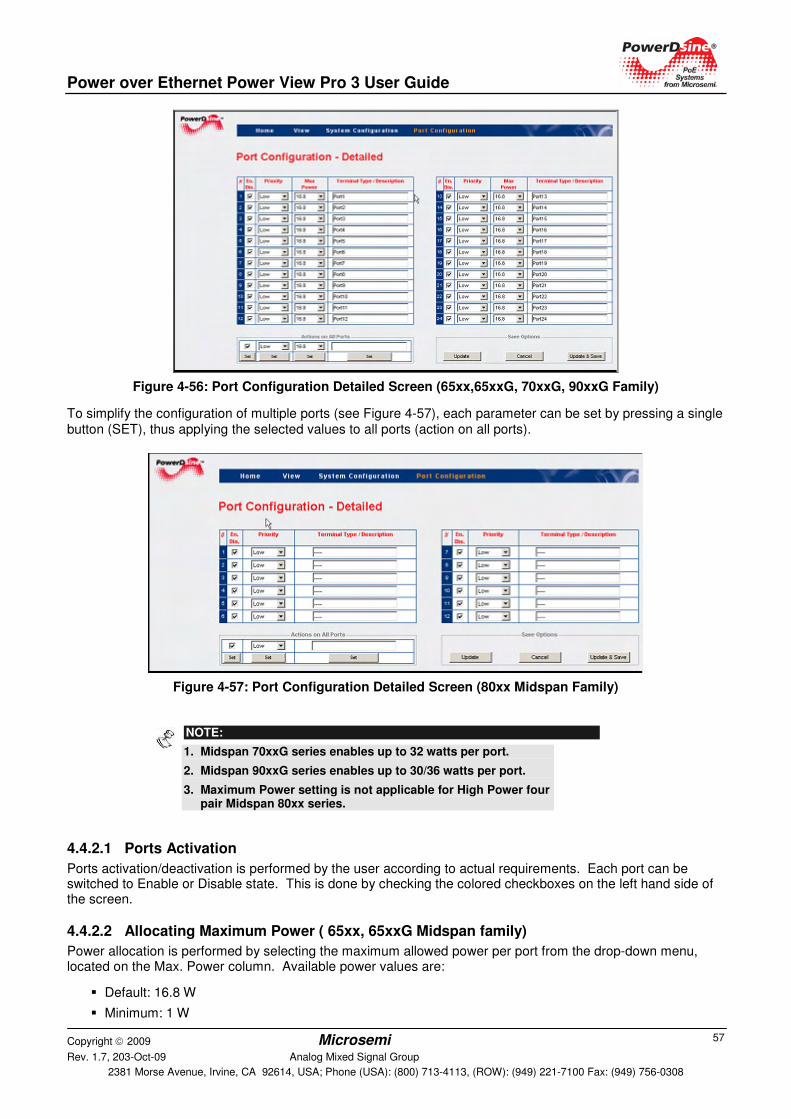
Power over Ethernet Power View Pro 3 User Guide
Copyright 2009 Microsemi Rev. 1.7, 203-Oct-09 Analog Mixed Signal Group
2381 Morse Avenue, Irvine, CA 92614, USA; Phone (USA): (800) 713-4113, (ROW): (949) 221-7100 Fax: (949) 756-0308
57
Figure 4-56: Port Configuration Detailed Screen (65xx,65xxG, 70xxG, 90xxG Family)
To simplify the configuration of multiple ports (see Figure 4-57), each parameter can be set by pressing a single button (SET), thus applying the selected values to all ports (action on all ports).
Figure 4-57: Port Configuration Detailed Screen (80xx Midspan Family)
4.4.2.1 Ports Activation
Ports activation/deactivation is performed by the user according to actual requirements. Each port can be switched to Enable or Disable state. This is done by checking the colored checkboxes on the left hand side of the screen.
4.4.2.2 Allocating Maximum Power ( 65xx, 65xxG Midspan family)
Power allocation is performed by selecting the maximum allowed power per port from the drop-down menu, located on the Max. Power column. Available power values are:
� Default: 16.8 W
� Minimum: 1 W
NOTE:
1. Midspan 70xxG series enables up to 32 watts per port.
2. Midspan 90xxG series enables up to 30/36 watts per port.
3. Maximum Power setting is not applicable for High Power four pair Midspan 80xx series.
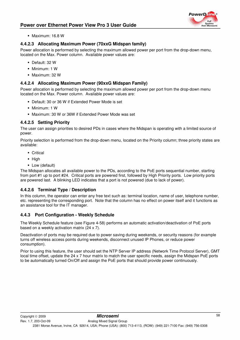
Power over Ethernet Power View Pro 3 User Guide
Copyright 2009 Microsemi Rev. 1.7, 203-Oct-09 Analog Mixed Signal Group
2381 Morse Avenue, Irvine, CA 92614, USA; Phone (USA): (800) 713-4113, (ROW): (949) 221-7100 Fax: (949) 756-0308
58
� Maximum: 16.8 W
4.4.2.3 Allocating Maximum Power (70xxG Midspan family)
Power allocation is performed by selecting the maximum allowed power per port from the drop-down menu, located on the Max. Power column. Available power values are:
� Default: 32 W
� Minimum: 1 W
� Maximum: 32 W
4.4.2.4 Allocating Maximum Power (90xxG Midspan Family)
Power allocation is performed by selecting the maximum allowed power per port from the drop-down menu located on the Max. Power column. Available power values are:
� Default: 30 or 36 W if Extended Power Mode is set
� Minimum: 1 W
� Maximum: 30 W or 36W if Extended Power Mode was set
4.4.2.5 Setting Priority
The user can assign priorities to desired PDs in cases where the Midspan is operating with a limited source of power.
Priority selection is performed from the drop-down menu, located on the Priority column; three priority states are available:
� Critical
� High
� Low (default)
The Midspan allocates all available power to the PDs, according to the PoE ports sequential number, starting from port #1 up to port #24. Critical ports are powered first, followed by High Priority ports. Low priority ports are powered last. A blinking LED indicates that a port is not powered (due to lack of power).
4.4.2.6 Terminal Type / Description
In this column, the operator can enter any free text such as: terminal location, name of user, telephone number, etc. representing the corresponding port. Note that the column has no effect on power itself and it functions as an assistance tool for the IT manager.
4.4.3 Port Configuration - Weekly Schedule
The Weekly Schedule feature (see Figure 4-58) performs an automatic activation/deactivation of PoE ports based on a weekly activation matrix (24 x 7).
Deactivation of ports may be required due to power saving during weekends, or security reasons (for example turns off wireless access points during weekends, disconnect unused IP Phones, or reduce power consumption).
Prior to using this feature, the user should set the NTP Server IP address (Network Time Protocol Server), GMT local time offset, update the 24 x 7 hour matrix to match the user specific needs, assign the Midspan PoE ports to be automatically turned On/Off and assign the PoE ports that should provide power continuously.
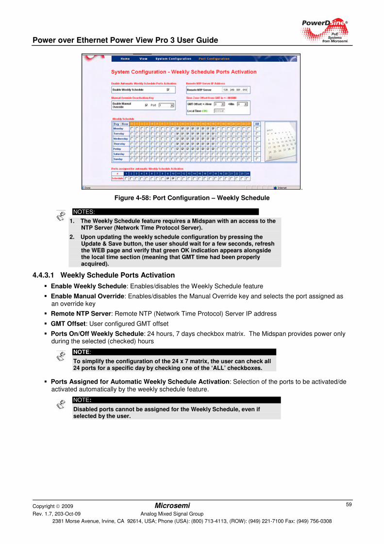
Power over Ethernet Power View Pro 3 User Guide
Copyright 2009 Microsemi Rev. 1.7, 203-Oct-09 Analog Mixed Signal Group
2381 Morse Avenue, Irvine, CA 92614, USA; Phone (USA): (800) 713-4113, (ROW): (949) 221-7100 Fax: (949) 756-0308
59
.
Figure 4-58: Port Configuration – Weekly Schedule
NOTES:
1. The Weekly Schedule feature requires a Midspan with an access to the NTP Server (Network Time Protocol Server).
2. Upon updating the weekly schedule configuration by pressing the Update & Save button, the user should wait for a few seconds, refresh the WEB page and verify that green OK indication appears alongside the local time section (meaning that GMT time had been properly acquired).
4.4.3.1 Weekly Schedule Ports Activation
� Enable Weekly Schedule: Enables/disables the Weekly Schedule feature
� Enable Manual Override: Enables/disables the Manual Override key and selects the port assigned as an override key
� Remote NTP Server: Remote NTP (Network Time Protocol) Server IP address
� GMT Offset: User configured GMT offset
� Ports On/Off Weekly Schedule: 24 hours, 7 days checkbox matrix. The Midspan provides power only during the selected (checked) hours
NOTE:
To simplify the configuration of the 24 x 7 matrix, the user can check all 24 ports for a specific day by checking one of the ‘ALL’ checkboxes.
� Ports Assigned for Automatic Weekly Schedule Activation: Selection of the ports to be activated/de activated automatically by the weekly schedule feature.
NOTE:
Disabled ports cannot be assigned for the Weekly Schedule, even if selected by the user.
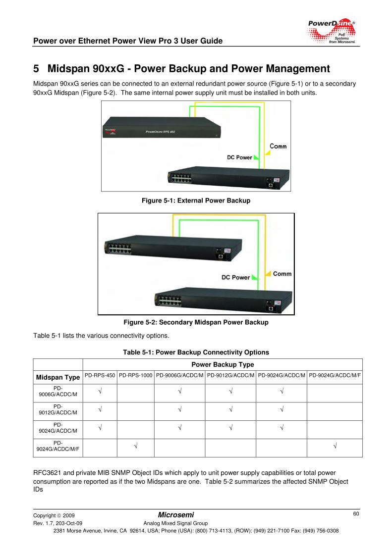
Power over Ethernet Power View Pro 3 User Guide
Copyright 2009 Microsemi Rev. 1.7, 203-Oct-09 Analog Mixed Signal Group
2381 Morse Avenue, Irvine, CA 92614, USA; Phone (USA): (800) 713-4113, (ROW): (949) 221-7100 Fax: (949) 756-0308
60
5 Midspan 90xxG - Power Backup and Power Management
Midspan 90xxG series can be connected to an external redundant power source (Figure 5-1) or to a secondary
90xxG Midspan (Figure 5-2). The same internal power supply unit must be installed in both units.
Figure 5-1: External Power Backup
Figure 5-2: Secondary Midspan Power Backup
Table 5-1 lists the various connectivity options.
Table 5-1: Power Backup Connectivity Options
Power Backup Type
Midspan Type PD-RPS-450 PD-RPS-1000 PD-9006G/ACDC/M PD-9012G/ACDC/M PD-9024G/ACDC/M PD-9024G/ACDC/M/F
PD-9006G/ACDC/M
√ √ √ √
PD-9012G/ACDC/M
√ √ √ √
PD-9024G/ACDC/M
√ √ √ √
PD-9024G/ACDC/M/F
√ √
RFC3621 and private MIB SNMP Object IDs which apply to unit power supply capabilities or total power
consumption are reported as if the two Midspans are one. Table 5-2 summarizes the affected SNMP Object IDs
Power over Ethernet Power View Pro 3 User Guide
Copyright 2009 Microsemi Rev. 1.7, 203-Oct-09 Analog Mixed Signal Group
2381 Morse Avenue, Irvine, CA 92614, USA; Phone (USA): (800) 713-4113, (ROW): (949) 221-7100 Fax: (949) 756-0308
61
Table 5-2: SNMP Object IDs Affected by 90xxG Midspan Power Backup Mode Connection
SNMP Object ID Power Backup Mode
pethMainPsePower (RFC3621) 430W/950W (Power backup mode = Redundant) 860W/1900W (Power backup mode = Maximum Power)
pethMainPseOperStatus (RFC3621)
Fault in case of power failure (Midspan is powered by RPS or 2nd Midspan)
pethMainPseConsumptionPower (RFC3621)
Total power consumption of both Midspans
pethMainPseUsageThreshold (RFC3621)
Sends a trap whenever both Midspan power consumption exceeds xy% out of pethMainPsePower OiD (total available power by both Midspans) power
mainPowerUsageBudget (private MIB) Changing power usage budget (%) in one Midspan will change it in the 2nd Midspan as well
mainPSE_MaxPower (private MIB) Total maximum power of both Midspans after it was reduced by pethMainPseUsageThreshold (%)
5.1 Viewing the Power Source Status
View the external power source status (Ok/Fail) and power source type (RPS/Midspan) in the View-Status Web
page (Figure 5-3). Refer to Section 4.3 for details on View - Status Screen.
Figure 5-3: Power Source Status
5.2 RPS Power Backup
Connecting a Midspan 90xxG to a redundant power source (RPS) provides power backup by enabling the Midspan to be powered by the unit's internal power source and the RPS power source. Two power backup modes are available:
� Redundancy: Maximum power that Midspan can provide remains the same as if no RPS is being used (430 W or 950 W). This mode guarantees that all active PoE ports continue to deliver same power regardless if Midspan is powered by its internal power source or by RPS.
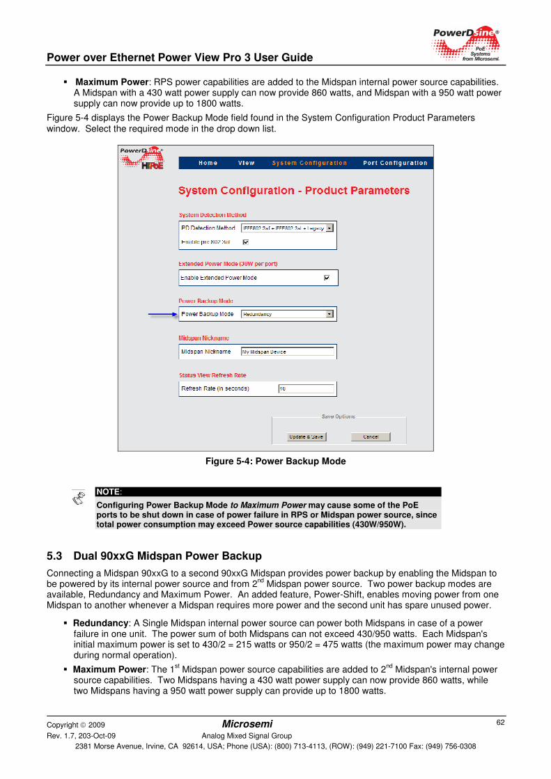
Power over Ethernet Power View Pro 3 User Guide
Copyright 2009 Microsemi Rev. 1.7, 203-Oct-09 Analog Mixed Signal Group
2381 Morse Avenue, Irvine, CA 92614, USA; Phone (USA): (800) 713-4113, (ROW): (949) 221-7100 Fax: (949) 756-0308
62
� Maximum Power: RPS power capabilities are added to the Midspan internal power source capabilities. A Midspan with a 430 watt power supply can now provide 860 watts, and Midspan with a 950 watt power supply can now provide up to 1800 watts.
Figure 5-4 displays the Power Backup Mode field found in the System Configuration Product Parameters window. Select the required mode in the drop down list.
Figure 5-4: Power Backup Mode
5.3 Dual 90xxG Midspan Power Backup
Connecting a Midspan 90xxG to a second 90xxG Midspan provides power backup by enabling the Midspan to be powered by its internal power source and from 2
nd Midspan power source. Two power backup modes are
available, Redundancy and Maximum Power. An added feature, Power-Shift, enables moving power from one Midspan to another whenever a Midspan requires more power and the second unit has spare unused power.
� Redundancy: A Single Midspan internal power source can power both Midspans in case of a power failure in one unit. The power sum of both Midspans can not exceed 430/950 watts. Each Midspan's initial maximum power is set to 430/2 = 215 watts or 950/2 = 475 watts (the maximum power may change during normal operation).
� Maximum Power: The 1st Midspan power source capabilities are added to 2
nd Midspan's internal power
source capabilities. Two Midspans having a 430 watt power supply can now provide 860 watts, while two Midspans having a 950 watt power supply can provide up to 1800 watts.
NOTE:
Configuring Power Backup Mode to Maximum Power may cause some of the PoE ports to be shut down in case of power failure in RPS or Midspan power source, since total power consumption may exceed Power source capabilities (430W/950W).
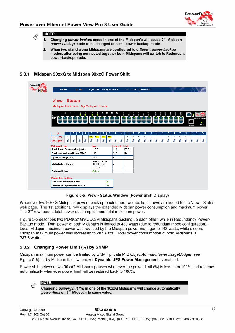
Power over Ethernet Power View Pro 3 User Guide
Copyright 2009 Microsemi Rev. 1.7, 203-Oct-09 Analog Mixed Signal Group
2381 Morse Avenue, Irvine, CA 92614, USA; Phone (USA): (800) 713-4113, (ROW): (949) 221-7100 Fax: (949) 756-0308
63
5.3.1 Midspan 90xxG to Midspan 90xxG Power Shift
Figure 5-5: View - Status Window (Power Shift Display)
Whenever two 90xxG Midspans powers back up each other, two additional rows are added to the View - Status web page. The 1st additional row displays the extended Midspan power consumption and maximum power. The 2
nd row reports total power consumption and total maximum power.
Figure 5-5 describes two PD-9024G/ACDC/M Midspans backing up each other, while in Redundancy Power-Backup mode. Total power of both Midspans is limited to 430 watts (due to redundant mode configuration). Local Midspan maximum power was reduced by the Midspan power manager to 143 watts, while external Midspan maximum power was increased to 287 watts. Total power consumption of both Midspans is 237.8 watts.
5.3.2 Changing Power Limit (%) by SNMP
Midspan maximum power can be limited by SNMP private MIB Object-Id mainPowerUsageBudget (see
Figure 5-6), or by Midspan itself whenever Dynamic UPS Power Management is enabled.
Power shift between two 90xxG Midspans pauses whenever the power limit (%) is less then 100% and resumes automatically whenever power limit will be restored back to 100%.
NOTE:
1. Changing power-backup mode in one of the Midspan's will cause 2nd
Midspan power-backup mode to be changed to same power backup mode
2. When two stand alone Midspans are configured to different power-backup modes, after being connected together both Midspans will switch to Redundant power-backup mode.
NOTE:
Changing power-limit (%) in one of the 90xxG Midspan's will change automatically power-limit on 2
nd Midspan to same value.
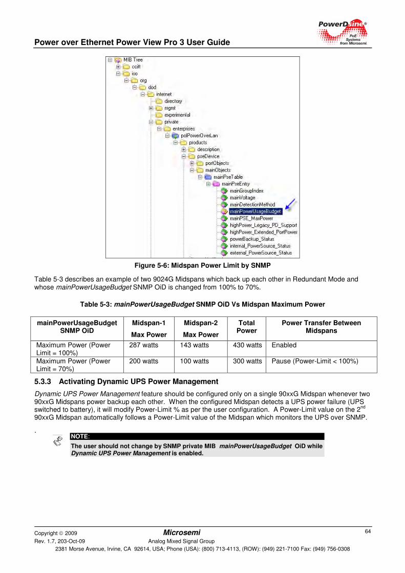
Power over Ethernet Power View Pro 3 User Guide
Copyright 2009 Microsemi Rev. 1.7, 203-Oct-09 Analog Mixed Signal Group
2381 Morse Avenue, Irvine, CA 92614, USA; Phone (USA): (800) 713-4113, (ROW): (949) 221-7100 Fax: (949) 756-0308
64
Figure 5-6: Midspan Power Limit by SNMP
Table 5-3 describes an example of two 9024G Midspans which back up each other in Redundant Mode and whose mainPowerUsageBudget SNMP OiD is changed from 100% to 70%.
Table 5-3: mainPowerUsageBudget SNMP OiD Vs Midspan Maximum Power
5.3.3 Activating Dynamic UPS Power Management
Dynamic UPS Power Management feature should be configured only on a single 90xxG Midspan whenever two 90xxG Midspans power backup each other. When the configured Midspan detects a UPS power failure (UPS switched to battery), it will modify Power-Limit % as per the user configuration. A Power-Limit value on the 2
nd
90xxG Midspan automatically follows a Power-Limit value of the Midspan which monitors the UPS over SNMP.
.
mainPowerUsageBudget SNMP OiD
Midspan-1
Max Power
Midspan-2
Max Power
Total Power
Power Transfer Between Midspans
Maximum Power (Power Limit = 100%)
287 watts 143 watts 430 watts Enabled
Maximum Power (Power Limit = 70%)
200 watts 100 watts 300 watts Pause (Power-Limit < 100%)
NOTE:
The user should not change by SNMP private MIB mainPowerUsageBudget OiD while Dynamic UPS Power Management is enabled.
Power over Ethernet Power View Pro 3 User Guide
Copyright 2009 Microsemi Rev. 1.7, 203-Oct-09 Analog Mixed Signal Group
2381 Morse Avenue, Irvine, CA 92614, USA; Phone (USA): (800) 713-4113, (ROW): (949) 221-7100 Fax: (949) 756-0308
65
5.3.4 Power Failure and Invalid Midspan to Midspan Power Backup Connection Report
� Power failure: In case of a power failure in one 90xxG Midspan units, an SNMP trap (see SNMP private MIB) and SysLog message is sent to the SNMP Manager and SysLog manager, and an error message appears in View-Status web page.
Another SNMP & SysLog message is sent whenever power is restored.
� Invalid connection: The following behavior occurs in cases where a 90xxG Midspan having a 450 watt power supply is connected to another 90xxG Midspan having 1000 watt power supply:
o Both Midspans will reduce maximum power to 41 watts which should stop power to most PoE PD devices.
o A Midspan report invalid configuration by sending SNMP Trap & SysLog message.
o An error message appears on the View->Status Web page.
o A repeating error message will appear on Terminal/Telnet/SSH screen.
NOTE:
Main Power LED will blink whenever 90xxG Midspan is being powered by external Midspan/RPS due to internal power supply failure (no AC power).
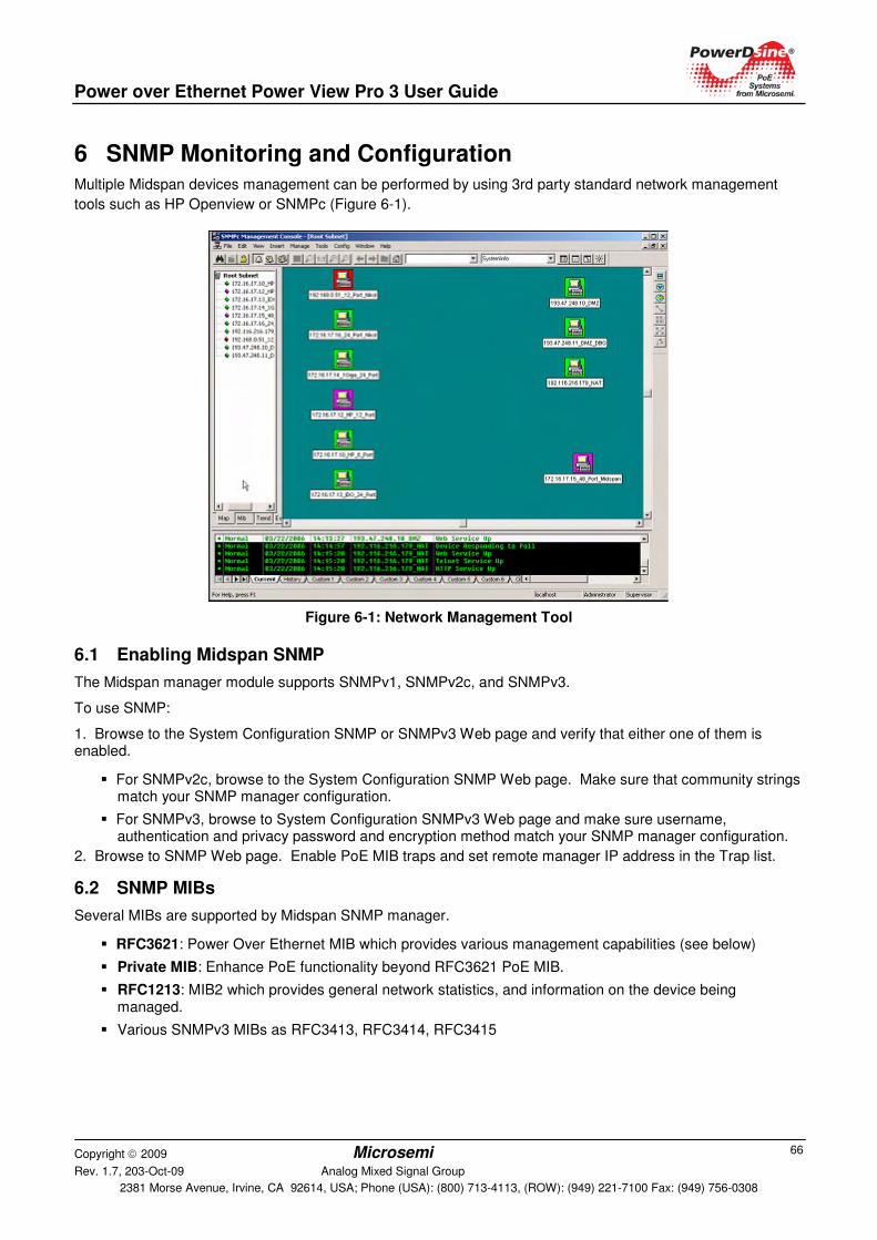
Power over Ethernet Power View Pro 3 User Guide
Copyright 2009 Microsemi Rev. 1.7, 203-Oct-09 Analog Mixed Signal Group
2381 Morse Avenue, Irvine, CA 92614, USA; Phone (USA): (800) 713-4113, (ROW): (949) 221-7100 Fax: (949) 756-0308
66
6 SNMP Monitoring and Configuration Multiple Midspan devices management can be performed by using 3rd party standard network management
tools such as HP Openview or SNMPc (Figure 6-1).
Figure 6-1: Network Management Tool
6.1 Enabling Midspan SNMP
The Midspan manager module supports SNMPv1, SNMPv2c, and SNMPv3.
To use SNMP:
1. Browse to the System Configuration SNMP or SNMPv3 Web page and verify that either one of them is enabled.
� For SNMPv2c, browse to the System Configuration SNMP Web page. Make sure that community strings match your SNMP manager configuration.
� For SNMPv3, browse to System Configuration SNMPv3 Web page and make sure username, authentication and privacy password and encryption method match your SNMP manager configuration.
2. Browse to SNMP Web page. Enable PoE MIB traps and set remote manager IP address in the Trap list.
6.2 SNMP MIBs
Several MIBs are supported by Midspan SNMP manager.
� RFC3621: Power Over Ethernet MIB which provides various management capabilities (see below)
� Private MIB: Enhance PoE functionality beyond RFC3621 PoE MIB.
� RFC1213: MIB2 which provides general network statistics, and information on the device being managed.
� Various SNMPv3 MIBs as RFC3413, RFC3414, RFC3415
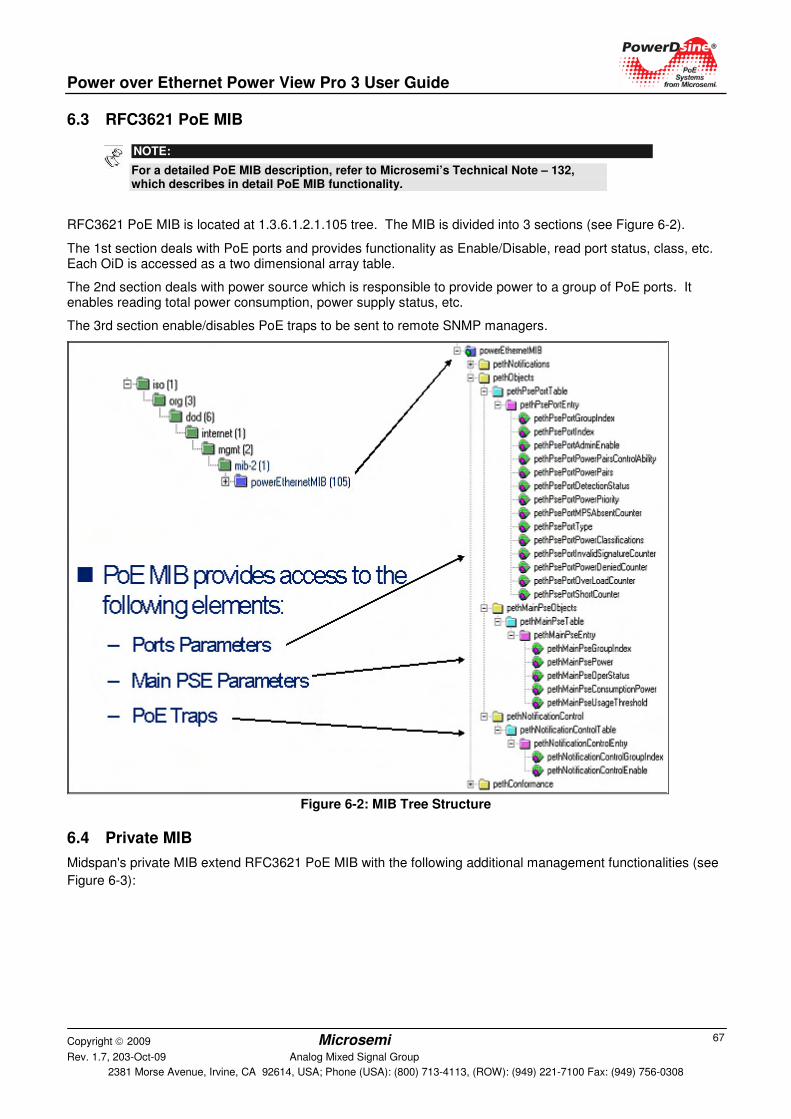
Power over Ethernet Power View Pro 3 User Guide
Copyright 2009 Microsemi Rev. 1.7, 203-Oct-09 Analog Mixed Signal Group
2381 Morse Avenue, Irvine, CA 92614, USA; Phone (USA): (800) 713-4113, (ROW): (949) 221-7100 Fax: (949) 756-0308
67
6.3 RFC3621 PoE MIB
NOTE:
For a detailed PoE MIB description, refer to Microsemi’s Technical Note – 132, which describes in detail PoE MIB functionality.
RFC3621 PoE MIB is located at 1.3.6.1.2.1.105 tree. The MIB is divided into 3 sections (see Figure 6-2).
The 1st section deals with PoE ports and provides functionality as Enable/Disable, read port status, class, etc. Each OiD is accessed as a two dimensional array table.
The 2nd section deals with power source which is responsible to provide power to a group of PoE ports. It enables reading total power consumption, power supply status, etc.
The 3rd section enable/disables PoE traps to be sent to remote SNMP managers.
Figure 6-2: MIB Tree Structure
6.4 Private MIB
Midspan's private MIB extend RFC3621 PoE MIB with the following additional management functionalities (see
Figure 6-3):
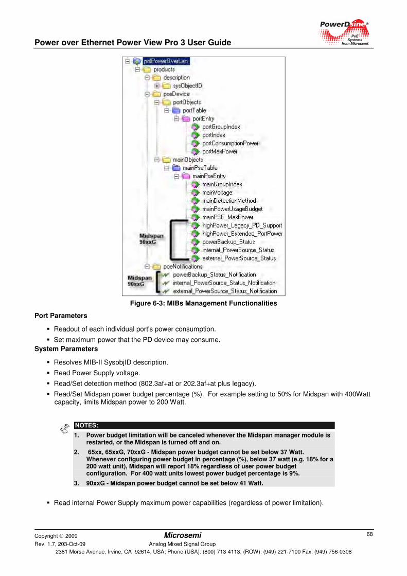
Power over Ethernet Power View Pro 3 User Guide
Copyright 2009 Microsemi Rev. 1.7, 203-Oct-09 Analog Mixed Signal Group
2381 Morse Avenue, Irvine, CA 92614, USA; Phone (USA): (800) 713-4113, (ROW): (949) 221-7100 Fax: (949) 756-0308
68
Figure 6-3: MIBs Management Functionalities
Port Parameters
� Readout of each individual port's power consumption.
� Set maximum power that the PD device may consume.
System Parameters
� Resolves MIB-II SysobjID description.
� Read Power Supply voltage.
� Read/Set detection method (802.3af+at or 202.3af+at plus legacy).
� Read/Set Midspan power budget percentage (%). For example setting to 50% for Midspan with 400Watt capacity, limits Midspan power to 200 Watt.
NOTES:
1. Power budget limitation will be canceled whenever the Midspan manager module is restarted, or the Midspan is turned off and on.
2. 65xx, 65xxG, 70xxG - Midspan power budget cannot be set below 37 Watt. Whenever configuring power budget in percentage (%), below 37 watt (e.g. 18% for a 200 watt unit), Midspan will report 18% regardless of user power budget configuration. For 400 watt units lowest power budget percentage is 9%.
3. 90xxG - Midspan power budget cannot be set below 41 Watt.
� Read internal Power Supply maximum power capabilities (regardless of power limitation).

Power over Ethernet Power View Pro 3 User Guide
Copyright 2009 Microsemi Rev. 1.7, 203-Oct-09 Analog Mixed Signal Group
2381 Morse Avenue, Irvine, CA 92614, USA; Phone (USA): (800) 713-4113, (ROW): (949) 221-7100 Fax: (949) 756-0308
69
Private MIB Object IDs which are applicable only for Midspan 90xxG:
� Enable/Disable support for various pre 802.3at PD devices.
� Enable/Disable extended power. Extend PD maximum power to 36Watt or limit to 30Watt as per 802.3at specification.
� Report power backup type (stand alone/RPS/2nd
Midspan/Invalid power backup device).
� Report internal power source status.
� Report external power source status.
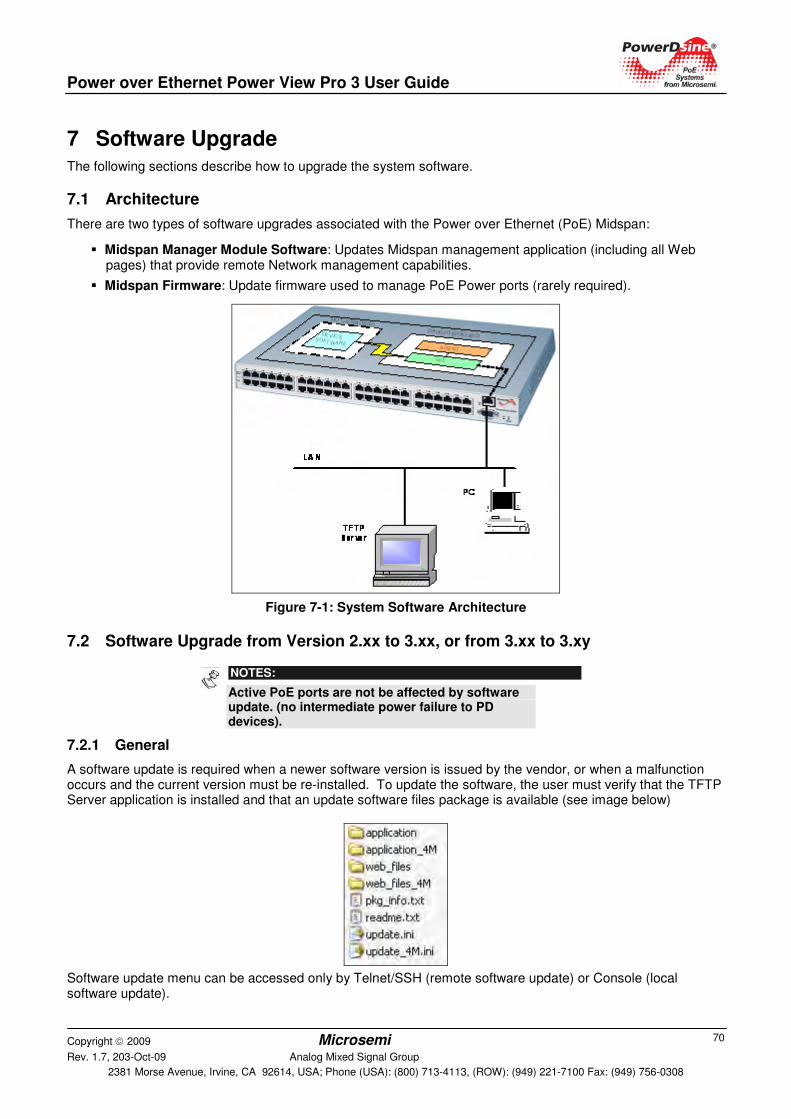
Power over Ethernet Power View Pro 3 User Guide
Copyright 2009 Microsemi Rev. 1.7, 203-Oct-09 Analog Mixed Signal Group
2381 Morse Avenue, Irvine, CA 92614, USA; Phone (USA): (800) 713-4113, (ROW): (949) 221-7100 Fax: (949) 756-0308
70
7 Software Upgrade The following sections describe how to upgrade the system software.
7.1 Architecture
There are two types of software upgrades associated with the Power over Ethernet (PoE) Midspan:
� Midspan Manager Module Software: Updates Midspan management application (including all Web pages) that provide remote Network management capabilities.
� Midspan Firmware: Update firmware used to manage PoE Power ports (rarely required).
Figure 7-1: System Software Architecture
7.2 Software Upgrade from Version 2.xx to 3.xx, or from 3.xx to 3.xy
NOTES:
Active PoE ports are not be affected by software update. (no intermediate power failure to PD devices).
7.2.1 General
A software update is required when a newer software version is issued by the vendor, or when a malfunction occurs and the current version must be re-installed. To update the software, the user must verify that the TFTP Server application is installed and that an update software files package is available (see image below)
Software update menu can be accessed only by Telnet/SSH (remote software update) or Console (local software update).
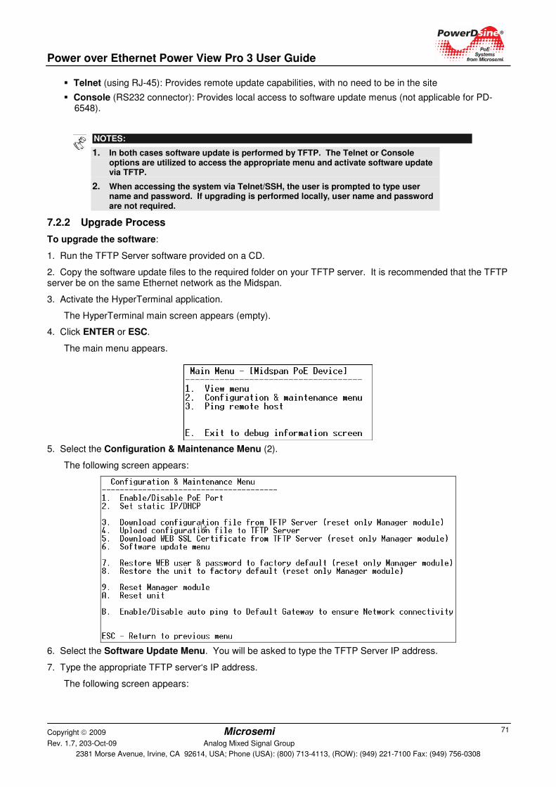
Power over Ethernet Power View Pro 3 User Guide
Copyright 2009 Microsemi Rev. 1.7, 203-Oct-09 Analog Mixed Signal Group
2381 Morse Avenue, Irvine, CA 92614, USA; Phone (USA): (800) 713-4113, (ROW): (949) 221-7100 Fax: (949) 756-0308
71
� Telnet (using RJ-45): Provides remote update capabilities, with no need to be in the site
� Console (RS232 connector): Provides local access to software update menus (not applicable for PD-6548).
NOTES:
1. In both cases software update is performed by TFTP. The Telnet or Console options are utilized to access the appropriate menu and activate software update via TFTP.
2. When accessing the system via Telnet/SSH, the user is prompted to type user name and password. If upgrading is performed locally, user name and password are not required.
7.2.2 Upgrade Process
To upgrade the software:
1. Run the TFTP Server software provided on a CD.
2. Copy the software update files to the required folder on your TFTP server. It is recommended that the TFTP server be on the same Ethernet network as the Midspan.
3. Activate the HyperTerminal application.
The HyperTerminal main screen appears (empty).
4. Click ENTER or ESC.
The main menu appears.
5. Select the Configuration & Maintenance Menu (2).
The following screen appears:
6. Select the Software Update Menu. You will be asked to type the TFTP Server IP address.
7. Type the appropriate TFTP server‘s IP address.
The following screen appears:
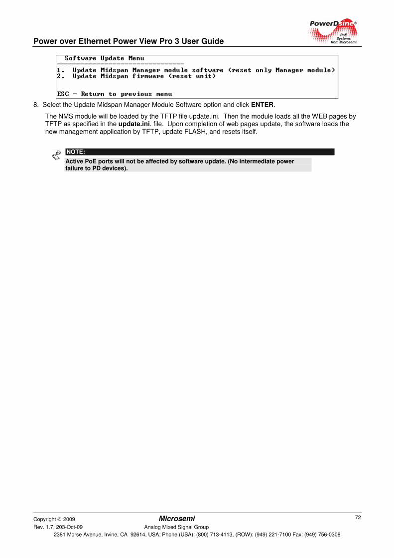
Power over Ethernet Power View Pro 3 User Guide
Copyright 2009 Microsemi Rev. 1.7, 203-Oct-09 Analog Mixed Signal Group
2381 Morse Avenue, Irvine, CA 92614, USA; Phone (USA): (800) 713-4113, (ROW): (949) 221-7100 Fax: (949) 756-0308
72
8. Select the Update Midspan Manager Module Software option and click ENTER.
The NMS module will be loaded by the TFTP file update.ini. Then the module loads all the WEB pages by TFTP as specified in the update.ini. file. Upon completion of web pages update, the software loads the new management application by TFTP, update FLASH, and resets itself.
NOTE:
Active PoE ports will not be affected by software update. (No intermediate power failure to PD devices).
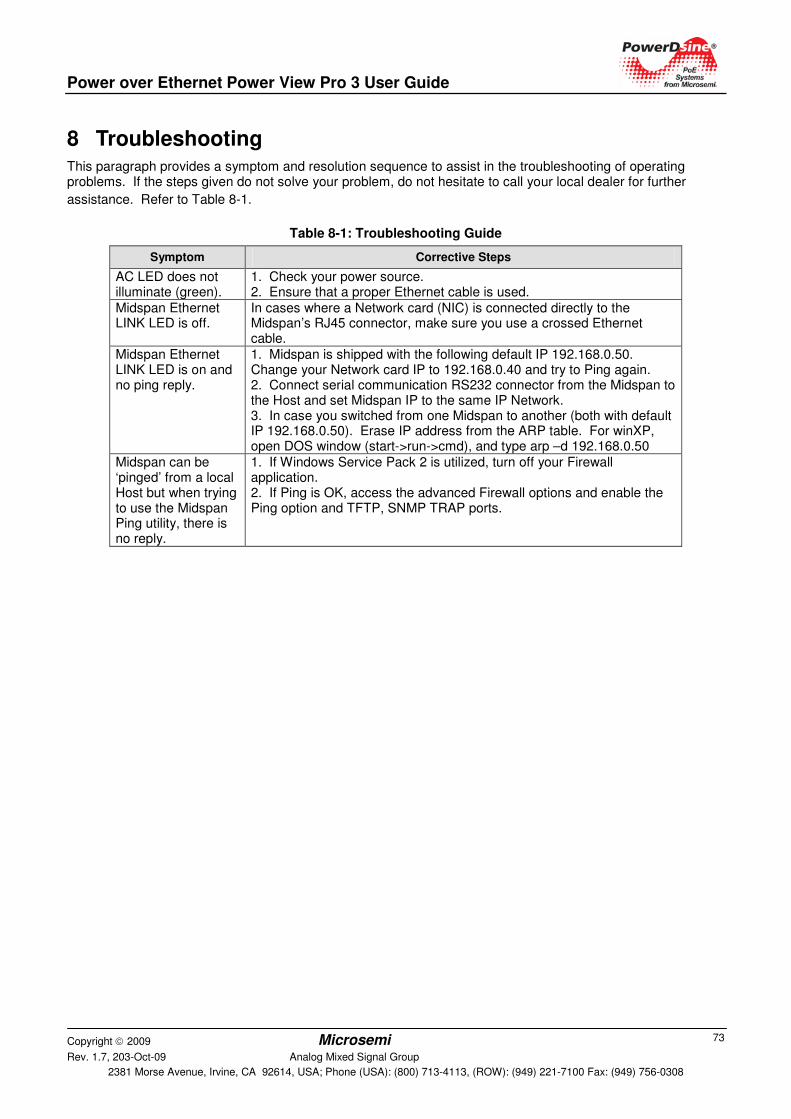
Power over Ethernet Power View Pro 3 User Guide
Copyright 2009 Microsemi Rev. 1.7, 203-Oct-09 Analog Mixed Signal Group
2381 Morse Avenue, Irvine, CA 92614, USA; Phone (USA): (800) 713-4113, (ROW): (949) 221-7100 Fax: (949) 756-0308
73
8 Troubleshooting This paragraph provides a symptom and resolution sequence to assist in the troubleshooting of operating problems. If the steps given do not solve your problem, do not hesitate to call your local dealer for further
assistance. Refer to Table 8-1.
Table 8-1: Troubleshooting Guide
Symptom Corrective Steps
AC LED does not illuminate (green).
1. Check your power source. 2. Ensure that a proper Ethernet cable is used.
Midspan Ethernet LINK LED is off.
In cases where a Network card (NIC) is connected directly to the Midspan’s RJ45 connector, make sure you use a crossed Ethernet cable.
Midspan Ethernet LINK LED is on and no ping reply.
1. Midspan is shipped with the following default IP 192.168.0.50. Change your Network card IP to 192.168.0.40 and try to Ping again. 2. Connect serial communication RS232 connector from the Midspan to the Host and set Midspan IP to the same IP Network. 3. In case you switched from one Midspan to another (both with default IP 192.168.0.50). Erase IP address from the ARP table. For winXP, open DOS window (start->run->cmd), and type arp –d 192.168.0.50
Midspan can be ‘pinged’ from a local Host but when trying to use the Midspan Ping utility, there is no reply.
1. If Windows Service Pack 2 is utilized, turn off your Firewall application. 2. If Ping is OK, access the advanced Firewall options and enable the Ping option and TFTP, SNMP TRAP ports.

Power over Ethernet Power View Pro 3 User Guide
Copyright 2009 Microsemi Rev. 1.7, 203-Oct-09 Analog Mixed Signal Group
2381 Morse Avenue, Irvine, CA 92614, USA; Phone (USA): (800) 713-4113, (ROW): (949) 221-7100 Fax: (949) 756-0308
74
Symptom Corrective Steps
Midspan is set to DHCP, but no ping from the Midspan
1. Connect serial communication RS232 connector (using a null modem cable) port to Host COM port. Select view -> Network menu. In cases where the Midspan was able to get an IP by DHCP, the following display should appear: View Network Parameters (in use)
---------------------------------------
Use DHCP : Yes
DHCP Server : 172.016.001.001
IP Address : 172.016.004.010 (valid for: 7 Days,21 Hours,6 Min,10 Sec)
Subnet Mask : 255.255.000.000
Default Gateway : 172.016.001.254
MAC Address : 00:05:5A:01:67:6F In cases where Midspan wasn't able to get IP by DHCP, the following display appears: View Network Parameters (in use)
---------------------------------------
Use DHCP : Yes
MAC Address : 00:05:5A:01:67:6F
2. Verify that the Midspan Link LED is ON and that there is a DHCP server on the network.
Software update by TFTP cannot be performed.
1. Use the Midspan Ping utility to ping the Host running the TFTP Server application 2. Turn off Firewall , or enable UDP port 69 3. Verify that appropriate update files package was copied to the TFTP Server root folder.
Unit cannot be accessed via Telnet.
Use Web browser to view System Configuration->Security WEB page and make sure that the Telnet checkbox is checked (selected).
When accessing the unit by Telnet, Telnet session is terminated each time the Configuration option is pressed.
Log-on to Telnet via the Administrator username & password option and not via the Viewer username & password.
Log-on to unit via Telnet was performed, but after a while the Telnet session is terminated.
Telnet session is terminated in cases where no key was pressed and there was no activity for over more than three (3) minutes.
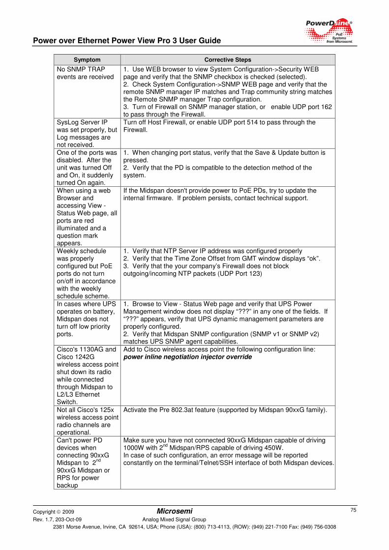
Power over Ethernet Power View Pro 3 User Guide
Copyright 2009 Microsemi Rev. 1.7, 203-Oct-09 Analog Mixed Signal Group
2381 Morse Avenue, Irvine, CA 92614, USA; Phone (USA): (800) 713-4113, (ROW): (949) 221-7100 Fax: (949) 756-0308
75
Symptom Corrective Steps
No SNMP TRAP events are received
1. Use WEB browser to view System Configuration->Security WEB page and verify that the SNMP checkbox is checked (selected). 2. Check System Configuration->SNMP WEB page and verify that the remote SNMP manager IP matches and Trap community string matches the Remote SNMP manager Trap configuration. 3. Turn of Firewall on SNMP manager station, or enable UDP port 162 to pass through the Firewall.
SysLog Server IP was set properly, but Log messages are not received.
Turn off Host Firewall, or enable UDP port 514 to pass through the Firewall.
One of the ports was disabled. After the unit was turned Off and On, it suddenly turned On again.
1. When changing port status, verify that the Save & Update button is pressed. 2. Verify that the PD is compatible to the detection method of the system.
When using a web Browser and accessing View - Status Web page, all ports are red illuminated and a question mark appears.
If the Midspan doesn't provide power to PoE PDs, try to update the internal firmware. If problem persists, contact technical support.
Weekly schedule was properly configured but PoE ports do not turn on/off in accordance with the weekly schedule scheme.
1. Verify that NTP Server IP address was configured properly 2. Verify that the Time Zone Offset from GMT window displays “ok”. 3. Verify that the your company’s Firewall does not block outgoing/incoming NTP packets (UDP Port 123)
In cases where UPS operates on battery, Midspan does not turn off low priority ports.
1. Browse to View - Status Web page and verify that UPS Power Management window does not display “???” in any one of the fields. If “???” appears, verify that UPS dynamic management parameters are properly configured. 2. Verify that Midspan SNMP configuration (SNMP v1 or SNMP v2) matches UPS SNMP agent capabilities.
Cisco's 1130AG and Cisco 1242G wireless access point shut down its radio while connected through Midspan to L2/L3 Ethernet Switch.
Add to Cisco wireless access point the following configuration line: power inline negotiation injector override
Not all Cisco's 125x wireless access point radio channels are operational.
Activate the Pre 802.3at feature (supported by Midspan 90xxG family).
Can't power PD devices when connecting 90xxG Midspan to 2
nd
90xxG Midspan or RPS for power backup
Make sure you have not connected 90xxG Midspan capable of driving 1000W with 2
nd Midspan/RPS capable of driving 450W.
In case of such configuration, an error message will be reported constantly on the terminal/Telnet/SSH interface of both Midspan devices.

Power over Ethernet Power View Pro 3 User Guide
Copyright 2009 Microsemi Rev. 1.7, 203-Oct-09 Analog Mixed Signal Group
2381 Morse Avenue, Irvine, CA 92614, USA; Phone (USA): (800) 713-4113, (ROW): (949) 221-7100 Fax: (949) 756-0308
76
Symptom Corrective Steps
90xxG Midspan was connected to another 90xxG Midspan/RPS but operates as stand alone Midspan
Make sure that you have connected power cables and communication cable between 1
st Midspan to 2
nd Midspan/RPS
Power over Ethernet Power View Pro 3 User Guide
Copyright 2009 Microsemi Rev. 1.7, 203-Oct-09 Analog Mixed Signal Group
2381 Morse Avenue, Irvine, CA 92614, USA; Phone (USA): (800) 713-4113, (ROW): (949) 221-7100 Fax: (949) 756-0308
77
The information contained in the document is PROPRIETARY AND CONFIDENTIAL information of Microsemi and cannot be copied, published, uploaded, posted, transmitted, distributed or disclosed or used without the express duly signed written consent of Microsemi If the recipient of this document has entered into a disclosure agreement with Microsemi, then the terms of such Agreement will also apply . This document and the information contained herein may not be modified, by any person other than authorized personnel of Microsemi. No license under any patent, copyright, trade secret or other intellectual property right is granted to or conferred upon you by disclosure or delivery of the information, either expressly, by implication, inducement, estoppels or otherwise. Any license under such intellectual property rights must be express and approved by Microsemi in writing signed by an officer of Microsemi.
Microsemi reserves the right to change the configuration, functionality and performance of its products at anytime without any notice. This product has been subject to limited testing and should not be used in conjunction with life-support or other mission-critical equipment or applications. Microsemi assumes no liability whatsoever, and Microsemi disclaims any express or implied warranty, relating to sale and/or use of Microsemi products including liability or warranties relating to fitness for a particular purpose, merchantability, or infringement of any patent, copyright or other intellectual property right. The product is subject to other terms and conditions which can be located on the web at http://www.microsemi.com/legal/tnc.asp.
Revision History
Revision Level / Date
Para. Affected
Description
1.5 Whole Document
Formatting
1.6 Whole Document
Add 90xxG Midspan
1.7 Whole Document
Add 65xxG Midspan. Modify 70xxG Midspan description
Covered under one or more of US Patents: #6,473,608; 6,986,071; 7,006,815; 7,254,734; 7,257,724; 7,259,325, 7,305,573; 7,325,150; 7,421,290, 7,437,217.
© 2009 Microsemi Corp.
All rights reserved.
For support contact: [email protected]
Visit our web site at: http://www.microsemi.com/PowerDsine/Support/
Catalog Number: 06-0051-056