Power Optimised Aircraft - aerodays2006.orgaerodays2006.org/sessions/E_Sessions/E6/E61.pdf · Power...
19
Power Optimised Aircraft A keystone in European research in More Electric Aircraft Equipment Systems Aerodays 2006 Vienna, 20 June 2006 Lester Faleiro, PhD, MIEE Liebherr –Aerospace Progress in Motion Air Management. Actuation and Flight Control. Landing Gear. www.liebherr.com
Transcript of Power Optimised Aircraft - aerodays2006.orgaerodays2006.org/sessions/E_Sessions/E6/E61.pdf · Power...
Power Optimised Aircraft Aerodays 2006, Vienna, 20 June 2006
DO-06-T-F&T 0601 / 20.6.2006©LIEBHERR-AEROSPACE 2006 1
Power Optimised AircraftA keystone in European research in More Electric Aircraft Equipment Systems
Aerodays 2006Vienna, 20 June 2006
Lester Faleiro, PhD, MIEELiebherr –Aerospace
Progress in MotionAir Management. Actuation and Flight Control. Landing Gear.
www.liebherr.com
Power Optimised Aircraft Aerodays 2006, Vienna, 20 June 2006
DO-06-T-F&T 0601 / 20.6.2006©LIEBHERR-AEROSPACE 2006 2
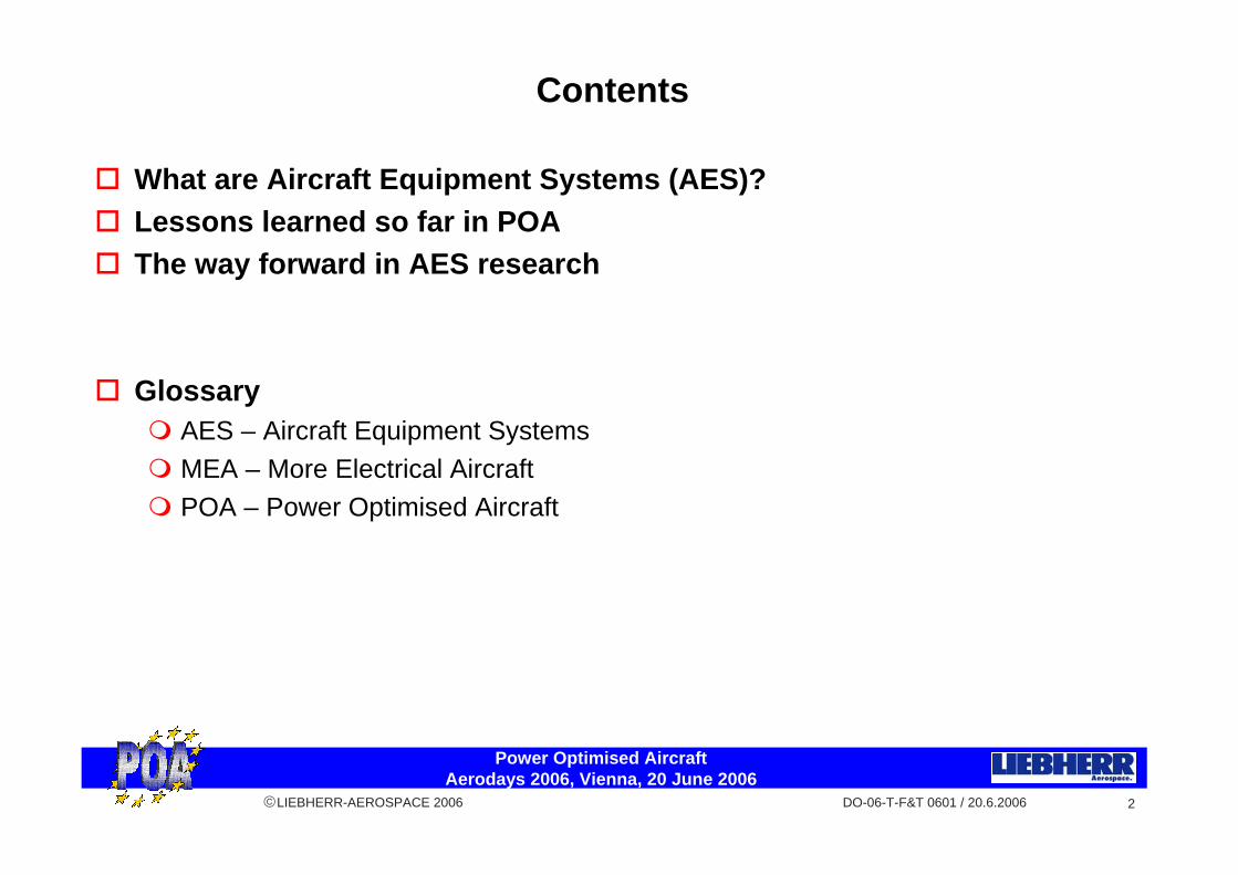
Contents
What are Aircraft Equipment Systems (AES)?Lessons learned so far in POAThe way forward in AES research
GlossaryAES – Aircraft Equipment SystemsMEA – More Electrical AircraftPOA – Power Optimised Aircraft

Power Optimised Aircraft Aerodays 2006, Vienna, 20 June 2006
DO-06-T-F&T 0601 / 20.6.2006©LIEBHERR-AEROSPACE 2006 3
Engine
Primary Controls
Engine systems
Wing Anti-Ice
Primary Controls
Secondary Controls
Environmental Control
Landing Gear
APU
Gearbox
Electrical Distribution
Central Hydraulics
Commercial Loads
Generator
Mechanical Power
Hydraulic Power
Pneumatic Power
Electrical Power
What are Aircraft Equipment Systems (AES)?
“Systems required to ensure safe and
comfortable flight”
Power Optimised Aircraft Aerodays 2006, Vienna, 20 June 2006
DO-06-T-F&T 0601 / 20.6.2006©LIEBHERR-AEROSPACE 2006 4
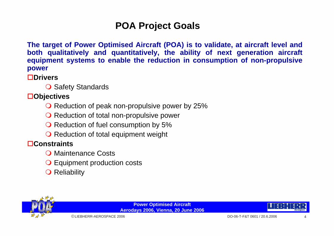
The target of Power Optimised Aircraft (POA) is to validate, at aircraft level and both qualitatively and quantitatively, the ability of next generation aircraft equipment systems to enable the reduction in consumption of non-propulsive power
DriversSafety Standards
ObjectivesReduction of peak non-propulsive power by 25%Reduction of total non-propulsive powerReduction of fuel consumption by 5%Reduction of total equipment weight
ConstraintsMaintenance CostsEquipment production costsReliability
POA Project Goals
Power Optimised Aircraft Aerodays 2006, Vienna, 20 June 2006
DO-06-T-F&T 0601 / 20.6.2006©LIEBHERR-AEROSPACE 2006 5
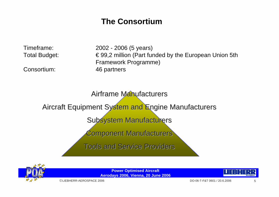
Timeframe: 2002 - 2006 (5 years)Total Budget: € 99,2 million (Part funded by the European Union 5th
Framework Programme)Consortium: 46 partners
Airframe ManufacturersAirframe Manufacturers
Aircraft Equipment System and Engine ManufacturersAircraft Equipment System and Engine Manufacturers
Subsystem ManufacturersSubsystem Manufacturers
Component ManufacturersComponent Manufacturers
Tools and Service ProvidersTools and Service Providers
The Consortium

Power Optimised Aircraft Aerodays 2006, Vienna, 20 June 2006
DO-06-T-F&T 0601 / 20.6.2006©LIEBHERR-AEROSPACE 2006 6
Engine
Primary Controls
Engine systems
Wing Anti-Ice
Primary Controls
Secondary Controls
Environmental Control
Landing Gear
APU
Gearbox
Electrical Distribution
Central Hydraulics
Commercial Loads
Generator
Mechanical Power
Hydraulic Power
Pneumatic Power
Electrical Power
Conventional Aircraft Architecture

Power Optimised Aircraft Aerodays 2006, Vienna, 20 June 2006
DO-06-T-F&T 0601 / 20.6.2006©LIEBHERR-AEROSPACE 2006 7
Environmental Control
Primary Controls
Engine systems
Wing Anti-Ice
Primary Controls
Secondary Controls
Landing Gear
Commercial Loads
Cabin Expansion generator
Electrical Distribution
Starter Generator
Engine
Local Hydraulic source
Local Compressor
More Electrical Power
No Gearbox
Reduced Engine Bleed
Optimised Aircraft Architecture?
Power Optimised Aircraft Aerodays 2006, Vienna, 20 June 2006
DO-06-T-F&T 0601 / 20.6.2006©LIEBHERR-AEROSPACE 2006 8
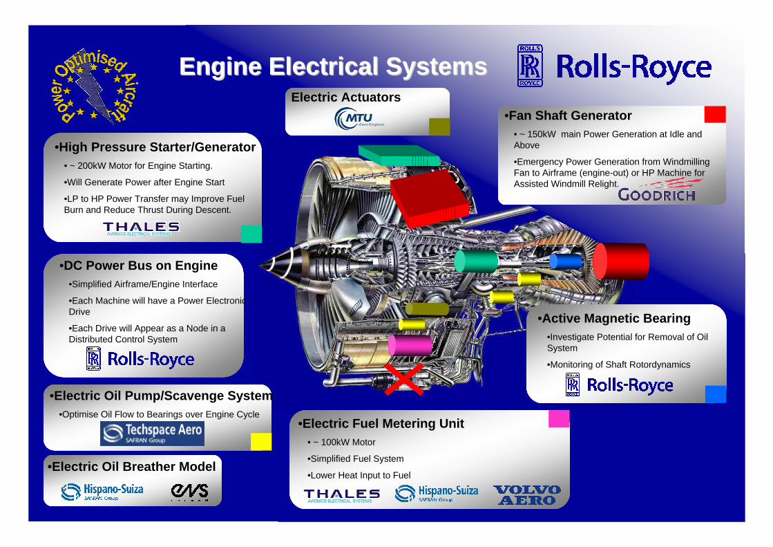
EngineEngine ElectricalElectrical SystemsSystems
•DC Power Bus on Engine•Simplified Airframe/Engine Interface
•Each Machine will have a Power Electronic Drive
•Each Drive will Appear as a Node in a Distributed Control System
•Fan Shaft Generator• ~ 150kW main Power Generation at Idle and Above
•Emergency Power Generation from Windmilling Fan to Airframe (engine-out) or HP Machine for Assisted Windmill Relight.
•Active Magnetic Bearing•Investigate Potential for Removal of Oil System
•Monitoring of Shaft Rotordynamics
•Electric Fuel Metering Unit• ~ 100kW Motor
•Simplified Fuel System
•Lower Heat Input to Fuel
•Electric Oil Pump/Scavenge System•Optimise Oil Flow to Bearings over Engine Cycle
Electric Actuators
•High Pressure Starter/Generator• ~ 200kW Motor for Engine Starting.
•Will Generate Power after Engine Start
•LP to HP Power Transfer may Improve Fuel Burn and Reduce Thrust During Descent.
•Electric Oil Breather Model
Power Optimised Aircraft Aerodays 2006, Vienna, 20 June 2006
DO-06-T-F&T 0601 / 20.6.2006©LIEBHERR-AEROSPACE 2006 9
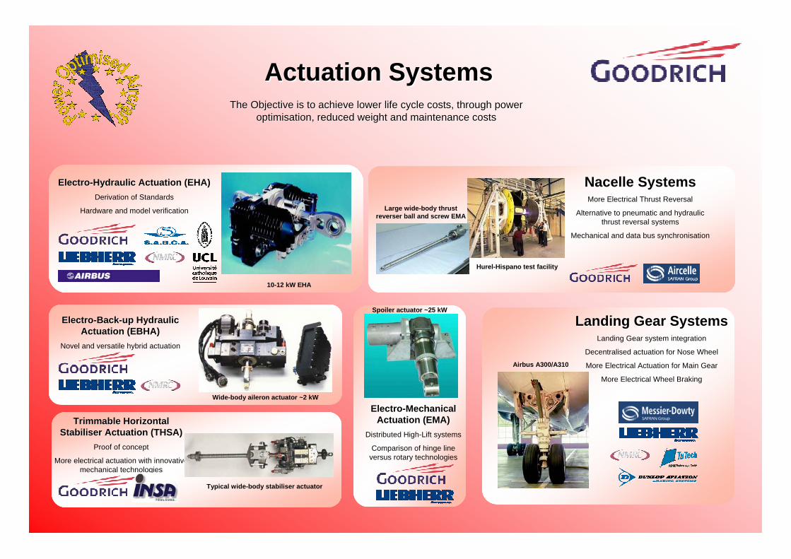
ActuationActuation SystemsSystemsTheThe ObjectiveObjective isis to to achieveachieve lowerlower life life cyclecycle costscosts, , throughthrough powerpower
optimisationoptimisation, , reducedreduced weightweight and and maintenancemaintenance costscosts
PrimaryPrimary & & SecondarySecondary FlightFlight ControlControl SystemsSystems
TrimmableTrimmable Horizontal Horizontal StabiliserStabiliser ActuationActuation (THSA)(THSA)
Proof of concept
More electrical actuation with innovative mechanical technologies
ElectroElectro--MechanicalMechanicalActuationActuation (EMA)(EMA)
Distributed High-Lift systems
Comparison of hinge lineversus rotary technologies
ElectroElectro--HydraulicHydraulic ActuationActuation (EHA)(EHA)Derivation of Standards
Hardware and model verification
ElectroElectro--BackBack--upup HydraulicHydraulicActuationActuation (EBHA)(EBHA)
Novel and versatile hybrid actuation
LandingLanding GearGear SystemsSystemsLanding Gear system integration
Decentralised actuation for Nose Wheel
More Electrical Actuation for Main Gear
More Electrical Wheel Braking
NacelleNacelle SystemsSystemsMore Electrical Thrust Reversal
Alternative to pneumatic and hydraulicthrust reversal systems
Mechanical and data bus synchronisation
10-12 kW EHA
Wide-body aileron actuator ~2 kW
Typical wide-body stabiliser actuator
Spoiler actuator ~25 kW
Large wide-body thrustreverser ball and screw EMA
Hurel-Hispano test facility
Airbus A300/A310

Power Optimised Aircraft Aerodays 2006, Vienna, 20 June 2006
DO-06-T-F&T 0601 / 20.6.2006©LIEBHERR-AEROSPACE 2006 10
The Objective is to reduce and optimise the effect of bleed air off-take on power usage, as this is a large consumer of non-propulsive power. Bleed Air Off-Takes are
mainly used for the Environment Control System and for Wing Ice Protection.
PneumaticPneumatic SystemsSystems
Wing Ice Protection (WIP)Wing Ice Protection (WIP)To Increase the efficiency of WIP Systems
The main innovation is the use of ultrasonic surface ice sensors (WIP on demand) and hybrid wing heating (electrical and hot air)
The main outputs are Model of WIP Systems and Test of an innovative WIP System
Wing heat distribution using: Ultrasonic sensors, Electro-thermal devices, On demand active intelligence control and Monitoring ofunprotected surfaces
Motorised Air Cycle machine
Re-circulation Fan
CO2 Compressor
Fuel Cells (FC)Fuel Cells (FC)
To Increase the efficiency of electrical power generation for pneumatic systems
The main innovation is the validation of a Solid Oxide Fuel Cell(SOFC) with its reformer for use with kerosene
The main outputs are a Model of FC System and the Test of a 5 kW Fuel Cell System
EnvEnv. Conditioning System (ECS). Conditioning System (ECS)To increase the efficiency of the ACS
The main innovation is the combination of a Vapour Cycle (containing an environmentally neutral fluid) with an electrical driven Air Cycle. A variable speed motor for the re-circulation fan and a Cabin Energy Recovery Device will be used.
The main outputs are a Model of a complete ACS and the Test of a Hybrid ACS (Vapour +Air Cycle)
Ice detection sensor
SOFC Principle

Pneumatic Systems
Aircraft Electrical Power Systems
Engine Electrical Systems
Actuation Systems
A Total A Total AircraftAircraft RepresentativeRepresentativePhilosophyPhilosophy
Mod
els
Mod
els
Mo d
els
Mo d
els
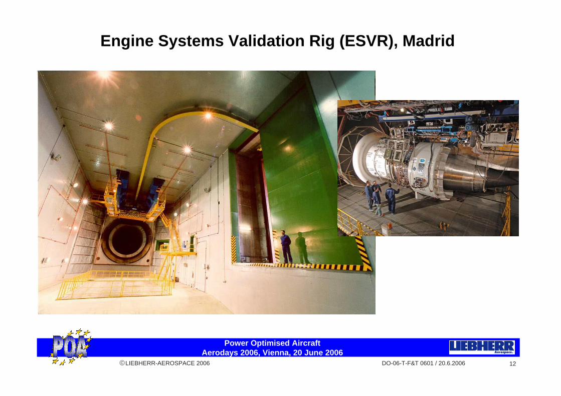
EngineEngine Systems Validation Systems Validation RigRig(ESVR) at INTA(ESVR) at INTA
AircraftAircraft Systems Validation Systems Validation RigRig(ASVR) at (ASVR) at HispanoHispano--SuizaSuiza
VirtualVirtual Iron Iron BirdBird (VIB), (VIB), firstfirst at DLR, at DLR, thenthen in in realreal--timetime at at HispanoHispano--SuizaSuiza
Engine
LandingGear
PrimaryControls
PrimaryControls
SecondaryControls
APU
ElectricalDistribution
Commercial Loads
Enginesystems
WingAnti-Ice
EnvironmentalControl
Gearbox
Central Hydraulics
Generator
Selectedsuite of Validated
Hardw
are subsystems
and components
Full suite of Validatedsystem
and subsystemm
odels
I I -- Each of the Technical Work Packages will produce Each of the Technical Work Packages will produce validated hardware and models from their respective validated hardware and models from their respective systems areas. These will be integrated into the ESVR, systems areas. These will be integrated into the ESVR, ASVR and VIB ASVR and VIB
II II -- The ESVR and ASVR will each be run to validate The ESVR and ASVR will each be run to validate systems integration (an identical generator will be used systems integration (an identical generator will be used on both in order to produce comparable results). on both in order to produce comparable results). Hardware absent from the ASVR will be modelled in Hardware absent from the ASVR will be modelled in realreal--time on the VIB and run together with the ASVR to time on the VIB and run together with the ASVR to represent a total aircraft.represent a total aircraft.
III III -- The VIB will be used to validate that the resulting The VIB will be used to validate that the resulting aircraft system is optimisedaircraft system is optimised
Note: Pictures shown do not necessarily indicate the exact hardware involved in POA
Power Optimised Aircraft Aerodays 2006, Vienna, 20 June 2006
DO-06-T-F&T 0601 / 20.6.2006©LIEBHERR-AEROSPACE 2006 12
Engine Systems Validation Rig (ESVR), Madrid

Power Optimised Aircraft Aerodays 2006, Vienna, 20 June 2006
DO-06-T-F&T 0601 / 20.6.2006©LIEBHERR-AEROSPACE 2006 13
Aircraft Systems Validation Rig (ASVR), Paris

Power Optimised Aircraft Aerodays 2006, Vienna, 20 June 2006
DO-06-T-F&T 0601 / 20.6.2006©LIEBHERR-AEROSPACE 2006 14
Virtual Iron Bird (VIB), Munich
Power Optimised Aircraft Aerodays 2006, Vienna, 20 June 2006
DO-06-T-F&T 0601 / 20.6.2006©LIEBHERR-AEROSPACE 2006 15
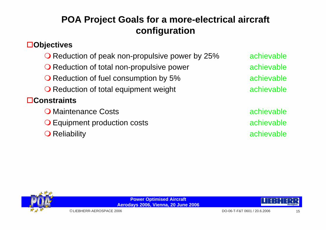
ObjectivesReduction of peak non-propulsive power by 25% achievableReduction of total non-propulsive power achievableReduction of fuel consumption by 5% achievableReduction of total equipment weight achievable
ConstraintsMaintenance Costs achievableEquipment production costs achievableReliability achievable
POA Project Goals for a more-electrical aircraft configuration

Power Optimised Aircraft Aerodays 2006, Vienna, 20 June 2006
DO-06-T-F&T 0601 / 20.6.2006©LIEBHERR-AEROSPACE 2006 16
Why is POA a keystone?
Previous projects concentrated on systems level researchPOA was the first big European integration level projectPOA confirmed the feasibility of MEAPOA showed that we need to concentrate on
Understanding the management of electrical loadsSolving thermal management issuesEnabling technologies such as power electronics
This led to More Open Electrical Technologies (MOET, FP6)Examine electrical architecturesExplore thermal managementUtilise current advances in power electronics technologies
The next step is „Clean Sky“ (FP7)Validation of total energy managementMaturation of the work begun in POAValidation of the ideas generated in POA

Power Optimised Aircraft Aerodays 2006, Vienna, 20 June 2006
DO-06-T-F&T 0601 / 20.6.2006©LIEBHERR-AEROSPACE 2006 17
2004 2008
Systems for MEA
MEA Integration
MEA Process
1996 2000 2012
EU framework programmes
1992
C-141 demoCC--141 demo141 demo
FP4 FP5
MEA (US AFRL)MEA (US AFRL)MEA (US AFRL)
LEMASLEMASLEMAS
EPADEPADEPAD
HEATHEATHEATEABSYSEABSYSEABSYS
TIMES (UK)TIMES (UK)TIMES (UK)F-16/F-18 demoFF--16/F16/F--18 demo18 demo POA (EC)POA (EC)POA (EC)
REACTSREACTSREACTS
DEPMADEPMADEPMAVFCFCVFCFCVFCFC
MOET (EC)MOET (EC)MOET (EC)
ELISAELISAELISAEPICAEPICAEPICA
FP6
VFGVFGVFG
IHPTETIHPTETIHPTET VAATEVAATEVAATEEEFAEEEFAEEEFAE
FP7
Systems projects
Integration Integration projectsprojects
Clean Sky (EC)Clean Sky (EC)Clean Sky (EC)
MEA II (US AFRL)MEA II (US AFRL)MEA II (US AFRL)
Why is POA a keystone?
A320 demoA320 demoA320 demo

Power Optimised Aircraft Aerodays 2006, Vienna, 20 June 2006
DO-06-T-F&T 0601 / 20.6.2006©LIEBHERR-AEROSPACE 2006 18
More information on POA project results
TEOS forum, 28-30 June 2006Technologies for Energy OptimisedAircraft Equipment Systems
POA results in the form of seminars, workshops, exhibitionHotel Novotel Tour Eiffel, Paris, France

Power Optimised Aircraft Aerodays 2006, Vienna, 20 June 2006
DO-06-T-F&T 0601 / 20.6.2006©LIEBHERR-AEROSPACE 2006 19
© Liebherr-Aerospace 2006. Alle Rechte vorbehalten.Kein Teil dieses Dokumentes darf in irgendwelcher Form wiedergegeben oder unterVerwendung irgendwelcher Übermittlungsmittel übermittelt werden, einschliesslich derHerstellung von Photokopien, der Herstellung von Aufnahmen und sämtlicher anderer Formender Speicherung und Wiedergabe, ohne zuvor die schriftliche Genehmigung der Liebherr-Aerospace erhalten zu haben.
© Liebherr-Aerospace 2006. Tous droits réservés.Aucune partie de ce document ne peut être reproduite ou transmise sous quelque forme que ce soit ou par n’importe quel moyen de reproduction ou transmission, électronique ou mécanique y compris photocopies, enregistrements et toute autre forme de mémorisation et transmission, sans préalablement avoir obtenu l’accord écrit de Liebherr-Aerospace à cet effet.
© Liebherr-Aerospace 2006. All rights reserved.No part of this document may be reproduced or transmitted in any form or by any means, electronic or mechanical, including photocopy, recording, or any information storage and retrieval system, without prior written permission from Liebherr-Aerospace.


![I-400 Japan's Secret Aircraft-Carrying Strike Submarine [Hikoki 2006]](https://static.fdocuments.net/doc/165x107/55721313497959fc0b918beb/i-400-japans-secret-aircraft-carrying-strike-submarine-hikoki-2006.jpg)