POWER-LOCK - Tsubaki
88
POWER-LOCK
Transcript of POWER-LOCK - Tsubaki
POWER-LOCK
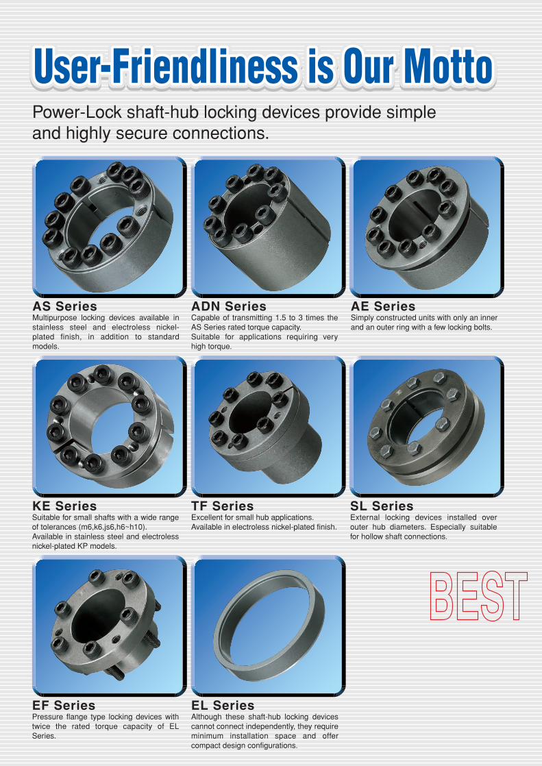
Power-Lock shaft-hub locking devices provide simple and highly secure connections.
ADN SeriesCapable of transmitting 1.5 to 3 times the AS Series rated torque capacity. Suitable for applications requiring very high torque.
AE SeriesSimply constructed units with only an inner and an outer ring with a few locking bolts.
AS SeriesMultipurpose locking devices available in stainless steel and electroless nickel-plated finish, in addition to standard models.
KE SeriesSuitable for small shafts with a wide range of tolerances (m6,k6,js6,h6~h10).Available in stainless steel and electroless nickel-plated KP models.
TF Series�Excellent for small hub applications.Available in electroless nickel-plated finish.
EF SeriesPressure flange type locking devices with twice the rated torque capacity of EL Series.
EL Series�Although these shaft-hub locking devices cannot connect independently, they require minimum installation space and offer compact design configurations.
SL SeriesExternal locking devices installed over outer hub diameters. Especially suitable for hollow shaft connections.
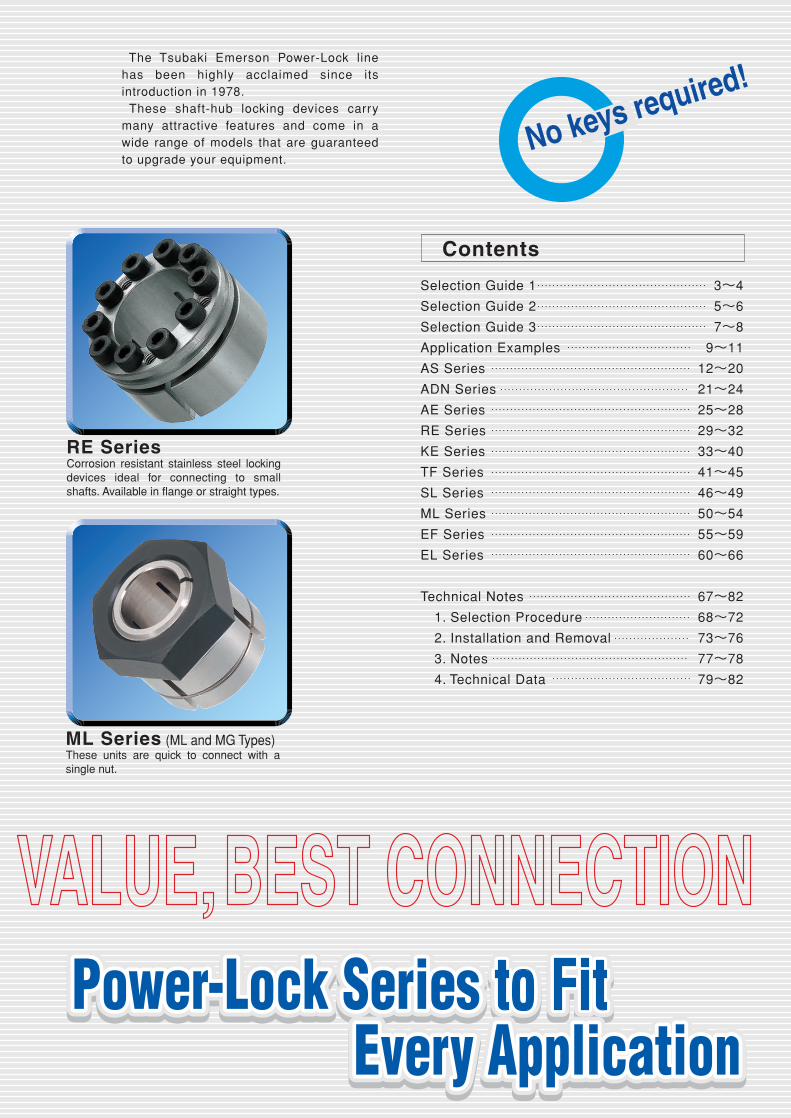
RE SeriesCorrosion resistant stainless steel locking devices ideal for connecting to small shafts. Available in flange or straight types.
ML Series (ML and MG Types)These units are quick to connect with a single nut.
The Tsubaki Emerson Power-Lock line has been highly acclaimed since its introduction in 1978. These shaft-hub locking devices carry many attractive features and come in a wide range of models that are guaranteed to upgrade your equipment.
Contents
Selection Guide 1 3~4
Selection Guide 2 5~6
Selection Guide 3 7~8
Application Examples 9~11
AS Series 12~20
ADN Series 21~24
AE Series 25~28
RE Series 29~32
KE Series 33~40
TF Series 41~45
SL Series 46~49
ML Series 50~54
EF Series 55~59
EL Series 60~66
Technical Notes 67~82
1. Selection Procedure 68~72
2. Installation and Removal 73~76
3. Notes 77~78
4. Technical Data 79~82
No keys required!
3
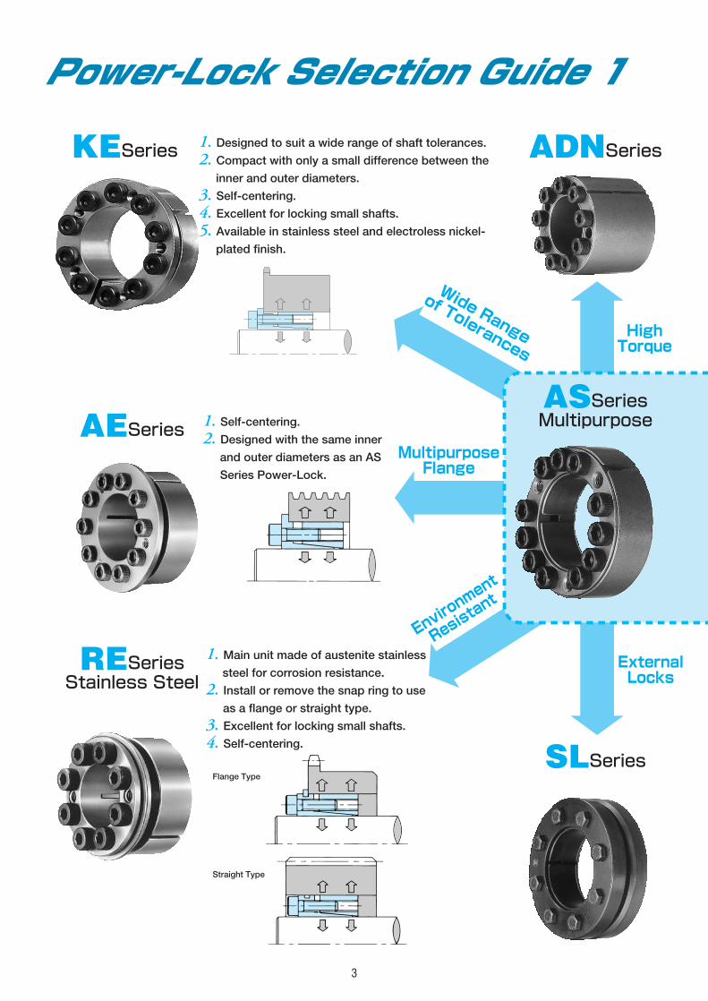
1. Designed to suit a wide range of shaft tolerances.2. Compact with only a small difference between theinner and outer diameters.
3. Self-centering.4. Excellent for locking small shafts.5. Available in stainless steel and electroless nickel-plated finish.
1. Self-centering.2. Designed with the same innerand outer diameters as an AS
Series Power-Lock.
1. Main unit made of austenite stainlesssteel for corrosion resistance.
2. Install or remove the snap ring to useas a flange or straight type.
3. Excellent for locking small shafts.4. Self-centering.
KESeries ADNSeries
AESeries
RESeriesStainless Steel
Flange Type
Straight Type
ASSeriesMultipurpose
SLSeries
Wide Range
of Tolerances
MultipurposeFlange
Environment
Resistant
Power-Lock Selection Guide 1
HighTorque
ExternalLocks
4
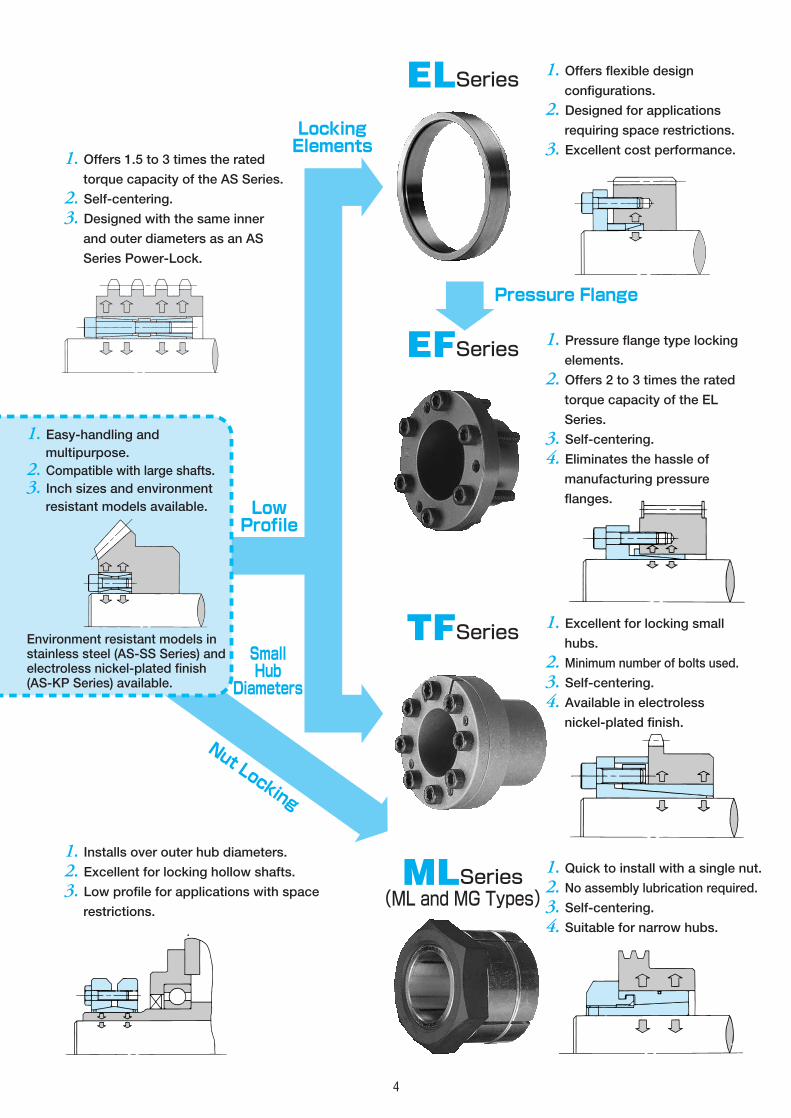
1. Offers 1.5 to 3 times the ratedtorque capacity of the AS Series.
2. Self-centering.3. Designed with the same innerand outer diameters as an AS
Series Power-Lock.
1. Installs over outer hub diameters.2. Excellent for locking hollow shafts.3. Low profile for applications with spacerestrictions.
1. Offers flexible designconfigurations.
2. Designed for applicationsrequiring space restrictions.
3. Excellent cost performance.
1. Pressure flange type lockingelements.
2. Offers 2 to 3 times the ratedtorque capacity of the EL
Series.
3. Self-centering.4. Eliminates the hassle ofmanufacturing pressure
flanges.
1. Excellent for locking smallhubs.
2. Minimum number of bolts used.3. Self-centering.4. Available in electrolessnickel-plated finish.
1. Quick to install with a single nut.2. No assembly lubrication required.3. Self-centering.4. Suitable for narrow hubs.
ELSeries
EFSeries
TFSeries
1. Easy-handling andmultipurpose.
2. Compatible with large shafts.3. Inch sizes and environmentresistant models available.
Environment resistant models instainless steel (AS-SS Series) andelectroless nickel-plated finish(AS-KP Series) available.
MLSeries(ML and MG Types)
LowProfile
Pressure Flange
LockingElements
SmallHub
Diameters
Nut Locking

5
Power-Lock Selection Guide 2
※See section for KE Series.
SeriesHub
Movement
Transmissible
Thrust kN
Self-
Centering
Shaft/Hub
Tolerances
Surface
RoughnessLubrication
Ambient
Temp.
N/A
26.5~1000
N/A(A precenteredhub is required.)
h8/H8
Below 12S
Required
-30 ℃~200 ℃
N/R
21.6~278
40.6~2600
Yes
Required
28.1~361
None,withsnap ring 1.89~
76.3N/R
Some,withoutsnap ring
N/A
2.86~187
※h10~m6 Required
h8/H8
N/R
1.89~31.6
※h10~m6
3.78~196
h8/H8
Required
8.70~196
N/R17.9~
2370─ h6/H7/h7
Somemovement.
2.65~56
Yes h8/H8
7.79~211
RequiredYes,if pressureis applied onthe inner ring. 1.37~
140
N/A(A precenteredhub is required.)
h6/H7h8/H8
Below 6SNo,if pressureis applied onthe outer ring.
Multipurpose
AS
High Torque
ADNMultipurpose Flange
AE
Wide range of Tolerances
KE
RE-SS
KE-KP
TF-KP
KE-SS
Locking Elements
EL
Pressure Flange
EF
Small Hub Diametrs
TF
Nut Locking
ML(ML and MG Types)
External Locks
SL
AS-ss
Environment Resistant
AS-KP(Electroless Nickel-Plated)
Environment Resistant(Electroless Nickel-Plated)
Environment Resistant(Electroless Nickel-Plated)
Environment Resistant(Stainless Steel)
Environment Resistant(Stainless Steel)
Environment Resistant(Stainless Steel)
6
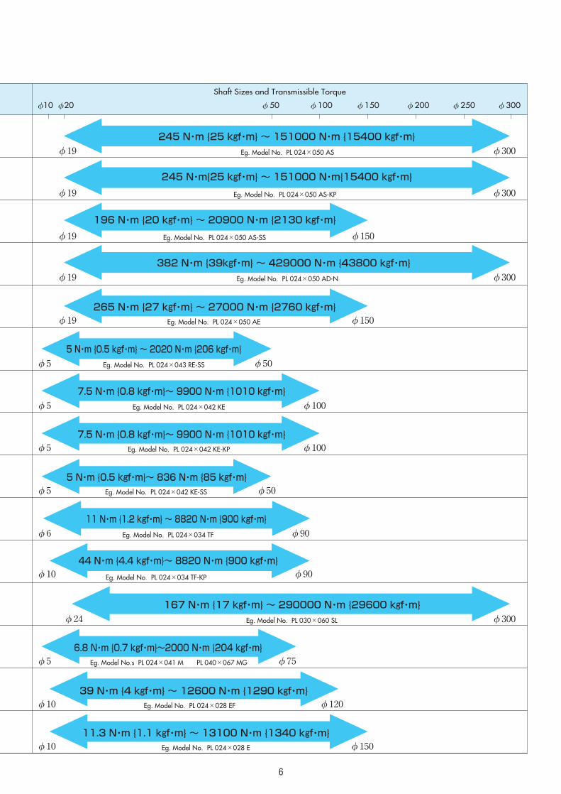
Shaft Sizes and Transmissible Torque
φ10 φ20 φ50 φ100 φ150 φ200 φ250 φ300
245 N・m {25 kgf・m} ~ 151000 N・m {15400 kgf・m}
245 N・m{25 kgf・m} ~ 151000 N・m{15400 kgf・m}
196 N・m {20 kgf・m} ~ 20900 N・m {2130 kgf・m}
382 N・m {39kgf・m} ~ 429000 N・m {43800 kgf・m}
265 N・m {27 kgf・m} ~ 27000 N・m {2760 kgf・m}
7.5 N・m {0.8 kgf・m}~ 9900 N・m {1010 kgf・m}
7.5 N・m {0.8 kgf・m}~ 9900 N・m {1010 kgf・m}
5 N・m {0.5 kgf・m} ~ 2020 N・m {206 kgf・m}
11.3 N・m {1.1 kgf・m} ~ 13100 N・m {1340 kgf・m}
39 N・m {4 kgf・m} ~ 12600 N・m {1290 kgf・m}
11 N・m {1.2 kgf・m} ~ 8820 N・m {900 kgf・m}
6.8 N・m {0.7 kgf・m}~2000 N・m {204 kgf・m}
167 N・m {17 kgf・m} ~ 290000 N・m {29600 kgf・m}
Eg. Model No. PL 024×050 AS
Eg. Model No. PL 024×050 AS-KP
Eg. Model No. PL 024×050 AS-SS
Eg. Model No. PL 024×050 AD-N
Eg. Model No. PL 024×050 AE
Eg. Model No. PL 024×042 KE
Eg. Model No. PL 024×042 KE-KP
Eg. Model No. PL 024×043 RE-SS
Eg. Model No. PL 024×028 E
Eg. Model No. PL 024×028 EF
Eg. Model No. PL 024×034 TF
Eg. Model No.s PL 024×041 M PL 040×067 MG
Eg. Model No. PL 030×060 SL
φ19 φ300
φ300
φ150
φ300
φ150
φ100
φ100
φ50
φ150
φ120
φ90
φ75
φ300
φ19
φ19
φ19
φ19
φ5
φ5
5 N・m {0.5 kgf・m}~ 836 N・m {85 kgf・m}Eg. Model No. PL 024×042 KE-SS φ50φ5
44 N・m {4.4 kgf・m}~ 8820 N・m {900 kgf・m}
Eg. Model No. PL 024×034 TF-KP φ90φ10
φ5
φ10
φ10
φ6
φ5
φ24
7
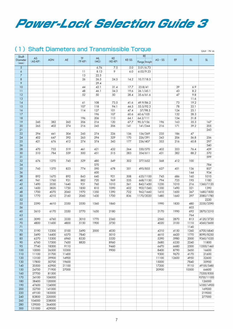
ShaftDiameter(mm)
AS(AS-KP) ADN AE TF
(TF-KP)ML
(MG)KE
(KE-KP)
REAS-SS EF EL SL
Flange Straight
5 006.76 0007.5 5.01/6.736 0011 008.13 0009.0 6.02/9.237 0013 0022.508 0026 0026.50 0024.5 10.7/18.59 0029.4010 0044 0042.10 0031.4 23.8/410 00039 00006.9 11 0048 0046.10 0034.3 26.1/45.1 00043 00008.2 12 0052 0050.00 0050.0 35.6/61.6 00047 00009.8 13 00011.614 0061 0108.00 0073.5 49.9/86.2 00073 00019.215 0107 0118.00 0094.1 53.5/92.3 00078 00022.116 0114 0127.00 0101.0 057/98.5 00124 00025.117 0196.00 0107.0 60.6/1050 00132 00028.318 0196 0206.00 0113.0 64.2/1110 00154 00031.819 000245 000382 00265 0206 0216.00 0120.0 90.3/1560 00196 00163 00035.3 000167 20 000265 000402 00274 0216 0245.00 0206.0 0141/2440 00216 00171 00039.2 000205 21 000243 22 000294 000441 00304 0245 0274.00 0226.0 0156/2690 00235 00186 00047.024 000402 000647 00392 0265 0294.00 0329.0 0226/3910 00343 00206 00056.8 000256 25 000421 000676 00412 0274 0374.00 0343.0 0236/4070 00353 00216 00060.8 000297 26 000340 28 000470 000755 00519 0461 0421.00 0432.0 0330/5700 00402 00353 00076.4 000459 30 000510 000784 00559 0500 0451.00 0515.0 0354/6110 00431 00382 00088.2 000570 31 000599 32 000676 001270 00745 0529 0480.00 0549.0 0377/6520 00568 00412 00100.034 0570.00 000784 35 000745 001370 00823 0774 0590.00 0678.0 0495/8550 00627 00451 00136.0 000857 36 0600.00 00144.0 000934 38 000892 001670 00892 0843 0640.00 0921.0 0635/1100 00745 00686 00160.0 00101040 000941 001760 00931 0882 0720.00 0969.0 0668/1150 00794 00725 00195.0 00118042 001490 003530 01640 0931 0760.00 1010.0 0842/1450 01230 01010 00216.0 1360/1120 45 001600 003820 01750 1850 0810.00 1090.0 0902/1560 01330 01490 00321.0 00139048 001700 004070 02060 1970 1350.00 1390.0 0962/1660 01410 01600 00367.0 1680/1850 50 001770 004210 02160 2060 1430.00 1700.0 1170/2020 01480 01660 00397.0 2080/1780 52 00222055 002390 004610 02350 2550 1560.00 1860.0 01990 01820 00480.0 2230/2590 56 00603.060 002610 006170 02550 2770 1650.00 2180.0 02170 01990 00692.0 2870/3310 63 00764.065 003090 006760 03330 3010 1770.00 2360.0 02560 02870 00813.0 4120/3720 70 004800 011600 04800 5150 1900.00 3750.0 04020 03100 01110.0 4560/5600 71 01140.075 005190 012300 05100 5490 2000.00 4030.0 04310 04150 01260.0 6700/6840 80 005490 014400 06570 7840 5010.0 04610 04420 01770.0 8090/8250 85 006370 015300 06960 8330 5320.0 05390 05980 02000.0 9360/102090 006760 017500 07450 8820 8960.0 05680 06330 02240.0 01180095 007740 018500 09110 9460.0 06470 06680 02500.0 13500/1460100 010000 026500 10300 9900.0 08400 08790 03450.0 016600110 011100 031700 11400 09300 09670 04170.0 021600120 013100 039900 14900 11100 12600 04950.0 032600130 017800 050700 19600 15000 07840.0 035900140 020500 062900 21100 17200 09110.0 49100/5480150 024700 071900 27000 20900 10500.0 064600160 027700 081500 75200/8300170 034100 106000 95700/111000180 038400 120000 126000190 047600 134000 141000/149000200 052700 141000 169000220 069100 183000 219000240 083800 220000 277000260 104000 238000280 129000 364000300 151000 429000
(1)Shaft Diameters and Transmissible Torque
Power-Lock Selection Guide 3
Unit:N・m
KE-SS
0005.0 0006.0
0014.2
0017.7 0019.6 0028.4
0041.60044.50047.40060.60064.10067.7
141
156170 177
264283
302
351
508535561602 722 836
8
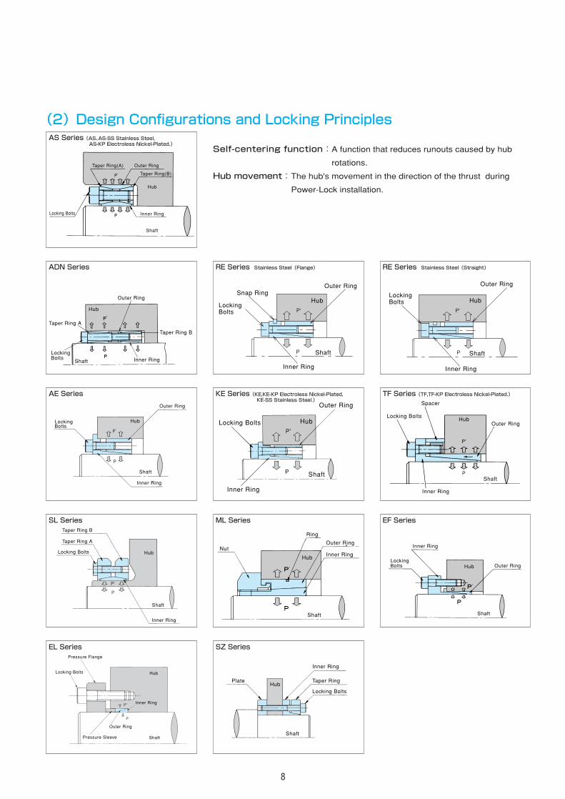
(2)Design Configurations and Locking Principles
Taper Ring(A)
Locking Bolts
Taper Ring(B)
Inner Ring
Shaft
Hub
Outer Ring
AS Series(AS、AS-SS Stainless Steel,AS-KP Electroless Nickel-Plated.)
Taper Ring A
Taper Ring B
Outer Ring
LockingBolts Inner RingShaft
Hub
ADN Series
Inner Ring
Shaft
HubLockingBolts
Outer Ring
AE Series
Taper Ring A
Taper Ring B
Locking Bolts
Inner Ring
Shaft
Hub
SL Series
Pressure Flange
Pressure Sleeve
Outer Ring
Locking Bolts
Inner Ring
Shaft
Hub
EL Series
Self-centering function:A function that reduces runouts caused by hub
rotations.
Hub movement:The hub's movement in the direction of the thrust during
Power-Lock installation.
Snap Ring
LockingBolts
P
P'
Hub
Inner Ring
Shaft
Outer Ring
RE Series Stainless Steel(Flange)
Inner Ring
Shaft
HubLocking Bolts
Outer Ring
KE Series(KE,KE-KP Electroless Nickel-Plated,KE-SS Stainless Steel.)
Nut
Ring
Outer Ring
Inner Ring
Shaft
Hub
ML Series
P
P'
Inner Ring
Shaft
Hub
Outer Ring
LockingBolts
RE Series Stainless Steel(Straight)
Inner Ring
Shaft
HubLocking Bolts
Spacer
Outer Ring
TF Series(TF,TF-KP Electroless Nickel-Plated.)
LockingBolts
Inner Ring
Outer Ring
Shaft
Hub
EF Series
Taper RingPlate
Locking Bolts
Inner Ring
Shaft
Hub
SZ Series
9
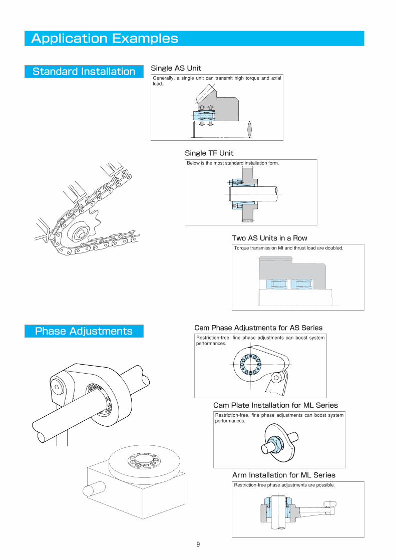
Application Examples
Standard Installation Single AS UnitGenerally, a single unit can transmit high torque and axialload.
Single TF UnitBelow is the most standard installation form.
Two AS Units in a RowTorque transmission Mt and thrust load are doubled.
Phase Adjustments Cam Phase Adjustments for AS SeriesRestriction-free, fine phase adjustments can boost systemperformances.
Cam Plate Installation for ML SeriesRestriction-free, fine phase adjustments can boost systemperformances.
Arm Installation for ML SeriesRestriction-free phase adjustments are possible.
10
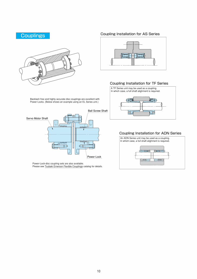
Couplings Coupling Installation for AS Series
Coupling Installation for TF SeriesA TF Series unit may be used as a coupling.In which case, a full shaft alighment is required.
Coupling Installation for ADN SeriesAn ADN Series unit may be used as a coupling.In which case, a full shaft alighment is required.
Servo Motor Shaft
Ball Screw Shaft
Power-Lock
Backlash free and highly accurate disc couplings are excellent withPower-Locks. (Below shows an example using an EL Series unit.)
Power-Lock-disc coupling sets are also available.Please see Tsubaki Emerson Flexible Couplings catalog for details.
11
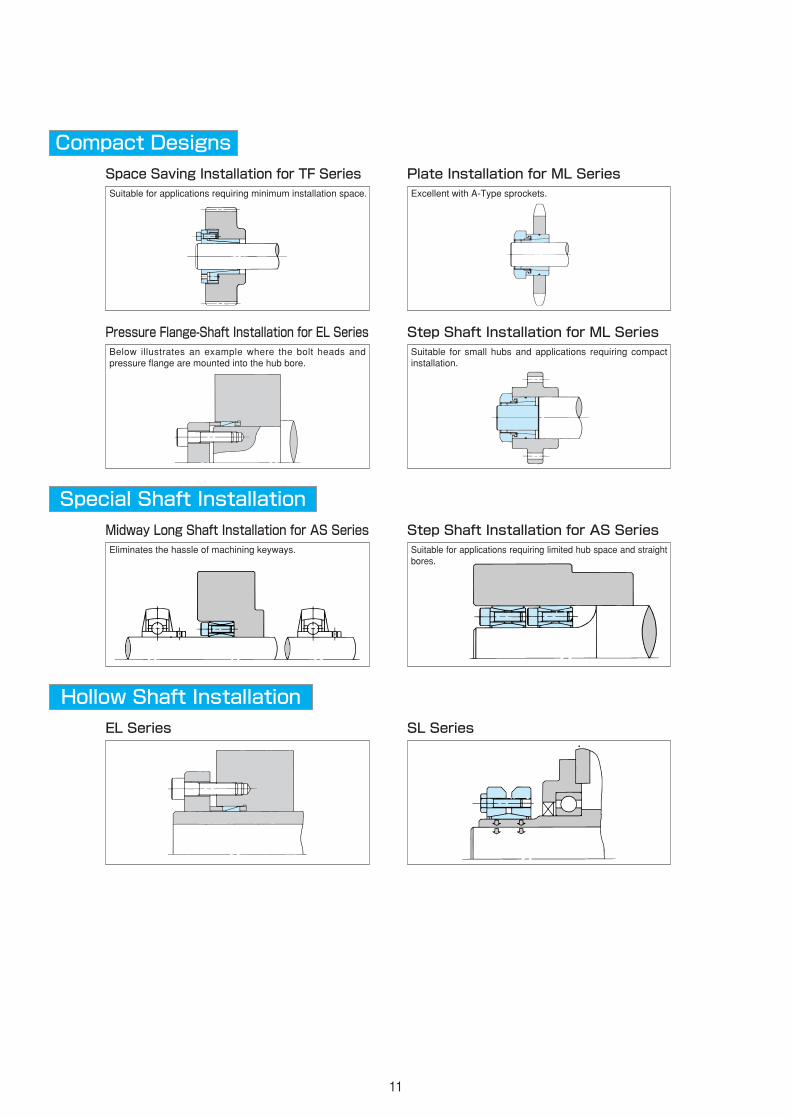
Compact Designs
Space Saving Installation for TF Series Suitable for applications requiring minimum installation space.
Plate Installation for ML SeriesExcellent with A-Type sprockets.
Special Shaft Installation
Midway Long Shaft Installation for AS SeriesEliminates the hassle of machining keyways.
Step Shaft Installation for AS SeriesSuitable for applications requiring limited hub space and straightbores.
Hollow Shaft Installation
EL Series SL Series
Pressure Flange-Shaft Installation for EL SeriesBelow illustrates an example where the bolt heads andpressure flange are mounted into the hub bore.
Step Shaft Installation for ML SeriesSuitable for small hubs and applications requiring compactinstallation.
AS
AS
AS
AS
AS
AS
AS
AS
AS
AS
12
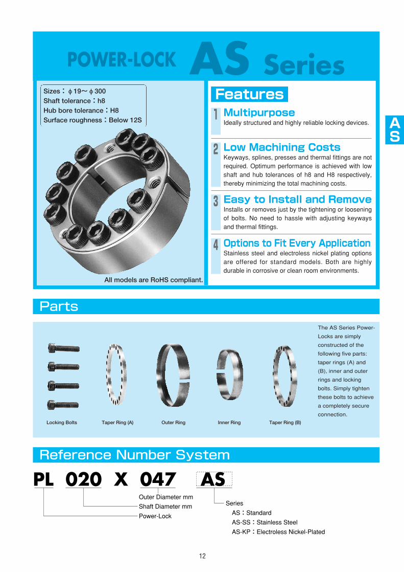
POWER-LOCK AS SeriesFeaturesSizes:φ19~φ300
Shaft tolerance:h8Hub bore tolerance:H8Surface roughness:Below 12S 1 Multipurpose
Ideally structured and highly reliable locking devices.
2 Low Machining CostsKeyways, splines, presses and thermal fittings are notrequired. Optimum performance is achieved with lowshaft and hub tolerances of h8 and H8 respectively,thereby minimizing the total machining costs.
3 Easy to Install and RemoveInstalls or removes just by the tightening or looseningof bolts. No need to hassle with adjusting keywaysand thermal fittings.
4 Options to Fit Every ApplicationStainless steel and electroless nickel plating optionsare offered for standard models. Both are highlydurable in corrosive or clean room environments.
Parts
Reference Number System
The AS Series Power-
Locks are simply
constructed of the
following five parts:
taper rings (A) and
(B), inner and outer
rings and locking
bolts. Simply tighten
these bolts to achieve
a completely secure
connection.
Locking Bolts Taper Ring (A) Outer Ring Inner Ring Taper Ring (B)
PL 020 X 047 AS
Power-Lock
Shaft Diameter mm
Outer Diameter mmSeries�
AS:Standard�
AS-SS:Stainless Steel�
AS-KP:Electroless Nickel-Plated
All models are RoHS compliant.

13
AS Series
■Standard
Model Numbers and Specifications
Lt
Tap Holes forRemoval
Dimensionsmm
L LtMt Pax P P' Quantity
N・m {kgf・m} kN {kgf} MPa {kgf/mm2} MPa {kgf/mm2}
PL 220 X 285 AS 56 51 72 69100 7050 628 64100 149 15.2 115 11.7 18
PL 240 X 305 AS 56 51 72 83800 8550 698 71200 152 15.5 120 12.2 20
PL 260 X 325 AS 56 51 72 104000 10600 803 81900 161 16.4 129 13.2 23
PL 280 X 355 AS 66 61 84 129000 13200 923 94200 144 14.7 114 11.6 22
PL 300 X 375 AS 66 61 84 151000 15400 1000 102000 147 15.0 118 12.0 24
Notes) 1. Stocked models are in bold.2. Mt indicates torque at 0 transmissible thrust, while Pax indicates transmissible thrust at 0 torque. If transmissible torque and thrust
apply simultaneously calculate and compare the combined value with the transmissible torque provided in the table.
PL 019 X 047 AS 20 26 245 25 26.5 2700 210 21.4 85 8.7 6
PL 020 X 047 AS 20 18
PL 022 X 047 AS 20 18 26 294 30 26.5 2700 181 18.5 85 8.7 6
PL 024 X 050 AS 20 18 26 402 41 33.3 3400 211 21.5 101 10.3 8
PL 025 X 050 AS 20 18 26 421 43 33.3 3400 203 20.7 101 10.3 8
PL 028 X 055 AS 20 18 26 470 48 33.3 3400 180 18.4 92 9.4 8
PL 030 X 055 AS 20 18 26 510 52 33.3 3400 169 17.2 92 9.4 8
PL 032 X 060 AS 20 18 26 676 69 42.1 4300 198 20.2 106 10.8 10
PL 035 X 060 AS 20 18 26 745 76 42.1 4300 181 18.5 106 10.8 10
PL 038 X 065 AS 20 18 26 892 91 47.0 4800 183 18.7 107 10.9 11
PL 040 X 065 AS 20 18 26 941 96 47.0 4800 174 17.8 107 10.9 11
PL 042 X 075 AS 24 21 32 1490 152 70.6 7200 214 21.8 121 12.3 9
PL 045 X 075 AS 24 21 32 1600 163 70.6 7200 200 20.4 121 12.3 9
PL 048 X 080 AS 24 21 32 1700 173 70.6 7200 188 19.2 113 11.5 9
PL 050 X 080 AS 24 21 32 1770 181 70.6 7200 180 18.4 113 11.5 9
PL 055 X 085 AS 24 21 32 2390 244 86.2 8800 201 20.5 130 13.3 11
PL 060 X 090 AS 24 21 32 2610 266 86.2 8800 184 18.8 123 12.5 11
PL 065 X 095 AS 24 21 32 3090 315 94.1 9600 184 18.8 126 12.9 12
PL 070 X 110 AS 28 25 38 4800 490 138 14100 210 21.4 133 13.6 11
PL 075 X 115 AS 28 25 38 5190 530 138 14100 196 20.0 127 13.0 11
PL 080 X 120 AS 28 25 38 5490 560 138 14100 184 18.8 123 12.5 11
PL 085 X 125 AS 28 25 38 6370 650 150 15300 189 19.3 128 13.1 12
PL 090 X 130 AS 28 25 38 6760 690 150 15300 178 18.2 123 12.6 12
PL 095 X 135 AS 28 25 38 7740 790 163 16600 183 18.7 129 13.2 13
PL 100 X 145 AS 33 29 45 10000 1020 201 20500 184 18.8 127 13.0 11
PL 110 X 155 AS 33 29 45 11100 1130 201 20500 168 17.1 120 12.2 11
PL 120 X 165 AS 33 29 45 13100 1340 220 22400 168 17.1 123 12.5 12
PL 130 X 180 AS 38 34 50 17800 1820 274 28000 166 16.9 120 12.2 15
PL 140 X 190 AS 38 34 50 20500 2090 292 29800 164 16.7 121 12.3 16
PL 150 X 200 AS 38 34 50 24700 2520 329 33600 172 17.5 129 13.2 18
PL 160 X 210 AS 38 34 50 27700 2830 347 35400 170 17.3 129 13.2 19
PL 170 X 225 AS 44 40 58 34100 3480 402 41000 157 16.0 119 12.1 16
PL 180 X 235 AS 44 40 58 38400 3920 426 43500 158 16.1 121 12.3 17
PL 190 X 250 AS 52 48 66 47600 4860 502 51200 147 15.0 112 11.4 20
PL 200 X 260 AS 52 48 66 52700 5380 527 53800 146 14.9 113 11.5 21
TransmissibleTorque
TransmissibleThrust
Shaft ContactPressure
Hub ContactPressure Locking Bolts Mass
RSize Tightening Torque
MAN・m {kgf・m} kg
18 M6×18 16.7 1.7 0.20
26 265 27 26.5 2700 199 20.3 85 8.7 6 M6×18 16.7 1.7 0.20
M6×18 16.7 1.7 0.19
M6×18 16.7 1.7 0.22
M6×18 16.7 1.7 0.22
M6×18 16.7 1.7 0.25
M6×18 16.7 1.7 0.24
M6×18 16.7 1.7 0.27
M6×18 16.7 1.7 0.27
M6×18 16.7 1.7 0.30
M6×18 16.7 1.7 0.30
M8×22 40.2 4.1 0.51
M8×22 40.2 4.1 0.51
M8×22 40.2 4.1 0.55
M8×22 40.2 4.1 0.55
M8×22 40.2 4.1 0.60
M8×22 40.2 4.1 0.64
M8×22 40.2 4.1 0.69
M10×25 81.3 8.3 1.21
M10×25 81.3 8.3 1.27
M10×25 81.3 8.3 1.33
M10×25 81.3 8.3 1.41
M10×25 81.3 8.3 1.47
M10×25 81.3 8.3 1.54
M12×30 142 14.5 2.09
M12×30 142 14.5 2.25
M12×30 142 14.5 2.42
M12×35 142 14.5 3.38
M12×35 142 14.5 3.59
M12×35 142 14.5 3.82
M12×35 142 14.5 4.03
M14×40 225 23.0 5.49
M14×40 225 23.0 5.78
M14×45 225 23.0 7.89
M14×45 225 23.0 8.26
M16×50 348 35.5 10.6
M16×50 348 35.5 11.5
M16×50 348 35.5 12.4
M18×60 475 48.5 18.7
M18×60 475 48.5 19.9
mm
Model No.d X D
Shaft Diameter XOuter Diameter
P and P' represent the average contact pressure applied to theshaft and hub respectively. These values may vary from -20%to +40%, depending on the amount of friction applied to thebolts. Transmissible torque Mt and transmissible thrust Pax arecalculated from the minimum allowable contact pressure.
Taper Ring(A)
LockingBolts
Taper Ring(B)
Inner Ring
Shaft
Hub
Outer Ring
mm
AS
AS
AS
AS
AS
AS
AS
AS
AS
AS
14
AS Series
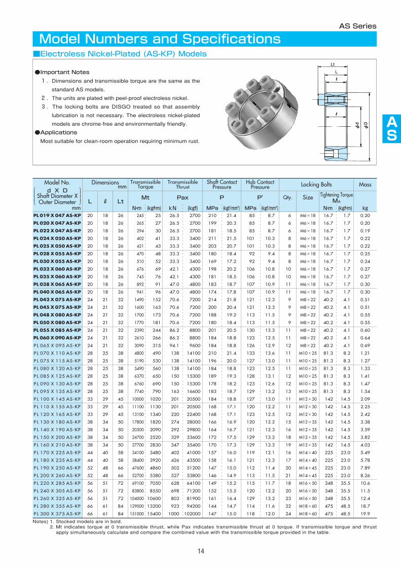
■Electroless Nickel-Plated (AS-KP) Models
Model Numbers and Specifications
L LtMt Pax P P' Qty.
N・m {kgf・m} kN {kgf} MPa {kgf/mm2} MPa {kgf/mm2}
P L 220 X 285 AS-KP 56 51 72 69100 7050 628 64100 149 15.2 115 11.7 18
P L 240 X 305 AS-KP 56 51 72 83800 8550 698 71200 152 15.5 120 12.2 20
P L 260 X 325 AS-KP 56 51 72 104000 10600 803 81900 161 16.4 129 13.2 23
P L 280 X 355 AS-KP 66 61 84 129000 13200 923 94200 144 14.7 114 11.6 22
P L 300 X 375 AS-KP 66 61 84 151000 15400 1000 102000 147 15.0 118 12.0 24
Notes) 1. Stocked models are in bold.2. Mt indicates torque at 0 transmissible thrust, while Pax indicates transmissible thrust at 0 torque. If transmissible torque and thrust
apply simultaneously calculate and compare the combined value with the transmissible torque provided in the table.
PL 019 X 047 AS-KP 20 26 245 25 26.5 2700 210 21.4 85 8.7 6
PL 020 X 047 AS-KP 20 18
PL 022 X 047 AS-KP 20 18 26 294 30 26.5 2700 181 18.5 85 8.7 6
PL 024 X 050 AS-KP 20 18 26 402 41 33.3 3400 211 21.5 101 10.3 8
PL 025 X 050 AS-KP 20 18 26 421 43 33.3 3400 203 20.7 101 10.3 8
PL 028 X 055 AS-KP 20 18 26 470 48 33.3 3400 180 18.4 92 9.4 8
PL 030 X 055 AS-KP 20 18 26 510 52 33.3 3400 169 17.2 92 9.4 8
PL 032 X 060 AS-KP 20 18 26 676 69 42.1 4300 198 20.2 106 10.8 10
PL 035 X 060 AS-KP 20 18 26 745 76 42.1 4300 181 18.5 106 10.8 10
PL 038 X 065 AS-KP 20 18 26 892 91 47.0 4800 183 18.7 107 10.9 11
PL 040 X 065 AS-KP 20 18 26 941 96 47.0 4800 174 17.8 107 10.9 11
PL 042 X 075 AS-KP 24 21 32 1490 152 70.6 7200 214 21.8 121 12.3 9
PL 045 X 075 AS-KP 24 21 32 1600 163 70.6 7200 200 20.4 121 12.3 9
PL 048 X 080 AS-KP 24 21 32 1700 173 70.6 7200 188 19.2 113 11.5 9
PL 050 X 080 AS-KP 24 21 32 1770 181 70.6 7200 180 18.4 113 11.5 9
PL 055 X 085 AS-KP 24 21 32 2390 244 86.2 8800 201 20.5 130 13.3 11
PL 060 X 090 AS-KP 24 21 32 2610 266 86.2 8800 184 18.8 123 12.5 11
P L 065 X 095 AS-KP 24 21 32 3090 315 94.1 9600 184 18.8 126 12.9 12
P L 070 X 110 AS-KP 28 25 38 4800 490 138 14100 210 21.4 133 13.6 11
P L 075 X 115 AS-KP 28 25 38 5190 530 138 14100 196 20.0 127 13.0 11
P L 080 X 120 AS-KP 28 25 38 5490 560 138 14100 184 18.8 123 12.5 11
P L 085 X 125 AS-KP 28 25 38 6370 650 150 15300 189 19.3 128 13.1 12
P L 090 X 130 AS-KP 28 25 38 6760 690 150 15300 178 18.2 123 12.6 12
P L 095 X 135 AS-KP 28 25 38 7740 790 163 16600 183 18.7 129 13.2 13
P L 100 X 145 AS-KP 33 29 45 10000 1020 201 20500 184 18.8 127 13.0 11
P L 110 X 155 AS-KP 33 29 45 11100 1130 201 20500 168 17.1 120 12.2 11
P L 120 X 165 AS-KP 33 29 45 13100 1340 220 22400 168 17.1 123 12.5 12
P L 130 X 180 AS-KP 38 34 50 17800 1820 274 28000 166 16.9 120 12.2 15
P L 140 X 190 AS-KP 38 34 50 20500 2090 292 29800 164 16.7 121 12.3 16
P L 150 X 200 AS-KP 38 34 50 24700 2520 329 33600 172 17.5 129 13.2 18
P L 160 X 210 AS-KP 38 34 50 27700 2830 347 35400 170 17.3 129 13.2 19
P L 170 X 225 AS-KP 44 40 58 34100 3480 402 41000 157 16.0 119 12.1 16
P L 180 X 235 AS-KP 44 40 58 38400 3920 426 43500 158 16.1 121 12.3 17
P L 190 X 250 AS-KP 52 48 66 47600 4860 502 51200 147 15.0 112 11.4 20
P L 200 X 260 AS-KP 52 48 66 52700 5380 527 53800 146 14.9 113 11.5 21
TransmissibleTorque
TransmissibleThrust
Shaft ContactPressure
Hub ContactPressure Locking Bolts Mass
RSize Tightening Torque
MAN・m {kgf・m} kg
18 M6×18 16.7 1.7 0.20
26 265 27 26.5 2700 199 20.3 85 8.7 6 M6×18 16.7 1.7 0.20
M6×18 16.7 1.7 0.19
M6×18 16.7 1.7 0.22
M6×18 16.7 1.7 0.22
M6×18 16.7 1.7 0.25
M6×18 16.7 1.7 0.24
M6×18 16.7 1.7 0.27
M6×18 16.7 1.7 0.27
M6×18 16.7 1.7 0.30
M6×18 16.7 1.7 0.30
M8×22 40.2 4.1 0.51
M8×22 40.2 4.1 0.51
M8×22 40.2 4.1 0.55
M8×22 40.2 4.1 0.55
M8×22 40.2 4.1 0.60
M8×22 40.2 4.1 0.64
M8×22 40.2 4.1 0.69
M10×25 81.3 8.3 1.21
M10×25 81.3 8.3 1.27
M10×25 81.3 8.3 1.33
M10×25 81.3 8.3 1.41
M10×25 81.3 8.3 1.47
M10×25 81.3 8.3 1.54
M12×30 142 14.5 2.09
M12×30 142 14.5 2.25
M12×30 142 14.5 2.42
M12×35 142 14.5 3.38
M12×35 142 14.5 3.59
M12×35 142 14.5 3.82
M12×35 142 14.5 4.03
M14×40 225 23.0 5.49
M14×40 225 23.0 5.78
M14×45 225 23.0 7.89
M14×45 225 23.0 8.26
M16×50 348 35.5 10.6
M16×50 348 35.5 11.5
M16×50 348 35.5 12.4
M18×60 475 48.5 18.7
M18×60 475 48.5 19.9
●Important Notes
1.Dimensions and transmissible torque are the same as the
standard AS models.
2.The units are plated with peel-proof electroless nickel.
3.The locking bolts are DISGO treated so that assembly
lubrication is not necessary. The electroless nickel-plated
models are chrome-free and environmentally friendly.
●Applications
Most suitable for clean-room operation requiring minimum rust.
Lt
Model No.d X D
Shaft Diameter XOuter Diameter
mm
Dimensions
Model Numbers and SpecificationsAS Series
15
Dimensionsmm
TransmissibleTorque
TransmissibleThrust
Shaft ContactPressure
Hub ContactPressure Locking Bolts
L R LtMt Pax P P' Qty.
N・m {kgf・m} kN {kgf} MPa {kgf/mm2} MPa {kgf/mm2}
PL 110 X 155 AS-SS 33 29 45 9300 950 170 17300 148 15.1 105 10.7 11
PL 120 X 165 AS-SS 33 29 45 11100 1130 185 18900 148 15.1 108 11.0 12
PL 130 X 180 AS-SS 38 34 50 15000 1530 231 23600 146 14.9 106 10.8 15
PL 140 X 190 AS-SS 38 34 50 17200 1760 247 25200 144 14.7 107 10.9 16
PL 150 X 200 AS-SS 38 34 50 20900 2130 278 28400 152 15.5 114 11.6 18
Notes) 1. Stocked models are in bold.2. Mt indicates torque at 0 transmissible thrust, while Pax indicates transmissible thrust at 0 torque. If transmissible torque and thrust
apply simultaneously calculate and compare the combined value with the transmissible torque provided in the table.
Mass
Size Tightening TorqueMA
N・m {kgf・m} kg
M12×30 118 12.0 2.25
M12×30 118 12.0 2.42
M12×35 118 12.0 3.38
M12×35 118 12.0 3.59
M12×35 118 12.0 3.82
PL 019 X 047 AS-SS 20 18 26 196 20 21.6 2200 175 17.9 72 7.3 6 M6×18 13.7 1.4 0.20
PL 020 X 047 AS-SS 20 18 26 216 22 21.6 2200 167 17.0 72 7.3 6 M6×18 13.7 1.4 0.20
PL 022 X 047 AS-SS 20 18 26 235 24 21.6 2200 152 15.5 72 7.3 6 M6×18 13.7 1.4 0.19
PL 024 X 050 AS-SS 20 18 26 343 35 28.4 2900 186 19.0 89 9.1 8 M6×18 13.7 1.4 0.22
PL 025 X 050 AS-SS 20 18 26 353 36 28.4 2900 178 18.2 89 9.1 8 M6×18 13.7 1.4 0.22
PL 028 X 055 AS-SS 20 18 26 402 41 28.4 2900 160 16.3 81 8.3 8 M6×18 13.7 1.4 0.25
PL 030 X 055 AS-SS 20 18 26 431 44 28.4 2900 149 15.2 81 8.3 8 M6×18 13.7 1.4 0.24
PL 032 X 060 AS-SS 20 18 26 568 58 35.3 3600 174 17.8 93 9.5 10 M6×18 13.7 1.4 0.27
PL 035 X 060 AS-SS 20 18 26 627 64 35.3 3600 160 16.3 93 9.5 10 M6×18 13.7 1.4 0.27
PL 038 X 065 AS-SS 20 18 26 745 76 39.2 4000 157 16.0 95 9.7 11 M6×18 13.7 1.4 0.30
PL 040 X 065 AS-SS 20 18 26 794 81 39.2 4000 149 15.2 95 9.7 11 M6×18 13.7 1.4 0.30
PL 042 X 075 AS-SS 24 21 32 1230 126 58.8 6000 187 19.1 105 10.7 9 M8×22 33.3 3.4 0.51
PL 045 X 075 AS-SS 24 21 32 1330 136 58.8 6000 174 17.8 105 10.7 9 M8×22 33.3 3.4 0.51
PL 048 X 080 AS-SS 24 21 32 1410 144 58.8 6000 164 16.7 98 10.0 9 M8×22 33.3 3.4 0.55
PL 050 X 080 AS-SS 24 21 32 1480 151 58.8 6000 157 16.0 98 10.0 9 M8×22 33.3 3.4 0.55
PL 055 X 085 AS-SS 24 21 32 1990 203 71.5 7300 174 17.8 113 11.5 11 M8×22 33.3 3.4 0.60
PL 060 X 090 AS-SS 24 21 32 2170 221 71.5 7300 160 16.3 107 10.9 11 M8×22 33.3 3.4 0.64
PL 065 X 095 AS-SS 24 21 32 2560 261 78.4 8000 161 16.4 110 11.2 12 M8×22 33.3 3.4 0.69
PL 070 X 110 AS-SS 28 25 38 4020 410 117 11900 185 18.9 119 12.1 11 M10×25 67.6 6.9 1.21
PL 075 X 115 AS-SS 28 25 38 4310 440 117 11900 173 17.7 113 11.5 11 M10×25 67.6 6.9 1.27
PL 080 X 120 AS-SS 28 25 38 4610 470 117 11900 163 16.6 109 11.1 11 M10×25 67.6 6.9 1.33
PL 085 X 125 AS-SS 28 25 38 5390 550 127 13000 167 17.0 114 11.6 12 M10×25 67.6 6.9 1.41
PL 090 X 130 AS-SS 28 25 38 5680 580 127 13000 158 16.1 109 11.1 12 M10×25 67.6 6.9 1.47
PL 095 X 135 AS-SS 28 25 38 6470 660 138 14100 162 16.5 114 11.6 13 M10×25 67.6 6.9 1.54
PL 100 X 145 AS-SS 33 29 45 8400 860 170 17300 162 16.5 113 11.5 11 M12×30 118 12.0 2.09
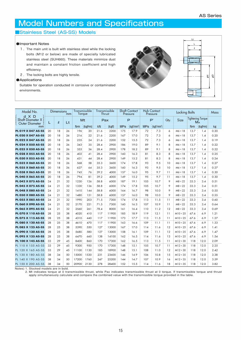
■Stainless Steel (AS-SS) Models
Lt
●Important Notes
1.The main unit is built with stainless steel while the locking
bolts (M12 or below) are made of specially lubricated
stainless steel (SUH660). These materials minimize dust
and maintain a constant friction coefficient and high
efficiency.
2.The locking bolts are highly tensile.
●Applications
Suitable for operation conducted in corrosive or contaminated
environments.
mm
Model No.d X D
Shaft Diameter XOuter Diameter
AS
AS
AS
AS
AS
AS
AS
AS
AS
AS
16
Model Numbers and SpecificationsAS Series
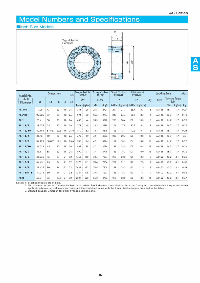
■Inch Size ModelsLt
Tap Holes forRemoval
Notes) 1. Stocked models are in bold.2. Mt indicates torque at 0 transmissible thrust, while Pax indicates transmissible thrust at 0 torque. If transmissible torque and thrust
apply simultaneously calculate and compare the combined value with the transmissible torque provided in the table.3. Consult Tsubaki Emerson for other available dimensions.
Model No.Shaft
Diameter
Dimensions mm
d LtMt Pax P P' Qty.
N・m {kgf・m} kN {kgf} MPa {kgf/mm2} MPa {kgf/mm2}
PL 3/4 19.050 26.0 0254 026 26.5 2704 209 21.3 085.4 08.7 06
PL 7/8 22.225 18
PL 1 25.400 18 26.0 0430 044 33.3 3398 200 20.4 101.0 10.3 08
PL 1 1/8 28.575 18 26.0 0479 049 33.3 3398 176 17.9 092.3 09.4 08
PL 1 3/16 30.163 18 26.8 0510 052 33.3 3398 168 17.1 092.3 09.4 08
PL 1 1/4 31.750 18 26.0 0675 069 42.1 4296 200 20.4 106.0 10.8 10
PL 1 3/8 34.925 18 25.6 0745 076 42.1 4296 182 18.5 106.0 10.8 10
PL 1 7/16 36.513 18 26.0 0862 088 47.0 4796 191 19.5 107.0 10.9 11
PL 1 1/2 38.100 18 26.0 0890 091 47.0 4796 183 18.7 107.0 10.9 11
PL 1 5/8 41.275 21 32.0 1468 150 70.6 7204 218 22.2 121.0 12.3 09
PL 1 3/4 44.450 21 32.0 1575 161 70.6 7204 207 21.1 121.0 12.3 09
PL 1 7/8 47.625 21 32.0 1683 172 70.6 7204 189 19.3 113.0 11.5 09
PL 1 15/16 49.213 21 32.0 1741 178 70.6 7204 183 18.7 113.0 11.5 09
PL 2 50.800 21 32.0 2201 225 86.2 8796 218 22.2 130.0 13.3 11
TransmissibleTorque
TransmissibleThrust
Shaft ContactPressure
Hub ContactPressure Locking Bolts Mass
RSize Tightening Torque
MAN・m {kgf・m} kg
18 M6×18 16.7 1.7 0.21
26.0 0294 030 26.5 2704 249 25.4 085.4 08.7 06 M6×18 16.7 1.7 0.18
M6×18 16.7 1.7 0.22
M6×18 16.7 1.7 0.25
M6×18 16.7 1.7 0.24
M6×18 16.7 1.7 0.3
M6×18 16.7 1.7 0.27
M6×18 16.7 1.7 0.34
M6×18 16.7 1.7 0.32
M8×22 40.2 4.1 0.56
M8×22 40.2 4.1 0.56
M8×22 40.2 4.1 0.59
M8×22 40.2 4.1 0.56
M8×22 40.2 4.1 0.67
D L
47.000 20.0
47.000 20.0
50.000 20.0
55.000 20.0
54.837 20.8
60.000 20.0
60.075 19.6
65.000 20.0
65.000 20.0
75.000 24.0
75.000 24.0
80.000 24.0
80.000 24.0
85.000 24.0
17
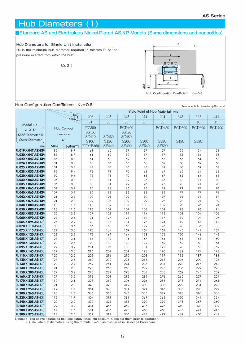
Hub Diameters (1)AS Series
■Standard AS and Electroless Nickel-Plated AS-KP Models (Same dimensions and capacities)
Hub Contact
Pressure
P'
FCD700
PL 220 X 285 AS(-KP) 115 11.7 334 PL 240 X 305 AS(-KP) 120 12.2 360 PL 260 X 325 AS(-KP) 129 13.2 389 PL 280 X 355 AS(-KP) 114 11.6 415
44145
MPa {kgf/mm2}
206 225 245 274 294 343 39221 23 25 28 30 35 40
FC350SS400SC410S10C
FCMB360
SC450S15CSF440
FCD400SS490SC480S20CSF490
S30CSF540
FCD450
S35CSF590
FCD500
S45C
FCD600
S55C
404 391 381 369 362 350 341 439 425 413 399 392 378 367 484 466 452 435 426 410 398 501 486 473 458 450 435 424
MPakgf/mm 2
PL 300 X 375 AS(-KP) 118 12.0 537 519 505 488 479 462 450 441
PL 019 X 047 AS(-KP) 85 8.7 61 60 59 57 57 55 54 53PL 020 X 047 AS(-KP) 85 8.7 61 60 59 57 57 55 54 53PL 022 X 047 AS(-KP) 85 8.7 61 60 59 57 57 55 54 53PL 024 X 050 AS(-KP) 101 10.3 68 66 65 63 62 60 59 58PL 025 X 050 AS(-KP) 101 10.3 68 66 65 63 62 60 59 58PL 028 X 055 AS(-KP) 92 9.4 73 71 70 68 67 65 64 63PL 030 X 055 AS(-KP) 92 9.4 73 71 70 68 67 65 64 63PL 032 X 060 AS(-KP) 106 10.8 83 81 79 76 75 73 71 70PL 035 X 060 AS(-KP) 106 10.8 83 81 79 76 75 73 71 70PL 038 X 065 AS(-KP) 107 10.9 90 88 85 83 82 79 77 76PL 040 X 065 AS(-KP) 107 10.9 90 88 85 83 82 79 77 76PL 042 X 075 AS(-KP) 121 12.3 109 105 102 99 97 93 91 89PL 045 X 075 AS(-KP) 121 12.3 109 105 102 99 97 93 91 89PL 048 X 080 AS(-KP) 113 11.5 113 109 107 103 102 98 96 94PL 050 X 080 AS(-KP) 113 11.5 113 109 107 103 102 98 96 94PL 055 X 085 AS(-KP) 130 13.3 127 123 119 114 112 108 104 102 PL 060 X 090 AS(-KP) 123 12.5 131 127 123 119 117 112 109 107 PL 065 X 095 AS(-KP) 126 12.9 140 135 131 127 124 119 116 113 PL 070 X 110 AS(-KP) 133 13.6 166 160 155 149 146 140 136 133 PL 075 X 115 AS(-KP) 127 13.0 170 164 159 154 151 145 141 137 PL 080 X 120 AS(-KP) 123 12.5 175 169 164 158 155 150 146 142 PL 085 X 125 AS(-KP) 128 13.1 186 179 174 167 164 158 153 150 PL 090 X 130 AS(-KP) 123 12.6 190 183 178 172 169 162 158 154 PL 095 X 135 AS(-KP) 129 13.2 201 194 188 181 177 170 165 162 PL 100 X 145 AS(-KP) 127 13.0 215 207 201 193 190 182 177 173 PL 110 X 155 AS(-KP) 120 12.2 223 216 210 203 199 192 187 183 PL 120 X 165 AS(-KP) 123 12.5 240 232 225 218 213 206 200 196 PL 130 X 180 AS(-KP) 120 12.2 259 251 244 236 231 223 217 213 PL 140 X 190 AS(-KP) 121 12.3 275 265 258 249 245 236 229 225 PL 150 X 200 AS(-KP) 129 13.2 298 287 278 268 263 252 245 239 PL 160 X 210 AS(-KP) 129 13.2 313 301 292 281 276 265 257 251 PL 170 X 225 AS(-KP) 119 12.1 323 312 304 294 288 278 271 265 PL 180 X 235 AS(-KP) 121 12.3 340 328 319 308 303 292 284 278 PL 190 X 250 AS(-KP) 112 11.4 351 340 331 321 316 305 298 292 PL 200 X 260 AS(-KP) 113 11.5 366 355 346 335 329 318 310 304
Notes) 1. The above figures do not take safety rates into account. Consider them prior to operation.2. Calculate hub diameters using the formula K3=0.6 as discussed in Selection Procedure.
Lt
Model No.
d X DShaft Diameter XOuter Diameter
Hub Diameters for Single Unit Installation
DN is the minimum hub diameter required to tolerate P' or the
pressure exerted from within the hub.
B≧2r
Hub Configuration Coefficient K3=0.6
Hub Configuration Coefficient K3=0.6
mm
Minimum hub diameterφDN(mm)
Yield Point of Hub Material σ0.2
AS
AS
AS
AS
AS
AS
AS
AS
AS
AS
18
Hub Contact
Pressure
P'
FCD700
PL 220 X 285 AS(-KP) 115 11.7 352 PL 240 X 305 AS(-KP) 120 12.2 281 PL 260 X 325 AS(-KP) 129 13.2 413 PL 280 X 355 AS(-KP) 114 11.6 438
44145
MPa {kgf/mm2}
206 225 245 274 294 343 39221 23 25 28 30 35 40
FC350SS400SC410S10C
FCMB360
SC450S15CSF440
FCD400SS490SC480S20CSF490
S30CSF540
FCD450
S35CSF590
FCD500
S45C
FCD600
S55C
461 439 423 404 394 375 362 505 480 461 439 428 407 392 566 534 510 484 470 444 426 571 545 525 501 489 466 450
PL 300 X 375 AS(-KP) 118 12.0 615 585 563 537 523 497 479 466
PL 019 X 047 AS(-KP) 85 8.7 67 65 63 61 60 58 57 55PL 020 X 047 AS(-KP) 85 8.7 67 65 63 61 60 58 57 55PL 022 X 047 AS(-KP) 85 8.7 67 65 63 61 60 58 57 55PL 024 X 050 AS(-KP) 101 10.3 76 73 71 68 67 64 62 61PL 025 X 050 AS(-KP) 101 10.3 76 73 71 68 67 64 62 61PL 028 X 055 AS(-KP) 92 9.4 80 78 76 73 72 69 67 66PL 030 X 055 AS(-KP) 92 9.4 80 78 76 73 72 69 67 66PL 032 X 060 AS(-KP) 106 10.8 93 90 86 83 81 78 75 73PL 035 X 060 AS(-KP) 106 10.8 93 90 86 83 81 78 75 73PL 038 X 065 AS(-KP) 107 10.9 102 97 94 90 88 84 82 80PL 040 X 065 AS(-KP) 107 10.9 102 97 94 90 88 84 82 80PL 042 X 075 AS(-KP) 121 12.3 125 119 114 109 106 101 97 94PL 045 X 075 AS(-KP) 121 12.3 125 119 114 109 106 101 97 94PL 048 X 080 AS(-KP) 113 11.5 128 123 118 113 110 105 102 99PL 050 X 080 AS(-KP) 113 11.5 128 123 118 113 110 105 102 99PL 055 X 085 AS(-KP) 130 13.3 149 141 134 127 124 117 112 109 PL 060 X 090 AS(-KP) 123 12.5 152 144 138 131 128 121 117 113 PL 065 X 095 AS(-KP) 126 12.9 163 154 148 140 136 129 124 120 PL 070 X 110 AS(-KP) 133 13.6 196 184 176 166 161 152 146 141 PL 075 X 115 AS(-KP) 127 13.0 198 188 180 170 166 157 151 146 PL 080 X 120 AS(-KP) 123 12.5 202 192 184 175 170 161 155 151 PL 085 X 125 AS(-KP) 128 13.1 217 205 196 186 180 171 164 159 PL 090 X 130 AS(-KP) 123 12.6 220 208 200 190 185 175 169 164 PL 095 X 135 AS(-KP) 129 13.2 235 222 212 201 195 185 177 172 PL 100 X 145 AS(-KP) 127 13.0 250 237 226 215 209 197 190 184 PL 110 X 155 AS(-KP) 120 12.2 257 244 235 223 218 207 199 194 PL 120 X 165 AS(-KP) 123 12.5 277 263 252 240 234 222 213 207 PL 130 X 180 AS(-KP) 120 12.2 298 284 272 259 253 240 231 225 PL 140 X 190 AS(-KP) 121 12.3 316 301 288 275 268 254 245 238 PL 150 X 200 AS(-KP) 129 13.2 348 329 314 298 28 274 263 254 PL 160 X 210 AS(-KP) 129 13.2 366 345 330 313 304 287 276 267 PL 170 X 225 AS(-KP) 119 12.1 371 353 339 323 315 299 288 280 PL 180 X 235 AS(-KP) 121 12.3 391 372 357 340 331 314 303 294 PL 190 X 250 AS(-KP) 112 11.4 399 381 367 351 343 327 316 307 PL 200 X 260 AS(-KP) 113 11.5 416 398 383 366 357 341 329 320
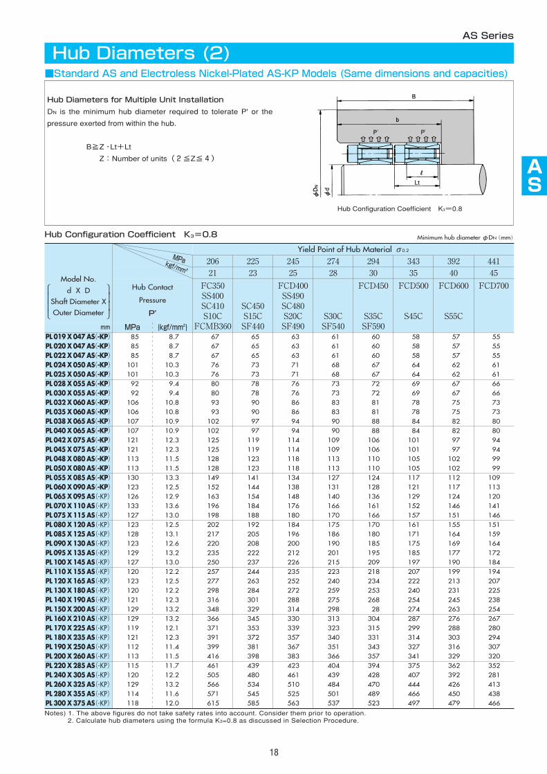
Notes) 1. The above figures do not take safety rates into account. Consider them prior to operation.2. Calculate hub diameters using the formula K3=0.8 as discussed in Selection Procedure.
■Standard AS and Electroless Nickel-Plated AS-KP Models (Same dimensions and capacities)
Lt
Hub Diameters for Multiple Unit Installation
DN is the minimum hub diameter required to tolerate P' or the
pressure exerted from within the hub.
B≧Z・Lt+Lt
Z:Number of units(2≦Z≦4)
Hub Diameters (2)AS Series
MPakgf/mm 2
Model No.
d X DShaft Diameter XOuter Diameter
Hub Configuration Coefficient K3=0.8
Hub Configuration Coefficient K3=0.8
mm
Minimum hub diameterφDN(mm)
Yield Point of Hub Material σ0.2
176 206 225 245 274 294 34318 21 23 25 28 30 35
Hub Contact
Pressure
P'
FC300SS330SC360
SUS405
FC350SS400SC410S10CSUS304
SC450S15CSF440
FCD400SS490SC480S20CSF490
S30CSF540
FCD450
S35CSF590
FCD500
S45Cmm MPa {kgf/mm2}
PL 019 X 047 AS-SS 72 7.3 61 59 57 57 56 55 54
PL 020 X 047 AS-SS 72 7.3 61 59 57 57 56 55 54
PL 022 X 047 AS-SS 72 7.3 61 59 57 57 56 55 54
PL 024 X 050 AS-SS 89 9.1 69 66 64 63 61 61 59
PL 025 X 050 AS-SS 89 9.1 69 66 64 63 61 61 59
PL 028 X 055 AS-SS 81 8.3 74 71 69 68 66 66 64
PL 030 X 055 AS-SS 81 8.3 74 71 69 68 66 66 64
PL 032 X 060 AS-SS 93 9.5 84 80 78 76 74 73 71
PL 035 X 060 AS-SS 93 9.5 84 80 78 76 74 73 71
PL 038 X 065 AS-SS 95 9.7 91 87 85 83 81 80 77
PL 040 X 065 AS-SS 95 9.7 91 87 85 83 81 80 77
PL 042 X 075 AS-SS 105 10.7 109 103 100 98 95 94 91
PL 045 X 075 AS-SS 105 10.7 109 103 100 98 95 94 91
PL 048 X 080 AS-SS 98 10.0 114 108 105 103 100 98 96
PL 050 X 080 AS-SS 98 10.0 114 108 105 103 100 98 96
PL 055 X 085 AS-SS 113 11.5 128 120 116 113 110 108 104
PL 060 X 090 AS-SS 107 10.9 132 125 121 118 115 113 109
PL 065 X 095 AS-SS 110 11.2 141 133 129 126 122 120 116
PL 070 X 110 AS-SS 119 12.1 169 158 153 149 144 141 136
PL 075 X 115 AS-SS 113 11.5 173 162 157 153 148 146 141
PL 080 X 120 AS-SS 109 11.1 177 167 162 158 153 151 146
PL 085 X 125 AS-SS 114 11.6 188 177 171 167 162 159 153
PL 090 X 130 AS-SS 109 11.1 192 181 176 171 166 163 158
PL 095 X 135 AS-SS 114 11.6 203 191 185 180 175 171 166
PL 100 X 145 AS-SS 113 11.5 218 204 198 193 187 184 178
PL 110 X 155 AS-SS 105 10.7 226 213 207 202 196 193 187
PL 120 X 165 AS-SS 108 11.0 243 229 222 217 210 207 200
PL 130 X 180 AS-SS 106 10.8 263 248 241 235 228 225 218
PL 140 X 190 AS-SS 107 10.9 279 263 255 249 242 238 230
PL 150 X 200 AS-SS 114 11.6 301 283 274 267 258 254 245
392 44140 45
FCD600
S55C
FCD700
53 52
53 52
53 52
58 57
58 57
63 62
63 62
70 69
70 69
76 75
76 75
89 87
89 87
94 92
94 92
102 100
107 105
113 111
133 130
137 135
142 140
150 147
154 151
161 158
173 170
183 179
195 192
212 209
225 220
239 234
Yield Point of Hub Material σ0.2
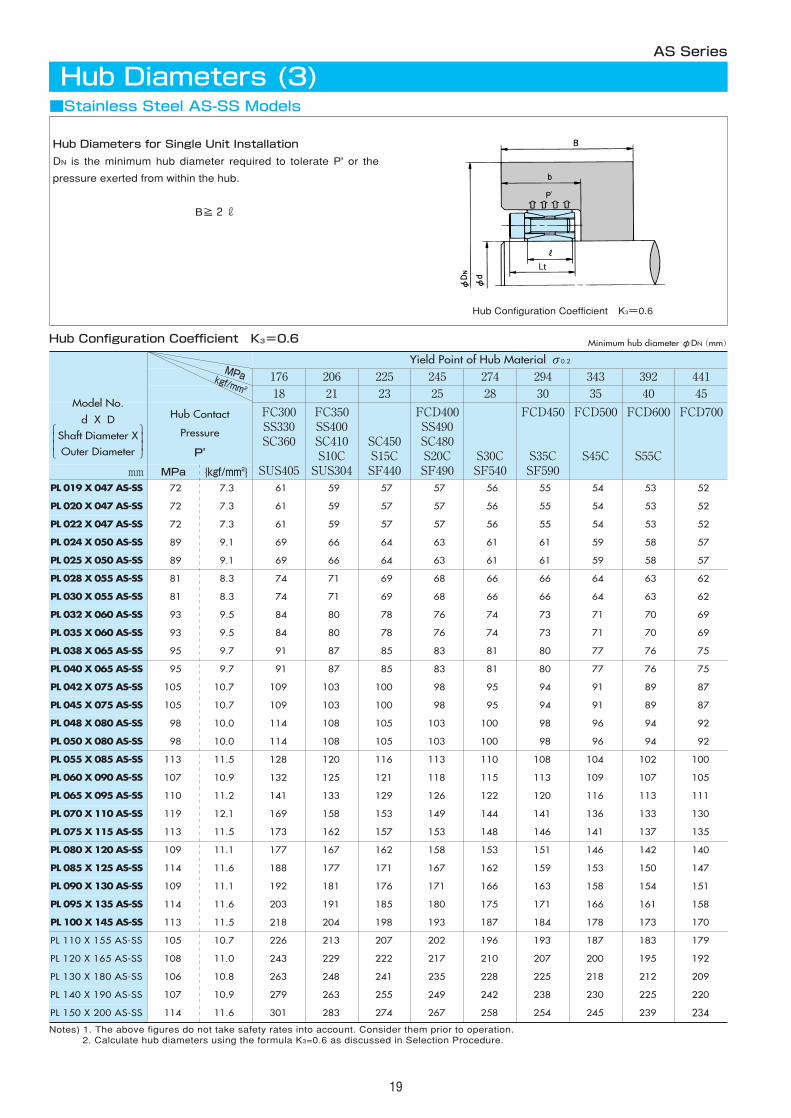
Notes) 1. The above figures do not take safety rates into account. Consider them prior to operation.2. Calculate hub diameters using the formula K3=0.6 as discussed in Selection Procedure.
19
Hub Diameters (3)AS Series
■Stainless Steel AS-SS Models
Lt
Hub Diameters for Single Unit Installation
DN is the minimum hub diameter required to tolerate P' or the
pressure exerted from within the hub.
B≧2r
Hub Configuration Coefficient K3=0.6
Hub Configuration Coefficient K3=0.6
MPakgf/mm 2
Model No.
d X DShaft Diameter XOuter Diameter
Minimum hub diameterφDN(mm)
176 206 225 245 274 294 34318 21 23 25 28 30 35
Hub Contact
Pressure
P'
FC300SS330SC360
SUS405
FC350SS400SC410S10CSUS304
SC450S15CSF440
FCD400SS490SC480S20CSF490
S30CSF540
FCD450
S35CSF590
FCD500
S45Cmm MPa {kgf/mm2}
PL 019 X 047 AS-SS 72 7.3 066 063 061 060 059 058 056
PL 020 X 047 AS-SS 72 7.3 066 063 061 060 059 058 056
PL 022 X 047 AS-SS 72 7.3 066 063 061 060 059 058 056
PL 024 X 050 AS-SS 89 9.1 077 072 070 068 066 065 062
PL 025 X 050 AS-SS 89 9.1 077 072 070 068 066 065 062
PL 028 X 055 AS-SS 81 8.3 082 077 075 073 071 069 067
PL 030 X 055 AS-SS 81 8.3 082 077 075 073 071 069 067
PL 032 X 060 AS-SS 93 9.5 095 088 085 083 080 078 075
PL 035 X 060 AS-SS 93 9.5 095 088 085 083 080 078 075
PL 038 X 065 AS-SS 95 9.7 104 096 093 090 087 085 082
PL 040 X 065 AS-SS 95 9.7 104 096 093 090 087 085 082
PL 042 X 075 AS-SS 105 10.7 126 116 111 108 103 101 097
PL 045 X 075 AS-SS 105 10.7 126 116 111 108 103 101 097
PL 048 X 080 AS-SS 98 10.0 129 120 116 112 108 106 101
PL 050 X 080 AS-SS 98 10.0 129 120 116 112 108 106 101
PL 055 X 085 AS-SS 113 11.5 150 136 130 126 120 117 112
PL 060 X 090 AS-SS 107 10.9 153 141 135 130 125 122 117
PL 065 X 095 AS-SS 110 11.2 165 150 144 139 133 130 124
PL 070 X 110 AS-SS 119 12.1 201 182 173 166 158 154 147
PL 075 X 115 AS-SS 113 11.5 203 184 176 170 162 158 151
PL 080 X 120 AS-SS 109 11.1 207 189 181 174 167 163 156
PL 085 X 125 AS-SS 114 11.6 222 201 192 185 177 173 165
PL 090 X 130 AS-SS 109 11.1 224 205 196 189 181 177 169
PL 095 X 135 AS-SS 114 11.6 239 217 208 200 191 186 178
PL 100 X 145 AS-SS 113 11.5 255 232 222 214 204 200 190
PL 110 X 155 AS-SS 105 10.7 260 239 230 222 213 208 199
PL 120 X 165 AS-SS 108 11.0 282 258 247 239 229 224 214
PL 130 X 180 AS-SS 106 10.8 304 279 268 259 248 243 232
PL 140 X 190 AS-SS 107 10.9 323 296 284 274 263 257 246
PL 150 X 200 AS-SS 114 11.6 354 322 307 296 283 276 263
392 44140 45
FCD600
S55C
FCD700
055 054
055 054
055 054
061 059
061 059
066 064
066 064
073 072
073 072
080 078
080 078
094 091
094 091
098 096
098 096
108 105
113 110
120 117
141 137
146 142
151 147
159 155
163 159
171 167
184 179
193 188
207 202
225 219
238 232
254 247
Yield Point of Hub Material σ0.2
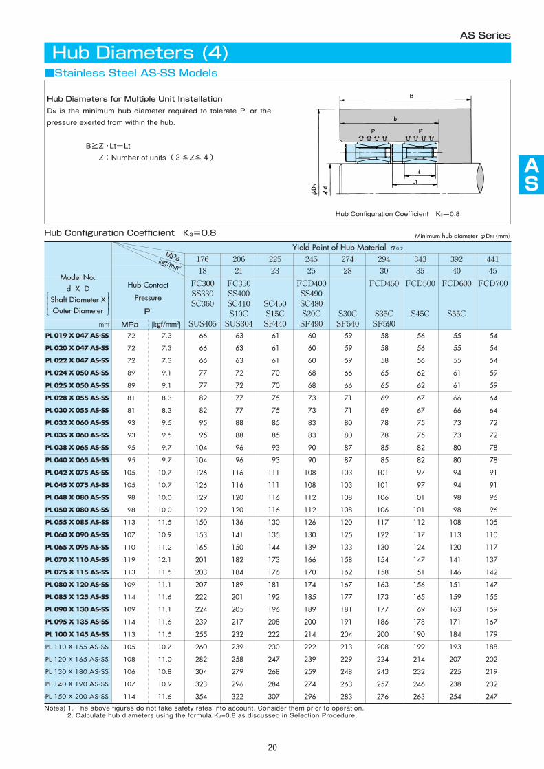
Notes) 1. The above figures do not take safety rates into account. Consider them prior to operation.2. Calculate hub diameters using the formula K3=0.8 as discussed in Selection Procedure.
AS
20
Model No.
d X DShaft Diameter XOuter Diameter
Hub Configuration Coefficient K3=0.8
Hub Diameters (4)AS Series
■Stainless Steel AS-SS Models
Hub Diameters for Multiple Unit Installation
DN is the minimum hub diameter required to tolerate P' or the
pressure exerted from within the hub.
B≧Z・Lt+Lt
Z:Number of units(2≦Z≦4)
Hub Configuration Coefficient K3=0.8
Lt
Minimum hub diameterφDN(mm)
MPakgf/mm 2
21
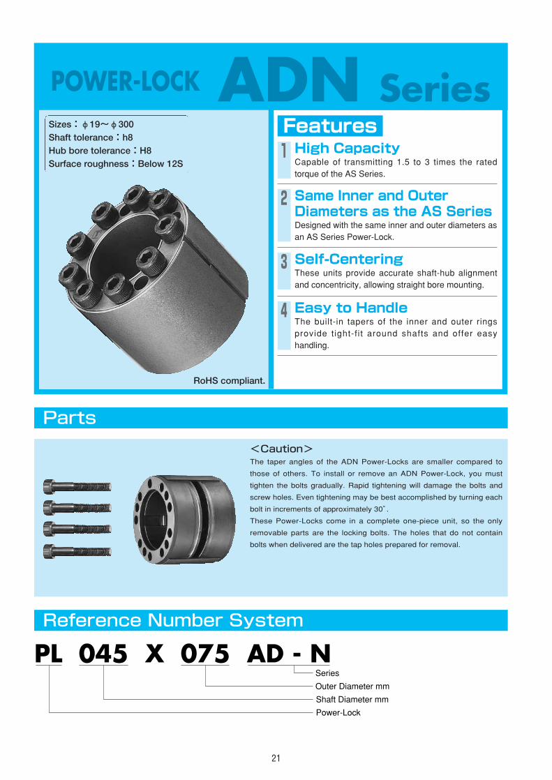
POWER-LOCK ADN SeriesFeaturesSizes:φ19~φ300
Shaft tolerance:h8Hub bore tolerance:H8Surface roughness:Below 12S
1 High CapacityCapable of transmitting 1.5 to 3 times the ratedtorque of the AS Series.
2 Same Inner and OuterDiameters as the AS SeriesDesigned with the same inner and outer diameters asan AS Series Power-Lock.
3 Self-CenteringThese units provide accurate shaft-hub alignmentand concentricity, allowing straight bore mounting.
4 Easy to HandleThe built-in tapers of the inner and outer ringsprovide tight-f i t around shafts and offer easyhandling.
Parts
Reference Number System
<Caution>The taper angles of the ADN Power-Locks are smaller compared to
those of others. To install or remove an ADN Power-Lock, you must
tighten the bolts gradually. Rapid tightening will damage the bolts and
screw holes. Even tightening may be best accomplished by turning each
bolt in increments of approximately 30°.
These Power-Locks come in a complete one-piece unit, so the only
removable parts are the locking bolts. The holes that do not contain
bolts when delivered are the tap holes prepared for removal.
PL 045 X 075 AD - N
Shaft Diameter mm
Power-Lock
Outer Diameter mm
Series
RoHS compliant.
Qty. SizeTightening Torque
MA
Locking Bolts
ASADN
AS
AS
AS
AS
AS
AS
AS
AS
22
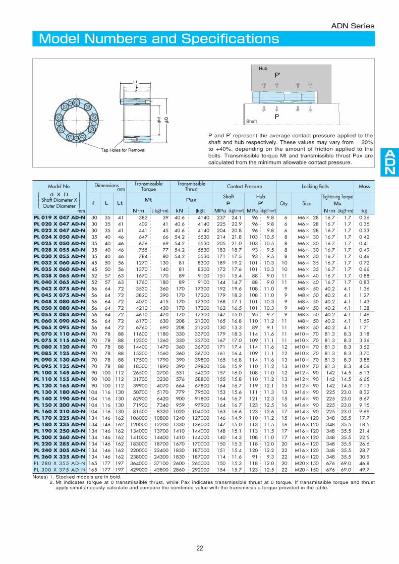
Model No. Dimensionsmm
TransmissibleTorque
TransmissibleThrust Contact Pressure Mass
R L LtMt Pax
ShaftP
HubP'
N・m { kgf・m} kN {kgf} N・m {kgf・m}MPa {kgf/mm2} MPa {kgf/mm2} kg
PL 220 X 285 AD-N 134 146 162 183000 18700 1670 170000 20 M16×120 348 35.5150 15.3 118 12.0 26.6PL 240 X 305 AD-N 134 146 162 220000 22400 1830 187000 22 M16×120 348 35.5151 15.4 120 12.2 28.7PL 260 X 325 AD-N 134 146 162 238000 24300 1830 187000 22 M16×120 348 35.5114 11.6 91 9.3 30.9PL 280 X 355 AD-N 165 177 197 364000 37100 2600 265000 20 M20×150 676 69.0150 15.3 118 12.0 46.8PL 300 X 375 AD-N 165 177 197 429000 43800 2860 292000 22 M20×150 676 69.0154 15.7 123 12.5 49.7
PL 019 X 047 AD-N 30 35 41 382 39 40.6 4140 M6×028 16.7 1.7 237 24.1 96 9.8 0.36PL 020 X 047 AD-N 30 35 41 402 41 40.6 4140 M6×028 16.7 1.7 225 22.9 96 9.8 0.35PL 022 X 047 AD-N 30 35 41 441 45 40.6 4140 M6×028 16.7 1.7 204 20.8 96 9.8 0.33PL 024 X 050 AD-N 35 40 46 647 66 54.2 5530 M6×030 16.7 1.7 214 21.8 103 10.5 0.42PL 025 X 050 AD-N 35 40 46 676 69 54.2 5530 M6×030 16.7 1.7 205 21.0 103 10.5 0.41PL 028 X 055 AD-N 35 40 46 755 77 54.2 5530 8 M6×030 16.7 1.7 183 18.7 93 9.5 0.49PL 030 X 055 AD-N 35 40 46 784 80 54.2 5530 8 M6×030 16.7 1.7 171 17.5 93 9.5 0.46PL 032 X 060 AD-N 45 50 56 1270 130 81 8300 10 M6×035 16.7 1.7 189 19.2 101 10.3 0.72PL 035 X 060 AD-N 45 50 56 1370 140 81 8300 10 M6×035 16.7 1.7 172 17.6 101 10.3 0.66PL 038 X 065 AD-N 52 57 63 1670 170 89 9100 11 M6×040 16.7 1.7 151 15.4 88 9.0 0.88PL 040 X 065 AD-N 52 57 63 1760 180 89 9100 11 M6×040 16.7 1.7 144 14.7 88 9.0 0.83PL 042 X 075 AD-N 56 64 72 3530 360 170 17300 9 M8×050 40.2 4.1 192 19.6 108 11.0 1.36PL 045 X 075 AD-N 56 64 72 3820 390 170 17300 9 M8×050 40.2 4.1 179 18.3 108 11.0 1.27PL 048 X 080 AD-N 56 64 72 4070 415 170 17300 9 M8×050 40.2 4.1 168 17.1 101 10.3 1.43PL 050 X 080 AD-N 56 64 72 4210 430 170 17300 9 M8×050 40.2 4.1 162 16.5 101 10.3 1.38PL 055 X 085 AD-N 56 64 72 4610 470 170 17300 9 M8×050 40.2 4.1 147 15.0 95 9.7 1.49PL 060 X 090 AD-N 56 64 72 6170 630 208 21200 11 M8×050 40.2 4.1 165 16.8 110 11.2 1.59PL 065 X 095 AD-N 56 64 72 6760 690 208 21200 11 M8×050 40.2 4.1 130 13.3 89 9.1 1.71PL 070 X 110 AD-N 70 78 88 11600 1180 330 33700 11 M10×070 81.3 8.3 179 18.3 114 11.6 3.18PL 075 X 115 AD-N 70 78 88 12300 1260 330 33700 11 M10×070 81.3 8.3 167 17.0 109 11.1 3.36PL 080 X 120 AD-N 70 78 88 14400 1470 360 36700 12 M10×070 81.3 8.3 171 17.4 114 11.6 3.52PL 085 X 125 AD-N 70 78 88 15300 1560 360 36700 12 M10×070 81.3 8.3 161 16.4 109 11.1 3.70PL 090 X 130 AD-N 70 78 88 17500 1790 390 39800 13 M10×070 81.3 8.3 165 16.8 114 11.6 3.88PL 095 X 135 AD-N 70 78 88 18500 1890 390 39800 13 M10×070 81.3 8.3 156 15.9 110 11.2 4.06PL 100 X 145 AD-N 90 100 112 26500 2700 531 54200 12 M12×090 142 14.5157 16.0 108 11.0 6.13PL 110 X 155 AD-N 90 100 112 31700 3230 576 58800 13 M12×090 142 14.5155 15.8 110 11.2 6.65PL 120 X 165 AD-N 90 100 112 39900 4070 664 67800 15 M12×090 142 14.5164 16.7 119 12.1 7.13PL 130 X 180 AD-N 104 116 130 50700 5170 779 79500 13 M14×090 225 23.0153 15.6 111 11.3 8.32PL 140 X 190 AD-N 104 116 130 62900 6420 900 91800 15 M14×090 225 23.0164 16.7 121 12.3 8.67PL 150 X 200 AD-N 104 116 130 71900 7340 959 97900 16 M14×090 225 23.0164 16.7 123 12.5 9.15PL 160 X 210 AD-N 104 116 130 81500 8320 1020 104000 17 M14×090 225 23.0163 16.6 123 12.6 9.69PL 170 X 225 AD-N 134 146 162 106000 10800 1240 127000 15 M16×120 348 35.5146 14.9 110 11.2 17.7PL 180 X 235 AD-N 134 146 162 120000 12200 1330 136000 16 M16×120 348 35.5147 15.0 113 11.5 18.5PL 190 X 250 AD-N 134 146 162 134000 13700 1410 144000 17 M16×120 348 35.5148 15.1 113 11.5 21.4PL 200 X 260 AD-N 134 146 162 141000 14400 1410 144000 17 M16×120 348 35.5140 14.3 108 11.0 22.5
Notes) 1. Stocked models are in bold.2. Mt indicates torque at 0 transmissible thrust, while Pax indicates transmissible thrust at 0 torque. If transmissible torque and thrust
apply simultaneously calculate and compare the combined value with the transmissible torque provided in the table.
ADN Series
Model Numbers and Specifications
Lt
Tap Holes for Removal
P and P' represent the average contact pressure applied to theshaft and hub respectively. These values may vary from -20%to +40%, depending on the amount of friction applied to thebolts. Transmissible torque Mt and transmissible thrust Pax arecalculated from the minimum allowable contact pressure.
P'
P
Hub
Shaft
6 6 6 8 8
mm
d X DShaft Diameter XOuter Diameter
206 225 245 274 294 34321 23 25 28 30 35
Hub Contact
Pressure
P'
FC350SS400SC410
FCMB360
SC450S15CSF440
FCD400SS490SC480S20CSF490
S30CSF540
FCD450
S35CSF590
FCD500
S45Cmm MPa {kgf/mm2}
PL 019 X 047 AD-N 96 9.8 63 61 60 59 58 56PL 020 X 047 AD-N 96 9.8 63 61 60 59 58 56PL 022 X 047 AD-N 96 9.8 63 61 60 59 58 56PL 024 X 050 AD-N 103 10.5 69 67 65 63 62 60PL 025 X 050 AD-N 103 10.5 69 67 65 63 62 60PL 028 X 055 AD-N 94 9.5 73 71 70 68 67 65PL 030 X 055 AD-N 94 9.5 73 71 70 68 67 65PL 032 X 060 AD-N 101 10.3 82 79 78 76 74 72PL 035 X 060 AD-N 101 10.3 82 79 78 76 74 72PL 038 X 065 AD-N 89 9.0 85 83 81 80 79 76PL 040 X 065 AD-N 89 9.0 85 83 81 80 79 76PL 042 X 075 AD-N 108 11.0 104 101 99 96 94 91PL 045 X 075 AD-N 108 11.0 104 101 99 96 94 91PL 048 X 080 AD-N 101 10.3 109 106 103 101 99 96PL 050 X 080 AD-N 101 10.3 109 106 103 101 99 96PL 055 X 085 AD-N 95 9.7 113 111 108 105 104 101 PL 060 X 090 AD-N 110 11.2 126 122 119 115 113 110 PL 065 X 095 AD-N 89 9.1 125 122 119 116 115 112 PL 070 X 110 AD-N 114 11.6 156 151 147 142 140 135 PL 075 X 115 AD-N 109 11.1 160 155 152 147 145 140 PL 080 X 120 AD-N 114 11.6 170 165 160 155 153 147 PL 085 X 125 AD-N 109 11.1 174 169 165 160 157 152 PL 090 X 130 AD-N 114 11.6 184 178 174 168 165 160 PL 095 X 135 AD-N 110 11.2 188 183 178 173 170 164 PL 100 X 145 AD-N 108 11.0 201 196 191 185 182 176 PL 110 X 155 AD-N 110 11.2 216 210 205 198 195 189 PL 120 X 165 AD-N 119 12.1 237 229 223 216 212 204 PL 130 X 180 AD-N 111 11.3 252 244 238 231 227 219 PL 140 X 190 AD-N 121 12.3 275 266 258 250 245 236 PL 150 X 200 AD-N 123 12.5 291 281 273 264 259 249
392 44140 45
FCD600
S55C
FCD700
55 5455 5455 5459 5859 5864 6364 6371 6971 6975 7475 7489 8789 8794 9294 9299 97
107 105 110 108 132 129 137 134 144 141 148 146 156 152 160 157 172 169 184 181 199 195 214 210 230 225 242 237
23
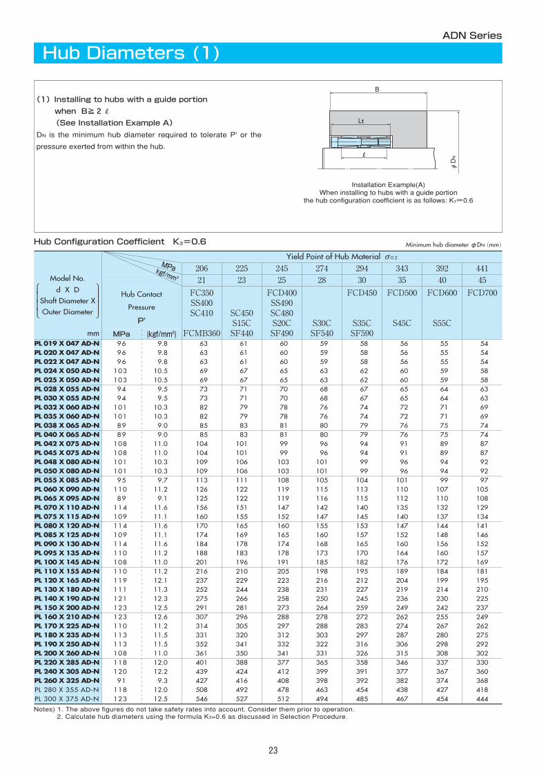
Hub Configuration Coefficient K3=0.6
Notes) 1. The above figures do not take safety rates into account. Consider them prior to operation.2. Calculate hub diameters using the formula K3=0.6 as discussed in Selection Procedure.
MPakgf/mm 2
ADN Series
Hub Diameters (1)
(1)Installing to hubs with a guide portion
when B≧2R
(See Installation Example A)
DN is the minimum hub diameter required to tolerate P' or the
pressure exerted from within the hub.
Installation Example(A)When installing to hubs with a guide portion
the hub configuration coefficient is as follows: K3=0.6
B
Lt
φDN
Minimum hub diameterφDN(mm)
PL 160 X 210 AD-N 123 12.6 307 296 288 278 272 262 255 249 PL 170 X 225 AD-N 110 11.2 314 305 297 288 283 274 267 262 PL 180 X 235 AD-N 113 11.5 331 320 312 303 297 287 280 275 PL 190 X 250 AD-N 113 11.5 352 341 332 322 316 306 298 292 PL 200 X 260 AD-N 108 11.0 361 350 341 331 326 315 308 302 PL 220 X 285 AD-N 118 12.0 401 388 377 365 358 346 337 330 PL 240 X 305 AD-N 120 12.2 439 424 412 399 391 377 367 360 PL 260 X 325 AD-N 91 9.3 427 416 408 398 392 382 374 368 PL 280 X 355 AD-N 118 12.0 508 492 478 463 454 438 427 418 PL 300 X 375 AD-N 123 12.5 546 527 512 494 485 467 454 444
Yield Point of Hub Material σ0.2
Model No.
d X DShaft Diameter XOuter Diameter
206 225 245 274 294 34321 23 25 28 30 35
Hub Contact
Pressure
P'
FC350SS400SC410
FCMB360
SC450S15CSF440
FCD400SS490SC480S20CSF490
S30CSF540
FCD450
S35CSF590
FCD500
S45Cmm MPa {kgf/mm2}
PL 019 X 047 AD-N 96 9.8 78 74 71 68 66 63PL 020 X 047 AD-N 96 9.8 78 74 71 68 66 63PL 022 X 047 AD-N 96 9.8 78 74 71 68 66 63PL 024 X 050 AD-N 103 10.5 87 82 79 75 73 69PL 025 X 050 AD-N 103 10.5 87 82 79 75 73 69PL 028 X 055 AD-N 94 9.5 90 86 83 79 77 73PL 030 X 055 AD-N 94 9.5 90 86 83 79 77 73PL 032 X 060 AD-N 101 10.3 103 97 93 89 86 82PL 035 X 060 AD-N 101 10.3 103 97 93 89 86 82PL 038 X 065 AD-N 89 9.0 103 99 95 91 86 85PL 040 X 065 AD-N 89 9.0 103 99 95 91 89 85PL 042 X 075 AD-N 108 11.0 134 127 121 114 111 104PL 045 X 075 AD-N 108 11.0 134 127 121 114 111 104PL 048 X 080 AD-N 101 10.3 137 130 124 118 115 109PL 050 X 080 AD-N 101 10.3 137 130 124 118 115 109PL 055 X 085 AD-N 95 9.7 140 134 128 122 119 113PL 060 X 090 AD-N 110 11.2 163 154 146 138 134 126PL 065 X 095 AD-N 89 9.1 152 145 140 134 131 125PL 070 X 110 AD-N 114 11.6 206 192 182 172 166 156PL 075 X 115 AD-N 109 11.1 208 195 186 175 170 160PL 080 X 120 AD-N 114 11.6 224 210 199 187 181 170PL 085 X 125 AD-N 109 11.1 226 213 202 191 185 174PL 090 X 130 AD-N 114 11.6 243 227 216 203 196 184PL 095 X 135 AD-N 110 11.2 245 230 219 207 200 188PL 100 X 145 AD-N 108 11.0 261 245 233 220 214 201PL 110 X 155 AD-N 110 11.2 281 264 251 237 230 216PL 120 X 165 AD-N 119 12.1 319 297 281 263 254 237PL 130 X 180 AD-N 111 11.3 328 308 293 276 268 252PL 140 X 190 AD-N 121 12.3 373 346 327 305 295 275PL 150 X 200 AD-N 123 12.5 397 368 347 324 312 291
392 44140 45
FCD600
S55C
FCD700
61 5961 5961 5966 6466 6471 6971 6979 7679 7682 8082 80
100 97100 97105 101105 101109 106120 116120 117149 144153 148162 157167 161176 170180 175193 187207 200226 218241 233262 252277 266
PL 160 X 210 AD-N 123 12.6 422 390 367 342 330 307 292 281PL 170 X 225 AD-N 110 11.2 409 384 365 345 334 314 301 291PL 180 X 235 AD-N 113 11.5 434 407 386 364 352 331 316 305PL 190 X 250 AD-N 113 11.5 461 432 411 387 374 352 336 325PL 200 X 260 AD-N 108 11.0 465 438 418 395 383 361 345 334PL 220 X 285 AD-N 118 12.0 538 501 474 444 429 401 382 369PL 240 X 305 AD-N 120 12.2 591 549 519 486 469 439 418 403PL 260 X 325 AD-N 91 9.3 522 499 480 459 448 427 412 401PL 280 X 355 AD-N 118 12.0 682 635 600 563 543 508 485 467PL 300 X 375 AD-N 123 12.5 747 691 651 607 586 546 519 500
Yield Point of Hub Material σ0.2
ASADN
AS
AS
AS
AS
AS
AS
AS
AS
24
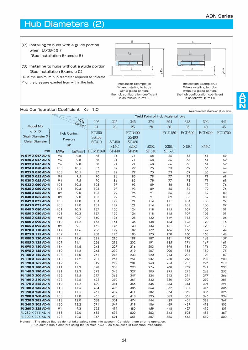
Notes) 1. The above figures do not take safety rates into account. Consider them prior to operation.2. Calculate hub diameters using the formula K3=1.0 as discussed in Selection Procedure.
Hub Configuration Coefficient K3=1.0
ADN Series
Hub Diameters (2)
(2)Installing to hubs with a guide portion
when Lt<B<2R
(See Installation Example B)
(3)Installing to hubs without a guide portion
(See Installation Example C)
DN is the minimum hub diameter required to tolerate
P' or the pressure exerted from within the hub. Installation Example(B)When installing to hubswith a guide portion,
the hub configuration coefficientis as follows: K3=1.0
Installation Example(C)When installing to hubswithout a guide portion,
the hub configuration coefficientis as follows: K3=1.0
B
Lt
φDN
B
Lt
φDN
MPakgf/mm 2
Minimum hub diameterφDN(mm)
Model No.
d X DShaft Diameter XOuter Diameter
25
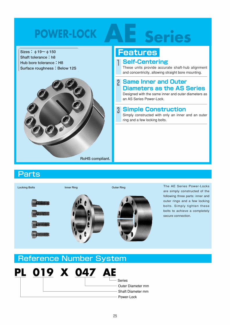
POWER-LOCK AE SeriesFeaturesSizes:φ19~φ150
Shaft tolerance:h8Hub bore tolerance:H8Surface roughness:Below 12S
1 Self-CenteringThese units provide accurate shaft-hub alignmentand concentricity, allowing straight bore mounting.
3 Simple ConstructionSimply constructed with only an inner and an outerring and a few locking bolts.
Parts
Reference Number System
The AE Series Power-Locks
are simply constructed of the
following three parts: inner and
outer rings and a few locking
bolts. Simply t ighten these
bolts to achieve a completely
secure connection.
PL 019 X 047 AE
Shaft Diameter mm
Power-Lock
Outer Diameter mm
Series
Locking Bolts Inner Ring Outer Ring
2 Same Inner and OuterDiameters as the AS SeriesDesigned with the same inner and outer diameters asan AS Series Power-Lock.
RoHS compliant.
AS
AS
AE
AS
AS
AS
AS
AS
AS
AS
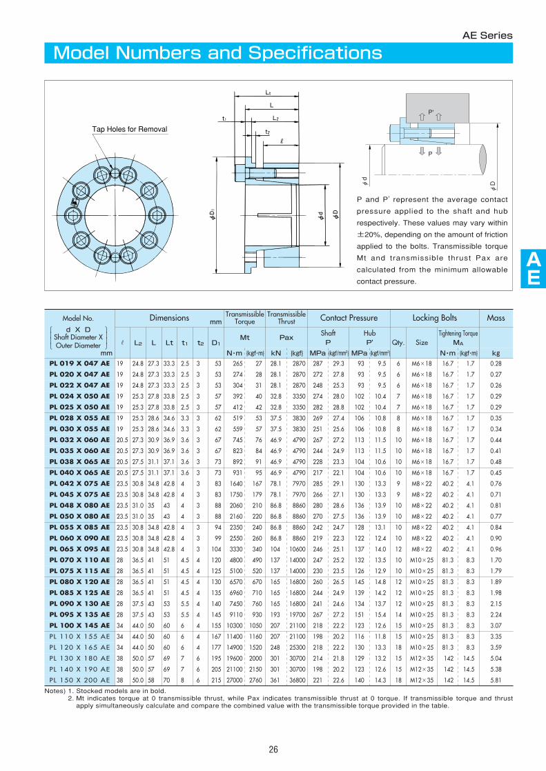
26
Notes) 1. Stocked models are in bold.2. Mt indicates torque at 0 transmissible thrust, while Pax indicates transmissible thrust at 0 torque. If transmissible torque and thrust
apply simultaneously calculate and compare the combined value with the transmissible torque provided in the table.
Dimensions mmTransmissible
TorqueTransmissible
Thrust Contact Pressure Locking Bolts Mass
r L2 L Lt t1 t2 D1Mt Pax
ShaftP
HubP' Qty. Size
Tightening TorqueMA
N・m {kgf・m} kN {kgf} MPa {kgf/mm2} MPa {kgf/mm2} N・m {kgf・m} kgPL 019 X 047 AE 19 24.8 27.3 33.3 2.5 3 53 265 27 28.1 2870 287 29.3 93 9.5 6 M6×18 16.7 1.7 0.28
PL 020 X 047 AE 19 24.8 27.3 33.3 2.5 3 53 274 28 28.1 2870 272 27.8 93 9.5 6 M6×18 16.7 1.7 0.27
PL 022 X 047 AE 19 24.8 27.3 33.3 2.5 3 53 304 31 28.1 2870 248 25.3 93 9.5 6 M6×18 16.7 1.7 0.26
PL 024 X 050 AE 19 25.3 27.8 33.8 2.5 3 57 392 40 32.8 3350 274 28.0 102 10.4 7 M6×18 16.7 1.7 0.29
PL 025 X 050 AE 19 25.3 27.8 33.8 2.5 3 57 412 42 32.8 3350 282 28.8 102 10.4 7 M6×18 16.7 1.7 0.29
PL 028 X 055 AE 19 25.3 28.6 34.6 3.3 3 62 519 53 37.5 3830 269 27.4 106 10.8 8 M6×18 16.7 1.7 0.35
PL 030 X 055 AE 19 25.3 28.6 34.6 3.3 3 62 559 57 37.5 3830 251 25.6 106 10.8 8 M6×18 16.7 1.7 0.34
PL 032 X 060 AE 20.5 27.3 30.9 36.9 3.6 3 67 745 76 46.9 4790 267 27.2 113 11.5 10 M6×18 16.7 1.7 0.44
PL 035 X 060 AE 20.5 27.3 30.9 36.9 3.6 3 67 823 84 46.9 4790 244 24.9 113 11.5 10 M6×18 16.7 1.7 0.41
PL 038 X 065 AE 20.5 27.5 31.1 37.1 3.6 3 73 892 91 46.9 4790 228 23.3 104 10.6 10 M6×18 16.7 1.7 0.48
PL 040 X 065 AE 20.5 27.5 31.1 37.1 3.6 3 73 931 95 46.9 4790 217 22.1 104 10.6 10 M6×18 16.7 1.7 0.45
PL 042 X 075 AE 23.5 30.8 34.8 42.8 4 3 83 1640 167 78.1 7970 285 29.1 130 13.3 9 M8×22 40.2 4.1 0.76
PL 045 X 075 AE 23.5 30.8 34.8 42.8 4 3 83 1750 179 78.1 7970 266 27.1 130 13.3 9 M8×22 40.2 4.1 0.71
PL 048 X 080 AE 23.5 31.0 35 43 4 3 88 2060 210 86.8 8860 280 28.6 136 13.9 10 M8×22 40.2 4.1 0.81
PL 050 X 080 AE 23.5 31.0 35 43 4 3 88 2160 220 86.8 8860 270 27.5 136 13.9 10 M8×22 40.2 4.1 0.77
PL 055 X 085 AE 23.5 30.8 34.8 42.8 4 3 94 2350 240 86.8 8860 242 24.7 128 13.1 10 M8×22 40.2 4.1 0.84
PL 060 X 090 AE 23.5 30.8 34.8 42.8 4 3 99 2550 260 86.8 8860 219 22.3 122 12.4 10 M8×22 40.2 4.1 0.90
PL 065 X 095 AE 23.5 30.8 34.8 42.8 4 3 104 3330 340 104 10600 246 25.1 137 14.0 12 M8×22 40.2 4.1 0.96
PL 070 X 110 AE 28 36.5 41 51 4.5 4 120 4800 490 137 14000 247 25.2 132 13.5 10 M10×25 81.3 8.3 1.70
PL 075 X 115 AE 28 36.5 41 51 4.5 4 125 5100 520 137 14000 230 23.5 126 12.9 10 M10×25 81.3 8.3 1.79
PL 080 X 120 AE 28 36.5 41 51 4.5 4 130 6570 670 165 16800 260 26.5 145 14.8 12 M10×25 81.3 8.3 1.89
PL 085 X 125 AE 28 36.5 41 51 4.5 4 135 6960 710 165 16800 244 24.9 139 14.2 12 M10×25 81.3 8.3 1.98
PL 090 X 130 AE 28 37.5 43 53 5.5 4 140 7450 760 165 16800 241 24.6 134 13.7 12 M10×25 81.3 8.3 2.15
PL 095 X 135 AE 28 37.5 43 53 5.5 4 145 9110 930 193 19700 267 27.2 151 15.4 14 M10×25 81.3 8.3 2.24
PL 100 X 145 AE 34 44.0 50 60 6 4 155 10300 1050 207 21100 218 22.2 123 12.6 15 M10×25 81.3 8.3 3.07
PL 110 X 155 AE 34 44.0 50 60 6 4 167 11400 1160 207 21100 198 20.2 116 11.8 15 M10×25 81.3 8.3 3.35
PL 120 X 165 AE 34 44.0 50 60 6 4 177 14900 1520 248 25300 218 22.2 130 13.3 18 M10×25 81.3 8.3 3.59
PL 130 X 180 AE 38 50.0 57 69 7 6 195 19600 2000 301 30700 214 21.8 129 13.2 15 M12×35 142 14.5 5.04
PL 140 X 190 AE 38 50.0 57 69 7 6 205 21100 2150 301 30700 198 20.2 123 12.6 15 M12×35 142 14.5 5.38
PL 150 X 200 AE 38 50.0 58 70 8 6 215 27000 2760 361 36800 221 22.6 140 14.3 18 M12×35 142 14.5 5.81
AE Series
Model Numbers and Specifications
Tap Holes for Removal
P and P' represent the average contact
pressure applied to the shaft and hub
respectively. These values may vary within
±20%, depending on the amount of friction
applied to the bolts. Transmissible torque
Mt and transmissible thrust Pax are
calculated from the minimum allowable
contact pressure.
P
P'
φd
φD
mm
Model No.
d X DShaft Diameter XOuter Diameter
206 225 245 274 294 34521 23 25 28 30 35
Hub Contact
Pressure
P'
FC350SS400SC410 S10CFCMB360
SC450S15CSF440
FCD400SS490SC480S20CSF490
S30CSF540
FCD450
S35CSF590
FCD500
S45Cmm MPa {kgf/mm2}
PL 019 X 047 AE 93 9.5 69 67 65 63 61 59
PL 020 X 047 AE 93 9.5 69 67 65 63 61 59
PL 022 X 047 AE 93 9.5 69 67 65 63 61 59
PL 024 X 050 AE 102 10.4 77 74 71 68 67 64
PL 025 X 050 AE 102 10.4 77 74 71 68 67 64
PL 028 X 055 AE 106 10.8 86 82 79 76 74 71
PL 030 X 055 AE 106 10.8 86 82 79 76 74 71
PL 032 X 060 AE 113 11.5 96 92 89 85 83 79
PL 035 X 060 AE 113 11.5 96 92 89 85 83 79
PL 038 X 065 AE 104 10.6 100 96 93 89 87 84
PL 040 X 065 AE 104 10.6 100 96 93 89 87 84
PL 042 X 075 AE 130 13.3 132 124 119 112 109 103
PL 045 X 075 AE 130 13.3 132 124 119 112 109 103
PL 048 X 080 AE 136 13.9 145 136 130 122 119 112
PL 050 X 080 AE 136 13.9 145 136 130 122 119 112
PL 055 X 085 AE 128 13.1 148 139 133 126 123 116
PL 060 X 090 AE 122 12.4 151 143 137 131 127 121
PL 065 X 095 AE 137 14.0 173 162 154 146 141 133
PL 070 X 110 AE 132 13.5 195 184 175 166 161 152
PL 075 X 115 AE 126 12.9 197 187 179 170 165 156
PL 080 X 120 AE 145 14.8 228 213 201 189 183 171
PL 085 X 125 AE 139 14.2 230 215 205 193 187 176
PL 090 X 130 AE 134 13.7 232 219 209 197 191 180
PL 095 X 135 AE 151 15.4 265 246 232 217 209 195
PL 100 X 145 AE 123 12.6 245 233 223 212 206 196
PL 110 X 155 AE 116 11.8 252 240 231 221 215 205
PL 120 X 165 AE 130 13.3 289 273 260 247 240 226
PL 130 X 180 AE 129 13.2 313 296 283 268 260 246
PL 140 X 190 AE 123 12.6 321 305 292 277 270 256
PL 150 X 200 AE 140 14.3 369 346 328 309 299 281
392 44140 45
FCD600
S55C
FCD700
57 56
57 56
57 56
62 61
62 61
69 67
69 67
76 74
76 74
81 79
81 79
99 96
99 96
107 103
107 103
112 108
116 113
127 123
146 141
150 146
163 158
168 162
173 167
186 179
188 183
198 192
217 210
236 229
246 239
269 260
Yield Point of Hub Material σ0.2
27
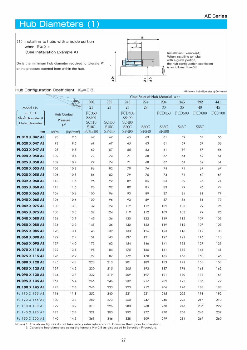
Notes) 1. The above figures do not take safety rates into account. Consider them prior to operation.2. Calculate hub diameters using the formula K3=0.8 as discussed in Selection Procedure.
AE Series
Hub Diameters (1)
(1)Installing to hubs with a guide portion
when B≧2R
(See Installation Example A)
DN is the minimum hub diameter required to tolerate P'
or the pressure exerted from within the hub.
Installation Example(A)When installing to hubswith a guide portion,the hub configuration coefficientis as follows: K3=0.8
Hub Configuration Coefficient K3=0.8 Minimum hub diameterφDN(mm)
MPakgf/mm 2
Model No.
d X DShaft Diameter XOuter Diameter
206 225 245 274 294 34521 23 25 28 30 35
Hub Contact
Pressure
P'
FC350SS400SC410 S10CFCMB360
SC450S15CSF440
FCD400SS490SC480S20CSF490
S30CSF540
FCD450
S35CSF590
FCD500
S45Cmm MPa {kgf/mm2}
PL 019 X 047 AE 93 9.5 77 73 71 67 66 63
PL 020 X 047 AE 93 9.5 77 73 71 67 66 63
PL 022 X 047 AE 93 9.5 77 73 71 67 66 63
PL 024 X 050 AE 102 10.4 87 82 78 74 72 68
PL 025 X 050 AE 102 10.4 87 82 78 74 72 68
PL 028 X 055 AE 106 10.8 98 92 88 83 81 76
PL 030 X 055 AE 106 10.8 98 92 88 83 81 76
PL 032 X 060 AE 113 11.5 111 104 99 93 90 85
PL 035 X 060 AE 113 11.5 111 104 99 93 90 85
PL 038 X 065 AE 104 10.6 114 107 103 97 95 89
PL 040 X 065 AE 104 10.6 114 107 103 97 95 89
PL 042 X 075 AE 130 13.3 159 146 136 126 121 112
PL 045 X 075 AE 130 13.3 159 146 136 126 121 112
PL 048 X 080 AE 136 13.9 178 162 150 138 133 122
PL 050 X 080 AE 136 13.9 178 162 150 138 133 122
PL 055 X 085 AE 128 13.1 177 163 153 142 136 126
PL 060 X 090 AE 122 12.4 178 165 156 145 140 131
PL 065 X 095 AE 137 14.0 213 193 179 165 158 146
PL 070 X 110 AE 132 13.5 236 216 202 187 179 166
PL 075 X 115 AE 126 12.9 236 217 204 190 183 170
PL 080 X 120 AE 145 14.8 289 258 238 217 207 189
PL 085 X 125 AE 139 14.2 285 258 239 219 210 193
PL 090 X 130 AE 134 13.7 284 259 241 222 213 197
PL 095 X 135 AE 151 15.4 345 304 277 251 239 217
PL 100 X 145 AE 123 12.6 290 269 253 236 227 212
PL 110 X 155 AE 116 11.8 293 274 259 243 235 221
PL 120 X 165 AE 130 13.3 349 320 299 277 266 247
PL 130 X 180 AE 129 13.2 377 346 324 301 289 268
PL 140 X 190 AE 123 12.6 380 352 331 309 298 277
PL 150 X 200 AE 140 14.3 460 415 384 352 336 309
392 44140 45
FCD600
S55C
FCD700
60 59
60 59
60 59
66 64
66 64
73 71
73 71
81 78
81 78
86 83
86 83
106 102
106 102
115 111
115 111
120 115
125 120
137 132
157 150
161 155
177 169
182 174
186 179
203 193
201 194
211 203
234 224
254 244
264 254
291 278
Yield Point of Hub Material σ0.2
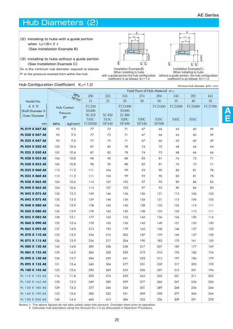
Notes) 1. The above figures do not take safety rates into account. Consider them prior to operation.2. Calculate hub diameters using the formula K3=1.0 as discussed in Selection Procedure.
AS
AS
AE
AS
AS
AS
AS
AS
AS
AS
28
AE Series
Hub Diameters (2)
(2)Installing to hubs with a guide portion
when L2<B<2R
(See Installation Example B)
(3)Installing to hubs without a guide portion
(See Installation Example C)
DN is the minimum hub diameter required to tolerate
P' or the pressure exerted from within the hub.
Hub Configuration Coefficient K3=1.0 Minimum hub diameterφDN(mm)
MPakgf/mm 2
Model No.
d X DShaft Diameter XOuter Diameter
Installation Example(B)When installing to hubs
with a guide portion,the hub configurationcoefficient is as follows: K3=1.0
Installation Example(C)When installing to hubs
without a guide portion, the hub configurationcoefficient is as follows: K3=1.0
29
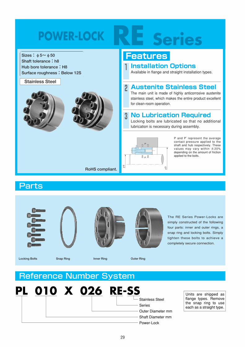
POWER-LOCK RE SeriesFeaturesSizes:φ5~φ50
Shaft tolerance:h8Hub bore tolerance:H8Surface roughness:Below 12S
1 Installation OptionsAvailable in flange and straight installation types.
2 Austenite Stainless SteelThe main unit is made of highly anticorrosive austenitestainless steel, which makes the entire product excellentfor clean-room operation.
P and P ' represent the averagecontact pressure applied to theshaft and hub respectively. Thesevalues may vary within ±20%depending on the amount of frictionapplied to the bolts.
3 No Lubrication RequiredLocking bolts are lubricated so that no additionallubrication is necessary during assembly.
Parts
Reference Number System
The RE Series Power-Locks are
simply constructed of the following
four parts: inner and outer rings, a
snap ring and locking bolts. Simply
tighten these bolts to achieve a
completely secure connection.
PL 010 X 026 RE-SS
Shaft Diameter mm
Power-Lock
Outer Diameter mm
Series
Stainless SteelUnits are shipped as flange types. Remove the snap ring to use each as a straight type.
Locking Bolts Snap Ring Inner Ring Outer Ring
Stainless Steel
P
P'
φd
φD
RoHS compliant.
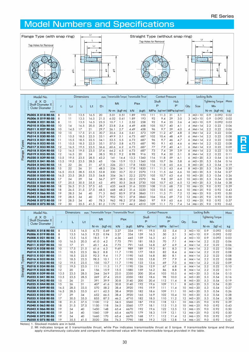
Dimensions Transmissible Torque Transmissible Thrust Contact Pressure Locking Bolts Mass
r L LtMt Pax
ShaftP
HubP′ Qty. Size
Tightening Torque
MA
N・m {kgf・m} kN {kgf} MPa MPa N・m kgPL005 X 018 RE-SS 8 13.5 16.5 6.73 0.69 3.27 334 191 19.5 53 5.4 3 M3×10 0.9 0.092 0.02PL006 X 019 RE-SS 8 13.5 16.5 9.23 0.94 3.27 334 159 16.3 50 5.1 3 M3×10 0.9 0.092 0.02PL008 X 021 RE-SS 8 13.5 16.5 18.5 1.9 4.36 445 159 16.3 61 6.2 4 M3×10 0.9 0.092 0.03PL010 X 026 RE-SS 10 16.5 20.5 41.0 4.2 7.75 791 181 18.5 70 7.1 4 M4×14 2.2 0.22 0.06PL011 X 027 RE-SS 10 17 21 45.1 4.6 7.75 791 165 16.8 67 6.9 4 M4×14 2.2 0.22 0.06PL012 X 028 RE-SS 10 17.5 21.5 61.6 6.3 9.69 989 189 19.3 81 8.3 5 M4×14 2.2 0.22 0.06PL014 X 030 RE-SS 11 18.5 22.5 86.2 8.8 11.7 1190 177 18.0 82 8.4 6 M4×14 2.2 0.22 0.08PL015 X 031 RE-SS 11 18.5 22.5 92.3 9.4 11.7 1190 165 16.8 80 8.1 6 M4×14 2.2 0.22 0.08PL016 X 032 RE-SS 11 18.5 22.5 98.5 10.1 11.7 1190 155 15.8 77 7.9 6 M4×14 2.2 0.22 0.08PL017 X 033 RE-SS 12 19.5 23.5 105 10.7 11.7 1190 133 13.6 69 7.0 6 M4×14 2.2 0.22 0.09PL018 X 034 RE-SS 12 19.5 23.5 111 11.3 11.7 1190 126 12.9 67 6.8 6 M4×14 2.2 0.22 0.10PL019 X 035 RE-SS 12 20 24 156 15.9 15.5 1580 159 16.2 86 8.8 8 M4×14 2.2 0.22 0.11PL020 X 039 RE-SS 13.5 23.5 28.5 244 24.9 23.0 2350 200 20.4 103 10.5 6 M5×20 5.3 0.54 0.15PL022 X 041 RE-SS 13.5 23.5 28.5 269 27.4 23.0 2350 182 18.6 98 10.0 6 M5×20 5.3 0.54 0.16PL024 X 043 RE-SS 15 26 31 391 39.9 30.8 3140 200 20.4 112 11.4 8 M5×20 5.3 0.54 0.19PL025 X 044 RE-SS 15 26 31 407 41.6 30.8 3140 192 19.6 109 11.1 8 M5×20 5.3 0.54 0.20PL028 X 049 RE-SS 16.5 28.5 33.5 570 58.2 38.4 3920 195 19.9 111 11.4 10 M5×20 5.3 0.54 0.27PL030 X 050 RE-SS 16.5 28.5 33.5 611 62.3 38.4 3920 182 18.6 109 11.1 10 M5×20 5.3 0.54 0.26PL032 X 052 RE-SS 17 29 34 652 66.5 38.4 3920 165 16.9 102 10.4 10 M5×20 5.3 0.54 0.28PL035 X 058 RE-SS 17 30.5 35.5 855 87.3 46.2 4710 182 18.5 110 11.2 12 M5×20 5.3 0.54 0.38PL038 X 060 RE-SS 18 31.5 37.5 1100 112 54.5 5560 187 19.0 118 12.1 10 M6×25 9.0 0.92 0.39PL040 X 063 RE-SS 18 31.5 37.5 1150 118 54.5 5560 177 18.1 113 11.5 10 M6×25 9.0 0.92 0.43PL042 X 066 RE-SS 19 34 40 1450 148 65.4 6670 192 19.6 122 12.5 12 M6×25 9.0 0.92 0.50PL045 X 068 RE-SS 19 34 40 1560 159 65.4 6670 179 18.3 119 12.1 12 M6×25 9.0 0.92 0.50PL048 X 072 RE-SS 19 34 40 1660 170 65.4 6670 168 17.1 112 11.4 12 M6×25 9.0 0.92 0.57PL050 X 075 RE-SS 19 35.5 41.5 2020 206 76.3 7790 188 19.2 125 12.8 14 M6×25 9.0 0.92 0.62
{kg f/mm2} {kg f/mm2} {kg f・m}
AS
AS
AS
RE
AS
AS
AS
AS
AS
AS
30
Notes) 1. Stocked models are in bold.2. Mt indicates torque at 0 transmissible thrust, while Pax indicates transmissible thrust at 0 torque. If transmissible torque and thrust
apply simultaneously calculate and compare the combined value with the transmissible torque provided in the table.
RE Series
Model Numbers and SpecificationsFlange Type (with snap ring) Straight Type (without snap ring)
Tap Holes for Removal
Tap Holes for Removal
Dimensions mm
mm
Locking Bolts
r L2 L Lt D1
Tightening Torque
MA
N・m kg
PL038 X 060 RE-SS 18 26.5 31.5 37.5 65 9.0 0.39
Transmissible Torque Transmissible Thrust
Mt Pax Qty.
N・m {kgf・m} kN {kgf}
Size
635 64.8 31.6 3220 10 M6×25
Contact PressureMassShaft
P
HubP′
MPa {kgf/mm2} MPa {kgf/mm2} {kgf・m}PL005 X 018 RE-SS 8 11 13.5 16.5 20 5.01 0.51 1.89 193 111 11.3 31 3.1 3 M3×10 0.9 0.092 0.02PL006 X 019 RE-SS 8 11 13.5 16.5 21.5 6.02 0.61 1.89 193 92 9.4 29 3.0 3 M3×10 0.9 0.092 0.02PL008 X 021 RE-SS 8 11 13.5 16.5 23.5 10.7 1.1 2.52 258 92 9.4 35 3.6 4 M3×10 0.9 0.092 0.03PL010 X 026 RE-SS 10 14 16.5 20.5 28.7 23.8 2.4 4.49 458 105 10.7 40 4.1 4 M4×14 2.2 0.22 0.06PL011 X 027 RE-SS 10 14.5 17 21 29.7 26.1 2.7 4.49 458 96 9.7 39 4.0 4 M4×14 2.2 0.22 0.06PL012 X 028 RE-SS 10 15 17.5 21.5 30.7 35.6 3.6 5.61 573 109 11.2 47 4.8 5 M4×14 2.2 0.22 0.06PL014 X 030 RE-SS 11 15.5 18.5 22.5 33.1 49.9 5.1 6.73 687 102 10.4 48 4.9 6 M4×14 2.2 0.22 0.08PL015 X 031 RE-SS 11 15.5 18.5 22.5 34.1 53.5 5.5 6.73 687 96 9.7 46 4.7 6 M4×14 2.2 0.22 0.08PL016 X 032 RE-SS 11 15.5 18.5 22.5 35.1 57.0 5.8 6.73 687 90 9.1 45 4.6 6 M4×14 2.2 0.22 0.08PL017 X 033 RE-SS 12 16.5 19.5 23.5 36.6 60.6 6.2 6.73 687 77 7.9 40 4.1 6 M4×14 2.2 0.22 0.09PL018 X 034 RE-SS 12 16.5 19.5 23.5 37.6 64.2 6.5 6.73 687 73 7.4 39 3.9 6 M4×14 2.2 0.22 0.10PL019 X 035 RE-SS 12 16.5 20 24 38.5 90.3 9.2 8.98 916 92 9.4 50 5.1 8 M4×14 2.2 0.22 0.11PL020 X 039 RE-SS 13.5 19.5 23.5 28.5 43.2 141 14.4 13.3 1360 116 11.8 59 6.1 6 M5×20 5.3 0.54 0.15PL022 X 041 RE-SS 13.5 19.5 23.5 28.5 45 156 15.9 13.3 1360 105 10.7 56 5.8 6 M5×20 5.3 0.54 0.16PL024 X 043 RE-SS 15 22 26 31 47.5 226 23.1 17.8 1820 116 11.8 65 6.6 8 M5×20 5.3 0.54 0.19PL025 X 044 RE-SS 15 22 26 31 48.5 236 24.1 17.8 1820 111 11.3 63 6.4 8 M5×20 5.3 0.54 0.20PL028 X 049 RE-SS 16.5 23.5 28.5 33.5 53.8 330 33.7 22.2 2270 113 11.5 64 6.6 10 M5×20 5.3 0.54 0.27PL030 X 050 RE-SS 16.5 23.5 28.5 33.5 54.8 354 36.1 22.2 2270 105 10.7 63 6.4 10 M5×20 5.3 0.54 0.26PL032 X 052 RE-SS 17 24 29 34 56.7 377 38.5 22.2 2270 96 9.8 59 6.0 10 M5×20 5.3 0.54 0.28PL035 X 058 RE-SS 17 25.5 30.5 35.5 63 495 50.5 26.8 2730 105 10.7 63 6.5 12 M5×20 5.3 0.54 0.38
108 11.0 68 7.0 0.92
PL042 X 066 RE-SS 19 28.5 34 40 71.3 842 85.9 37.8 3860 111 11.3 71 7.2 12 M6×25 9.0 0.92 0.50PL045 X 068 RE-SS 19 28.5 34 40 73.7 902 92.1 37.8 3860 104 10.6 69 7.0 12 M6×25 9.0 0.92 0.50PL048 X 072 RE-SS 19 28.5 34 40 78.3 962 98.2 37.8 3860 97 9.9 65 6.6 12 M6×25 9.0 0.92 0.57PL050 X 075 RE-SS 19 30 35.5 41.5 81.2 1170 119 44.2 4510 109 11.1 73 7.4 14 M6×25 9.0 0.92 0.62
PL040 X 063 RE-SS 18 26.5 31.5 37.5 68.5 668 68.2 31.6 3220 103 10.5 65 6.6 10 M6×25 9.0 0.92 0.43
FlangeTypes
StraightTypes
Model No.d X D
Shaft Diameter XOuter Diameter
Model No.d X D
Shaft Diameter XOuter Diameter
mm
mm
31
Notes) 1. The above figures do not take safety rates into account. Consider them prior to operation.2. Calculate hub diameters using the formula, K3=0.8 or 1.0 as discussed in Selection Procedure.
Model No. MPa 147 176 206 225 245 274 294 343 392 441
{kgf/mm2} 15 18 21 23 25 28 30 35 40 45
Hub ContactPressureP'
FC250 FC300SS330SC360
SUS405
FC350SS400SC410S10CSUS304
SC450S15CSF440
FCD400SS490SC480S20CSF490
S30CSF540
FCD450
S35CSF590
FCD500
S45C
FCD600
S55C
FCD700
MPaPL005 X 018 RE-SS 31 3.1 22 21 21 21 21 21 21 21 21 21PL006 X 019 RE-SS 29 3.0 23 22 22 22 22 22 22 22 22 22PL008 X 021 RE-SS 35 3.6 26 25 25 24 24 24 24 24 24 24PL010 X 026 RE-SS 40 4.1 33 32 31 31 30 30 30 29 29 29PL011 X 027 RE-SS 39 4.0 34 33 32 32 31 31 31 30 30 30PL012 X 028 RE-SS 47 4.8 37 35 34 34 33 33 32 32 31 31PL014 X 030 RE-SS 48 4.9 40 38 37 36 36 35 35 34 34 34PL015 X 031 RE-SS 46 4.7 41 39 38 37 37 36 36 35 35 35PL016 X 032 RE-SS 45 4.6 42 40 39 38 38 37 37 36 36 36PL017 X 033 RE-SS 40 4.1 42 40 39 39 38 38 37 37 37 37PL018 X 034 RE-SS 39 3.9 43 41 40 40 39 39 38 38 38 38PL019 X 035 RE-SS 50 5.1 47 45 43 42 42 41 41 40 39 39PL020 X 039 RE-SS 59 6.1 55 52 50 49 48 47 46 45 45 44PL022 X 041 RE-SS 56 5.8 57 54 52 51 50 49 48 47 47 46PL024 X 043 RE-SS 65 6.6 63 59 56 55 54 53 52 51 50 49PL025 X 044 RE-SS 63 6.4 63 60 57 56 55 54 53 52 51 50PL028 X 049 RE-SS 64 6.6 71 67 64 62 61 60 59 58 56 56PL030 X 050 RE-SS 63 6.4 72 68 65 63 62 61 60 59 57 57PL032 X 052 RE-SS 59 6.0 73 69 66 65 64 62 62 60 59 58PL035 X 058 RE-SS 63 6.5 84 78 75 73 72 70 70 68 67 66PL038 X 060 RE-SS 68 7.0 89 83 79 77 76 74 73 71 70 68PL040 X 063 RE-SS 65 6.6 92 86 82 80 79 77 76 74 73 71PL042 X 066 RE-SS 71 7.2 100 93 88 86 84 82 81 78 77 76PL045 X 068 RE-SS 69 7.0 101 94 90 88 86 84 83 80 79 78PL048 X 072 RE-SS 65 6.6 105 98 94 91 90 88 87 84 83 82PL050 X 075 RE-SS 73 7.4 114 106 101 98 96 93 92 89 88 86
PL005 X 018 RE-SS 31 3.1 23 22 21 21 21 21 21 21 21 21PL006 X 019 RE-SS 29 3.0 24 23 22 22 22 22 22 22 22 22PL008 X 021 RE-SS 35 3.6 27 26 25 25 25 24 24 24 24 24PL010 X 026 RE-SS 40 4.1 35 33 32 32 31 31 30 30 29 29PL011 X 027 RE-SS 39 4.0 36 34 33 33 32 32 31 31 30 30PL012 X 028 RE-SS 47 4.8 39 37 36 35 34 34 33 33 32 32PL014 X 030 RE-SS 48 4.9 43 40 38 38 37 36 36 35 34 34PL015 X 031 RE-SS 46 4.7 43 41 39 39 38 37 37 36 35 35PL016 X 032 RE-SS 45 4.6 44 42 40 40 39 38 38 37 36 36PL017 X 033 RE-SS 40 4.1 44 42 41 40 39 39 38 38 37 37PL018 X 034 RE-SS 39 3.9 45 43 42 41 40 40 39 39 38 38PL019 X 035 RE-SS 50 5.1 50 47 45 44 44 43 42 41 40 40PL020 X 039 RE-SS 59 6.1 60 56 53 52 50 49 48 47 46 45PL022 X 041 RE-SS 56 5.8 62 58 55 53 52 51 50 49 48 47PL024 X 043 RE-SS 65 6.6 69 64 60 58 57 55 54 53 51 50PL025 X 044 RE-SS 63 6.4 70 65 61 59 58 56 55 54 52 51PL028 X 049 RE-SS 64 6.6 79 72 68 66 65 63 62 60 58 57PL030 X 050 RE-SS 63 6.4 80 73 69 67 66 64 63 61 59 58PL032 X 052 RE-SS 59 6.0 80 74 70 68 67 65 64 62 61 60PL035 X 058 RE-SS 63 6.5 93 85 80 78 76 74 73 70 69 68PL038 X 060 RE-SS 68 7.0 100 91 85 83 80 78 77 74 72 71PL040 X 063 RE-SS 65 6.6 102 93 88 85 83 81 79 77 75 74PL042 X 066 RE-SS 71 7.2 112 101 95 92 89 86 85 82 80 78PL045 X 068 RE-SS 69 7.0 113 103 97 94 91 88 87 84 82 80PL048 X 072 RE-SS 65 6.6 116 106 100 97 95 92 91 88 86 84PL050 X 075 RE-SS 73 7.4 129 117 109 105 102 99 97 93 91 89
{kgf/mm2}
RE Series
Hub Diameters (1)
Installing Flange Types
(with snap rings)
Hub Configuration Coefficient K3=0.8
Hub Configuration Coefficient K3=1.0
B≧2RHub Configuration Coefficient
K3=0.8
L2<B<2RHub Configuration Coefficient
K3=1.0
No Guide PortionHub Configuration Coefficient
K3=1.0
mm
Minimum hub diameterφDN(mm)
Yield Point of Hub Material σ0.2
d X DShaft Diameter XOuter Diameter
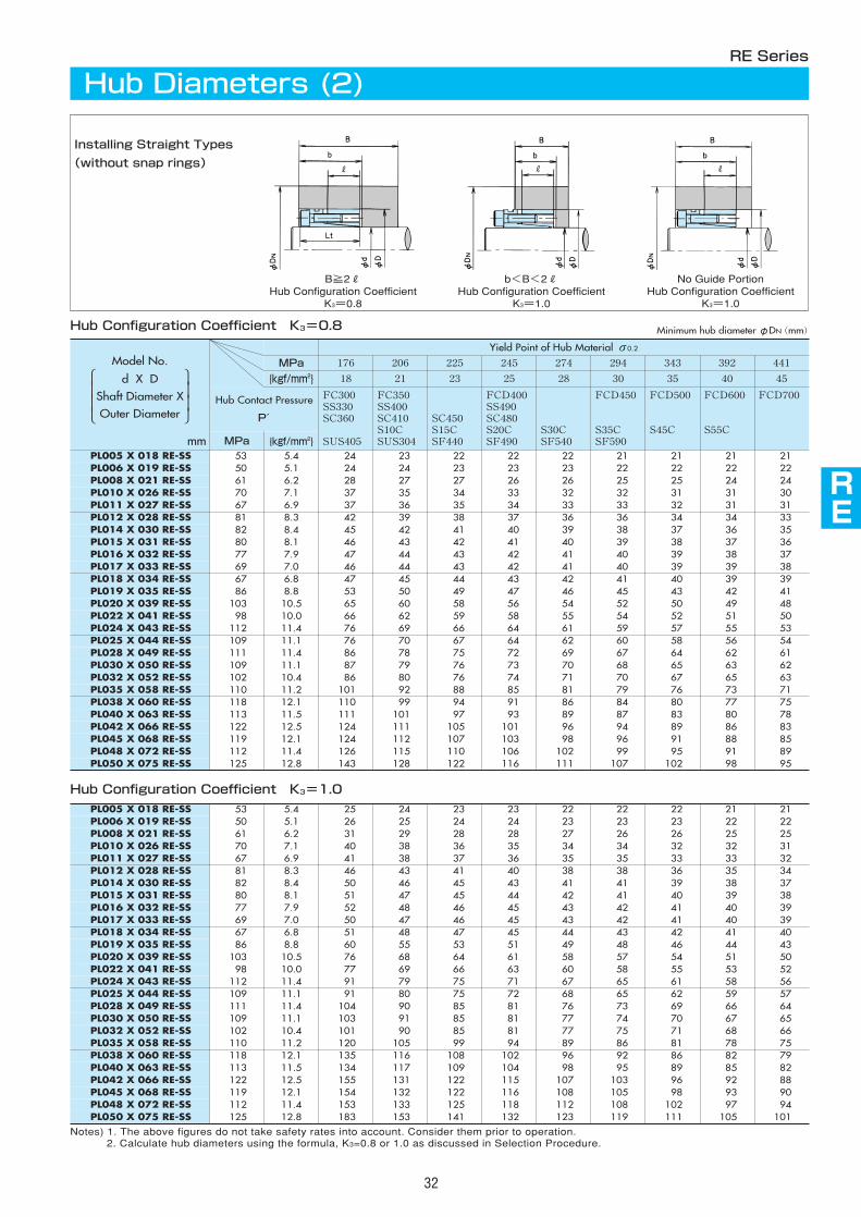
AS
AS
AS
RE
AS
AS
AS
AS
AS
AS
32
MPa 176 206 225 245 274 294 343 392 441
{kgf/mm2} 18 21 23 25 28 30 35 40 45
Hub Contact Pressure
P′
FC300SS330SC360
SUS405
FC350SS400SC410S10CSUS304
SC450S15CSF440
FCD400SS490SC480S20CSF490
S30CSF540
FCD450
S35CSF590
FCD500
S45C
FCD600
S55C
FCD700
MPaPL005 X 018 RE-SS 53 5.4 24 23 22 22 22 21 21 21 21PL006 X 019 RE-SS 50 5.1 24 24 23 23 23 22 22 22 22PL008 X 021 RE-SS 61 6.2 28 27 27 26 26 25 25 24 24PL010 X 026 RE-SS 70 7.1 37 35 34 33 32 32 31 31 30PL011 X 027 RE-SS 67 6.9 37 36 35 34 33 33 32 31 31PL012 X 028 RE-SS 81 8.3 42 39 38 37 36 36 34 34 33PL014 X 030 RE-SS 82 8.4 45 42 41 40 39 38 37 36 35PL015 X 031 RE-SS 80 8.1 46 43 42 41 40 39 38 37 36PL016 X 032 RE-SS 77 7.9 47 44 43 42 41 40 39 38 37PL017 X 033 RE-SS 69 7.0 46 44 43 42 41 40 39 39 38PL018 X 034 RE-SS 67 6.8 47 45 44 43 42 41 40 39 39PL019 X 035 RE-SS 86 8.8 53 50 49 47 46 45 43 42 41PL020 X 039 RE-SS 103 10.5 65 60 58 56 54 52 50 49 48PL022 X 041 RE-SS 98 10.0 66 62 59 58 55 54 52 51 50PL024 X 043 RE-SS 112 11.4 76 69 66 64 61 59 57 55 53PL025 X 044 RE-SS 109 11.1 76 70 67 64 62 60 58 56 54PL028 X 049 RE-SS 111 11.4 86 78 75 72 69 67 64 62 61PL030 X 050 RE-SS 109 11.1 87 79 76 73 70 68 65 63 62PL032 X 052 RE-SS 102 10.4 86 80 76 74 71 70 67 65 63PL035 X 058 RE-SS 110 11.2 101 92 88 85 81 79 76 73 71PL038 X 060 RE-SS 118 12.1 110 99 94 91 86 84 80 77 75PL040 X 063 RE-SS 113 11.5 111 101 97 93 89 87 83 80 78PL042 X 066 RE-SS 122 12.5 124 111 105 101 96 94 89 86 83PL045 X 068 RE-SS 119 12.1 124 112 107 103 98 96 91 88 85PL048 X 072 RE-SS 112 11.4 126 115 110 106 102 99 95 91 89PL050 X 075 RE-SS 125 12.8 143 128 122 116 111 107 102 98 95
PL005 X 018 RE-SS 53 5.4 25 24 23 23 22 22 22 21 21PL006 X 019 RE-SS 50 5.1 26 25 24 24 23 23 23 22 22PL008 X 021 RE-SS 61 6.2 31 29 28 28 27 26 26 25 25PL010 X 026 RE-SS 70 7.1 40 38 36 35 34 34 32 32 31PL011 X 027 RE-SS 67 6.9 41 38 37 36 35 35 33 33 32PL012 X 028 RE-SS 81 8.3 46 43 41 40 38 38 36 35 34PL014 X 030 RE-SS 82 8.4 50 46 45 43 41 41 39 38 37PL015 X 031 RE-SS 80 8.1 51 47 45 44 42 41 40 39 38PL016 X 032 RE-SS 77 7.9 52 48 46 45 43 42 41 40 39PL017 X 033 RE-SS 69 7.0 50 47 46 45 43 42 41 40 39PL018 X 034 RE-SS 67 6.8 51 48 47 45 44 43 42 41 40PL019 X 035 RE-SS 86 8.8 60 55 53 51 49 48 46 44 43PL020 X 039 RE-SS 103 10.5 76 68 64 61 58 57 54 51 50PL022 X 041 RE-SS 98 10.0 77 69 66 63 60 58 55 53 52PL024 X 043 RE-SS 112 11.4 91 79 75 71 67 65 61 58 56PL025 X 044 RE-SS 109 11.1 91 80 75 72 68 65 62 59 57PL028 X 049 RE-SS 111 11.4 104 90 85 81 76 73 69 66 64PL030 X 050 RE-SS 109 11.1 103 91 85 81 77 74 70 67 65PL032 X 052 RE-SS 102 10.4 101 90 85 81 77 75 71 68 66PL035 X 058 RE-SS 110 11.2 120 105 99 94 89 86 81 78 75PL038 X 060 RE-SS 118 12.1 135 116 108 102 96 92 86 82 79PL040 X 063 RE-SS 113 11.5 134 117 109 104 98 95 89 85 82PL042 X 066 RE-SS 122 12.5 155 131 122 115 107 103 96 92 88PL045 X 068 RE-SS 119 12.1 154 132 122 116 108 105 98 93 90PL048 X 072 RE-SS 112 11.4 153 133 125 118 112 108 102 97 94PL050 X 075 RE-SS 125 12.8 183 153 141 132 123 119 111 105 101
Notes) 1. The above figures do not take safety rates into account. Consider them prior to operation.2. Calculate hub diameters using the formula, K3=0.8 or 1.0 as discussed in Selection Procedure.
{kgf/mm2}
RE Series
Hub Diameters (2)
Installing Straight Types
(without snap rings)
Hub Configuration Coefficient K3=0.8
Hub Configuration Coefficient K3=1.0
B≧2RHub Configuration Coefficient
K3=0.8
b<B<2RHub Configuration Coefficient
K3=1.0
No Guide PortionHub Configuration Coefficient
K3=1.0
mm
Minimum hub diameterφDN(mm)
Yield Point of Hub Material σ0.2
Model No.
d X DShaft Diameter XOuter Diameter
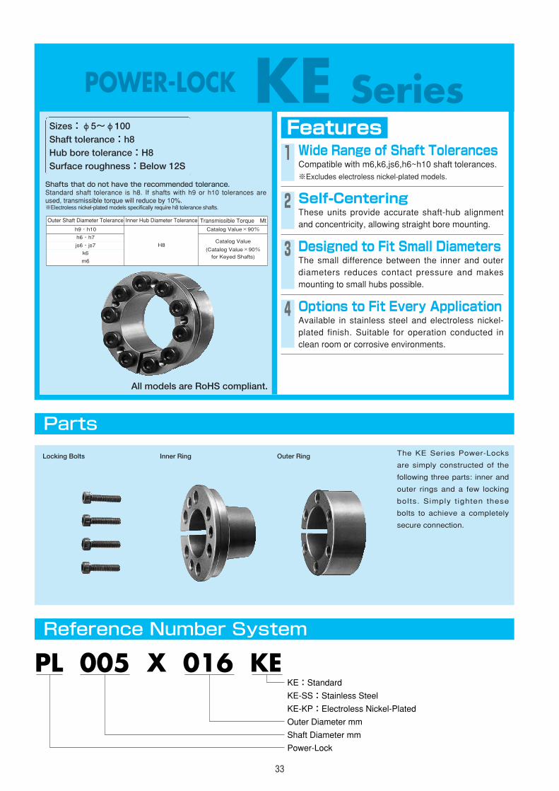
33
POWER-LOCK KE SeriesFeaturesSizes:φ5~φ100
Shaft tolerance:h8Hub bore tolerance:H8Surface roughness:Below 12S
1 Wide Range of Shaft TolerancesCompatible with m6,k6,js6,h6~h10 shaft tolerances. ※Excludes electroless nickel-plated models.
2 Self-CenteringThese units provide accurate shaft-hub alignmentand concentricity, allowing straight bore mounting.
Shafts that do not have the recommended tolerance.Standard shaft tolerance is h8. If shafts with h9 or h10 tolerances areused, transmissible torque will reduce by 10%.※Electroless nickel-plated models specifically require h8 tolerance shafts.
3 Designed to Fit Small DiametersThe small difference between the inner and outerdiameters reduces contact pressure and makesmounting to small hubs possible.
4 Options to Fit Every ApplicationAvailable in stainless steel and electroless nickel-plated finish. Suitable for operation conducted inclean room or corrosive environments.
Parts
Reference Number System
The KE Series Power-Locks
are simply constructed of the
following three parts: inner and
outer rings and a few locking
bolts. Simply t ighten these
bolts to achieve a completely
secure connection.
PL 005 X 016 KE
Shaft Diameter mm
Power-Lock
Outer Diameter mm
KE:Standard
KE-KP:Electroless Nickel-Plated
KE-SS:Stainless Steel
Locking Bolts Inner Ring Outer Ring
Outer Shaft Diameter Tolerance
h9・h10 Catalog Value×90%
Catalog Value
(Catalog Value×90%for Keyed Shafts)
h6・h7
js6・js7
k6
m6
Inner Hub Diameter Tolerance
H8
Transmissible Torque Mt
All models are RoHS compliant.
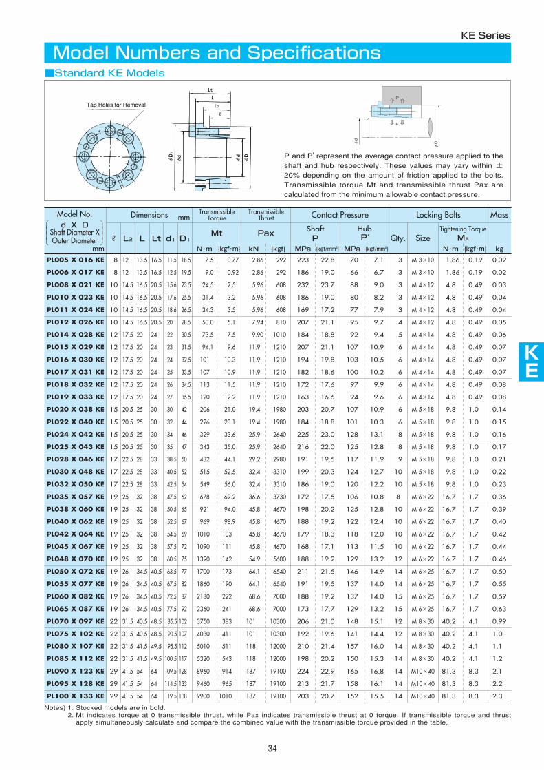
AS
AS
AS
AS
KE
AS
AS
AS
AS
AS
34
Notes) 1. Stocked models are in bold.2. Mt indicates torque at 0 transmissible thrust, while Pax indicates transmissible thrust at 0 torque. If transmissible torque and thrust
apply simultaneously calculate and compare the combined value with the transmissible torque provided in the table.
Dimensions mmTransmissible
TorqueTransmissible
Thrust Contact Pressure Locking Bolts Mass
RMt Pax
ShaftP
HubP′ Qty.
Tightening TorqueMA
PL005 X 016 KE 8 7.5 2.86 223 70 3 1.86 0.02
PL006 X 017 KE 8 9.0 2.86 186 66 3 1.86 0.02
PL008 X 021 KE 10 24.5 5.96 232 88 3 4.8 0.03
PL010 X 023 KE 10 31.4 5.96 186 80 3 4.8 0.04
PL011 X 024 KE 10 34.3 5.96 169 77 3 4.8 0.04
PL012 X 026 KE 10 50.0 7.94 207 95 4 4.8 0.05
PL014 X 028 KE 12 73.5 9.90 184 92 5 4.8 0.06
PL015 X 029 KE 12 94.1 11.9 207 107 6 4.8 0.07
PL016 X 030 KE 12 101 11.9 194 103 6 4.8 0.07
PL017 X 031 KE 12 107 11.9 182 100 6 4.8 0.07
PL018 X 032 KE 12 113 11.9 172 97 6 4.8 0.08
PL019 X 033 KE 12 120 11.9 163 94 6 4.8 0.08
PL020 X 038 KE 15 206 19.4 203 107 6 9.8 0.14
PL022 X 040 KE 15 226 19.4 184 101 6 9.8 0.15
PL024 X 042 KE 15 329 25.9 225 128 8 9.8 0.16
PL025 X 043 KE 15 343 25.9 216 125 8 9.8 0.17
PL028 X 046 KE 17 432 29.2 191 117 9 9.8 0.21
PL030 X 048 KE 17 515 32.4 199 124 10 9.8 0.22
PL032 X 050 KE 17 549 32.4 186 120 10 9.8 0.23
PL035 X 057 KE 19 678 36.6 172 106 8 16.7 0.36
PL038 X 060 KE 19 921 45.8 198 125 10 16.7 0.39
PL040 X 062 KE 19 969 45.8 188 122 10 16.7 0.40
PL042 X 064 KE 19 1010 45.8 179 118 10 16.7 0.42
PL045 X 067 KE 19 1090 45.8 168 113 10 16.7 0.44
PL048 X 070 KE 19 1390 54.9 188 129 12 16.7 0.46
PL050 X 072 KE 19 1700 64.1 211 146 14 16.7 0.50
PL055 X 077 KE 19 1860 64.1 191 137 14 16.7 0.55
PL060 X 082 KE 19 2180 68.6 188 137 15 16.7 0.59
PL065 X 087 KE 19 2360 68.6 173 129 15 16.7 0.63
PL070 X 097 KE 22 3750 101 206 148 12 40.2 0.99
PL075 X 102 KE 22 4030 101 192 141 12 40.2 1.0
PL080 X 107 KE 22 5010 118 210 157 14 40.2 1.1
PL085 X 112 KE 22 5320 118 198 150 14 40.2 1.2
PL090 X 123 KE 29 8960 187 224 165 14 81.3 2.1
PL095 X 128 KE 29 9460 187 213 158 14 81.3 2.2
PL100 X 133 KE 29 9900 187 203 152 14 81.3 2.3
L2 L Lt d1 D1
12 13.5 16.5 11.5 18.5 0.77
12 13.5 16.5 12.5 19.5 0.92
14.5 16.5 20.5 15.6 23.5 2.5
14.5 16.5 20.5 17.6 25.5 3.2
14.5 16.5 20.5 18.6 26.5 3.5
14.5 16.5 20.5 20 28.5 5.1
17.5 20 24 22 30.5 7.5
17.5 20 24 23 31.5 9.6
17.5 20 24 24 32.5 10.3
17.5 20 24 25 33.5 10.9
17.5 20 24 26 34.5 11.5
17.5 20 24 27 35.5 12.2
20.5 25 30 30 42 21.0
20.5 25 30 32 44 23.1
20.5 25 30 34 46 33.6
20.5 25 30 35 47 35.0
22.5 28 33 38.5 50 44.1
22.5 28 33 40.5 52 52.5
22.5 28 33 42.5 54 56.0
25 32 38 47.5 62 69.2
25 32 38 50.5 65 94.0
25 32 38 52.5 67 98.9
25 32 38 54.5 69 103
25 32 38 57.5 72 111
25 32 38 60.5 75 142
26 34.5 40.5 63.5 77 173
26 34.5 40.5 67.5 82 190
26 34.5 40.5 72.5 87 222
26 34.5 40.5 77.5 92 241
31.5 40.5 48.5 85.5 102 383
31.5 40.5 48.5 90.5 107 411
31.5 41.5 49.5 95.5 112 511
31.5 41.5 49.5 100.5 117 543
41.5 54 64 109.5 128 914
41.5 54 64 114.5 133 965
41.5 54 64 119.5 138 1010
292 22.8 7.1
292 19.0 6.7
608 23.7 9.0
608 19.0 8.2
608 17.2 7.9
810 21.1 9.7
1010 18.8 9.4
1210 21.1 10.9
1210 19.8 10.5
1210 18.6 10.2
1210 17.6 9.9
1210 16.6 9.6
1980 20.7 10.9
1980 18.8 10.3
2640 23.0 13.1
2640 22.0 12.8
2980 19.5 11.9
3310 20.3 12.7
3310 19.0 12.2
3730 17.5 10.8
4670 20.2 12.8
4670 19.2 12.4
4670 18.3 12.0
4670 17.1 11.5
5600 19.2 13.2
6540 21.5 14.9
6540 19.5 14.0
7000 19.2 14.0
7000 17.7 13.2
10300 21.0 15.1
10300 19.6 14.4
12000 21.4 16.0
12000 20.2 15.3
19100 22.9 16.8
19100 21.7 16.1
19100 20.7 15.5
Size
M 3×10 0.19
M 3×10 0.19
M 4×12 0.49
M 4×12 0.49
M 4×12 0.49
M 4×12 0.49
M 4×14 0.49
M 4×14 0.49
M 4×14 0.49
M 4×14 0.49
M 4×14 0.49
M 4×14 0.49
M 5×18 1.0
M 5×18 1.0
M 5×18 1.0
M 5×18 1.0
M 5×18 1.0
M 5×18 1.0
M 5×18 1.0
M 6×22 1.7
M 6×22 1.7
M 6×22 1.7
M 6×22 1.7
M 6×22 1.7
M 6×22 1.7
M 6×25 1.7
M 6×25 1.7
M 6×25 1.7
M 6×25 1.7
M 8×30 4.1
M 8×30 4.1
M 8×30 4.1
M 8×30 4.1
M10×40 8.3
M10×40 8.3
M10×40 8.3
N・m {kgf・m} kN {kgf} MPa {kgf/mm2} MPa {kgf/mm2} N・m {kgf・m} kg
KE Series
Model Numbers and Specifications
Tap Holes for Removal
P and P' represent the average contact pressure applied to theshaft and hub respectively. These values may vary within ±20% depending on the amount of friction applied to the bolts.Transmissible torque Mt and transmissible thrust Pax arecalculated from the minimum allowable contact pressure.
P
P'
φd
φD
mm
■Standard KE Models
Model No.d X D
Shaft Diameter XOuter Diameter
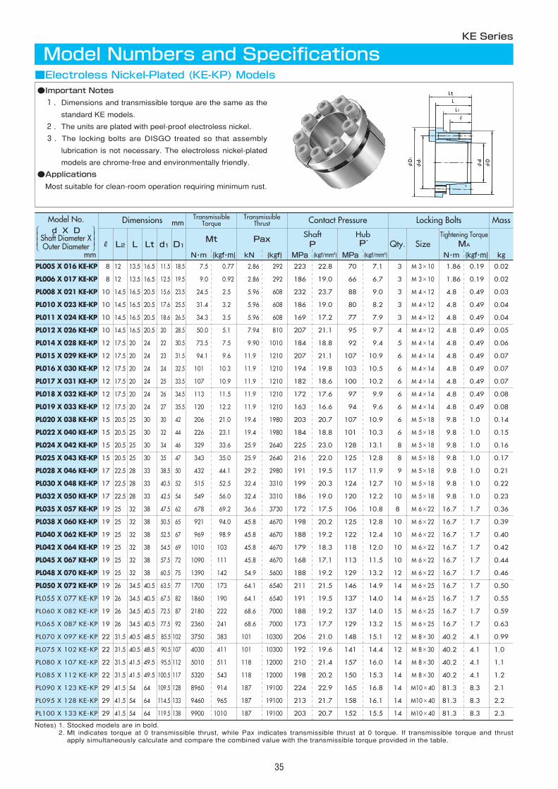
35
■Electroless Nickel-Plated (KE-KP) Models
KE Series
Model Numbers and Specifications
●Important Notes
1.Dimensions and transmissible torque are the same as the
standard KE models.
2.The units are plated with peel-proof electroless nickel.
3.The locking bolts are DISGO treated so that assembly
lubrication is not necessary. The electroless nickel-plated
models are chrome-free and environmentally friendly.
●Applications
Most suitable for clean-room operation requiring minimum rust.
Notes) 1. Stocked models are in bold.2. Mt indicates torque at 0 transmissible thrust, while Pax indicates transmissible thrust at 0 torque. If transmissible torque and thrust
apply simultaneously calculate and compare the combined value with the transmissible torque provided in the table.
Dimensions mmTransmissible
TorqueTransmissible
Thrust Contact Pressure Locking Bolts Mass
RMt Pax
ShaftP
HubP′ Qty.
Tightening TorqueMA
PL005 X 016 KE-KP 8 7.5 2.86 223 70 3 1.86 0.02
PL006 X 017 KE-KP 8 9.0 2.86 186 66 3 1.86 0.02
PL008 X 021 KE-KP 10 24.5 5.96 232 88 3 4.8 0.03
PL010 X 023 KE-KP 10 31.4 5.96 186 80 3 4.8 0.04
PL011 X 024 KE-KP 10 34.3 5.96 169 77 3 4.8 0.04
PL012 X 026 KE-KP 10 50.0 7.94 207 95 4 4.8 0.05
PL014 X 028 KE-KP 12 73.5 9.90 184 92 5 4.8 0.06
PL015 X 029 KE-KP 12 94.1 11.9 207 107 6 4.8 0.07
PL016 X 030 KE-KP 12 101 11.9 194 103 6 4.8 0.07
PL017 X 031 KE-KP 12 107 11.9 182 100 6 4.8 0.07
PL018 X 032 KE-KP 12 113 11.9 172 97 6 4.8 0.08
PL019 X 033 KE-KP 12 120 11.9 163 94 6 4.8 0.08
PL020 X 038 KE-KP 15 206 19.4 203 107 6 9.8 0.14
PL022 X 040 KE-KP 15 226 19.4 184 101 6 9.8 0.15
PL024 X 042 KE-KP 15 329 25.9 225 128 8 9.8 0.16
PL025 X 043 KE-KP 15 343 25.9 216 125 8 9.8 0.17
PL028 X 046 KE-KP 17 432 29.2 191 117 9 9.8 0.21
PL030 X 048 KE-KP 17 515 32.4 199 124 10 9.8 0.22
PL032 X 050 KE-KP 17 549 32.4 186 120 10 9.8 0.23
PL035 X 057 KE-KP 19 678 36.6 172 106 8 16.7 0.36
PL038 X 060 KE-KP 19 921 45.8 198 125 10 16.7 0.39
PL040 X 062 KE-KP 19 969 45.8 188 122 10 16.7 0.40
PL042 X 064 KE-KP 19 1010 45.8 179 118 10 16.7 0.42
PL045 X 067 KE-KP 19 1090 45.8 168 113 10 16.7 0.44
PL048 X 070 KE-KP 19 1390 54.9 188 129 12 16.7 0.46
PL050 X 072 KE-KP 19 1700 64.1 211 146 14 16.7 0.50
PL055 X 077 KE-KP 19 1860 64.1 191 137 14 16.7 0.55
PL060 X 082 KE-KP 19 2180 68.6 188 137 15 16.7 0.59
PL065 X 087 KE-KP 19 2360 68.6 173 129 15 16.7 0.63
PL070 X 097 KE-KP 22 3750 101 206 148 12 40.2 0.99
PL075 X 102 KE-KP 22 4030 101 192 141 12 40.2 1.0
PL080 X 107 KE-KP 22 5010 118 210 157 14 40.2 1.1
PL085 X 112 KE-KP 22 5320 118 198 150 14 40.2 1.2
PL090 X 123 KE-KP 29 8960 187 224 165 14 81.3 2.1
PL095 X 128 KE-KP 29 9460 187 213 158 14 81.3 2.2
PL100 X 133 KE-KP 29 9900 187 203 152 14 81.3 2.3
L2 L Lt d1 D1
12 13.5 16.5 11.5 18.5 0.77
12 13.5 16.5 12.5 19.5 0.92
14.5 16.5 20.5 15.6 23.5 2.5
14.5 16.5 20.5 17.6 25.5 3.2
14.5 16.5 20.5 18.6 26.5 3.5
14.5 16.5 20.5 20 28.5 5.1
17.5 20 24 22 30.5 7.5
17.5 20 24 23 31.5 9.6
17.5 20 24 24 32.5 10.3
17.5 20 24 25 33.5 10.9
17.5 20 24 26 34.5 11.5
17.5 20 24 27 35.5 12.2
20.5 25 30 30 42 21.0
20.5 25 30 32 44 23.1
20.5 25 30 34 46 33.6
20.5 25 30 35 47 35.0
22.5 28 33 38.5 50 44.1
22.5 28 33 40.5 52 52.5
22.5 28 33 42.5 54 56.0
25 32 38 47.5 62 69.2
25 32 38 50.5 65 94.0
25 32 38 52.5 67 98.9
25 32 38 54.5 69 103
25 32 38 57.5 72 111
25 32 38 60.5 75 142
26 34.5 40.5 63.5 77 173
26 34.5 40.5 67.5 82 190
26 34.5 40.5 72.5 87 222
26 34.5 40.5 77.5 92 241
31.5 40.5 48.5 85.5 102 383
31.5 40.5 48.5 90.5 107 411
31.5 41.5 49.5 95.5 112 511
31.5 41.5 49.5 100.5 117 543
41.5 54 64 109.5 128 914
41.5 54 64 114.5 133 965
41.5 54 64 119.5 138 1010
292 22.8 7.1
292 19.0 6.7
608 23.7 9.0
608 19.0 8.2
608 17.2 7.9
810 21.1 9.7
1010 18.8 9.4
1210 21.1 10.9
1210 19.8 10.5
1210 18.6 10.2
1210 17.6 9.9
1210 16.6 9.6
1980 20.7 10.9
1980 18.8 10.3
2640 23.0 13.1
2640 22.0 12.8
2980 19.5 11.9
3310 20.3 12.7
3310 19.0 12.2
3730 17.5 10.8
4670 20.2 12.8
4670 19.2 12.4
4670 18.3 12.0
4670 17.1 11.5
5600 19.2 13.2
6540 21.5 14.9
6540 19.5 14.0
7000 19.2 14.0
7000 17.7 13.2
10300 21.0 15.1
10300 19.6 14.4
12000 21.4 16.0
12000 20.2 15.3
19100 22.9 16.8
19100 21.7 16.1
19100 20.7 15.5
Size
M 3×10 0.19
M 3×10 0.19
M 4×12 0.49
M 4×12 0.49
M 4×12 0.49
M 4×12 0.49
M 4×14 0.49
M 4×14 0.49
M 4×14 0.49
M 4×14 0.49
M 4×14 0.49
M 4×14 0.49
M 5×18 1.0
M 5×18 1.0
M 5×18 1.0
M 5×18 1.0
M 5×18 1.0
M 5×18 1.0
M 5×18 1.0
M 6×22 1.7
M 6×22 1.7
M 6×22 1.7
M 6×22 1.7
M 6×22 1.7
M 6×22 1.7
M 6×25 1.7
M 6×25 1.7
M 6×25 1.7
M 6×25 1.7
M 8×30 4.1
M 8×30 4.1
M 8×30 4.1
M 8×30 4.1
M10×40 8.3
M10×40 8.3
M10×40 8.3
N・m {kgf・m} kN {kgf} MPa {kgf/mm2} MPa {kgf/mm2} N・m {kgf・m} kgmm
Model No.d X D
Shaft Diameter XOuter Diameter

Dimensions TransmissibleTorque
TransmissibleThrust Contact Pressure Locking Bolts Mass
RMt Pax
ShaftP
HubP′ Qty.
Tightening TorqueMA
PL005 X 016 KE-SS 8 5.0 1.89 111 35 3 0.9 0.02
PL006 X 017 KE-SS 8 6.0 1.89 92 33 3 0.9 0.02
PL008 X 021 KE-SS 10 14.2 3.37 98 38 3 2.2 0.03
PL010 X 023 KE-SS 10 17.7 3.37 79 34 3 2.2 0.04
PL011 X 024 KE-SS 10 19.6 3.37 72 33 3 2.2 0.04
PL012 X 026 KE-SS 10 28.4 4.49 88 40 4 2.2 0.05
PL014 X 028 KE-SS 12 41.6 5.61 78 39 5 2.2 0.06
PL015 X 029 KE-SS 12 44.5 5.61 73 38 5 2.2 0.07
PL016 X 030 KE-SS 12 47.4 5.61 68 36 5 2.2 0.07
PL017 X 031 KE-SS 12 60.6 6.73 77 42 6 2.2 0.07
PL018 X 032 KE-SS 12 64.1 6.73 73 41 6 2.2 0.08
PL019 X 033 KE-SS 12 67.7 6.73 69 40 6 2.2 0.08
PL020 X 038 KE-SS 15 141 13.4 104 55 6 5.3 0.14
PL022 X 040 KE-SS 15 156 13.4 95 52 6 5.3 0.15
PL024 X 042 KE-SS 15 170 13.4 87 50 6 5.3 0.16
PL025 X 043 KE-SS 15 177 13.4 83 48 6 5.3 0.17
PL028 X 046 KE-SS 17 264 17.8 88 53 8 5.3 0.21
PL030 X 048 KE-SS 17 283 17.8 82 51 8 5.3 0.22
PL032 X 050 KE-SS 17 302 17.8 77 49 8 5.3 0.23
PL035 X 057 KE-SS 19 351 18.9 67 41 6 9.0 0.36
PL038 X 060 KE-SS 19 508 25.2 82 52 8 9.0 0.39
PL040 X 062 KE-SS 19 535 25.2 78 50 8 9.0 0.40
PL042 X 064 KE-SS 19 561 25.2 74 49 8 9.0 0.42
PL045 X 067 KE-SS 19 602 25.2 69 46 8 9.0 0.44
PL048 X 070 KE-SS 19 722 28.4 73 50 9 9.0 0.46
PL050 X 072 KE-SS 19 836 31.6 78 54 10 9.0 0.50
L2 L Lt d1 D1
12 13.5 16.5 11.5 18.5 0.51
12 13.5 16.5 12.5 19.5 0.61
14.5 16.5 20.5 15.6 23.5 1.5
14.5 16.5 20.5 17.6 25.5 1.8
14.5 16.5 20.5 18.6 26.5 2.0
14.5 16.5 20.5 20 28.5 2.9
17.5 20 24 22 30.5 4.2
17.5 20 24 23 31.5 4.5
17.5 20 24 24 32.5 4.8
17.5 20 24 25 33.5 6.2
17.5 20 24 26 34.5 6.5
17.5 20 24 27 35.5 6.9
20.5 25 30 30 42 14.4
20.5 25 30 32 44 15.9
20.5 25 30 34 46 17.3
20.5 25 30 35 47 18.0
22.5 28 33 38.5 50 26.9
22.5 28 33 40.5 52 28.9
22.5 28 33 42.5 54 30.8
25 32 38 47.5 62 35.8
25 32 38 50.5 65 51.8
25 32 38 52.5 67 54.6
25 32 38 54.5 69 57.3
25 32 38 57.5 72 61.4
25 32 38 60.5 75 73.7
26 34.5 40.5 63.5 77 85.3
193 11.3 3.5
193 9.4 3.3
344 10.1 3.8
344 8.0 3.5
344 7.3 3.4
458 8.9 4.1
573 8.0 4.0
573 7.4 3.9
573 7.0 3.7
687 7.9 4.3
687 7.4 4.2
687 7.1 4.1
1363 10.6 5.6
1363 9.7 5.3
1363 8.9 5.1
1363 8.5 4.9
1818 8.9 5.4
1818 8.3 5.2
1818 7.8 5.0
1932 6.8 4.2
2577 8.4 5.3
2577 7.9 5.1
2577 7.6 5.0
2577 7.1 4.7
2899 7.4 5.1
3221 7.9 5.5
Size
M 3×10 0.092
M 3×10 0.092
M 4×14 0.22
M 4×14 0.22
M 4×14 0.22
M 4×14 0.22
M 4×14 0.22
M 4×14 0.22
M 4×14 0.22
M 4×14 0.22
M 4×14 0.22
M 4×14 0.22
M 5×20 0.54
M 5×20 0.54
M 5×20 0.54
M 5×20 0.54
M 5×20 0.54
M 5×20 0.54
M 5×20 0.54
M 6×25 0.92
M 6×25 0.92
M 6×25 0.92
M 6×25 0.92
M 6×25 0.92
M 6×25 0.92
M 6×25 0.92
N・m {kgf・m} kN {kgf} MPa {kgf/mm2} MPa {kgf/mm2} N・m {kgf・m}
KE
36
■Stainless Steel (KE-SS) Models
KE Series
Model Numbers and Specifications
●Notes
1.The main unit is made of highly anticorrosive austenite
stainless steel.
2.Locking bolts are lubricated so that no addit ional
lubrication is necessary during assembly.
●Applications
Most suitable for clean-room operation requiring minimum rust.
Notes) 1. All models are in stock.2. Mt indicates torque at 0 transmissible thrust, while Pax indicates transmissible thrust at 0 torque. If transmissible torque and thrust
apply simultaneously calculate and compare the combined value with the transmissible torque provided in the table.
mm
kgmm kg
Model No.d X D
Shaft Diameter XOuter Diameter
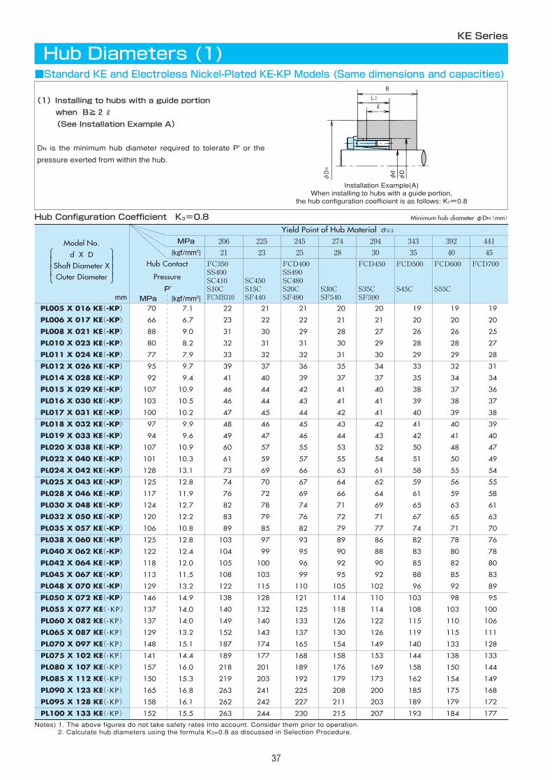
37
Notes) 1. The above figures do not take safety rates into account. Consider them prior to operation.2. Calculate hub diameters using the formula K3=0.8 as discussed in Selection Procedure.
MPa 206 225 245 274 294 392 441
{kgf/mm2} 21 23 25 28 30 40 45
Hub Contact
Pressure
P′
FC350SS400SC410S10CFCMB310
SC450S15CSF440
FCD400SS490SC480S20CSF490
S30CSF540
FCD450
S35CSF590
FCD600
S55C
FCD700
MPa {kgf/mm2}PL005 X 016 KE(-KP) 70 7.1 22 21 21 20 20 19 19
PL006 X 017 KE(-KP) 66 6.7 23 22 22 21 21 20 20
PL008 X 021 KE(-KP) 88 9.0 31 30 29 28 27 26 25
PL010 X 023 KE(-KP) 80 8.2 32 31 31 30 29 28 27
PL011 X 024 KE(-KP) 77 7.9 33 32 32 31 30 29 28
PL012 X 026 KE(-KP) 95 9.7 39 37 36 35 34 32 31
PL014 X 028 KE(-KP) 92 9.4 41 40 39 37 37 34 34
PL015 X 029 KE(-KP) 107 10.9 46 44 42 41 40 37 36
PL016 X 030 KE(-KP) 103 10.5 46 44 43 41 41 38 37
PL017 X 031 KE(-KP) 100 10.2 47 45 44 42 41 39 38
PL018 X 032 KE(-KP) 97 9.9 48 46 45 43 42 40 39
PL019 X 033 KE(-KP) 94 9.6 49 47 46 44 43 41 40
PL020 X 038 KE(-KP) 107 10.9 60 57 55 53 52 48 47
PL022 X 040 KE(-KP) 101 10.3 61 59 57 55 54 50 49
PL024 X 042 KE(-KP) 128 13.1 73 69 66 63 61 55 54
PL025 X 043 KE(-KP) 125 12.8 74 70 67 64 62 56 55
PL028 X 046 KE(-KP) 117 11.9 76 72 69 66 64 59 58
PL030 X 048 KE(-KP) 124 12.7 82 78 74 71 69 63 61
PL032 X 050 KE(-KP) 120 12.2 83 79 76 72 71 65 63
PL035 X 057 KE(-KP) 106 10.8 89 85 82 79 77 71 70
PL038 X 060 KE(-KP) 125 12.8 103 97 93 89 86 78 76
PL040 X 062 KE(-KP) 122 12.4 104 99 95 90 88 80 78
PL042 X 064 KE(-KP) 118 12.0 105 100 96 92 90 82 80
PL045 X 067 KE(-KP) 113 11.5 108 103 99 95 92 85 83
PL048 X 070 KE(-KP) 129 13.2 122 115 110 105 102 92 89
PL050 X 072 KE(-KP) 146 14.9 138 128 121 114 110 98 95
PL055 X 077 KE( -KP) 137 14.0 140 132 125 118 114 103 100
PL060 X 082 KE(-KP) 137 14.0 149 140 133 126 122 110 106
PL065 X 087 KE(-KP) 129 13.2 152 143 137 130 126 115 111
PL070 X 097 KE(-KP) 148 15.1 187 174 165 154 149 133 128
PL075 X 102 KE(-KP) 141 14.4 189 177 168 158 153 138 133
PL080 X 107 KE(-KP) 157 16.0 218 201 189 176 169 150 144
PL085 X 112 KE(-KP) 150 15.3 219 203 192 179 173 154 149
PL090 X 123 KE(-KP) 165 16.8 263 241 225 208 200 175 168
PL095 X 128 KE(-KP) 158 16.1 262 242 227 211 203 179 172
PL100 X 133 KE(-KP) 152 15.5 263 244 230 215 207 184 177
343
35
FCD500
S45C
19
20
26
28
29
33
35
38
39
40
41
42
50
51
58
59
61
65
67
74
82
83
85
88
96
103
108
115
119
140
144
158
162
185
189
193
Yield Point of Hub Material σ0.2
(1)Installing to hubs with a guide portion
when B≧2R
(See Installation Example A)
DN is the minimum hub diameter required to tolerate P' or the
pressure exerted from within the hub.
KE Series
Hub Diameters (1)
Hub Configuration Coefficient K3=0.8
Installation Example(A)When installing to hubs with a guide portion,
the hub configuration coefficient is as follows: K3=0.8
mm
■Standard KE and Electroless Nickel-Plated KE-KP Models (Same dimensions and capacities)
Minimum hub diameterφDN(mm)
Model No.
d X DShaft Diameter XOuter Diameter
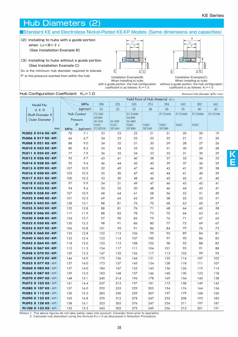
KE
38
Notes) 1. The above figures do not take safety rates into account. Consider them prior to operation.2. Calculate hub diameters using the formula K3=1.0 as discussed in Selection Procedure.
MPa 206 225 245 274 294 392 441
{kgf/mm2} 21 23 25 28 30 40 45
Hub Contact
Pressure
P′
FC350SS400SC410S10CFCMB310
SC450S15CSF440
FCD400SS490SC480S20CSF490
S30CSF540
FCD450
S35CSF590
FCD600
S55C
FCD700
MPa {kgf/mm2}PL005 X 016 KE(-KP) 70 7.1 23 23 22 21 21 20 19
PL006 X 017 KE(-KP) 66 6.7 24 23 23 22 22 21 20
PL008 X 021 KE(-KP) 88 9.0 34 32 31 30 29 27 26
PL010 X 023 KE(-KP) 80 8.2 35 34 33 32 31 29 28
PL011 X 024 KE(-KP) 77 7.9 36 35 34 33 32 30 29
PL012 X 026 KE(-KP) 95 9.7 43 41 40 38 37 34 33
PL014 X 028 KE(-KP) 92 9.4 46 44 42 40 39 36 35
PL015 X 029 KE(-KP) 107 10.9 52 49 47 44 43 39 38
PL016 X 030 KE(-KP) 103 10.5 52 50 47 45 44 40 39
PL017 X 031 KE(-KP) 100 10.2 53 50 48 46 45 41 40
PL018 X 032 KE(-KP) 97 9.9 54 51 49 47 46 42 41
PL019 X 033 KE(-KP) 94 9.6 55 52 50 48 46 43 41
PL020 X 038 KE(-KP) 107 10.9 68 64 61 58 56 51 49
PL022 X 040 KE(-KP) 101 10.3 69 65 62 59 58 53 51
PL024 X 042 KE(-KP) 128 13.1 88 81 76 70 68 60 57
PL025 X 043 KE(-KP) 125 12.8 88 81 76 71 68 60 58
PL028 X 046 KE(-KP) 117 11.9 88 82 78 73 70 63 61
PL030 X 048 KE(-KP) 124 12.7 97 90 85 79 76 67 65
PL032 X 050 KE(-KP) 120 12.2 98 91 86 80 77 69 67
PL035 X 057 KE(-KP) 106 10.8 101 95 91 86 84 76 73
PL038 X 060 KE(-KP) 125 12.8 122 113 106 99 95 84 81
PL040 X 062 KE(-KP) 122 12.4 123 114 107 100 97 86 83
PL042 X 064 KE(-KP) 118 12.0 123 115 108 102 98 88 85
PL045 X 067 KE(-KP) 113 11.5 124 117 111 104 101 91 88
PL048 X 070 KE(-KP) 129 13.2 147 135 126 117 113 99 95
PL050 X 072 KE(-KP) 146 14.9 175 156 144 131 125 107 102
PL055 X 077 KE(-KP) 137 14.0 173 157 145 134 128 111 107
PL060 X 082 KE(-KP) 137 14.0 184 167 155 143 136 119 114
PL065 X 087 KE(-KP) 129 13.2 183 168 157 146 140 123 118
PL070 X 097 KE(-KP) 148 15.1 240 214 196 178 169 145 138
PL075 X 102 KE(-KP) 141 14.4 237 213 197 181 173 149 143
PL080 X 107 KE(-KP) 157 16.0 292 253 229 205 194 164 156
PL085 X 112 KE(-KP) 150 15.3 283 250 229 207 197 168 160
PL090 X 123 KE(-KP) 165 16.8 370 312 278 247 232 193 183
PL095 X 128 KE(-KP) 158 16.1 353 305 276 247 234 197 187
PL100 X 133 KE(-KP) 152 15.5 343 302 275 249 236 201 191
343
35
FCD500
S45C
20
21
28
30
31
35
37
41
41
42
43
44
53
55
63
64
66
71
72
79
89
90
92
95
105
114
118
126
130
154
158
176
179
208
211
215
Yield Point of Hub Material σ0.2
KE Series
Hub Diameters (2)
Hub Configuration Coefficient K3=1.0
(2)Installing to hubs with a guide portion
when L2<B<2R
(See Installation Example B)
(3)Installing to hubs without a guide portion
(See Installation Example C)
DN is the minimum hub diameter required to tolerate
P' or the pressure exerted from within the hub.
mm
■Standard KE and Electroless Nickel-Plated KE-KP Models (Same dimensions and capacities)
Minimum hub diameterφDN(mm)
Model No.
d X DShaft Diameter XOuter Diameter
Installation Example(B)When installing to hubs
with a guide portion, the hub configurationcoefficient is as follows: K3=1.0
Installation Example(C)When installing to hubs
without a guide portion, the hub configurationcoefficient is as follows: K3=1.0
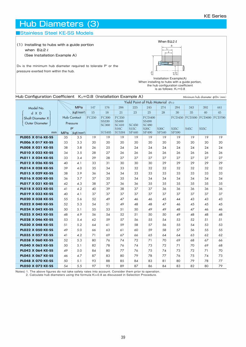
39
Notes) 1. The above figures do not take safety rates into account. Consider them prior to operation.2. Calculate hub diameters using the formula K3=0.8 as discussed in Selection Procedure.
MPa 147 176 206 225 245 274 294 392 441
{kgf/mm2} 15 18 21 23 25 28 30 40 45
Hub Contact
Pressure
P′
FC250 FC300SS330SC360
SUS405
FC350SS400SC410S10CSUS304
SC450S15CSF440
FCD400SS490SC480S20CSF490
S30CSF540
FCD450
S35CSF590
FCD600
S55C
FCD700
MPa {kgf/mm2}PL005 X 016 KE-SS 35 3.5 19 19 19 19 19 19 19 19 19
PL006 X 017 KE-SS 33 3.3 20 20 20 20 20 20 20 20 20
PL008 X 021 KE-SS 38 3.8 26 25 24 24 24 24 24 24 24
PL010 X 023 KE-SS 34 3.5 28 27 26 26 26 26 26 26 26
PL011 X 024 KE-SS 33 3.4 29 28 27 27 27 27 27 27 27
PL012 X 026 KE-SS 40 4.1 33 31 30 30 30 29 29 29 29
PL014 X 028 KE-SS 39 4.0 35 34 33 32 32 32 32 32 32
PL015 X 029 KE-SS 38 3.9 36 34 34 33 33 33 33 33 33
PL016 X 030 KE-SS 36 3.7 37 35 35 34 34 34 34 34 34
PL017 X 031 KE-SS 42 4.3 38 37 36 36 35 35 35 35 35
PL018 X 032 KE-SS 41 4.2 40 39 38 37 37 36 36 36 36
PL019 X 033 KE-SS 40 4.1 37 37 37 37 37 37 37 37 37
PL020 X 038 KE-SS 55 5.6 52 49 47 46 46 45 44 43 43
PL022 X 040 KE-SS 52 5.3 54 51 49 48 48 47 46 45 45
PL024 X 042 KE-SS 50 5.1 55 53 51 50 49 49 48 46 46
PL025 X 043 KE-SS 48 4.9 56 54 52 51 50 50 49 48 48
PL028 X 046 KE-SS 53 5.4 62 59 57 56 55 54 53 51 51
PL030 X 048 KE-SS 51 5.2 64 61 59 58 57 56 55 53 53
PL032 X 050 KE-SS 49 5.0 66 63 61 60 59 58 57 55 55
PL035 X 057 KE-SS 41 4.2 71 69 67 66 65 64 64 62 62
PL038 X 060 KE-SS 52 5.3 80 76 74 72 71 70 69 67 66
PL040 X 062 KE-SS 50 5.1 82 78 76 74 73 72 71 69 68
PL042 X 064 KE-SS 49 5.0 84 80 77 76 75 74 73 71 70
PL045 X 067 KE-SS 46 4.7 87 83 80 79 78 77 76 74 73
PL048 X 070 KE-SS 50 5.1 93 88 85 84 83 81 80 78 77
PL050 X 072 KE-SS 54 5.5 97 93 89 87 86 84 83 80 79
343
35
FCD500
S45C
19
20
24
26
27
29
32
33
34
35
36
37
43
45
47
48
52
54
56
63
68
70
72
75
79
82
Yield Point of Hub Material σ0.2
(1)Installing to hubs with a guide portion
when B≧2R
(See Installation Example A)
DN is the minimum hub diameter required to tolerate P' or the
pressure exerted from within the hub.
KE Series
Hub Diameters (3)
When B≧2R
φDN
φdφD
BL2
R
Hub Configuration Coefficient K3=0.8(Installation Example A)
Installation Example(A)When installing to hubs with a guide portion,
the hub configuration coefficientis as follows: K3=0.8
mm
■Stainless Steel KE-SS Models
Minimum hub diameterφDN(mm)
Model No.
d X DShaft Diameter XOuter Diameter
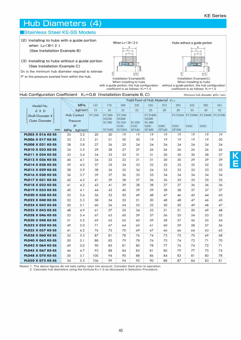
MPa 147 176 206 225 245 274 294 392 441
{kgf/mm2} 15 18 21 23 25 28 30 40 45
Hub Contact
Pressure
P′
FC250 FC300SS330SC360
SUS405
FC350SS400SC410S10CSUS304
SC450S15CSF440
FCD400SS490SC480S20CSF490
S30CSF540
FCD450
S35CSF590
FCD600
S55C
FCD700
MPa {kgf/mm2}PL005 X 016 KE-SS 35 3.5 20 20 19 19 19 19 19 19 19
PL006 X 017 KE-SS 33 3.3 21 21 20 20 19 19 19 19 20
PL008 X 021 KE-SS 38 3.8 27 26 25 24 24 24 24 24 24
PL010 X 023 KE-SS 34 3.5 29 28 27 27 26 26 26 26 26
PL011 X 024 KE-SS 33 3.4 34 33 32 31 31 30 30 28 27
PL012 X 026 KE-SS 40 4.1 34 33 32 31 31 30 30 29 29
PL014 X 028 KE-SS 39 4.0 37 35 34 33 33 32 32 32 32
PL015 X 029 KE-SS 38 3.9 38 36 35 34 34 33 33 33 33
PL016 X 030 KE-SS 36 3.7 39 37 36 35 35 34 34 34 34
PL017 X 031 KE-SS 42 4.3 41 39 38 37 36 36 35 35 35
PL018 X 032 KE-SS 41 4.2 43 41 39 38 38 37 37 36 36
PL019 X 033 KE-SS 40 4.1 44 42 40 39 39 38 38 37 37
PL020 X 038 KE-SS 55 5.6 56 52 50 49 48 47 46 44 43
PL022 X 040 KE-SS 52 5.3 58 54 52 51 50 48 48 46 45
PL024 X 042 KE-SS 50 5.1 60 56 54 53 52 50 50 48 47
PL025 X 043 KE-SS 48 4.9 61 57 55 54 53 51 51 49 48
PL028 X 046 KE-SS 53 5.4 67 63 60 59 57 56 55 53 52
PL030 X 048 KE-SS 51 5.2 69 65 62 60 59 58 57 55 54
PL032 X 050 KE-SS 49 5.0 71 67 64 62 61 60 59 57 56
PL035 X 057 KE-SS 41 4.2 76 72 70 69 67 66 66 63 63
PL038 X 060 KE-SS 52 5.3 87 81 78 76 74 73 72 69 68
PL040 X 062 KE-SS 50 5.1 88 83 79 78 76 75 74 71 70
PL042 X 064 KE-SS 49 5.0 90 85 81 80 78 77 76 72 71
PL045 X 067 KE-SS 46 4.7 93 88 84 83 81 80 79 75 74
PL048 X 070 KE-SS 50 5.1 100 94 90 88 86 84 83 80 78
PL050 X 072 KE-SS 54 5.5 106 99 94 92 90 88 87 83 81
343
35
FCD500
S45C
19
19
24
26
30
29
32
33
34
35
36
37
45
47
49
50
54
56
58
64
70
72
74
77
81
84
Yield Point of Hub Material σ0.2
KE
40
Notes) 1. The above figures do not take safety rates into account. Consider them prior to operation.2. Calculate hub diameters using the formula K3=1.0 as discussed in Selection Procedure.
KE Series
Hub Diameters (4)
When L2<B<2R
φDN
BL2
R
φdφD
Hub Configuration Coefficient K3=0.8(Installation Example B, C)
(2)Installing to hubs with a guide portion
when L2<B<2R
(See Installation Example B)
(3)Installing to hubs without a guide portion
(See Installation Example C)
DN is the minimum hub diameter required to tolerate
P' or the pressure exerted from within the hub.
mm
■Stainless Steel KE-SS Models
Minimum hub diameterφDN(mm)
Hubs without a guide portion
φDN
BL2
R
φdφD
Model No.
d X DShaft Diameter XOuter Diameter
Installation Example(B)When installing to hubs
with a guide portion, the hub configurationcoefficient is as follows: K3=1.0
Installation Example(C)When installing to hubs
without a guide portion, the hub configurationcoefficient is as follows: K3=1.0
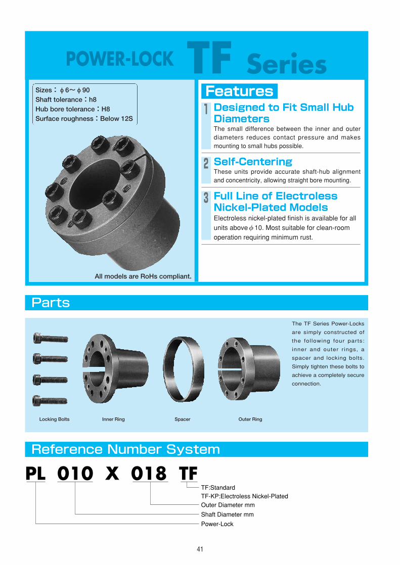
41
POWER-LOCK TF SeriesFeaturesSizes:φ6~φ90
Shaft tolerance:h8Hub bore tolerance:H8Surface roughness:Below 12S
1 Designed to Fit Small HubDiametersThe small difference between the inner and outerdiameters reduces contact pressure and makesmounting to small hubs possible.
2 Self-CenteringThese units provide accurate shaft-hub alignmentand concentricity, allowing straight bore mounting.
3 Full Line of ElectrolessNickel-Plated ModelsElectroless nickel-plated finish is available for allunits aboveφ10. Most suitable for clean-roomoperation requiring minimum rust.
Parts
Reference Number System
The TF Series Power-Locks
are simply constructed of
the fol lowing four parts:
inner and outer rings, a
spacer and locking bolts.
Simply tighten these bolts to
achieve a completely secure
connection.
PL 010 X 018 TF
Shaft Diameter mm
Power-Lock
Outer Diameter mm
TF:StandardTF-KP:Electroless Nickel-Plated�
�
Locking Bolts Inner Ring Spacer Outer Ring
All models are RoHs compliant.
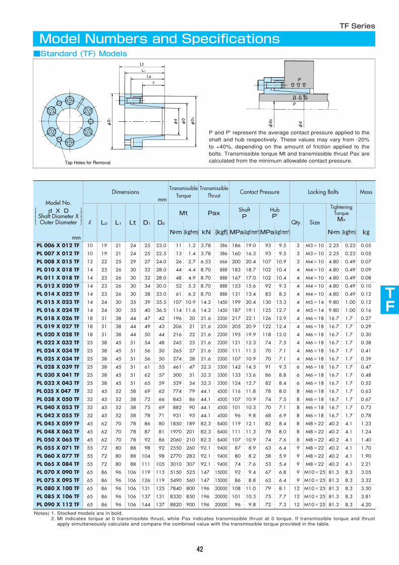
TF
424242
Dimensionsmm
TransmissibleTorque
TransmissibleThrust
Contact Pressure Locking Bolts Mass
R L0 L1 Lt D1 D2
Mt PaxShaftP
HubP′
Qty. Size
TighteningTorqueMA
N・m {kgf・m} kN {kgf} MPa{kgf/mm2}MPa{kgf/mm2} N・m {kgf・m} kg
PL 006 X 012 TFPL 007 X 012 TF
10 19 21 24 25 23.0 11 1.2 3.78 386 186 19.0 93 9.5 3 M3×10 2.25 0.23 0.05
10 19 21 24 25 22.5 13 1.4 3.78 386 160 16.3 93 9.5 3 M3×10 2.25 0.23 0.05
PL 008 X 015 TF 12 22 25 29 27 24.0 26 2.7 6.53 666 200 20.4 107 10.9 3 M4×10 4.80 0.49 0.07
PL 010 X 018 TF 14 23 26 30 32 28.0 44 4.4 8.70 888 183 18.7 102 10.4 4 M4×10 4.80 0.49 0.09
PL 011 X 018 TF 14 23 26 30 32 28.0 48 4.9 8.70 888 167 17.0 102 10.4 4 M4×10 4.80 0.49 0.08
PL 012 X 020 TF 14 23 26 30 34 30.0 52 5.3 8.70 888 153 15.6 92 9.3 4 M4×10 4.80 0.49 0.10
PL 014 X 022 TF 14 23 26 30 38 33.0 61 6.2 8.70 888 131 13.4 83 8.5 4 M4×10 4.80 0.49 0.12
PL 015 X 023 TF 14 24 30 35 39 35.5 107 10.9 14.2 1450 199 20.4 130 13.3 4 M5×14 9.80 1.00 0.12
PL 016 X 024 TF 14 24 30 35 40 36.5 114 11.6 14.2 1450 187 19.1 125 12.7 4 M5×14 9.80 1.00 0.16
PL 018 X 026 TF 18 31 38 44 47 42 196 20 21.6 2200 217 22.1 126 12.9 4 M6×18 16.7 1.7 0.27
PL 019 X 027 TF 18 31 38 44 49 43 206 21 21.6 2200 205 20.9 122 12.4 4 M6×18 16.7 1.7 0.29
PL 020 X 028 TF 18 31 38 44 50 44 216 22 21.6 2200 195 19.9 118 12.0 4 M6×18 16.7 1.7 0.30
PL 022 X 032 TF 25 38 45 51 54 48 245 25 21.6 2200 121 12.3 74 7.5 4 M6×18 16.7 1.7 0.38
PL 024 X 034 TF 25 38 45 51 56 50 265 27 21.6 2200 111 11.3 70 7.1 4 M6×18 16.7 1.7 0.41
PL 025 X 034 TF 25 38 45 51 56 50 274 28 21.6 2200 107 10.9 70 7.1 4 M6×18 16.7 1.7 0.39
PL 028 X 039 TF 25 38 45 51 61 55 461 47 32.3 3300 142 14.5 91 9.3 6 M6×18 16.7 1.7 0.47
PL 030 X 041 TF 25 38 45 51 62 57 500 51 32.3 3300 133 13.6 86 8.8 6 M6×18 16.7 1.7 0.48
PL 032 X 043 TF 25 38 45 51 65 59 529 54 32.3 3300 124 12.7 82 8.4 6 M6×18 16.7 1.7 0.52
PL 035 X 047 TF 32 45 52 58 69 62 774 79 44.1 4500 116 11.8 78 8.0 8 M6×18 16.7 1.7 0.63
PL 038 X 050 TF 32 45 52 58 72 66 843 86 44.1 4500 107 10.9 74 7.5 8 M6×18 16.7 1.7 0.67
PL 040 X 053 TF 32 45 52 58 75 69 882 90 44.1 4500 101 10.3 70 7.1 8 M6×18 16.7 1.7 0.73
PL 042 X 055 TF 32 45 52 58 78 71 931 95 44.1 4500 96 9.8 68 6.9 8 M6×18 16.7 1.7 0.78
PL 045 X 059 TF 45 62 70 78 86 80 1850 189 82.3 8400 119 12.1 82 8.4 8 M8×22 40.2 4.1 1.23
PL 048 X 062 TF 45 62 70 78 87 81 1970 201 82.3 8400 111 11.3 78 8.0 8 M8×22 40.2 4.1 1.24
PL 050 X 065 TF 45 62 70 78 92 86 2060 210 82.3 8400 107 10.9 74 7.6 8 M8×22 40.2 4.1 1.40
PL 055 X 071 TF 55 72 80 88 98 92 2550 260 92.1 9400 87 8.9 63 6.4 9 M8×22 40.2 4.1 1.70
PL 060 X 077 TF 55 72 80 88 104 98 2770 283 92.1 9400 80 8.2 58 5.9 9 M8×22 40.2 4.1 1.90
PL 065 X 084 TF 55 72 80 88 111 105 3010 307 92.1 9400 74 7.6 53 5.4 9 M8×22 40.2 4.1 2.21
PL 070 X 090 TF 65 86 96 106 119 113 5150 525 147 15000 92 9.4 67 6.8 9 M10×25 81.3 8.3 3.05
PL 075 X 095 TF 65 86 96 106 126 119 5490 560 147 15000 86 8.8 63 6.4 9 M10×25 81.3 8.3 3.32
PL 080 X 100 TF 65 86 96 106 131 125 7840 800 196 20000 108 11.0 79 8.1 12 M10×25 81.3 8.3 3.50
PL 085 X 106 TF 65 86 96 106 137 131 8330 850 196 20000 101 10.3 75 7.7 12 M10×25 81.3 8.3 3.81
PL 090 X 112 TF 65 86 96 106 144 137 8820 900 196 20000 96 9.8 72 7.3 12 M10×25 81.3 8.3 4.20
Notes) 1. Stocked models are in bold.2. Mt indicates torque at 0 transmissible thrust, while Pax indicates transmissible thrust at 0 torque. If transmissible torque and thrust
apply simultaneously calculate and compare the combined value with the transmissible torque provided in the table.
TF Series
Model Numbers and Specifications
Lt
Tap Holes for Removal
P and P' represent the average contact pressure applied to theshaft and hub respectively. These values may vary from -20%to +40%, depending on the amount of friction applied to thebolts. Transmissible torque Mt and transmissible thrust Pax arecalculated from the minimum allowable contact pressure.
mm
■Standard (TF) Models
Model No.d X D
Shaft Diameter XOuter Diameter
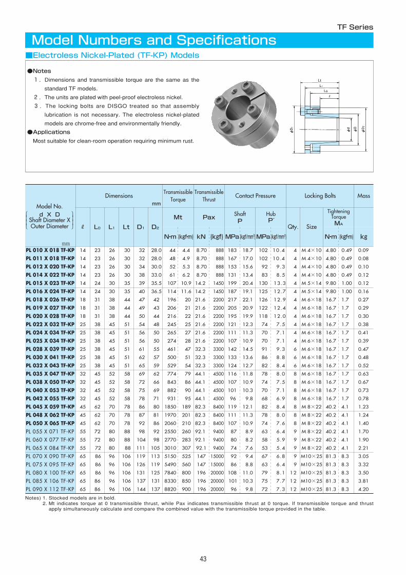
43
DimensionsTransmissible
TorqueTransmissible
ThrustContact Pressure Locking Bolts Mass
R
Mt PaxShaftP
HubP′
Qty.
TighteningTorqueMA
PL 010 X 018 TF-KP 14 44 8.70 183 102 4 4.80 0.09
PL 011 X 018 TF-KP 14 48 8.70 167 102 4 4.80 0.08
PL 012 X 020 TF-KP 14 52 8.70 153 92 4 4.80 0.10
PL 014 X 022 TF-KP 14 61 8.70 131 83 4 4.80 0.12
PL 015 X 023 TF-KP 14 107 14.2 199 130 4 9.80 0.12
PL 016 X 024 TF-KP 14 114 14.2 187 125 4 9.80 0.16
PL 018 X 026 TF-KP 18 196 21.6 217 126 4 16.7 0.27
PL 019 X 027 TF-KP 18 206 21.6 205 122 4 16.7 0.29
PL 020 X 028 TF-KP 18 216 21.6 195 118 4 16.7 0.30
PL 022 X 032 TF-KP 25 245 21.6 121 74 4 16.7 0.38
PL 024 X 034 TF-KP 25 265 21.6 111 70 4 16.7 0.41
PL 025 X 034 TF-KP 25 274 21.6 107 70 4 16.7 0.39
PL 028 X 039 TF-KP 25 461 32.3 142 91 6 16.7 0.47
PL 030 X 041 TF-KP 25 500 32.3 133 86 6 16.7 0.48
PL 032 X 043 TF-KP 25 529 32.3 124 82 6 16.7 0.52
PL 035 X 047 TF-KP 32 774 44.1 116 78 8 16.7 0.63
PL 038 X 050 TF-KP 32 843 44.1 107 74 8 16.7 0.67
PL 040 X 053 TF-KP 32 882 44.1 101 70 8 16.7 0.73
PL 042 X 055 TF-KP 32 931 44.1 96 68 8 16.7 0.78
PL 045 X 059 TF-KP 45 1850 82.3 119 82 8 40.2 1.23
PL 048 X 062 TF-KP 45 1970 82.3 111 78 8 40.2 1.24
PL 050 X 065 TF-KP 45 2060 82.3 107 74 8 40.2 1.40
PL 055 X 071 TF-KP 55 2550 92.1 87 63 9 40.2 1.70
PL 060 X 077 TF-KP 55 2770 92.1 80 58 9 40.2 1.90
PL 085 X 106 TF-KP 65 8330 196 101 75 12 81.3 3.81
PL 090 X 112 TF-KP 65 8820 196 96 72 12 81.3 4.20
L0 L1 Lt D1 D2
23 26 30 32 28.0 4.4
23 26 30 32 28.0 4.9
23 26 30 34 30.0 5.3
23 26 30 38 33.0 6.2
24 30 35 39 35.5 10.9
24 30 35 40 36.5 11.6
31 38 44 47 42 20
31 38 44 49 43 21
31 38 44 50 44 22
38 45 51 54 48 25
38 45 51 56 50 27
38 45 51 56 50 28
38 45 51 61 55 47
38 45 51 62 57 51
38 45 51 65 59 54
45 52 58 69 62 79
45 52 58 72 66 86
45 52 58 75 69 90
45 52 58 78 71 95
62 70 78 86 80 189
62 70 78 87 81 201
62 70 78 92 86 210
72 80 88 98 92 260
72 80 88 104 98 283
86 96 106 137 131 850
86 96 106 144 137 900
888 18.7 10.4
888 17.0 10.4
888 15.6 9.3
888 13.4 8.5
1450 20.4 13.3
1450 19.1 12.7
2200 22.1 12.9
2200 20.9 12.4
2200 19.9 12.0
2200 12.3 7.5
2200 11.3 7.1
2200 10.9 7.1
3300 14.5 9.3
3300 13.6 8.8
3300 12.7 8.4
4500 11.8 8.0
4500 10.9 7.5
4500 10.3 7.1
4500 9.8 6.9
8400 12.1 8.4
8400 11.3 8.0
8400 10.9 7.6
9400 8.9 6.4
9400 8.2 5.9
20000 10.3 7.7
20000 9.8 7.3
Size
M 4×10 0.49
M 4×10 0.49
M 4×10 0.49
M 4×10 0.49
M 5×14 1.00
M 5×14 1.00
M 6×18 1.7
M 6×18 1.7
M 6×18 1.7
M 6×18 1.7
M 6×18 1.7
M 6×18 1.7
M 6×18 1.7
M 6×18 1.7
M 6×18 1.7
M 6×18 1.7
M 6×18 1.7
M 6×18 1.7
M 6×18 1.7
M 8×22 4.1
M 8×22 4.1
M 8×22 4.1
M 8×22 4.1
M 8×22 4.1
M10×25 8.3
M10×25 8.3
N・m {kgf・m} kN {kgf} MPa {kgf/mm2}MPa {kgf/mm2} N・m {kgf・m}
■Electroless Nickel-Plated (TF-KP) Models
TF Series
Model Numbers and Specifications
●Notes
1.Dimensions and transmissible torque are the same as the
standard TF models.
2.The units are plated with peel-proof electroless nickel.
3.The locking bolts are DISGO treated so that assembly
lubrication is not necessary. The electroless nickel-plated
models are chrome-free and environmentally friendly.
●Applications
Most suitable for clean-room operation requiring minimum rust.
Notes) 1. Stocked models are in bold.2. Mt indicates torque at 0 transmissible thrust, while Pax indicates transmissible thrust at 0 torque. If transmissible torque and thrust
apply simultaneously calculate and compare the combined value with the transmissible torque provided in the table.
mm
mm
PL 065 X 084 TF-KP 55 72 80 88 111 105 3010 307 92.1 9400 74 7.6 53 5.4 9 M 8×22 40.2 4.1 2.21
PL 070 X 090 TF-KP 65 86 96 106 119 113 5150 525 147 15000 92 9.4 67 6.8 9 M10×25 81.3 8.3 3.05
PL 075 X 095 TF-KP 65 86 96 106 126 119 5490 560 147 15000 86 8.8 63 6.4 9 M10×25 81.3 8.3 3.32
PL 080 X 100 TF-KP 65 86 96 106 131 125 7840 800 196 20000 108 11.0 79 8.1 12 M10×25 81.3 8.3 3.50
kg
Lt
Model No.d X D
Shaft Diameter XOuter Diameter
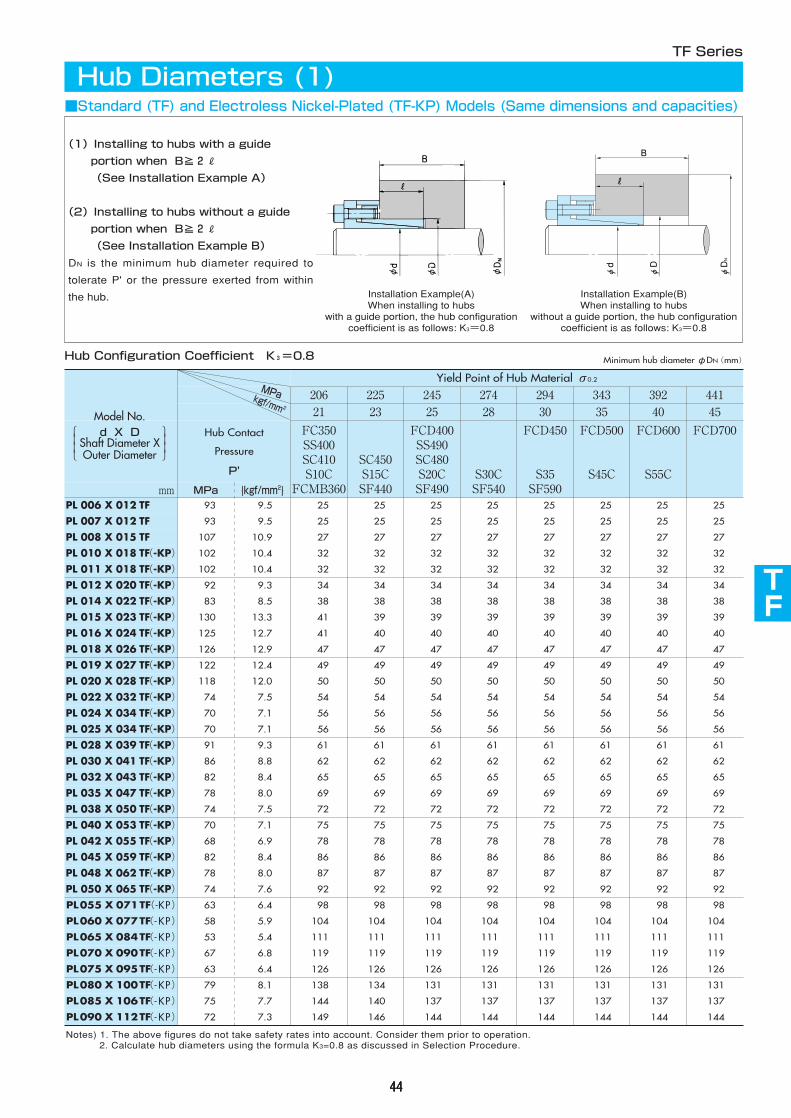
206 225 245 274 294 34321 23 25 28 30 35
Hub Contact
Pressure
P'
FC350SS400SC410S10C
FCMB360
SC450S15CSF440
FCD400SS490SC480S20CSF490
S30CSF540
FCD450
S35SF590
FCD500
S45Cmm MPa {kgf/mm2}
PL 006 X 012 TF(-KP) 93 9.5 25 25 25 25 25 25
PL 007 X 012 TF(-KP) 93 9.5 25 25 25 25 25 25
PL 008 X 015 TF(-KP) 107 10.9 27 27 27 27 27 27
PL 010 X 018 TF(-KP) 102 10.4 32 32 32 32 32 32
PL 011 X 018 TF(-KP) 102 10.4 32 32 32 32 32 32
PL 012 X 020 TF(-KP) 92 9.3 34 34 34 34 34 34
PL 014 X 022 TF(-KP) 83 8.5 38 38 38 38 38 38
PL 015 X 023 TF(-KP) 130 13.3 41 39 39 39 39 39
PL 016 X 024 TF(-KP) 125 12.7 41 40 40 40 40 40
PL 018 X 026 TF(-KP) 126 12.9 47 47 47 47 47 47
PL 019 X 027 TF(-KP) 122 12.4 49 49 49 49 49 49
PL 020 X 028 TF(-KP) 118 12.0 50 50 50 50 50 50
PL 022 X 032 TF(-KP) 74 7.5 54 54 54 54 54 54
PL 024 X 034 TF(-KP) 70 7.1 56 56 56 56 56 56
PL 025 X 034 TF(-KP) 70 7.1 56 56 56 56 56 56
PL 028 X 039 TF(-KP) 91 9.3 61 61 61 61 61 61
PL 030 X 041 TF(-KP) 86 8.8 62 62 62 62 62 62
PL 032 X 043 TF(-KP) 82 8.4 65 65 65 65 65 65
PL 035 X 047 TF(-KP) 78 8.0 69 69 69 69 69 69
PL 038 X 050 TF(-KP) 74 7.5 72 72 72 72 72 72
PL 040 X 053 TF(-KP) 70 7.1 75 75 75 75 75 75
PL 042 X 055 TF(-KP) 68 6.9 78 78 78 78 78 78
PL 045 X 059 TF(-KP) 82 8.4 86 86 86 86 86 86
PL 048 X 062 TF(-KP) 78 8.0 87 87 87 87 87 87
PL 050 X 065 TF(-KP) 74 7.6 92 92 92 92 92 92
PL055 X 071TF(-KP) 63 6.4 98 98 98 98 98 98
PL060 X 077TF(-KP) 58 5.9 104 104 104 104 104 104
PL065 X 084TF(-KP) 53 5.4 111 111 111 111 111 111
PL070 X 090TF(-KP) 67 6.8 119 119 119 119 119 119
PL075 X 095TF(-KP) 63 6.4 126 126 126 126 126 126
392 44140 45
FCD600
S55C
FCD700
25 25
25 25
27 27
32 32
32 32
34 34
38 38
39 39
40 40
47 47
49 49
50 50
54 54
56 56
56 56
61 61
62 62
65 65
69 69
72 72
75 75
78 78
86 86
87 87
92 92
98 98
104 104
111 111
119 119
126 126
PL080 X 100TF(-KP) 79 8.1 138 134 131 131 131 131 131 131
PL085 X 106TF(-KP) 75 7.7 144 140 137 137 137 137 137 137
PL090 X 112TF(-KP) 72 7.3 149 146 144 144 144 144 144 144
Yield Point of Hub Material σ0.2
MPakgf/mm 2
TF
44444444
Notes) 1. The above figures do not take safety rates into account. Consider them prior to operation.2. Calculate hub diameters using the formula K3=0.8 as discussed in Selection Procedure.
Hub Configuration Coefficient K3=0.8
TF Series
Hub Diameters (1)
(1)Installing to hubs with a guide
portion when B≧2R
(See Installation Example A)
(2)Installing to hubs without a guide
portion when B≧2R
(See Installation Example B)
DN is the minimum hub diameter required to
tolerate P' or the pressure exerted from within
the hub.
B
φd
φD
φDN
Minimum hub diameterφDN(mm)
■Standard (TF) and Electroless Nickel-Plated (TF-KP) Models (Same dimensions and capacities)
Model No.d X D
Shaft Diameter XOuter Diameter
Installation Example(A)When installing to hubs
with a guide portion, the hub configurationcoefficient is as follows: K3=0.8
Installation Example(B)When installing to hubs
without a guide portion, the hub configurationcoefficient is as follows: K3=0.8
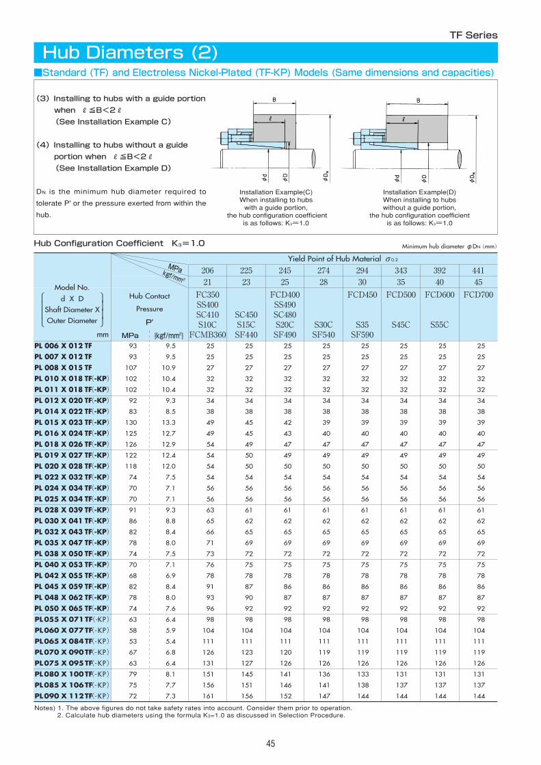
206 225 245 274 294 34321 23 25 28 30 35
Hub Contact
Pressure
P'
FC350SS400SC410S10C
FCMB360
SC450S15CSF440
FCD400SS490SC480S20CSF490
S30CSF540
FCD450
S35SF590
FCD500
S45Cmm MPa {kgf/mm2}
PL 006 X 012 TF(-KP) 93 9.5 25 25 25 25 25 25
PL 007 X 012 TF(-KP) 93 9.5 25 25 25 25 25 25
PL 008 X 015 TF(-KP) 107 10.9 27 27 27 27 27 27
PL 010 X 018 TF(-KP) 102 10.4 32 32 32 32 32 32
PL 011 X 018 TF(-KP) 102 10.4 32 32 32 32 32 32
PL 012 X 020 TF(-KP) 92 9.3 34 34 34 34 34 34
PL 014 X 022 TF(-KP) 83 8.5 38 38 38 38 38 38
PL 015 X 023 TF(-KP) 130 13.3 49 45 42 39 39 39
PL 016 X 024 TF(-KP) 125 12.7 49 45 43 40 40 40
PL 018 X 026 TF(-KP) 126 12.9 54 49 47 47 47 47
PL 019 X 027 TF(-KP) 122 12.4 54 50 49 49 49 49
PL 020 X 028 TF(-KP) 118 12.0 54 50 50 50 50 50
PL 022 X 032 TF(-KP) 74 7.5 54 54 54 54 54 54
PL 024 X 034 TF(-KP) 70 7.1 56 56 56 56 56 56
PL 025 X 034 TF(-KP) 70 7.1 56 56 56 56 56 56
PL 028 X 039 TF(-KP) 91 9.3 63 61 61 61 61 61
PL 030 X 041 TF(-KP) 86 8.8 65 62 62 62 62 62
PL 032 X 043 TF(-KP) 82 8.4 66 65 65 65 65 65
PL 035 X 047 TF(-KP) 78 8.0 71 69 69 69 69 69
PL 038 X 050 TF(-KP) 74 7.5 73 72 72 72 72 72
PL 040 X 053 TF(-KP) 70 7.1 76 75 75 75 75 75
PL 042 X 055 TF(-KP) 68 6.9 78 78 78 78 78 78
PL 045 X 059 TF(-KP) 82 8.4 91 87 86 86 86 86
PL 048 X 062 TF(-KP) 78 8.0 93 90 87 87 87 87
PL 050 X 065 TF(-KP) 74 7.6 96 92 92 92 92 92
PL055 X 071TF(-KP) 63 6.4 98 98 98 98 98 98
PL060 X 077TF(-KP) 58 5.9 104 104 104 104 104 104
PL065 X 084TF(-KP) 53 5.4 111 111 111 111 111 111
PL070 X 090TF(-KP) 67 6.8 126 123 120 119 119 119
PL075 X 095TF(-KP) 63 6.4 131 127 126 126 126 126
392 44140 45
FCD600
S55C
FCD700
25 25
25 25
27 27
32 32
32 32
34 34
38 38
39 39
40 40
47 47
49 49
50 50
54 54
56 56
56 56
61 61
62 62
65 65
69 69
72 72
75 75
78 78
86 86
87 87
92 92
98 98
104 104
111 111
119 119
126 126
PL080 X 100TF(-KP) 79 8.1 151 145 141 136 133 131 131 131
PL085 X 106TF(-KP) 75 7.7 156 151 146 141 138 137 137 137
PL090 X 112TF(-KP) 72 7.3 161 156 152 147 144 144 144 144
Yield Point of Hub Material σ0.2
45
Notes) 1. The above figures do not take safety rates into account. Consider them prior to operation.2. Calculate hub diameters using the formula K3=1.0 as discussed in Selection Procedure.
TF Series
Hub Diameters (2)
Hub Configuration Coefficient K3=1.0
(3)Installing to hubs with a guide portion
when R≦B<2R
(See Installation Example C)
(4)Installing to hubs without a guide
portion when R≦B<2R
(See Installation Example D)
DN is the minimum hub diameter required to
tolerate P' or the pressure exerted from within the
hub.
Minimum hub diameterφDN(mm)
■Standard (TF) and Electroless Nickel-Plated (TF-KP) Models (Same dimensions and capacities)
MPakgf/mm 2
Installation Example(C)When installing to hubswith a guide portion,
the hub configuration coefficientis as follows: K3=1.0
Installation Example(D)When installing to hubswithout a guide portion,
the hub configuration coefficientis as follows: K3=1.0
Model No.
d X DShaft Diameter XOuter Diameter
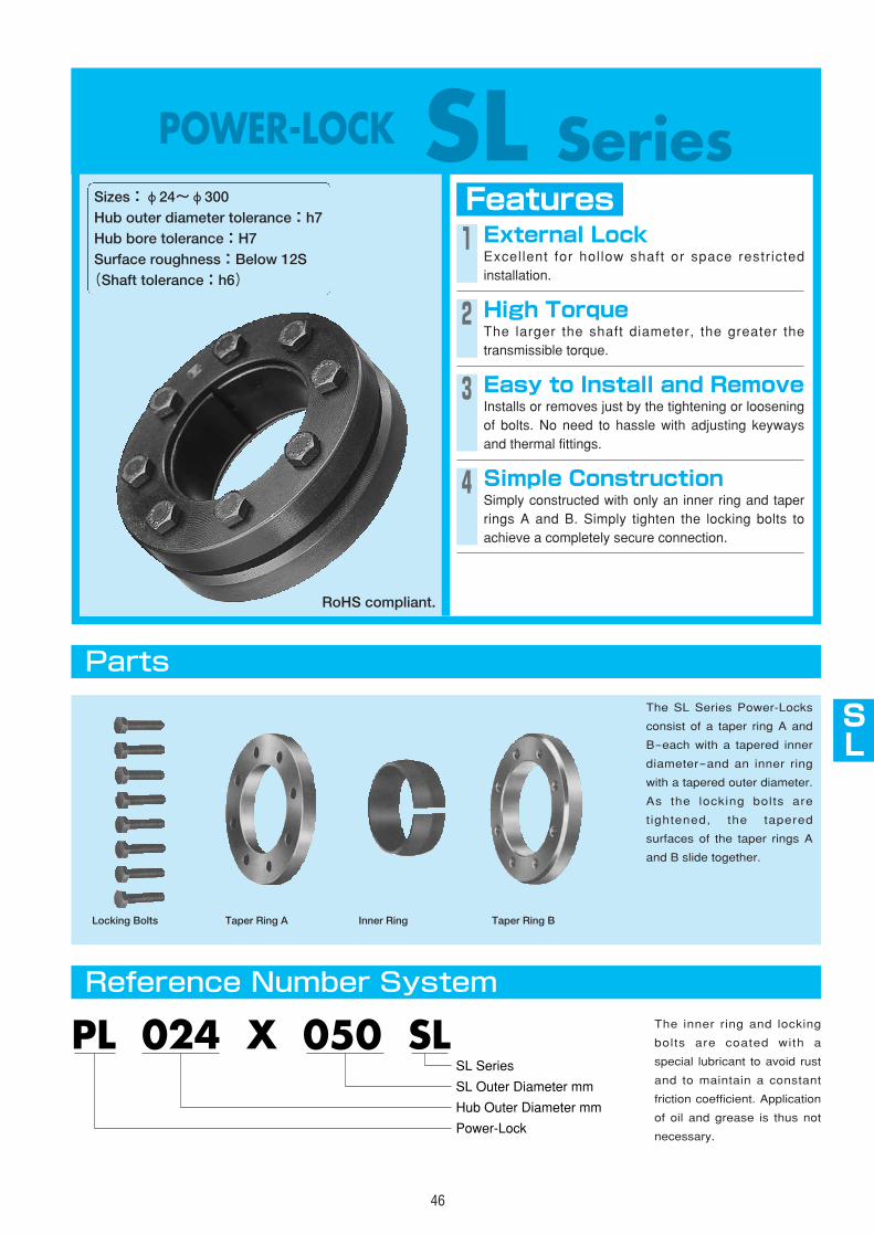
AS
AS
AS
AS
AS
TF
SL
AS
AS
AS
46
POWER-LOCK SL SeriesFeaturesSizes:φ24~φ300
Hub outer diameter tolerance:h7Hub bore tolerance:H7Surface roughness:Below 12S(Shaft tolerance:h6)
1 External LockExcellent for hollow shaft or space restrictedinstallation.
3 Easy to Install and RemoveInstalls or removes just by the tightening or looseningof bolts. No need to hassle with adjusting keywaysand thermal fittings.
4 Simple ConstructionSimply constructed with only an inner ring and taperrings A and B. Simply tighten the locking bolts toachieve a completely secure connection.
Parts
Reference Number System
The SL Series Power-Locks
consist of a taper ring A and
B-each with a tapered inner
diameter-and an inner ring
with a tapered outer diameter.
As the locking bolts are
tightened, the tapered
surfaces of the taper rings A
and B slide together.
PL 024 X 050 SL
Hub Outer Diameter mm
Power-Lock
SL Outer Diameter mm
SL Series
Locking Bolts Taper Ring A Inner Ring Taper Ring B
The inner ring and locking
bolts are coated with a
special lubricant to avoid rust
and to maintain a constant
friction coefficient. Application
of oil and grease is thus not
necessary.
2 High TorqueThe larger the shaft diameter, the greater thetransmissible torque.
RoHS compliant.
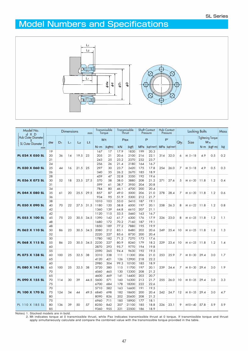
47
mm
Dimensions mm
dw L1 Lt Size{kgf・m} {kgf・m}
1936 14 19.5 23
167 17 17.9 1830 199 20.3314 32.0 6 M 5×18 4.9 0.5 0.2 20 205 21 20.6 2100 216 22.1
21
PL 030 X 060 SL24
44 16 21.5 25256 26 21.4 2180 164 16.7
254 26.0 7 M 5×18 4.9 0.5 0.3 2526
PL 036 X 072 SL28
52 18 23.5 27.5459 47 32.8 3350 192 19.6
271 27.6 5 M 6×20 11.8 1.2 0.4 3031
PL 044 X 080 SL34
61 20 25.5 29.5784 80 46.1 4700 200 20.4
278 28.4 7 M 6×20 11.8 1.2 0.6 3536
PL 050 X 090 SL38
70 22 27.5 31.51010 103 53.0 5410 187 19.1
258 26.3 8 M 6×22 11.8 1.2 0.8 4042
PL 055 X 100 SL42
75 23 30.5 34.51120 115 53.5 5460 163 16.7
226 23.0 8 M 6×25 11.8 1.2 1.1 4548
PL 062 X 110 SL48
86 23 30.5 34.51850 189 77.2 7880 195 19.9
249 25.4 10 M 6×25 11.8 1.2 1.3 5052 2220 227 85.6 8730 200 20.4
PL 068 X 115 SL50
86
243 23.7
297 17.8340 18.9
570 21.2599 20.8
857 21.0934 21.7
1180 20.11360 21.1
1390 17.91680 19.1
2080 20.6
34.51780 17.6
229 M 6×25 11.8
TransmissibleTorque
TransmissibleThrust
Shaft ContactPressure
Hub ContactPressure Locking Bolts Mass
D1 L2Mt Pax P P'
Qty.Tightening Torque
MA
kgN・m kN {kgf} MPa {kgf/mm2} MPa {kgf/mm2} N・m
PL 024 X 050 SL25 23.2 2370 232
30 23.7 2420 175 35 26.2 2670 185
58 38.0 3880 208 61 38.7 3950 204
87 49.0 5000 206 95 51.9 5300 212
120 58.8 6000 197 139 64.8 6610 207
142 61.7 6300 176 172 70.2 7160 187
212 83.1 8480 202
23 30.5182 71.2 7270 173
23.4 10 1.2 1.4 55 2230 227 80.9 8260 179 18.260 2870 293 95.7 9770 194 19.8
PL 075 X 138 SL55
100 25 32.5 382590 265 94.4 9630 192 19.5
253 25.9 7 M 8×30 29.4 3.0 1.7 60 3310 338 111 11300 206 21.065 4120 421 126 12900 218 22.2
PL 080 X 145 SL60
100 25 32.5 382980 304 99.3 10100 185 18.9
239 24.4 7 M 8×30 29.4 3.0 1.9 65 3720 380 115 11700 197 20.170 4560 465 130 13300 208 21.2
PL 090 X 155 SL65
114 30 39 44.54600 469 141 14400 203 20.7
255 26.0 10 M 8×35 29.4 3.0 3.3 70 5600 571 160 16300 213 21.775 6700 684 178 18200 222 22.6
PL 100 X 170 SL70
124 34 44 49.55710 582 163 16600 191 19.5
242 24.7 12 M 8×35 29.4 3.0 4.7 75 6840 698 182 18600 200 20.480 8090 826 202 20600 208 21.2
PL 110 X 185 SL75
136 39 50 576960 711 185 18900 177 18.1
226 23.1 9 M10×40 57.8 5.9 5.9 80 8250 842 207 21100 185 18.885 9360 955 221 22500 186 18.9
Notes) 1. Stocked models are in bold.2. Mt indicates torque at 0 transmissible thrust, while Pax indicates transmissible thrust at 0 torque. If transmissible torque and thrust
apply simultaneously calculate and compare the combined value with the transmissible torque provided in the table.
Model Numbers and SpecificationsSL Series
Model No.d X D
Hub Outer DiameterX
SL Outer Diameter
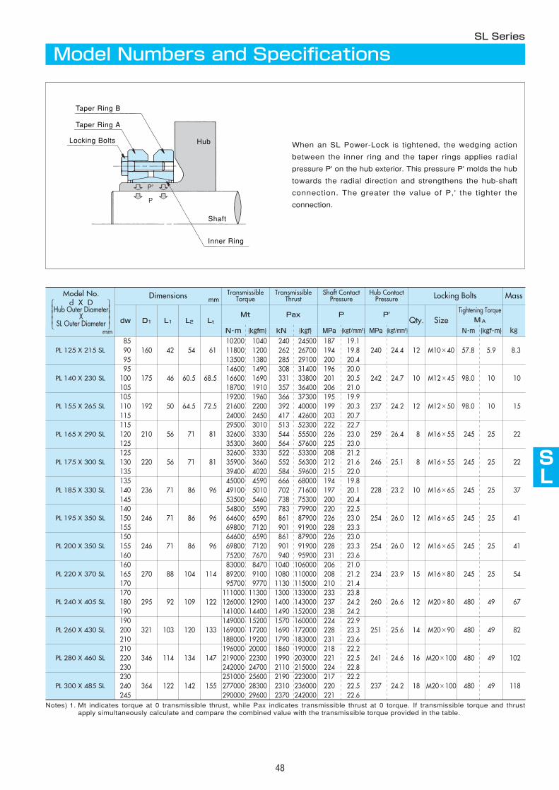
AS
AS
AS
AS
AS
AS
SL
AS
AS
AS
48
Dimensions mm
dw L1 Lt Size{kgf・m} {kgf・m}
85160 42 54 61
10200 1040 240 24500 187 19.1240 24.4 12 M10×40 57.8 5.9 8.3 90 11800 1200 262 26700 194 19.8
95
PL 140 X 230 SL95
175 46 60.5 68.514600 1490 308 31400 196 20.0
242 24.7 10 M12×45 98.0 10 10100 105
PL 155 X 265 SL105
192 50 64.5 72.519200 1960 366 37300 195 19.9
237 24.2 12 M12×50 98.0 10 15110 115
PL 165 X 290 SL115
210 56 71 8129500 3010 513 52300 222 22.7
259 26.4 8 M16×55 245 25 22120 125
PL 175 X 300 SL125
220 56 71 8132600 3330 522 53300 208 21.2
246 25.1 8 M16×55 245 25 22130 135
PL 185 X 330 SL135
236 71 86 9645000 4590 666 68000 194 19.8
228 23.2 10 M16×65 245 25 37140 145
PL 195 X 350 SL140
246 71 86 9654800 5590 783 79900 220 22.5
254 26.0 12 M16×65 245 25 41150 155 69800 7120 901 91900 228 23.3
PL 200 X 350 SL150
246
13500 20.4
16600 20.518700 21.0
21600 20.324000 20.7
32600 23.035300 23.0
35900 21.639400 22.0
49100 20.153500 20.4
64600 23.0
9664600 23.0
254 M16×65 245
TransmissibleTorque
TransmissibleThrust
Shaft ContactPressure
Hub ContactPressure Locking Bolts Mass
D1 L2Mt Pax P P'
Qty.Tightening Torque
MA
kgN・m kN {kgf} MPa {kgf/mm2} MPa {kgf/mm2} N・m
PL 125 X 215 SL1380 285 29100 200
1690 331 33800 201 1910 357 36400 206
2200 392 40000 199 2450 417 42600 203
3330 544 55500 226 3600 564 57600 225
3660 552 56300 212 4020 584 59600 215
5010 702 71600 197 5460 738 75300 200
6590 861 87900 226
71 866590 861 87900 226
26.0 12 25 41155 69800 7120 901 91900 228 23.3160 75200 7670 940 95900 231 23.6
PL 220 X 370 SL160
270 88 104 114 83000 8470 1040 106000 206 21.0
234 23.9 15 M16×80 245 25 54165 89200 9100 1080 110000 208 21.2170 95700 9770 1130 115000 210 21.4
PL 240 X 405 SL170
295 92 109 122 111000 11300 1300 133000 233 23.8
260 26.6 12 M20×80 480 49 67180 126000 12900 1400 143000 237 24.2190 141000 14400 1490 152000 238 24.2
PL 260 X 430 SL190
321 103 120 133 149000 15200 1570 160000 224 22.9
251 25.6 14 M20×90 480 49 82200 169000 17200 1690 172000 228 23.3210 188000 19200 1790 183000 231 23.6
PL 280 X 460 SL210
346 114 134 147 196000 20000 1860 190000 218 22.2
241 24.6 16 M20×100 480 49 102 220 219000 22300 1990 203000 221 22.5230 242000 24700 2110 215000 224 22.8
PL 300 X 485 SL230
364 122 142 155 251000 25600 2190 223000 217 22.2
237 24.2 18 M20×100 480 49 118 240 277000 28300 2310 236000 220 22.5245 290000 29600 2370 242000 221 22.6
Notes) 1. Mt indicates torque at 0 transmissible thrust, while Pax indicates transmissible thrust at 0 torque. If transmissible torque and thrustapply simultaneously calculate and compare the combined value with the transmissible torque provided in the table.
Model Numbers and SpecificationsSL Series
Taper Ring A
Taper Ring B
Locking Bolts
Inner Ring
Shaft
Hub When an SL Power-Lock is tightened, the wedging action
between the inner ring and the taper rings applies radial
pressure P' on the hub exterior. This pressure P' molds the hub
towards the radial direction and strengthens the hub-shaft
connection. The greater the value of P,' the tighter the
connection.
mm
Model No.d X D
Hub Outer DiameterX
SL Outer Diameter
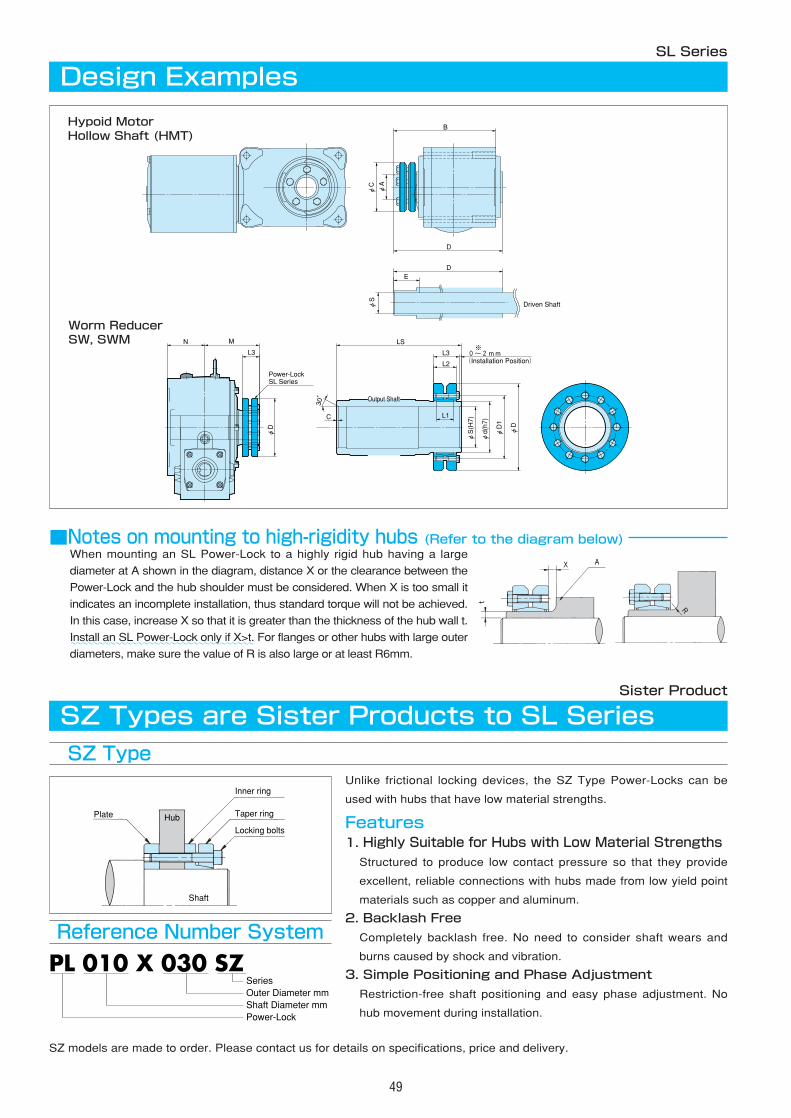
49
Design ExamplesSL Series
Driven ShaftφS
B
D
DE
φA
φC
SL SeriesPower-Lock
Output Shaft
※�
(Installation Position)�
N M
L3
φD
30°�
C
L3
L2
L1
φS(H7)
φd(h7)
φD1
φD
LS
0~2mm�
Hypoid MotorHollow Shaft (HMT)
Worm ReducerSW, SWM
When mounting an SL Power-Lock to a highly rigid hub having a large
diameter at A shown in the diagram, distance X or the clearance between the
Power-Lock and the hub shoulder must be considered. When X is too small it
indicates an incomplete installation, thus standard torque will not be achieved.
In this case, increase X so that it is greater than the thickness of the hub wall t.
Install an SL Power-Lock only if X>t. For flanges or other hubs with large outer
diameters, make sure the value of R is also large or at least R6mm.
■Notes on mounting to high-rigidity hubs (Refer to the diagram below)
~~~~~~~~~~~~~~~~~~~~~~~~~~~~~~~~~
Sister Product
Unlike frictional locking devices, the SZ Type Power-Locks can be
used with hubs that have low material strengths.
Features1. Highly Suitable for Hubs with Low Material Strengths
Structured to produce low contact pressure so that they provide
excellent, reliable connections with hubs made from low yield point
materials such as copper and aluminum.
2. Backlash Free
Completely backlash free. No need to consider shaft wears and
burns caused by shock and vibration.
3. Simple Positioning and Phase Adjustment
Restriction-free shaft positioning and easy phase adjustment. No
hub movement during installation.
SZ models are made to order. Please contact us for details on specifications, price and delivery.
SZ Type
SZ Types are Sister Products to SL Series
Reference Number System
Plate Hub
Shaft
Inner ring
Taper ring
Locking bolts
PL 010 X 030 SZ
Power-LockShaft Diameter mmOuter Diameter mmSeries
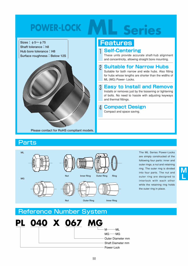
AS
AS
AS
AS
AS
AS
SL
ML
AS
AS
50
POWER-LOCK ML SeriesFeaturesSizes:φ5~φ75
Shaft tolerance:h8Hub bore tolerance:H8Surface roughness:Below 12S
1 Self-CenteringThese units provide accurate shaft-hub alignmentand concentricity, allowing straight bore mounting.
2 Suitable for Narrow HubsSuitable for both narrow and wide hubs. Also fittingfor hubs whose lengths are shorter than the widths ofML (MG) Power- Locks.
3 Easy to Install and RemoveInstalls or removes just by the loosening or tighteningof bolts. No need to hassle with adjusting keywaysand thermal fittings.
4 Compact DesignCompact and space saving.
Parts
Reference Number System
The ML Series Power-Locks
are simply constructed of the
following four parts: inner and
outer rings, a nut and retaining
ring. The outer ring is divided
into four parts. The nut and
outer ring are designed to
interlock with each other
while the retaining ring holds
the outer ring in place.
PL 040 X 067 MG
Shaft Diameter mm
Power-Lock
Outer Diameter mm
M………ML�
MG……MG
Nut
ML
MGInner Ring Outer Ring Ring
Nut Outer Ring Inner Ring
Please contact for RoHS compliant models.
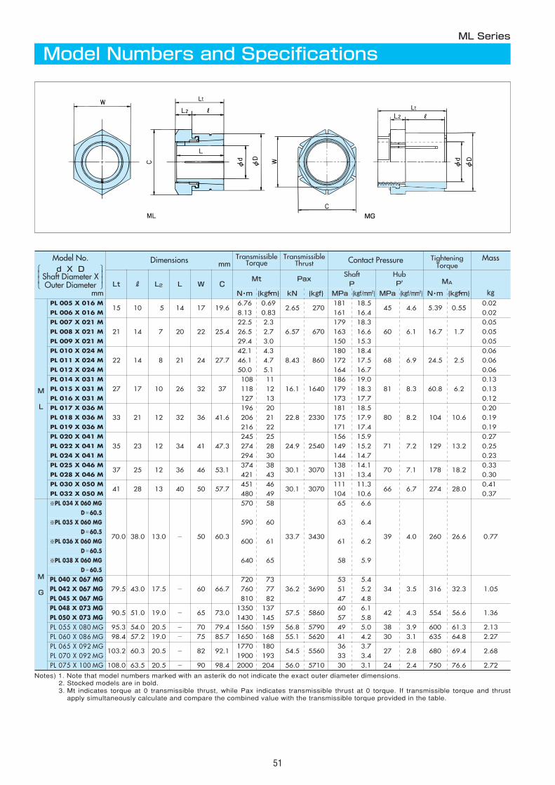
51
Notes) 1. Note that model numbers marked with an asterik do not indicate the exact outer diameter dimensions.2. Stocked models are in bold.3. Mt indicates torque at 0 transmissible thrust, while Pax indicates transmissible thrust at 0 torque. If transmissible torque and thrust
apply simultaneously calculate and compare the combined value with the transmissible torque provided in the table.
Dimensions mmTransmissible
TorqueTransmissible
Thrust Contact Pressure TighteningTorque
MA
Mass
kgLt R L2 L W C
Mt PaxShaftP
HubP'
N・m {kgf・m} kN {kgf} MPa {kgf/mm2} MPa {kgf/mm2} N・m {kgf・m}
M
L
PL 005 X 016 M15 10 5 14 17 19.6
6.76 0.692.65 270
181 18.545 4.6 5.39 0.55
0.02PL 006 X 016 M 8.13 0.83 161 16.4 0.02PL 007 X 021 M
21 14 7 20 22 25.422.5 2.3
6.57 670 179 18.3
60 6.1 16.7 1.7 0.05
PL 008 X 021 M 26.5 2.7 163 16.6 0.05PL 009 X 021 M 29.4 3.0 150 15.3 0.05PL 010 X 024 M
22 14 8 21 24 27.742.1 4.3
8.43 860 180 18.4
68 6.9 24.5 2.5 0.06
PL 011 X 024 M 46.1 4.7 172 17.5 0.06PL 012 X 024 M 50.0 5.1 164 16.7 0.06PL 014 X 031 M
27 17 10 26 32 37108 11
16.1 1640186 19.0
81 8.3 60.8 6.2 0.13
PL 015 X 031 M 118 12 179 18.3 0.13PL 016 X 031 M 127 13 173 17.7 0.12PL 017 X 036 M
33 21 12 32 36 41.6196 20
22.8 2330181 18.5
80 8.2 104 10.60.20
PL 018 X 036 M 206 21 175 17.9 0.19PL 019 X 036 M 216 22 171 17.4 0.19PL 020 X 041 M
35 23 12 34 41 47.3245 25
24.9 2540156 15.9
71 7.2 129 13.20.27
PL 022 X 041 M 274 28 149 15.2 0.25PL 024 X 041 M 294 30 144 14.7 0.23PL 025 X 046 M
37 25 12 36 46 53.1374 38
30.1 3070138 14.1
70 7.1 178 18.20.33
PL 028 X 046 M 421 43 131 13.4 0.30
PL 060 X 086 MG 1650 168 41 4.2
PL 030 X 050 M41 28 13 40 50 57.7
451 4630.1 3070
111 11.366 6.7 274 28.0
0.41PL 032 X 050 M 480 49 104 10.6 0.37
M
G
※PL 034 X 060 MG
70.0 38.0 13.0 - 50 60.3
570 58
33.7 3430
65 6.6
39 4.0 260 26.6 0.77
D=60.5
※PL 035 X 060 MG 590 60 63 6.4D=60.5
※PL 036 X 060 MG 600 61 61 6.2D=60.5
※PL 038 X 060 MG 640 65 58 5.9D=60.5
PL 040 X 067 MG79.5 43.0 17.5 - 60 66.7
720 7336.2 3690
53 5.4 34 3.5 316 32.3 1.05PL 042 X 067 MG 760 77 51 5.2
PL 045 X 067 MG 810 82 47 4.8 PL 048 X 073 MG
90.5 51.0 19.0 - 65 73.01350 137
57.5 586060 6.1
42 4.3 554 56.6 1.36PL 050 X 073 MG 1430 145 57 5.8 PL 055 X 080 MG 95.3 54.0 20.5 - 70 79.4 1560 159 56.8 5790 49 5.0 38 3.9 600 61.3 2.13
98.4 57.2 19.0 - 75 85.7 55.1 5620 30 3.1 635 64.8 2.27PL 065 X 092 MG
103.2 60.3 20.5 - 82 92.11770 180
54.5 556036 3.7
27 2.8 680 69.4 2.68PL 070 X 092 MG 1900 193 33 3.4 PL 075 X 100 MG 108.0 63.5 20.5 - 90 98.4 2000 204 56.0 5710 30 3.1 24 2.4 750 76.6 2.72
ML Series
Model Numbers and Specifications
MG
LtLt
mm
Model No.d X D
Shaft Diameter XOuter Diameter
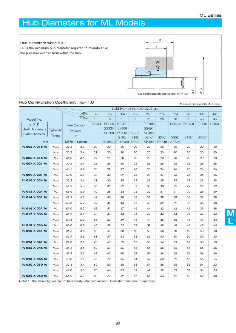
AS
AS
AS
AS
AS
AS
AS
ML
AS
AS
52
Yield Point of Hub Material σ0.2
TighteningTorque
Hub Contact
Pressure
P'
147 176 206 225 245 274 294 343 392 441
15 18 21 23 25 28 30 35 40 45
FC250 FC300 FC350 FCD400 FCD450 FCD500 FCD600 FCD700SS330 SS400 SS490SC360 SC410 SC450 SC480
S10C S15C S20C S30C S35C S45C S55CMPa {kgf/mm2} FCMB310FCMB360 SF440 SF490 SF540 SF590
PL 030 X 050 M MA50 33.3 3.4 62 60 58 58 57 56 56 55 54 53
〜 MA75 49.0 5.0 70 66 63 62 61 59 59 57 56 55
PL 032 X 050 M MA 66.0 6.7 80 73 69 67 65 63 62 60 59 58
PL 005 X 016 M MA50 22.5 2.3 20 20 20 20 20 20 20 20 20 20
〜 MA75 33.3 3.4 21 20 20 20 20 20 20 20 20 20
PL 006 X 016 M MA 45.0 4.6 22 21 20 20 20 20 20 20 20 20
PL 007 X 021 M MA50 30.4 3.1 26 26 26 26 26 26 26 26 26 26
〜 MA75 46.1 4.7 30 28 27 26 26 26 26 26 26 26
PL 009 X 021 M MA 60.0 6.1 33 30 29 28 27 27 26 26 26 26
PL 010 X 024 M MA50 33.3 3.4 31 30 29 29 29 29 29 29 29 29
〜 MA75 51.9 5.3 35 33 32 31 30 30 29 29 29 29
PL 012 X 024 M MA 68.0 6.9 40 36 34 33 32 31 31 30 29 29
PL 014 X 031 M MA50 41.2 4.2 42 40 38 38 38 38 38 38 38 38
〜 MA75 60.8 6.2 49 45 43 41 40 39 39 38 38 38
PL 016 X 031 M MA 81.0 8.3 58 51 47 46 44 42 42 42 39 38
PL 017 X 036 M MA50 41.2 4.2 48 46 44 44 44 44 44 44 44 44
〜 MA75 60.8 6.2 56 52 49 48 47 46 45 44 44 44
PL 019 X 036 M MA 80.0 8.2 65 59 55 53 51 49 48 46 45 44
PL 020 X 041 M MA50 35.3 3.6 53 51 50 50 50 50 50 50 50 50
〜 MA75 53.9 5.5 61 57 54 53 52 50 50 50 50 50
PL 024 X 041 M MA 71.0 7.2 70 63 59 57 56 54 53 51 50 50
PL 025 X 046 M MA50 35.3 3.6 59 57 56 56 56 56 56 56 56 56
〜 MA75 51.9 5.3 67 63 60 59 57 56 56 56 56 56
PL 028 X 046 M MA 70.0 7.1 77 70 66 64 62 60 59 57 56 56
MPakgf/mm2
Note) 1. The above figures do not take safety rates into account. Consider them prior to operation.
Hub Diameters for ML ModelsML Series
Hub diameters when B≧R
DN is the minimum hub diameter required to tolerate P' or
the pressure exerted from within the hub.
Hub Configuration Coefficient K3=1.0
Hub configuration coefficient K3=1.0
mm
Minimum hub diameterφDN(mm)
Model No.
d X DShaft Diameter XOuter Diameter
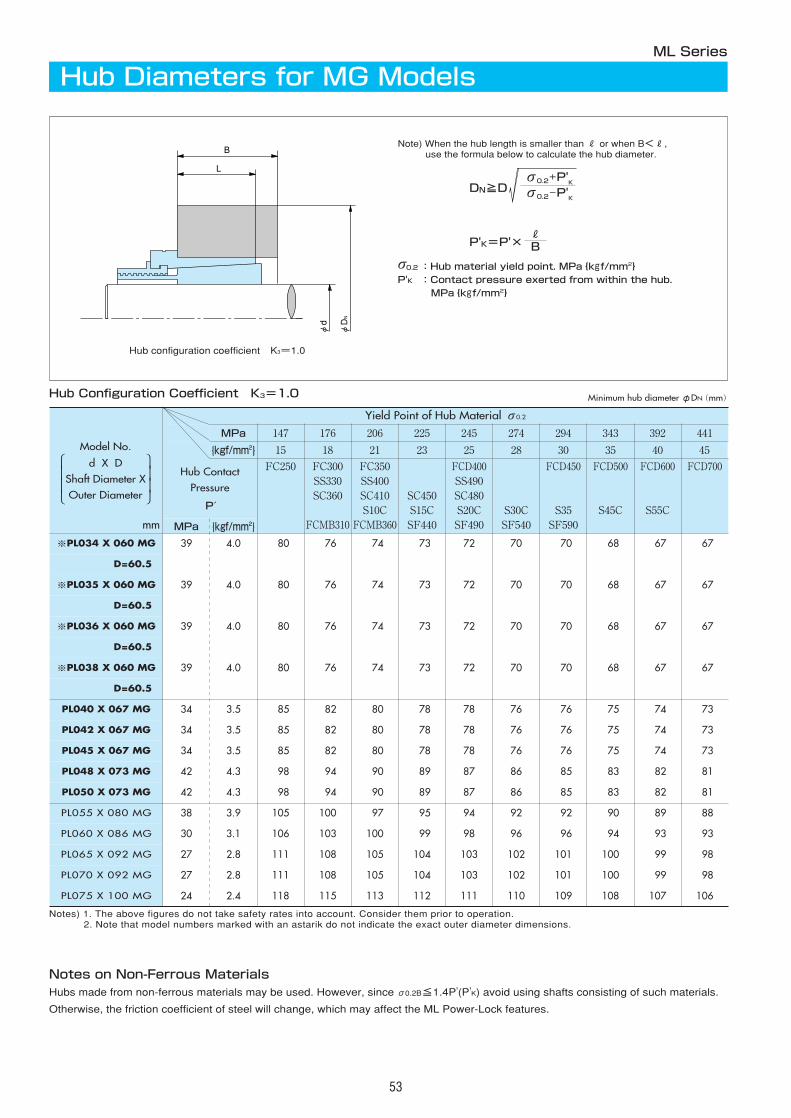
53
φd
B
L
φDN
Hub Diameters for MG ModelsML Series
Hub Configuration Coefficient K3=1.0
Hub configuration coefficient K3=1.0
Notes on Non-Ferrous MaterialsHubs made from non-ferrous materials may be used. However, since σ0.2B≦1.4P'(P'K) avoid using shafts consisting of such materials.
Otherwise, the friction coefficient of steel will change, which may affect the ML Power-Lock features.
MPa 147 176 206 225 245 274 294 343 392 441
{kgf/mm2} 15 18 21 23 25 28 30 35 40 45
Hub ContactPressure
P′
FC250 FC300SS330SC360
FCMB310
FC350SS400SC410S10C
FCMB360
SC450S15CSF440
FCD400SS490SC480S20CSF490
S30CSF540
FCD450
S35SF590
FCD500
S45C
FCD600
S55C
FCD700
MPa {kgf/mm2}
※PL034 X 060 MG
D=60.5
※PL035 X 060 MG
※PL036 X 060 MG
※PL038 X 060 MG
PL040 X 067 MG
PL042 X 067 MG
PL045 X 067 MG
PL048 X 073 MG
PL050 X 073 MG
PL055 X 080 MG
PL060 X 086 MG
PL065 X 092 MG
PL070 X 092 MG
PL075 X 100 MG
Notes) 1. The above figures do not take safety rates into account. Consider them prior to operation.2. Note that model numbers marked with an astarik do not indicate the exact outer diameter dimensions.
Yield Point of Hub Material σ0.2
39 4.0 080 076 074 073 72 70 070 068 067 067
39 4.0 080 076 074 073 72 70 070 068 067 067
39 4.0 080 076 074 073 72 70 070 068 067 067
39 4.0 080 076 074 073 72 70 070 068 067 067
34 3.5 085 082 080 078 78 76 076 075 074 073
34 3.5 085 082 080 078 78 76 076 075 074 073
34 3.5 085 082 080 078 78 76 076 075 074 073
42 4.3 098 094 090 089 87 86 085 083 082 081
42 4.3 098 094 090 089 87 86 085 083 082 081
38 3.9 105 100 097 095 94 92 092 090 089 088
30 3.1 106 103 100 099 98 96 096 094 093 093
27 2.8 111 108 105 104 103 102 101 100 099 098
27 2.8 111 108 105 104 103 102 101 100 099 098
24 2.4 118 115 113 112 111 110 109 108 107 106
Note) When the hub length is smaller than R or when B<R,use the formula below to calculate the hub diameter.
DN≧D
P'K=P'×RB
σ0.2+P'Kσ0.2-P'K
σ0.2 :Hub material yield point. MPa{kgf/mm2}P'K :Contact pressure exerted from within the hub.
MPa{kgf/mm2}
mm
D=60.5
D=60.5
D=60.5
Minimum hub diameterφDN(mm)
Model No.
d X DShaft Diameter XOuter Diameter

AS
AS
AS
AS
AS
AS
AS
ML
AS
AS
54
MA50=0.5MA MA75=0.75MA
TransmissibleTorqueMt50
TransmissibleThrustPax50
Contact Pressure TighteningTorqueMA50
TransmissibleTorqueMt75
TransmissibleThrustPax75
Contact Pressure TighteningTorqueMA75
ShaftP50
HubP'50
ShaftP75
HubP'75
N・m {kgf・m} kN {kgf} MPa {kgf/mm2} MPa {kgf/mm2} N・m {kgf/mm2} N・m {kgf・m} kN {kgf} MPa {kgf/mm2} MPa {kgf/mm2} N・m {kgf・m}
PL 005 X 016 M 3.33 0.341.27 130
89.0 9.1 23 2.3 2.65 0.27
4.90 0.5 1.86 190
132 13.533 3.4 3.92 0.4
PL 006 X 016 M 3.92 0.40
PL 007 X 021 M 11.8 1.2
3.23 330
90.0 9.2
30 3.1 8.33 0.85
16.7 1.7
5.00 510
137 14.0
46 4.7 12.7 1.3 PL 008 X 021 M 12.7 1.3
PL 009 X 021 M 14.7 1.5
PL 010 X 024 M 19.6 2.0
4.02 410
87.0 8.9
33 3.4 11.8 1.2
31.4 3.2
6.37 650
137 14.0
52 5.3 18.6 1.9 PL 011 X 024 M 21.6 2.2
PL 012 X 024 M 23.5 2.4
PL 014 X 031 M 53.9 5.5
8.04 820
93.0 9.5
41 4.2 30.4 3.1
79.4 8.1
11.9 1210
138 14.1
61 6.2 45.1 4.6 PL 015 X 031 M 58.8 6.0
PL 016 X 031 M 63.7 6.5
PL 017 X 036 M 98.0 10.0
11.6 1180
93.0 9.5
41 4.2 52.9 5.4
147 15.0
17.2 1750
137 14.0
61 6.2 78.4 8.0 PL 018 X 036 M 103 10.5
PL 019 X 036 M 108 11.0
PL 020 X 041 M 123 12.5
12.4 1270
78.0 8.0
35 3.6 64.7 6.6
181 18.5
18.8 1920
119 12.1
54 5.5 98.0 10.0PL 022 X 041 M 137 14.0
PL 024 X 041 M 147 15.0
PL 025 X 046 M 186 1915.2 1550
71.0 7.2 35 3.6 90.2 9.2
274 2822.4 2290
104 10.652 5.3 133 13.6
PL 028 X 046 M 206 21
PL 030 X 050 M 225 2315.0 1530
56.0 5.7 33 3.4 137 14.0
333 3422.5 2300
83.3 8.5 50 5.1 206 21
PL 032 X 050 M 235 24
79.0 8.1 5.90 0.6 118 12.0
81.0 8.3 19.6 2.0 124 12.7
75.0 7.7 22.5 2.3 115 11.7
82.0 8.4 34.3 3.5 130 13.3
79.0 8.1 37.2 3.8 124 12.7
90.0 9.2 87.2 8.9 133 13.6
87.0 8.9 94.1 9.6 129 13.2
90.0 9.2 152 15.5 132 13.5
87.0 8.9 162 16.5 129 13.2
74.0 7.6 206 21.0 114 11.6
73.0 7.4 216 22.0 110 11.2
67.0 6.8 314 32 99.0 10.1
52.0 5.3 353 36 78.4 8.0
Note) 1. The above figures do not take safety rates into account. Consider them prior to operation.
ML Model Tightening Torque and its EffectsML Series
Transmissible torque, thrust and contact pressure of ML
Power-Locks are all proportional to their tightening torque.
Below shows tightening torque MA at 1/2 or 3/4 of the MA
values indicated in the Model Numbers and Specifications
table. Refer to the table below when reducing your
tightening or transmissible torque and contact pressure.
Note that allowable range for MA is 1/2 MA ~1.1 MA.
Note) When the hub length is less thanror when B<r, use the formula below to calculate the hub contact pressure P'K.
P'K=P'×rB
mm
Model No.d X D
Shaft Diameter XOuter Diameter
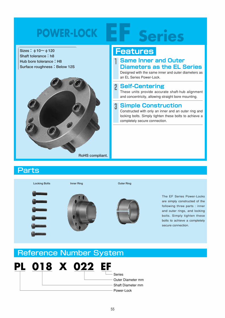
55
POWER-LOCK EF SeriesFeaturesSizes:φ10~φ120
Shaft tolerance:h8Hub bore tolerance:H8Surface roughness:Below 12S
1 Same Inner and OuterDiameters as the EL SeriesDesigned with the same inner and outer diameters asan EL Series Power-Lock.
2 Self-CenteringThese units provide accurate shaft-hub alignmentand concentricity, allowing straight bore mounting.
3 Simple ConstructionConstructed with only an inner and an outer ring andlocking bolts. Simply tighten these bolts to achieve acompletely secure connection.
Parts
Reference Number System
The EF Series Power-Locks
are simply constructed of the
following three parts : inner
and outer rings, and locking
bolts. Simply tighten these
bolts to achieve a completely
secure connection.
PL 018 X 022 EF
Shaft Diameter mm
Power-Lock
Outer Diameter mm
Series
Locking Bolts Inner Ring Outer Ring
RoHS compliant.
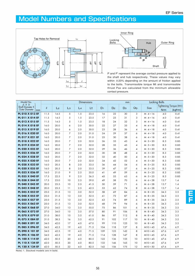
AS
AS
AS
AS
AS
AS
AS
ML
EF
AS
56
Dimensions mm Locking Bolts
R L3 Lt D2 Qty.L2 L4 D1 D3
Note) 1. Stocked models are in bold.
SizeTightening Torque (MA)
N・m {kgf・m}
PL 090 X 101 EF 34.0 42.5 19 4.0 71.5 109 123 142 8 M10×45 67.6 6.9
PL 095 X 106 EF 34.0 42.5 19 4.0 71.5 114 128 147 8 M10×45 67.6 6.9
PL 100 X 114 EF 42.0 50.5 20 4.0 80.5 122 136 155 10 M10×45 67.6 6.9
PL 110 X 124 EF 42.0 50.5 20 4.0 80.5 132 146 165 10 M10×45 67.6 6.9
PL 120 X 134 EF 42.0 50.5 22 4.0 82.5 142 156 175 12 M10×50 67.6 6.9
PL 010 X 013 EF 11.5 14.5 5 1.5 23.5 16 22 30 3 M 4×16 4.0 0.41
PL 011 X 014 EF 11.5 14.5 5 1.5 23.5 17 23 31 3 M 4×16 4.0 0.41
PL 012 X 015 EF 11.5 14.5 5 1.5 23.5 18 24 32 3 M 4×16 4.0 0.41
PL 014 X 018 EF 16.0 20.0 6 2.0 30.0 22 27 35 4 M 4×18 4.0 0.41
PL 015 X 019 EF 16.0 20.0 6 2.0 30.0 23 28 36 4 M 4×18 4.0 0.41
PL 016 X 020 EF 16.0 20.0 7 2.0 31.0 24 29 37 6 M 4×18 4.0 0.41
PL 017 X 021 EF 16.0 20.0 7 2.0 31.0 25 30 38 6 M 4×18 4.0 0.41
PL 018 X 022 EF 16.0 20.0 7 2.0 32.0 26 33 43 4 M 5×20 8.3 0.85
PL 019 X 024 EF 16.0 20.0 7 2.0 32.0 28 35 45 4 M 5×20 8.3 0.85
PL 020 X 025 EF 16.0 20.0 7 2.0 32.0 29 36 46 4 M 5×20 8.3 0.85
PL 022 X 026 EF 16.0 20.0 7 2.0 32.0 30 38 48 4 M 5×20 8.3 0.85
PL 024 X 028 EF 16.0 20.0 7 2.0 32.0 32 40 50 4 M 5×20 8.3 0.85
PL 025 X 030 EF 16.0 20.0 7 2.0 32.0 34 42 52 4 M 5×20 8.3 0.85
PL 028 X 032 EF 16.0 20.5 8 2.0 33.5 36 44 54 6 M 5×25 8.3 0.85
PL 030 X 035 EF 16.0 20.5 8 2.0 33.5 39 47 57 6 M 5×25 8.3 0.85
PL 032 X 036 EF 16.0 21.0 9 2.5 35.0 41 49 59 6 M 5×25 8.3 0.85
PL 035 X 040 EF 17.5 22.5 9 2.5 36.5 45 53 63 6 M 5×25 8.3 0.85
PL 038 X 044 EF 17.5 23.0 10 2.5 39.0 49 58 70 6 M 6×28 13.7 1.4
PL 040 X 045 EF 20.0 25.5 10 2.5 41.5 50 59 71 6 M 6×28 13.7 1.4
PL 042 X 048 EF 20.0 25.5 11 2.5 42.5 53 62 74 8 M 6×28 13.7 1.4
PL 045 X 052 EF 25.0 31.5 13 3.0 52.5 58 69 84 6 M 8×35 34.3 3.5
PL 048 X 055 EF 25.0 31.5 13 3.0 52.5 61 72 87 6 M 8×35 34.3 3.5
PL 050 X 057 EF 25.0 31.5 13 3.0 52.5 63 74 89 6 M 8×35 34.3 3.5
PL 055 X 062 EF 25.0 31.5 13 3.0 52.5 68 79 94 6 M 8×35 34.3 3.5
PL 060 X 068 EF 27.0 34.0 13 3.5 55.0 75 86 101 6 M 8×35 34.3 3.5
PL 065 X 073 EF 27.0 34.0 15 3.5 57.0 80 91 106 8 M 8×40 34.3 3.5
PL 070 X 079 EF 31.0 38.0 15 3.5 61.0 86 97 112 8 M 8×40 34.3 3.5
PL 075 X 084 EF 31.0 38.5 16 3.5 62.5 91 102 117 10 M 8×40 34.3 3.5
PL 080 X 091 EF 34.0 42.0 17 4.0 67.0 99 110 125 10 M 8×40 34.3 3.5
PL 085 X 096 EF 34.0 42.5 19 4.0 71.5 104 118 137 8 M10×45 67.6 6.9
Model Numbers and SpecificationsEF Series
Tap Holes for Removal
P and P' represent the average contact pressure applied tothe shaft and hub respectively. These values may varywithin ±20% depending on the amount of friction appliedto the bolts. Transmissible torque Mt and transmissiblethrust Pax are calculated from the minimum allowablecontact pressure.
LockingBolts
Inner Ring
Outer Ring
Shaft
Hub
mm
Model No.d X D
Shaft Diameter XOuter Diameter
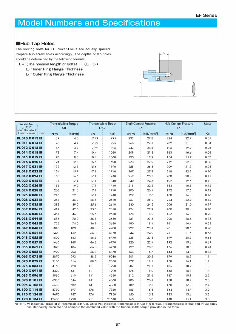
57
Transmissible Torque Transmissible Thrust Shaft Contact Pressure Hub Contact PressureMt Pax P P'
N・m {kgf・m} kN {kgf} MPa {kgf/mm2} MPa {kgf/mm2}
Mass
Kg
PL 090 X 101 EF 6330 646 141 14360 200 20.4 178 18.2 2.3
PL 095 X 106 EF 6680 682 141 14360 189 19.3 170 17.3 2.4
PL 100 X 114 EF 8790 897 176 17950 165 16.8 144 14.7 3.0
PL 110 X 124 EF 9670 987 176 17950 150 15.3 133 13.6 3.3
PL 120 X 134 EF 12600 1290 211 21540 165 16.8 148 15.1 3.8
PL 010 X 013 EF 39 4.0 7.79 795 292 29.8 224 22.9 0.04
PL 011 X 014 EF 43 4.4 7.79 795 266 27.1 209 21.3 0.04
PL 012 X 015 EF 47 4.8 7.79 795 243 24.8 195 19.9 0.04
PL 014 X 018 EF 73 7.4 10.4 1060 209 21.3 163 16.6 0.06
PL 015 X 019 EF 78 8.0 10.4 1060 195 19.9 154 15.7 0.07
PL 016 X 020 EF 124 12.7 15.6 1590 273 27.9 219 22.3 0.08
PL 017 X 021 EF 132 13.5 15.6 1590 258 26.3 209 21.3 0.08
PL 018 X 022 EF 154 15.7 17.1 1740 267 27.2 218 22.2 0.10
PL 019 X 024 EF 163 16.6 17.1 1740 252 25.7 200 20.4 0.11
PL 020 X 025 EF 171 17.4 17.1 1740 240 24.5 192 19.6 0.12
PL 022 X 026 EF 186 19.0 17.1 1740 218 22.2 184 18.8 0.12
PL 024 X 028 EF 206 21.0 17.1 1740 200 20.4 172 17.5 0.12
PL 025 X 030 EF 216 22.0 17.1 1740 192 19.6 160 16.3 0.16
PL 028 X 032 EF 353 36.0 25.6 2610 257 26.2 224 22.9 0.16
PL 030 X 035 EF 382 39.0 25.6 2610 240 24.5 206 21.0 0.19
PL 032 X 036 EF 412 42.0 25.6 2610 224 22.9 200 20.4 0.20
PL 035 X 040 EF 451 46.0 25.6 2610 178 18.2 157 16.0 0.23
PL 038 X 044 EF 686 70.0 36.1 3680 231 23.6 200 20.4 0.33
PL 040 X 045 EF 725 74.0 36.1 3680 180 18.4 161 16.4 0.33
PL 042 X 048 EF 1010 103 48.0 4900 229 23.4 201 20.5 0.40
PL 045 X 052 EF 1490 152 66.3 6770 244 24.9 211 21.5 0.65
PL 048 X 055 EF 1600 163 66.3 6770 228 23.3 199 20.3 0.68
PL 050 X 057 EF 1660 169 66.3 6770 220 22.4 192 19.6 0.69
PL 055 X 062 EF 1820 186 66.3 6770 199 20.3 176 18.0 0.74
PL 060 X 068 EF 1990 203 66.3 6770 164 16.7 144 14.7 0.86
PL 065 X 073 EF 2870 293 88.5 9030 201 20.5 179 18.3 1.1
PL 070 X 079 EF 3100 316 88.5 9030 177 18.1 158 16.1 1.2
PL 075 X 084 EF 4150 423 111 11290 207 21.1 185 18.9 1.3
PL 080 X 091 EF 4420 451 111 11290 176 18.0 155 15.8 1.7
PL 085 X 096 EF 5980 610 141 14360 212 21.6 187 19.1 2.2
Model Numbers and SpecificationsEF Series
■Hub Tap HolesThe locking bolts for EF Power-Locks are equally spaced.
Prepare hub screw holes accordingly. The depths of tap holes
should be determined by the following formula.
L=(The nominal length of bolts)-(L3+L4)
L3:Inner Ring Flange Thickness
L4:Outer Ring Flange Thickness
mm
Model No.d X D
Shaft Diameter XOuter Diameter
Note) 1. Mt indicates torque at 0 transmissible thrust, while Pax indicates transmissible thrust at 0 torque. If transmissible torque and thrust applysimultaneously calculate and compare the combined value with the transmissible torque provided in the table.
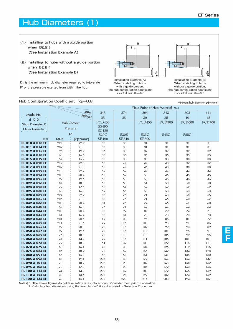
AS
AS
AS
AS
AS
AS
AS
AS
EF
AS
58
Hub Contact
Pressure
P'
FCD700
PL 090 X 101 EF 178 18.2 152PL 095 X 106 EF 170 17.3 156PL 100 X 114 EF 144 14.7 159PL 110 X 124 EF 133 13.6 169
441
45
MPa {kgf/mm2}
245 274 294 343 392
25 28 30 35 40
FCD400SS490SC480S20CSF490
S30SSF540
FCD450
S35CSF590
FCD500
S45C
FCD600
S55C
207 190 182 168 158208 193 185 172 163200 189 183 172 165208 197 192 182 174
MPakgf/mm2
PL 120 X 134 EF 148 15.1 238 223 216 203 194 187
PL 010 X 013 EF 224 22.9 38 33 31 31 31 31PL 011 X 014 EF 209 21.3 37 33 31 31 31 31PL 012 X 015 EF 195 19.9 36 33 32 32 32 32PL 014 X 018 EF 163 16.6 37 35 35 35 35 35PL 015 X 019 EF 154 15.7 38 38 38 38 38 38PL 016 X 020 EF 219 22.3 53 47 44 40 37 37PL 017 X 021 EF 209 21.3 53 47 45 40 38 38PL 018 X 022 EF 218 22.2 59 52 49 44 44 44PL 019 X 024 EF 200 20.4 58 52 50 45 45 45PL 020 X 025 EF 192 19.6 58 53 50 46 46 46PL 022 X 026 EF 184 18.8 58 53 51 50 50 50PL 024 X 028 EF 172 17.5 58 54 52 52 52 52PL 025 X 030 EF 160 16.3 59 55 53 53 53 53PL 028 X 032 EF 224 22.9 87 75 71 63 58 55PL 030 X 035 EF 206 21.0 85 76 71 65 60 57PL 032 X 036 EF 200 20.4 84 76 72 65 61 60PL 035 X 040 EF 157 16.0 76 71 69 64 64 64PL 038 X 044 EF 200 20.4 103 92 87 79 74 71PL 040 X 045 EF 161 16.4 87 81 78 73 73 73PL 042 X 048 EF 201 20.5 112 100 95 86 81 77PL 045 X 052 EF 211 21.5 129 115 108 98 91 86PL 048 X 055 EF 199 20.3 128 115 109 99 93 89PL 050 X 057 EF 192 19.6 128 116 110 101 95 91PL 055 X 062 EF 176 18.0 128 118 113 105 99 95PL 060 X 068 EF 144 14.7 122 115 111 105 101 101PL 065 X 073 EF 179 18.3 151 139 133 122 116 111PL 070 X 079 EF 158 16.1 148 138 134 125 119 115PL 075 X 084 EF 185 18.9 178 162 155 142 134 128PL 080 X 091 EF 155 15.8 167 157 151 141 135 130PL 085 X 096 EF 187 19.1 206 188 179 164 154 147
Notes) 1. The above figures do not take safety rates into account. Consider them prior to operation.2. Calculate hub diameters using the formula K3=0.8 as discussed in Selection Procedure.
Yield Point of Hub Material σ0.2
EF Series
Hub Diameters (1)
(1)Installing to hubs with a guide portion
when B≧2R
(See Installation Example A)
(2)Installing to hubs without a guide portion
when B≧2R
(See Installation Example B)
DN is the minimum hub diameter required to totolerate
P' or the pressure exerted from within the hub.
Hub Configuration Coefficient K3=0.8
mm
Minimum hub diameterφDN(mm)
Installation Example(A)When installing to hubswith a guide portion,
the hub configuration coefficientis as follows: K3=0.8
Installation Example(B)When installing to hubswithout a guide portion,
the hub configuration coefficientis as follows: K3=0.8
Model No.
d X DShaft Diameter XOuter Diameter
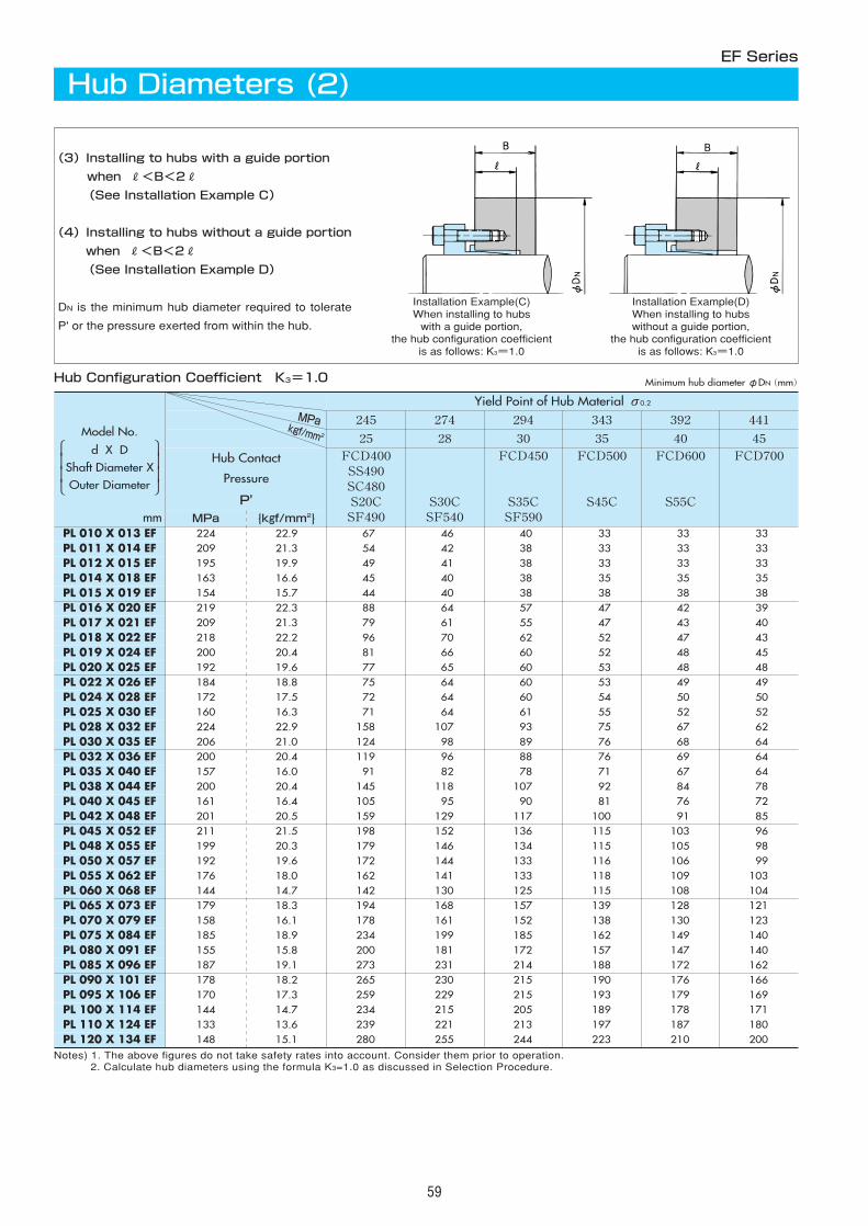
59
Hub Contact
Pressure
P'
FCD700
PL 090 X 101 EF 178 18.2 166PL 095 X 106 EF 170 17.3 169PL 100 X 114 EF 144 14.7 171PL 110 X 124 EF 133 13.6 180
441
45
MPa {kgf/mm2}
245 274 294 343 392
25 28 30 35 40
FCD400SS490SC480S20CSF490
S30CSF540
FCD450
S35CSF590
FCD500
S45C
FCD600
S55C
265 230 215 190 176259 229 215 193 179234 215 205 189 178239 221 213 197 187
MPakgf/mm2
PL 120 X 134 EF 148 15.1 280 255 244 223 210 200
PL 010 X 013 EF 224 22.9 67 46 40 33 33 33PL 011 X 014 EF 209 21.3 54 42 38 33 33 33PL 012 X 015 EF 195 19.9 49 41 38 33 33 33PL 014 X 018 EF 163 16.6 45 40 38 35 35 35PL 015 X 019 EF 154 15.7 44 40 38 38 38 38PL 016 X 020 EF 219 22.3 88 64 57 47 42 39PL 017 X 021 EF 209 21.3 79 61 55 47 43 40PL 018 X 022 EF 218 22.2 96 70 62 52 47 43PL 019 X 024 EF 200 20.4 81 66 60 52 48 45PL 020 X 025 EF 192 19.6 77 65 60 53 48 48PL 022 X 026 EF 184 18.8 75 64 60 53 49 49PL 024 X 028 EF 172 17.5 72 64 60 54 50 50PL 025 X 030 EF 160 16.3 71 64 61 55 52 52PL 028 X 032 EF 224 22.9 158 107 93 75 67 62PL 030 X 035 EF 206 21.0 124 98 89 76 68 64PL 032 X 036 EF 200 20.4 119 96 88 76 69 64PL 035 X 040 EF 157 16.0 91 82 78 71 67 64PL 038 X 044 EF 200 20.4 145 118 107 92 84 78PL 040 X 045 EF 161 16.4 105 95 90 81 76 72PL 042 X 048 EF 201 20.5 159 129 117 100 91 85PL 045 X 052 EF 211 21.5 198 152 136 115 103 96PL 048 X 055 EF 199 20.3 179 146 134 115 105 98PL 050 X 057 EF 192 19.6 172 144 133 116 106 99PL 055 X 062 EF 176 18.0 162 141 133 118 109 103PL 060 X 068 EF 144 14.7 142 130 125 115 108 104PL 065 X 073 EF 179 18.3 194 168 157 139 128 121PL 070 X 079 EF 158 16.1 178 161 152 138 130 123PL 075 X 084 EF 185 18.9 234 199 185 162 149 140PL 080 X 091 EF 155 15.8 200 181 172 157 147 140PL 085 X 096 EF 187 19.1 273 231 214 188 172 162
Yield Point of Hub Material σ0.2
Notes) 1. The above figures do not take safety rates into account. Consider them prior to operation.2. Calculate hub diameters using the formula K3=1.0 as discussed in Selection Procedure.
EF Series
Hub Diameters (2)
(3)Installing to hubs with a guide portion
when R<B<2R
(See Installation Example C)
(4)Installing to hubs without a guide portion
when R<B<2R
(See Installation Example D)
DN is the minimum hub diameter required to tolerate
P' or the pressure exerted from within the hub.
Hub Configuration Coefficient K3=1.0
mm
Minimum hub diameterφDN(mm)
Installation Example(C)When installing to hubswith a guide portion,
the hub configuration coefficientis as follows: K3=1.0
Installation Example(D)When installing to hubswithout a guide portion,
the hub configuration coefficientis as follows: K3=1.0
Model No.
d X DShaft Diameter XOuter Diameter
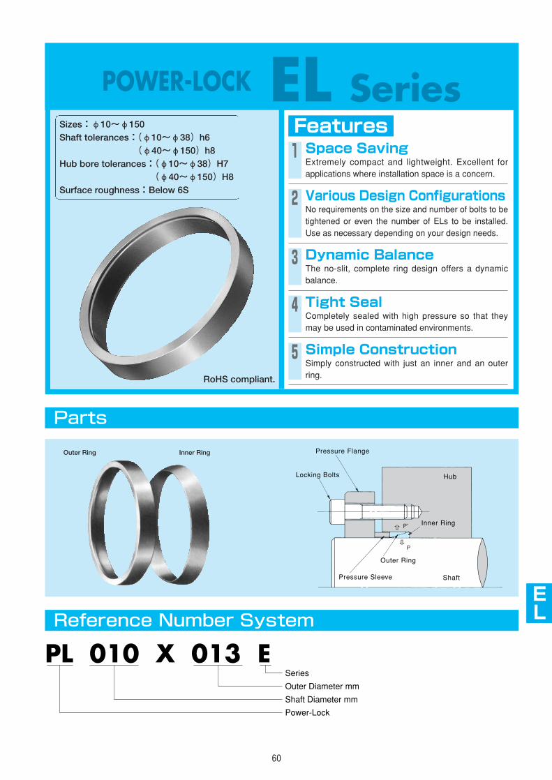
AS
AS
AS
AS
AS
AS
AS
AS
EF
EL
60
POWER-LOCK EL SeriesFeaturesSizes:φ10~φ150
Shaft tolerances:(φ10~φ38)h6(φ40~φ150)h8
Hub bore tolerances:(φ10~φ38)H7(φ40~φ150)H8
Surface roughness:Below 6S
1 Space SavingExtremely compact and lightweight. Excellent forapplications where installation space is a concern.
2 Various Design ConfigurationsNo requirements on the size and number of bolts to betightened or even the number of ELs to be installed.Use as necessary depending on your design needs.
3 Dynamic BalanceThe no-slit, complete ring design offers a dynamicbalance.
4 Tight SealCompletely sealed with high pressure so that theymay be used in contaminated environments.
5 Simple ConstructionSimply constructed with just an inner and an outerring.
Parts
Reference Number System
PL 010 X 013 E
Shaft Diameter mm
Power-Lock
Outer Diameter mm
Series
Inner RingOuter Ring Pressure Flange
Pressure Sleeve
Outer Ring
Locking Bolts
Inner Ring
Shaft
Hub
RoHS compliant.
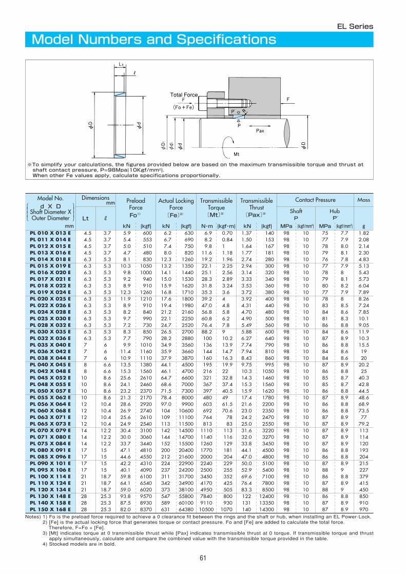
61
Notes) 1) Fo is the preload force required to achieve a 0 clearance fit between the rings and the shaft or hub, when installing an EL Power-Lock.2) [Fe] is the actual locking force that generates torque or contact pressure. Fo and [Fe] are added to calculate the total force.
Therefore, F=Fo + [Fe].3) [Mt] indicates torque at 0 transmissible thrust while [Pax] indicates transmissible thrust at 0 torque. If transmissible torque and thrust
apply simultaneously, calculate and compare the combined value with the transmissible torque provided in the table.4) Stocked models are in bold.
Dimensionsmm Preload
ForceFo1)
Actual LockingForce〔Fe〕2)
TransmissibleTorque〔Mt〕3)
TransmissibleThrust
〔Pax〕3)
Contact Pressure Mass
Lt RShaftP
HubP′
kN {kgf} kN {kgf} N・m {kgf・m} kN {kgf} MPa {kgf/mm2} MPa {kgf/mm2} gPL 010 X 013 E 4.5 3.7 5.9 600 6.2 630 6.9 0.70 1.37 140 98 10 75 7.7 1.82PL 011 X 014 E 4.5 3.7 5.4 553 6.7 690 8.2 0.84 1.50 153 98 10 77 7.9 2.08PL 012 X 015 E 4.5 3.7 5.0 510 7.4 750 9.8 1 1.64 167 98 10 78 8.0 2.14PL 013 X 016 E 4.5 3.7 4.7 480 8.0 820 11.6 1.18 1.77 181 98 10 79 8.1 2.30PL 014 X 018 E 6.3 5.3 8.1 830 12.3 1260 19.2 1.96 2.74 280 98 10 76 7.8 4.83PL 015 X 019 E 6.3 5.3 10.3 1050 13.2 1350 22.1 2.25 2.94 300 98 10 77 7.9 5.13PL 016 X 020 E 6.3 5.3 9.8 1000 14.1 1440 25.1 2.56 3.14 320 98 10 78 8 5.43PL 017 X 021 E 6.3 5.3 9.2 940 15.0 1530 28.3 2.89 3.33 340 98 10 79 8.1 5.73PL 018 X 022 E 6.3 5.3 8.9 910 15.9 1620 31.8 3.24 3.53 360 98 10 80 8.2 6.04PL 019 X 024 E 6.3 5.3 12.3 1260 16.8 1710 35.3 3.6 3.72 380 98 10 77 7.9 7.89PL 020 X 025 E 6.3 5.3 11.9 1210 17.6 1800 39.2 4 3.92 400 98 10 78 8 8.26PL 022 X 026 E 6.3 5.3 8.9 910 19.4 1980 47.0 4.8 4.31 440 98 10 83 8.5 7.24PL 024 X 028 E 6.3 5.3 8.2 840 21.2 2160 56.8 5.8 4.70 480 98 10 84 8.6 7.85PL 025 X 030 E 6.3 5.3 9.7 990 22.1 2250 60.8 6.2 4.90 500 98 10 81 8.3 10.1PL 028 X 032 E 6.3 5.3 7.2 730 24.7 2520 76.4 7.8 5.49 560 98 10 86 8.8 9.05PL 030 X 035 E 6.3 5.3 8.3 850 26.5 2700 88.2 9 5.88 600 98 10 84 8.6 11.9PL 032 X 036 E 6.3 5.3 7.7 790 28.2 2880 100 10.2 6.27 640 98 10 87 8.9 10.3PL 035 X 040 E 7 6 9.9 1010 34.9 3560 136 13.9 7.74 790 98 10 86 8.8 15.5PL 036 X 042 E 7 6 11.4 1160 35.9 3660 144 14.7 7.94 810 98 10 84 8.6 19PL 038 X 044 E 7 6 10.9 1110 37.9 3870 160 16.3 8.43 860 98 10 84 8.6 20PL 040 X 045 E 8 6.6 13.5 1380 44.1 4500 195 19.9 9.75 995 98 10 87 8.9 20.2PL 042 X 048 E 8 6.6 15.3 1560 46.1 4700 216 22 10.3 1050 98 10 86 8.8 25PL 045 X 052 E 10 8.6 25.6 2610 64.7 6600 321 32.8 14.3 1460 98 10 85 8.7 40.3PL 048 X 055 E 10 8.6 24.1 2460 68.6 7000 367 37.4 15.3 1560 98 10 85 8.7 42.8PL 050 X 057 E 10 8.6 23.2 2370 71.5 7300 397 40.5 15.9 1620 98 10 86 8.8 44.5PL 055 X 062 E 10 8.6 21.3 2170 78.4 8000 480 49 17.4 1780 98 10 87 8.9 48.6PL 056 X 064 E 12 10.4 28.6 2920 97.0 9900 603 61.5 21.6 2200 98 10 86 8.8 68.9PL 060 X 068 E 12 10.4 26.9 2740 104 10600 692 70.6 23.0 2350 98 10 86 8.8 73.5PL 063 X 071 E 12 10.4 25.6 2610 109 11100 764 78 24.2 2470 98 10 87 8.9 77PL 065 X 073 E 12 10.4 24.9 2540 113 11500 813 83 25.0 2550 98 10 87 8.9 79.2PL 070 X 079 E 14 12.2 30.4 3100 142 14500 1110 113 31.6 3220 98 10 87 8.9 113PL 071 X 080 E 14 12.2 30.0 3060 144 14700 1140 116 32.0 3270 98 10 87 8.9 114PL 075 X 084 E 14 12.2 33.7 3440 152 15500 1260 129 33.8 3450 98 10 87 8.9 120PL 080 X 091 E 17 15 47.1 4810 200 20400 1770 181 44.1 4500 98 10 86 8.8 193PL 085 X 096 E 17 15 44.6 4550 212 21600 2000 204 47.0 4800 98 10 86 8.8 204PL 090 X 101 E 17 15 42.2 4310 224 22900 2240 229 50.0 5100 98 10 87 8.9 215PL 095 X 106 E 17 15 40.1 4090 237 24200 2500 255 52.9 5400 98 10 88 9 227PL 100 X 114 E 21 18.7 59.8 6100 311 31700 3450 352 69.6 7100 98 10 86 8.8 379PL 110 X 124 E 21 18.7 64.1 6540 342 34900 4170 425 76.4 7800 98 10 87 8.9 415PL 120 X 134 E 21 18.7 59.0 6020 373 38100 4950 505 83.3 8500 98 10 88 9 450
PL 150 X 168 E 28 25.3 82.0 8370 631 64380 10500 1070 140 14300 98 10 87 8.9 970
PL 130 X 148 E 28 25.3 93.8 9570 547 55800 7840 800 122 12400 98 10 86 8.8 850PL 140 X 158 E 28 25.3 87.5 8930 589 60100 9110 930 131 13350 98 10 87 8.9 910
Total Force
EL Series
Model Numbers and Specifications
※To simplify your calculations, the figures provided below are based on the maximum transmissible torque and thrust atshaft contact pressure, P=98Mpa{10Kgf/mm2}. When other Fe values apply, calculate specifications proportionally.
mm
Model No.d X D
Shaft Diameter XOuter Diameter
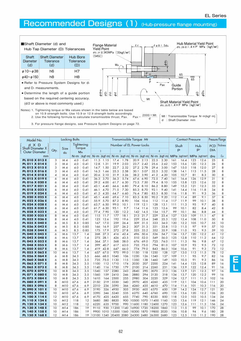
Flange MaterialYield Point
Hub Material Yield Point
Shaft Material Yield Point
GuidePortion
AS
AS
AS
AS
AS
AS
AS
AS
AS
EL
62
Notes) 1. Tightening torque or Ma values shown in the table below are basedon 10.9 strength bolts. Use 10.9 or 12.9 strength bolts accordingly.
2. Use the following formula to calculate transmissible thrust, Pax. Pax=2000×Mt
3. For pressure flange designs, see Pressure System Designs on page 72.
Locking Bolts Transmissible Torque Mt Contact Pressure Pressure Flange
Qty. SizedG
TighteningTorqueMA
Number of EL Power-Locks ShaftP
HubP′
PCDDIA
Thickness
1 2 3 4
N・m {kgf・m} N・m {kgf・m} N・m {kgf・m} N・m {kgf・m} N・m {kgf・m} MPa {kgf/mm2} MPa {kgf/mm2}
PL 010 X 013 E 3 M 4 4.0 0.41 11.3 1.15 17.4 1.78 20.9 2.13 22.5 2.30 161 16.4 123 12.6 25 8 PL 011 X 014 E 3 M 4 4.0 0.41 12.8 1.31 19.9 2.03 23.7 2.42 25.6 2.62 153 15.6 120 12.3 26 8 PL 012 X 015 E 3 M 4 4.0 0.41 14.7 1.50 22.7 2.32 27.2 2.78 29.4 3.00 147 15.0 118 12.0 27 8 PL 013 X 016 E 3 M 4 4.0 0.41 16.3 1.66 25.3 2.58 30.1 3.07 32.5 3.32 138 14.1 113 11.5 28 8 PL 014 X 018 E 4 M 4 4.0 0.41 20.6 2.10 31.9 3.26 38.2 3.90 41.2 4.20 105 10.7 81 8.3 30 8 PL 015 X 019 E 6 M 4 4.0 0.41 36.3 3.70 56.3 5.74 67.6 6.90 72.5 7.40 161 16.4 126 12.9 31 8 PL 016 X 020 E 6 M 4 4.0 0.41 39.2 4.00 61.7 6.30 73.5 7.50 79.4 8.10 155 15.8 123 12.6 32 8 PL 017 X 021 E 6 M 4 4.0 0.41 43.1 4.40 66.6 6.80 79.4 8.10 86.2 8.80 149 15.2 121 12.3 33 8 PL 018 X 022 E 6 M 4 4.0 0.41 46.1 4.70 71.5 7.30 85.3 8.70 92.1 9.40 141 14.4 116 11.8 34 8 PL 019 X 024 E 6 M 4 4.0 0.41 41.2 4.20 64.7 6.60 76.4 7.80 83.3 8.50 116 11.8 91 9.3 36 8 PL 020 X 025 E 6 M 4 4.0 0.41 45.1 4.60 69.6 7.10 83.3 8.50 90.2 9.20 112 11.4 89 9.1 37 8 PL 022 X 026 E 6 M 4 4.0 0.41 55.9 5.70 87.2 8.90 104 10.6 112 11.4 117 11.9 99 10.1 38 8 PL 024 X 028 E 6 M 4 4.0 0.41 63.7 6.50 99.0 10.1 119 12.1 128 13.1 111 11.3 95 9.7 40 8 PL 025 X 030 E 6 M 4 4.0 0.41 61.7 6.30 95.1 9.7 114 11.6 123 12.6 99 10.1 82 8.4 42 8 PL 028 X 032 E 6 M 4 4.0 0.41 77.4 7.90 120 12.2 142 14.5 154 15.7 99 10.1 86 8.8 44 8 PL 030 X 035 E 8 M 4 4.0 0.41 115 11.7 177 18.1 213 21.7 229 23.4 127 13.0 109 11.1 47 8 PL 032 X 036 E 8 M 4 4.0 0.41 123 12.6 192 19.6 229 23.4 248 25.3 122 12.4 108 11.0 50 8 PL 035 X 040 E 6 M 5 8.3 0.85 167 17.0 259 26.4 309 31.5 333 34.0 120 12.2 105 10.7 55 10PL 036 X 042 E 6 M 5 8.3 0.85 166 16.9 257 26.2 307 31.3 331 33.8 113 11.5 97 9.9 57 10PL 038 X 044 E 6 M 5 8.3 0.85 175 17.9 272 27.8 325 33.2 352 35.9 108 11.0 93 9.5 59 10PL 040 X 045 E 6 M 6 13.7 1.4 268 27.3 416 42.4 496 50.6 536 54.7 134 13.7 120 12.2 61 12PL 042 X 048 E 6 M 6 13.7 1.4 275 28.1 426 43.5 510 52.0 549 56.0 125 12.8 110 11.2 64 12PL 045 X 052 E 8 M 6 13.7 1.4 364 37.1 568 58.0 676 69.0 725 74.0 111 11.3 96 9.8 67 12PL 048 X 055 E 8 M 6 13.7 1.4 399 40.7 617 63.0 735 75.0 794 81.0 107 10.9 93 9.5 72 12PL 050 X 057 E 8 M 6 13.7 1.4 419 42.8 647 66.0 774 79.0 843 86.0 104 10.6 91 9.3 73 12PL 055 X 062 E 10 M 6 13.7 1.4 657 67.0 970 99.0 1150 118 1250 128 127 13.0 113 11.5 78 12PL 056 X 064 E 6 M 8 34.3 3.5 666 68.0 1040 106 1230 126 1340 137 109 11.1 95 9.7 82 16PL 060 X 068 E 6 M 8 34.3 3.5 735 75.0 1130 115 1350 138 1460 149 103 10.5 91 9.3 86 16PL 063 X 071 E 8 M 8 34.3 3.5 1100 112 1710 174 2030 207 2200 224 141 14.4 125 12.8 89 16PL 065 X 073 E 8 M 8 34.3 3.5 1140 116 1750 179 2100 214 2260 231 136 13.9 122 12.4 91 16PL 070 X 079 E 10 M 8 34.3 3.5 1540 157 2380 243 2840 290 3070 313 136 13.9 121 12.3 97 16PL 071 X 080 E 10 M 8 34.3 3.5 1560 159 2410 246 2880 294 3120 318 134 13.7 120 12.2 99 16PL 075 X 084 E 10 M 8 34.3 3.5 1610 164 2500 255 2980 304 3220 329 124 12.7 111 11.3 102 16PL 080 X 091 E 8 M10 67.6 6.9 2150 219 3330 340 3970 405 4260 435 119 12.1 104 10.6 111 20PL 085 X 096 E 8 M10 67.6 6.9 2310 236 3590 366 4260 435 4610 470 114 11.6 101 10.3 116 20PL 090 X 101 E 10 M10 67.6 6.9 3190 326 4950 505 5930 605 6370 650 139 14.2 124 12.7 121 20PL 095 X 106 E 10 M10 67.6 6.9 3390 346 5240 535 6270 640 6760 690 133 13.6 120 12.2 126 20PL 100 X 114 E 12 M10 67.6 6.9 4170 425 6420 655 7740 790 8330 850 118 12.0 103 10.5 134 24PL 110 X 124 E 10 M12 118 12 5680 580 8820 900 10500 1070 11400 1160 133 13.6 119 12.1 146 24PL 120 X 134 E 10 M12 118 12 6220 635 9700 990 11600 1180 12400 1270 123 12.6 111 11.3 156 24PL 130 X 148 E 10 M14 186 19 9110 930 11200 1140 16900 1720 18200 1860 113 11.5 99 10.1 170 28PL 140 X 158 E 10 M14 186 19 9900 1010 15300 1560 18300 1870 19800 2020 106 10.8 94 9.6 180 28PL 150 X 168 E 12 M14 186 19 13100 1340 20400 2080 24300 2480 26300 2680 123 12.5 110 11.2 190 28
■Shaft Diameter (d) and
Hub Tap Diameter (D) Tolerances
● Refer to Pressure System Designs for d1
and D1 measurements.
● Determine the length of a guide portion
based on the required centering accuracy.
(d/2 or above is most commonly used.)
ShaftDiameter(d)
Shaft DiameterTolerance(d)
Hub BoreTolerance(D)
φ10~φ38 h6 H7
φ40~φ150 h8 H8
dMt:Transmissible Torque N・m{kgf・m}d :Shaft Diameter mm
dPB rF
EL Series
Recommended Designs (1) (Hub-pressure flange mounting)
mm
Model No.d X D
Shaft Diameter XOuter Diameter
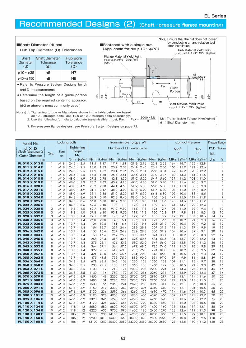
01 M08 24.5 2.5 11.5 1.17 17.7 1.81 21.2 2.16 22.8 2.33 164 16.7 125 12.8 401 M08 24.5 2.5 13.0 1.33 20.2 2.06 24.1 2.46 26.1 2.66 156 15.9 121 12.6 401 M08 24.5 2.5 14.9 1.52 23.1 2.36 27.5 2.81 29.8 3.04 149 15.2 120 12.2 401 M08 24.5 2.5 16.5 1.68 25.6 2.61 30.5 3.11 33.0 3.37 140 14.3 114 11.6 401 M10 48.0 4.9 27.2 2.78 42.1 4.30 51.0 5.20 54.9 5.60 139 14.2 108 11.0 501 M10 48.0 4.9 25.7 2.62 40.2 4.10 47.0 4.80 51.0 5.20 114 11.6 90 9.2 501 M10 48.0 4.9 28.2 2.88 44.1 4.50 51.9 5.30 56.8 5.80 111 11.3 88 9.0 501 M10 48.0 4.9 31.1 3.17 48.0 4.90 57.8 5.90 61.7 6.30 108 11.0 87 8.9 501 M10 48.0 4.9 33.1 3.38 51.0 5.20 61.7 6.30 66.6 6.80 102 10.4 83 8.5 501 M12 84.3 8.6 52.9 5.40 82.3 8.40 98.0 10.0 106 10.8 147 15.0 117 11.9 701 M12 84.3 8.6 56.8 5.80 82.2 9.00 106 10.8 114 11.6 143 14.6 115 11.7 701 M12 84.3 8.6 69.6 7.10 108 11.0 128 13.1 139 14.2 144 14.7 122 12.4 703 M05 09.8 1.0 62.7 6.40 97.0 9.90 116 11.8 124 12.7 108 11.0 92 9.4 11 1003 M05 09.8 1.0 59.8 6.10 93.1 9.50 111 11.3 120 12.2 97 9.9 81 8.3 12 1003 M06 13.7 1.4 92.1 9.40 143 14.6 172 17.5 185 18.9 119 12.1 104 10.6 14 1203 M06 13.7 1.4 96.0 9.80 148 15.1 177 18.1 191 19.5 107 10.9 91 9.3 16 1203 M06 13.7 1.4 104 10.6 161 16.4 192 19.6 208 21.2 102 10.4 90 9.2 16 1204 M06 13.7 1.4 154 15.7 239 24.4 285 29.1 309 31.5 111 11.3 97 9.9 19 1204 M06 13.7 1.4 153 15.6 237 24.2 282 28.8 306 31.2 104 10.6 89 9.1 20 1204 M06 13.7 1.4 163 16.6 252 25.7 300 30.6 324 33.1 100 10.2 86 8.8 22 1206 M06 13.7 1.4 268 27.3 417 42.5 495 50.5 534 54.5 134 13.7 120 12.2 24 1206 M06 13.7 1.4 275 28.1 426 43.5 510 52.0 549 56.0 125 12.8 110 11.2 26 1208 M06 13.7 1.4 364 37.1 564 57.5 671 68.5 725 74.0 111 11.3 96 9.8 29 1208 M06 13.7 1.4 397 40.5 617 63.0 735 75.0 794 81.0 107 10.9 93 9.5 32 1208 M06 13.7 1.4 421 43.0 652 66.5 774 79.0 843 86.0 104 10.6 91 9.3 34 1208 M06 13.7 1.4 475 48.5 735 75.0 882 90.0 951 97.0 97 9.9 86 8.8 39 1206 M08 34.3 3.5 671 68.5 1040 106 1230 126 1350 138 109 11.1 95 9.7 38 1606 M08 34.3 3.5 730 74.5 1130 115 1350 138 1460 149 103 10.5 91 9.3 42 1608 M08 34.3 3.5 1100 112 1710 174 2030 207 2200 224 141 14.4 125 12.8 45 1608 M08 34.3 3.5 1140 116 1750 179 2100 214 2260 231 136 13.9 122 12.4 47 1606 M10 67.6 6.9 1450 148 2250 230 2700 275 2910 297 128 13.1 114 11.6 50 2006 M10 67.6 6.9 1480 151 2280 233 2730 279 2950 301 127 13.0 113 11.5 51 2006 M10 67.6 6.9 1530 156 2360 241 2820 288 3050 311 119 12.1 106 10.8 55 2008 M10 67.6 6.9 2150 219 3330 340 3970 405 4310 440 119 12.1 104 10.6 60 2008 M10 67.6 6.9 2130 236 3590 366 4260 435 4610 470 114 11.6 101 10.3 65 2010 M10 67.6 6.9 3190 326 4950 505 5930 605 6370 650 139 14.2 124 12.7 70 2010 M10 67.6 6.9 3390 346 5240 535 6270 640 6760 690 133 13.6 120 12.2 75 2012 M10 67.6 6.9 4170 425 6420 655 7740 790 8330 850 118 12.0 103 10.5 80 2010 M12 0118 12 5680 580 8820 900 10500 1070 11400 1160 133 13.6 119 12.1 88 2410 M12 0118 12 6220 635 9700 990 11600 1180 12400 1270 123 12.6 111 11.3 98 2410 M14 0186 19 9110 930 14100 1440 16900 1720 18200 1860 113 11.5 99 10.1 108 2810 M14 0186 19 9900 1010 15300 1560 18300 1870 19800 2020 106 10.8 94 9.6 118 2812 M14 0186 19 13100 1340 20400 2080 24300 2480 26300 2680 123 12.5 110 11.2 128 28
Locking Bolts Transmissible Torque Mt Contact Pressure Pressure Flange
Qty. SizedG
TighteningTorqueMA
Number of EL Power-Locks ShaftP
HubP′
PCD
DIA
Thickness
1 2 3 4
N・m {kgf・m} N・m {kgf・m} N・m {kgf・m} N・m {kgf・m} N・m {kgf・m} MPa {kgf/mm2} MPa {kgf/mm2}
PL 010 X 013 EPL 011 X 014 EPL 012 X 015 EPL 013 X 016 EPL 014 X 018 EPL 015 X 019 EPL 016 X 020 EPL 017 X 021 EPL 018 X 022 EPL 019 X 024 EPL 020 X 025 EPL 022 X 026 EPL 024 X 028 EPL 025 X 030 EPL 028 X 032 EPL 030 X 035 EPL 032 X 036 EPL 035 X 040 EPL 036 X 042 EPL 038 X 044 EPL 040 X 045 EPL 042 X 048 EPL 045 X 052 EPL 048 X 055 EPL 050 X 057 EPL 055 X 062 EPL 056 X 064 EPL 060 X 068 EPL 063 X 071 EPL 065 X 073 EPL 070 X 079 EPL 071 X 080 EPL 075 X 084 EPL 080 X 091 EPL 085 X 096 EPL 090 X 101 EPL 095 X 106 EPL 100 X 114 EPL 110 X 124 EPL 120 X 134 EPL 130 X 148 EPL 140 X 158 EPL 150 X 168 E
dPS rF
63
EL Series
Recommended Designs (2) (Shaft-pressure flange mounting)
Flange Material Yield Point
Hub Material Yield Point
Note) Ensure that the nut does not loosen by conducting an anti-rotation test after installation.
Shaft Material Yield Point
GuidePortion
mm
Notes) 1. Tightening torque or Ma values shown in the table below are basedon 10.9 strength bolts. Use 10.9 or 12.9 strength bolts accordingly.
2. Use the following formula to calculate transmissible thrust, Pax. Pax=2000×Mt
3. For pressure flange designs, see Pressure System Designs on page 72.
■Shaft Diameter (d) and
Hub Tap Diameter (D) Tolerances
● Refer to Pressure System Designs for d1
and D1 measurements.
● Determine the length of a guide portion
based on the required centering accuracy.
(d/2 or above is most commonly used.)
ShaftDiameter(d)
Shaft DiameterTolerance(d)
Hub BoreTolerance(D)
φ10~φ38 h6 H7
φ40~φ150 h8 H8
d
■Fastened with a single nut.(Applicable for d=φ10~φ22)
Model No.d X D
Shaft Diameter XOuter Diameter
Mt:Transmissible Torque N・m{kgf・m}d :Shaft Diameter mm
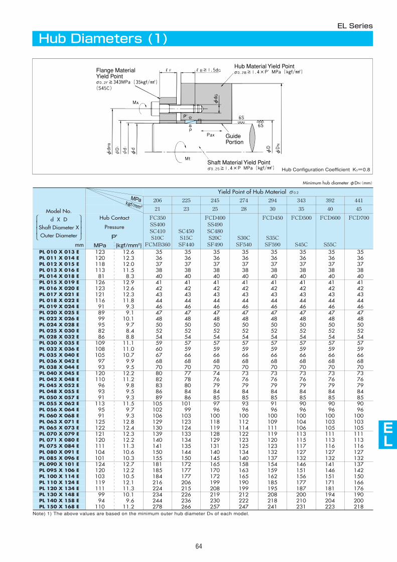
206 225 245 274 294 343 392 441
21 23 25 28 30 35 40 45
Hub Contact
Pressure
P'
FC350SS400SC410S10C
FCMB360
SC450 S15CSF440
FCD400SS490SC480 S20CSF490
S30CSF540
FCD450
S35CSF590
FCD500
S45C
FCD600
S55C
FCD700
PL 010 X 013 E 123 12.6 35 35 35 35 35 35 35 35PL 011 X 014 E 120 12.3 36 36 36 36 36 36 36 36PL 012 X 015 E 118 12.0 37 37 37 37 37 37 37 37PL 013 X 016 E 113 11.5 38 38 38 38 38 38 38 38PL 014 X 018 E 81 8.3 40 40 40 40 40 40 40 40PL 015 X 019 E 126 12.9 41 41 41 41 41 41 41 41PL 016 X 020 E 123 12.6 42 42 42 42 42 42 42 42PL 017 X 021 E 121 12.3 43 43 43 43 43 43 43 43PL 018 X 022 E 116 11.8 44 44 44 44 44 44 44 44PL 019 X 024 E 91 9.3 46 46 46 46 46 46 46 46PL 020 X 025 E 89 9.1 47 47 47 47 47 47 47 47PL 022 X 026 E 99 10.1 48 48 48 48 48 48 48 48PL 024 X 028 E 95 9.7 50 50 50 50 50 50 50 50PL 025 X 030 E 82 8.4 52 52 52 52 52 52 52 52PL 028 X 032 E 86 8.8 54 54 54 54 54 54 54 54PL 030 X 035 E 109 11.1 59 57 57 57 57 57 57 57PL 032 X 036 E 108 11.0 60 59 59 59 59 59 59 59PL 035 X 040 E 105 10.7 67 66 66 66 66 66 66 66PL 036 X 042 E 97 9.9 68 68 68 68 68 68 68 68PL 038 X 044 E 93 9.5 70 70 70 70 70 70 70 70PL 040 X 045 E 120 12.2 80 77 74 73 73 73 73 73PL 042 X 048 E 110 11.2 82 78 76 76 76 76 76 76PL 045 X 052 E 96 9.8 83 80 79 79 79 79 79 79PL 048 X 055 E 93 9.5 86 84 84 84 84 84 84 84PL 050 X 057 E 91 9.3 89 86 85 85 85 85 85 85
PL 130 X 148 E 99 10.1 234 226 219 212 208 200 194 190
PL 150 X 168 E 110 11.2 278 266 257 247 241 231 223 218
PL 055 X 062 E 113 11.5 105 101 97 93 91 90 90 90PL 056 X 064 E 95 9.7 102 99 96 96 96 96 96 96PL 060 X 068 E 91 9.3 106 103 100 100 100 100 100 100 PL 063 X 071 E 125 12.8 129 123 118 112 109 104 103 103 PL 065 X 073 E 122 12.4 130 124 119 114 111 106 105 105 PL 070 X 079 E 121 12.3 139 133 128 122 119 113 111 111 PL 071 X 080 E 120 12.2 140 134 129 123 120 115 113 113 PL 075 X 084 E 111 11.3 141 135 131 125 123 117 116 116 PL 080 X 091 E 104 10.6 150 144 140 134 132 127 127 127 PL 085 X 096 E 101 10.3 155 150 145 140 137 132 132 132 PL 090 X 101 E 124 12.7 181 172 165 158 154 146 141 137 PL 095 X 106 E 120 12.2 185 177 170 163 159 151 146 142 PL 100 X 114 E 103 10.5 184 177 172 165 162 156 151 150 PL 110 X 124 E 119 12.1 216 206 199 190 185 177 171 166 PL 120 X 134 E 111 11.3 224 215 208 199 195 187 181 176
PL 140 X 158 E 94 9.6 244 236 230 222 218 210 204 200
MPa {kgf/mm2}
Yield Point of Hub Material σ0.2
AS
AS
AS
AS
AS
AS
AS
AS
AS
EL
64
Flange MaterialYield Point
Hub Material Yield Point
Shaft Material Yield Point
GuidePortion
EL Series
Hub Diameters (1)
Note) 1) The above values are based on the minimum outer hub diameter DN of each model.
mm
Minimum hub diameterφDN(mm)
MPakgf/mm2
Model No.
d X DShaft Diameter XOuter Diameter
Hub Configuration Coefficient K3=0.8
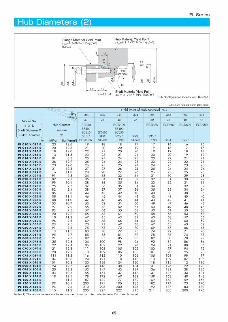
65
― 21 19 18 18 17 17 16 16 15― 22 21 20 20 19 19 18 17 17― 23 22 21 20 20 19 19 18 18― 24 23 23 21 21 20 20 19 19― 26 25 24 24 23 23 22 21 2128 26 25 24 24 23 23 22 22 2129 27 26 25 25 24 24 23 23 2330 29 27 27 26 25 25 24 24 2431 29 28 28 27 26 26 25 25 25― 37 34 33 32 31 31 30 29 28― 38 35 34 33 32 32 31 30 29― 40 38 36 35 34 33 32 31 3142 39 37 36 35 34 34 33 32 3242 40 38 37 37 36 35 35 34 3450 46 44 43 42 40 40 38 38 3752 48 46 45 44 43 42 41 40 4053 49 47 46 45 44 43 42 41 4161 56 53 52 51 50 49 47 46 4662 57 55 53 52 51 50 49 48 4764 60 57 56 55 53 53 51 50 50― 69 65 63 61 59 58 56 54 53― 71 67 65 63 61 60 58 57 5679 73 69 68 66 64 63 62 60 5982 76 73 71 69 68 67 65 63 6284 79 75 73 72 70 69 67 66 6590 84 80 78 77 75 74 72 71 7096 90 85 83 81 79 78 76 74 73101 94 89 87 85 83 82 80 78 77― 112 104 100 98 94 92 89 86 84― 113 106 102 99 96 94 91 88 86― 119 111 108 105 102 100 97 94 92― 120 113 109 106 103 101 98 95 93― 122 116 112 110 106 105 101 99 97
143 132 124 121 118 115 113 109 107 105149 137 130 126 124 120 118 115 112 110― 159 148 143 138 134 131 126 122 120― 163 153 147 143 139 136 131 128 125
178 164 155 151 147 143 141 137 134 131― 190 178 172 167 162 159 153 149 146― 199 187 182 177 172 169 163 159 156
228 211 200 194 190 185 182 177 173 170237 221 210 205 200 195 192 187 183 180273 249 235 227 222 215 211 205 200 196
Flange Material Yield Point Hub Material Yield Point
Shaft Material Yield Point
Guide Portion
Note) 1) The above values are based on the minimum outer hub diameter DN of each model.
206 225 245 274 294 343 392 441
21 23 25 28 30 35 40 45
Hub Contact
Pressure
P'
FC350SS400SC410S10C
FCMB360
SC450 S15CSF440
FCD400SS490SC480 S20CSF490
S30CSF540
FCD450
S35CSF590
FCD500
S45C
FCD600
S55C
FCD700
PL 010 X 013 EPL 011 X 014 EPL 012 X 015 EPL 013 X 016 EPL 014 X 018 EPL 015 X 019 EPL 016 X 020 EPL 017 X 021 EPL 018 X 022 EPL 019 X 024 EPL 020 X 025 EPL 022 X 026 EPL 024 X 028 EPL 025 X 030 EPL 028 X 032 EPL 030 X 035 EPL 032 X 036 EPL 035 X 040 EPL 036 X 042 EPL 038 X 044 EPL 040 X 045 EPL 042 X 048 EPL 045 X 052 EPL 048 X 055 EPL 050 X 057 E
PL 130 X 148 E
PL 150 X 168 E
PL 055 X 062 EPL 056 X 064 EPL 060 X 068 EPL 063 X 071 EPL 065 X 073 EPL 070 X 079 EPL 071 X 080 EPL 075 X 084 EPL 080 X 091 EPL 085 X 096 EPL 090 X 101 EPL 095 X 106 EPL 100 X 114 EPL 110 X 124 EPL 120 X 134 E
PL 140 X 158 E
EL Series
Hub Diameters (2)
mm
Hub Configuration Coefficient K3=0.6
Minimum hub diameterφDN(mm)
Yield Point of Hub Material σ0.2
MPa {kgf/mm2}123 12.6 19 18 18 17 17 16 16 15120 12.6 21 20 20 19 19 18 17 17118 12.0 22 21 20 20 19 19 18 18113 11.5 23 23 21 21 20 20 19 1981 8.3 25 24 24 23 23 22 21 21
126 12.9 25 24 24 23 23 22 22 21123 12.6 26 25 25 24 24 23 23 23121 12.3 27 27 26 25 25 24 24 24116 11.8 28 28 27 26 26 25 25 2591 9.3 34 33 32 31 31 30 29 2889 9.1 35 34 33 32 32 31 30 2999 10.1 38 36 35 34 33 32 31 3195 9.7 37 36 35 34 34 33 32 3282 8.4 38 37 37 36 35 35 34 3486 8.8 44 43 42 40 40 38 38 37
109 11.1 46 45 44 43 42 41 40 40108 11.0 47 46 45 44 43 42 41 41105 10.7 53 52 51 50 49 47 46 4697 9.9 55 53 52 51 50 49 48 4793 9.5 57 56 55 53 53 51 50 50
120 12.2 65 63 61 59 58 56 54 53110 11.2 67 65 63 61 60 58 57 5696 9.8 69 68 66 64 63 62 60 5993 9.5 73 71 69 68 67 65 63 6291 9.3 75 73 72 70 69 67 66 65
113 11.5 80 78 77 75 74 72 71 7095 9.7 85 83 81 79 78 76 74 7391 9.3 89 87 85 83 82 80 78 77
125 12.8 104 100 98 94 92 89 86 84122 12.4 106 102 99 96 94 91 88 86121 12.3 111 108 105 102 100 97 94 92120 12.2 113 109 106 103 101 98 95 93111 11.3 116 112 110 106 105 101 99 97104 10.6 124 121 118 115 113 109 107 105101 10.3 130 126 124 120 118 115 112 110124 12.7 148 143 138 134 131 126 122 120120 12.2 153 147 143 139 136 131 128 125103 10.5 155 151 147 143 141 137 134 131119 12.1 178 172 167 162 159 153 149 146111 11.3 187 182 177 172 169 163 159 15699 10.1 200 194 190 185 182 177 173 17094 9.6 210 205 200 195 192 187 183 180
110 11.2 235 227 222 215 211 205 200 196
MPakgf/mm2
Model No.
d X DShaft Diameter XOuter Diameter
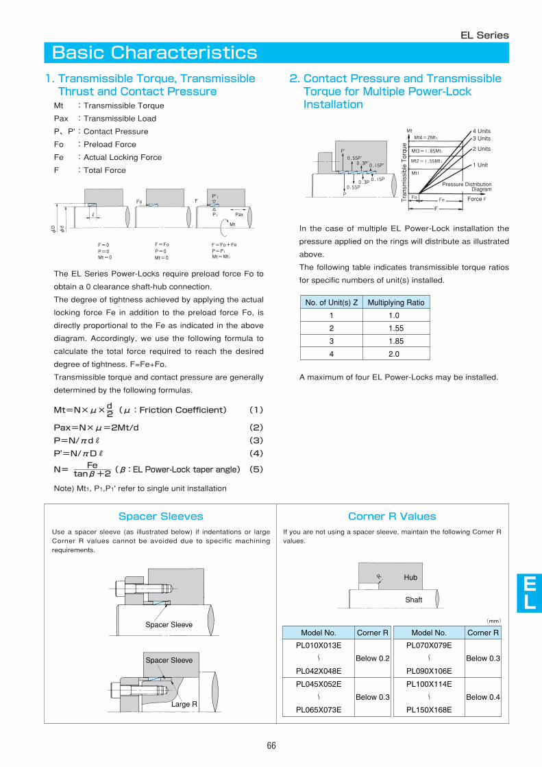
AS
AS
AS
AS
AS
AS
AS
AS
AS
EL
66
EL Series
1. Transmissible Torque, TransmissibleThrust and Contact Pressure
Mt :Transmissible Torque
Pax :Transmissible Load
P、P':Contact Pressure
Fo :Preload Force
Fe :Actual Locking Force
F :Total Force
The EL Series Power-Locks require preload force Fo to
obtain a 0 clearance shaft-hub connection.
The degree of tightness achieved by applying the actual
locking force Fe in addition to the preload force Fo, is
directly proportional to the Fe as indicated in the above
diagram. Accordingly, we use the following formula to
calculate the total force required to reach the desired
degree of tightness. F=Fe+Fo.
Transmissible torque and contact pressure are generally
determined by the following formulas.
Mt=N×μ× (μ:Friction Coefficient) (1)
Pax=N×μ=2Mt/d (2)
P=N/πdR (3)
P'=N/πDR (4)
N= (β:EL Power-Lock taper angle)(5)
Note) Mt1, P1,P1' refer to single unit installation
Fetanβ+2
d2
2. Contact Pressure and TransmissibleTorque for Multiple Power-LockInstallation
In the case of multiple EL Power-Lock installation the
pressure applied on the rings will distribute as illustrated
above.
The following table indicates transmissible torque ratios
for specific numbers of unit(s) installed.
A maximum of four EL Power-Locks may be installed.
No. of Unit(s) Z
1
2
3
4
Multiplying Ratio
1.0
1.55
1.85
2.0
Tra
nsm
issi
ble
Tor
que
Force
4 Units3 Units
2 Units
1 Unit
Pressure DistributionDiagram
Basic Characteristics
Spacer Sleeves
Use a spacer sleeve (as illustrated below) if indentations or largeCorner R values cannot be avoided due to specific machiningrequirements.
Corner R Values
If you are not using a spacer sleeve, maintain the following Corner Rvalues.
Spacer Sleeve
Spacer Sleeve
Large R
Model No.
PL010X013E
PL042X048E
Below 0.2
Below 0.3
PL045X052E
PL065X073E
Corner R
〜�
〜�
Model No.
PL070X079E
PL090X106E
Below 0.3
Below 0.4
PL100X114E
PL150X168E
Corner R
〜�
〜�
Hub
Shaft
(mm)
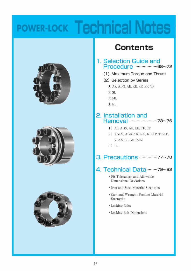
67
POWER-LOCK Technical Notes
1. Selection Guide andProcedure ………………68~72
(1)Maximum Torque and Thrust
(2)Selection by Series
① AS, ADN, AE, KE, RE, EF, TF
② SL
③ ML
④ EL
2. Installation andRemoval……………………73~761)AS, ADN, AE, KE, TF, EF
2)AS-SS, AS-KP, KE-SS, KE-KP, TF-KP,
RE-SS, SL, ML(MG)
3)EL
3. Precautions ……………77~78
4. Technical Data………79~82・Fit Tolerances and AllowableDimensional Deviations
・Iron and Steel Material Strengths
・Cast and Wrought Product MaterialStrengths
・Locking Bolts
・Locking Bolt Dimensions
Contents
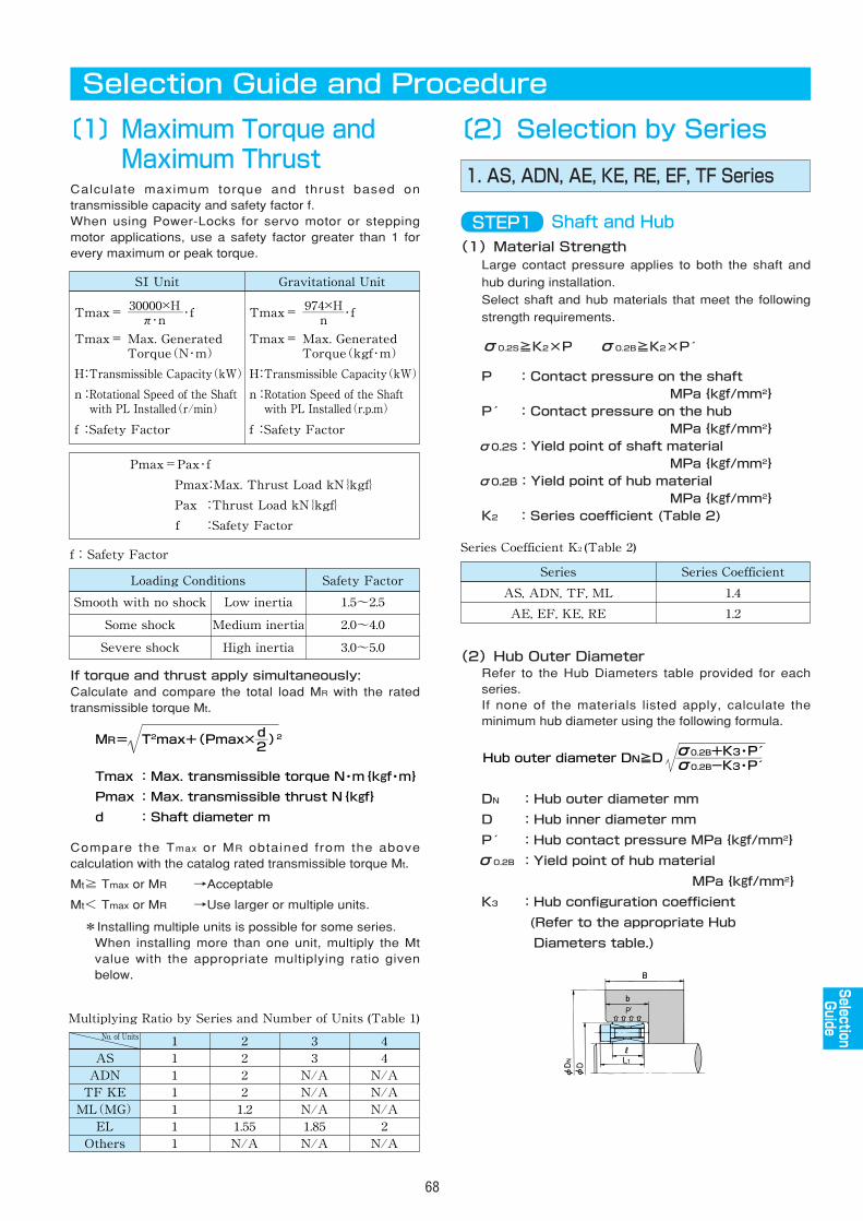
68
Selection Guide and Procedure
〔1〕Maximum Torque andMaximum Thrust
〔2〕Selection by Series
1. AS, ADN, AE, KE, RE, EF, TF SeriesCalculate maximum torque and thrust based ontransmissible capacity and safety factor f.When using Power-Locks for servo motor or steppingmotor applications, use a safety factor greater than 1 forevery maximum or peak torque. (1)Material Strength
Large contact pressure applies to both the shaft and
hub during installation.
Select shaft and hub materials that meet the following
strength requirements.
σ0.2S≧K2×P σ0.2B≧K2×P
P :Contact pressure on the shaftMPa{kgf/mm2}
P :Contact pressure on the hubMPa{kgf/mm2}
σ0.2S:Yield point of shaft materialMPa{kgf/mm2}
σ0.2B:Yield point of hub materialMPa{kgf/mm2}
K2 :Series coefficient (Table 2)
(2)Hub Outer DiameterRefer to the Hub Diameters table provided for eachseries.If none of the materials listed apply, calculate theminimum hub diameter using the following formula.
DN :Hub outer diameter mm
D :Hub inner diameter mm
P :Hub contact pressure MPa{kgf/mm2}
σ0.2B :Yield point of hub material
MPa{kgf/mm2}
K3 :Hub configuration coefficient
(Refer to the appropriate Hub
Diameters table.)
If torque and thrust apply simultaneously:Calculate and compare the total load MR with the ratedtransmissible torque Mt.
Compare the Tmax or MR obtained from the abovecalculation with the catalog rated transmissible torque Mt.
Mt≧ Tmax or MR →Acceptable
Mt< Tmax or MR →Use larger or multiple units.
*Installing multiple units is possible for some series.When installing more than one unit, multiply the Mtvalue with the appropriate multiplying ratio givenbelow.
SⅠ Unit Gravitational Unit
Tmax= ――――・f
Pmax=Pax・f�
Pmax:Max. Thrust Load kN{kgf}�
Pax :Thrust Load kN{kgf}�
f :Safety Factor
Tmax= Max. Generated� Torque(N・m)�
H:Transmissible Capacity(kW)�
n:Rotational Speed of the Shaft� with PL Installed(r/min)�
f :Safety Factor
30000×H�π・n
Tmax= ―――・f
Tmax= Max. Generated� Torque(kgf・m)�
H:Transmissible Capacity(kW)�
n:Rotation Speed of the Shaft� with PL Installed(r.p.m)�
f :Safety Factor
974×H�n
f:Safety Factor
Loading Conditions Safety Factor
Smooth with no shock 1.5~2.5
Some shock 2.0~4.0
Severe shock 3.0~5.0
Low inertia
Medium inertia
High inertia
d�2
MR= T2max+(Pmax×―)2
Tmax : Max. transmissible torque N・m{kgf・m}�
Pmax : Max. transmissible thrust N{kgf}�
d : Shaft diameter m
Multiplying Ratio by Series and Number of Units (Table 1)
�AS�ADN�TF KE�ML(MG)�EL�Others
1�1�1�1�1�1�1
No. of Units 2�2�2�2�1.2�1.55�N/A
3�3�N/A�N/A�N/A�1.85�N/A
4�4�N/A�N/A�N/A�2�N/A
Series Coefficient K2 (Table 2)
Series Coefficient
1.4
Series
AS, ADN, TF, ML
1.2AE, EF, KE, RE
STEP1 Shaft and Hub
σ0.2B+K3・P �σ0.2B-K3・P �
Hub outer diameter DN≧D ―――――�
AS
AS
AS
AS
AS
AS
AS
AS
AS
EL
SelectionGuide
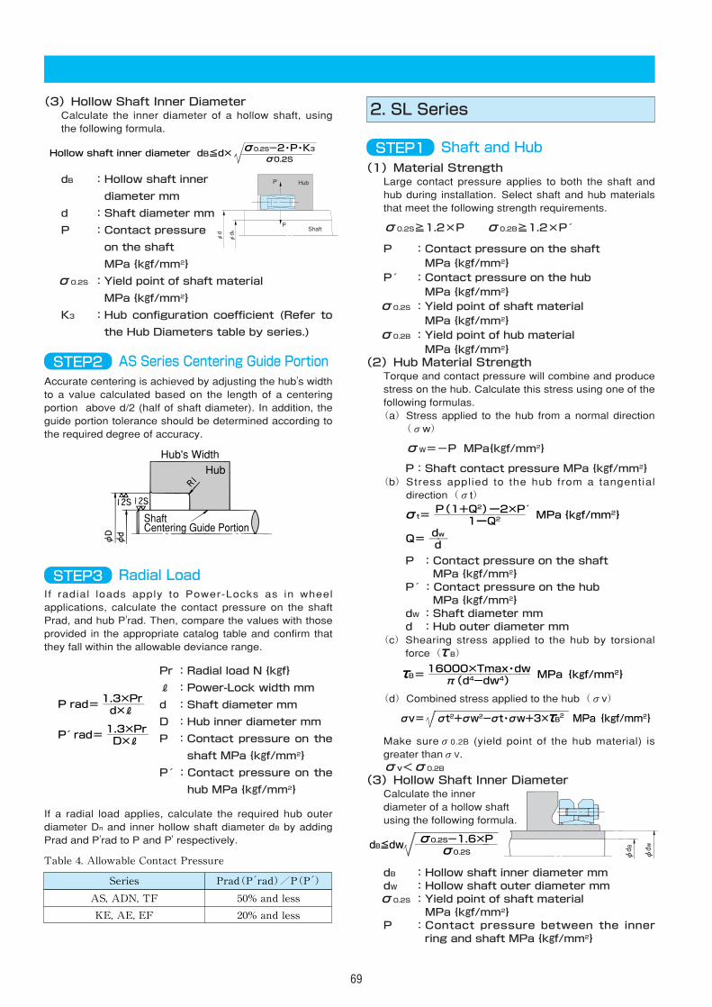
(1)Material StrengthLarge contact pressure applies to both the shaft andhub during installation. Select shaft and hub materialsthat meet the following strength requirements.
σ0.2S≧1.2×P σ0.2B≧1.2×P
P :Contact pressure on the shaftMPa{kgf/mm2}
P :Contact pressure on the hubMPa{kgf/mm2}
σ0.2S :Yield point of shaft materialMPa{kgf/mm2}
σ0.2B :Yield point of hub materialMPa{kgf/mm2}
(2)Hub Material StrengthTorque and contact pressure will combine and producestress on the hub. Calculate this stress using one of thefollowing formulas.(a)Stress applied to the hub from a normal direction
(σw)
σW=-P MPa{kgf/mm2}
P:Shaft contact pressure MPa{kgf/mm2}(b)Stress applied to the hub from a tangential
direction(σt)
P :Contact pressure on the shaftMPa{kgf/mm2}
P :Contact pressure on the hubMPa{kgf/mm2}
dW:Shaft diameter mmd :Hub outer diameter mm
(c)Shearing stress applied to the hub by torsionalforce(τB)
(d)Combined stress applied to the hub(σv)
Make sureσ0.2B (yield point of the hub material) isgreater thanσV.σv<σ0.2B
(3)Hollow Shaft Inner DiameterCalculate the innerdiameter of a hollow shaftusing the following formula.
dB :Hollow shaft inner diameter mmdW :Hollow shaft outer diameter mmσ0.2S :Yield point of shaft material
MPa{kgf/mm2}P :Contact pressure between the inner
ring and shaft MPa{kgf/mm2}
69
Table 4. Allowable Contact Pressure
Prad(P rad)/P(P )�
50% and less
Series
AS, ADN, TF
20% and lessKE, AE, EF
2. SL Series
STEP1 Shaft and Hub
Accurate centering is achieved by adjusting the hub's widthto a value calculated based on the length of a centeringportion above d/2 (half of shaft diameter). In addition, theguide portion tolerance should be determined according tothe required degree of accuracy.
STEP2 AS Series Centering Guide Portion
I f radial loads apply to Power-Locks as in wheelapplications, calculate the contact pressure on the shaftPrad, and hub P'rad. Then, compare the values with thoseprovided in the appropriate catalog table and confirm thatthey fall within the allowable deviance range.
Pr :Radial load N{kgf}
R :Power-Lock width mm
d :Shaft diameter mm
D :Hub inner diameter mm
P :Contact pressure on the
shaft MPa{kgf/mm2}
P :Contact pressure on the
hub MPa{kgf/mm2}
If a radial load applies, calculate the required hub outerdiameter Dn and inner hollow shaft diameter dB by addingPrad and P'rad to P and P' respectively.
STEP3 Radial Load
Hub's WidthHub
ShaftCentering Guide Portion
1.3×Pr�d×R
P rad= ――――�
1.3×Pr�D×R
P rad= ――――�
σt= ――――――――― MPa {kgf/mm2}�
dw�d
Q= ――�
P(1+Q2)ー2×P �1ーQ2
τB= ―――――――――― MPa {kgf/mm2}�16000×Tmax・dw�π(d4-dw4)�
σv= σt2+σw2-σt・σw+3×τB2 MPa {kgf/mm2}�
dB≦dw ――――――�σ0.2S-1.6×P�σ0.2S
(3)Hollow Shaft Inner DiameterCalculate the inner diameter of a hollow shaft, usingthe following formula.
dB :Hollow shaft inner
diameter mm
d :Shaft diameter mm
P :Contact pressure
on the shaft
MPa{kgf/mm2}
σ0.2S :Yield point of shaft material
MPa{kgf/mm2}
K3 :Hub configuration coefficient (Refer to
the Hub Diameters table by series.)
φdB
φd
P
P' Hub
Shaft
�
σ0.2S-2・P・K3�σ0.2S
Hollow shaft inner diameter dB≦d× ――――�
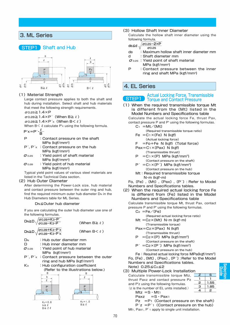
(3)Hollow Shaft Inner Diameter Calculate the hollow shaft inner diameter using thefollowing formula.
dB :Maximum hollow shaft inner diameter mmd :Shaft diameter mmσ0.2S :Yield point of shaft material
MPa{kgf/mm2}P :Contact pressure between the inner
ring and shaft MPa{kgf/mm2}
70
3. ML Series
STEP1 Shaft and Hub
(1)Material StrengthLarge contact pressure applies to both the shaft andhub during installation. Select shaft and hub materialsthat meet the following strength requirements.
σ0.2S≧1.4×Pσ0.2B≧1.4×P (When B≧R)σ0.2B≧1.4×P K(When B<R)When B<Rcalculate P'K using the following formula.
P :Contact pressure on the shaftMPa{kgf/mm2}
P , P K :Contact pressure on the hubMPa{kgf/mm2}
σ0.2S :Yield point of shaft materialMPa{kgf/mm2}
σ0.2B :Yield point of hub materialMPa{kgf/mm2}
Typical yield point values of various steel materials arelisted in the Technical Data section.
(2)Hub Outer DiameterAfter determining the Power-Lock size, hub materialand contact pressure between the outer ring and hub,find the required minimum outer hub diameter DN in theHub Diameters table for ML Series.
DN≦Outer hub diameter
If you are calculating the outer hub diameter use one ofthe following formulas.
(When B≧R)
(When B<R)
DN :Hub outer diameter mmD :Hub inner diameter mmσ0.2B :Yield point of hub material
MPa{kgf/mm2}P , P K :Contact pressure between the outer
ring and hub MPa{kgf/mm2}K3 :Hub configuration coefficient
(Refer to the illustrations below.)
B≧R B<R
DN≧D ――――――�σ0.2B+K3・P �σ0.2B-K3・P´�
DN≧D ―――――�σ0.2B+K3・P K�σ0.2B-K3・P K
dB≦d ―――――�σ0.2S-2×P�σ0.2S
4. EL Series
(1)When the required transmissible torque Mtis different from the〔Mt〕listed in theModel Numbers and Specifications table
Calculate the actual locking force Fe, thrust Pax,contact pressure P and P' using the following formulas.
C1 =Mt/〔Mt〕(Required transmissible torque ratio)
Fe =C1×〔Fe〕N{kgf}(Actual locking force)
F =Fo+Fe N{kgf}(Total force)Pax=C1×〔Pax〕N{kgf}
(Transmissible thrust)
P =C1×〔P〕MPa{kgf/mm2}(Contact pressure on the shaft)
P =C1×〔P 〕MPa{kgf/mm2}(Contact pressure on the hub)
Mt:Required transmissible torqueN・m{kgf・m}
Fo,〔Fe〕,〔Mt〕,〔Pax〕,〔P 〕: Refer to ModelNumbers and Specifications tables.
(2)When the required actual locking force Feis different from〔Fe〕listed in the ModelNumbers and Specifications table
Calculate transmissible torque Mt, thrust Pax, contactpressure P and P' using the following formulas.
C2 =Fe/〔Fe〕(Required actual locking force ratio)
Mt =C2×〔Mt〕N・m{kgf・m}(Transmissible torque)
Pax=C2×〔Pax〕N{kgf}(Transmissible thrust)
P =C2×〔P〕MPa{kgf/mm2}(Contact pressure on the shaft)
P =C2×〔P 〕MPa{kgf/mm2}(Contact pressure on the hub)
Fe:Required actual locking force MPa{kgf/mm2}Fo,〔Fe〕,〔Mt〕,〔Pax〕,〔P 〕:Refer to the ModelNumbers and Specifications tables.Note)0.25≦C2≦2
(3)Multiple Power-Lock InstallationCalculate transmissible torque Mtz,thrust Paxz and contact pressure Pzand P'z using the following formulas.(z is the number of EL units installed.)
Mtz =S・Mt1Paxz =S・Pax1Pz =P1(Contact pressure on the shaft)P z =P 1(Contact pressure on the hub)
Mt1, Pax1, P' 1 apply to single unit installation.
STEP1Actual Locking Force, TransmissibleTorque and Contact Pressure
P K=P・―�R�B
AS
AS
AS
AS
AS
AS
AS
AS
AS
EL
SelectionGuide
Z�1�2�3�4
S�1�1.55�1.85�2
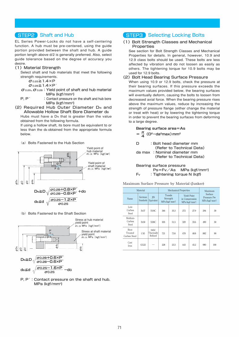
71
(1)Bolt Strength Classes and MechanicalProperties
See section for Bolt Strength Classes and MechanicalProperties for details. In general, however, 10.9 and12.9 class bolts should be used. These bolts are lessaffected by vibration and do not loosen as easily asothers. The tightening torque for 10.9 bolts may beused for 12.9 bolts.
(2)Bolt Head Bearing Surface PressureWhen using 10.9 or 12.9 bolts, check the pressure attheir bearing surfaces. If this pressure exceeds themaximum values provided below, the bearing surfaceswill eventually deform, causing the bolts to loosen fromdecreased axial force. When the bearing pressure risesabove the maximum values, reduce by increasing thestrength of pressure flange (either change the materialor treat with heat) or by lowering the tightening torquein order to prevent the bearing surfaces from deformingto a large degree.
D :Bolt head diameter mm(Refer to Technical Data)
da max :Nominal diameter mm(Refer to Technical Data)
Bearing surface pressurePs=Fv/As MPa{kgf/mm2}
FV :Tightening torque N{kgf}
STEP3 Selecting Locking Bolts
π�4
Bearing surface area=As�
= ― (D2-da2max)mm2
Maximum Surface Pressure by Material (Junker)
Material Mechanical Properties Maximum�Surface�
Pressure Pw�MPa{kgf/mm2}�
NameGerman�Standards
JIS�Equivalent
Tensile�Strength�
MPa{kgf/mm2}�
Yield Point�in Compression�MPa{kgf/mm2}�
Low-�Carbon�Steel
Medium-�Carbon�Steel
Heat�Treated�
Carbon Steel
St37�
St50�
C45�
GG22
S10C�
S30C�
�
―�
S45C�Thermally�Refined
346�
505�
721�
228
35.3�
51.5�
73.6�
23.3
272�
329�
478�
443
27.9�
33.6�
48.8�
45.2
294�
490�
882�
980
30�
50�
90�
100Cast�Iron
EL Series Power-Locks do not have a self-centeringfunction. A hub must be pre-centered, using the guideportion provided between the shaft and hub. A guideportion length above d/2 is generally preferred. Also, selectguide tolerance based on the degree of accuracy youdesire.(1)Material Strength
Select shaft and hub materials that meet the followingstrength requirements.σ0.2S≧1.4×Pσ0.2B≧1.4×P
σ0.2S、σ0.2B:Yield point of shaft and hub materialMPa{kgf/mm2}
P, P :Contact pressure on the shaft and hub boreMPa{kgf/mm2}
(2)Required Hub Outer Diameter DN andAllowable Hollow Shaft Bore Diameter dB
Hubs must have a DN that is greater than the valueobtained from the following formula.If using a hollow shaft, its bore must be equivalent to orless than the dB obtained from the appropriate formulabelow.
(a)Bolts Fastened to the Hub Section
(b)Bolts Fastened to the Shaft Section
P, P :Contact pressure on the shaft and hub. MPa{kgf/mm2}
STEP2 Shaft and Hub
Yield point ofhub material
Yield point ofshaft material
σ0.2B+0.8×P �σ0.2B-0.8×P �
DN≧D ―――――――― +dG
σ0.2S-1.2×P�σ0.2S
dB≦d ――――――――�
Stress at hub materialyield point
Stress at shaft materialyield point
σ0.2B+0.6×P �σ0.2B-0.6×P �
DN≧D ――――――――
σ0.2S-1.6×P�σ0.2S
dB≦d ―――――――― -dG
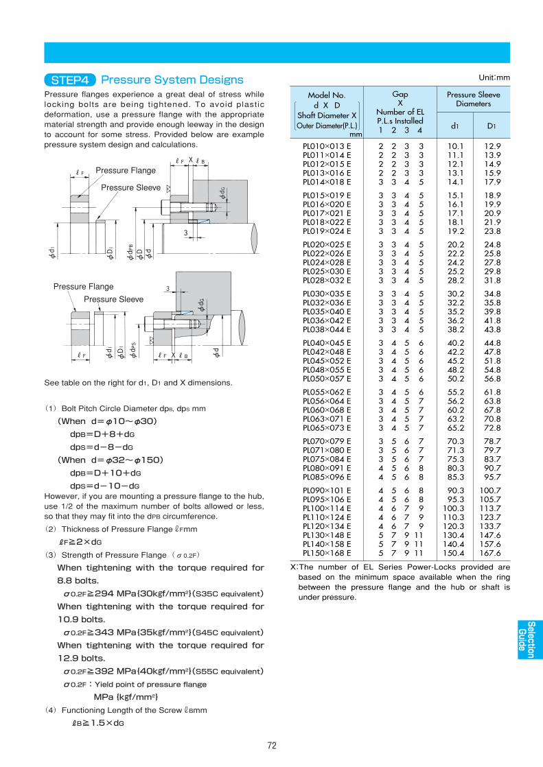
72
Pressure flanges experience a great deal of stress whilelocking bolts are being tightened. To avoid plasticdeformation, use a pressure flange with the appropriatematerial strength and provide enough leeway in the designto account for some stress. Provided below are examplepressure system design and calculations.
STEP4 Pressure System Designs
Pressure Flange
Pressure Sleeve
Pressure Flange
Pressure Sleeve
Unit:mm
Model No.d X D�
Shaft Diameter XOuter Diameter(P.L.)
Pressure SleeveDiameters
d1 D1
GapX
Number of ELP.L.s Installed
PL010×013 EPL011×014 EPL012×015 EPL013×016 EPL014×018 E
PL015×019 EPL016×020 EPL017×021 EPL018×022 EPL019×024 E
PL020×025 EPL022×026 EPL024×028 EPL025×030 EPL028×032 E
PL030×035 EPL032×036 EPL035×040 EPL036×042 EPL038×044 E
PL040×045 EPL042×048 EPL045×052 EPL048×055 EPL050×057 E
PL055×062 EPL056×064 EPL060×068 EPL063×071 EPL065×073 E
PL070×079 EPL071×080 EPL075×084 EPL080×091 EPL085×096 E
PL090×101 EPL095×106 EPL100×114 EPL110×124 EPL120×134 EPL130×148 EPL140×158 EPL150×168 E
22223
33333
33333
33333
33333
33333
33344
44444555
12.913.914.915.917.9
18.919.920.921.923.8
24.825.827.829.831.8
34.835.839.841.843.8
44.847.851.854.856.8
61.863.867.870.872.8
78.779.783.790.795.7
100.7105.7113.7123.7133.7147.6157.6167.6
10.111.112.113.114.1
15.116.117.118.119.2
20.222.224.225.228.2
30.232.235.236.238.2
40.242.245.248.250.2
55.256.260.263.265.2
70.371.375.380.385.3
90.395.3
100.3110.3120.3130.4140.4150.4
22223
33333
33333
33333
44444
44444
55555
55666777
33334
44444
44444
44444
55555
55555
66666
66777999
33335
55555
55555
55555
66666
67777
77788
88999
111111
1 2 3 4
X:The number of EL Series Power-Locks provided are based on the minimum space available when the ring between the pressure flange and the hub or shaft is under pressure.
mm
See table on the right for d1, D1 and X dimensions.
(1)Bolt Pitch Circle Diameter dpB, dpS mm
(When d=φ10~φ30)
dpB=D+8+dG
dpS=d-8-dG
(When d=φ32~φ150)
dpB=D+10+dG
dpS=d-10-dGHowever, if you are mounting a pressure flange to the hub,use 1/2 of the maximum number of bolts allowed or less,so that they may fit into the dPB circumference.
(2)Thickness of Pressure FlangerFmm
RF≧2×dG
(3)Strength of Pressure Flange(σ0.2F)
When tightening with the torque required for
8.8 bolts.
σ0.2F≧294 MPa{30kgf/mm2}(S35C equivalent)
When tightening with the torque required for
10.9 bolts.
σ0.2F≧343 MPa{35kgf/mm2}(S45C equivalent)
When tightening with the torque required for
12.9 bolts.
σ0.2F≧392 MPa{40kgf/mm2}(S55C equivalent)
σ0.2F:Yield point of pressure flange
MPa{kgf/mm2}
(4)Functioning Length of the ScrewrBmm
RB≧1.5×dG
AS
AS
AS
AS
AS
AS
AS
AS
AS
EL
SelectionGuide
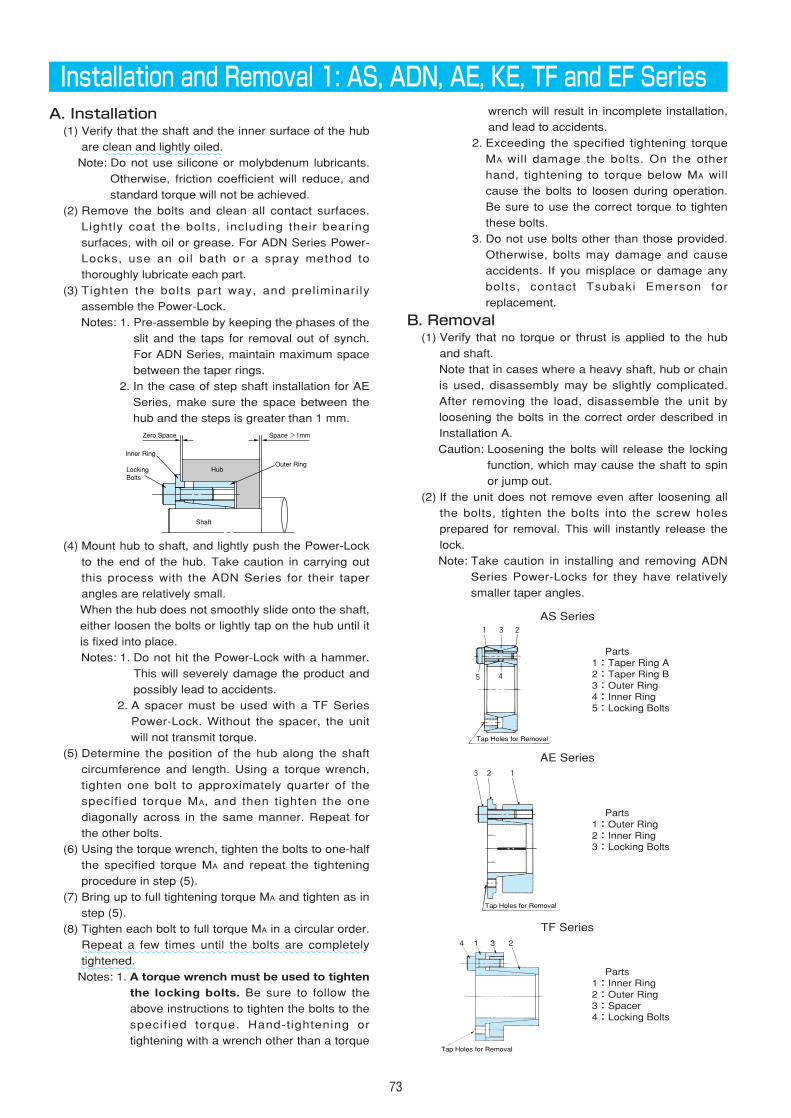
73
Installation and Removal 1: AS, ADN, AE, KE, TF and EF SeriesA. Installation
(1) Verify that the shaft and the inner surface of the hub
are clean and lightly oiled.
Note: Do not use silicone or molybdenum lubricants.
Otherwise, friction coefficient will reduce, and
standard torque will not be achieved.
(2) Remove the bolts and clean all contact surfaces.
Lightly coat the bolts, including their bearing
surfaces, with oil or grease. For ADN Series Power-
Locks, use an oil bath or a spray method to
thoroughly lubricate each part.
(3) Tighten the bolts part way, and preliminari ly
assemble the Power-Lock.
Notes: 1. Pre-assemble by keeping the phases of the
slit and the taps for removal out of synch.
For ADN Series, maintain maximum space
between the taper rings.
2. In the case of step shaft installation for AE
Series, make sure the space between the
hub and the steps is greater than 1 mm.
(4) Mount hub to shaft, and lightly push the Power-Lock
to the end of the hub. Take caution in carrying out
this process with the ADN Series for their taper
angles are relatively small.
When the hub does not smoothly slide onto the shaft,
either loosen the bolts or lightly tap on the hub until it
is fixed into place.
Notes: 1. Do not hit the Power-Lock with a hammer.
This will severely damage the product and
possibly lead to accidents.
2. A spacer must be used with a TF Series
Power-Lock. Without the spacer, the unit
will not transmit torque.
(5) Determine the position of the hub along the shaft
circumference and length. Using a torque wrench,
tighten one bolt to approximately quarter of the
specified torque MA, and then tighten the one
diagonally across in the same manner. Repeat for
the other bolts.
(6) Using the torque wrench, tighten the bolts to one-half
the specified torque MA and repeat the tightening
procedure in step (5).
(7) Bring up to full tightening torque MA and tighten as in
step (5).
(8) Tighten each bolt to full torque MA in a circular order.
Repeat a few times until the bolts are completely
tightened.
Notes: 1. A torque wrench must be used to tightenthe locking bolts. Be sure to follow the
above instructions to tighten the bolts to the
specif ied torque. Hand-tightening or
tightening with a wrench other than a torque
wrench will result in incomplete installation,
and lead to accidents.
2. Exceeding the specified tightening torque
MA will damage the bolts. On the other
hand, tightening to torque below MA will
cause the bolts to loosen during operation.
Be sure to use the correct torque to tighten
these bolts.
3. Do not use bolts other than those provided.
Otherwise, bolts may damage and cause
accidents. If you misplace or damage any
bolts, contact Tsubaki Emerson for
replacement.
B. Removal(1) Verify that no torque or thrust is applied to the hub
and shaft.
Note that in cases where a heavy shaft, hub or chain
is used, disassembly may be slightly complicated.
After removing the load, disassemble the unit by
loosening the bolts in the correct order described in
Installation A.
Caution: Loosening the bolts will release the locking
function, which may cause the shaft to spin
or jump out.
(2) If the unit does not remove even after loosening all
the bolts, tighten the bolts into the screw holes
prepared for removal. This will instantly release the
lock.
Note: Take caution in installing and removing ADN
Series Power-Locks for they have relatively
smaller taper angles.
Tap Holes for Removal
1�3�2�
5� 4�
3�2� 1�
Tap Holes for Removal
Parts1:Taper Ring A2:Taper Ring B3:Outer Ring4:Inner Ring5:Locking Bolts
AS Series
AE Series
Parts1:Outer Ring2:Inner Ring3:Locking Bolts
~~~~~~~~~~~~~~~~~~~~~
~~~~~~~~~~~~~~~~~~~~~~~~~~~~~~~~~~~~~~~~~~~~~~~~~~~~~~~~~~~~~
4 1 3 2
Tap Holes for Removal
Parts1:Inner Ring2:Outer Ring3:Spacer4:Locking Bolts
TF Series
Space >1mm
Outer RingHub
Shaft
Zero Space
Inner Ring
Locking�Bolts
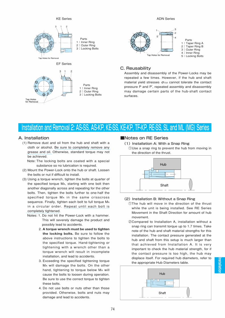
74
C. ReusabilityAssembly and disassembly of the Power-Locks may be
repeated a few times. However, if the hub and shaft
material yield stresses σ0.2 cannot tolerate the contact
pressure P and P', repeated assembly and disassembly
may damage certain parts of the hub-shaft contact
surfaces.
3 1 2
Tap Holes�for Removal
Parts1:Inner Ring2:Outer Ring3:Locking Bolts
EF Series
1
15
3
4
2�1
5
3
2
4
Tap Holes for Removal
Parts1:Taper Ring A2:Taper Ring B3:Outer Ring4:Inner Ring5:Locking Bolts
ADN Series
Installation and Removal 2: AS-SS, AS-KP, KE-SS, KE-KP, TF-KP, RE-SS, SL and ML (MG) SeriesA. Installation
(1) Remove dust and oil from the hub and shaft with a
cloth or alcohol. Be sure to completely remove any
grease and oil. Otherwise, standard torque may not
be achieved.
Note: The locking bolts are coated with a special
substance so no lubrication is required.
(2) Mount the Power-Lock onto the hub or shaft. Loosen
the bolts or nut if difficult to install.
(3) Using a torque wrench, tighten the bolts at quarter of
the specified torque MA, starting with one bolt then
another diagonally across and repeating for the other
bolts. Then, tighten the bolts further to one-half the
specif ied torque MA in the same crisscross
sequence. Finally, tighten each bolt to full torque MA
in a circular order. Repeat unti l each bolt is
completely tightened.
Notes: 1. Do not hit the Power-Lock with a hammer.
This will severely damage the product and
possibly lead to accidents.
2. A torque wrench must be used to tightenthe locking bolts. Be sure to follow the
above instructions to tighten the bolts to
the specified torque. Hand-tightening or
tightening with a wrench other than a
torque wrench will result in incomplete
installation, and lead to accidents.
3. Exceeding the specified tightening torque
MA will damage the bolts. On the other
hand, tightening to torque below MA will
cause the bolts to loosen during operation.
Be sure to use the correct torque to tighten
these bolts.
4. Do not use bolts or nuts other than those
provided. Otherwise, bolts and nuts may
damage and lead to accidents.
■Notes on RE Series(1)Installation A: With a Snap Ring①Use a snap ring to prevent the hub from moving in
the direction of the thrust.
(2)Installation B: Without a Snap Ring①The hub will move in the direction of the thrust
while the unit is being installed. See RE Series
Movement in the Shaft Direction for amount of hub
movement.
②Compared to Installation A, installation without a
snap ring can transmit torque up to 1.7 times. Take
note of the hub and shaft material strengths for this
installation. The contact pressure generated at the
hub and shaft from this setup is much larger than
that achieved from Installation A. It is very
important to check the hub material strength, for if
the contact pressure is too high, the hub may
displace itself. For required hub diameters, refer to
the appropriate Hub Diameters table.
Shaft
Hub
3 1 2
Tap Holes for Removal
Parts1:Inner Ring2:Outer Ring3:Locking Bolts
KE Series
AS
AS
AS
AS
AS
AS
AS
AS
AS
EL
Installation
Shaft
Hub
~~~~~~~~~~~~~~~~~~~~~~~~~~~~~~~~~~~~~~~~~~~~~~~~~~~
~~~~~~~~~~~~~~~~~~~~~~~~~~~~~~~~~~~~~~~~~~~~~~~~~~
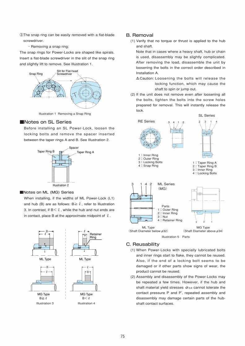
75
③The snap ring can be easily removed with a flat-blade
screwdriver.
・Removing a snap ring:
The snap rings for Power-Locks are shaped like spirals.
Insert a flat-blade screwdriver in the slit of the snap ring
and slightly lift to remove. See Illustration 1.
■Notes on SL SeriesBefore installing an SL Power-Lock, loosen the
locking bolts and remove the spacer inserted
between the taper rings A and B. See Illustration 2.
■Notes on ML (MG) Series
When installing, if the widths of ML Power-Lock (L1)
and hub (B) are as follows: B≧r, refer to Illustration
3. In contrast, if B<r, while the hub and nut ends are
in contact, place B at the approximate midpoint of r.
B. Removal(1) Verify that no torque or thrust is applied to the hub
and shaft.
Note that in cases where a heavy shaft, hub or chain
is used, disassembly may be slightly complicated.
After removing the load, disassemble the unit by
loosening the bolts in the correct order described in
Installation A.
Caution: Loosening the bolts will release the
locking function, which may cause the
shaft to spin or jump out.
(2) If the unit does not remove even after loosening all
the bolts, tighten the bolts into the screw holes
prepared for removal. This will instantly release the
lock.
C. Reusability(1) When Power-Locks with specially lubricated bolts
and inner rings start to flake, they cannot be reused.
Also, if the end of a locking bolt seems to be
damaged or if other parts show signs of wear, the
product cannot be reused.
(2) Assembly and disassembly of the Power-Locks may
be repeated a few times. However, if the hub and
shaft material yield stresses σ0.2 cannot tolerate the
contact pressure P and P', repeated assembly and
disassembly may damage certain parts of the hub-
shaft contact surfaces.
MG TypeB≧R
MG TypeB<R
ML Type ML Type
RetainerRing
Snap RingSlit for Flat-headScrewdriver
Illustration 1 Removing a Snap Ring
Illustration 3 Illustration 4
Illustration 2
Spacer
Taper Ring ATaper Ring B
13 4 2
3 2 1
13 4 2 12 3 4
1:Inner Ring2:Outer Ring3:Locking Bolts4:Snap Ring
1:Taper Ring A2:Taper Ring B3:Inner Ring4:Locking Bolts
Illustration 5 Parts
ML Type(Shaft Diameter belowφ32)
MG Type(Shaft Diameter aboveφ34)
SL Series
ML Series(MG)
Parts1:Outer Ring2:Inner Ring3:Nut4:Retainer Ring
RE Series
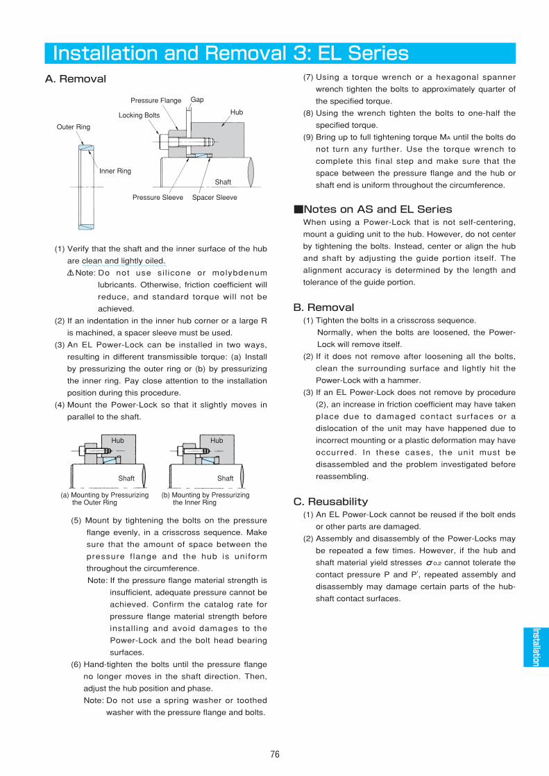
76
Installation and Removal 3: EL SeriesA. Removal
(1) Verify that the shaft and the inner surface of the hub
are clean and lightly oiled.
Note: Do not use sil icone or molybdenum
lubricants. Otherwise, friction coefficient will
reduce, and standard torque will not be
achieved.
(2) If an indentation in the inner hub corner or a large R
is machined, a spacer sleeve must be used.
(3) An EL Power-Lock can be installed in two ways,
resulting in different transmissible torque: (a) Install
by pressurizing the outer ring or (b) by pressurizing
the inner ring. Pay close attention to the installation
position during this procedure.
(4) Mount the Power-Lock so that it slightly moves in
parallel to the shaft.
(5) Mount by tightening the bolts on the pressure
flange evenly, in a crisscross sequence. Make
sure that the amount of space between the
pressure f lange and the hub is uniform
throughout the circumference.
Note: If the pressure flange material strength is
insufficient, adequate pressure cannot be
achieved. Confirm the catalog rate for
pressure flange material strength before
installing and avoid damages to the
Power-Lock and the bolt head bearing
surfaces.
(6) Hand-tighten the bolts until the pressure flange
no longer moves in the shaft direction. Then,
adjust the hub position and phase.
Note: Do not use a spring washer or toothed
washer with the pressure flange and bolts.
(7) Using a torque wrench or a hexagonal spanner
wrench tighten the bolts to approximately quarter of
the specified torque.
(8) Using the wrench tighten the bolts to one-half the
specified torque.
(9) Bring up to full tightening torque MA until the bolts do
not turn any further. Use the torque wrench to
complete this final step and make sure that the
space between the pressure flange and the hub or
shaft end is uniform throughout the circumference.
■Notes on AS and EL SeriesWhen using a Power-Lock that is not self-centering,
mount a guiding unit to the hub. However, do not center
by tightening the bolts. Instead, center or align the hub
and shaft by adjusting the guide portion itself. The
alignment accuracy is determined by the length and
tolerance of the guide portion.
B. Removal(1) Tighten the bolts in a crisscross sequence.
Normally, when the bolts are loosened, the Power-
Lock will remove itself.
(2) If it does not remove after loosening all the bolts,
clean the surrounding surface and lightly hit the
Power-Lock with a hammer.
(3) If an EL Power-Lock does not remove by procedure
(2), an increase in friction coefficient may have taken
place due to damaged contact surfaces or a
dislocation of the unit may have happened due to
incorrect mounting or a plastic deformation may have
occurred. In these cases, the unit must be
disassembled and the problem investigated before
reassembling.
C. Reusability(1) An EL Power-Lock cannot be reused if the bolt ends
or other parts are damaged.
(2) Assembly and disassembly of the Power-Locks may
be repeated a few times. However, if the hub and
shaft material yield stresses σ0.2 cannot tolerate the
contact pressure P and P', repeated assembly and
disassembly may damage certain parts of the hub-
shaft contact surfaces.
Outer Ring
Inner Ring
Locking Bolts
Pressure Sleeve Spacer Sleeve
Pressure Flange Gap
Hub
Shaft
Hub
Shaft
(a) Mounting by Pressurizing� the Outer Ring
(b) Mounting by Pressurizing� the Inner Ring
Shaft
Hub
AS
AS
AS
AS
AS
AS
AS
AS
AS
EL
Installation
~~~~~~~~~~~~~~~~~~~~~~
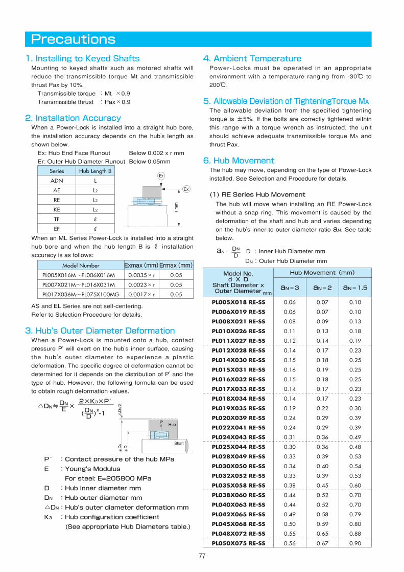
4. Ambient TemperaturePower-Locks must be operated in an appropriate
environment with a temperature ranging from -30℃ to
200℃.
5. Allowable Deviation of TighteningTorque MAThe allowable deviation from the specified tightening
torque is ±5%. If the bolts are correctly tightened within
this range with a torque wrench as instructed, the unit
should achieve adequate transmissible torque MA and
thrust Pax.
6. Hub MovementThe hub may move, depending on the type of Power-Lock
installed. See Selection and Procedure for details.
(1) RE Series Hub Movement
The hub will move when installing an RE Power-Lock
without a snap ring. This movement is caused by the
deformation of the shaft and hub and varies depending
on the hub's inner-to-outer diameter ratio aN. See table
below.
aN= D :Inner Hub Diameter mm
DN:Outer Hub Diameter mm
DN
D
77
1. Installing to Keyed ShaftsMounting to keyed shafts such as motored shafts will
reduce the transmissible torque Mt and transmissible
thrust Pax by 10%.
Transmissible torque :Mt ×0.9
Transmissible thrust :Pax×0.9
2. Installation AccuracyWhen a Power-Lock is installed into a straight hub bore,
the installation accuracy depends on the hub's length as
shown below.
Ex: Hub End Face Runout Below 0.002 x r mm
Er: Outer Hub Diameter Runout Below 0.05mm
When an ML Series Power-Lock is installed into a straight
hub bore and when the hub length B is r installation
accuracy is as follows:
AS and EL Series are not self-centering.
Refer to Selection Procedure for details.
3. Hub's Outer Diameter DeformationWhen a Power-Lock is mounted onto a hub, contact
pressure P' will exert on the hub's inner surface, causing
the hub 's outer diameter to experience a plastic
deformation. The specific degree of deformation cannot be
determined for it depends on the distribution of P' and the
type of hub. However, the following formula can be used
to obtain rough deformation values.
△DN≒ ×2×K3×P
( )2-1
P :Contact pressure of the hub MPa
E :Young's Modulus
For steel: E=205800 MPa
D :Hub inner diameter mm
DN :Hub outer diameter mm
△DN:Hub's outer diameter deformation mm
K3 :Hub configuration coefficient
(See appropriate Hub Diameters table.)
DND
DNE
Precautions
Series
ADN
AE
RE
KE
TF
EF
Hub Length B
L
L2
L2
L2
R
R
Model Number
PL005X016M~PL006X016MG
PL007X021M~PL016X031MG
PL017X036M~PL075X100MG
Exmax(mm)
0.0035×r
0.0023×r
0.0017×r
Ermax(mm)
0.05
0.05
0.05
Model No.d X D
Shaft Diameter xOuter Diametermm
aN=3 aN=2 aN=1.5
PL005X018 RE-SS
PL006X019 RE-SS
PL008X021 RE-SS
PL010X026 RE-SS
PL011X027 RE-SS
PL012X028 RE-SS
PL014X030 RE-SS
PL015X031 RE-SS
PL016X032 RE-SS
PL017X033 RE-SS
PL018X034 RE-SS
PL019X035 RE-SS
PL020X039 RE-SS
PL022X041 RE-SS
PL024X043 RE-SS
PL025X044 RE-SS
PL028X049 RE-SS
PL030X050 RE-SS
PL032X052 RE-SS
PL035X058 RE-SS
PL038X060 RE-SS
PL040X063 RE-SS
PL042X065 RE-SS
PL045X068 RE-SS
PL048X072 RE-SS
PL050X075 RE-SS
0.06
0.06
0.08
0.11
0.12
0.14
0.15
0.16
0.15
0.14
0.14
0.19
0.24
0.24
0.31
0.30
0.33
0.34
0.33
0.38
0.44
0.44
0.49
0.50
0.55
0.56
0.07
0.07
0.09
0.13
0.14
0.17
0.18
0.19
0.18
0.17
0.17
0.22
0.29
0.29
0.36
0.36
0.39
0.40
0.39
0.45
0.52
0.52
0.58
0.59
0.65
0.67
0.10
0.10
0.13
0.18
0.19
0.23
0.25
0.25
0.25
0.23
0.23
0.30
0.39
0.39
0.49
0.48
0.53
0.54
0.53
0.60
0.70
0.70
0.79
0.80
0.88
0.90
Hub Movement(mm)
Er
Ex
r mm
△DN/2
φDN
φD
P' Hub
Shaft
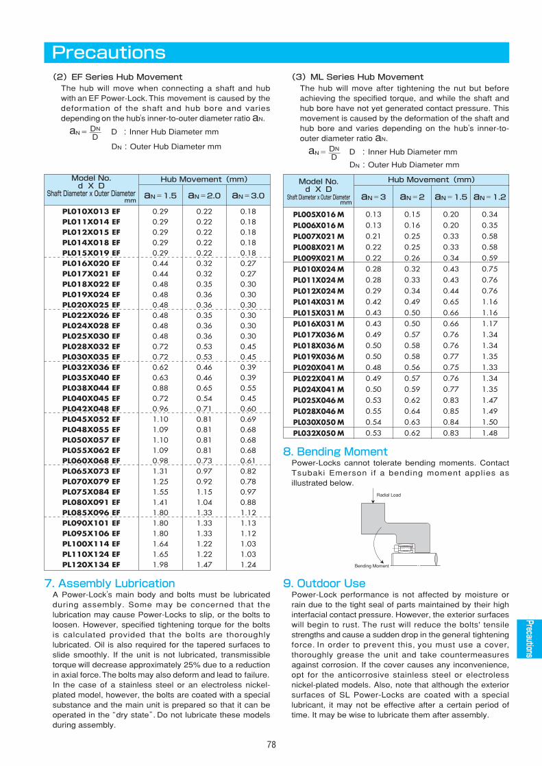
Model No.d X D
Shaft Diameter x Outer Diameter aN=2aN=3 aN=1.5 aN=1.2
PL005X016 MPL006X016 MPL007X021 MPL008X021 MPL009X021 MPL010X024 MPL011X024 MPL012X024 MPL014X031 MPL015X031 MPL016X031 MPL017X036 MPL018X036 MPL019X036 MPL020X041 MPL022X041 MPL024X041 MPL025X046 MPL028X046 MPL030X050 MPL032X050 M
0.130.130.210.220.220.280.280.290.420.430.430.490.500.500.480.490.500.530.550.540.53
0.150.160.250.250.260.320.330.340.490.500.500.570.580.580.560.570.590.620.640.630.62
0.200.200.330.330.340.430.430.440.650.660.660.760.760.770.750.760.770.830.850.840.83
0.340.350.580.580.590.750.760.761.161.161.171.341.341.351.331.341.351.471.491.501.48
Hub Movement(mm)
78
(2)EF Series Hub MovementThe hub will move when connecting a shaft and hubwith an EF Power-Lock. This movement is caused by thedeformation of the shaft and hub bore and variesdepending on the hub's inner-to-outer diameter ratio aN.
aN= D :Inner Hub Diameter mm
DN:Outer Hub Diameter mm
DN
D
(3)ML Series Hub MovementThe hub will move after tightening the nut but beforeachieving the specified torque, and while the shaft andhub bore have not yet generated contact pressure. Thismovement is caused by the deformation of the shaft andhub bore and varies depending on the hub's inner-to-outer diameter ratio aN.
aN= D :Inner Hub Diameter mm
DN:Outer Hub Diameter mm
DN
D
9. Outdoor UsePower-Lock performance is not affected by moisture orrain due to the tight seal of parts maintained by their highinterfacial contact pressure. However, the exterior surfaceswill begin to rust. The rust will reduce the bolts' tensilestrengths and cause a sudden drop in the general tighteningforce. In order to prevent this, you must use a cover,thoroughly grease the unit and take countermeasuresagainst corrosion. If the cover causes any inconvenience,opt for the anticorrosive stainless steel or electrolessnickel-plated models. Also, note that although the exteriorsurfaces of SL Power-Locks are coated with a speciallubricant, it may not be effective after a certain period oftime. It may be wise to lubricate them after assembly.
8. Bending MomentPower-Locks cannot tolerate bending moments. ContactTsubaki Emerson if a bending moment applies asillustrated below.
Precautions
Model No.d X D
Shaft Diameter x Outer Diametermm aN=1.5 aN=2.0 aN=3.0
PL010X013 EFPL011X014 EF PL012X015 EF PL014X018 EFPL015X019 EF PL016X020 EFPL017X021 EFPL018X022 EFPL019X024 EFPL020X025 EFPL022X026 EFPL024X028 EFPL025X030 EFPL028X032 EFPL030X035 EFPL032X036 EFPL035X040 EFPL038X044 EFPL040X045 EFPL042X048 EFPL045X052 EFPL048X055 EF PL050X057 EF PL055X062 EFPL060X068 EF PL065X073 EFPL070X079 EFPL075X084 EFPL080X091 EFPL085X096 EFPL090X101 EFPL095X106 EFPL100X114 EFPL110X124 EFPL120X134 EF
0.290.290.290.290.290.440.440.480.480.480.480.480.480.720.720.620.630.880.720.961.101.091.101.090.981.311.251.551.411.801.801.801.641.651.98
0.220.220.220.220.220.320.320.350.360.360.350.360.360.530.530.460.460.650.540.710.810.810.810.810.730.970.921.151.041.331.331.331.221.221.47
0.180.180.180.180.180.270.270.300.300.300.300.300.300.450.450.390.390.550.450.600.690.680.680.680.610.820.780.970.881.121.131.121.031.031.24
Hub Movement(mm)AS
AS
AS
AS
AS
AS
AS
AS
AS
EL
Precautions
mm
Radial Load
Bending Moment
7. Assembly LubricationA Power-Lock's main body and bolts must be lubricatedduring assembly. Some may be concerned that thelubrication may cause Power-Locks to slip, or the bolts toloosen. However, specified tightening torque for the boltsis calculated provided that the bolts are thoroughlylubricated. Oil is also required for the tapered surfaces toslide smoothly. If the unit is not lubricated, transmissibletorque will decrease approximately 25% due to a reductionin axial force.The bolts may also deform and lead to failure. In the case of a stainless steel or an electroless nickel-plated model, however, the bolts are coated with a specialsubstance and the main unit is prepared so that it can beoperated in the“dry state”. Do not lubricate these modelsduring assembly.
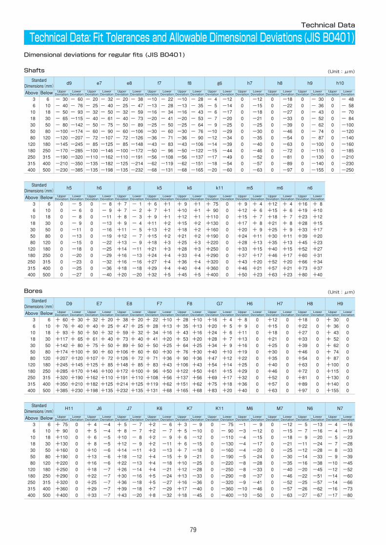
79
Technical Data
Technical Data: Fit Tolerances and Allowable Dimensional Deviations (JIS B0401)Dimensional deviations for regular fits (JIS B0401)
Shafts
StandardDimensions(mm)
d9 e7 e8 f7 f8 g6 h7 h8 h9 h10
Above Below UpperDeviation
LowerDeviation
UpperDeviation
LowerDeviation
UpperDeviation
LowerDeviation
UpperDeviation
LowerDeviation
UpperDeviation
LowerDeviation
UpperDeviation
LowerDeviation
UpperDeviation
LowerDeviation
UpperDeviation
LowerDeviation
UpperDeviation
LowerDeviation
UpperDeviation
LowerDeviation
003 06 -030 -060 -020 -032 -020 -038 -10 -022 -10 -028 -04 -12 0 -12 0 -18 0 -030 0 -048006 010 -040 -076 -025 -040 -025 -047 -13 -028 -13 -035 -05 -14 0 -15 0 -22 0 -036 0 -058010 018 -050 -093 -032 -050 -032 -059 -16 -034 -16 -043 -06 -17 0 -18 0 -27 0 -043 0 -070018 030 -065 -115 -040 -061 -040 -073 -20 -041 -20 -053 -07 -20 0 -21 0 -33 0 -052 0 -084030 050 -080 -142 -050 -075 -050 -089 -25 -050 -25 -064 -09 -25 0 -25 0 -39 0 -062 0 -100050 080 -100 -174 -060 -090 -060 -106 -30 -060 -30 -076 -10 -29 0 -30 0 -46 0 -074 0 -120080 120 -120 -207 -072 -107 -072 -126 -36 -071 -36 -090 -12 -34 0 -35 0 -54 0 -087 0 -140120 180 -145 -245 -085 -125 -085 -148 -43 -083 -43 -106 -14 -39 0 -40 0 -63 0 -100 0 -160180 250 -170 -285 -100 -146 -100 -172 -50 -096 -50 -122 -15 -44 0 -46 0 -72 0 -115 0 -185250 315 -190 -320 -110 -162 -110 -191 -56 -108 -56 -137 -17 -49 0 -52 0 -81 0 -130 0 -210315 400 -210 -350 -135 -182 -125 -214 -62 -119 -62 -151 -18 -54 0 -57 0 -89 0 -140 0 -230400 500 -230 -385 -135 -198 -135 -232 -68 -131 -68 -165 -20 -60 0 -63 0 -97 0 -155 0 -250
StandardDimensions(mm)
D9 E7 E8 F7 F8 G7 H6 H7 H8 H9
Above Below UpperDeviation
LowerDeviation
UpperDeviation
LowerDeviation
UpperDeviation
LowerDeviation
UpperDeviation
LowerDeviation
UpperDeviation
LowerDeviation
UpperDeviation
LowerDeviation
UpperDeviation
LowerDeviation
UpperDeviation
LowerDeviation
UpperDeviation
LowerDeviation
UpperDeviation
LowerDeviation
003 006 +060 +030 +032 +020 +038 +020 +022 +10 +028 +10 +16 +04 +08 0 +12 0 +18 0 +030 0006 010 +076 +040 +040 +025 +047 +025 +028 +13 +035 +13 +20 +05 +09 0 +15 0 +22 0 +036 0010 018 +093 +050 +050 +032 +059 +032 +034 +16 +043 +16 +24 +06 +11 0 +18 0 +27 0 +043 0018 030 +117 +065 +061 +040 +073 +040 +041 +20 +053 +20 +28 +07 +13 0 +21 0 +33 0 +052 0030 050 +142 +080 +075 +050 +089 +050 +050 +25 +064 +25 +34 +09 +16 0 +25 0 +39 0 +062 0050 080 +174 +100 +090 +060 +106 +060 +060 +30 +076 +30 +40 +10 +19 0 +30 0 +46 0 +074 0080 120 +207 +120 +107 +072 +126 +072 +071 +36 +090 +36 +47 +12 +22 0 +35 0 +54 0 +087 0120 180 +245 +145 +125 +085 +148 +085 +083 +43 +106 +43 +54 +14 +25 0 +40 0 +63 0 +100 0180 250 +285 +170 +146 +100 +172 +100 +096 +50 +122 +50 +61 +15 +29 0 +46 0 +72 0 +115 0250 315 +320 +190 +162 +110 +191 +110 +108 +56 +137 +56 +69 +17 +32 0 +52 0 +81 0 +130 0315 400 +350 +210 +182 +125 +214 +125 +119 +62 +151 +62 +75 +18 +36 0 +57 0 +89 0 +140 0400 500 +385 +230 +198 +135 +232 +135 +131 +68 +165 +68 +83 +20 +40 0 +63 0 +97 0 +155 0
StandardDimensions(mm)
H11 J6 J7 K6 K7 K11 M6 M7 N6 N7
Above Below UpperDeviation
LowerDeviation
UpperDeviation
LowerDeviation
UpperDeviation
LowerDeviation
UpperDeviation
LowerDeviation
UpperDeviation
LowerDeviation
UpperDeviation
LowerDeviation
UpperDeviation
LowerDeviation
UpperDeviation
LowerDeviation
UpperDeviation
LowerDeviation
UpperDeviation
LowerDeviation
003 006 +075 0 +04 -4 +05 -07 +2 -06 +03 -09 0 -075 -1 -09 0 -12 -05 -13 -04 -16006 010 +090 0 +05 -4 +08 -07 +2 -07 +05 -10 0 -090 -3 -12 0 -15 -07 -16 -04 -19010 018 +110 0 +06 -5 +10 -08 +2 -09 +06 -12 0 -110 -4 -15 0 -18 -09 -20 -05 -23018 030 +130 0 +08 -5 +12 -09 +2 -11 +06 -15 0 -130 -4 -17 0 -21 -11 -24 -07 -28030 050 +160 0 +10 -6 +14 -11 +3 -13 +07 -18 0 -160 -4 -20 0 -25 -12 -28 -08 -33050 080 +190 0 +13 -6 +18 -12 +4 -15 +09 -21 0 -190 -5 -24 0 -30 -14 -33 -09 -39080 120 +220 0 +16 -6 +22 -13 +4 -18 +10 -25 0 -220 -8 -28 0 -35 -16 -38 -10 -45120 180 +250 0 +18 -7 +26 -14 +4 -21 +12 -28 0 -250 -8 -33 0 -40 -20 -45 -12 -52180 250 +290 0 +22 -7 +30 -16 +5 -24 +13 -33 0 -290 -8 -37 0 -46 -22 -51 -14 -60250 315 +320 0 +25 -7 +36 -18 +5 -27 +16 -36 0 -320 -9 -41 0 -52 -25 -57 -14 -66315 400 +360 0 +29 -7 +39 -18 +7 -29 +17 -40 0 -360 -10 -46 0 -57 -26 -62 -16 -73400 500 +400 0 +33 -7 +43 -20 +8 -32 +18 -45 0 -400 -10 -50 0 -63 -27 -67 -17 -80
StandardDimensions(mm)
h5 h6 j6 k5 k6 k11 m5 m6 n6
Above Below UpperDeviation
LowerDeviation
UpperDeviation
LowerDeviation
UpperDeviation
LowerDeviation
UpperDeviation
LowerDeviation
UpperDeviation
LowerDeviation
UpperDeviation
LowerDeviation
UpperDeviation
LowerDeviation
UpperDeviation
LowerDeviation
UpperDeviation
LowerDeviation
003 006 0 -05 0 -08 +07 -01 +06 +1 +09 +1 +075 0 +09 +04 +12 +04 +16 +08006 010 0 -06 0 -09 +07 -02 +07 +1 +10 +1 +090 0 +12 +06 +15 +06 +19 +10010 018 0 -08 0 -11 +08 -03 +09 +1 +12 +1 +110 0 +15 +07 +18 +07 +23 +12018 030 0 -09 0 -13 +09 -04 +11 +2 +15 +2 +130 0 +17 +08 +21 +08 +28 +15030 050 0 -11 0 -16 +11 -05 +13 +2 +18 +2 +160 0 +20 +09 +25 +09 +33 +17050 080 0 -13 0 -19 +12 -07 +15 +2 +21 +2 +190 0 +24 +11 +30 +11 +39 +20080 120 0 -15 0 -22 +13 -09 +18 +3 +25 +3 +220 0 +28 +13 +35 +13 +45 +23120 180 0 -18 0 -25 +14 -11 +21 +3 +28 +3 +250 0 +33 +15 +40 +15 +52 +27180 250 0 -20 0 -29 +16 -13 +24 +4 +33 +4 +290 0 +37 +17 +46 +17 +60 +31250 315 0 -23 0 -32 +16 -16 +27 +4 +36 +4 +320 0 +43 +20 +52 +20 +66 +34315 400 0 -25 0 -36 +18 -18 +29 +4 +40 +4 +360 0 +46 +21 +57 +21 +73 +37400 500 0 -27 0 -40 +20 -20 +32 +5 +45 +5 +400 0 +50 +23 +63 +23 +80 +40
(Unit:μm)
Bores (Unit:μm)

80
NameJIS
StandardNo.
Steel ProductsNo.
Standard Quenching, TemperingYield Pointσ0.2
Tensile StrengthσB
Yield Pointσ0.2
Tensile StrengthσB
MPa kgf/mm2 MPa kgf/mm2 MPa kgf/mm2 MPa kgf/mm2
Rolled Steel for GeneralStructural Use
G3101SS330 177 18 333~431 34~44SS400 216 22 402~510 41~52SS490 255 26 490~607 50~62
Carbon Steel forMachine Structural Use
G4051
S15C 235 24 373 38S25C 265 27 441 45S30C 284 29 471 48 333 34 0539 055S35C 304 31 510 52 392 40 0568 058S40C 324 33 539 55 441 45 0607 062S45C 343 35 569 58 490 50 0686 070S50C 363 37 608 62 539 55 0735 075S55C 392 40 647 66 588 60 0784 080
Nickel-chromium Steel G4102SNC236 588 60 0735 075SNC631 735 75 0833 085SNC836 784 80 0882 090
Nickel-chromium- molybdenumSteel
G4103
SNCM240 784 80 0882 090SNCM431 686 70 0833 085SNCM439 882 90 0980 100SNCM447 931 95 1030 105SNCM625 833 85 0931 095SNCM630 882 90 1079 110
Chromium- molybdenum Steel G4105
SCM430 686 70 0833 085SCM432 735 75 0882 090SCM435 784 80 0931 095SCM440 833 85 0980 100SCM445 882 90 1030 105
Manganese Steel forMachine Structural Use
andManganese-chromium Steel
G4106SMn433 539 55 0686 070SMn438 588 60 0735 075SMn443 637 65 0784 080
SMnC443 784 80 0931 095
Chrome Steel G4104SCr420 637 65 0784 080SCr435 735 75 0882 090SCr440 784 80 0931 095SCr445 833 85 0980 100
Stainless Steel G4303
SUS301 206 21 520 53SUS302 206 21 520 53SUS303 206 21 520 53SUS304 206 21 520 53SUS308 206 21 520 53SUS316 206 21 520 53SUS317 206 21 520 53SUS347 206 21 520 53SUS405 177 18 412 42SUS429 206 21 451 46SUS430 206 21 451 46SUS434 206 21 451 46SUS403 392 40 0588 060SUS410 343 35 0539 055SUS416 343 35 0539 055SUS431 586 60 0785 080
}Note2
}Note3
}Note4
}Note1
}Note5
}Note6
Technical Data
Technical Data: Iron and Steel Material Strengths
Technical Data: Cast and Wrought Product Material Strengths
NameJIS
StandardNo.
Steel ProductsNo.
Standard Quenching, TemperingYield Pointσ0.2
Tensile StrengthσB
Yield Pointσ0.2
Tensile StrengthσB
MPa kgf/mm2 MPa kgf/mm2 MPa kgf/mm2 MPa kgf/mm2
Carbon Steel Forgings forGeneral Use
G3201
SF340A 176 18 343~441 35~45SF390A 196 20 392~490 40~50SF440A 226 23 441~539 45~55SF490A 245 25 490~588 50~60SF540A 275 28 539~637 55~65SF590A 294 30 588~686 60~70SF540B 294 30 539~686 55~70SF590B 324 33 588~736 65~75SF640B 343 35 637~785 65~80
Carbon Steel Castings G5101SC360 177 18 363 37SC410 205 21 412 42SC450 225 23 451 46SC480 245 25 481 49
Gray Iron Castings G5502FC200 117 12 167 17FC250 147 15 216 22FC300 186 19 265 27FC350 215 22 314 32
Spheroidal Graphite IronCastings
G5502
FCD400 255 26 392 40FCD450 284 29 441 45FCD500 324 33 490 50FCD600 373 38 588 60FCD700 422 43 686 70
Black Heart Malleable IronCastings
G5702FCMB210 167 17 275 28FCMB310 186 19 314 32FCMB340 206 21 343 35FCMB360 216 22 363 37
}Note1
}Note2
Note 1) Normalized Note 2) Austenite Stainless Steel Note 3) Ferrite Stainless SteelNote 4) Martensite Stainless Steel Note 5) Solution Treated Note 6) Annealed
Note 1) Annealed, normalized or normalized and tempered. Note 2) Cast iron products do not have a yield point. For the purpose of designing convenience, use the 70% value of each product's tensile
strength to calculate the required hub outer diameter.
AS
AS
AS
AS
AS
AS
AS
AS
AS
EL
TechnicalData
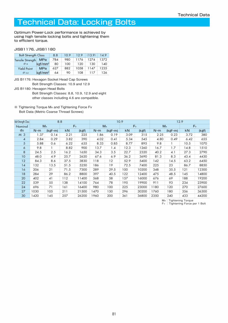
81
Technical Data
Technical Data: Locking BoltsOptimum Power-Lock performance is achieved byusing high tensile locking bolts and tightening themto efficient torque.
Bolt Strength Class 8.8 10.9 12.9 (13.9) 14.9
Tensile StrengthσB
MPa 784 980 1176 1274 1372
kgf/mm2 080 100 0120 0130 0140
Yield Pointσ0.2
MPa 627 882 1058 1147 1235
kgf/mm2 064 090 0108 0117 0126
JISB1176, JISB1180
JIS B1176: Hexagon Socket Head Cap Screws
Bolt Strength Classes: 10.9 and 12.9
JIS B1180: Hexagon Head Bolts
Bolt Strength Classes: 8.8, 10.9, 12.9 and eight
other classes including 4.6 are compatible.
※ Tightening Torque MA and Tightening Force Fv
Bolt Data (Metric Coarse Thread Screws)
Bolt Strength Class 8.8 10.9 12.9
NominaldG
MA FV MA FV MA FVN・m {kgf・m} kN {kgf} N・m {kgf・m} kN {kgf} N・m {kgf・m} kN {kgf}
M03 0001.37 000.14 002.21 00225 0001.86 000.19 003.09 00315 0002.25 000.23 003.72 00380M04 0002.84 000.29 003.82 00390 0004.02 000.41 005.34 00545 0004.80 000.49 006.42 00655M05 0005.88 000.60 006.22 00635 0008.33 000.85 008.77 00895 0009.80 001.00 010.50 01070M06 0009.80 001.00 008.82 00900 0013.70 001.40 012.30 01260 0016.70 001.70 014.80 01510M08 0024.50 002.50 016.20 01650 0034.30 003.50 022.70 02320 0040.20 004.10 027.30 02790M10 0048.00 004.90 025.70 02620 0067.60 006.90 036.20 03690 0081.30 008.30 043.40 04430M12 0084.30 008.60 037.50 03830 0118.00 012.00 052.90 05400 0142.00 014.50 063.20 06450M14 0132.00 013.50 051.50 05250 0186.00 019.00 072.50 07400 0225.00 023.00 086.70 08850M16 0206.00 021.00 071.50 07300 0289.00 029.50 100.00 10200 0348.00 035.50 121.00 12300M18 0284.00 029.00 086.20 08800 0397.00 040.50 122.00 12400 0475.00 048.50 145.00 14800M20 0402.00 041.00 112.00 11400 0568.00 058.00 157.00 16000 0676.00 069.00 188.00 19200M22 0539.00 055.00 138.00 14100 0764.00 078.00 195.00 19900 0911.00 093.00 234.00 23900M24 0696.00 071.00 161.00 16400 0980.00 100.00 225.00 23000 1180.00 120.00 270.00 27600M27 1030.00 105.00 211.00 21500 1470.00 150.00 296.00 30200 1760.00 180.00 356.00 36300M30 1420.00 145.00 257.00 26200 1960.00 200.00 361.00 36800 2350.00 240.00 433.00 44200
MA:Tightening TorqueFV :Tightening Force per 1 Bolt
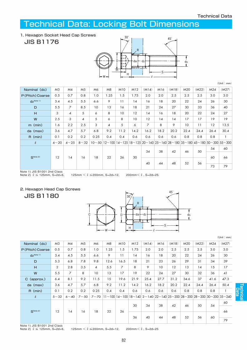
82
Technical Data
Technical Data: Locking Bolt Dimensions1. Hexagon Socket Head Cap Screws
JIS B1176
2. Hexagon Head Cap Screws
JIS B1180
Nominal(dG) M3 M4 M5 M6 M8 M10 M12 (M14) M16 (M18) M20 (M22) M24 (M27)
P(Pitch)Coarse 0.5 0.7 0.8 1.0 1.25 1.5 1.75 2.0 2.0 2.5 2.5 2.5 3.0 3.0
d2Note 1) 3.4 4.5 5.5 6.6 9 11 14 16 18 20 22 24 26 30
D 5.5 7 8.5 10 13 16 18 21 24 27 30 33 36 40
H 3 4 5 6 8 10 12 14 16 18 20 22 24 27
W 2.5 3 4 5 6 8 10 12 14 14 17 17 19 19
m(min) 1.6 2.2 2.5 3 4 5 6 7 8 9 10 11 12 13.5
da(max) 3.6 4.7 5.7 6.8 9.2 11.2 14.2 16.2 18.2 20.2 22.4 24.4 26.4 30.4
R(min) 0.1 0.2 0.2 0.25 0.4 0.4 0.6 0.6 0.6 0.6 0.8 0.8 0.8 1
R 4~20 4~25 8~32 10~50 12~100 14~125 18~125 20~160 25~160 28~180 35~180 45~180 50~300 55~300
SNote 2) 12 14 16 18 22 26 30
34 38 42 46 5054 60
66
44 48 52 5679
40
Nominal(dG) M3 M4 M5 M6 M8 M10 M12 (M14) M16 (M18) M20 (M22) M24 (M27)
P(Pitch)Coarse 0.5 0.7 0.8 1.0 1.25 1.5 1.75 2.0 2.0 2.5 2.5 2.5 3.0 3.0
d2Note 1) 3.4 4.5 5.5 6.6 9 11 14 16 18 20 22 24 26 30
D 5.3 6.8 7.8 9.8 12.6 16.5 18 21 23 26 29 31 34 39
H 2 2.8 3.5 4 5.5 7 8 9 10 12 13 14 15 17
W 5.5 7 8 10 13 17 19 22 24 27 30 32 36 41
C(approx.) 6.4 8.1 9.2 11.5 15 19.6 21.9 25.4 27.7 31.2 34.6 37 41.6 47.3
da(max) 3.6 4.7 5.7 6.8 9.2 11.2 14.2 16.2 18.2 20.2 22.4 24.4 26.4 50.4
R(min) 0.1 0.2 0.2 0.25 0.4 0.4 0.6 0.6 0.6 0.6 0.8 0.8 0.8 1
R 5~32 6~40 7~50 7~70 11~100 14~100 18~140 2~140 22~140 25~200 28~200 28~200 30~200 35~240
SNote 2) 12 14 16 18 22 26
30 34 38 42 46 50 5460
66
36 40 44 48 52 56 6079
60
Note 1) JIS B1001 2nd ClassNote 2) r≦ 125mm, S=2d+6, 125mm <r≦200mm, S=2d+12, 200mm<r, S=2d+25
Note 1) JIS B1001 2nd ClassNote 2) r≦ 125mm, S=2d+6, 125mm <r≦200mm, S=2d+12, 200mm<r, S=2d+25
(Unit:mm)
(Unit:mm)
73
AS
AS
AS
AS
AS
AS
AS
AS
AS
EL
TechnicalData

83
MEMO

84
MEMO

85
MEMO

●Be sure to use a torque wrench to tighten each bolt to its specified torque.
●Do not use bolts other than those provided. If you misplace the bolts, contact your distributor or Tsubaki Emersonfor replacement.
●Observe the Labor Safety and Hygiene Regulations, General Criteria, Paragraph 1, Chapter 1, Edition 2.
●Observe the following when installing, removing, maintaining or inspecting the product.・Dress appropriately and wear safety glasses, gloves and shoes where necessary.・Turn off the power and make sure it does not reconnect accidentally.・Operate according to the instructions provided in the manual or catalog (where appropriate).
●To inspect a Power-Lock, you must either remove the load, including any suspended equipment, or implement aprotective measure against the disconnection of hub and shaft. Removing the product without care may result inaccidents.
●Do not use a torque wrench without an adjusting scale because the bolts may not tighten to the specified torqueand may cause accidents. Do not attach a pipe to the torque wrench lever. Doing so will affect the accuracy ofthe wrench.
●Install a safety device to your equipment, if the bolts have been loosened, or if danger is suspected due toinstallation, operation or environment conditions. Periodic inspection of the bolts for tightness is recommended.
●The instruction manual must be delivered to the final user.
Observe the following safety precautions to prevent serious injuries.
Observe the following safety precautions to prevent accidents.
WARNING
CAUTION
SAFETY INFORMATION
CautionThe information contained herein is intended merely to assist you through the productselection process. Read the actual instruction manual before you operate the product.
1. Warranty period without charge
18 months effective the date of shipment or 12 months effective the
first use of Goods, including installation of Goods to Buyer's
equipment or machines - whichever comes first.
2. Warranty coverage
Should any damage or problem with the Goods arise within the
warranty period, given that the Goods were operated and
maintained according to the instructions provided in the manual,
Seller would repair and replace at no charge once the Goods are
returned to the Seller. This warranty does not cover the following:
1) Any costs related to removal of Goods from the Buyer's
equipment or machine to repair or replace parts.
2) Cost to transport Buyer's equipment or machines to the Buyer's
repair shop.
3) Costs to reimburse any profit loss due to any repair or damage
and consequential losses caused by the Buyer.
3. Warranty with charge
Seller will charge any investigation and repair of Goods caused by:
1) Improper installation by failing to follow the instruction manual.
2) Insufficient maintenance or improper operation by the Buyer.
3) Incorrect installation of Goods into other equipment or
machines.
4) Any modifications or alterations of Goods by the Buyer.
5) Any repair by engineers other than the Seller or those
designated by the Seller.
6) Operation in an inappropriate environment not specified in the
manual.
7) Force Majeure or forces beyond the Seller's control such as
natural disasters and injustices done by a third party.
8) Secondary damage or problem incurred by the Buyer's
equipment or machines.
9) Defected parts supplied, or specified by the Buyer.
10) Incorrect wiring or parameter setting by the Buyer.
11) The end of life cycle of the Goods under normal usage.
12) Loss or damage not liable to the Seller
4. Dispatch Service
Service to dispatch a Seller's engineer to investigate, adjust or trial
test Seller's Goods is at the Buyer's expense.
■Warranty:
Note: In accordance with the policy of TSUBAKI EMERSON CO., to constantly improve its products, the specifications in this catalog are subject to change without notice.TSUBAKI EMERSON CO. holds copyright on this catalog. All rights reserved.
Catalog No. 985K521 ©2006/9 TSUBAKI EMERSON CO. Printed in Japan K 5,000
Distributed by:
1-1, Kotari-Kuresumi, Nagaokakyo, Phone : +81-75-957-3131Kyoto 617-0833, Japan Facsimile : +81-75-957-3122Internet:http://www.tsubakimoto.com/tem/
Group Companies:U.S. TSUBAKI, INC.301 E, Marquardt DriveWheeling, IL 60090 U.S.A.Phone : 847-459-9500Facsimile : 847-459-9515
TSUBAKIMOTO SINGAPORE PTE. LTD.25 Gul Lane Jurong Singapore 629419Phone : 68610422/3/4Facsimile : 68617035
TSUBAKIMOTO U.K. LTD.Osier Drive, Sherwood Park Annesley, Nottingham NG15 0DX U.K.Phone : 01623-688-700Facsimile : 01623-688-789
KOREA CONVEYOR IND. CO., LTD.72-1 Onsoo-Dong Kuro-Ku, Seoul, KoreaPhone : 02-2619-4711Facsimile : 02-2619-0819
TSUBAKIMOTO EUROPE B.V.Belder 1, 4704 RK RoosendaalThe NetherlandsPhone : 0165-594800Facsimile : 0165-549450
TSUBAKI AUSTRALIA PTY. LTD.Unit E. 95-101 Silverwater RoadSilverwater, N.S.W. 2128AustraliaPhone : 02-9648-5269Facsimile : 02-9648-3115
TSUBAKIMOTO (THAILAND) CO., LTD.No. 1001, 10th Fl., The Offices at Centralworld999/9 Rama I Rd., Pathumwan, Bangkok 10330ThailandPhone : 662-264-5354-6Facsimile : 662-251-3912
TSUBAKI of CANADA LIMITED1630 Drew Road Mississauga, Ontario, L5S 1J6 CanadaPhone : 905-676-0400Facsimile : 905-676-0904
TAIWAN TSUBAKIMOTO CO.No. 7 Feng Sun Keng Kuei Shan-Hsiang, Taoyuan-Hsien Taiwan Phone : 033-293827/8/9Facsimile : 033-293065
TSUBAKI EMERSON MACHINERY (SHANGHAI) CO.,LTD.The 4th Building, No.1588 Gao Tai Rd.Jiading Industry Zone, Shanghai, China 201821Phone : 021-6916-9305/021-6916-9306Facsimile : 021-6916-9308