Power Grid Overview: Basic Grid 101 - MSD...
35
Transcript of Power Grid Overview: Basic Grid 101 - MSD...
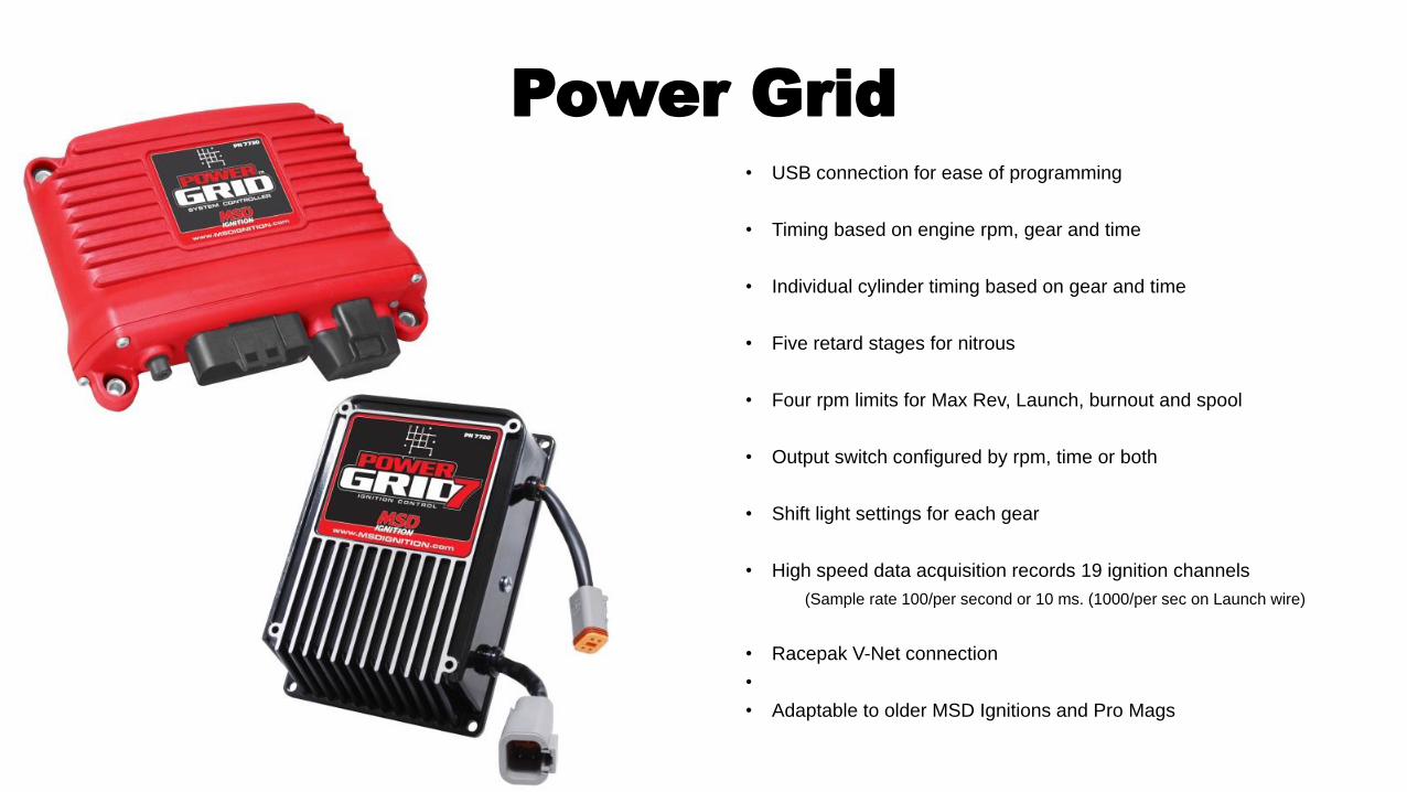
Power Grid
• USB connection for ease of programming
• Timing based on engine rpm, gear and time
• Individual cylinder timing based on gear and time
• Five retard stages for nitrous
• Four rpm limits for Max Rev, Launch, burnout and spool
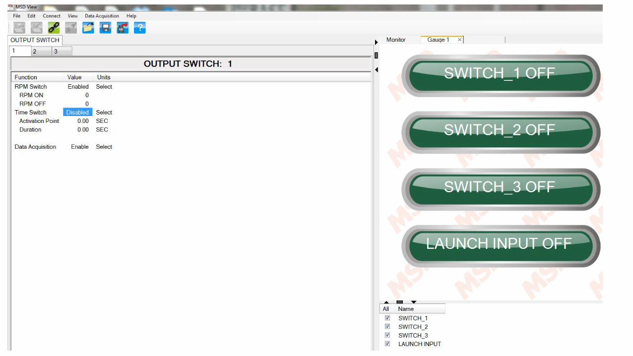
• Output switch configured by rpm, time or both
• Shift light settings for each gear
• High speed data acquisition records 19 ignition channels
(Sample rate 100/per second or 10 ms. (1000/per sec on Launch wire)
• Racepak V-Net connection
•
• Adaptable to older MSD Ignitions and Pro Mags
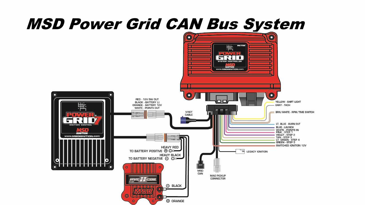
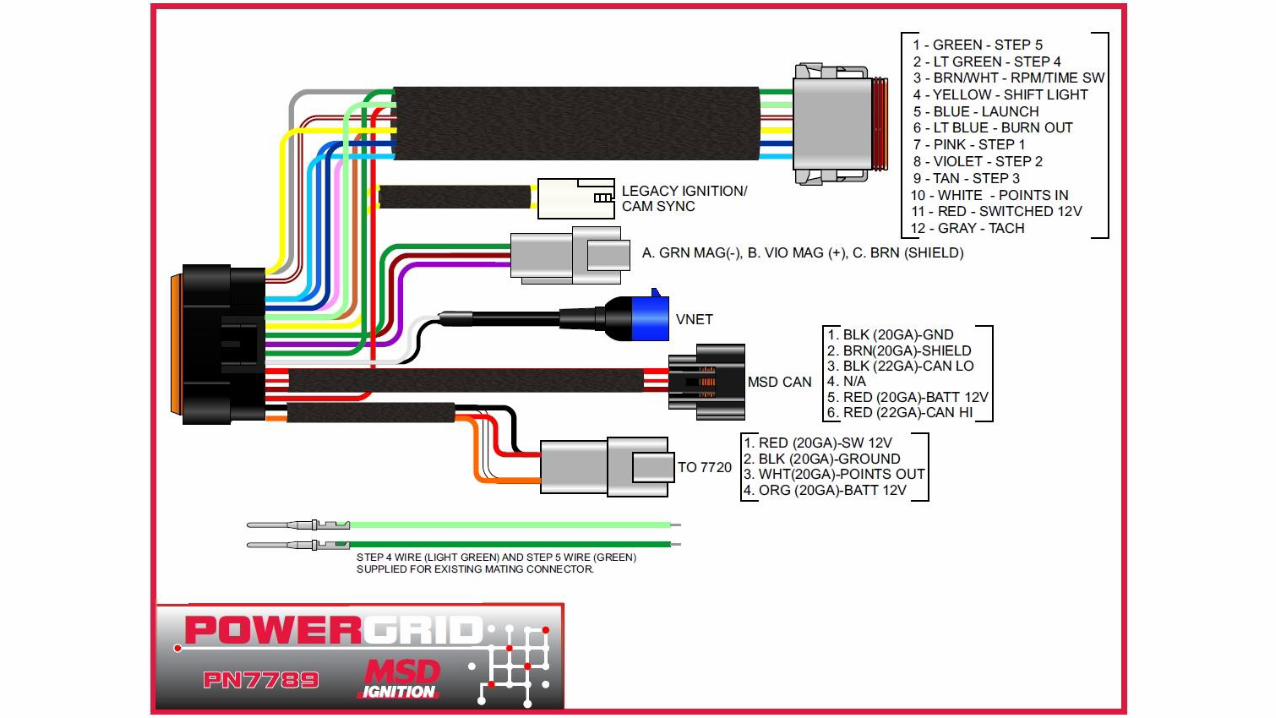
MSD Power Grid CAN Bus System
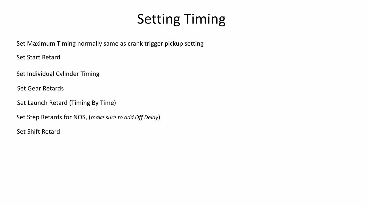
Setting Timing
Set Maximum Timing normally same as crank trigger pickup setting
Set Start Retard
Set Gear Retards
Set Step Retards for NOS, (make sure to add Off Delay)
Set Shift Retard
Set Individual Cylinder Timing
Set Launch Retard (Timing By Time)
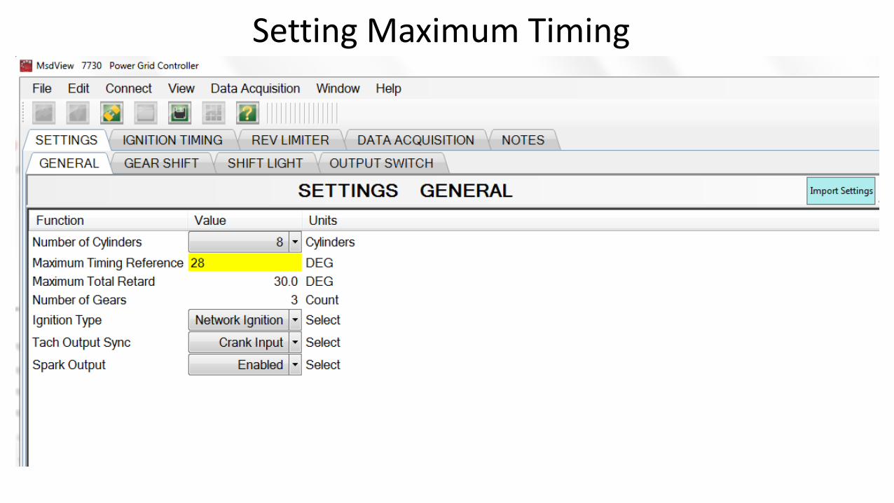
Setting Maximum Timing
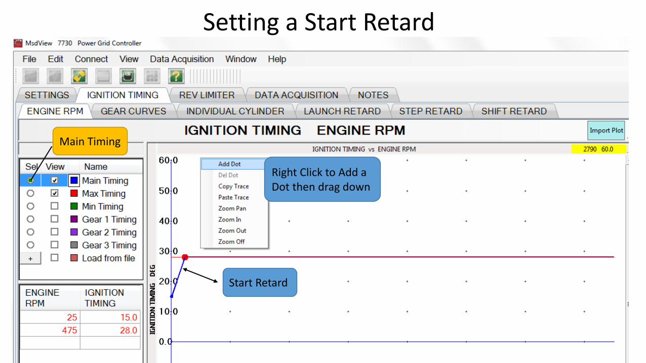
Setting a Start Retard
Start Retard
Right Click to Add a Dot then drag down
Main Timing
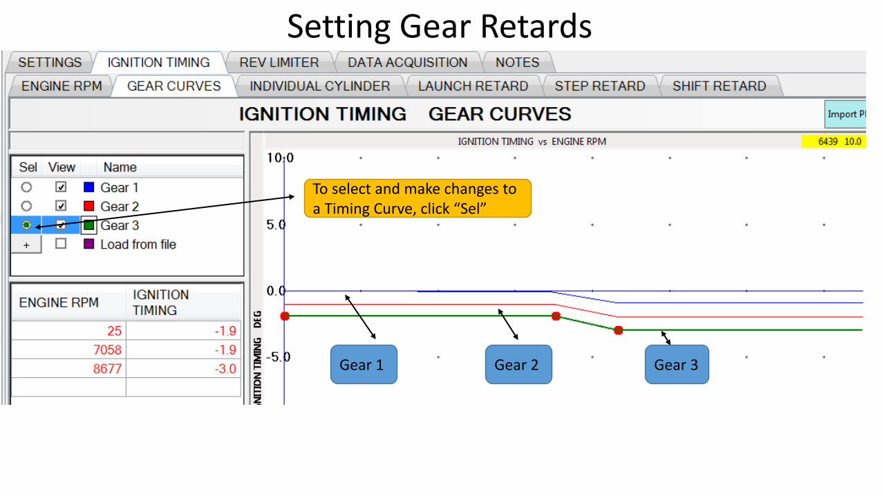
Setting Gear Retards
Gear 1 Gear 2 Gear 3
To select and make changes to a Timing Curve, click “Sel”
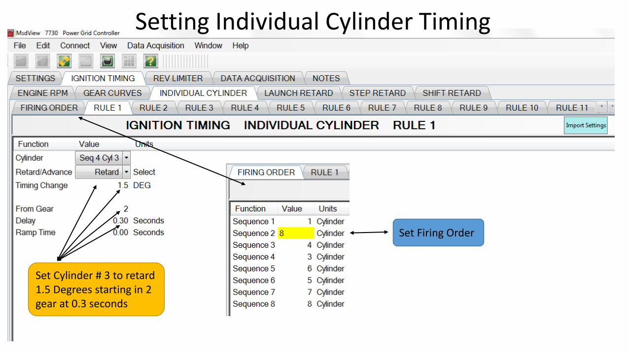
Setting Individual Cylinder Timing
Set Firing Order
Set Cylinder # 3 to retard 1.5 Degrees starting in 2 gear at 0.3 seconds
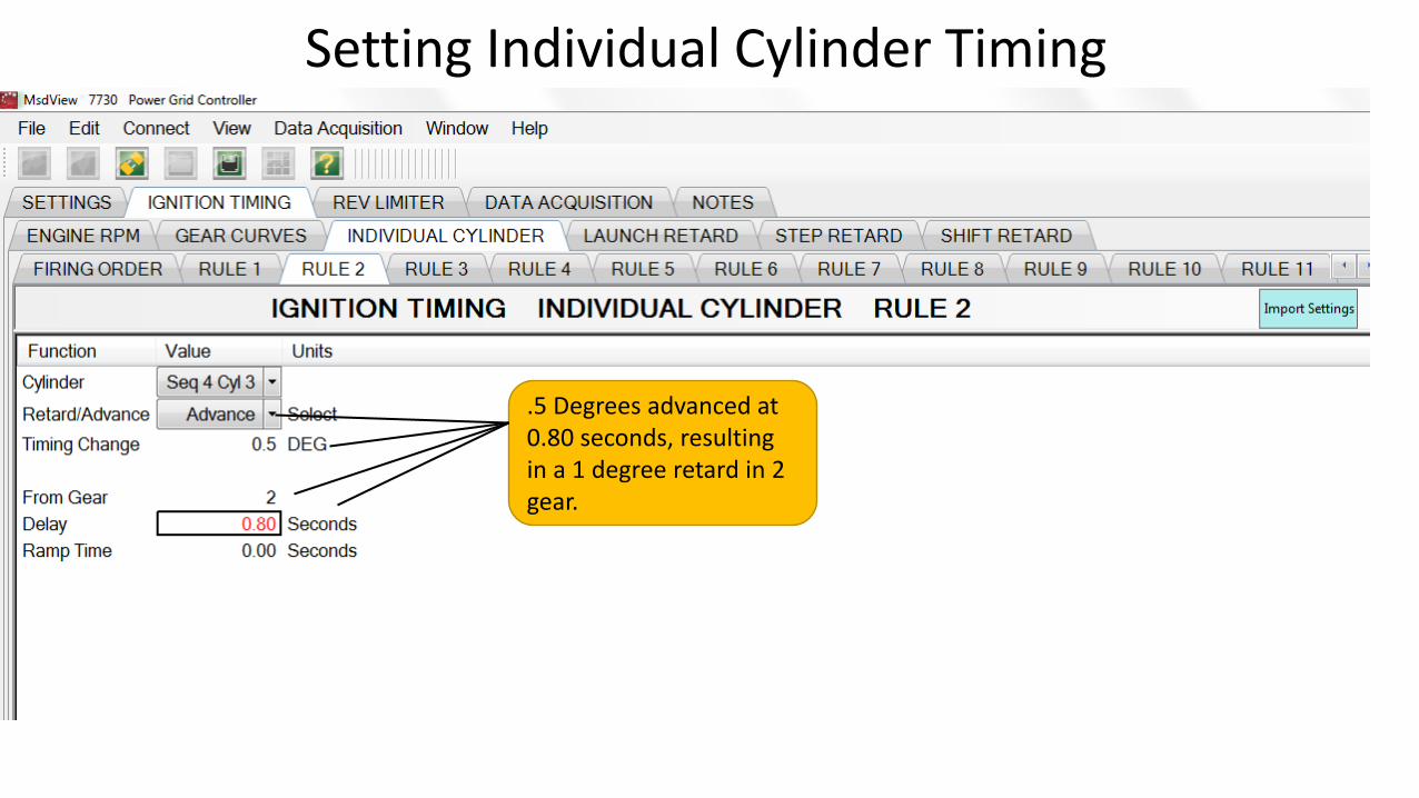
Setting Individual Cylinder Timing
.5 Degrees advanced at 0.80 seconds, resulting in a 1 degree retard in 2 gear.
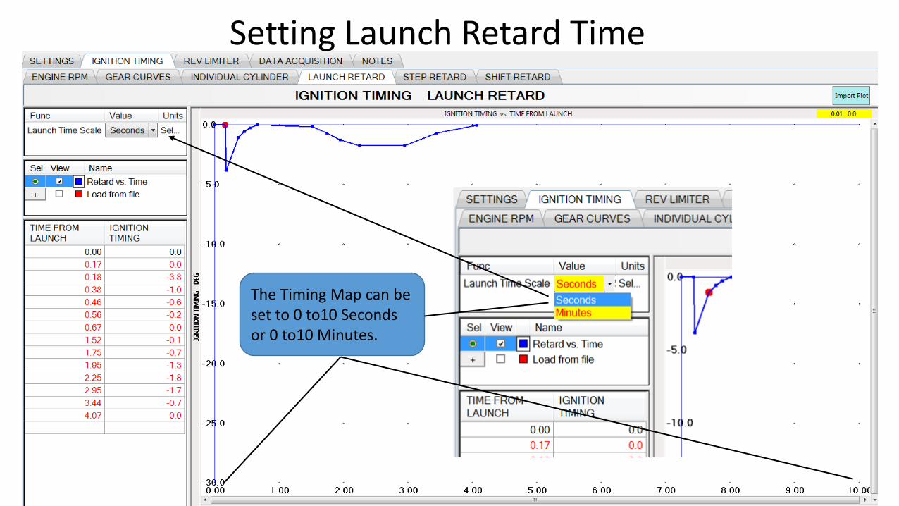
Setting Launch Retard Time
The Timing Map can be set to 0 to10 Seconds or 0 to10 Minutes.
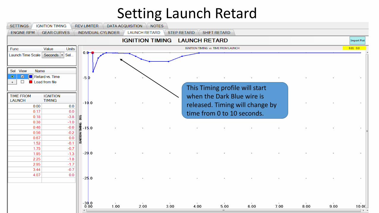
Setting Launch Retard
This Timing profile will start when the Dark Blue wire is released. Timing will change by time from 0 to 10 seconds.
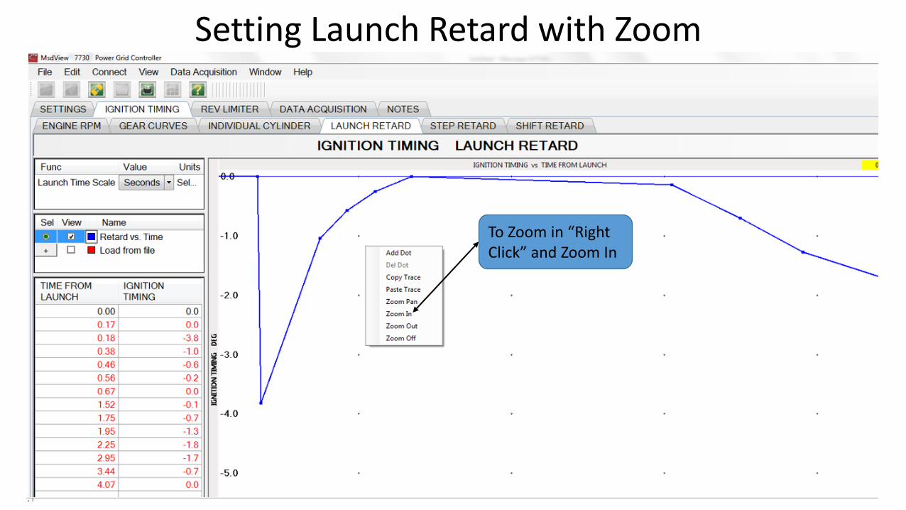
Setting Launch Retard with Zoom
To Zoom in “Right Click” and Zoom In
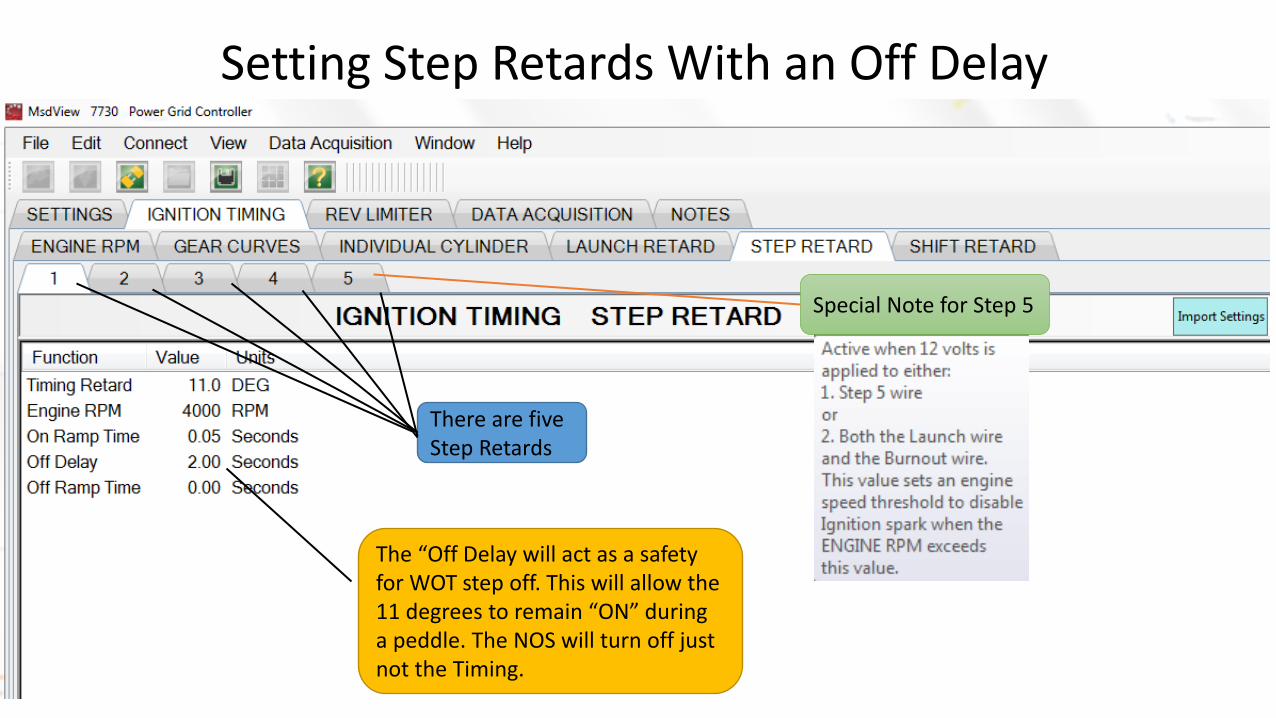
Setting Step Retards With an Off Delay
The “Off Delay will act as a safety for WOT step off. This will allow the 11 degrees to remain “ON” during a peddle. The NOS will turn off just not the Timing.
There are five Step Retards
Special Note for Step 5
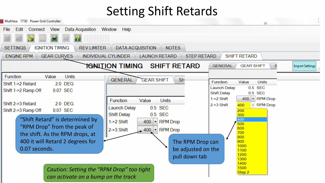
Setting Shift Retards
“Shift Retard” is determined by “RPM Drop” from the peak of the shift. As the RPM drops, at 400 it will Retard 2 degrees for 0.07 seconds.
The RPM Drop can be adjusted on the pull down tab
Caution: Setting the “RPM Drop” too tight can activate on a bump on the track
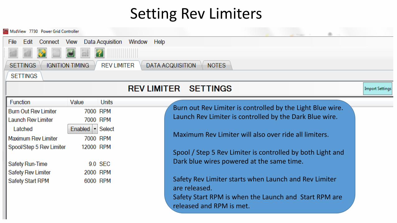
Setting Rev Limiters
Burn out Rev Limiter is controlled by the Light Blue wire.Launch Rev Limiter is controlled by the Dark Blue wire.
Maximum Rev Limiter will also over ride all limiters.
Spool / Step 5 Rev Limiter is controlled by both Light and Dark blue wires powered at the same time.
Safety Rev Limiter starts when Launch and Rev Limiter are released.Safety Start RPM is when the Launch and Start RPM are released and RPM is met.
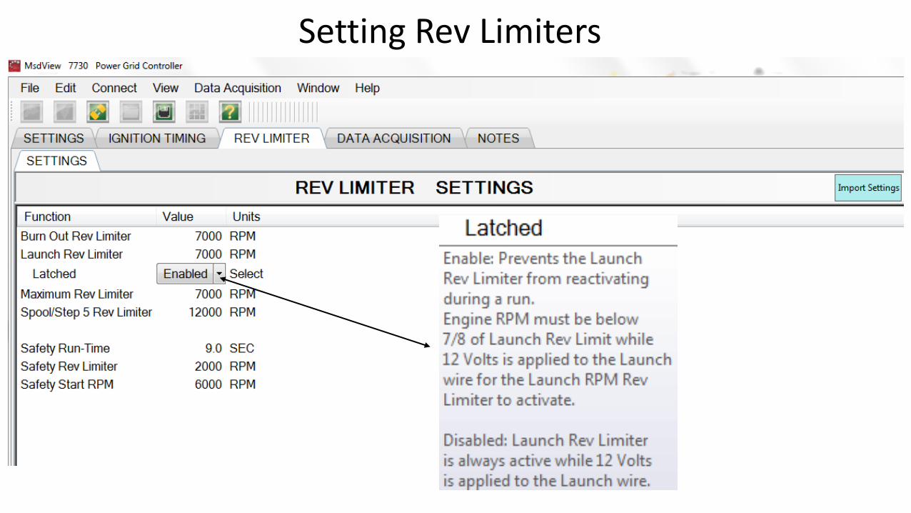
Setting Rev Limiters
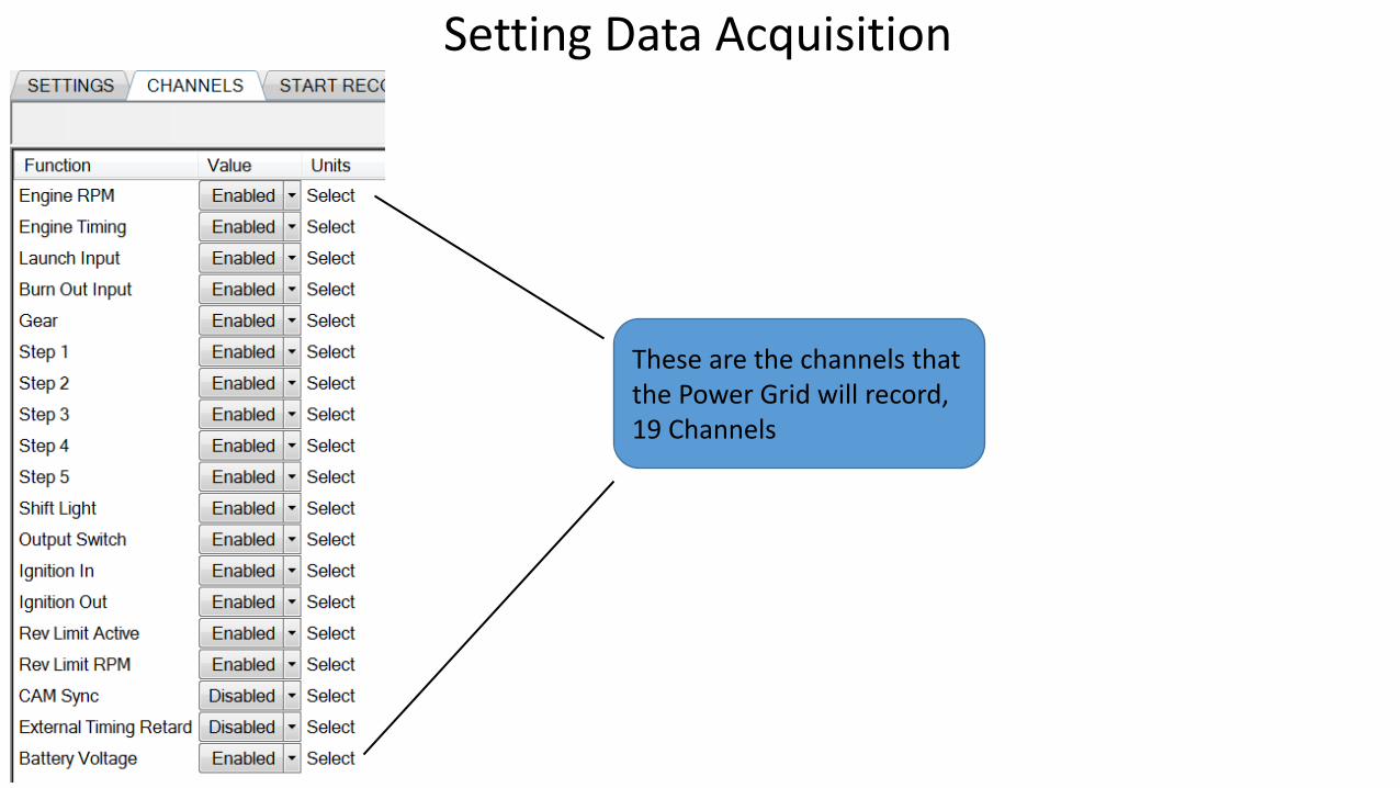
Setting Data Acquisition
These are the channels that the Power Grid will record,19 Channels
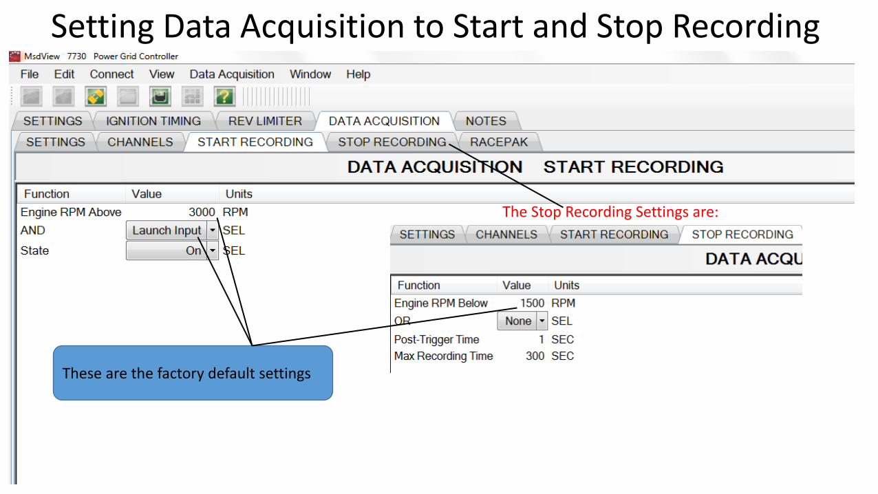
Setting Data Acquisition to Start and Stop Recording
The Stop Recording Settings are:
These are the factory default settings
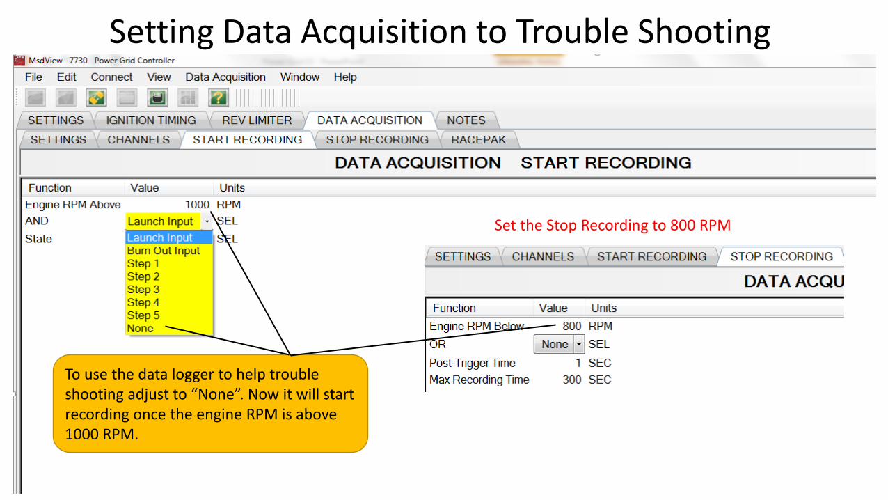
Setting Data Acquisition to Trouble Shooting
To use the data logger to help trouble shooting adjust to “None”. Now it will start recording once the engine RPM is above 1000 RPM.
Set the Stop Recording to 800 RPM
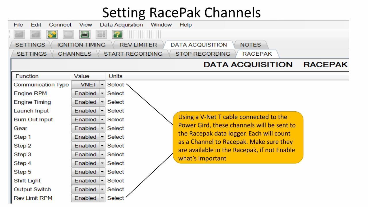
Setting RacePak Channels
Using a V-Net T cable connected to the Power Gird, these channels will be sent to the Racepak data logger. Each will count as a Channel to Racepak. Make sure they are available in the Racepak, if not Enable what’s important
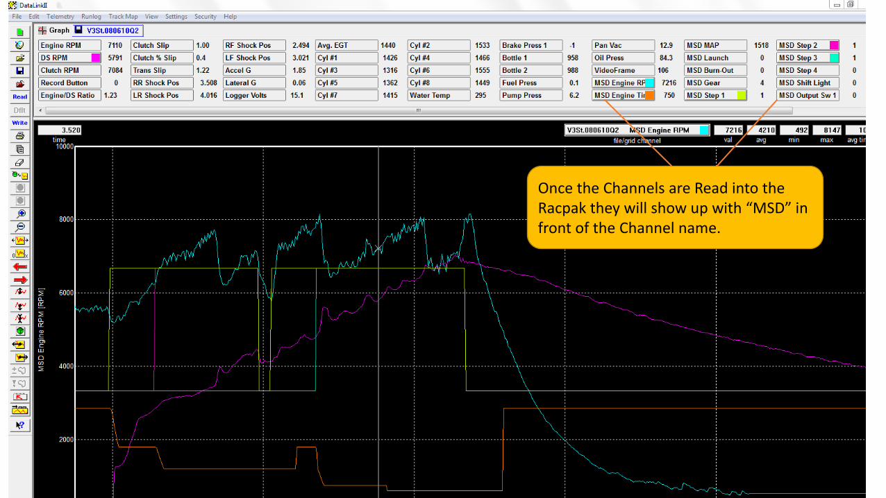
Once the Channels are Read into the Racpak they will show up with “MSD” in front of the Channel name.
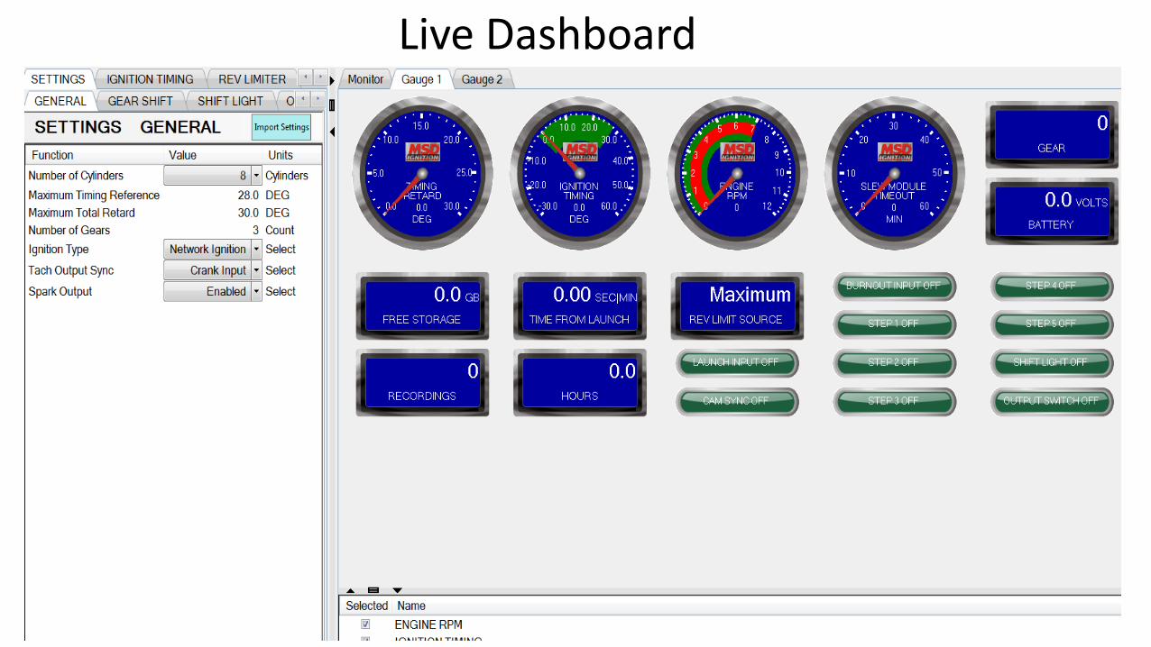
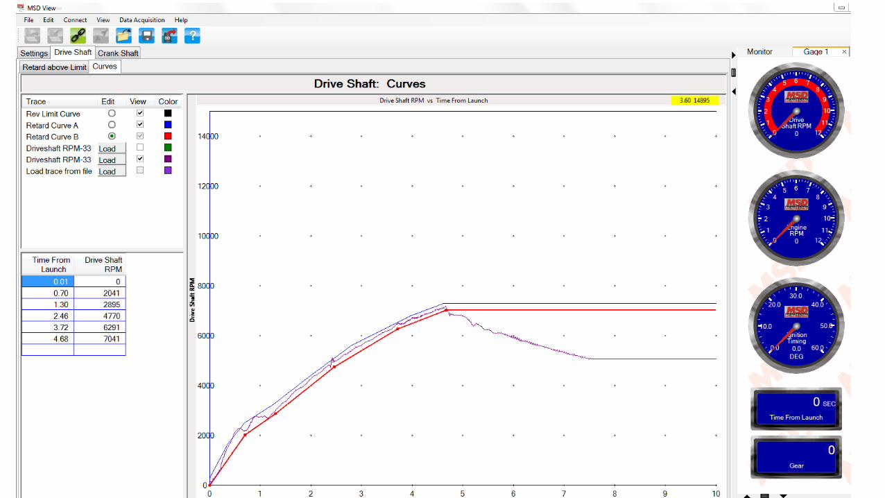
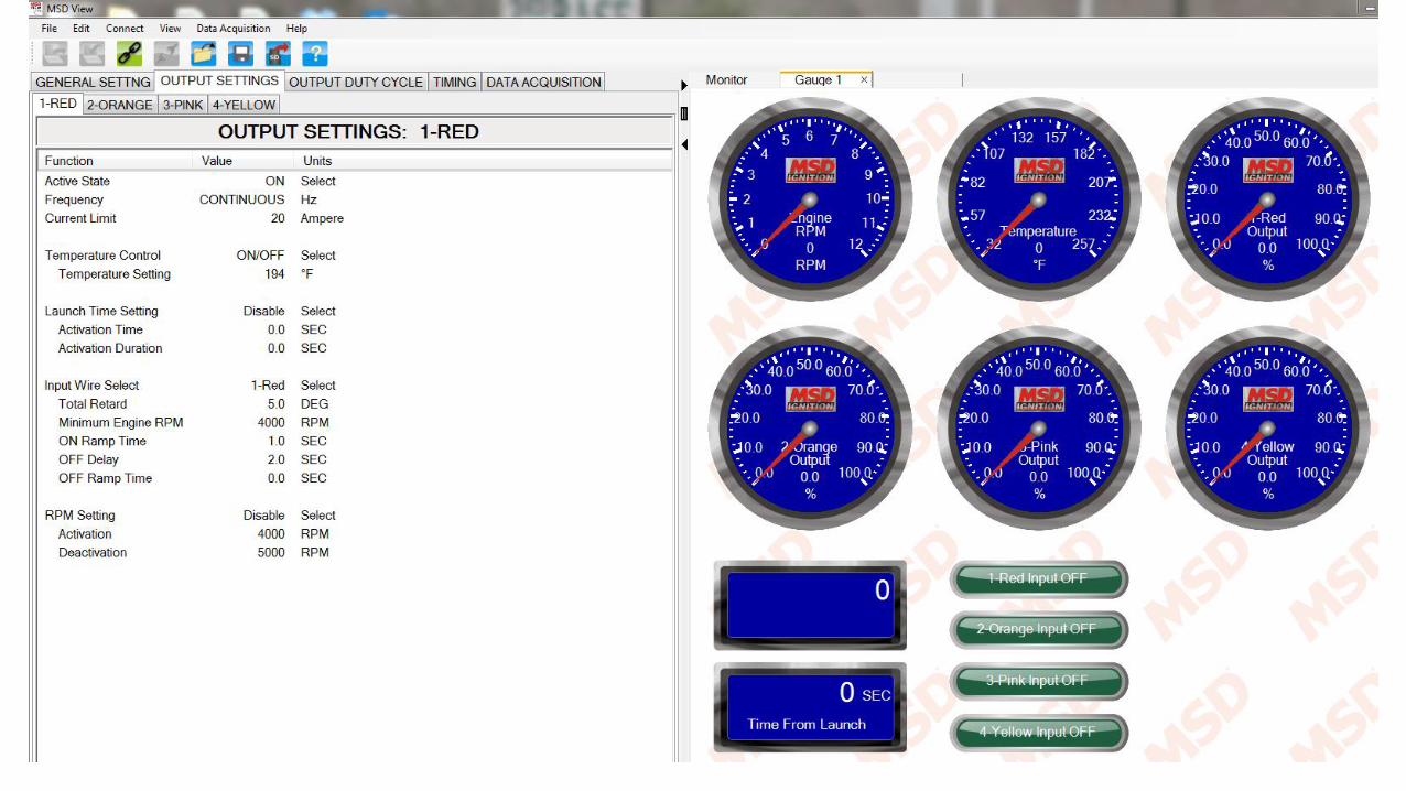
Live Dashboard
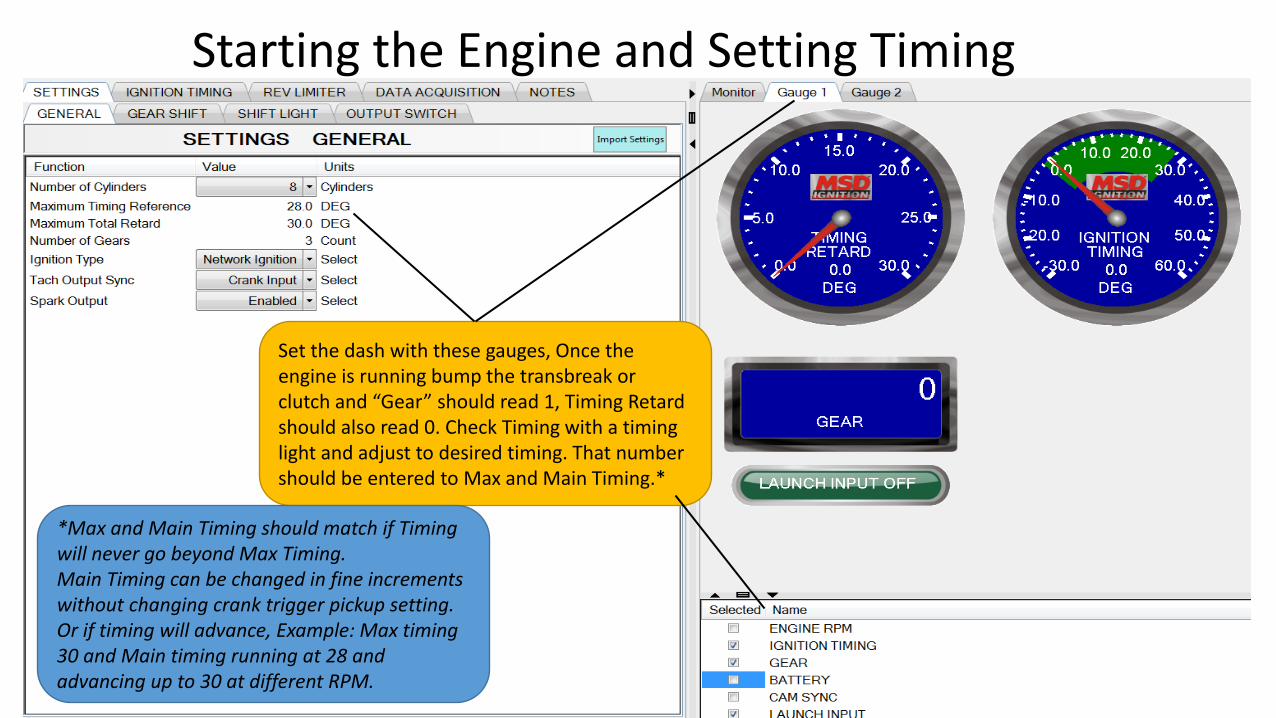
Starting the Engine and Setting Timing
Set the dash with these gauges, Once the engine is running bump the transbreak or clutch and “Gear” should read 1, Timing Retard should also read 0. Check Timing with a timing light and adjust to desired timing. That number should be entered to Max and Main Timing.*
*Max and Main Timing should match if Timing will never go beyond Max Timing.Main Timing can be changed in fine increments without changing crank trigger pickup setting. Or if timing will advance, Example: Max timing 30 and Main timing running at 28 and advancing up to 30 at different RPM.
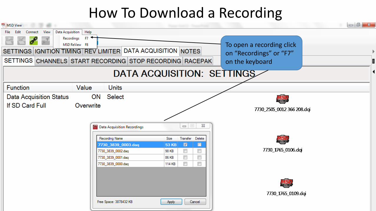
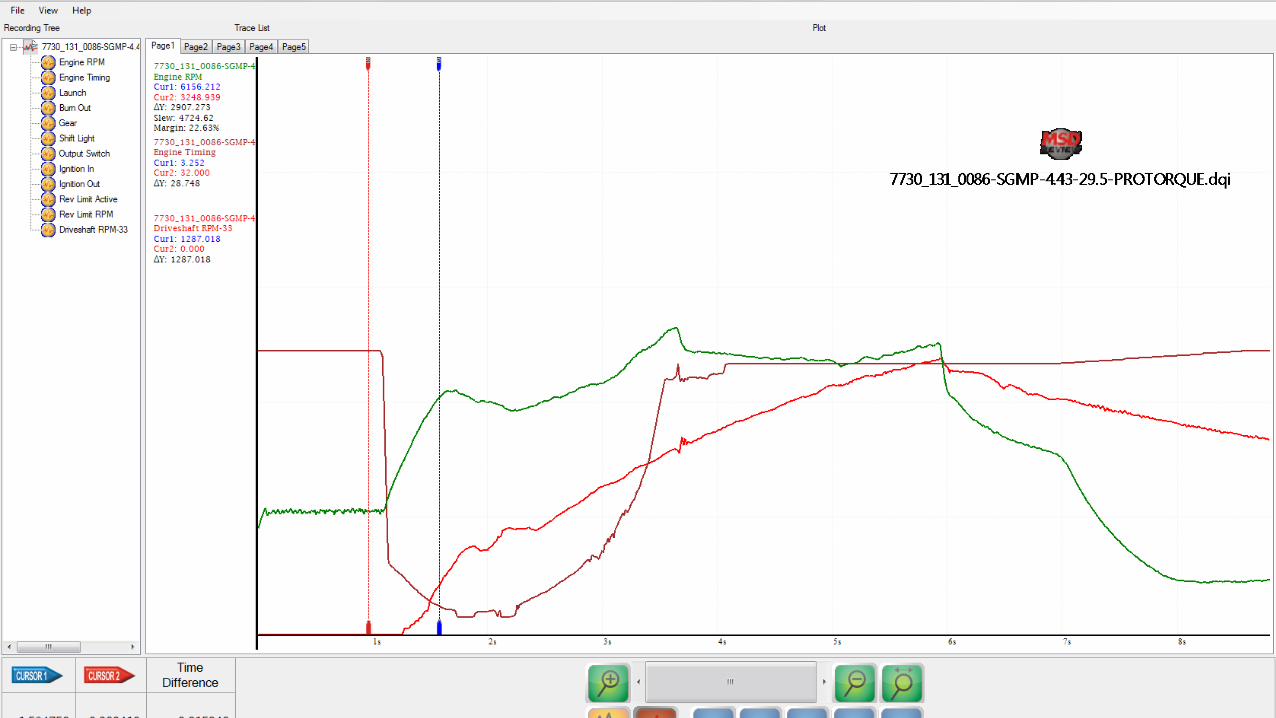
How To Download a Recording
To open a recording click on “Recordings” or “F7” on the keyboard
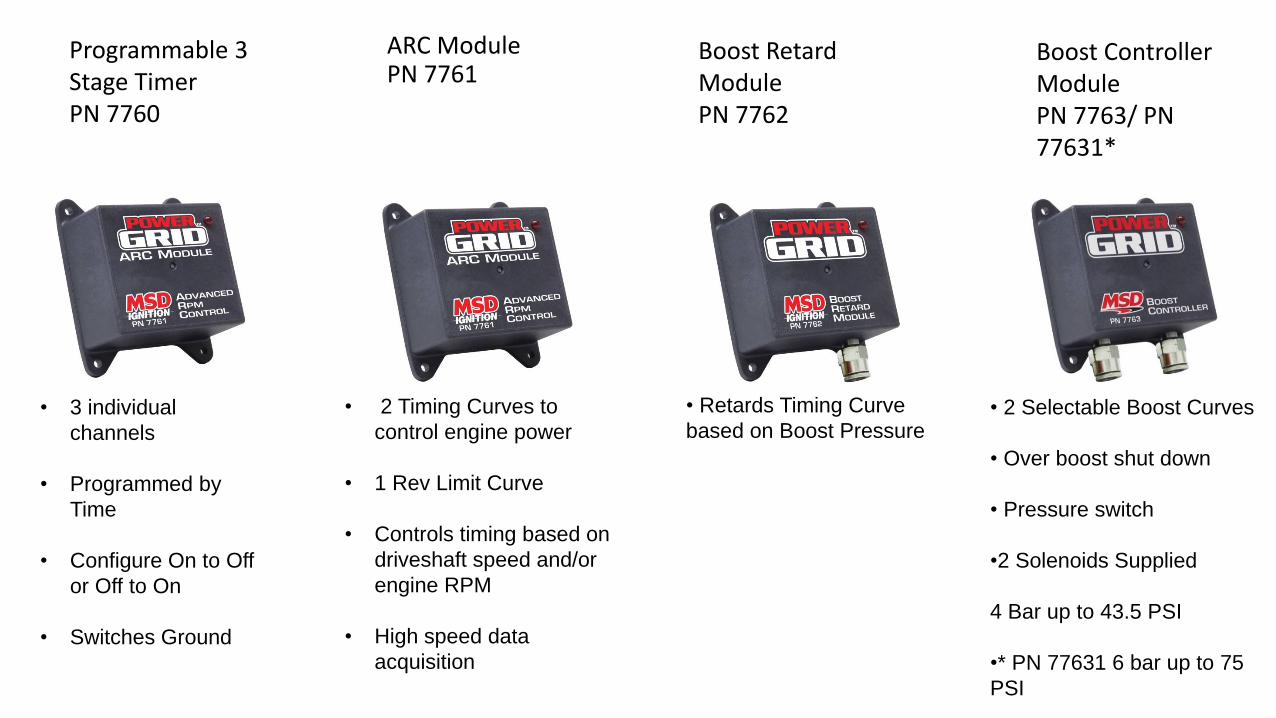
ARC ModulePN 7761
Boost Retard ModulePN 7762
Boost Controller ModulePN 7763/ PN 77631*
• 2 Timing Curves to
control engine power
• 1 Rev Limit Curve
• Controls timing based on
driveshaft speed and/or
engine RPM
• High speed data
acquisition
• Retards Timing Curve
based on Boost Pressure• 2 Selectable Boost Curves
• Over boost shut down
• Pressure switch
•2 Solenoids Supplied
4 Bar up to 43.5 PSI
•* PN 77631 6 bar up to 75
PSI
Programmable 3 Stage Timer PN 7760
• 3 individual
channels
• Programmed by
Time
• Configure On to Off
or Off to On
• Switches Ground
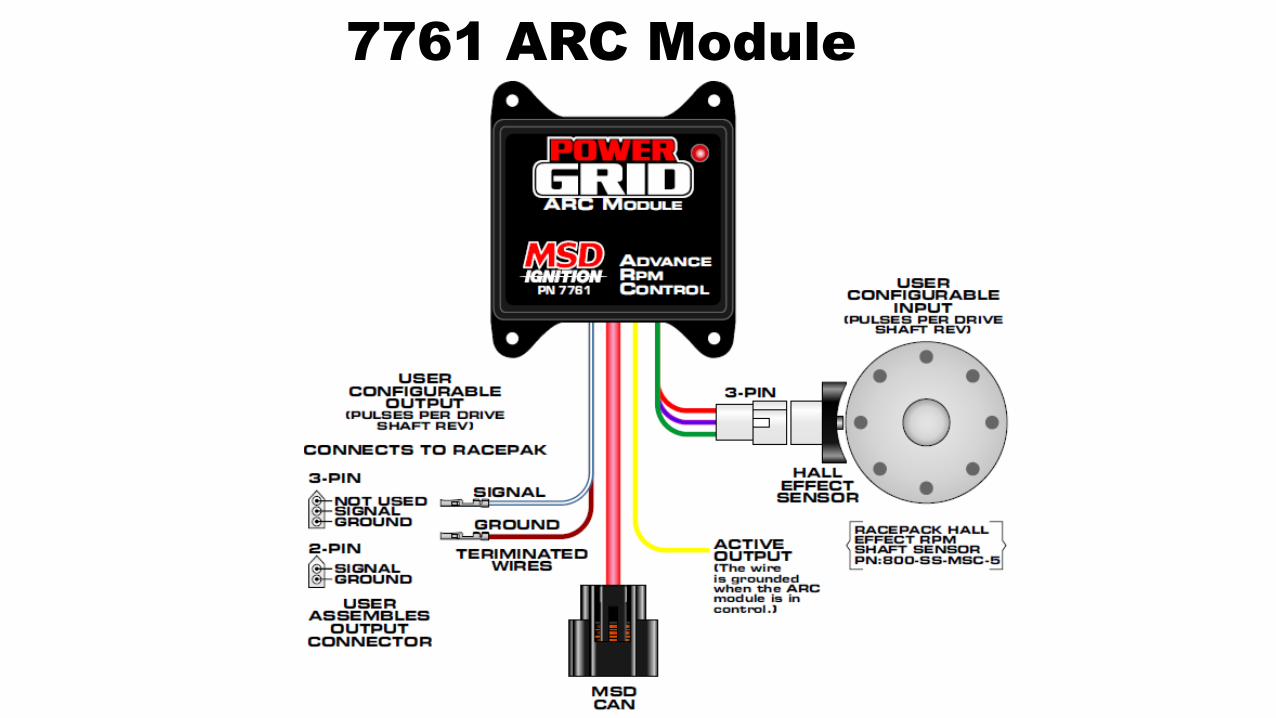
7761 ARC Module
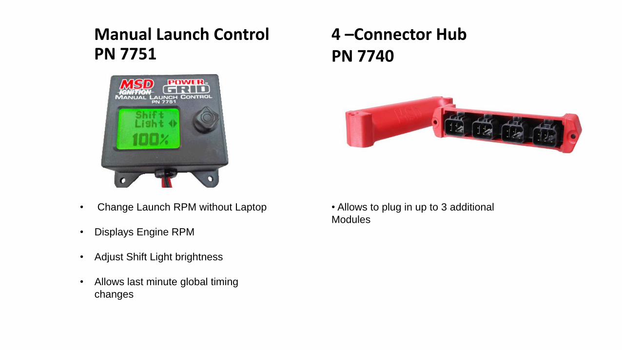
Manual Launch ControlPN 7751
4 –Connector Hub PN 7740
• Change Launch RPM without Laptop
• Displays Engine RPM
• Adjust Shift Light brightness
• Allows last minute global timing
changes
• Allows to plug in up to 3 additional
Modules
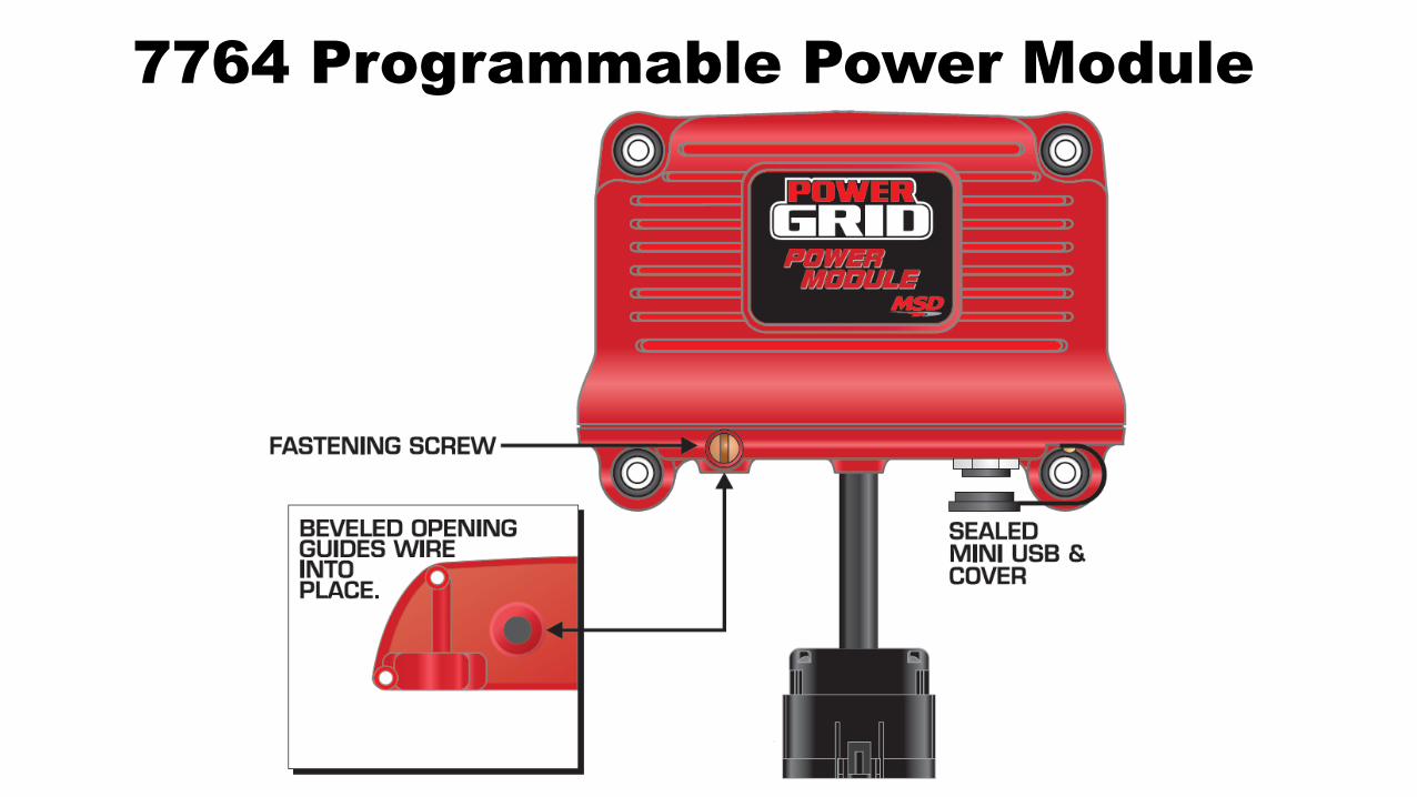
7764 Programmable Power Module
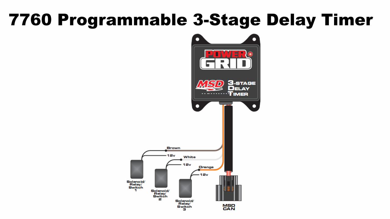
7760 Programmable 3-Stage Delay Timer
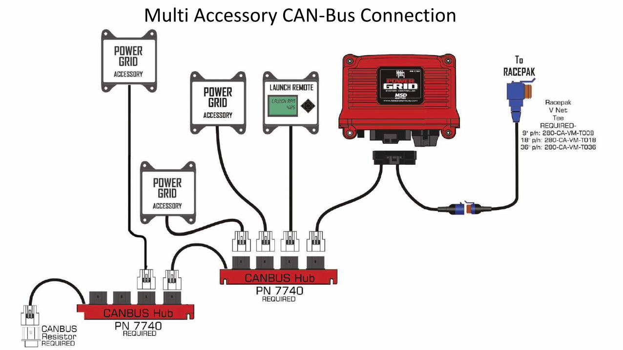
Multi Accessory CAN-Bus Connection