Power Generation Cycles Vapor Power Generation The Rankine ... · Lecture 24 Power Generation...
20
Department of Mechanical Engineering ME 322 – Mechanical Engineering Thermodynamics Lecture 24 Power Generation Cycles Vapor Power Generation The Rankine Cycle
Transcript of Power Generation Cycles Vapor Power Generation The Rankine ... · Lecture 24 Power Generation...

Department of Mechanical Engineering
ME 322 – Mechanical Engineering
Thermodynamics
Lecture 24
Power Generation Cycles
Vapor Power Generation
The Rankine Cycle

Power Generation Cycles
• Vapor Power Generation Cycles
– Working fluid experiences a phase change
– Example: Steam Power Plant
• Gas Power Generation Cycles
– Working fluid stays in the vapor or gas phase
– Example: Gas Turbine Engine
• Internal Combustion Engine (ICE) Cycles
– The working fluid is air in a closed piston-cylinder
– Example: Spark ignition ICE
– Example: Compression ignition ICE
2

A Simple Vapor Power Plant
In ME 322, we are concerned
with subsystem A
3

The Rankine Cycle - Components
(Heat Exchanger)
(Heat Exchanger)
4

The Rankine Cycle – A Heat Engine
net cycleW W
LT
HTHT
LT
(Heat Source)
(Heat Sink)
5

Component Analysis
1 2tW m h h
Turbine
2 3outQ m h h
Condenser
4 3pW m h h
Pump
1 4inQ m h h
Boiler 5
6
w
6
6 5
6 5
out w
out w p
Q m h h
Q m c T T

Performance Parameters
Thermal Efficiency
energy sought
energy that costs $$th
Heat Rate
energy input to the cycle (Btu)HR
net work output (kW-hr)
Back Work Ratio
pump work requiredbwr
turbine work delivered
7
1 2 4 3 1 2 4 3
1 4 1 4
t p
in
m h h m h h h h h hW W
Q m h h h h
1 4
1 2 4 3
[Btu/hr][Btu/hr]
kW kW
in
t p
h hQ
W W h h h h
4 3 4 3
1 2 1 2
p
t
m h h h hW
W m h h h h

Department of Mechanical Engineering
ME 322 – Mechanical Engineering
Thermodynamics
Vapor Power Generation
The Ideal Rankine Cycle
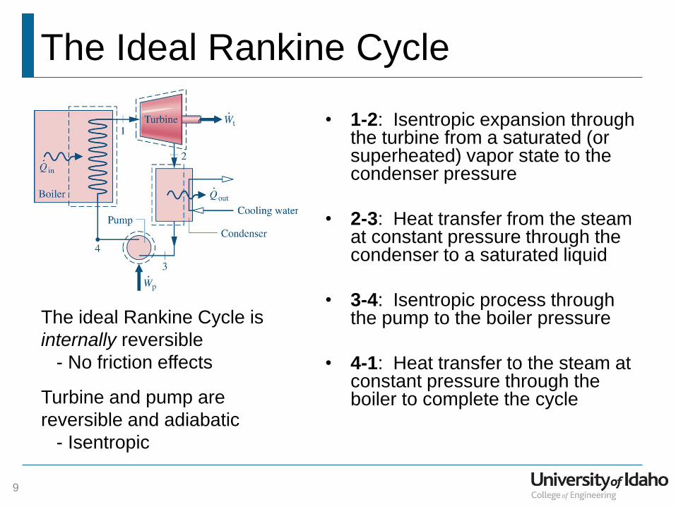
The Ideal Rankine Cycle
• 1-2: Isentropic expansion through the turbine from a saturated (or superheated) vapor state to the condenser pressure
• 2-3: Heat transfer from the steam at constant pressure through the condenser to a saturated liquid
• 3-4: Isentropic process through the pump to the boiler pressure
• 4-1: Heat transfer to the steam at constant pressure through the boiler to complete the cycle
The ideal Rankine Cycle is
internally reversible
- No friction effects
Turbine and pump are
reversible and adiabatic
- Isentropic
9

The Ideal Rankine Cycle
HP
LP
Boiler pressure
Condenser pressure
The ideal cycle also includes the possibility
of superheating the saturated vapor
10

Department of Mechanical Engineering
ME 322 – Mechanical Engineering
Thermodynamics
Example
Ideal Rankine Cycle with Superheat

Ideal Rankine Cycle with Superheat
Given: An ideal Rankine Cycle with water as the working
fluid with known properties as shown below.
Find:
(a) The net power
developed (Btu/hr)
(b) The thermal efficiency
(c) The heat rate
(d) The back work ratio
(e) The mass flow rate of
the cooling water
1
16
1600 psia1100 F
1.4 10 lbm/hr
PT
m
2 1 psiaP
5 60 FT
6 80 FT
12

Ideal Rankine Cycle with Superheat
1
16
1600 psia1100 F
1.4 10 lbm/hr
PT
m
2 1 psiaP
5 60 FT
6 80 FT
13

Ideal Rankine Cycle with Superheat
14
1
16
1600 psia1100 F
1.4 10 lbm/hr
PT
m
2 1 psiaP
5 60 FT
6 80 FT
The net power delivered from the
cycle is,
net t pW W W
The First Law applied to the turbine
1 2tW m h h
The enthalpy at the exit of the turbine can be found because
the turbine is isentropic,

Ideal Rankine Cycle with Superheat
15
1
16
1600 psia1100 F
1.4 10 lbm/hr
PT
m
2 1 psiaP
5 60 FT
6 80 FT
The First Law applied to the pump,
4 3pW m h h

Ideal Rankine Cycle with Superheat
16
1
16
1600 psia1100 F
1.4 10 lbm/hr
PT
m
2 1 psiaP
5 60 FT
6 80 FT
The thermal efficiency of the cycle is,
netth
in
W
Q
The heat transfer rate at the boiler is
determined from the First Law,
1 4inQ m h h

Ideal Rankine Cycle with Superheat
17
1
16
1600 psia1100 F
1.4 10 lbm/hr
PT
m
2 1 psiaP
5 60 FT
6 80 FT
The heat rate and back work ratio
are defined as,
[Btu/hr]
HRkW
in
net
Q
W bwr
p
t
W
W
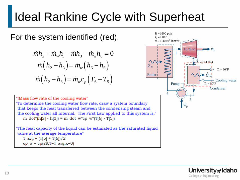
To determine the mass flow rate of the cooling water, draw a
system boundary around the condenser that keeps the heat
transfer all internal.
Ideal Rankine Cycle with Superheat
18
1
16
1600 psia1100 F
1.4 10 lbm/hr
PT
m
2 1 psiaP
5 60 FT
6 80 FT
For the system identified (red),
2 5 3 6 0w wmh m h mh m h
2 3 6 5w pm h h m c T T
2 3 6 5wm h h m h h
Ideal Rankine Cycle with Superheat
19
1
16
1600 psia1100 F
1.4 10 lbm/hr
PT
m
2 1 psiaP
5 60 FT
6 80 FT
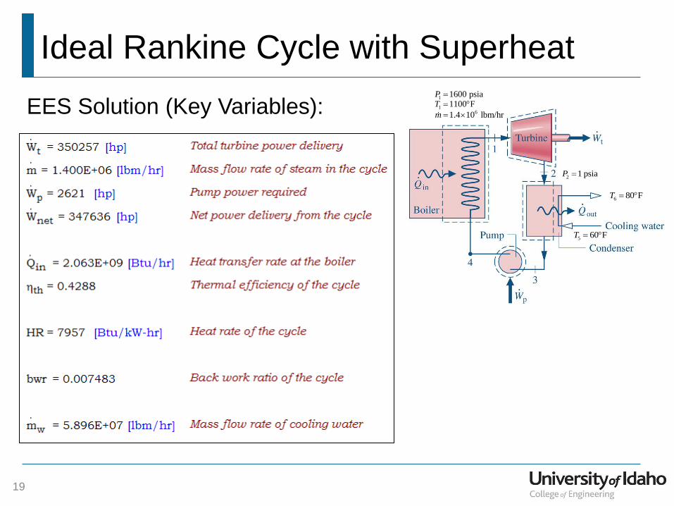
EES Solution (Key Variables):

Ideal Rankine Cycle with Superheat
20
1
16
1600 psia1100 F
1.4 10 lbm/hr
PT
m
2 1 psiaP
5 60 FT
6 80 FT
= 891.2 MBtu/hr
(350,257 hp)
= 1178 MBtu/hr
= 6.7 MBtu/hr
2063 MBtu/hr =
891.2 6.7 MBtu/hr0.429
2063 M/Btuhrth
6.7 MBtu/hrbwr 0.0075
891.2 MBtu/hr
2063 MBtu/hr 3412 Btu/hr
HR891.2 6.7 MBtu/hr kW
BtuHR 7958
kW-hr
Results: