Power Factor Correction Solutions & Applications...Power Factor Correction – 105 kVAR kVAR Added...
82
© 2012 Eaton Corporation. All rights reserved. Power Factor Correction Solutions & Applications Rick Orman Americas Sales Manager Power Factor Correction/Surge Protection/Power Conditioning
Transcript of Power Factor Correction Solutions & Applications...Power Factor Correction – 105 kVAR kVAR Added...

© 2012 Eaton Corporation. All rights reserved.
Power Factor Correction Solutions & Applications
Rick Orman
Americas Sales Manager
Power Factor Correction/Surge
Protection/Power Conditioning

2 © 2012 Eaton Corporation. All rights reserved. 2
Power factor definition
• “Real” power = working power = kW
• “Apparent” power = Volts x Amps = kVA
• “Reactive” power = magnetizing power = kVAR
kVA
kVAr
kW
• Power factor is the
ratio between the
“real” power and the
“apparent” power of an
electrical system
3 © 2012 Eaton Corporation. All rights reserved. 3
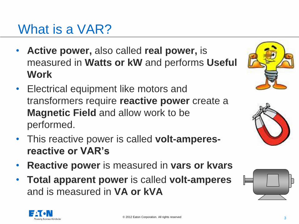
What is a VAR?
• Active power, also called real power, is
measured in Watts or kW and performs Useful
Work
• Electrical equipment like motors and
transformers require reactive power create a
Magnetic Field and allow work to be
performed.
• This reactive power is called volt-amperes-
reactive or VAR’s
• Reactive power is measured in vars or kvars
• Total apparent power is called volt-amperes
and is measured in VA or kVA

5 © 2012 Eaton Corporation. All rights reserved. 5
Somebody has to pay for capacity and losses
Capacity
(kVA)
Wasted Capacity
(VAR’s)
Useful Work
(Watts)

6 © 2012 Eaton Corporation. All rights reserved. 6
Typical Sources of Low Power Factor
• Reactive power is required by many loads to
provide magnetizing current for:
• Motors
• Power transformers
• Welding machines
• Electric arc furnaces
• Inductors
• Lighting ballasts

7 © 2012 Eaton Corporation. All rights reserved. 7
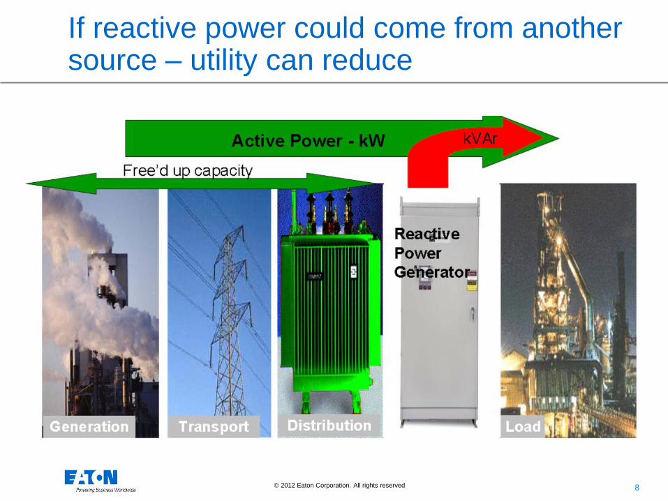
Utility must generate, transmit, and distribute active AND reactive power
8 © 2012 Eaton Corporation. All rights reserved.
If reactive power could come from another source – utility can reduce

10 © 2012 Eaton Corporation. All rights reserved.
What are these magical capacitors?

11 © 2012 Eaton Corporation. All rights reserved.
What are these magical capacitors?

12 © 2012 Eaton Corporation. All rights reserved.
What are these magical capacitors?

13 © 2012 Eaton Corporation. All rights reserved.
What are these magical capacitors?
Gas Pressure

14 © 2012 Eaton Corporation. All rights reserved. 14
Why Consider PFC?
PF correction provides many benefits:
• Primary Benefit:
• Reduced electric utility bill if there is a penalty
• Other Benefits:
• Increased system capacity (generators, cables, transformers)
• Reduced losses in transformers and cables
• Improved voltage regulation
• Greening the power system
15 © 2012 Eaton Corporation. All rights reserved. 15
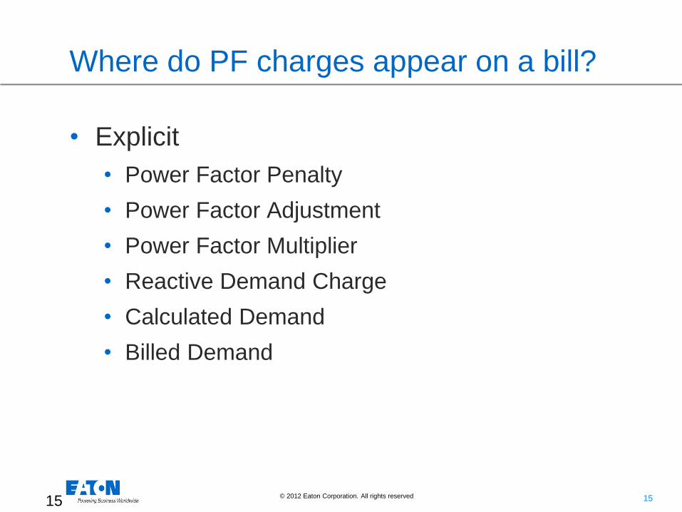
Where do PF charges appear on a bill?
• Explicit
• Power Factor Penalty
• Power Factor Adjustment
• Power Factor Multiplier
• Reactive Demand Charge
• Calculated Demand
• Billed Demand
16 © 2012 Eaton Corporation. All rights reserved. 16
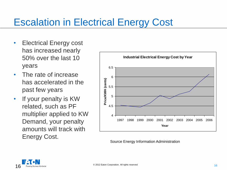
Escalation in Electrical Energy Cost
• Electrical Energy cost
has increased nearly
50% over the last 10
years
• The rate of increase
has accelerated in the
past few years
• If your penalty is KW
related, such as PF
multiplier applied to KW
Demand, your penalty
amounts will track with
Energy Cost.
Industrial Electrical Energy Cost by Year
4
4.5
5
5.5
6
6.5
1997 1998 1999 2000 2001 2002 2003 2004 2005 2006
Year
Pri
ce/K
WH
(cen
ts)
Source Energy Information Administration
17 © 2012 Eaton Corporation. All rights reserved. 17
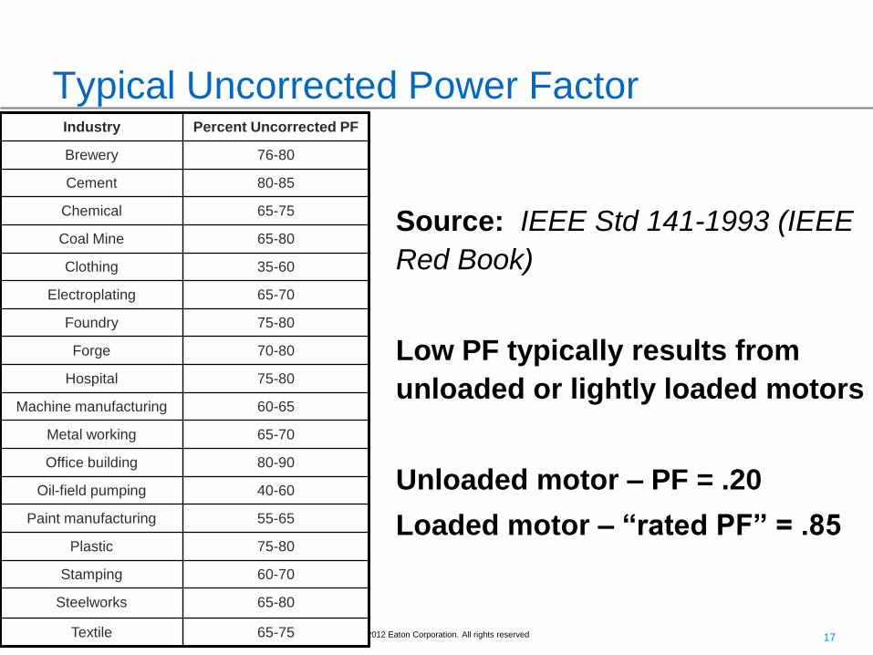
Typical Uncorrected Power Factor
Source: IEEE Std 141-1993 (IEEE
Red Book)
Low PF typically results from
unloaded or lightly loaded motors
Unloaded motor – PF = .20
Loaded motor – “rated PF” = .85
Industry Percent Uncorrected PF
Brewery 76-80
Cement 80-85
Chemical 65-75
Coal Mine 65-80
Clothing 35-60
Electroplating 65-70
Foundry 75-80
Forge 70-80
Hospital 75-80
Machine manufacturing 60-65
Metal working 65-70
Office building 80-90
Oil-field pumping 40-60
Paint manufacturing 55-65
Plastic 75-80
Stamping 60-70
Steelworks 65-80
Textile 65-75
18 © 2012 Eaton Corporation. All rights reserved. 18
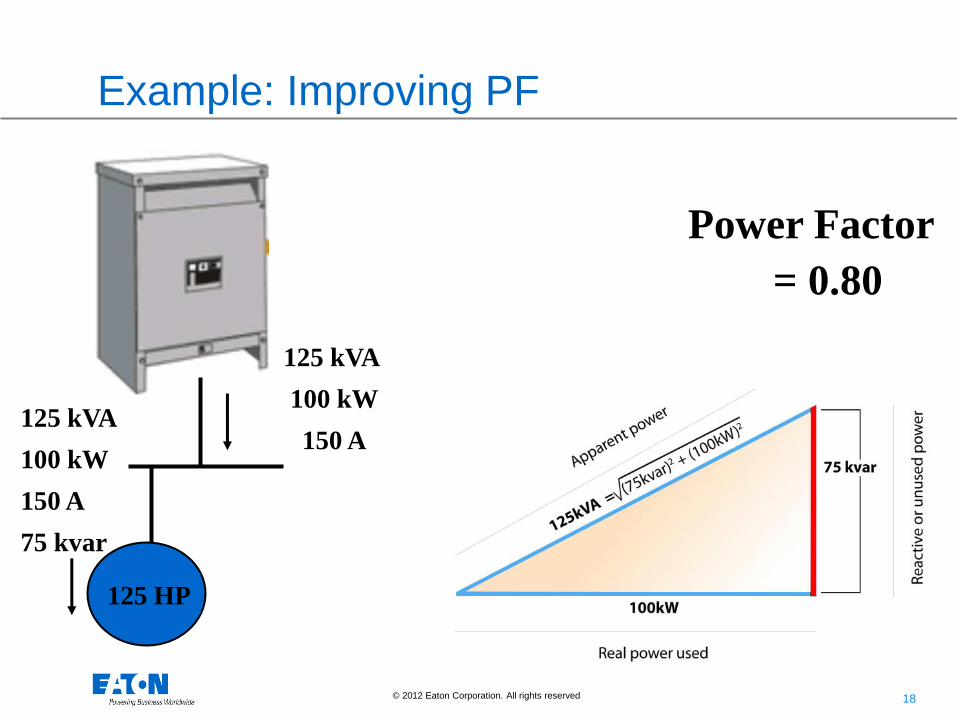
Example: Improving PF
125 HP
125 kVA
100 kW
150 A
75 kvar
125 kVA
100 kW
150 A
Power Factor
= 0.80

19 © 2012 Eaton Corporation. All rights reserved. 19
Example: Improving PF Cont.
125 HP 50 kvar
103 kVA
100 kW
124 A
25 kvar
Power Factor
0.80 ==> 0.97
125 kVA
100 kW
153 A
75 kvar

20 © 2012 Eaton Corporation. All rights reserved. 20
Cost savings due to increased capacity
• Correcting poor power
factor can significantly
reduce the load on
transformers and
conductors and allow
for facility expansion
• Transformers are rated
by kVA and must be
sized accordingly

21 © 2012 Eaton Corporation. All rights reserved. 21
Effect of Location
R2 R1
Motor
Load
Resistive
Load
Place here for utility PF penalty
Place here for utility PF penalty
(utility owned transformer)
or
Place here to reduce losses in
transformer or free capacity
Place here for line loss
reduction and voltage
improvement
22 © 2012 Eaton Corporation. All rights reserved.
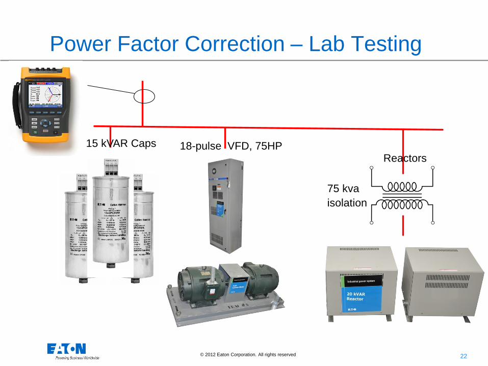
Power Factor Correction – Lab Testing
75 kva
isolation
Reactors 18-pulse VFD, 75HP 15 kVAR Caps
23 © 2012 Eaton Corporation. All rights reserved.
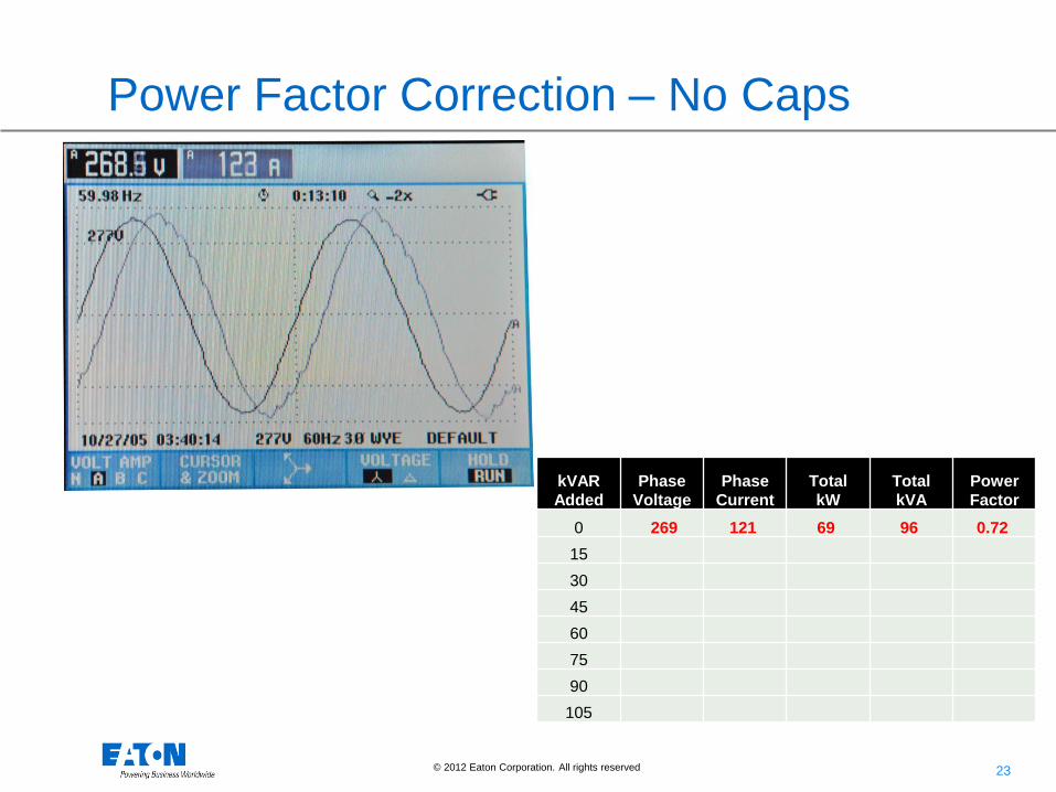
Power Factor Correction – No Caps
kVAR
Added Phase
Voltage Phase
Current Total
kW Total
kVA Power
Factor
0 269 121 69 96 0.72
15
30
45
60
75
90
105

24 © 2012 Eaton Corporation. All rights reserved.
Power Factor Correction – 15 kVAR
kVAR
Added Phase
Voltage Phase
Current Total
kW Total
kVA Power
Factor
0 269 121 69 96 0.72
15 268 109 69 84 0.80
30
45
60
75
90
105
25 © 2012 Eaton Corporation. All rights reserved.
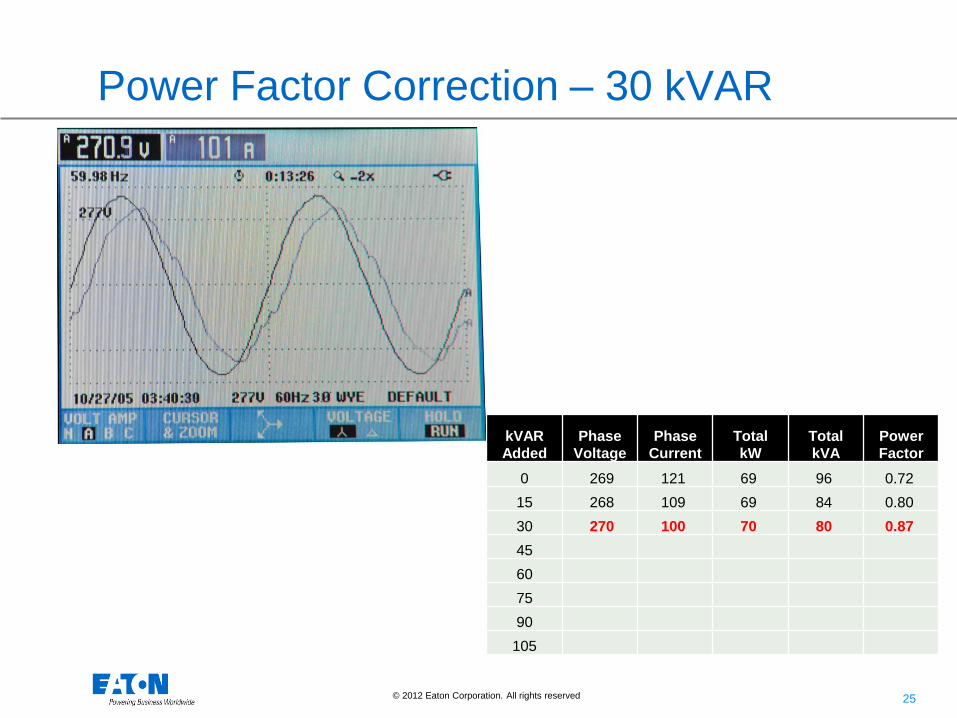
Power Factor Correction – 30 kVAR
kVAR
Added Phase
Voltage Phase
Current Total
kW Total
kVA Power
Factor
0 269 121 69 96 0.72
15 268 109 69 84 0.80
30 270 100 70 80 0.87
45
60
75
90
105
26 © 2012 Eaton Corporation. All rights reserved.
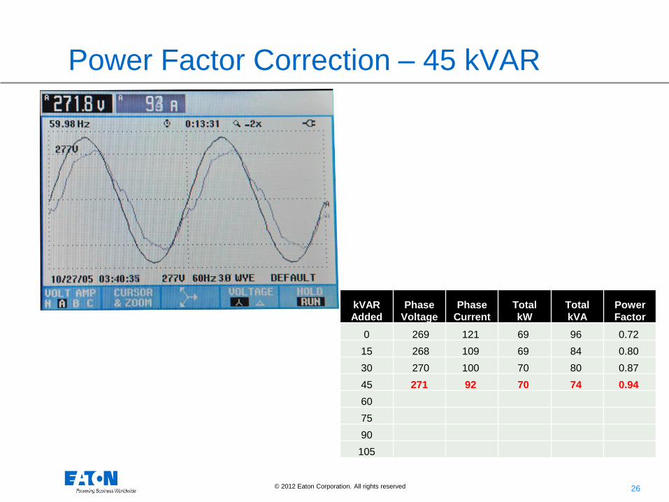
Power Factor Correction – 45 kVAR
kVAR
Added Phase
Voltage Phase
Current Total
kW Total
kVA Power
Factor
0 269 121 69 96 0.72
15 268 109 69 84 0.80
30 270 100 70 80 0.87
45 271 92 70 74 0.94
60
75
90
105

27 © 2012 Eaton Corporation. All rights reserved.
Power Factor Correction – 60 kVAR
kVAR
Added Phase
Voltage Phase
Current Total
kW Total
kVA Power
Factor
0 269 121 69 96 0.72
15 268 109 69 84 0.80
30 270 100 70 80 0.87
45 271 92 70 74 0.94
60 272 88 70 71 0.98
75
90
105

28 © 2012 Eaton Corporation. All rights reserved.
Power Factor Correction – 75 kVAR
kVAR
Added Phase
Voltage Phase
Current Total
kW Total
kVA Power
Factor
0 269 121 69 96 0.72
15 268 109 69 84 0.80
30 270 100 70 80 0.87
45 271 92 70 74 0.94
60 272 88 70 71 0.98
75 273 87 70 70 0.99
90
105

29 © 2012 Eaton Corporation. All rights reserved.
Power Factor Correction – 90 kVAR
kVAR
Added Phase
Voltage Phase
Current Total
kW Total
kVA Power
Factor
0 269 121 69 96 0.72
15 268 109 69 84 0.80
30 270 100 70 80 0.87
45 271 92 70 74 0.94
60 272 88 70 71 0.98
75 273 87 70 70 0.99
90 274 89 70 73 0.95 (1.05)
105

30 © 2012 Eaton Corporation. All rights reserved.
Power Factor Correction – 105 kVAR
kVAR
Added Phase
Voltage Phase
Current Total
kW Total
kVA Power
Factor
0 269 121 69 96 0.72
15 268 109 69 84 0.80
30 270 100 70 80 0.87
45 271 92 70 74 0.94
60 272 88 70 71 0.98
75 273 87 70 70 0.99
90 274 89 70 73 0.95 (1.05)
105 276 95 70 79 0.89 (1.11)

31 © 2012 Eaton Corporation. All rights reserved.
Power Factor Correction – No Caps
kVAR
Added Phase
Voltage Phase
Current Total
kW Total
kVA Power
Factor
0 269 121 69 96 0.72
15
30
45
60
75
90
105
32 © 2012 Eaton Corporation. All rights reserved.
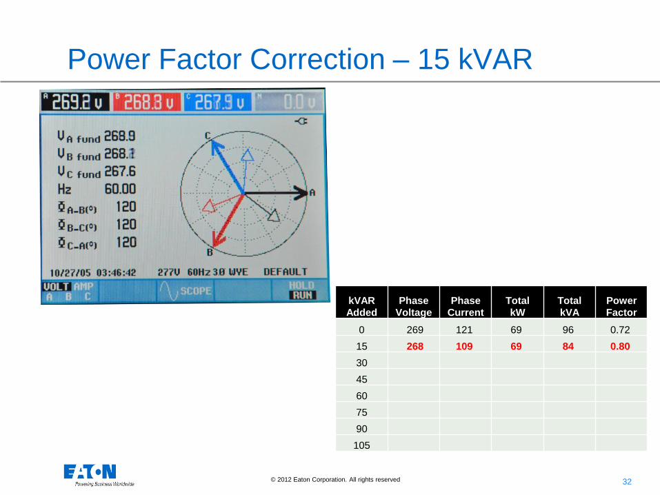
Power Factor Correction – 15 kVAR
kVAR
Added Phase
Voltage Phase
Current Total
kW Total
kVA Power
Factor
0 269 121 69 96 0.72
15 268 109 69 84 0.80
30
45
60
75
90
105

33 © 2012 Eaton Corporation. All rights reserved.
Power Factor Correction – 30 kVAR
kVAR
Added Phase
Voltage Phase
Current Total
kW Total
kVA Power
Factor
0 269 121 69 96 0.72
15 268 109 69 84 0.80
30 270 100 70 80 0.87
45
60
75
90
105

34 © 2012 Eaton Corporation. All rights reserved.
Power Factor Correction – 45 kVAR
kVAR
Added Phase
Voltage Phase
Current Total
kW Total
kVA Power
Factor
0 269 121 69 96 0.72
15 268 109 69 84 0.80
30 270 100 70 80 0.87
45 271 92 70 74 0.94
60
75
90
105
35 © 2012 Eaton Corporation. All rights reserved.
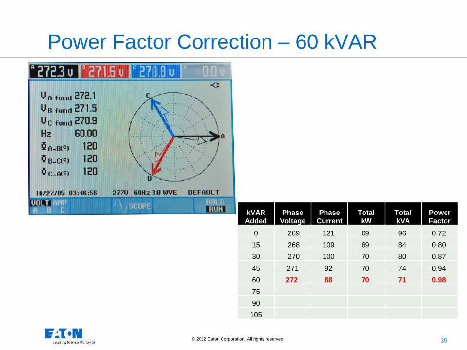
Power Factor Correction – 60 kVAR
kVAR
Added Phase
Voltage Phase
Current Total
kW Total
kVA Power
Factor
0 269 121 69 96 0.72
15 268 109 69 84 0.80
30 270 100 70 80 0.87
45 271 92 70 74 0.94
60 272 88 70 71 0.98
75
90
105

36 © 2012 Eaton Corporation. All rights reserved.
Power Factor Correction – 75 kVAR
kVAR
Added Phase
Voltage Phase
Current Total
kW Total
kVA Power
Factor
0 269 121 69 96 0.72
15 268 109 69 84 0.80
30 270 100 70 80 0.87
45 271 92 70 74 0.94
60 272 88 70 71 0.98
75 273 87 70 70 0.99
90
105

37 © 2012 Eaton Corporation. All rights reserved.
Power Factor Correction – 90 kVAR
kVAR
Added Phase
Voltage Phase
Current Total
kW Total
kVA Power
Factor
0 269 121 69 96 0.72
15 268 109 69 84 0.80
30 270 100 70 80 0.87
45 271 92 70 74 0.94
60 272 88 70 71 0.98
75 273 87 70 70 0.99
90 274 89 70 73 0.95 (1.05)
105

38 © 2012 Eaton Corporation. All rights reserved.
Power Factor Correction – 105 kVAR
kVAR
Added Phase
Voltage Phase
Current Total
kW Total
kVA Power
Factor
0 269 121 69 96 0.72
15 268 109 69 84 0.80
30 270 100 70 80 0.87
45 271 92 70 74 0.94
60 272 88 70 71 0.98
75 273 87 70 70 0.99
90 274 89 70 73 0.95 (1.05)
105 276 95 70 79 0.89 (1.11)

© 2007 Eaton Corporation. All rights reserved.
On-Site PFC Demonstration
Power Factor Demonstration Unit – Designed to show phase
displacement, system capacity increase, and dispel less than
reputable companies claiming 30-40% kW savings from capacitors!

40 © 2012 Eaton Corporation. All rights reserved.
Power Factor Defined – IEEE Emerald Book IEEE Std 1100-2005
• Power Factor (displacement):
• The displacement component of power factor
• The ratio of the active power of the fundamental
wave (in watts) to the apparent power of the
fundamental wave (in volt-amperes)
• Power Factor (total):
• The ratio of the total power input (in watts) to the
total volt-ampere input. NOTE: This definition includes the effect of harmonic
components of currents and voltage and the effect of phase
displacement between current and voltage.
kw
pf = --------
kva

41 © 2012 Eaton Corporation. All rights reserved. 41
Power Factor ‘True’ Equation
Reference: Dr. Mack Grady, University of Texas at Austin, Proc of the EPRI Power Quality Issues & Opportunities
Conference (PQA ‘93), San Diego, CA, November 1993.
For more info: http://users.ece.utexas.edu/~grady/POWERFAC.pdf
42 © 2012 Eaton Corporation. All rights reserved. 42
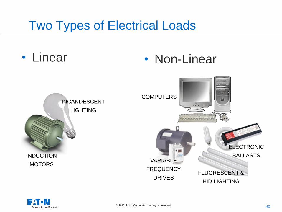
Two Types of Electrical Loads
• Linear • Non-Linear
INDUCTION
MOTORS
INCANDESCENT
LIGHTING
COMPUTERS
VARIABLE
FREQUENCY
DRIVES FLUORESCENT &
HID LIGHTING
ELECTRONIC
BALLASTS

43 © 2012 Eaton Corporation. All rights reserved. 43
Linear Loads Draw Power Linearly
• Electrical voltage and current “ebbs and flows” from plus to minus 60 times per second.
• Voltage and Current follow the same rhythm perfectly in a linear load
+
-
Voltage
Current
1/60T
H
SEC.

44 © 2012 Eaton Corporation. All rights reserved. 44
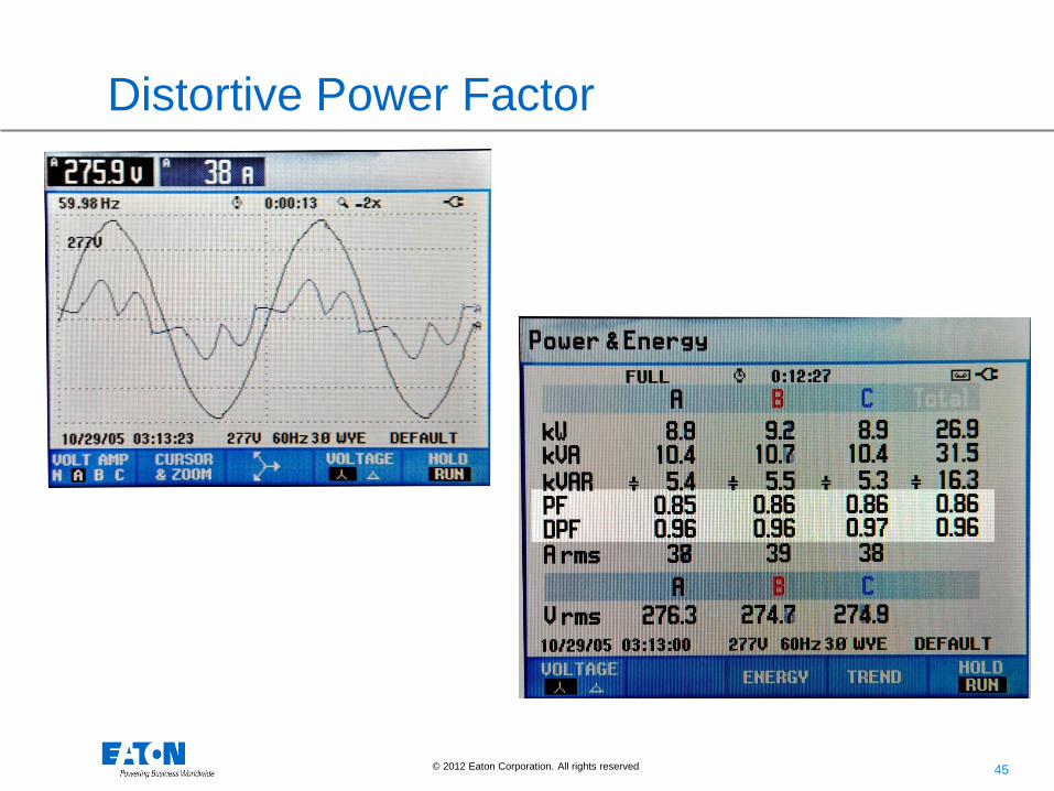
Non-Linear Loads Draw Power Unevenly
• Current is drawn in short “gulps” or pulses.
• Voltage and Current waveforms are irregular and don’t match – waveforms are said to be “DISTORTED”
• NON-LINEAR LOADS PRODUCE HARMONICS
• Harmonics cause mis-operation of equipment and WASTE ENERGY.
+
-
Voltage
Current
1/60T
H
SEC.
45 © 2012 Eaton Corporation. All rights reserved.
Distortive Power Factor

46
• Capacitors not only supply reactive power to the loads in an
electrical distribution system they also change the
resonance frequency of the system.
• Capacitors are also a “sink” for harmonic currents present in
a system (series resonance).
• When the resonance frequency of a system with PF
correction capacitors is close to the frequency of a harmonic
current generating load parallel resonance can occur.
Harmonic Resonance

47 © 2012 Eaton Corporation. All rights reserved.
Why talk about - Harmonic Resonance
The “Self Correcting”
Problem
- Blown Fuses
- Failed Capacitors
- Damaged Transformer

48
Parallel Resonance
Harmonic Current
Source XC XL
CL
CLEQUIVALENT
XjjX
XjjXX
)(
)(
Frequency Scan
1
10
100
1000
10000
100000
60 180 300 420 540 660 780 900 1020 1140 1260 1380 1500
Frequency in Hz
Imp
edan
ce in
Oh
ms
Equivalent Parallel Resonant Circuit Frequency Scan for Parallel Resonant Circuit
• The parallel combination of impedance is:
• Since XL and XC have opposite signs, the denominator can equal
zero if XL = XC. In reality, the only limiting factor is the difference in
resistance between the capacitor and reactor.

49
CAP
SCR
MVAR
MVAh
600 kVAR
1000 kVA
5.75%
480 V
Xs
200 HP
VSD
500 HP
Parallel Resonance

50 © 2012 Eaton Corporation. All rights reserved.
Parallel Resonance – the Problem
At 420Hz (the 7th harmonic) the
Z (impedance) of the circuit increases
from around 80 ohms to 10,000 ohms
125 times increase!
Subsequently, harmonic voltage
Increases 125 times!
Solution?
• Make sure you perform calculation
• Purchase Power Factor caps with detuned anti-resonance filter
• Use capacitor-less solutions (HCU & others)
Z ∞

51
The series combination of impedance is:
Since XL and XC have opposite signs, the summation can equal zero
if XL = XC. In reality, the only limiting factor is the difference in
resistance between the capacitor and reactor.
Equivalent Series Resonant Circuit Frequency Scan for Series Resonant Circuit
Harmonic Current
Source
XC
XL
CLEQUIVALENT XjjXX )(
Frequency Scan
0.1
1
10
100
1000
60 180 300 420 540 660 780 900 1020 1140 1260 1380 1500
Frequency in Hz
Imp
ed
an
ce in
Oh
ms
Series Resonance

52 © 2012 Eaton Corporation. All rights reserved. 52
H = NP+/-1
i.e. 6 Pulse Drive - 5, 7, 11, 13, 17, 19,…
Source Typical Harmonics*
6 Pulse Drive/Rectifier 5, 7, 11, 13, 17, 19…
12 Pulse Drive /Rectifier 11, 13, 23, 25…
18 Pulse Drive 17, 19, 35, 37…
Switch-Mode Power Supply 3, 5, 7, 9, 11, 13…
Fluorescent Lights 3, 5, 7, 9, 11, 13…
Arcing Devices 2, 3, 4, 5, 7...
Transformer Energization 2, 3, 4
Expected Harmonics

53 © 2012 Eaton Corporation. All rights reserved. 53
Harmonic Resonance - Solutions
1. Change the method of kvar compensation (harmonic
filter, active filter, etc.)
2. Change the size of the capacitor bank to over-
compensate or under-compensate for the required kvar
and live with the ramifications (i.e. overvoltage or PF
penalty).
Natural System frequency of oscillation typically at 5th to 13th harmonic

54 © 2012 Eaton Corporation. All rights reserved. 54
What type of PFC solution?
• Capacitors (standard/harmonically hardened)
• Harmonic Filters (Tuned or De-tuned)
• Active Filters
• LV or MV
• Fixed or Switched (contactor or thyristor)
• Active harmonic filter (PF and harmonic control)
Cost Capacitors Harmonic Filters Active Filters Hardened Capacitors
55 © 2012 Eaton Corporation. All rights reserved. 55
Capacitor Selection
Capacitor selection issues (besides size)
• Utility penalties
• Installed cost, payback of equipment, and NPV
• Load variability
• Voltage regulation
• Load requirements (Speed of changing PF)
• Harmonic resonance

57 © 2012 Eaton Corporation. All rights reserved.
Application Example – At the Load
R2 R1
Motor
Load
Resistive
Load
At a motor
Group of Motors
Group of Motors w/
harmonics
Variable Load
Variable System
Variable System w/
harmonics
Rapidly changing
load
Electronic VAR
Injector
MV at a motor
MV variable load
Eaton Unipump Advantages • Auto-regulating, comes on and off with load
• Capacitor matched with load – reduces concern of overcorrection
• Relatively small in size – easy to locate, no additional distribution equipment required
When to Use • Facility load fluctuates
• Many anticipated changes to plant system and
loads
58 © 2012 Eaton Corporation. All rights reserved.
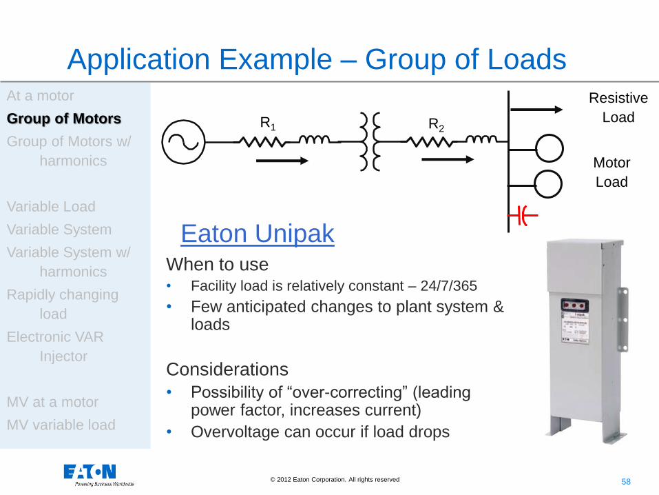
Application Example – Group of Loads
R2 R1
Motor
Load
Resistive
Load
At a motor
Group of Motors
Group of Motors w/
harmonics
Variable Load
Variable System
Variable System w/
harmonics
Rapidly changing
load
Electronic VAR
Injector
MV at a motor
MV variable load
Eaton Unipak When to use • Facility load is relatively constant – 24/7/365
• Few anticipated changes to plant system & loads
Considerations
• Possibility of “over-correcting” (leading power factor, increases current)
• Overvoltage can occur if load drops

59 © 2012 Eaton Corporation. All rights reserved.
Application Example – Group of Harmonic Loads
R2 R1
Harmonic
Motor Load
Resistive
Load
At a motor
Group of Motors
Group of Motors w/
harmonics
Variable Load
Variable System
Variable System w/
harmonics
Rapidly changing
load
Electronic VAR
Injector
MV at a motor
MV variable load
Eaton Unipak Filter When to use • Facility load is relatively constant – 24/7/365
• Few anticipated changes to plant system & loads
• Capacitors protected from harmonics through the use of a detuned, anti-resonance filter / reactors
Considerations
• Possibility of “over-correcting” (leading power factor, increases current)
• Overvoltage can occur if load drops
60 © 2012 Eaton Corporation. All rights reserved.
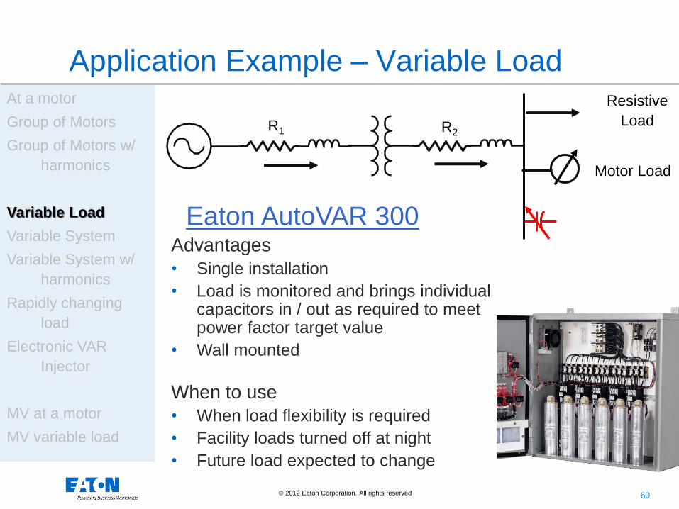
Application Example – Variable Load
R2 R1
Motor Load
Resistive
Load
At a motor
Group of Motors
Group of Motors w/
harmonics
Variable Load
Variable System
Variable System w/
harmonics
Rapidly changing
load
Electronic VAR
Injector
MV at a motor
MV variable load
Eaton AutoVAR 300 Advantages
• Single installation
• Load is monitored and brings individual capacitors in / out as required to meet power factor target value
• Wall mounted
When to use
• When load flexibility is required
• Facility loads turned off at night
• Future load expected to change

61 © 2012 Eaton Corporation. All rights reserved.
Application Example – Variable System
R2 R1
Motor Load
Resistive
Load
At a motor
Group of Motors
Group of Motors w/
harmonics
Variable Load
Variable System
Variable System w/
harmonics
Rapidly changing
load
Electronic VAR
Injector
MV at a motor
MV variable load
Eaton AutoVAR 600 Advantages
• Single installation
• System is monitored and brings individual capacitors in / out as required to meet power factor target value
• Floor mount
When to use
• When system flexibility is required
• Facility loads turned off at night
• Future load expected to change

62 © 2012 Eaton Corporation. All rights reserved.
Application Example – Variable System with harmonics
R2 R1
Harmonic
Motor Load
Resistive
Load
At a motor
Group of Motors
Group of Motors w/
harmonics
Variable Load
Variable System
Variable System w/
harmonics
Rapidly changing
load
Electronic VAR
Injector
MV at a motor
MV variable load
Eaton AutoVAR 600 Filter Advantages
• Single floor mount installation
• System is monitored and brings individual capacitors in / out as required to meet power factor target value
• Floor mount
When to use
• When system flexibility is required
• Facility loads turned off at night
• Future load expected to change

63 © 2012 Eaton Corporation. All rights reserved.
Application Example – Rapidly Changing Load
R2 R1
Rapid
changing
Harmonic
Motor Load
Resistive
Load
At a motor
Group of Motors
Group of Motors w/
harmonics
Variable Load
Variable System
Variable System w/
harmonics
Rapidly changing
load
Electronic VAR
Injector
MV at a motor
MV variable load
Eaton Fast Transient Free Advantages
• Switches at zero-crossing – no transients
• Can correct Power Factor within: FTA Model – 3 to 4 s FTE Model – 5 to 20 ms
• Includes detuned, anti-resonance filtering
When to use
• Rock crushing or other rapidly changing loads that require power factor correction

64 © 2012 Eaton Corporation. All rights reserved.
Application Example – Electronic VAR Injector
R2 R1
Rapid
changing
Harmonic
Motor Load
Resistive
Load
At a motor
Group of Motors
Group of Motors w/
harmonics
Variable Load
Variable System
Variable System w/
harmonics
Rapidly changing
load
Electronic VAR
Injector
MV at a motor
MV variable load
Electronic VAR Injector Advantages
• Power electronics – no capacitors
• Provide VARs in non-standard harmonic environment
• 2 cycle response
When to use
• Most demanding of all electrical environments (208-480V, 45 to 65 Hz)

65 © 2012 Eaton Corporation. All rights reserved.
Application Example – Medium Voltage at Motor
R2
Motor Load
Resistive
Load
At a motor
Group of Motors
Group of Motors w/
harmonics
Variable Load
Variable System
Variable System w/
harmonics
Rapidly changing
load
Electronic VAR
Injector
MV at a motor
MV variable load
Eaton MV UniVAR & MV
Advantages
• Designed for industrial and commercial power systems with their own substations
• UniVAR XV: 2.4kV to 4.8kV
• UniVAR MV: 6.6kV to 13.8kV
• Available from 25 kVAR to 900 kVAR
Motor Load

66 © 2012 Eaton Corporation. All rights reserved.
Application Example – Medium Voltage Variable load
R2
Motor Load
Resistive
Load
At a motor
Group of Motors
Group of Motors w/
harmonics
Variable Load
Variable System
Variable System w/
harmonics
Rapidly changing
load
Electronic VAR
Injector
MV at a motor
MV variable load
Metal-Enclosed MV
Advantages
• Built in detuning, anti-resonance filtering to protect the capacitors
• Up to 15 MVAR of compensation
• Top of Bottom Cable Entry
• Up to 12 automatic switched capacitor/reactor stages

67 © 2012 Eaton Corporation. All rights reserved. 67
Power Quality Experience Center and Lab
• Overview of Lab and Capabilities
• Purpose
• To demonstrate and Test PQ
Problems and Solutions
• Power Quality solutions, especially
harmonic solutions, are difficult to
understand
• Demystify solutions – mis-information and confusion regarding PQ and
energy savings
• Equipment (Harmonic Related)
• 18 Pulse Drives
• HMT’s
• Active Filters
• Broadband Filters
• Link:http://www.eaton.com/EatonCom/Markets/Electrical/ServicesSupport/Experi
ence/index.htm – Simply search on Google for Eaton Experience Center
• Passive (Fixed) Filters
• Passive (Switched) Filters
• Active Rectifier (UPS)
• Reactors

68 © 2012 Eaton Corporation. All rights reserved. 68
Eaton Power Factor Correction ToolTM - Resonance

69 © 2012 Eaton Corporation. All rights reserved.
PFC Tools – PFC Selection Chart
70 © 2012 Eaton Corporation. All rights reserved.
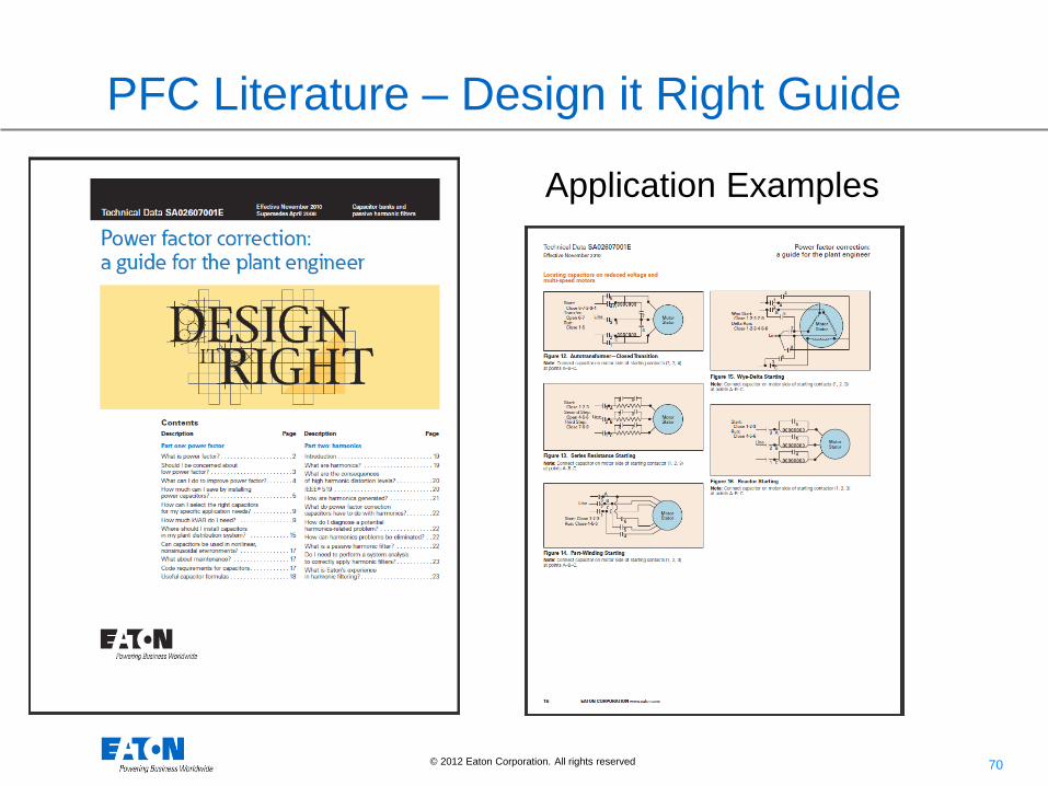
PFC Literature – Design it Right Guide
Application Examples

71 © 2012 Eaton Corporation. All rights reserved.
PFC Literature – Design it Right Guide
Sizing Charts
72 © 2012 Eaton Corporation. All rights reserved.
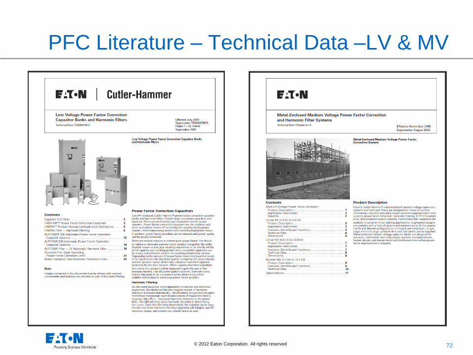
PFC Literature – Technical Data –LV & MV

73 © 2012 Eaton Corporation. All rights reserved.
PFC Literature – Customer Survey Sheet
74 © 2012 Eaton Corporation. All rights reserved.
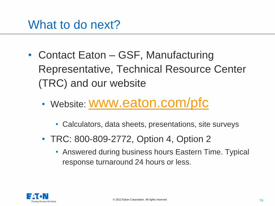
What to do next?
• Contact Eaton – GSF, Manufacturing
Representative, Technical Resource Center
(TRC) and our website
• Website: www.eaton.com/pfc
• Calculators, data sheets, presentations, site surveys
• TRC: 800-809-2772, Option 4, Option 2
• Answered during business hours Eastern Time. Typical
response turnaround 24 hours or less.

© 2012 Eaton Corporation. All rights reserved.
The Hidden Threat Quick introduction to Surge Protection

76 © 2012 Eaton Corporation. All rights reserved.
Voltage Transients (Surge)
Definition
A high rising voltage condition which lasts 2 ms or less and can produce up to 20 kV!

77 © 2012 Eaton Corporation. All rights reserved.
What is the Threat?
• Equipment damage
• Insulation breakdown
• Premature aging
• Process interruption
• Data loss

78 © 2012 Eaton Corporation. All rights reserved.
What are the Causes?
20% External
• Lightning
• Capacitor
switching
• Utility load
switching
80% Internal
• Load switching
• Short circuits
• Manufacturing
Equipment
• VS Drives

© 2012 Eaton Corporation. All rights reserved.
SPD Design Design Tips

80 © 2012 Eaton Corporation. All rights reserved.
Independent tests confirm better performance with integrated SPDs
Direct Bus
Connected
Best Protection
Wired
Connection
Better than side
mount.
Side Mount
Good let-though
if leads are short.
Good Better Best

81 © 2012 Eaton Corporation. All rights reserved.
IEEE C1 (6000V, 3000A) Waveform
Ad
dit
ion
al L
et
Th
rou
gh
Vo
lta
ge
(Ad
dit
ion
al to
de
vic
e L
et
Th
rou
gh
)
Performance/Application - Affect of Lead Length on Let-through Voltage
0
100
200
300
400
500
600
700
800
900
3 Feet Loose Wire 3 Feet Twisted Wire 1 Foot Twisted Wire
14 AWG
10 AWG
4 AWG
82 © 2012 Eaton Corporation. All rights reserved.
Nameplate Data - Peak surge current rating
• The peak surge current is
a predictor of how long an
SPD will last in a given
environment
• The higher the kA, the
longer the life of the MOVs
• Similar to the tread on a
tire
• The thicker the tread, the
longer the tire will last

83 © 2012 Eaton Corporation. All rights reserved.
IEEE Emerald Book facts
20 feet of conduit
Panelboards are available that contain integrally
mounted SPDs that minimize the length of the SPD
conductors, thus optimizing the effectiveness of
the device.
“Why is my SPD Not
Protecting Me?”

84 © 2012 Eaton Corporation. All rights reserved.
Biggest News in Surge Protection
2014 NEC Article 700.8
requires surge protection for
emergency circuits. Eaton has
produced Sales Aid
SA158003EN to describe this
code change and impact. The
document is available on
literature fulfillment and the
website.

85 © 2012 Eaton Corporation. All rights reserved.