
Power Estimation for a Two Seater Helicopter
12
Journal of Transport System Engineering 1 : 1 (2014), 55-66 55 Power Estimation for a Two Seater Helicopter Mohammad Nazri Mohd Jaafar, a,* Mohd Idham Mohd Nayan, a M.S.A. Ishak, b a Department of Aeronautical Engineering, Faculty of Mechanical Engineering, Universiti Teknologi Malaysia, 81310 UTM Skudai, Johor, Malaysia. b School of Manufacturing Engineering, Universiti Malaysia Perlis, PO Box 77, Pejabat Pos Besar, 01000 Kangar, Perlis, Malaysia. *Corresponding author: [email protected] Abstract The paper describes the methods to estimate power required by two seater helicopter at three flight conditions: hovering, vertical climbing and forward flight. Factors that affect the power required by the helicopter include induced velocity along the rotor blade, various altitudes, horizontal force due to the fuselage and others are discussed in this paper. Methods analyzed in this study to estimate the power are momentum method, blade element method and combined method. The initial specification of the helicopter was done by studying the present helicopter configuration in the market. All related data were then plotted against gross weight. The study on weight estimation was done according to the Prouty method and based on some assumptions. The helicopter specification as studied in this paper was found closely similar to the specification of existing helicopter in the market. Keywords: Power estimation, gross weight, develop programming, preliminary helicopter design 1. INTRODUCTION Helicopter is a useful and popular air vehicle nowadays. There are many types of helicopter in present market, which can be divided into light and heavy type [1]. An example of light helicopter (capacity of 2 crews) is Robinson R22, while the heavy types (capacity of 12 crews) are mostly for a military purpose such as Black Hawk [2]. By definition, helicopter is an aircraft which is lifted and propelled by one or more horizontal rotors; each with two or more rotor blades [3]. Helicopters can also be classified as rotary-wing aircraft to distinguish them from fixed-wing aircraft [4]. Rotor blade gains the power to rotate from the helicopter propulsion system. There are two types of engine available in the helicopter market, piston engine and turbo-shaft engine [5]. The engine is chosen based on power available, performance required, fuel consumption and other factors. This research focused on two-seater helicopter to estimate the power and weight for this type of helicopter. 2.PARAMETRIC STUDY 2.1 Preliminary Sizing Sizing is the first and an important stage in helicopter preliminary design process. Design trends analysis is a well-known technique, in which flying configurations are analysed in order to conclude or identify a trend which is common to many configurations. Therefore, it may represent physical constrains which are not clear and evident at the early stages [6]. Design trends analysis is useful for the sizing stage in its broad sense: geometrical sizing and preliminary sizing of performance, power required and other parameters [7]. In this study, for the initial estimate of sizing, the historical surveys of similar helicopter were JTSE
Transcript of Power Estimation for a Two Seater Helicopter

Journal of Transport System Engineering 1 : 1 (2014), 55-66
55
Power Estimation for a Two Seater
Helicopter Mohammad Nazri Mohd Jaafar,
a,* Mohd Idham Mohd Nayan,
a M.S.A. Ishak,
b
aDepartment of Aeronautical Engineering, Faculty of Mechanical Engineering, Universiti Teknologi Malaysia, 81310 UTM
Skudai, Johor, Malaysia. bSchool of Manufacturing Engineering, Universiti Malaysia Perlis, PO Box 77, Pejabat Pos Besar,
01000 Kangar, Perlis, Malaysia.
*Corresponding author: [email protected]
Abstract
The paper describes the methods to estimate power required by two seater helicopter at three flight conditions:
hovering, vertical climbing and forward flight. Factors that affect the power required by the helicopter include
induced velocity along the rotor blade, various altitudes, horizontal force due to the fuselage and others are
discussed in this paper. Methods analyzed in this study to estimate the power are momentum method, blade
element method and combined method. The initial specification of the helicopter was done by studying the
present helicopter configuration in the market. All related data were then plotted against gross weight. The study
on weight estimation was done according to the Prouty method and based on some assumptions. The helicopter
specification as studied in this paper was found closely similar to the specification of existing helicopter in the
market.
Keywords: Power estimation, gross weight, develop programming, preliminary helicopter design
1. INTRODUCTION
Helicopter is a useful and popular air vehicle
nowadays. There are many types of helicopter in
present market, which can be divided into light and
heavy type [1]. An example of light helicopter
(capacity of 2 crews) is Robinson R22, while the
heavy types (capacity of 12 crews) are mostly for a
military purpose such as Black Hawk [2]. By
definition, helicopter is an aircraft which is lifted
and propelled by one or more horizontal rotors;
each with two or more rotor blades [3]. Helicopters
can also be classified as rotary-wing aircraft to
distinguish them from fixed-wing aircraft [4]. Rotor
blade gains the power to rotate from the helicopter
propulsion system. There are two types of engine
available in the helicopter market, piston engine and
turbo-shaft engine [5]. The engine is chosen based
on power available, performance required, fuel
consumption and other factors. This research
focused on two-seater helicopter to estimate the
power and weight for this type of helicopter.
2.PARAMETRIC STUDY
2.1 Preliminary Sizing
Sizing is the first and an important stage in
helicopter preliminary design process. Design
trends analysis is a well-known technique, in which
flying configurations are analysed in order to
conclude or identify a trend which is common to
many configurations. Therefore, it may represent
physical constrains which are not clear and evident
at the early stages [6]. Design trends analysis is
useful for the sizing stage in its broad sense:
geometrical sizing and preliminary sizing of
performance, power required and other parameters
[7].
In this study, for the initial estimate of sizing, the
historical surveys of similar helicopter were
JTSE

Journal of Transport System Engineering 1 : 1 (2014), 55-66
56
searched. Then, all the data were tabulated to
compare the specifications of all helicopters chosen.
This is important to obtain early ideas on the initial
configuration of the intended design for the
helicopter. Information obtained from the data was
then used to determine the new specification of the
helicopter. Below is the list of the helicopters that
were studied. All the specifications are the latest
configuration obtained from the internet.
1. Enstrom F28a
2. Enstrom F28f
3. Brantly B2b
4. Bell 47j
5. Baby Elle
6. Robinson R22
7. Bongo
8. Schweizer 300cb
9. Th-28 Eagle
10. Na 42 Barracuda
11. Mosquito
12. Exec 162f
13. Dragon Fly
Based on the data gathered, the most suitable
helicopter as base two-seat helicopters is Robinson
R22 [8]. Moreover, R22 is the most popular two-
seater helicopter as training helicopter and it is also
available in Malaysia. Thus, this helicopter had
been chosen as a model for reference in the
preliminary design for the proposed helicopter
specification.
Based on the gathered data, graphs of the main
parameters of the helicopter specifications were
plotted as shown in Figure 1 and 2. The following
trade studies included parameters such as Tail Rotor
Diameter, Vcruise, Fuselage Length and Height, etc.
The proposed specification for the helicopter is
shown in Table 1.
Figure 1. Disk Loading Vs Take Off Weight
Figure 2. Disk Area Vs Take Off Weight

Journal of Transport System Engineering 1 : 1 (2014), 55-66
57
Table 1. Specification for Proposed Helicopter
GENERAL
Type of aircraft Light Helicopter
Regulation FAR Part 27
No of seat 2
No of engine 1
Function
Pilot Trainer,
Recreation,
Surveillance
ENGINE CONFIGURATION
Type Piston engine
Model Lycoming O-320-
B2C
Thrust Power 131 hp
Fuel capacity 19.2 gal
WEIGHT
Empty, We 793.9 lb
Gross, Wo 1364.9 lb
Fuel, Wf 131 lb
Crew, Wcrew
340 lb
Empty
Gross 0.58
MAIN & TAIL ROTOR
Blade shape (main) Symmetrical
Airfoil type NACA 0015
Disk loading 2.784 lb/ft2
Blade shape (tail) Symmetrical
Airfoil type NACA 0015
EXTERNAL DIMENSION
Main rotor diameter 29.48 ft
Tail rotor diameter 2.78 ft
Length overall 34.65 ft
Height overall 12.14 ft
PERFORMANCE
Cruise velocity, Vcr 529.13 ft/s
Velocity never exceed, VNE 608.47 ft/s
Service ceiling 10861.94 ft
Range 1336.34 ft
Endurance 2.91 hours
2.2 Weight Estimation and Weight Balance
(Based On Robinson R22 Beta)
There are two ways to estimate helicopter weight.
The first method is by observing the trend of the
present helicopter in the market. From the graphs
shown before (Figure 1 and Figure 2), the main
parameter to obtain other parameters is the gross
weight or maximum take-off weight.
This important parameter can be obtained from
these two graphs as an initial estimate. This is
called the parametric study for one to start the
design of a new helicopter. The second method is
by referring to the Prouty Weight Estimation [9].
Table 2 shows the data for weight estimation and
Table 3 shows the data for weight balance.
2.3 Main Rotor Design
The main rotor is the most important component of
the helicopters. Proper design of the rotor is critical
to meeting the performance specifications for the
helicopter as a whole [10]. Below are the required
parameters to design the main rotor, which are
summarized in Table 4:
a) Helicopter Weight
b) Induced velocity
c) Number of Blades
d) Inflow Ratio
e) Airfoil type
f) Optimum Angle for the particular
airfoil of ( Cl /Cd)
g) Zero lift drag coefficient
Journal of Transport System Engineering 1 : 1 (2014), 55-66
58
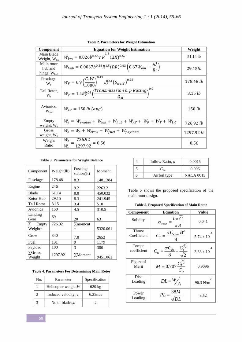
Table 2. Parameters for Weight Estimation
Component Equation for Weight Estimation Weight
Main Blade
Weight, Wbm
( ) 51.14 lb
Main rotor
hub and
hinge, Whub
( ) (
)
Fuselage,
WF (
)
( )
Tail Rotor,
Wt
(
)
Avionics,
Wav
( )
Empty
weight, We
Gross
weight, Wo
Weight
Ratio
Table 3. Parameters for Weight Balance
Component Weight(lb) Fuselage
station(ft) Moment
Fuselage 178.48 8.3 1481.384
Engine 246 9.2 2263.2
Blade 51.14 8.8 450.032
Rotor Hub 29.15 8.3 241.945
Tail Rotor 3.15 3.4 510
Avionics 150 4.5 310.5
Landing
Gear 69
20 63
∑ Empty
Weight=
726.92
∑moment
= 5320.061
Crew 340 7.8 2652
Fuel 131 9 1179
Payload 100 3 300
∑Gross
Weight 1297.92 ∑Moment
9451.061
Table 4. Parameters For Determining Main Rotor
No. Parameter Specification
1 Helicopter weight,W 620 kg
2 Induced velocity, vi 6.25m/s
3 No of blades,b 2
4 Inflow Ratio, μ 0.0015
5 Cdo 0.006
6 Airfoil type NACA 0015
Table 5 shows the proposed specification of the
main rotor design.
Table 5. Proposed Specification of Main Rotor
Component Equation Value
Solidity
rotor
b C
R
0.041
Thrust
Coefficient
2
max
4T
C BC
5.74 x 10
-3
Torque
coefficient
32
8 2
do TQ
C CC
3.38 x 10
-4
Figure of
Merit
32
0.707 T
Q
CM
C 0.9096
Disc
Loading
WDLA
96.3 N/m2
Power
Loading
38MPL
DL 3.52

Journal of Transport System Engineering 1 : 1 (2014), 55-66
59
3.DEVELOPED SOFTWARE FROM MATLAB
The power required by each flight condition
(hovering, vertical climbing and forward flight) has
been estimated using the software developed using
Matlab 7.0. This software can give a quick solution
to the analysis by just keying the values in the
software [11]. The data required from the
developed software can be used to determine the
specific power required for each flight condition.
3.1 Developed Software Using Matlab
To use the software, the user only needs to key in
the data into the empty box in the software and by
clicking the calculate button, the parameters such as
powers and coefficient for each type flight
condition can be obtained easily. The data obtained
from the software can be used to calculate the
specific value for the analysis. Figures 3, 4 and 5
show the interface of the software.
Figure 3. Interface for Estimating Required Power for Hovering

Journal of Transport System Engineering 1 : 1 (2014), 55-66
60
Figure 4. Interface for Estimating Required Power for Vertical Climbing
Figure 5. Interface for Estimating Required Power for Forward Flight

Journal of Transport System Engineering 1 : 1 (2014), 55-66
61
4.RESULTS AND DISCUSSION
The analysis focused on determining two main
parameters, i.e. to identify the weight of the
components and to estimate the power required by
the helicopter for hovering, vertical climbing and
forward flight. The results of this study can provide
guide to estimate power for two seater helicopter.
4.1 Weight Estimation
For preliminary design, Prouty Weight Estimation
method had been used to do the analysis for weight
estimation. Although weight estimation for the
proposed helicopter can also obtained through the
trend analysis graphs, the Prouty Method would
give the best estimation. The steps to obtain weight
estimation have been explained in the parametric
study. From the analysis, the gross weight of the
proposed helicopter was 1297.2 lbs and its empty
weight was 726.92 lbs. Other weights that had been
considered in this analysis were weights of theMain
Blade, Main rotor hub and hinge, Fuselage, Tail
Rotor, and Avionics.
From the analysis, it was found that the gross
weight of the proposed helicopter with the other
two-seat helicopter in the market only had slight
difference, even after weight balancing for each
component had been allocated to certain places on
the helicopter. From the calculation, the center of
gravity for takeoff was 7.28 ft for gross weight and
was 7.42 ft for empty weight, both determined from
the helicopter nose.
4.2 Trend Data Analysis
From the parameter study, graph of each parameter
had been plotted. The analysis included the study
on trend, sequence and economical trend of
helicopter in the market. The graphs indicate the
portion that influence weight of the helicopter to
estimate the take off weight. Other parameters
regarding this initial estimation were also obtained.
Lastly the criteria for purposed helicopter obtained
through out this process.
4.3 Power Analysis
The results are represented in graphs to describe the
power required by the main rotor for each flight
condition of hovering, vertical climbing and
forward flight. Different method is used to estimate
the power for each flight condition. It is important
to determine the total power required for the
proposed helicopter to estimate the overall
performance, known as power analysis, so that the
helicopter will have enough thrust to fly. The power
analysis was conducted for hovering, vertical
climbing and forward flight conditions.
4.3.1 Hovering Condition
In this study, four graphs representing the power
analysis for hovering condition had been plotted, as
follows:
1. Thrust Coefficient Vs Collective Pitch
2. Downwash Coefficient Vs Collective Pitch
3. Power Coefficient Vs Collective Pitch
4. Power Vs Altitude
The results were obtained using the momentum
method, blade element method and combined
method, as explained in the literature review. Each
result (graph) shows the relation between the
parameter and power required by the proposed
helicopter to hover. The graphs also indicate the
factors that affect the total power required in
hovering condition. Total power required is defined
as the sum of profile power and induced power.
Figure 6 shows the results of thrust coefficient
versus collective pitch. The graph indicates a
quadratic relation between thrust coefficient and
collective pitch. It can also be seen that the thrust
coefficient increased quadratically with collective
pitch. There are other factors that caused the
increasing value, which were rotor solidity, angle of
attack and downwash coefficient. Relating these
parameters with power required clearly shows that
for a given thrust and collective pitch, there was
also an increment in total power required by the
proposed helicopter.

Journal of Transport System Engineering 1 : 1 (2014), 55-66
62
Figure 6. Plot of the Thrust Coefficient at various Collective Pitch
Figure 7. Plot of Downwash Coefficient at various Collective Pitch
Figure 7 shows the relation between downwash
coefficient and collective pitch. The downwash
coefficient increased gradually with collective
pitch. This was because the thrust coefficient
increased in a similar manner. Both parameters
were related to estimate minimal power required by
the proposed helicopter to fly. The figure also
indicates that there was a value for zero collective
pitch. It was because when there was no collective
pitch input from the cockpit, due to the effect of the
induced velocity due to rotating rotor to the blade.
Figure 8 shows the relation between power
coefficient and collective pitch. The value for
power coefficient also increased gradually with
collective pitch. The increment of power coefficient
depends on the induced velocity in hover condition.
For this analysis, it was assumed that the
inductionwas constant along the blade. This theory
does not apply to the real condition because
induced power varies continuously along the blade.
For an increased collective pitch given by the pilot,
the power coefficient would also increase, followed
by increment of thrust coefficient.
Journal of Transport System Engineering 1 : 1 (2014), 55-66
63
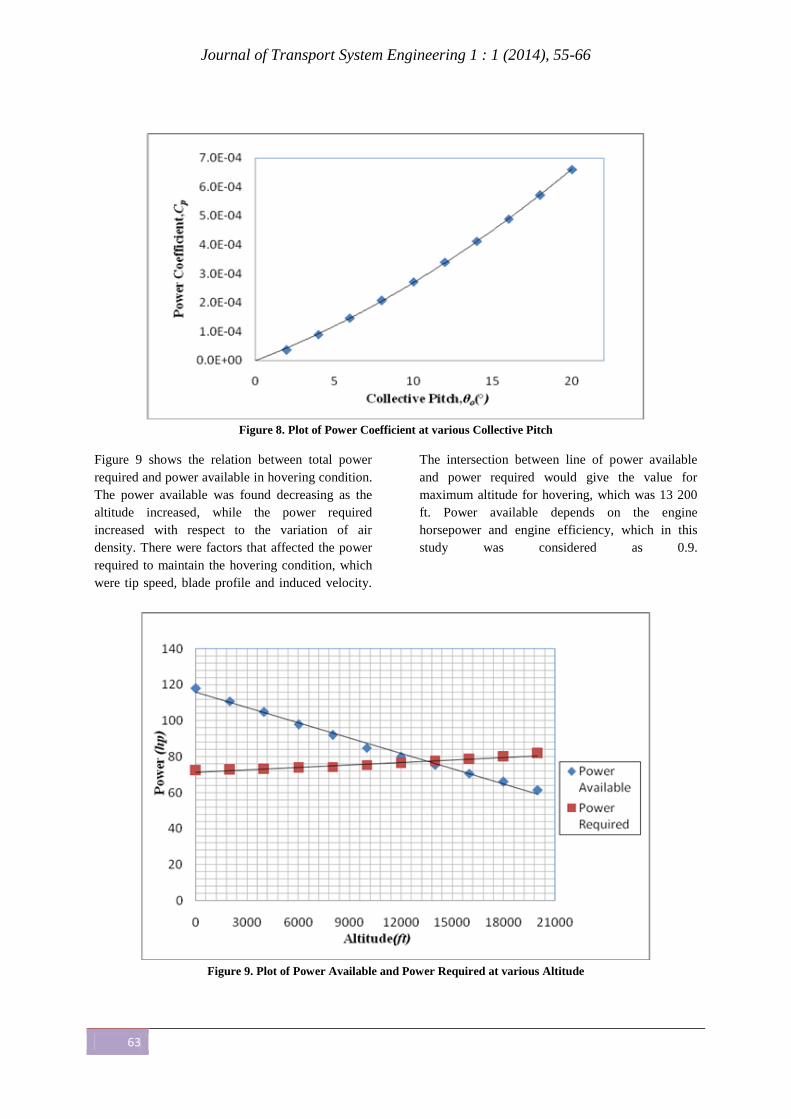
Figure 8. Plot of Power Coefficient at various Collective Pitch
Figure 9 shows the relation between total power
required and power available in hovering condition.
The power available was found decreasing as the
altitude increased, while the power required
increased with respect to the variation of air
density. There were factors that affected the power
required to maintain the hovering condition, which
were tip speed, blade profile and induced velocity.
The intersection between line of power available
and power required would give the value for
maximum altitude for hovering, which was 13 200
ft. Power available depends on the engine
horsepower and engine efficiency, which in this
study was considered as 0.9.
Figure 9. Plot of Power Available and Power Required at various Altitude
Journal of Transport System Engineering 1 : 1 (2014), 55-66
64
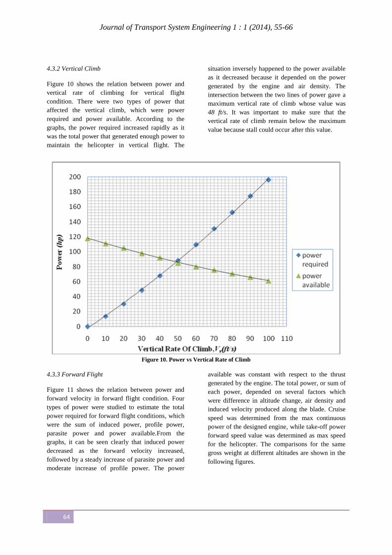
4.3.2 Vertical Climb
Figure 10 shows the relation between power and
vertical rate of climbing for vertical flight
condition. There were two types of power that
affected the vertical climb, which were power
required and power available. According to the
graphs, the power required increased rapidly as it
was the total power that generated enough power to
maintain the helicopter in vertical flight. The
situation inversely happened to the power available
as it decreased because it depended on the power
generated by the engine and air density. The
intersection between the two lines of power gave a
maximum vertical rate of climb whose value was
48 ft/s. It was important to make sure that the
vertical rate of climb remain below the maximum
value because stall could occur after this value.
Figure 10. Power vs Vertical Rate of Climb
4.3.3 Forward Flight
Figure 11 shows the relation between power and
forward velocity in forward flight condition. Four
types of power were studied to estimate the total
power required for forward flight conditions, which
were the sum of induced power, profile power,
parasite power and power available.From the
graphs, it can be seen clearly that induced power
decreased as the forward velocity increased,
followed by a steady increase of parasite power and
moderate increase of profile power. The power
available was constant with respect to the thrust
generated by the engine. The total power, or sum of
each power, depended on several factors which
were difference in altitude change, air density and
induced velocity produced along the blade. Cruise
speed was determined from the max continuous
power of the designed engine, while take-off power
forward speed value was determined as max speed
for the helicopter. The comparisons for the same
gross weight at different altitudes are shown in the
following figures.

Journal of Transport System Engineering 1 : 1 (2014), 55-66
65
Figure 11. Power vs Forward Velocity
Figure 12. Comparison of Power at Different Altitude
For the proposed design, the cruise speed was
defined to be the speed at which the power required
is equal to the maximum continuous power that
could be obtained from the engine. Although not
exactly equal to the speed for maximum range, it
was found that the cruising and maximum-range
speeds were close enough to each other that almost
the same range was achieved with either, as
indicated by the specific range trends shown in
Figure 12. For most helicopters, the power required
to hover is greater than the power required to
cruise. Therefore, the transmission and
consequently the engine is sized by a maximum
continuous power requirement rather than by a
transient (take-off) rating requirement.
Cruise power required is maximum at sea level,
according to ISA conditions. With increase in
altitude or in air temperature, air density is reduced,
leading to a reduction in parasite drag and in the
power required to fly at a given speed. However,
since the power deliverable by the engine in reality

Journal of Transport System Engineering 1 : 1 (2014), 55-66
66
decreases with density, the maximum continuous
power available to the helicopter also decreases.
Note that the available power at any density altitude
also depends on how much the engine is de-rated
from its maximum uninstalled rating.
From Figure 12, the following values are obtained
for the proposed helicopter:
1. Maximum Velocity, Vmax =212 ft/s
2. Endurance Velocity, Ven =80 ft/s
3. Range Velocity, VR =140 ft/s
5. CONCLUSION
As there are many light helicopters present in the
market, the main factors for best selection are the
design and purpose of mission. This paper has
briefly explained power estimation method for light
two-seat helicopter. The proposed design follows
closely the actual specification of present helicopter
in the market for light helicopter type. As for the
gross and empty weight analysis, the obtained
values had been compared to those of present
helicopter, which are in an ideal range, in which
this helicopter has a gross weight of about1365 lb.
Although there are many assumptions that have
been made in the analysis for estimating the power
required by the helicopter in various conditions, the
result can provide a general insight on power
estimation required for future light helicopter.
REFERENCES
[1] Shariff A. (2006). Teknologi Helikopter. UTM
Skudai.
[2] Elfanap Rees. (1986). World Military Helicopter.
United Kingdom: Jane Publishing Company
Limited.
[3] Watkinson, J. (2004). The Art of Helicopter. 1st
Edition. Burlington: Elsevier Butterworth.
[4] Bramwell, A.R.S. (1976). Helicopter Dynamics.
Edward Arnold (Publishers) Ltd.
[5] Donald, M.L. (1984). Helicopter Performance.
America: Matrix Publishers, Inc.
[6] Rand, O. and Khromov, V. (2004). Helicopter
Sizing by Statistics. Journal of the American
Helicopter Society, 49 (3), pp. 300–317
[7] Leishman, J. G. (2001). Principles of Helicopter
Aerodynamics. Cambridge University Press.
[8] McGraw-Hill (1995). Helicopter Pilot Reports.
America. McGraw-Hill Companies Inc.
[9] Prouty, R.W. (1995). Helicopter Performance,
Stability, and Control. Krieger Publishing Company.
1995.
[10] Peters & Chen (1982). Momentum Theory, Dynamic
Inflow, and the Vortex Ring State. JAHS 27-3.
[11] Stephen, J. C. (2002). Matlab Programming for
Engineers. USA: Wadsworth Group.


![State Estimation an Autonomous Helicopter Using Kalman ... paper/c38_www... · State Estimation of an Autonomous Helicopter Using Kalman Filtering Myungsoo Junt, ... one case [3]](https://static.fdocuments.net/doc/165x107/5b169ef77f8b9a596d8cfab1/state-estimation-an-autonomous-helicopter-using-kalman-paperc38www.jpg)
