POWER CONTROL SYSTEM FOR THE AGILE SATELLITE CONTROL SYSTEM FOR THE A… · POWER CONTROL SYSTEM...
7
_____________________________________________________ Proc. ‘Seventh European Space Power Conference’, Stresa, Italy, 9-13 May 2005 (ESA SP-589, May 2005) POWER CONTROL SYSTEM FOR THE AGILE SATELLITE G. Ebale (1) , A. Lamantia (1) , M. La Bella (1) (1) Blu Electronic s.r.l. via Gallarate,150. 20151 Milano (Italy), Email: [email protected] ; [email protected] ; [email protected] ABSTRACT This paper describes the operation and design of the AGILE (Astrorivelatore Gamma a Immagini Leggero) power control system PEB (Power Electronic Box); the satellite is based on the MITA bus (Minisatellite Italiano a Tecnologia Avanzata). The main design drivers are: • Efficiency of the system due to size limitation of the solar array and battery • Mass • Redundancy management. The unit provides an unregulated bus of 22.5÷35VDC and manages an average power to the loads of about 210W, with peak values up to 350W 1. INTRODUCTION AGILE is a Small Scientific Mission dedicated to high- energy astrophysics, manufactured and operated by the Italian Space Agency and scientifically developed in CNR (Consiglio Nazionale delle Ricerche) and INFN (Istituto Nazionale di Fisica Nucleare) laboratories. The AGILE instrument is highly innovative and designed to detect and image photons in the 30 [MeV] ÷ 50 [GeV] and 10–40 [keV] energy bands. AGILE is characterized by an excellent spatial resolution and timing capability, and by an extremely large field of view covering 15% of the entire sky at energies above 30 [MeV]. The AGILE mission is to detect gamma rays by means of a sky survey. The scientific instrument is based on an innovative design allowing the simultaneous detection of hard X-rays and gamma-rays with high imaging and timing capabilities Additional technical data of the AGILE satellite • Required orbit Equatorial: 550 km • Total mass 300-330 kg • Payload absorbed power: 130 W • Satellite expected orbit life 2 years • Orbit period: 95,65 min. • Average lighting time is 60.31min. • Maximum eclipse time is 35.4 min. 2. REQUIREMENTS The following presents information about the maximum power consumption of the AGILE satellite and the mission profile. • OBDH: 30W • PAYLOAD: 130W • PEB: 70W • Other satellite loads: 60W The power system has to supply every load and recondition the battery in the illumination time of the orbit. Considering the power budget of the satellite, there two different situations can be present: • The total power from Solar Array directly connected to the battery is sufficient for all the satellite power demand and for the battery reconditioning (S3R mode). • The total power from Solar Array is insufficient to satisfy the satellite plus battery power consumption: the system works to find the MPP of the power source. 3. POWER SYSTEM ARCHITECTURE The power system architecture is composed of the following equipment: • Solar array • Battery • Payload • OBDH • Other satellite service loads. In Fig. 1 the PEB architecture is presented. It is worth noting the redundancy philosophy: each board is divided into main and redundant sections. Where it is not possible to keep both sections switched on, the redundancy is cold (PD,PL,PS).
Transcript of POWER CONTROL SYSTEM FOR THE AGILE SATELLITE CONTROL SYSTEM FOR THE A… · POWER CONTROL SYSTEM...
_____________________________________________________ Proc. ‘Seventh European Space Power Conference’, Stresa, Italy, 9-13 May 2005 (ESA SP-589, May 2005)
POWER CONTROL SYSTEM FOR THE AGILE SATELLITE
G. Ebale(1), A. Lamantia(1), M. La Bella(1)
(1)Blu Electronic s.r.l. via Gallarate,150. 20151 Milano (Italy), Email: [email protected]; [email protected]; [email protected]
ABSTRACT This paper describes the operation and design of the AGILE (Astrorivelatore Gamma a Immagini Leggero) power control system PEB (Power Electronic Box); the satellite is based on the MITA bus (Minisatellite Italiano a Tecnologia Avanzata). The main design drivers are: • Efficiency of the system due to size limitation of
the solar array and battery • Mass • Redundancy management. The unit provides an unregulated bus of 22.5÷35VDC and manages an average power to the loads of about 210W, with peak values up to 350W
1. INTRODUCTION AGILE is a Small Scientific Mission dedicated to high-energy astrophysics, manufactured and operated by the Italian Space Agency and scientifically developed in CNR (Consiglio Nazionale delle Ricerche) and INFN (Istituto Nazionale di Fisica Nucleare) laboratories. The AGILE instrument is highly innovative and designed to detect and image photons in the 30 [MeV] ÷ 50 [GeV] and 10–40 [keV] energy bands. AGILE is characterized by an excellent spatial resolution and timing capability, and by an extremely large field of view covering 15% of the entire sky at energies above 30 [MeV]. The AGILE mission is to detect gamma rays by means of a sky survey. The scientific instrument is based on an innovative design allowing the simultaneous detection of hard X-rays and gamma-rays with high imaging and timing capabilities Additional technical data of the AGILE satellite
• Required orbit Equatorial: 550 km • Total mass 300-330 kg • Payload absorbed power: 130 W • Satellite expected orbit life 2 years • Orbit period: 95,65 min. • Average lighting time is 60.31min. • Maximum eclipse time is 35.4 min.
2. REQUIREMENTS The following presents information about the maximum power consumption of the AGILE satellite and the mission profile. • OBDH: 30W • PAYLOAD: 130W • PEB: 70W • Other satellite loads: 60W The power system has to supply every load and recondition the battery in the illumination time of the orbit. Considering the power budget of the satellite, there two different situations can be present: • The total power from Solar Array directly
connected to the battery is sufficient for all the satellite power demand and for the battery reconditioning (S3R mode).
• The total power from Solar Array is insufficient to satisfy the satellite plus battery power consumption: the system works to find the MPP of the power source.
3. POWER SYSTEM ARCHITECTURE The power system architecture is composed of the following equipment:
• Solar array • Battery • Payload • OBDH • Other satellite service loads.
In Fig. 1 the PEB architecture is presented. It is worth noting the redundancy philosophy: each board is divided into main and redundant sections. Where it is not possible to keep both sections switched on, the redundancy is cold (PD,PL,PS).

Fig. 1 Power System Architecture
3.1 Solar Array The Solar Array for the AGILE satellite is composed of a single, fixed panel with a rectangular shape. Maximum dimensions:
• 2080 mm (width) • 1050 mm (length) • 26 mm (thickness)
Electrical structure: • 14 electrical sections per panel. • 6 sections type with 5 strings • 8 sections type with 1 string. • Strings formed with 13 solar cells.
In Table 1 are reported further Solar Array electrical data regarding the MPP
T Imp Vmp Pmax
[°C] [A] [V] [W] BOL @ -90 16,084 37,41 601,68BOL @ 90 18,285 23,8 435,39EOL @ -90 15,942 36,43 580,79EOL @ 90 17,455 23,19 404,8
Table 1 Solar Array
3.2 Battery The following lists the main battery features:
• Battery type: 11 NiH2 cells in series • Battery capacity: 10 °C is 12 Ah (330 Wh) • The battery nominal voltage: 27.5 V • Nominal Charge current: from 6 to 8 A • Maximum Charge current: 12 A • Average power that the battery shall supply in
the eclipse periods is: 195 W • Peak power is approximately: 230 W
3.3 Payloads The PEB is in charge of providing primary power supply lines to: the scientific payload (the gamma ray detector and the associated electronics), the OBDH (On Board Data Handling) system, the ACS (Attitude Control System which comprises the momentum wheel, the magnetic torques, the magnetometers), the TMTC system (comprising the RX/TX systems), the ORBCOMM messaging systems and to the heaters which are part of the thermal control system of the satellite.
3.3 Power Electronic Box (PEB) The power to the AGILE Satellite is provided by fixed solar panels and by a Nickel-Hydrogen battery, which supplies the Spacecraft avionics during eclipse periods and during the attitude acquisition phase. The electronics, to condition the electrical power, is included inside the PEB that is directly interfaced with the OBDH that through dedicated software manages the power consumption.
4. PEB DESIGN The main task of the PEB is to convert the energy provided by solar array and batteries into a non regulated bus from 22.5V to 35V. The battery is always connected to the main bus, this is different to many other satellite power systems which switch the solar array and battery independently to the load. This is done to prevent any possibility that the load sees the Solar open circuit voltage of around 41V. This means that the Solar array when illuminated supplies the load and charges the battery. However if the charging current exceeds defined limits shunt loads are automatically switched in to reduce the charging current. Following launch the PEB is designed to directly connect the Battery and the solar Array to the bus. This is activated when separation switches switch off during the last detach phase of the satellite. The Power Management is performed by means of two cold redundant boards (Power Switch PS) that perform S3R functions and two hot redundant BCR (Charge Regulator CR) for the battery recharge phase. The main bus is then connected to external loads by means of protected lines which provide for:
• Overcurrent protection • Current monitor
In addition a DC board is provided to furnish the secondary power supplies. A series of analogue monitors are utilised to perform general housekeeping. These signals are routed to a House Keeping board for processing and the formatted outputs are sent via the Power Control board to the OBDH for appropriate packaging and transmission on the RS422 serial communication line. 4.1 Battery Conditioning Two redundant Power Switches (PSM and PSR) and two Charge Regulators (CRM and CRR) convert the energy provided by the Solar Array (SA) and Battery (BAT) into the specified unregulated bus. The Power Switches are basically S3R shunt regulators, while Charge Regulators consist of boost converters.
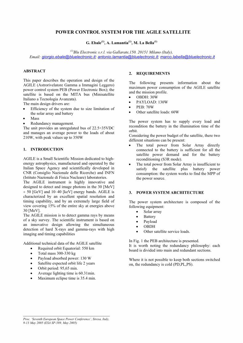
PS’s work in a cold redundant manner and manage CR’s that can work both in cold and hot redundant mode. As shown in Fig.2, the charge regulators (CRM and CRR) are both able to provide 8A max to charge the battery when working in cold redundancy. If needed, OBDH software can decide to supply 12Amax to the battery in hot redundancy configuration.
Fig. 2. Main and Redundant Power Switches and Charge Regulators
The operational modes of the PS plus CR system are:
• Shunt mode • Battery mode
related to the source, either Solar Array or Battery, that provide power to the bus. Both modes are subdivided into two configurations depending on the battery charge regulator CR mode.
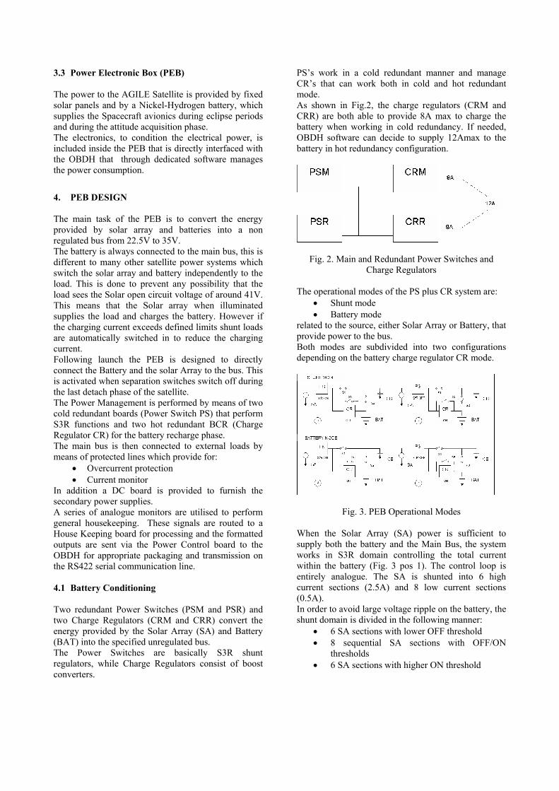
Fig. 3. PEB Operational Modes When the Solar Array (SA) power is sufficient to supply both the battery and the Main Bus, the system works in S3R domain controlling the total current within the battery (Fig. 3 pos 1). The control loop is entirely analogue. The SA is shunted into 6 high current sections (2.5A) and 8 low current sections (0.5A). In order to avoid large voltage ripple on the battery, the shunt domain is divided in the following manner:
• 6 SA sections with lower OFF threshold • 8 sequential SA sections with OFF/ON
thresholds • 6 SA sections with higher ON threshold

As shown in Fig. 4, the error signal (es) swaps all the SA domain, switching ON the 8 low current solar array sections, if the current is still insufficient, a high current section is switched ON and if the resulting SA current is too high the lower current sections in excess are switched OFF; only 1 low current section will continue to work in switching mode to supply exactly the required system current.
Fig. 4. Error Signal vs Operational Modes When the total SA power is lower than the system needs (main bus + battery), a Maximum Power Point Tracking (MPPT) mode is utilised to control the battery charging current (Fig. 3 pos 2). The control comprises an inner analogue control loop and an outer digital control loop:
• The charge regulator CR works in order to control the Battery current through predefined set values
• The MPPT is performed by the external digital control loop as follows:
o Detecting the solar array current and voltage at two different times
o Evaluating the Solar array power at these times and comparing them in order to evaluate the MPP.
o Setting the new charging battery current value as input for the inner analogue control loop.
When the total SA power is lower than the main bus needs, a new configuration is set:
• The current delivered to the node ‘battery + main bus’ (Fig.3 pos 3) is controlled at 8A utilising the S3R domain. When the Solar Array current at Vbattery is no more sufficient, the Maximum Power Point Tracking (MPPT) mode is utilised again to
control the current delivered to the node “battery+main bus” (Fig. 3 pos 4).
4.2 Power Distribution The PEB internal power distribution is provided through a DC/DC converter board (MAIN and RED). Primary power is fed to the DC/DC converter board through a dedicated service board named Power Relay PR. The PR will connect to the battery bus through the separation switch by redundant and fault tolerant linear regulators that will turn off as soon as the PEB internal supply is available. At separation or whenever the PEB internal supply is not available (ideally only at separation) the PR will connect to the battery bus to supply a functional block in charge of performing in the simplest and most reliable way the following basic operations: to connect the internal DC/DC converters to the power bus by latching relays and to perform a switch over from nominal to redundant DC/DC converter branches in the case of a failure detection (input over-current, output under or over voltage). In addition to the above the PR provides power distribution to the OBDH and performs switching and OR-ing of the PEB internal supply lines. At separation the internal nominal branch of the DC/DC converter board and the nominal OBDH are automatically selected. Power distribution to the loads is provided through dedicated boards; each board houses both the MAIN and the RED branches and has been designed to guarantee separation between the two branches from an electrical and thermal point of view. Primary power lines distributed from the PEB are individually protected against short circuit through series n-channel power MOS and dedicated current sensing circuits. The power distribution philosophy is simplified in Fig. 5:
Fig. 5. power distribution philosophy
The power distribution system has been conceived to offer the maximum configuration flexibility when considering potential failures at load level. In the case of failure within the PEB, dedicated current limiters (designed to provide a fold-back current limit in order to decrease power dissipation in failure mode) will isolate the faulty portion of the circuit enabling PEB operation through the remaining branch. In the case of vital loads a cross-trapping scheme has been implemented to enable both nominal and redundant equipments (or parts of the equipment) to be supplied independently from nominal or redundant or both branches of the PEB. This scheme has been adopted, amongst others, to supply the receivers and the transmitters (with the implementation of an additional enable function to avoid operation of both transmitters at the same time also in the case of short-circuit failure of one of the PEB series switch).
Fig. 6 Power Distribution cross-trapping scheme
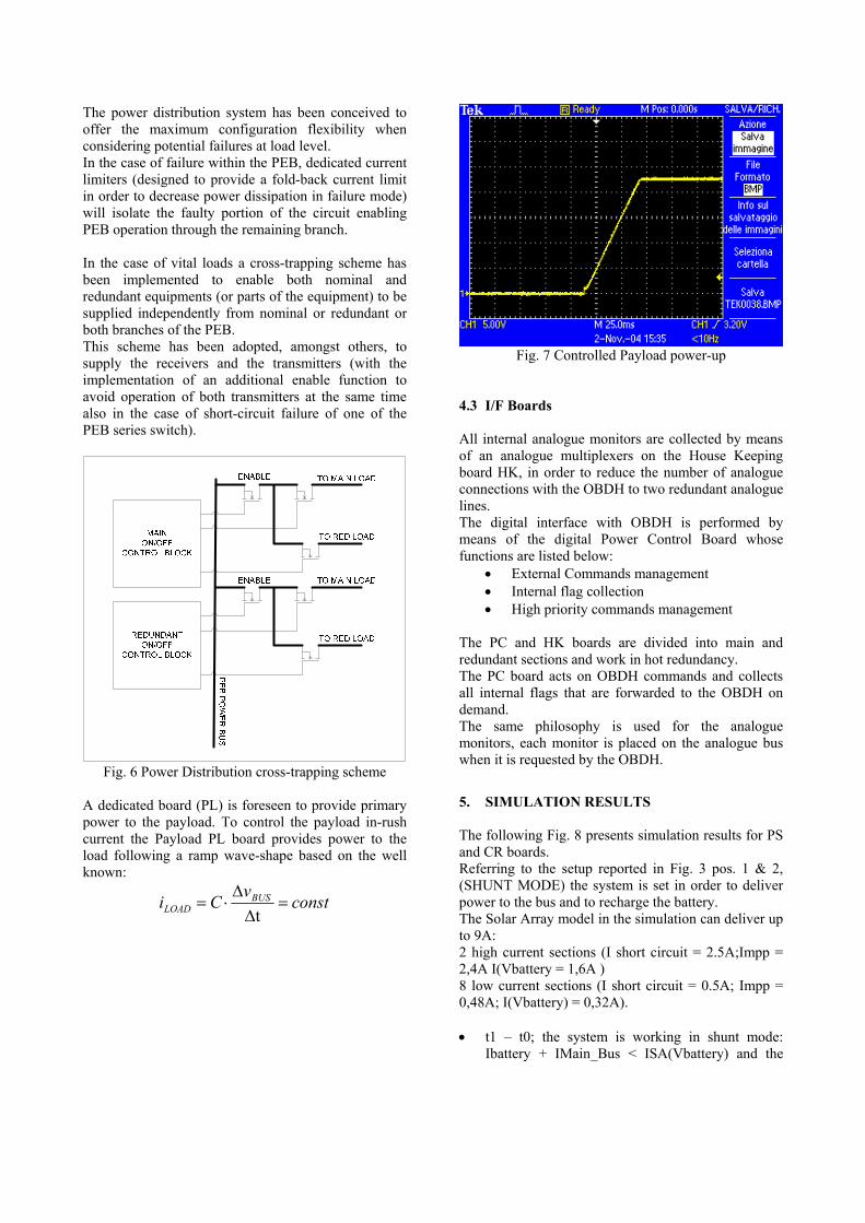
A dedicated board (PL) is foreseen to provide primary power to the payload. To control the payload in-rush current the Payload PL board provides power to the load following a ramp wave-shape based on the well known:
constvCi BUSLOAD =
∆∆⋅=
t
Fig. 7 Controlled Payload power-up
4.3 I/F Boards All internal analogue monitors are collected by means of an analogue multiplexers on the House Keeping board HK, in order to reduce the number of analogue connections with the OBDH to two redundant analogue lines. The digital interface with OBDH is performed by means of the digital Power Control Board whose functions are listed below:
• External Commands management • Internal flag collection • High priority commands management
The PC and HK boards are divided into main and redundant sections and work in hot redundancy. The PC board acts on OBDH commands and collects all internal flags that are forwarded to the OBDH on demand. The same philosophy is used for the analogue monitors, each monitor is placed on the analogue bus when it is requested by the OBDH.
5. SIMULATION RESULTS The following Fig. 8 presents simulation results for PS and CR boards. Referring to the setup reported in Fig. 3 pos. 1 & 2, (SHUNT MODE) the system is set in order to deliver power to the bus and to recharge the battery. The Solar Array model in the simulation can deliver up to 9A: 2 high current sections (I short circuit = 2.5A;Impp = 2,4A I(Vbattery = 1,6A ) 8 low current sections (I short circuit = 0.5A; Impp = 0,48A; I(Vbattery) = 0,32A). • t1 – t0; the system is working in shunt mode:
Ibattery + IMain_Bus < ISA(Vbattery) and the

requested current is Ibattery = 2A, IMain_Bus = 1A. This means that the system can work in S3R mode with at least 1 high current section on, some low current sections on and others off, always 1 low current section switching with the correct duty cycle set to deliver the right current value.
• t2 –t1, the IBatt_curr_set vary from 2A to 4A in 15ms, every low current shunt section switches on to deliver the requested current, if it is not sufficient, the error signal runs until the second high current section switches on. Then, if the current delivered by the Solar Array is not
sufficient, the system evolves to the CR domain, otherwise the error signal finds the new working point switching off the low current sections in excess.
• t3 – t2 IMain_Bus rises from 1A to 3A, the S3R is not able to deliver power enough to fulfil the total power request, so the error signal runs to the CR domain where the system reaches a new working point, varying the Solar Array voltage and approaching the MPP of the system.
Time
8.00ms 12.00ms 16.00ms 20.00ms 24.00ms 28.00ms 32.00ms 36.00ms4.33ms 39.96msV(to_shunt) I(Main_Bus)
10.0
-2.4
18.6
SEL>>
V(Main_Bus)33.2V
33.6V
34.0V
34.4V
Fig. 8 Simulation results
t0 t1 t2 t3

6. INTEGRATION Then following presents some pictures taken during the PEB integration.
Fig. 9 Power Distribution board
Fig. 10 CR and PS during test
7. ACKNOLEDGMENT
We want to thank Francesco Barresi and Terry Stock for their collaboration to this work.
8. REFERENCES
1. D.O’sullivan- A.Weinberg : The sequential switching shunt regulator S3R-. Proceeding of the spacecraft power conditioning-21-23 sept 77-Nordwijk The Nederlands.
2. P.Perol-D. Olsson-J. Haines : Power system architecture for regulated bus with battery below bus. –ESA/PAT/412- Oct 98.
3. A. Capel-P.Perol: Comparative performance evaluation between the S4R and S3R regulated bus topologies. ESA SP-502, May-2002