POWER AMPLIFIER LINEARIZATION USING …...POWER AMPLIFIER LINEARIZATION USING DIGIITAL PR...
6
POWER AMPLIFIER LINEARIZATION USING DIGIITAL PREDISTORTION Hamid Ali 1 , Manoj Gupta 2 [email protected] 1 ,[email protected] 2 Shobhit University Meerut Abstract: For wideband or high power applications, the power amplifier exhibits memory effects, for which memory less predistorters can achieve only limited linearization performance. The memory polynomial predistorter can correct both the nonlinear distortions and the linear frequency response that may exist in the power amplifier. It is a robust predistorter, which has demonstrated good performance on several nonlinear system models. The predistorter models considered in this paper include both even- and odd order nonlinear terms. Here, the benefits to include even- order nonlinear terms in both the baseband power amplifier and predistorter models are described. Introduction: Power amplifiers are indispensable components in a communication system and are inherently nonlinear. The nonlinearity generates spectral regrowth, which leads to adjacent channel interference and violations of the out-of-band emission requirements mandated by regulatory bodies. It also causes in-band distortion, which degrades the bit error rate (BER) performance. To reduce the nonlinearity, the power amplifier can be backed off to operate within the linear portion of its operating curve. However, newer transmission formats, such as wideband code division multiple access (WCDMA) and orthogonal frequency division multiplexing (OFDM), have high peak to average power ratios, i.e., large fluctuations in their signal envelopes. This means that the power amplifier needs to be backed off far from its saturation point, which results in very low efficiencies, typically less than 10% ; i.e., more than 90% of the dc power is lost and turns into heat. Fig 1: Digital predistortion block diagram Digital predistortion implementations in the current literature mostly focus on the power amplifier that has a memoryless nonlinearity; i.e., the current output depends only on the current input through a nonlinear mechanism. This instantaneous nonlinearity is usually characterized by the AM/AM and AM/PM responses of the power amplifier, where the output signal amplitude and phase deviation of the power amplifier output are given as functions of the amplitude of its current input. There has been intensive research on predistortion techniques for memoryless power amplifiers during the past decade. As the signal bandwidth gets wider, such as in WCDMA, power amplifiers begin to exhibit memory effects. In other words, the power amplifier becomes a nonlinear system with memory. For such a power amplifier, memoryless predistortion can achieve only very limited linearization performance .Therefore, digital predistorters also need to have memory structures. This paper investigates robust predistorter models that are capable of linearizing power amplifiers with memory effects. It also investigates system implementation issues related to these wideband digital predistortion systems. International Journal of Scientific & Engineering Research, Volume 6, Issue 5, May-2015 ISSN 2229-5518 80 IJSER © 2015 http://www.ijser.org IJSER
Transcript of POWER AMPLIFIER LINEARIZATION USING …...POWER AMPLIFIER LINEARIZATION USING DIGIITAL PR...
POWER AMPLIFIER LINEARIZATION USING DIGIITAL
PREDISTORTION
Hamid Ali 1, Manoj Gupta
2
[email protected],[email protected]
2
Shobhit University Meerut
Abstract: For wideband or high power
applications, the power amplifier exhibits
memory effects, for which memory less
predistorters can achieve only limited
linearization performance. The memory
polynomial predistorter can correct both the
nonlinear distortions and the linear
frequency response that may exist in the
power amplifier. It is a robust predistorter,
which has demonstrated good performance
on several nonlinear system models. The
predistorter models considered in this paper
include both even- and odd order nonlinear
terms. Here, the benefits to include even-
order nonlinear terms in both the baseband
power amplifier and predistorter models are
described.
Introduction:
Power amplifiers are indispensable
components in a communication system and
are inherently nonlinear. The nonlinearity
generates spectral regrowth, which leads to
adjacent channel interference and violations
of the out-of-band emission requirements
mandated by regulatory bodies. It also causes
in-band distortion, which degrades the bit
error rate (BER) performance. To reduce the
nonlinearity, the power amplifier can be
backed off to operate within the linear
portion of its operating curve. However,
newer transmission formats, such as
wideband code division multiple access
(WCDMA) and orthogonal frequency
division multiplexing (OFDM), have high
peak to average power ratios, i.e., large
fluctuations in their
signal envelopes. This means that the power
amplifier needs to be backed off far from its
saturation point, which results in very low
efficiencies, typically less than 10% ; i.e.,
more than 90% of the dc power is lost and
turns into heat.
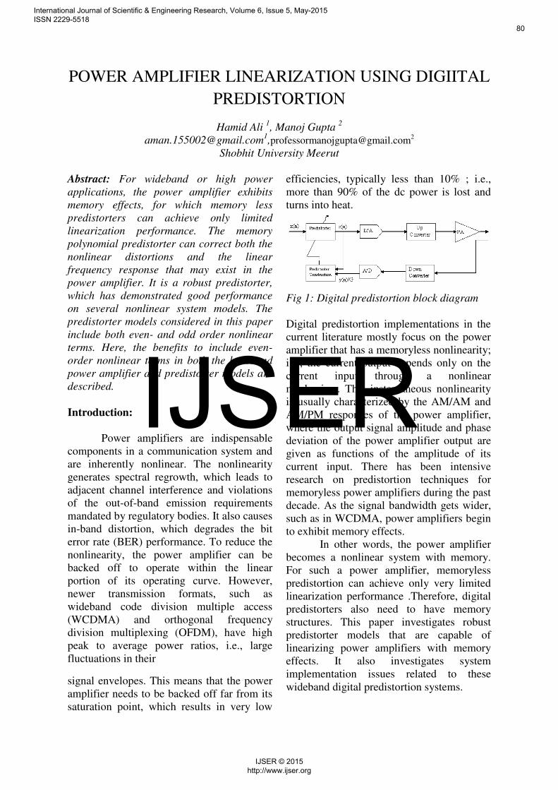
Fig 1: Digital predistortion block diagram
Digital predistortion implementations in the
current literature mostly focus on the power
amplifier that has a memoryless nonlinearity;
i.e., the current output depends only on the
current input through a nonlinear
mechanism. This instantaneous nonlinearity
is usually characterized by the AM/AM and
AM/PM responses of the power amplifier,
where the output signal amplitude and phase
deviation of the power amplifier output are
given as functions of the amplitude of its
current input. There has been intensive
research on predistortion techniques for
memoryless power amplifiers during the past
decade. As the signal bandwidth gets wider,
such as in WCDMA, power amplifiers begin
to exhibit memory effects.
In other words, the power amplifier
becomes a nonlinear system with memory.
For such a power amplifier, memoryless
predistortion can achieve only very limited
linearization performance .Therefore, digital
predistorters also need to have memory
structures. This paper investigates robust
predistorter models that are capable of
linearizing power amplifiers with memory
effects. It also investigates system
implementation issues related to these
wideband digital predistortion systems.
International Journal of Scientific & Engineering Research, Volume 6, Issue 5, May-2015 ISSN 2229-5518
80
IJSER © 2015 http://www.ijser.org
IJSER

Gain and Output Power:
In mobile communications each
system has its specifications which must be
fulfilled. Obtaining output powers high
enough for various applications is a very
important task achieved by Power
Amplifiers. In general the information signal
is first modulated and up converted, and then
sent to a PA. This input is multiplied with a
gain factor and the desired output power is
obtained. Gain is handled in dB and power in
dBm throughout this thesis. Fig.2 and 3
show example PA output and gain versus
input power characteristics of a linear PA
respectively. PA output versus input power
characteristics shown in fig. 2 is also called
AM/AM characteristics of the PA As it can
be seen from the figures the gain is constant
for low input powers and it reduces with
approaching its saturation region. Saturation
region is easily visible from the output power
curve where the output power stays constant
with further increase of the input power. In
the
Fig 2. Output power characteristics of power
amplifier
fig. 3 1 dB compression point is also shown,
which refers to the output power level at
which the amplifier’s transfer characteristics deviates from the ideal one by 1 dB [3]. This
is a widely used measure of amplifier
linearity revealing roughly which linear
output power value is achievable with the
device under test (DUT).
Fig 3: Gain of the Power amplifier
Review of Power Amplifier
LinearizationMethods:
Power amplifier linearization is currently one
of the most promising techniques for
linearity and efficiency improvement in
mobile communication systems. There are
numerous techniques which have different
levels of complexity, various advantages and
limitations [2]. Different linearization
methods may fit to different communication
systems. For example more sophisticated
high performance systems may be used for
base station PAs whereas the systems usable
in handsets should have low complexity, low
cost and high efficiency. Although in general
the main reason to implement these systems
is to linearize the PA, they improve also the
efficiency because a linearized PA can be
driven closer to compression (operation with
low back-off). In the following sections
several PA linearization methods are
explained which can be classified mainly as
feedback, feedforward and predistortion
systems.
-25 -20 -15 -10 -5 0 5 1016
18
20
22
24
26
28
Pin (dBm)
Gain
(dB
)
-20 -15 -10 -5 0 56
8
10
12
14
16
18
20
22
24
Pin (dBm)
Pout
(dB
m)
International Journal of Scientific & Engineering Research, Volume 6, Issue 5, May-2015 ISSN 2229-5518
81
IJSER © 2015 http://www.ijser.org
IJSER
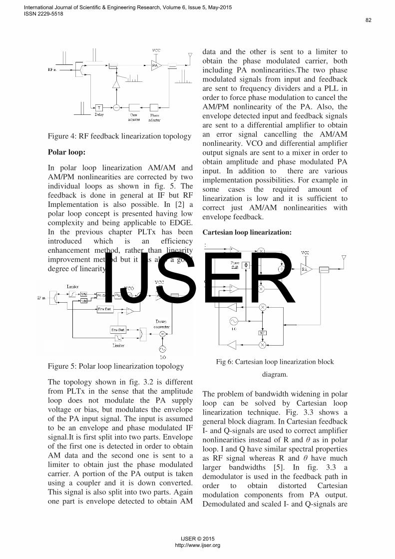
Figure 4: RF feedback linearization topology
Polar loop:
In polar loop linearization AM/AM and
AM/PM nonlinearities are corrected by two
individual loops as shown in fig. 5. The
feedback is done in general at IF but RF
Implementation is also possible. In [2] a
polar loop concept is presented having low
complexity and being applicable to EDGE.
In the previous chapter PLTx has been
introduced which is an efficiency
enhancement method, rather than linearity
improvement method but it has also a good
degree of linearity.
Figure 5: Polar loop linearization topology
The topology shown in fig. 3.2 is different
from PLTx in the sense that the amplitude
loop does not modulate the PA supply
voltage or bias, but modulates the envelope
of the PA input signal. The input is assumed
to be an envelope and phase modulated IF
signal.It is first split into two parts. Envelope
of the first one is detected in order to obtain
AM data and the second one is sent to a
limiter to obtain just the phase modulated
carrier. A portion of the PA output is taken
using a coupler and it is down converted.
This signal is also split into two parts. Again
one part is envelope detected to obtain AM
data and the other is sent to a limiter to
obtain the phase modulated carrier, both
including PA nonlinearities.The two phase
modulated signals from input and feedback
are sent to frequency dividers and a PLL in
order to force phase modulation to cancel the
AM/PM nonlinearity of the PA. Also, the
envelope detected input and feedback signals
are sent to a differential amplifier to obtain
an error signal cancelling the AM/AM
nonlinearity. VCO and differential amplifier
output signals are sent to a mixer in order to
obtain amplitude and phase modulated PA
input. In addition to there are various
implementation possibilities. For example in
some cases the required amount of
linearization is low and it is sufficient to
correct just AM/AM nonlinearities with
envelope feedback.
Cartesian loop linearization:
Fig 6: Cartesian loop linearization block
diagram.
The problem of bandwidth widening in polar
loop can be solved by Cartesian loop
linearization technique. Fig. 3.3 shows a
general block diagram. In Cartesian feedback
I- and Q-signals are used to correct amplifier
nonlinearities instead of R and θ as in polar
loop. I and Q have similar spectral properties
as RF signal whereas R and θ have much
larger bandwidths [5]. In fig. 3.3 a
demodulator is used in the feedback path in
order to obtain distorted Cartesian
modulation components from PA output.
Demodulated and scaled I- and Q-signals are
International Journal of Scientific & Engineering Research, Volume 6, Issue 5, May-2015 ISSN 2229-5518
82
IJSER © 2015 http://www.ijser.org
IJSER
subtracted from the input I- and Q-signals to
obtain the PA input baseband signals
resulting in linear operation The circuit in
fig. 3.3 is implemented in RF because IF
Cartesian loop is undesirable due to the
additional delay added to feedback loop.
Predistortion:
The idea behind predistortion is to expand
the input signal prior a PA in such a way that
the nonlinearities due to the PA are
compensated. It is realized by implementing
a nonlinear block in front of the nonlinear
PA generating input signal level dependent
distortion elements opposite of the distortion
caused by the PA. As a result the cascade of
these nonlinear blocks has a linear response.
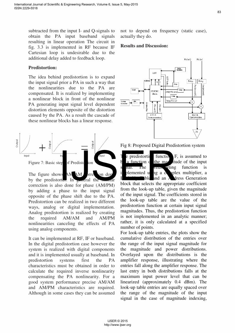
Figure 7: Basic steps of Predistortion
The figure shows AM/AM correction done
by the predistorter. In general the similar
correction is also done for phase (AM/PM)
by adding a phase to the input signal
opposite of the phase shift due to the PA.
Predistortion can be realized in two different
ways, analog or digital implementation.
Analog predistortion is realized by creating
the required AM/AM and AM/PM
nonlinearities canceling the effects of PA
using analog components.
It can be implemented at RF, IF or baseband.
In the digital predistortion case however the
system is realized with digital components
and it is implemented usually at baseband. In
predistortion systems first the PA
characteristics must be obtained in order to
calculate the required inverse nonlinearity
compensating the PA nonlinearity. For a
good system performance precise AM/AM
and AM/PM characteristics are required.
Although in some cases they can be assumed
not to depend on frequency (static case),
actually they do.
Results and Discussion:
Fig 8: Proposed Digital Predistortion system
The predistorting function, F, is assumed to
be a function of the magnitude of the input
signal. The predistorting function is
implemented using a complex multiplier, a
Look-Up Table and an Address Generation
block that selects the appropriate coefficient
from the look-up table, given the magnitude
of the input signal. The coefficients stored in
the look-up table are the value of the
predistortion function at certain input signal
magnitudes. Thus, the predistortion function
is not implemented in an analytic manner;
rather, it is only calculated at a specified
number of points.
For look-up table entries, the plots show the
cumulative distribution of the entries over
the range of the input signal magnitude for
the magnitude and power distributions.
Overlayed upon the distributions is the
amplifier response, illustrating where the
entries fall along the amplifier response. The
last entry in both distributions falls at the
maximum input power level that can be
linearized (approximately 0.4 dBm). The
look-up table entries are equally spaced over
the range of the magnitude of the input
signal in the case of magnitude indexing,
International Journal of Scientific & Engineering Research, Volume 6, Issue 5, May-2015 ISSN 2229-5518
83
IJSER © 2015 http://www.ijser.org
IJSER

whereas, more look-up table entries are
distributed at the higher end of the range in
the case of power indexing.
Figure 9: Magnitude and phase of the
1. Error Vector Magnitude:
EVM for non-predistortion system
EVM for Predistortion system EVM
= 102.6331%
2. Average Error Vector Magnitude:
Average EVM for non-predistortion system
= 108.7263%,
Average EVM for predistortion system EVM
= 102.6331%
EVM reduction over non_predistortion
= 5.604%
3. Mean values over last 500 input
samples: Non-Predistorted system:
Absolute Phase Error = 3421.21545
Absolute Magnitude Error
=1049.64671
4. Mean values over last 500 input
samples: Predistorted system:
Absolute Phase Error
=3077.30933
Absolute Magnitude Error
= 1007.00127
5. Predistorted reduction compared to
non-predistortion:
Mean Absolute Phase Error reduction
= 10.052%
Mean Absolute Magnitude Error reduction
= 4.063%
6. Predistortion: 3rd order:
Average sideband magnitude
=-55.360dB,
Max sideband magnitude
=-28.364dB
7. Predistortion: 5th order:
Average sideband magnitude = -70.594dB,
Max sideband magnitude = -47.468dB
No Predistortion 3rd
order:
Average sideband magnitude = -57.124dB,
Max sideband magnitude = -32.873dB
No Predistortion: 5th
order:
Average sideband magnitude =-84.975dB,
Max sideband magnitude = -55.535dB
Fig 10: Normalized Linearity of Power amplefier
Figure 11:frequency plot for DPD system
0 500 1000 1500 2000 2500 3000-1
-0.5
0
0.5
1
Voltage level
Real Part
Input
Output
0 500 1000 1500 2000 2500 3000-1
-0.5
0
0.5
1
Voltage level
Imaginary Part
Input
Output
0 500 1000 1500 2000 2500 3000-1
-0.5
0
0.5
1
Time (samples)
Voltage level
Linearity Error
Real
Imag
0 500 1000 1500 2000 2500 3000-300
-200
-100
0Source data in
0 500 1000 1500 2000 2500 3000-150
-100
-50
0
50PA output with no predistortion
0 500 1000 1500 2000 2500 3000-150
-100
-50
0
50PA output WITH predistortion
magnitude (
dB
)
Frequency index
International Journal of Scientific & Engineering Research, Volume 6, Issue 5, May-2015 ISSN 2229-5518
84
IJSER © 2015 http://www.ijser.org
IJSER
Conclusion:
This paper considered the design of digital
predistortion systems to linearize power
amplifiers with memory effects. By adding a
digital predistorter in the base band, the
power amplifier is allowed to operate into its
nonlinear region, thereby significantly
increasing its efficiency. The efficiency gain
translates into electricity and cooling cost
savings for service providers and longer
battery life for mobile terminal users. The
challenge here is to address the memory
effects exhibited by the higher power
amplifiers or the power amplifiers for
wideband signals. In addition, analog
components in the transmitter have
imperfections that need to be compensated as
well.
References:
1. NavidLashkarian, Chris Dick FPGA
implementation of digital predistortion
linearizers for wideband power
Amplifiers; Signal Processing Division,
Xilinx Inc., San Jose, USA,.2007.
2. Lei Ding, Digital Predistortion of Power
Amplifiers for Wireless Applications;
2004.
3. Cripps, S.C.: RF power 2005. Microwave
Journal 48 (2005), 22-36.
4. Euns, C.; Powers, E.J.: A new
Volterrapredistorter based on the indirect
learning architecture. IEEE Tran. On
Signal Processing 45 (1997), 223-227.
5. Kim, J.; Konstantinou, K.: Digital
predistortion of wideband signals based
on power amplifier model with memory.
Electronics Letters 37 (2001), 1417-
1418.
6. NazimCeylan Linearization of power
amplifiers by means of digital
predistortion– Erlangen 2005.
7. García, P.; Ortega, A.; de Mingo, J.;
Valdovinos, A.: Nonlinear distortion
cancellation sings LINC transmitters in
OFDM systems. IEEE Trans. On
Broadcasting 51 (2005), 84-93.
8. Altera , Digital Predistortion Reference
Design, Altera corporation, 2006
9. Shawn P. Stapleton, Agilent EEs of EDA
Digital Predistortion of Power Amplifiers
in cooperation with: Agilent
Technologies, Inc, 2005.
10. Ding, L.; Raich, R.; Zhou, G.T.: A
Hammerstein predistortion linearization
design based on the indirect learning.
IEEE Int. Conf. on Acoustics, Speech,
Signal Proc. 3 (2002), 2689-2692.
11. Jung, W.J.; Kim, W.R.; Kim, K.M.; Lee,
K.B.: Digital predistorter using multiple
lookup tables. IEEE Electronics Letters
39 (2003), 1386-1388.
12. Baudoin, G.; Jardin, P.: Adaptive
polynomial pre-distortion for
linearization of power amplifiers in
wireless communications and WLAN.
Int. Conf. on Trends in Comm.
EUROCON 2001 1, 157-160.
13. Marsalek, R.; Jardin, P.; Baudoin, G.:
From post-distortion to pre-distortion for
power amplifiers linearization. IEEE
Electronics Letters 7 (2003), 308-310.
14. Ma, Z., Zierdt, M., Dunkleberger, L., and
Pastalan, J., “Memoryless power Amplifier characterization for digital
baseband predistortion (ii).” unpublished work, Jan. 2001.
International Journal of Scientific & Engineering Research, Volume 6, Issue 5, May-2015 ISSN 2229-5518
85
IJSER © 2015 http://www.ijser.org
IJSER