Powder Technology From Landslides and Avalanches to ...
84
1 LTP ÉCOLE POLYTECHNIQUE FÉDÉRALE DE LAUSANNE Powder Technology From Landslides and Avalanches to Concrete and Chocolate Prof. P. Bowen (EPFL), Dr. P. Derlet (PSI) WEEK 14 – file no. 12 Sintering Mechanisms & New Technologies- (4) New Technologies – Sintering Methods
Transcript of Powder Technology From Landslides and Avalanches to ...
1
LTPÉCOLE POLYTECHNIQUE FÉDÉRALE DE LAUSANNE
Powder Technology
From Landslides and Avalanches to Concrete
and Chocolate
Prof. P. Bowen (EPFL), Dr. P. Derlet (PSI)
WEEK 14 – file no. 12
Sintering Mechanisms & New Technologies- (4)
New Technologies – Sintering Methods
Today’s Objectives
Last Week
• Standard forming methods…..ceramics and metals
– Dry Pressing
– Wet methods – overview - slip casting, injection moulding
– Limitations …additive manufacturing approach
– General intro to additive manufacturing
– Additive manufacturing and sintering combined – SLS
This week …
• Summary of standard sintering methods and procedures
– Isothermal, controlled rate, two-step, hot press, hot isostatic pressing
– Solid state, liquid phase, reactive sintering
• New sintering processes, Spark Plasma Sintering, flash sintering, cold sintering…
• Typical questions, Powder Technology – Learning outcomes,
• Exam….
4
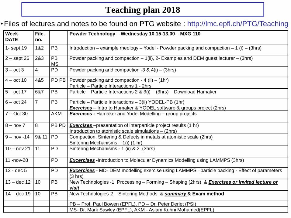
Teaching plan 2018
•Files of lectures and notes to be found on PTG website : http://lmc.epfl.ch/PTG/Teaching
Week-
DATE
File.
no.
Powder Technology – Wednesday 10.15-13.00 – MXG 110
1- sept 19 1&2 PB Introduction – example rheology – Yodel - Powder packing and compaction – 1 (i) – (3hrs)
2 – sept 26 2&3 PB
MS
Powder packing and compaction – 1(ii), 2- Examples and DEM guest lecturer – (3hrs)
3 – oct 3 4 PD Powder packing and compaction -3 & 4(i) – (3hrs)
4 – oct 10 4&5 PD PB Powder packing and compaction - 4 (ii) – (1hr)
Particle – Particle Interactions 1 - 2hrs
5 – oct 17 6&7 PB Particle – Particle Interactions 2 & 3(i) – (3hrs) – Download Hamaker
6 – oct 24 7 PB Particle – Particle Interactions – 3(ii) YODEL-PB (1hr)
Exercises – Intro to Hamaker & YODEL software & groups project (2hrs)
7 – Oct 30 AKM Exercises - Hamaker and Yodel Modelling – group projects
8 – nov 7 8 PB PD Exercises –presentation of interparticle project results (1 hr)
Introduction to atomistic scale simulations – (2hrs)
9 – nov -14 9& 11 PD Compaction, Sintering & Defects in metals at atomistic scale (2hrs)
Sintering Mechanisms – 1(i) (1 hr)
10 – nov 21 11 PD Sintering Mechanisms - 1 (ii) & 2 (3hrs)
11 -nov-28 PD Excercises -Introduction to Molecular Dynamics Modelling using LAMMPS (3hrs) .
12 - dec 5 PD Excercises - MD- DEM modelling exercise using LAMMPS –particle packing - Effect of parameters
(3 hrs)
13 – dec 12 10 PB New Technologies -1 Processing – Forming – Shaping (2hrs) & Exercises or invited lecture or
visit
14 – dec 19 10 PB New Technologies-2 – Sintering Methods & summary & Exam method
PB – Prof. Paul Bowen (EPFL), PD – Dr. Peter Derlet (PSI)
MS- Dr. Mark Sawley (EPFL), AKM - Aslam Kuhni Mohamed(EPFL)
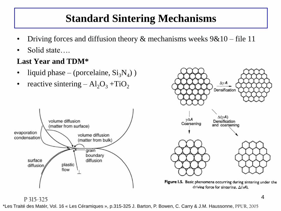
Standard Sintering Mechanisms
• Driving forces and diffusion theory & mechanisms weeks 9&10 – file 11
• Solid state….
Last Year and TDM*
• liquid phase – (porcelaine, Si3N4) )
• reactive sintering – Al2O3 +TiO2
4P 315-325*Les Traité des Matér, Vol. 16 « Les Céramiques », p.315-325 J. Barton, P. Bowen, C. Carry & J.M. Haussonne, PPUR, 2005
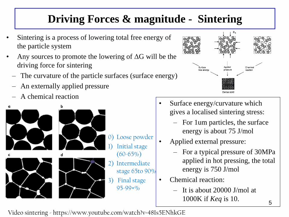
Driving Forces & magnitude - Sintering
5
• Sintering is a process of lowering total free energy of
the particle system
• Any sources to promote the lowering of ΔG will be the
driving force for sintering
– The curvature of the particle surfaces (surface energy)
– An externally applied pressure
– A chemical reaction• Surface energy/curvature which
gives a localised sintering stress:
– For 1um particles, the surface
energy is about 75 J/mol
• Applied external pressure:
– For a typical pressure of 30MPa
applied in hot pressing, the total
energy is 750 J/mol
• Chemical reaction:
– It is about 20000 J/mol at
1000K if Keq is 10.
0) Loose powder
1) Initial stage (60-65%)
2) Intermediatestage 65to 90%
3) Final stage 95-99+%
Video sintering - https://www.youtube.com/watch?v=48Is5ENhkGE

Standard Sintering Methods
• Isothermal (a)
• Controlled rate (b)
• Two-step (c)
• Hot Pressing (d)
• Hot Isostatic Pressing (e)
6
(a) (b)
(e)
Loh et al. Ceram.Int. 42(2016)12556–12572
(c)
www.dynacer.com/processing/hot-pressing
(d)
graphite
Bocanegra-Bernal, J.Mater.Sci.
39 (2004) 6399 – 6420
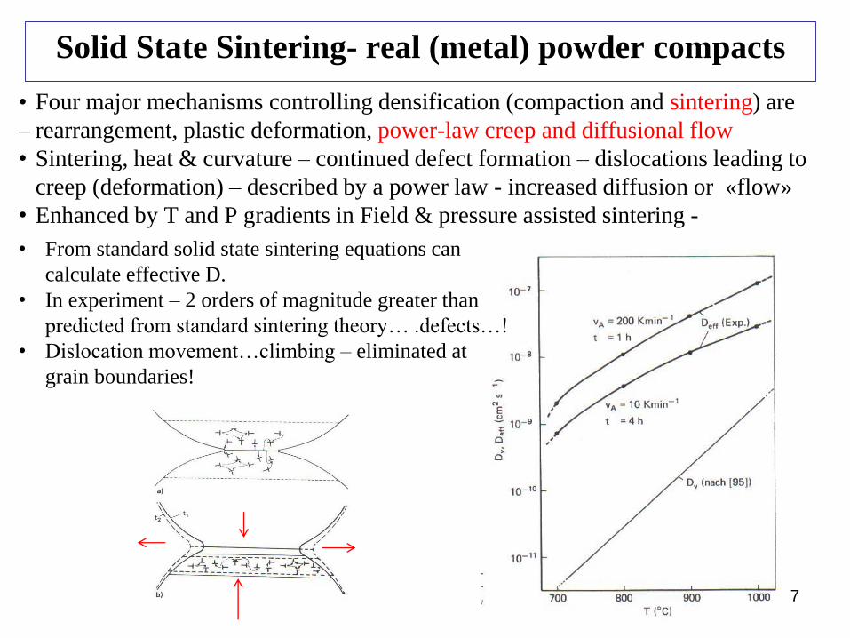
Solid State Sintering- real (metal) powder compacts
7
• From standard solid state sintering equations can
calculate effective D.
• In experiment – 2 orders of magnitude greater than
predicted from standard sintering theory… .defects…!
• Dislocation movement…climbing – eliminated at
grain boundaries!
• Four major mechanisms controlling densification (compaction and sintering) are
– rearrangement, plastic deformation, power-law creep and diffusional flow
• Sintering, heat & curvature – continued defect formation – dislocations leading to
creep (deformation) – described by a power law - increased diffusion or «flow»
• Enhanced by T and P gradients in Field & pressure assisted sintering -
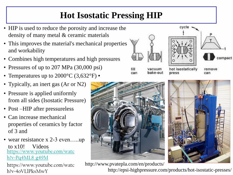
Hot Isostatic Pressing HIP
http://www.pvatepla.com/en/products/
http://epsi-highpressure.com/products/hot-isostatic-presses/
• HIP is used to reduce the porosity and increase the
density of many metal & ceramic materials
• This improves the material's mechanical properties
and workability
• Combines high temperatures and high pressures
• Pressures of up to 207 MPa (30,000 psi)
• Temperatures up to 2000°C (3,632°F) ▪
• Typically, an inert gas (Ar or N2)
• Pressure is applied uniformly
from all sides (Isostatic Pressure)
• Post –HIP after pressureless
• Can increase mechanical
properties of ceramics by factor
of 3 and
• wear resistance x 2-3 even…..up
to x10! Videoshttps://www.youtube.com/watch?v=Pq4ML8_g49M
https://www.youtube.com/watch?v=4oVLlPksMwY
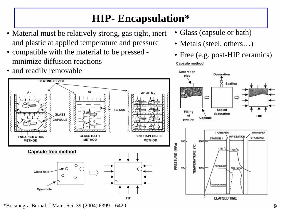
HIP- Encapsulation*
• Material must be relatively strong, gas tight, inert
and plastic at applied temperature and pressure
• compatible with the material to be pressed -
minimize diffusion reactions
• and readily removable
9
• Glass (capsule or bath)
• Metals (steel, others…)
• Free (e.g. post-HIP ceramics)
*Bocanegra-Bernal, J.Mater.Sci. 39 (2004) 6399 – 6420
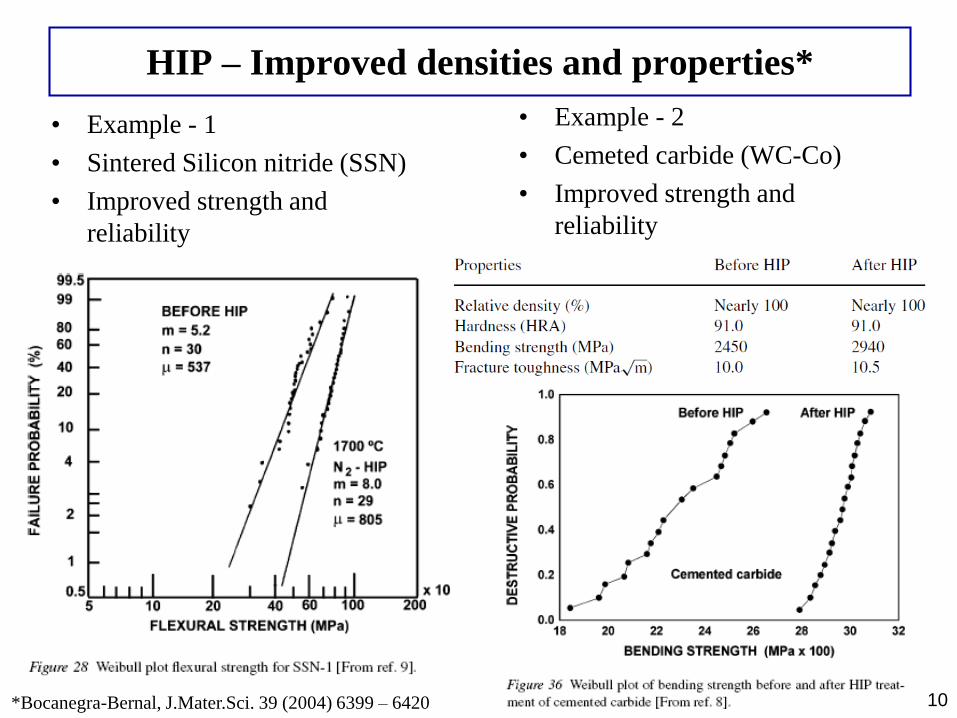
HIP – Improved densities and properties*
• Example - 1
• Sintered Silicon nitride (SSN)
• Improved strength and
reliability
10
• Example - 2
• Cemeted carbide (WC-Co)
• Improved strength and
reliability
*Bocanegra-Bernal, J.Mater.Sci. 39 (2004) 6399 – 6420
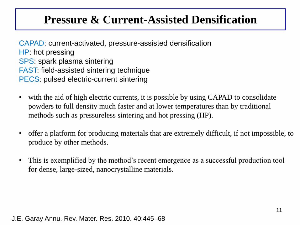
Pressure & Current-Assisted Densification
11
CAPAD: current-activated, pressure-assisted densification
HP: hot pressing
SPS: spark plasma sintering
FAST: field-assisted sintering technique
PECS: pulsed electric-current sintering
• with the aid of high electric currents, it is possible by using CAPAD to consolidate
powders to full density much faster and at lower temperatures than by traditional
methods such as pressureless sintering and hot pressing (HP).
• offer a platform for producing materials that are extremely difficult, if not impossible, to
produce by other methods.
• This is exemplified by the method’s recent emergence as a successful production tool
for dense, large-sized, nanocrystalline materials.
J.E. Garay Annu. Rev. Mater. Res. 2010. 40:445–68
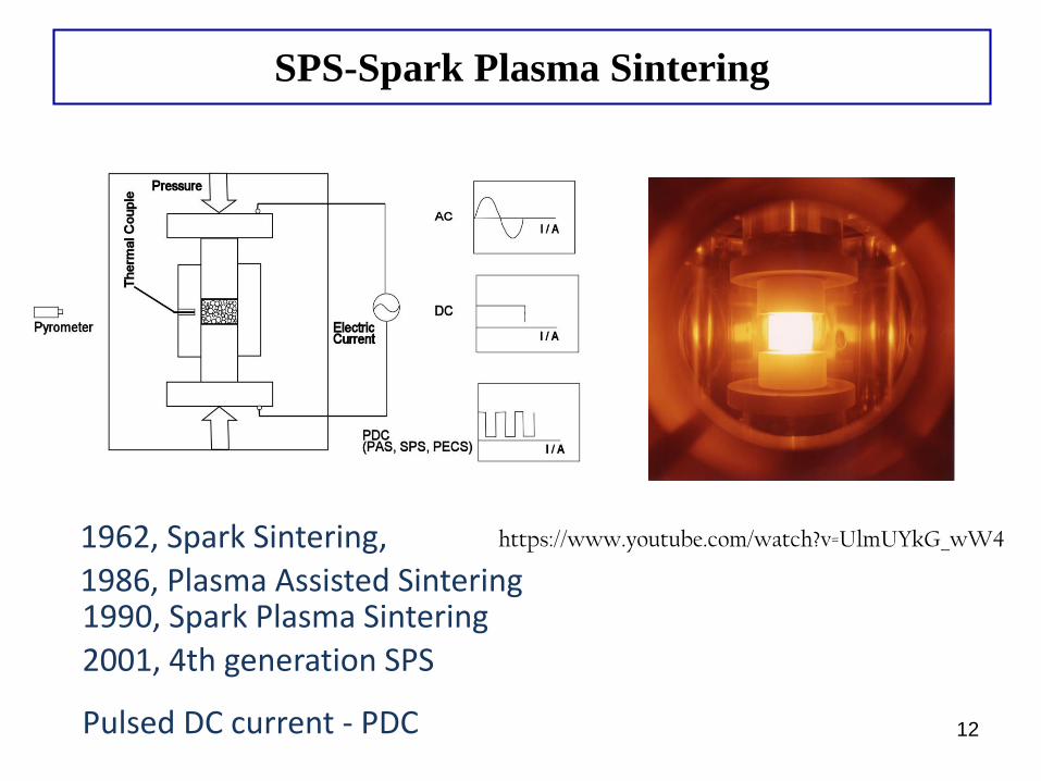
SPS-Spark Plasma Sintering
1962, Spark Sintering,
1986, Plasma Assisted Sintering1990, Spark Plasma Sintering
2001, 4th generation SPS
Pulsed DC current - PDC 12
https://www.youtube.com/watch?v=UlmUYkG_wW4
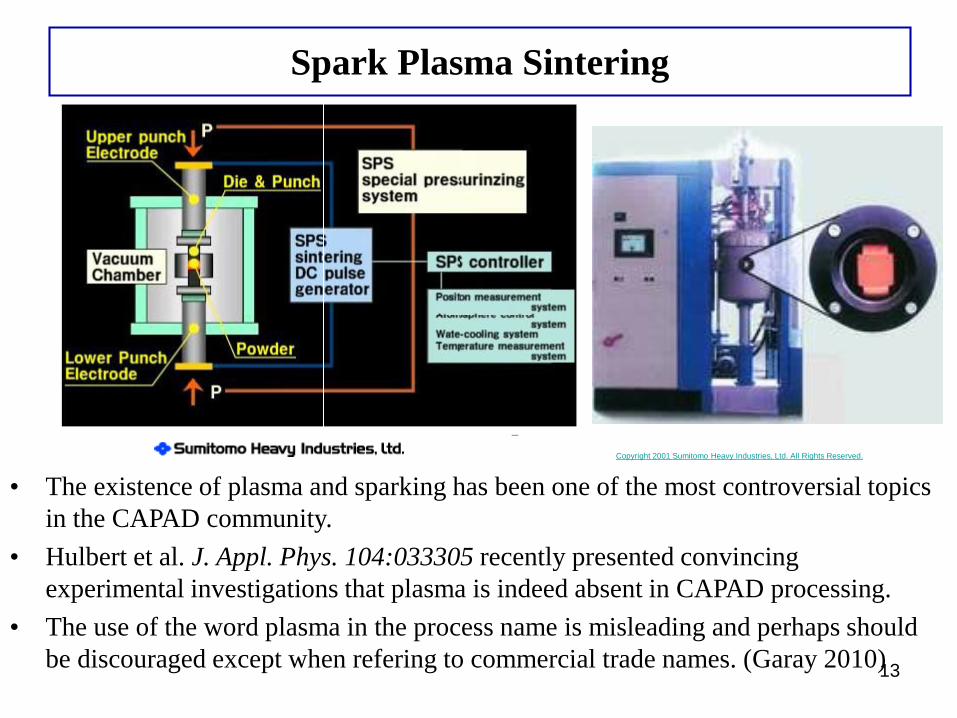
Spark Plasma Sintering
• The existence of plasma and sparking has been one of the most controversial topics
in the CAPAD community.
• Hulbert et al. J. Appl. Phys. 104:033305 recently presented convincing
experimental investigations that plasma is indeed absent in CAPAD processing.
• The use of the word plasma in the process name is misleading and perhaps should
be discouraged except when refering to commercial trade names. (Garay 2010)13
Copyright 2001 Sumitomo Heavy Industries, Ltd. All Rights Reserved.
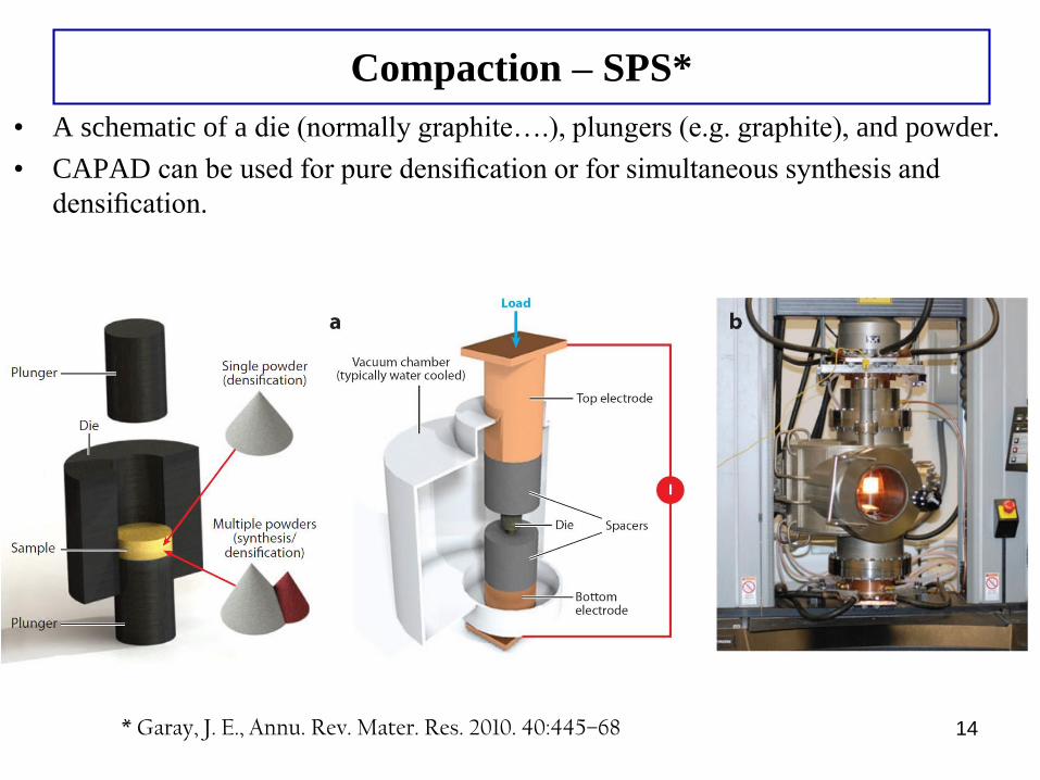
Compaction – SPS*
• A schematic of a die (normally graphite….), plungers (e.g. graphite), and powder.
• CAPAD can be used for pure densification or for simultaneous synthesis and
densification.
14* Garay, J. E., Annu. Rev. Mater. Res. 2010. 40:445–68
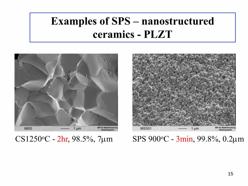
CS1250oC - 2hr, 98.5%, 7mm SPS 900oC - 3min, 99.8%, 0.2mm
Examples of SPS – nanostructured
ceramics - PLZT
15
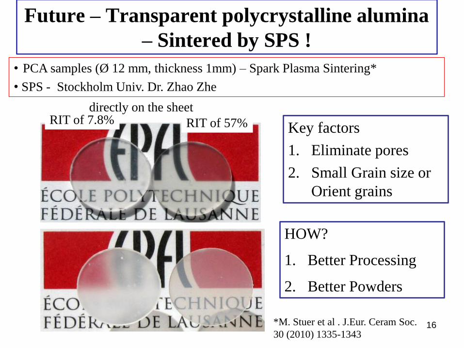
Future – Transparent polycrystalline alumina
– Sintered by SPS !
16
RIT of 7.8% RIT of 57%
directly on the sheet
• PCA samples (Ø 12 mm, thickness 1mm) – Spark Plasma Sintering*
• SPS - Stockholm Univ. Dr. Zhao Zhe
*M. Stuer et al . J.Eur. Ceram Soc.
30 (2010) 1335-1343
Key factors
1. Eliminate pores
2. Small Grain size or
Orient grains
HOW?
1. Better Processing
2. Better Powders
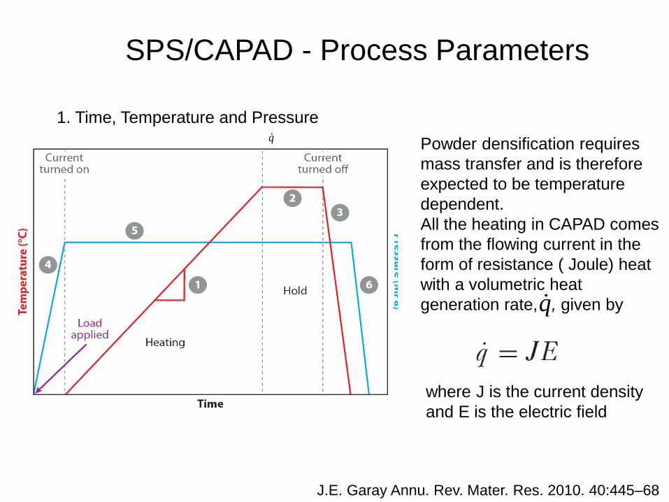
SPS/CAPAD - Process Parameters
1. Time, Temperature and Pressure
Powder densification requires
mass transfer and is therefore
expected to be temperature
dependent.
All the heating in CAPAD comes
from the flowing current in the
form of resistance ( Joule) heat
with a volumetric heat
generation rate, , given by
q
q
where J is the current density
and E is the electric field
J.E. Garay Annu. Rev. Mater. Res. 2010. 40:445–68
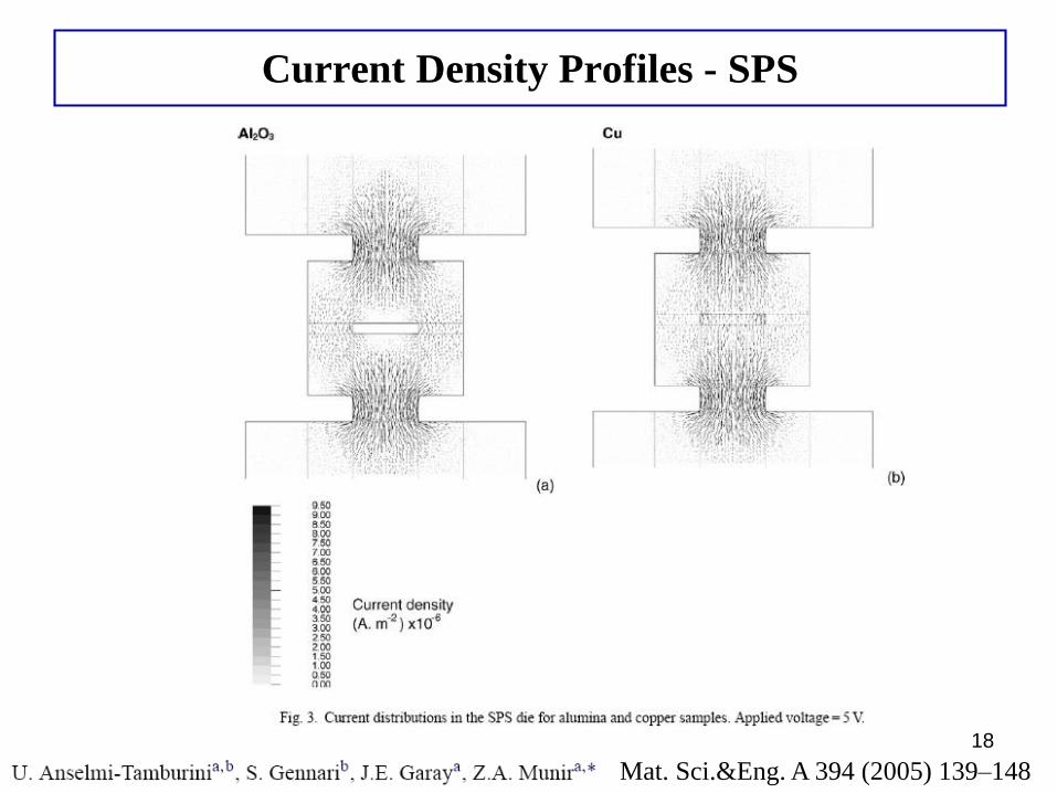
Current Density Profiles - SPS
18
Mat. Sci.&Eng. A 394 (2005) 139–148
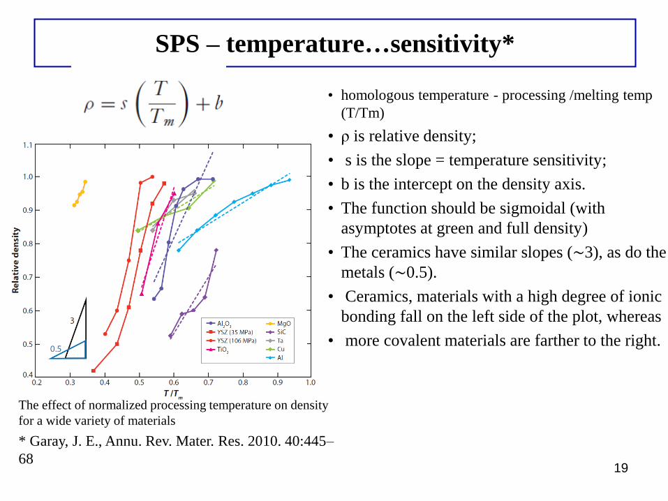
SPS – temperature…sensitivity*
• homologous temperature - processing /melting temp
(T/Tm)
• ρ is relative density;
• s is the slope = temperature sensitivity;
• b is the intercept on the density axis.
• The function should be sigmoidal (with
asymptotes at green and full density)
• The ceramics have similar slopes (∼3), as do the
metals (∼0.5).
• Ceramics, materials with a high degree of ionic
bonding fall on the left side of the plot, whereas
• more covalent materials are farther to the right.
19
The effect of normalized processing temperature on density
for a wide variety of materials
* Garay, J. E., Annu. Rev. Mater. Res. 2010. 40:445–
68
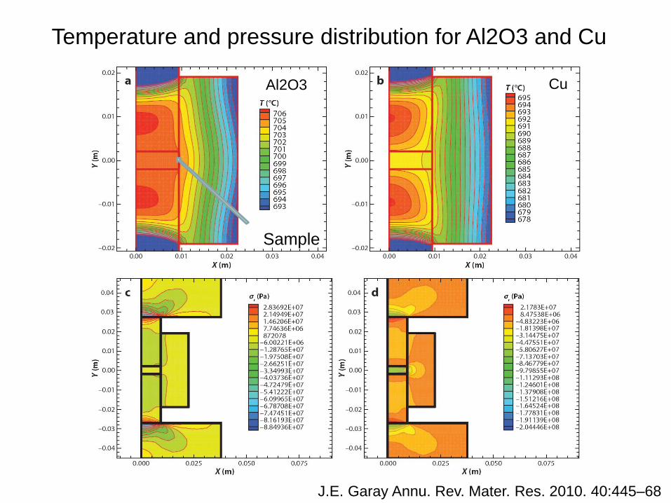
Temperature and pressure distribution for Al2O3 and Cu
J.E. Garay Annu. Rev. Mater. Res. 2010. 40:445–68
Sample
Al2O3 Cu
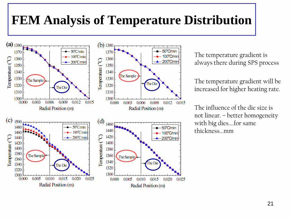
FEM Analysis of Temperature Distribution
The temperature gradient is always there during SPS process
The temperature gradient will be increased for higher heating rate.
The influence of the die size is not linear. – better homogeneity with big dies....for same thickness...mm
21
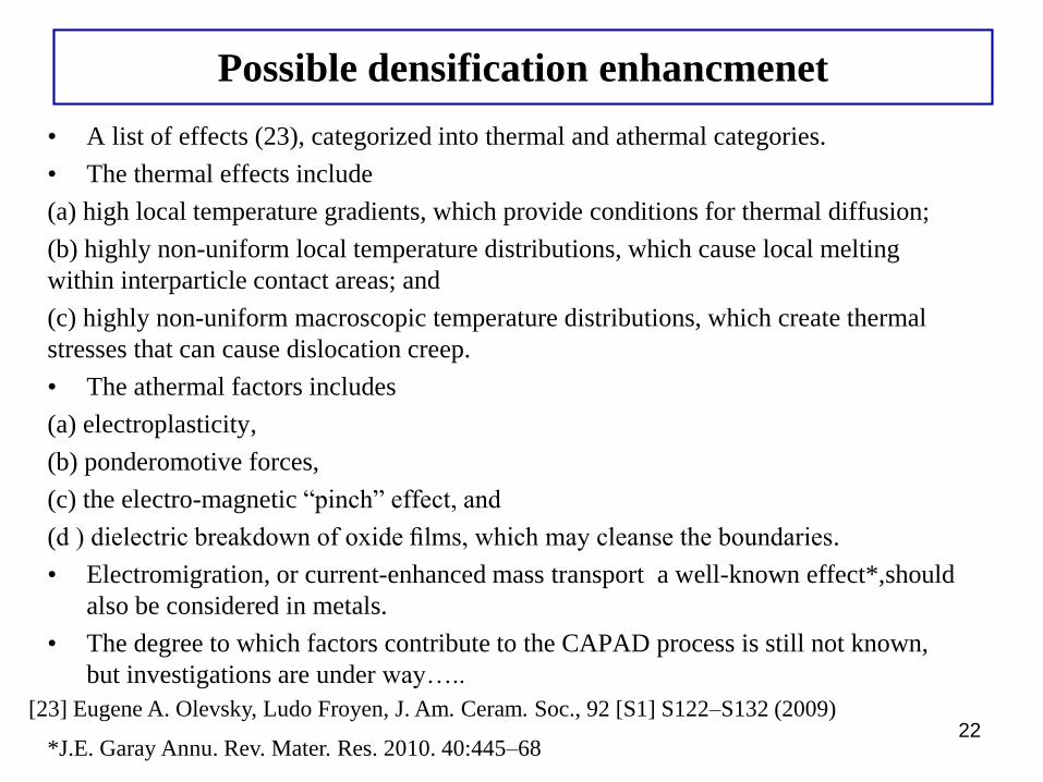
Possible densification enhancmenet
• A list of effects (23), categorized into thermal and athermal categories.
• The thermal effects include
(a) high local temperature gradients, which provide conditions for thermal diffusion;
(b) highly non-uniform local temperature distributions, which cause local melting
within interparticle contact areas; and
(c) highly non-uniform macroscopic temperature distributions, which create thermal
stresses that can cause dislocation creep.
• The athermal factors includes
(a) electroplasticity,
(b) ponderomotive forces,
(c) the electro-magnetic “pinch” effect, and
(d ) dielectric breakdown of oxide films, which may cleanse the boundaries.
• Electromigration, or current-enhanced mass transport a well-known effect*,should
also be considered in metals.
• The degree to which factors contribute to the CAPAD process is still not known,
but investigations are under way…..
22[23] Eugene A. Olevsky, Ludo Froyen, J. Am. Ceram. Soc., 92 [S1] S122–S132 (2009)
*J.E. Garay Annu. Rev. Mater. Res. 2010. 40:445–68
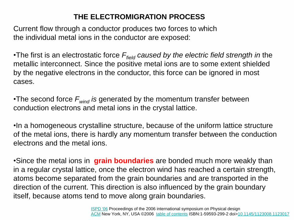
THE ELECTROMIGRATION PROCESS
Current flow through a conductor produces two forces to which
the individual metal ions in the conductor are exposed:
•The first is an electrostatic force Ffield caused by the electric field strength in the
metallic interconnect. Since the positive metal ions are to some extent shielded
by the negative electrons in the conductor, this force can be ignored in most
cases.
•The second force Fwind is generated by the momentum transfer between
conduction electrons and metal ions in the crystal lattice.
•In a homogeneous crystalline structure, because of the uniform lattice structure
of the metal ions, there is hardly any momentum transfer between the conduction
electrons and the metal ions.
•Since the metal ions in grain boundaries are bonded much more weakly than
in a regular crystal lattice, once the electron wind has reached a certain strength,
atoms become separated from the grain boundaries and are transported in the
direction of the current. This direction is also influenced by the grain boundary
itself, because atoms tend to move along grain boundaries.
ISPD '06 Proceedings of the 2006 international symposium on Physical design
ACM New York, NY, USA ©2006 table of contents ISBN:1-59593-299-2 doi>10.1145/1123008.1123017
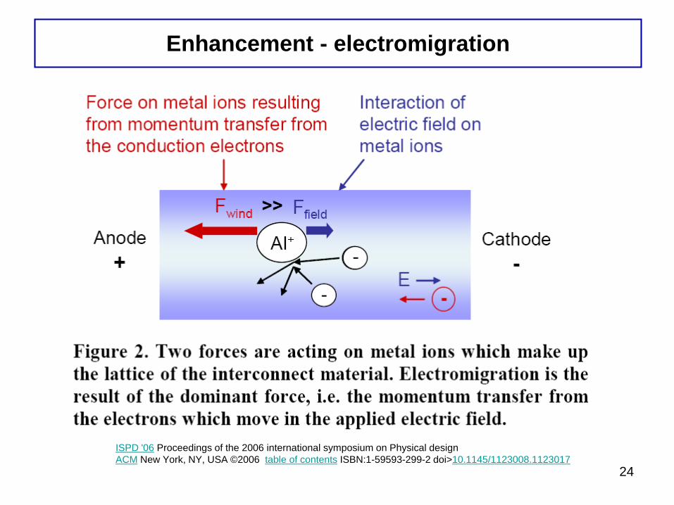
Enhancement - electromigration
24
ISPD '06 Proceedings of the 2006 international symposium on Physical design
ACM New York, NY, USA ©2006 table of contents ISBN:1-59593-299-2 doi>10.1145/1123008.1123017
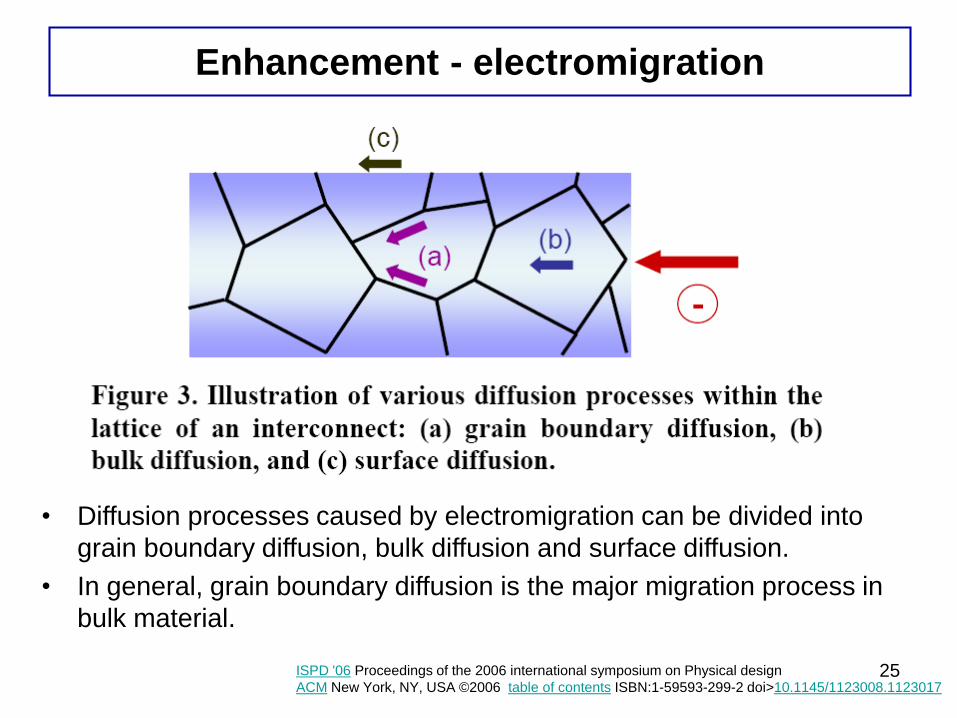
Enhancement - electromigration
• Diffusion processes caused by electromigration can be divided into
grain boundary diffusion, bulk diffusion and surface diffusion.
• In general, grain boundary diffusion is the major migration process in
bulk material.
25ISPD '06 Proceedings of the 2006 international symposium on Physical design
ACM New York, NY, USA ©2006 table of contents ISBN:1-59593-299-2 doi>10.1145/1123008.1123017
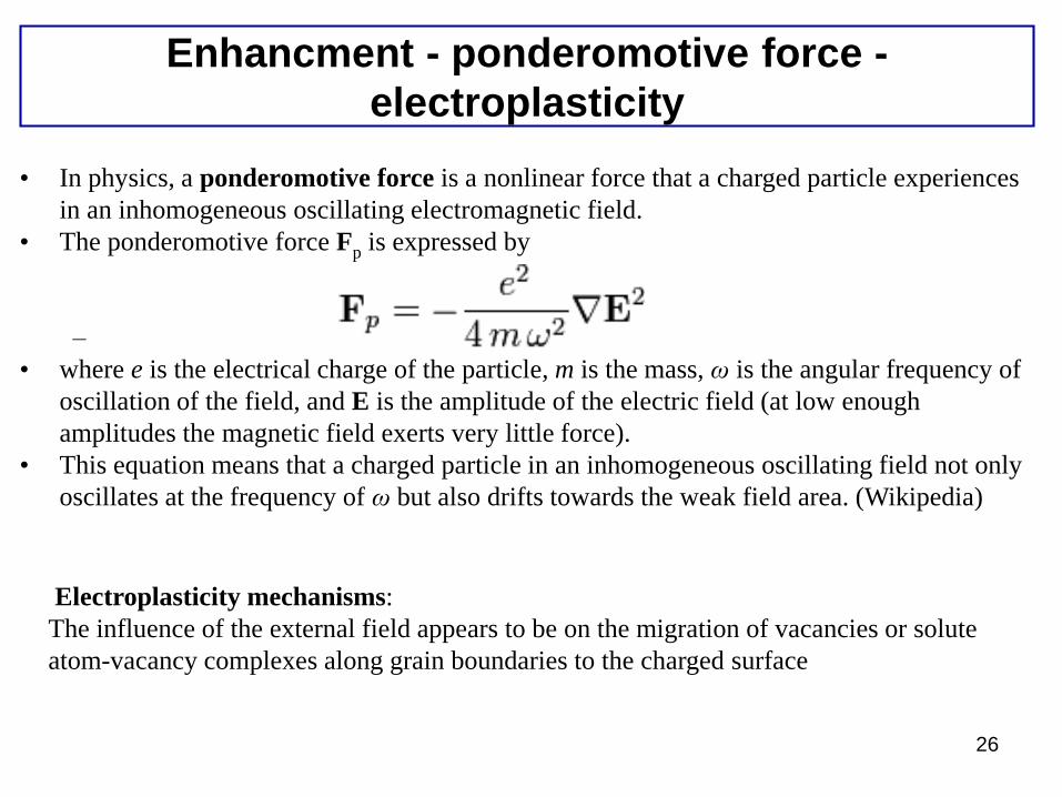
Enhancment - ponderomotive force -
electroplasticity
• In physics, a ponderomotive force is a nonlinear force that a charged particle experiences
in an inhomogeneous oscillating electromagnetic field.
• The ponderomotive force Fp is expressed by
–
• where e is the electrical charge of the particle, m is the mass, ω is the angular frequency of
oscillation of the field, and E is the amplitude of the electric field (at low enough
amplitudes the magnetic field exerts very little force).
• This equation means that a charged particle in an inhomogeneous oscillating field not only
oscillates at the frequency of ω but also drifts towards the weak field area. (Wikipedia)
26
Electroplasticity mechanisms:
The influence of the external field appears to be on the migration of vacancies or solute
atom-vacancy complexes along grain boundaries to the charged surface
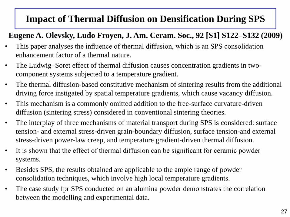
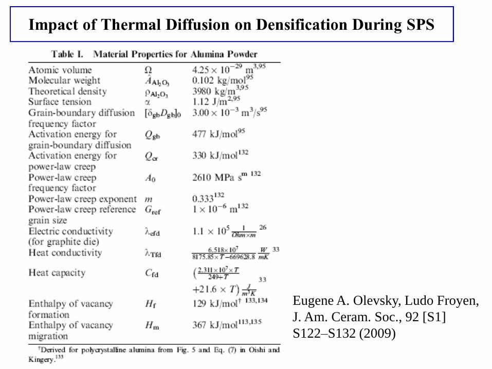
Impact of Thermal Diffusion on Densification During SPS
• This paper analyses the influence of thermal diffusion, which is an SPS consolidation
enhancement factor of a thermal nature.
• The Ludwig–Soret effect of thermal diffusion causes concentration gradients in two-
component systems subjected to a temperature gradient.
• The thermal diffusion-based constitutive mechanism of sintering results from the additional
driving force instigated by spatial temperature gradients, which cause vacancy diffusion.
• This mechanism is a commonly omitted addition to the free-surface curvature-driven
diffusion (sintering stress) considered in conventional sintering theories.
• The interplay of three mechanisms of material transport during SPS is considered: surface
tension- and external stress-driven grain-boundary diffusion, surface tension-and external
stress-driven power-law creep, and temperature gradient-driven thermal diffusion.
• It is shown that the effect of thermal diffusion can be significant for ceramic powder
systems.
• Besides SPS, the results obtained are applicable to the ample range of powder
consolidation techniques, which involve high local temperature gradients.
• The case study fpr SPS conducted on an alumina powder demonstrates the correlation
between the modelling and experimental data.
27
Eugene A. Olevsky, Ludo Froyen, J. Am. Ceram. Soc., 92 [S1] S122–S132 (2009)
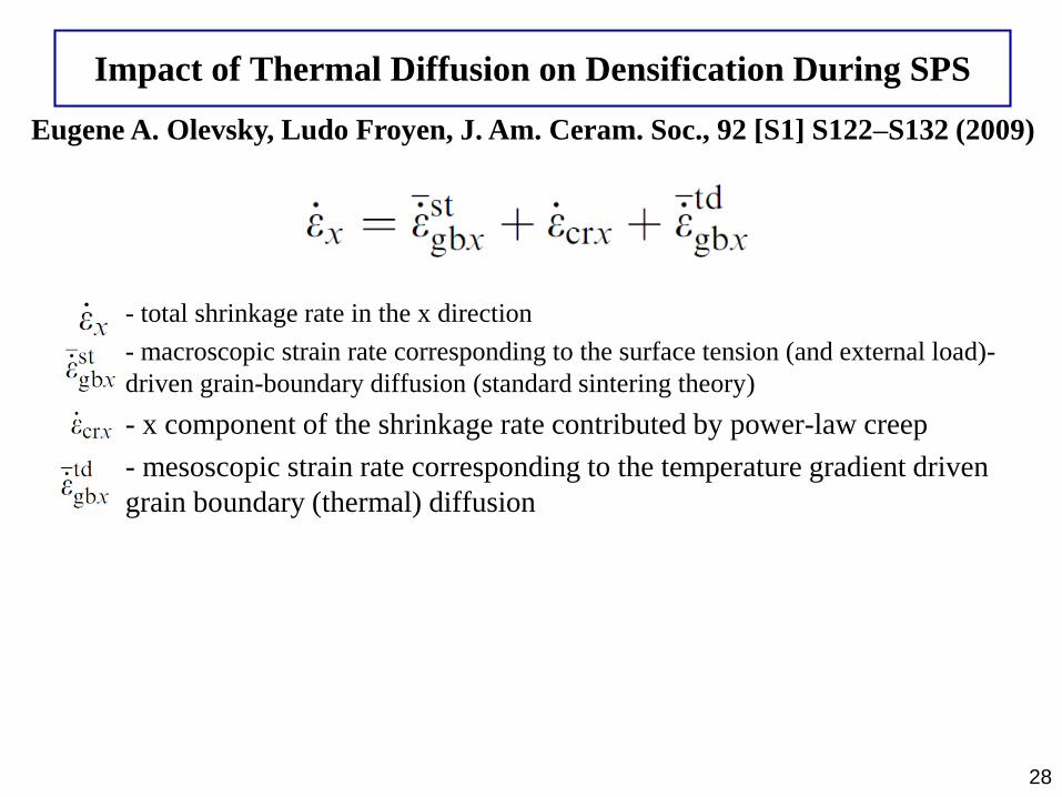
Impact of Thermal Diffusion on Densification During SPS
- total shrinkage rate in the x direction
- macroscopic strain rate corresponding to the surface tension (and external load)-
driven grain-boundary diffusion (standard sintering theory)
- x component of the shrinkage rate contributed by power-law creep
- mesoscopic strain rate corresponding to the temperature gradient driven
grain boundary (thermal) diffusion
28
Eugene A. Olevsky, Ludo Froyen, J. Am. Ceram. Soc., 92 [S1] S122–S132 (2009)
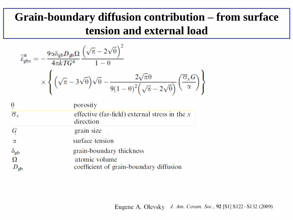
Grain-boundary diffusion contribution – from surface
tension and external load
29
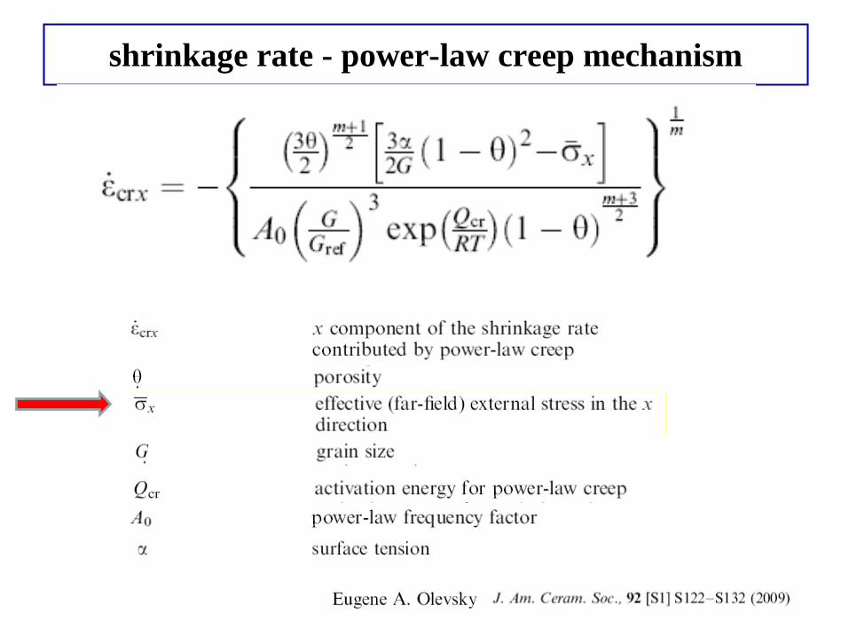
shrinkage rate - power-law creep mechanism
30
Eugene A. Olevsky, Ludo Froyen,
J. Am. Ceram. Soc., 92 [S1]
S122–S132 (2009)
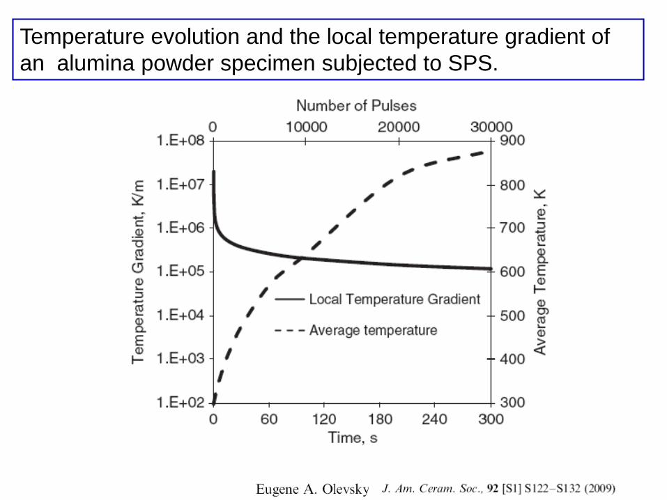
Temperature evolution and the local temperature gradient of
an alumina powder specimen subjected to SPS.
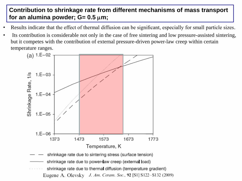
Contribution to shrinkage rate from different mechanisms of mass transport
for an alumina powder; G= 0.5 mm;
• Results indicate that the effect of thermal diffusion can be significant, especially for small particle sizes.
• Its contribution is considerable not only in the case of free sintering and low pressure-assisted sintering,
but it competes with the contribution of external pressure-driven power-law creep within certain
temperature ranges.
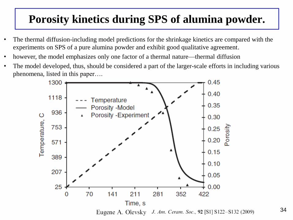
Porosity kinetics during SPS of alumina powder.
34
• The thermal diffusion-including model predictions for the shrinkage kinetics are compared with the
experiments on SPS of a pure alumina powder and exhibit good qualitative agreement.
• however, the model emphasizes only one factor of a thermal nature—thermal diffusion
• The model developed, thus, should be considered a part of the larger-scale efforts in including various
phenomena, listed in this paper….
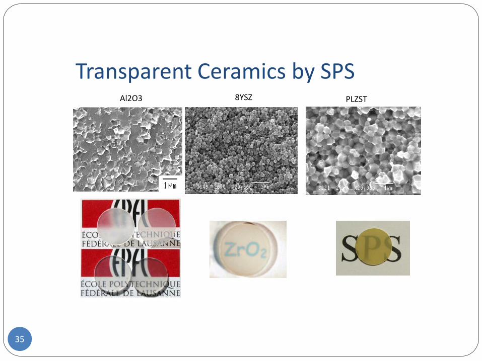
Transparent Ceramics by SPS8YSZ PLZSTAl2O3
35
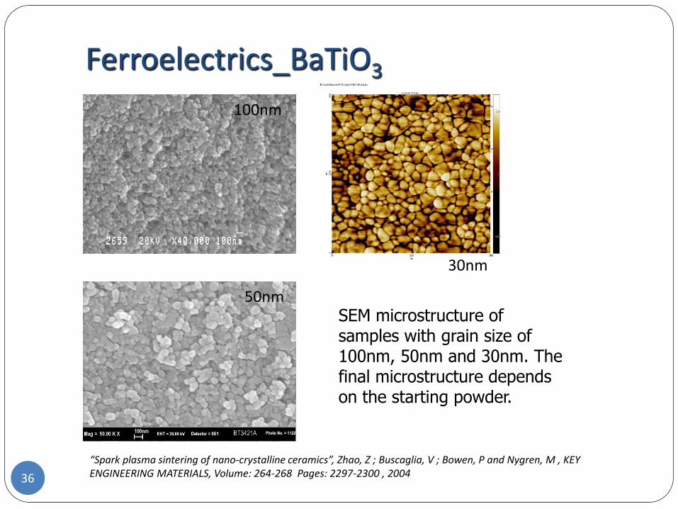
Ferroelectrics_BaTiO3
100nm
50nm
30nm
SEM microstructure of samples with grain size of 100nm, 50nm and 30nm. The final microstructure depends on the starting powder.
“Spark plasma sintering of nano-crystalline ceramics”, Zhao, Z ; Buscaglia, V ; Bowen, P and Nygren, M , KEY ENGINEERING MATERIALS, Volume: 264-268 Pages: 2297-2300 , 200436
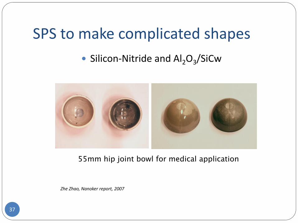
SPS to make complicated shapes
Silicon-Nitride and Al2O3/SiCw
55mm hip joint bowl for medical application
Zhe Zhao, Nanoker report, 2007
37
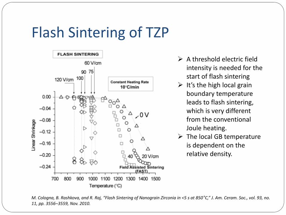
Flash Sintering of TZP
M. Cologna, B. Rashkova, and R. Raj, “Flash Sintering of Nanograin Zirconia in <5 s at 850°C,” J. Am. Ceram. Soc., vol. 93, no. 11, pp. 3556–3559, Nov. 2010.
A threshold electric field intensity is needed for the start of flash sintering
It’s the high local grain boundary temperature leads to flash sintering, which is very different from the conventional Joule heating.
The local GB temperature is dependent on the relative density.
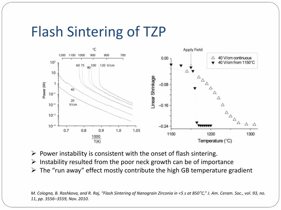
Flash Sintering of TZP
M. Cologna, B. Rashkova, and R. Raj, “Flash Sintering of Nanograin Zirconia in <5 s at 850°C,” J. Am. Ceram. Soc., vol. 93, no. 11, pp. 3556–3559, Nov. 2010.
Power instability is consistent with the onset of flash sintering. Instability resulted from the poor neck growth can be of importance The “run away” effect mostly contribute the high GB temperature gradient
Flashing Sintering Super-Fast processing at relatively lower temperature
For high resistance material, it will not work that efficiently! For example, high purity alumina.
The set-up is simply based on conventional sintering furnaces. This is one advantage for industrial interest.
Not very consistent about the sintering mechanisms.
Need more development for the future applications.
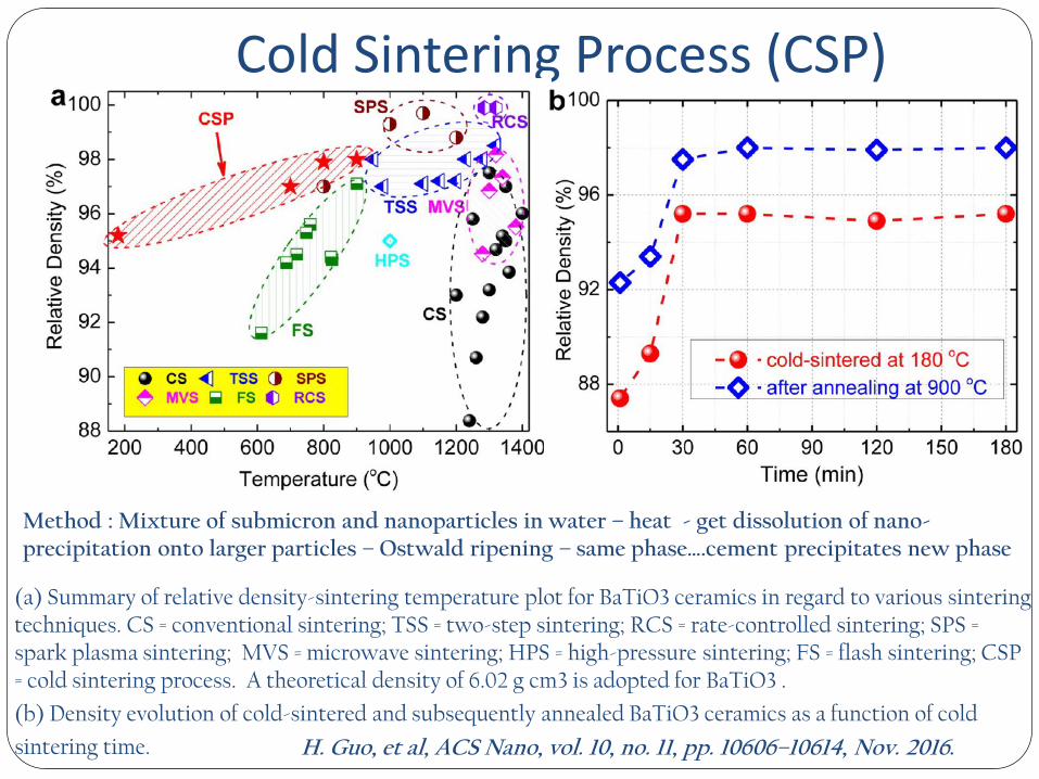
Cold Sintering Process (CSP)
(a) Summary of relative density-sintering temperature plot for BaTiO3 ceramics in regard to various sintering techniques. CS = conventional sintering; TSS = two-step sintering; RCS = rate-controlled sintering; SPS = spark plasma sintering; MVS = microwave sintering; HPS = high-pressure sintering; FS = flash sintering; CSP = cold sintering process. A theoretical density of 6.02 g cm3 is adopted for BaTiO3 .
(b) Density evolution of cold-sintered and subsequently annealed BaTiO3 ceramics as a function of cold
sintering time.
Method : Mixture of submicron and nanoparticles in water – heat - get dissolution of nano-precipitation onto larger particles – Ostwald ripening – same phase….cement precipitates new phase
H. Guo, et al, ACS Nano, vol. 10, no. 11, pp. 10606–10614, Nov. 2016.
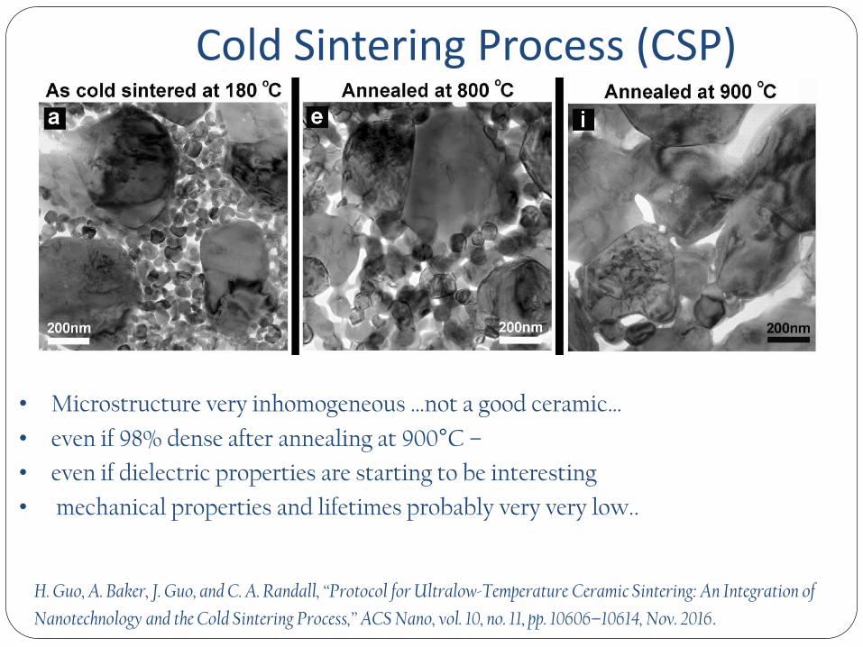
Cold Sintering Process (CSP)
• Microstructure very inhomogeneous …not a good ceramic…
• even if 98% dense after annealing at 900°C –
• even if dielectric properties are starting to be interesting
• mechanical properties and lifetimes probably very very low..
H. Guo, A. Baker, J. Guo, and C. A. Randall, “Protocol for Ultralow-Temperature Ceramic Sintering: An Integration of
Nanotechnology and the Cold Sintering Process,” ACS Nano, vol. 10, no. 11, pp. 10606–10614, Nov. 2016.
Potentials and Problems of CSP In total 16 publications (2017)
90% of publications come from the same research group led by Prof. Clive Randall!
No success of obtaining 100% dense body with any reported ceramics, which can be one issue of using the right powder, but more possibly the method itself cant provide good-enough help in crystal packing and chemical bonding between crystal.
CSP can be good for biomimetic application!
CSP is still a question mark to be called sintering. If it is true, then cement&concrete and ultra-high pressure compaction of metal are already cold-sintering!
Paul Bowen, Michael Stuer
Laboratoire de Technologie des Poudres, Ecole Polytechnique Fédérale de Lausanne, 1015 Lausanne, Switzerland
Fundamental Issues in the Processing of
Transparent Aluminas : From Interparticle Forces to
Dense Transparent Ceramics
Example
45
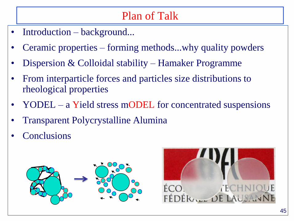
Plan of Talk
• Introduction – background...
• Ceramic properties – forming methods...why quality powders
• Dispersion & Colloidal stability – Hamaker Programme
• From interparticle forces and particles size distributions to rheological properties
• YODEL – a Yield stress mODEL for concentrated suspensions
• Transparent Polycrystalline Alumina
• Conclusions
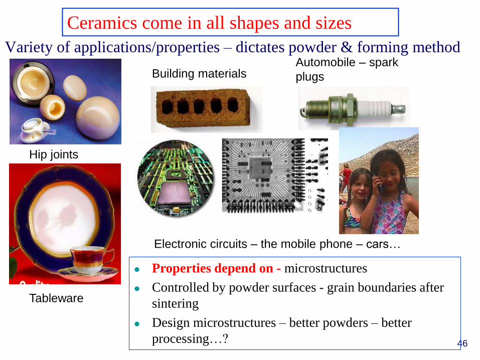
Ceramics come in all shapes and sizes
Variety of applications/properties – dictates powder & forming method
Hip joints
Tableware
Automobile – spark
plugsBuilding materials
Electronic circuits – the mobile phone – cars…
46
Properties depend on - microstructures
Controlled by powder surfaces - grain boundaries after
sintering
Design microstructures – better powders – better
processing…?
Why quality powders - Alpha alumina–effect of agglomerates
Particle size distribution shows small tail of agglomerates – leads to
defects in microstructure and low sintered densities (94%)
99.99
0.1
1
.01 .1 1 5 10 2030 50 7080 9095 99 99.9
AKP50-non-broyéeAKP50-broyée
ES
Dia
mè
tre
(µ
m)
% volume cumulés
47
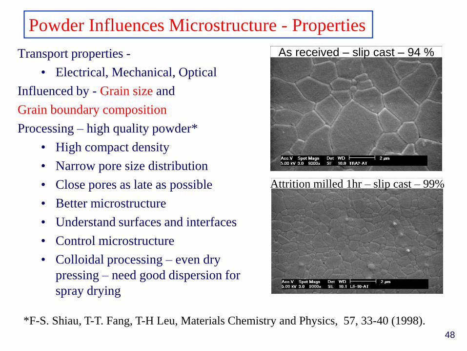
Powder Influences Microstructure - Properties
Transport properties -
• Electrical, Mechanical, Optical
Influenced by - Grain size and
Grain boundary composition
Processing – high quality powder*
• High compact density
• Narrow pore size distribution
• Close pores as late as possible
• Better microstructure
• Understand surfaces and interfaces
• Control microstructure
• Colloidal processing – even dry
pressing – need good dispersion for
spray drying
As received – slip cast – 94 %
Attrition milled 1hr – slip cast – 99%
*F-S. Shiau, T-T. Fang, T-H Leu, Materials Chemistry and Physics, 57, 33-40 (1998).
48
A User Friendly Programme for Interparticle
Interaction Energy Calculations – Hamaker*.
WP8 – Modelling & Simulation
• Uli Aschauer – Easy to use program - http://hamaker.epfl.ch
or
• http://ltp.epfl.ch – Research – Powder Processing – Colloidal
Stability
*U. Aschauer, et al. J. Dispersion Science Technology. 32(4), 470 – 479 (2011)
Steric -polymer adsorption – layer thickness
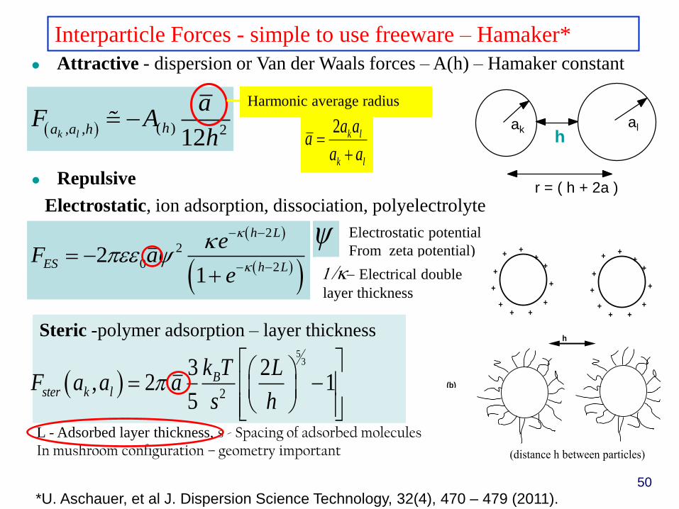
Interparticle Forces - simple to use freeware – Hamaker*
Repulsive
Electrostatic, ion adsorption, dissociation, polyelectrolyte
h
(a)
(b)
++
+
+
++
+
+
+
++
++
+
+
++
+
+
+
++
(distance h between particles)
hak
al
r = ( h + 2a )
*U. Aschauer, et al J. Dispersion Science Technology, 32(4), 470 – 479 (2011).
( ), , 212k lha a h
aF A
h 2 k l
k l
a aa
a a
Harmonic average radius
2
2
0 22
1
h L
ES h L
eF a
e
Electrostatic potential
From zeta potential)
1/ Electrical double
layer thickness
5
3
2
3 2, 2 1
5
Bster k l
k T LF a a a
s h
L - Adsorbed layer thickness, s - Spacing of adsorbed moleculesIn mushroom configuration – geometry important
Attractive - dispersion or Van der Waals forces – A(h) – Hamaker constant
50
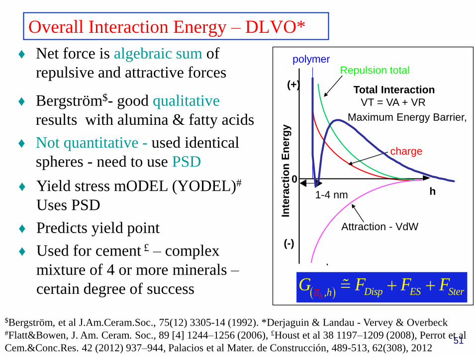
Overall Interaction Energy – DLVO*
♦ Net force is algebraic sum of
repulsive and attractive forces
0
Inte
rac
tio
n E
ne
rgy
charge
polymer
Attraction - VdW
h
(-)
(+)
1-4 nm
Repulsion total
♦ Bergström$- good qualitative
results with alumina & fatty acids
♦ Not quantitative - used identical
spheres - need to use PSD
♦ Yield stress mODEL (YODEL)#
Uses PSD
♦ Predicts yield point
♦ Used for cement £ – complex
mixture of 4 or more minerals –
certain degree of success ,h Disp ES Steha rG F F F
$Bergström, et al J.Am.Ceram.Soc., 75(12) 3305-14 (1992). *Derjaguin & Landau - Vervey & Overbeck #Flatt&Bowen, J. Am. Ceram. Soc., 89 [4] 1244–1256 (2006), £Houst et al 38 1197–1209 (2008), Perrot et al
Cem.&Conc.Res. 42 (2012) 937–944, Palacios et al Mater. de Construcción, 489-513, 62(308), 2012
Total Interaction
VT = VA + VR
Maximum Energy Barrier,
51
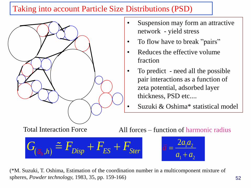
Taking into account Particle Size Distributions (PSD)
• Suspension may form an attractive
network - yield stress
• To flow have to break ”pairs”
• Reduces the effective volume
fraction
• To predict - need all the possible
pair interactions as a function of
zeta potential, adsorbed layer
thickness, PSD etc....
• Suzuki & Oshima* statistical model
,h Disp ES Steha rG F F F
Total Interaction Force
1 2
1 2
2
a a
a aa
All forces – function of harmonic radius
(*M. Suzuki, T. Oshima, Estimation of the coordination number in a multicomponent mixture of
spheres, Powder technology, 1983, 35, pp. 159-166) 52
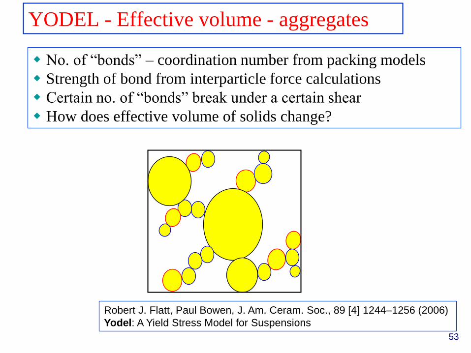
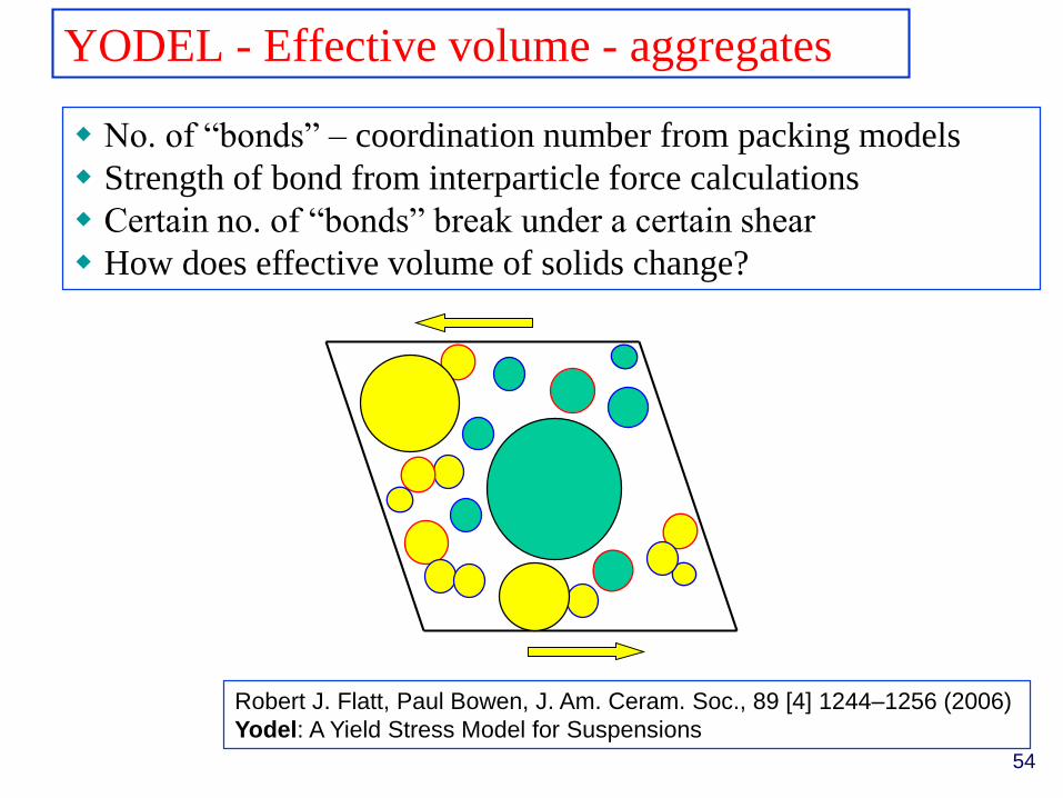
YODEL - Effective volume - aggregates
No. of “bonds” – coordination number from packing models
Strength of bond from interparticle force calculations
Certain no. of “bonds” break under a certain shear
How does effective volume of solids change?
Robert J. Flatt, Paul Bowen, J. Am. Ceram. Soc., 89 [4] 1244–1256 (2006)
Yodel: A Yield Stress Model for Suspensions
53
YODEL - Effective volume - aggregates
No. of “bonds” – coordination number from packing models
Strength of bond from interparticle force calculations
Certain no. of “bonds” break under a certain shear
How does effective volume of solids change?
Robert J. Flatt, Paul Bowen, J. Am. Ceram. Soc., 89 [4] 1244–1256 (2006)
Yodel: A Yield Stress Model for Suspensions
54
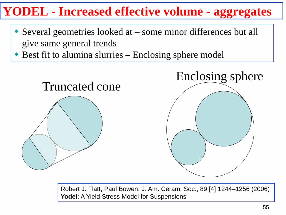
YODEL - Increased effective volume - aggregates
Truncated coneEnclosing sphere
Several geometries looked at – some minor differences but all
give same general trends
Best fit to alumina slurries – Enclosing sphere model
Robert J. Flatt, Paul Bowen, J. Am. Ceram. Soc., 89 [4] 1244–1256 (2006)
Yodel: A Yield Stress Model for Suspensions
55
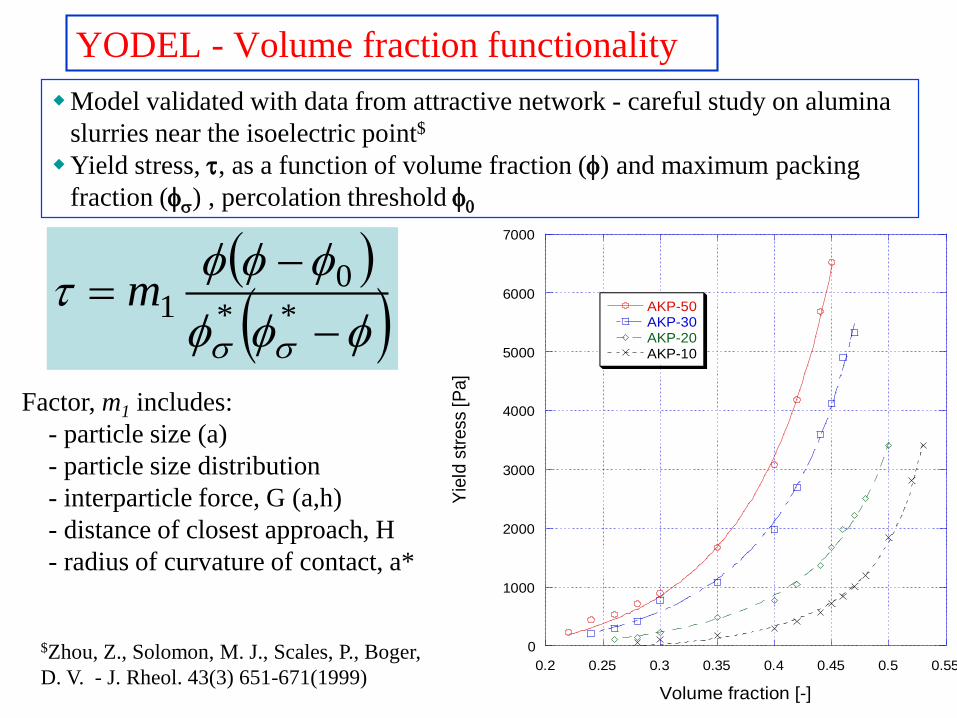
YODEL - Volume fraction functionality
**
01m
Factor, m1 includes:
- particle size (a)
- particle size distribution
- interparticle force, G (a,h)
- distance of closest approach, H
- radius of curvature of contact, a*
0
1000
2000
3000
4000
5000
6000
7000
0.2 0.25 0.3 0.35 0.4 0.45 0.5 0.55
AKP-50AKP-30AKP-20AKP-10
Yie
ld s
tress
[Pa]
Volume fraction [-]
Model validated with data from attractive network - careful study on alumina
slurries near the isoelectric point$
Yield stress, , as a function of volume fraction () and maximum packing
fraction () , percolation threshold 0
$Zhou, Z., Solomon, M. J., Scales, P., Boger,
D. V. - J. Rheol. 43(3) 651-671(1999)
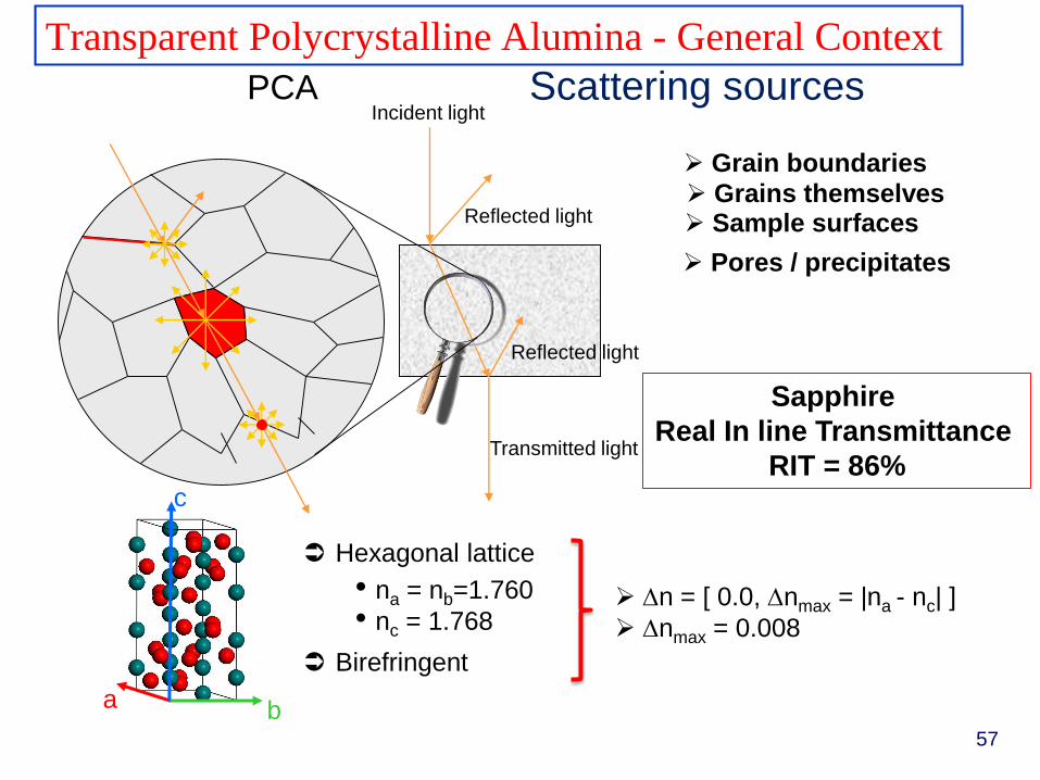
Pores / precipitates
Grains themselves
Transparent Polycrystalline Alumina - General Context
Scattering sources
Sample surfaces
Incident light
Reflected light
Transmitted light
Reflected light
Grain boundaries
a b
c
Hexagonal lattice
• na = nb=1.760
• nc = 1.768
Birefringent
n = [ 0.0, nmax = |na - nc| ]
nmax = 0.008
PCA
57
Sapphire
Real In line Transmittance
RIT = 86%
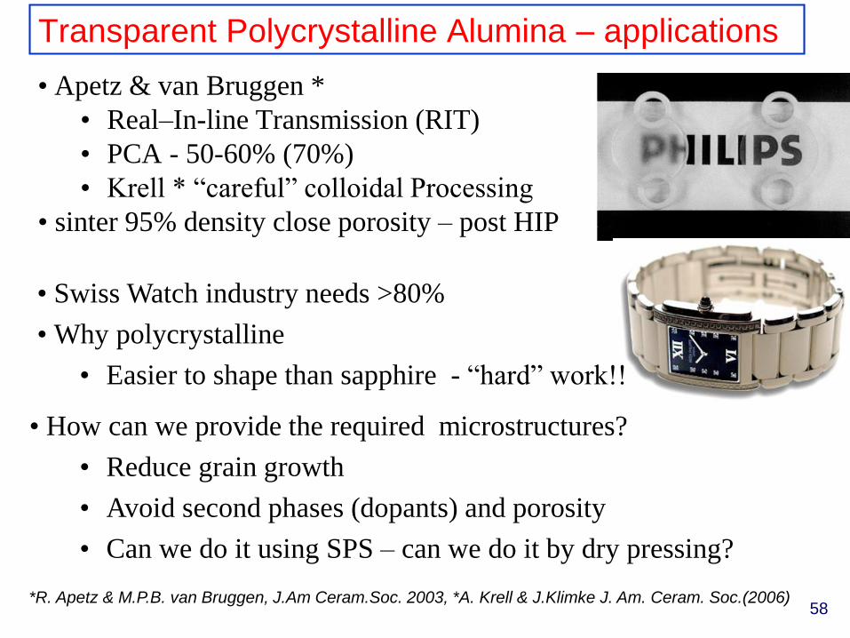
Transparent Polycrystalline Alumina – applications
• Apetz & van Bruggen *
• Real–In-line Transmission (RIT)
• PCA - 50-60% (70%)
• Krell * “careful” colloidal Processing
• sinter 95% density close porosity – post HIP
*R. Apetz & M.P.B. van Bruggen, J.Am Ceram.Soc. 2003, *A. Krell & J.Klimke J. Am. Ceram. Soc.(2006)
• Swiss Watch industry needs >80%
• Why polycrystalline
• Easier to shape than sapphire - “hard” work!!
• How can we provide the required microstructures?
• Reduce grain growth
• Avoid second phases (dopants) and porosity
• Can we do it using SPS – can we do it by dry pressing?
58
0
10
20
30
40
50
60
70
80
90
0.0 0.5 1.0 1.5 2.0 2.5 3.0 3.5 4.0
RIT
[%
]
grain size [mm] Diameter
Δn=0.005 porosity: 0.00% vol.
Δn=0.004 porosity: 0.00% vol.
Δn=0.005 porosity: 0.01% vol.
Δn=0.005 porosity: 0.05% vol.
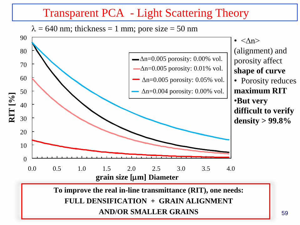
Transparent PCA - Light Scattering Theory
= 640 nm; thickness = 1 mm; pore size = 50 nm
• <∆n>
(alignment) and
porosity affect
shape of curve
• Porosity reduces
maximum RIT
•But very
difficult to verify
density > 99.8%
To improve the real in-line transmittance (RIT), one needs:
FULL DENSIFICATION + GRAIN ALIGNMENT
AND/OR SMALLER GRAINS 59
Pri
vate
th
esis
def
ense
, 20
12.
60
1. Introduction 2. Overview 3. Coloration 4. Doping 5. Conclusions
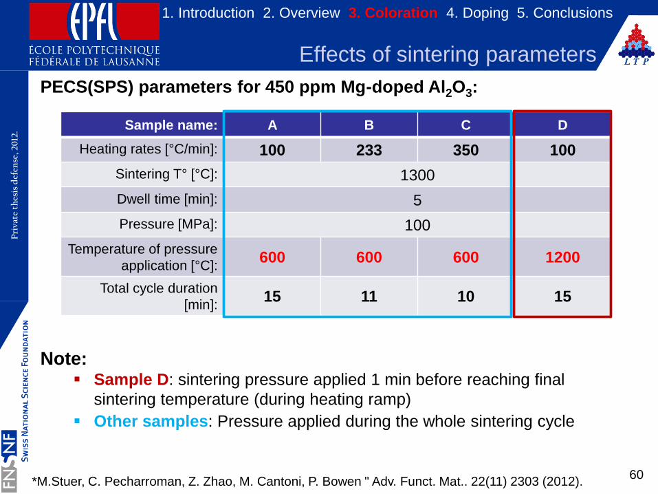
PECS(SPS) parameters for 450 ppm Mg-doped Al2O3:
Note: Sample D: sintering pressure applied 1 min before reaching final
sintering temperature (during heating ramp)
Other samples: Pressure applied during the whole sintering cycle
Effects of sintering parameters
Sample name: A B C D
Heating rates [°C/min]: 100 233 350 100
Sintering T° [°C]: 1300
Dwell time [min]: 5
Pressure [MPa]: 100
Temperature of pressure
application [°C]:600 600 600 1200
Total cycle duration
[min]:15 11 10 15
*M.Stuer, C. Pecharroman, Z. Zhao, M. Cantoni, P. Bowen " Adv. Funct. Mat.. 22(11) 2303 (2012).
Pri
vate
th
esis
def
ense
, 20
12.
61
1. Introduction 2. Overview 3. Coloration 4. Doping 5. Conclusions
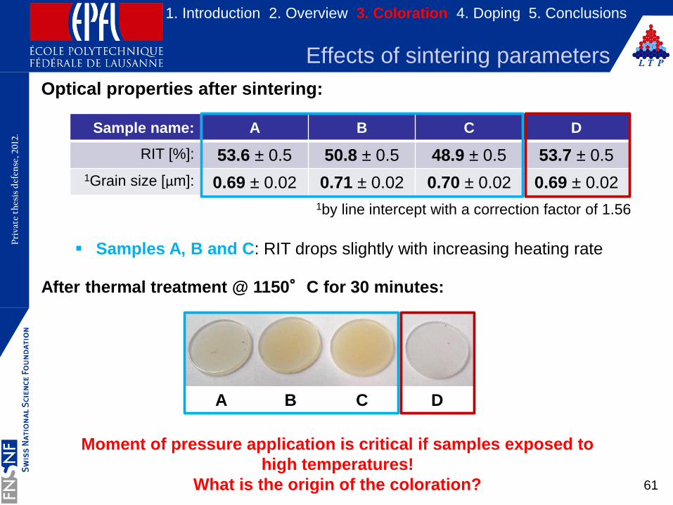
Optical properties after sintering:
Samples A, B and C: RIT drops slightly with increasing heating rate
After thermal treatment @ 1150°C for 30 minutes:
Moment of pressure application is critical if samples exposed to
high temperatures!
What is the origin of the coloration?
Effects of sintering parameters
Sample name: A B C D
RIT [%]: 53.6 ± 0.5 50.8 ± 0.5 48.9 ± 0.5 53.7 ± 0.5
1Grain size [µm]: 0.69 ± 0.02 0.71 ± 0.02 0.70 ± 0.02 0.69 ± 0.02
1by line intercept with a correction factor of 1.56
A B C D
Pri
vate
th
esis
def
ense
, 20
12.
62
1. Introduction 2. Overview 3. Coloration 4. Doping 5. Conclusions
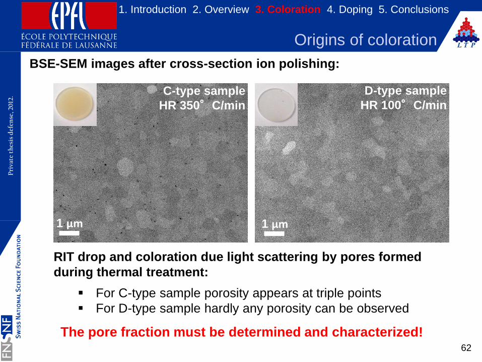
BSE-SEM images after cross-section ion polishing:
RIT drop and coloration due light scattering by pores formed
during thermal treatment:
For C-type sample porosity appears at triple points
For D-type sample hardly any porosity can be observed
The pore fraction must be determined and characterized!
Origins of coloration
1 µm 1 µm
C-type sample
HR 350°C/min
D-type sample
HR 100°C/min
Pri
vate
th
esis
def
ense
, 20
12.
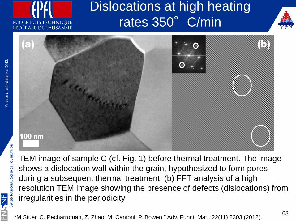
TEM image of sample C (cf. Fig. 1) before thermal treatment. The image
shows a dislocation wall within the grain, hypothesized to form pores
during a subsequent thermal treatment. (b) FFT analysis of a high
resolution TEM image showing the presence of defects (dislocations) from
irregularities in the periodicity
Dislocations at high heating
rates 350°C/min
63*M.Stuer, C. Pecharroman, Z. Zhao, M. Cantoni, P. Bowen " Adv. Funct. Mat.. 22(11) 2303 (2012).
Pri
vate
th
esis
def
ense
, 20
12.
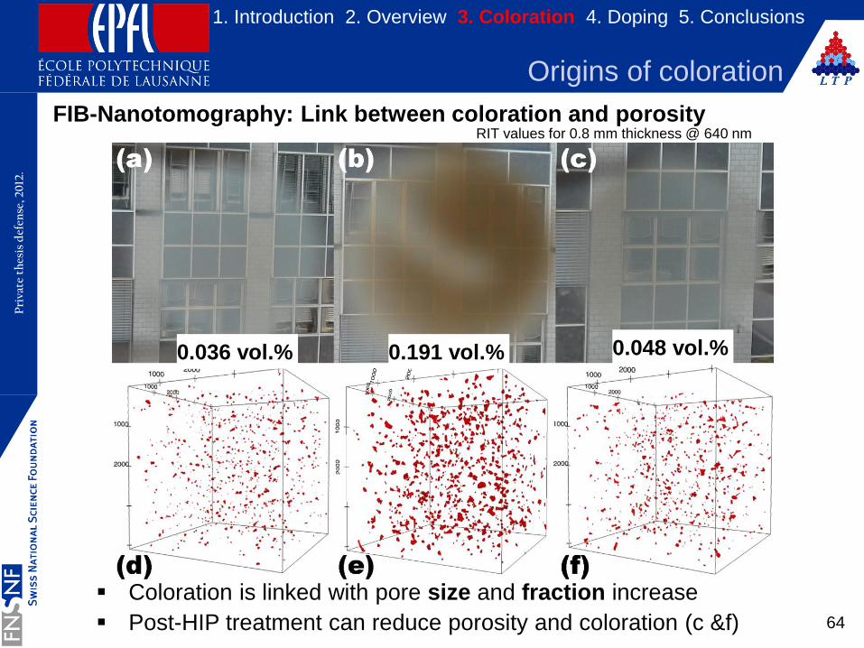
FIB-Nanotomography: Link between coloration and porosity
Coloration is linked with pore size and fraction increase
Post-HIP treatment can reduce porosity and coloration (c &f) 64
1. Introduction 2. Overview 3. Coloration 4. Doping 5. Conclusions
Origins of coloration
RIT values for 0.8 mm thickness @ 640 nm
4.11µm x 4.11µm x 4.11µm extracts
0.191 vol.% 0.048 vol.%
0.036 vol.% 0.191 vol.% 0.048 vol.%
65
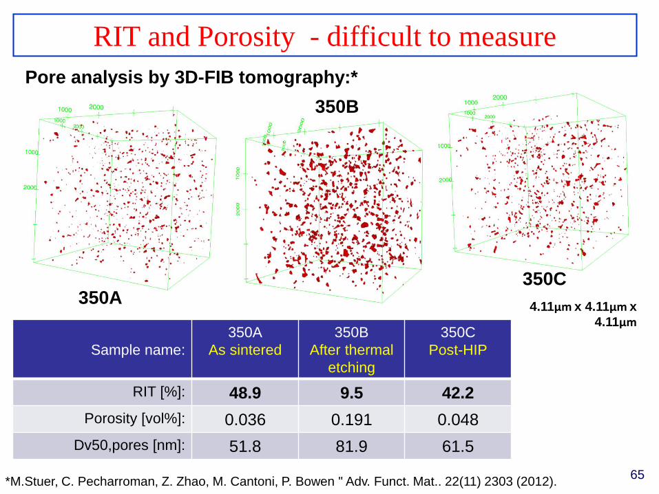
RIT and Porosity - difficult to measure
Pore analysis by 3D-FIB tomography:*
Sample name:
350A
As sintered
350B
After thermal
etching
350C
Post-HIP
RIT [%]: 48.9 9.5 42.2
Porosity [vol%]: 0.036 0.191 0.048
Dv50,pores [nm]: 51.8 81.9 61.5
350A
350B
350C
4.11µm x 4.11µm x
4.11µm
*M.Stuer, C. Pecharroman, Z. Zhao, M. Cantoni, P. Bowen " Adv. Funct. Mat.. 22(11) 2303 (2012).
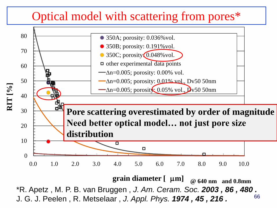
66*R. Apetz , M. P. B. van Bruggen , J. Am. Ceram. Soc. 2003 , 86 , 480 .
J. G. J. Peelen , R. Metselaar , J. Appl. Phys. 1974 , 45 , 216 .
0
10
20
30
40
50
60
70
80
0.0 1.0 2.0 3.0 4.0 5.0 6.0 7.0 8.0 9.0 10.0
RIT
[%
]
grain diameter [ mm]
350A; porosity: 0.036%vol.
350B; porosity: 0.191%vol.
350C; porosity: 0.048%vol.
other experimental data points
n=0.005; porosity: 0.00% vol.
n=0.005; porosity: 0.01% vol., Dv50 50nm
n=0.005; porosity: 0.05% vol., Dv50 50nm
@ 640 nm and 0.8mm
Pore scattering overestimated by order of magnitude
Need better optical model… not just pore size
distribution
Optical model with scattering from pores*
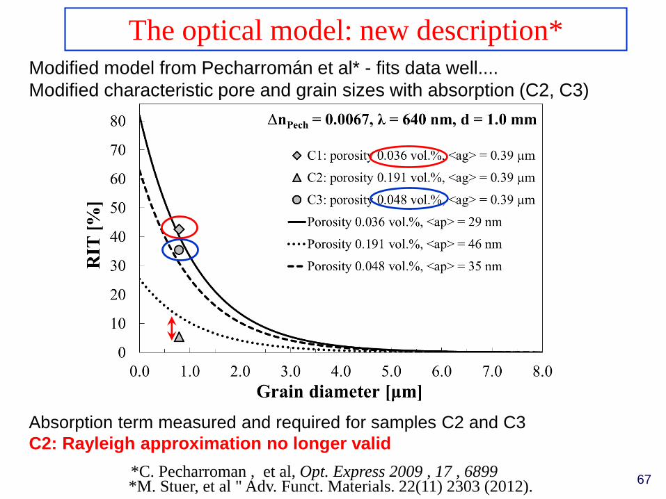
Modified model from Pecharromán et al* - fits data well....
Modified characteristic pore and grain sizes with absorption (C2, C3)
Absorption term measured and required for samples C2 and C3
C2: Rayleigh approximation no longer valid
67
The optical model: new description*
*C. Pecharroman , et al, Opt. Express 2009 , 17 , 6899*M. Stuer, et al " Adv. Funct. Materials. 22(11) 2303 (2012).
68
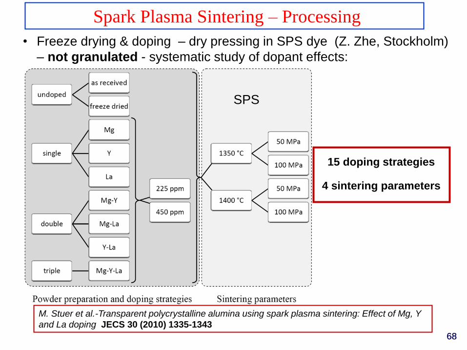
Spark Plasma Sintering – Processing
• Freeze drying & doping – dry pressing in SPS dye (Z. Zhe, Stockholm)
– not granulated - systematic study of dopant effects:
68
15 doping strategies
4 sintering parameters
M. Stuer et al.-Transparent polycrystalline alumina using spark plasma sintering: Effect of Mg, Y
and La doping JECS 30 (2010) 1335-1343
SPS
69
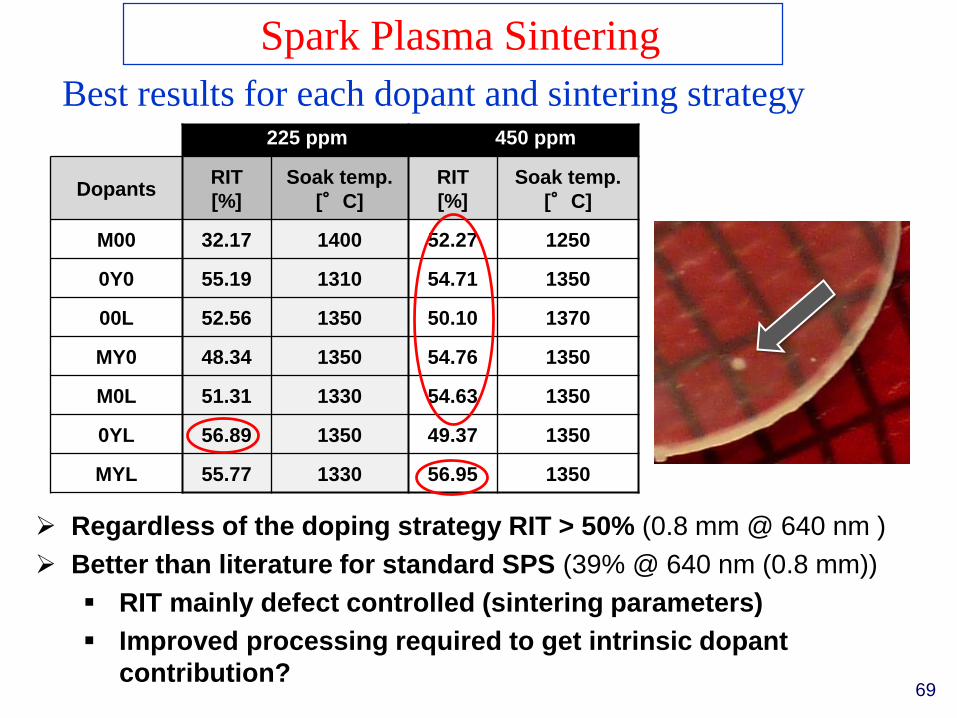
Spark Plasma Sintering
Best results for each dopant and sintering strategy
100 MPa
225 ppm 450 ppm
DopantsRIT
[%]
Soak temp.
[°C]
RIT
[%]
Soak temp.
[°C]
M00 32.17 1400 52.27 1250
0Y0 55.19 1310 54.71 1350
00L 52.56 1350 50.10 1370
MY0 48.34 1350 54.76 1350
M0L 51.31 1330 54.63 1350
0YL 56.89 1350 49.37 1350
MYL 55.77 1330 56.95 1350
Regardless of the doping strategy RIT > 50% (0.8 mm @ 640 nm )
Better than literature for standard SPS (39% @ 640 nm (0.8 mm))
RIT mainly defect controlled (sintering parameters)
Improved processing required to get intrinsic dopant
contribution?
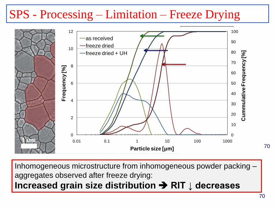
SPS - Processing – Limitation – Freeze Drying
Inhomogeneous microstructure from inhomogeneous powder packing –
aggregates observed after freeze drying:
Increased grain size distribution RIT ↓ decreases
70
100 MPa
0
10
20
30
40
50
60
70
80
90
100
0
2
4
6
8
10
12
0.01 0.1 1 10 100 1000
Cu
mm
ula
tive F
req
uen
cy [%
]
Fre
qu
en
cy [%
]
Particle size [μm]
as received
freeze dried
freeze dried + UH
70
71
100 MPaSyringe pump
VUp to 2kV
Piezo
Power
Generator
Up to 2000 Hz
100 μm tip
Vibrating
membrane
Charged ring
Liquid N2 bath
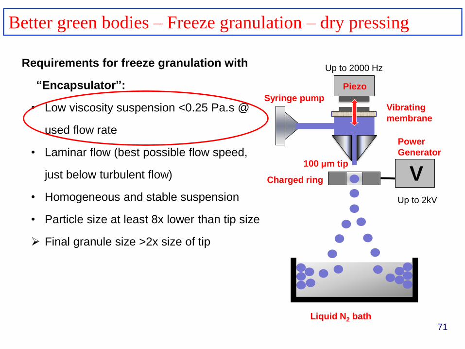
Better green bodies – Freeze granulation – dry pressing
Requirements for freeze granulation with
“Encapsulator”:
• Low viscosity suspension <0.25 Pa.s @
used flow rate
• Laminar flow (best possible flow speed,
just below turbulent flow)
• Homogeneous and stable suspension
• Particle size at least 8x lower than tip size
Final granule size >2x size of tip
72
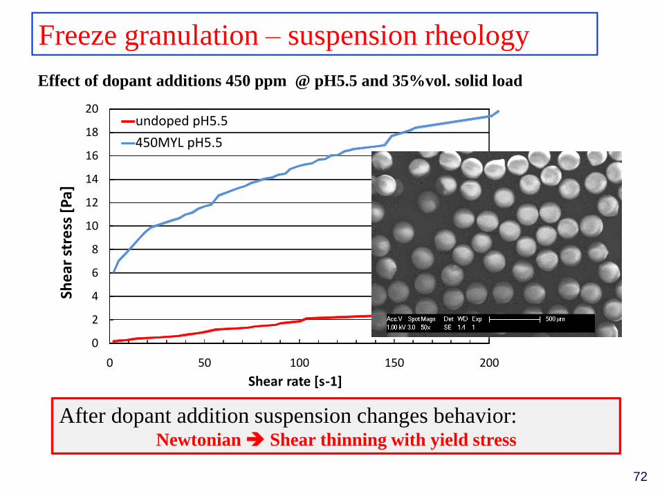
Freeze granulation – suspension rheology
Effect of dopant additions 450 ppm @ pH5.5 and 35%vol. solid load
After dopant addition suspension changes behavior:Newtonian Shear thinning with yield stress
0
2
4
6
8
10
12
14
16
18
20
0 50 100 150 200
She
arst
ress
[P
a]
Shear rate [s-1]
undoped pH5.5
450MYL pH5.5
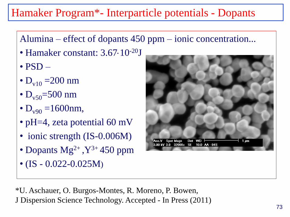
Hamaker Program*- Interparticle potentials - Dopants
Alumina – effect of dopants 450 ppm – ionic concentration...
• Hamaker constant: 3.6710-20J
• PSD –
• Dv10 =200 nm
• Dv50=500 nm
• Dv90 =1600nm,
• pH=4, zeta potential 60 mV
• ionic strength (IS-0.006M)
• Dopants Mg2+ ,Y3+ 450 ppm
• (IS - 0.022-0.025M)
*U. Aschauer, O. Burgos-Montes, R. Moreno, P. Bowen,
J Dispersion Science Technology. Accepted - In Press (2011)73
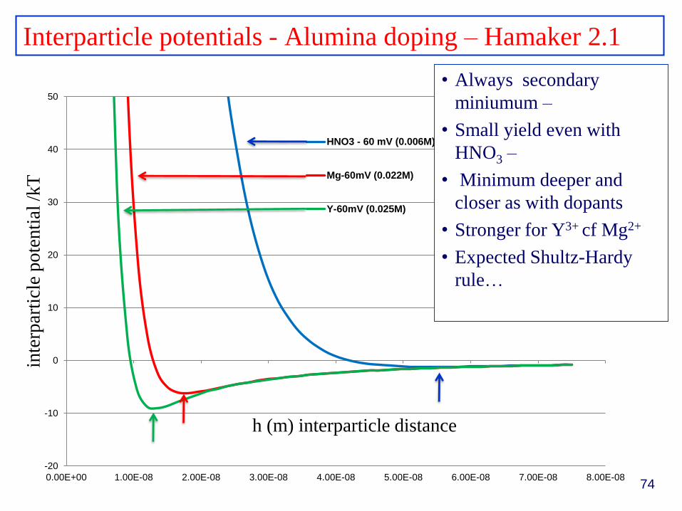
Interparticle potentials - Alumina doping – Hamaker 2.1
74
-20
-10
0
10
20
30
40
50
0.00E+00 1.00E-08 2.00E-08 3.00E-08 4.00E-08 5.00E-08 6.00E-08 7.00E-08 8.00E-08
HNO3 - 60 mV (0.006M)
Mg-60mV (0.022M)
Y-60mV (0.025M)
• Always secondary
miniumum –
• Small yield even with
HNO3 –
• Minimum deeper and
closer as with dopants
• Stronger for Y3+ cf Mg2+
• Expected Shultz-Hardy
rule…
h (m) interparticle distance
inte
rpar
ticl
epo
tenti
al/k
T
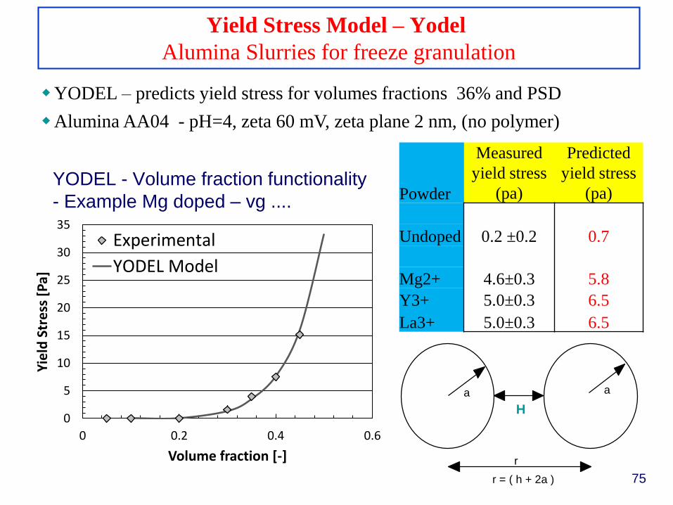
Yield Stress Model – Yodel
Alumina Slurries for freeze granulation
YODEL – predicts yield stress for volumes fractions 36% and PSD
Alumina AA04 - pH=4, zeta 60 mV, zeta plane 2 nm, (no polymer)
Powder
Measured
yield stress
(pa)
Predicted
yield stress
(pa)
Undoped 0.2 ±0.2 0.7
Mg2+ 4.6±0.3 5.8
Y3+ 5.0±0.3 6.5
La3+ 5.0±0.3 6.5
H
a a
r
r = ( h + 2a )
0
5
10
15
20
25
30
35
0 0.2 0.4 0.6
Yie
ld S
tre
ss [
Pa]
Volume fraction [-]
Experimental
YODEL Model
YODEL - Volume fraction functionality
- Example Mg doped – vg ....
75
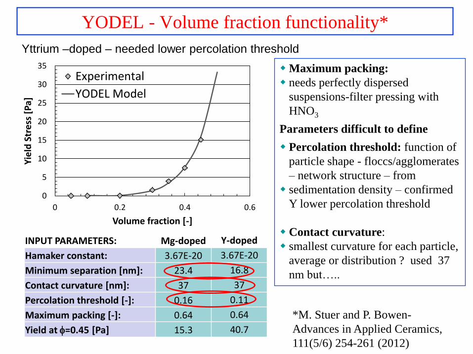
YODEL - Volume fraction functionality*
Maximum packing:
needs perfectly dispersed
suspensions-filter pressing with
HNO3
Parameters difficult to define
Percolation threshold: function of
particle shape - floccs/agglomerates
– network structure – from
sedimentation density – confirmed
Y lower percolation threshold
Contact curvature:
smallest curvature for each particle,
average or distribution ? used 37
nm but…..
INPUT PARAMETERS: Mg-doped Y-doped
Hamaker constant: 3.67E-20 3.67E-20
Minimum separation [nm]: 23.4 16.8
Contact curvature [nm]: 37 37
Percolation threshold [-]: 0.16 0.11
Maximum packing [-]: 0.64 0.64
Yield at =0.45 [Pa] 15.3 40.7
Yttrium –doped – needed lower percolation threshold
0
5
10
15
20
25
30
35
0 0.2 0.4 0.6
Yie
ld S
tre
ss [
Pa]
Volume fraction [-]
Experimental
YODEL Model
*M. Stuer and P. Bowen-
Advances in Applied Ceramics,
111(5/6) 254-261 (2012)
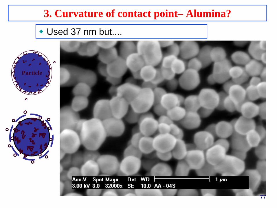
3. Curvature of contact point– Alumina?
EUROMAT 2007
Nürnberg, 10 – 14 September
Particle
-
-
-
--
-
--
-
-
--
-
Used 37 nm but....
77
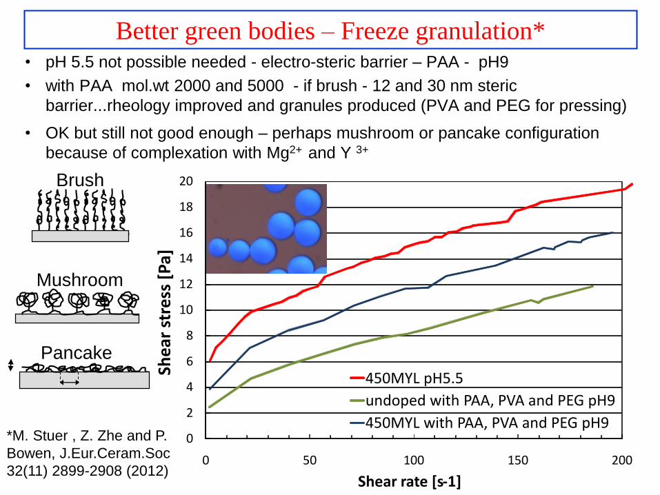
Better green bodies – Freeze granulation*• pH 5.5 not possible needed - electro-steric barrier – PAA - pH9
• with PAA mol.wt 2000 and 5000 - if brush - 12 and 30 nm steric
barrier...rheology improved and granules produced (PVA and PEG for pressing)
• OK but still not good enough – perhaps mushroom or pancake configuration
because of complexation with Mg2+ and Y 3+
78
0
2
4
6
8
10
12
14
16
18
20
0 50 100 150 200
She
arst
ress
[P
a]
Shear rate [s-1]
450MYL pH5.5
undoped with PAA, PVA and PEG pH9
450MYL with PAA, PVA and PEG pH9*M. Stuer , Z. Zhe and P.
Bowen, J.Eur.Ceram.Soc
32(11) 2899-2908 (2012)
Pancake
Brush
Mushroom
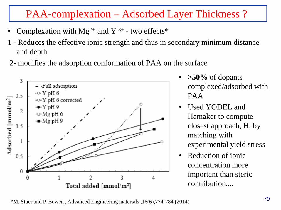
PAA-complexation – Adsorbed Layer Thickness ?
• Complexation with Mg2+ and Y 3+ - two effects*
1 - Reduces the effective ionic strength and thus in secondary minimum distance
and depth
2- modifies the adsorption conformation of PAA on the surface
• >50% of dopants
complexed/adsorbed with
PAA
• Used YODEL and
Hamaker to compute
closest approach, H, by
matching with
experimental yield stress
• Reduction of ionic
concentration more
important than steric
contribution....
79*M. Stuer and P. Bowen , Advanced Engineering materials ,16(6),774-784 (2014)
– Green body densities 56%
– SPS > 99.9% dense……
– RITs - 53%* - slightly lower than freeze dried
– Improvements still needed...suspension need higher solids load
– But successful use of “standard” processing for SPS – simpler
than slip-casting ....easier and cheaper for industrial application
– Next step apply same process to finer powders, Dv50- 130nm –
dispersion still challenging.....
– Best result so far 65% RIT at 150 MPa ......>70% soon.
– ....in fact ..........
Results – Freeze Granulation - dry pressing*
80*M. Stuer , Z. Zhe and P. Bowen, J.Eur.Ceram.Soc 32(11) 2899 (2012).
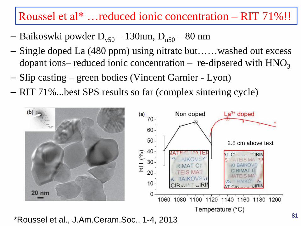
– Baikoswki powder Dv50 – 130nm, Dn50 – 80 nm
– Single doped La (480 ppm) using nitrate but……washed out excess
dopant ions– reduced ionic concentration – re-dipsered with HNO3
– Slip casting – green bodies (Vincent Garnier - Lyon)
– RIT 71%...best SPS results so far (complex sintering cycle)
Roussel et al* …reduced ionic concentration – RIT 71%!!
81*Roussel et al., J.Am.Ceram.Soc., 1-4, 2013
2.8 cm above text
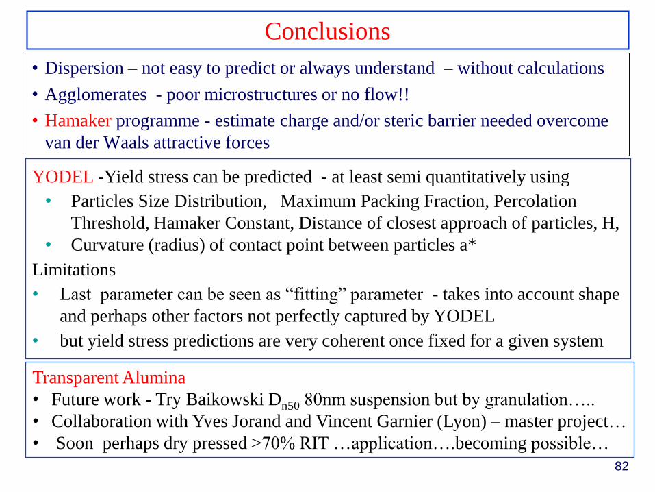
Conclusions
82
• Dispersion – not easy to predict or always understand – without calculations
• Agglomerates - poor microstructures or no flow!!
• Hamaker programme - estimate charge and/or steric barrier needed overcome
van der Waals attractive forces
YODEL -Yield stress can be predicted - at least semi quantitatively using
• Particles Size Distribution, Maximum Packing Fraction, Percolation
Threshold, Hamaker Constant, Distance of closest approach of particles, H,
• Curvature (radius) of contact point between particles a*
Limitations
• Last parameter can be seen as “fitting” parameter - takes into account shape
and perhaps other factors not perfectly captured by YODEL
• but yield stress predictions are very coherent once fixed for a given system
Transparent Alumina
• Future work - Try Baikowski Dn50 80nm suspension but by granulation…..
• Collaboration with Yves Jorand and Vincent Garnier (Lyon) – master project…
• Soon perhaps dry pressed >70% RIT …application….becoming possible…
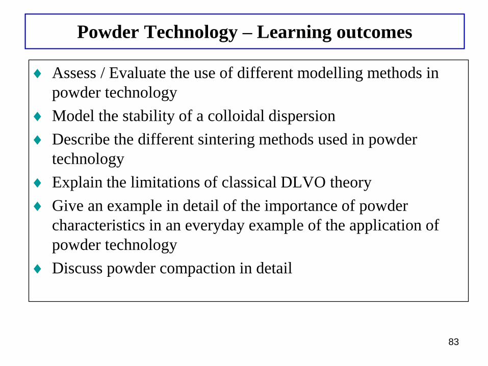
Powder Technology – Learning outcomes
83
Assess / Evaluate the use of different modelling methods in
powder technology
Model the stability of a colloidal dispersion
Describe the different sintering methods used in powder
technology
Explain the limitations of classical DLVO theory
Give an example in detail of the importance of powder
characteristics in an everyday example of the application of
powder technology
Discuss powder compaction in detail
84
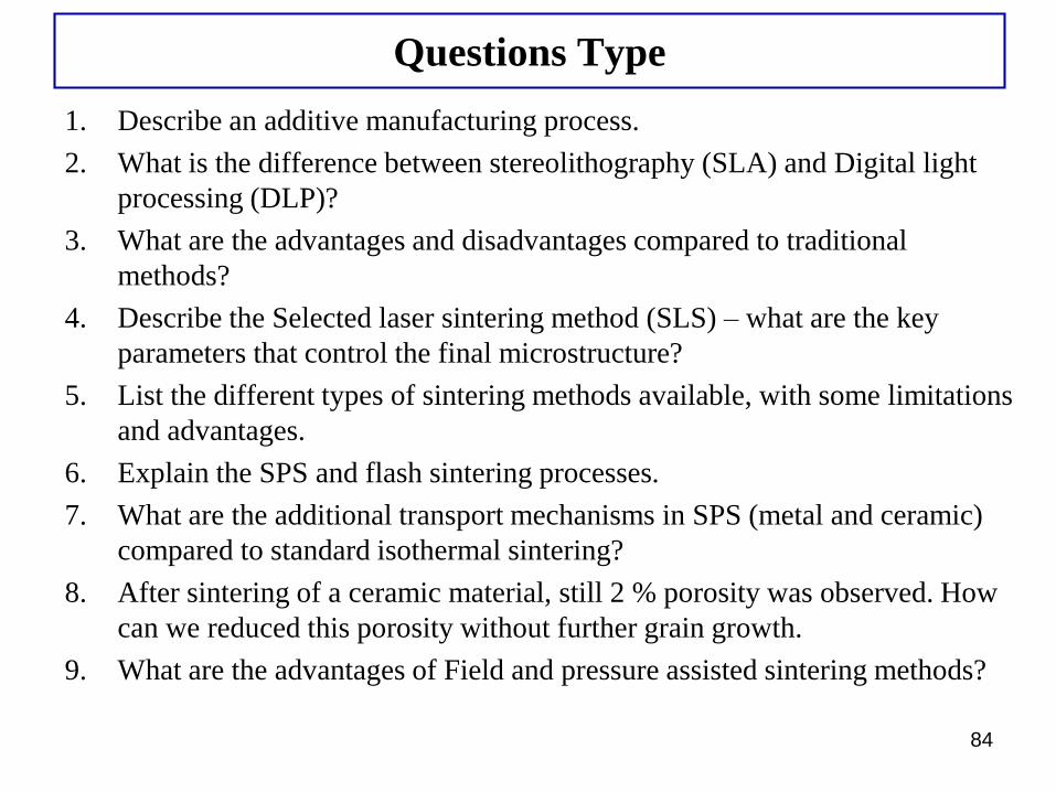
Questions Type
1. Describe an additive manufacturing process.
2. What is the difference between stereolithography (SLA) and Digital light
processing (DLP)?
3. What are the advantages and disadvantages compared to traditional
methods?
4. Describe the Selected laser sintering method (SLS) – what are the key
parameters that control the final microstructure?
5. List the different types of sintering methods available, with some limitations
and advantages.
6. Explain the SPS and flash sintering processes.
7. What are the additional transport mechanisms in SPS (metal and ceramic)
compared to standard isothermal sintering?
8. After sintering of a ceramic material, still 2 % porosity was observed. How
can we reduced this porosity without further grain growth.
9. What are the advantages of Field and pressure assisted sintering methods?