
Potsdam Propeller Test Case (PPTC) Cavitation Tests · PDF filePotsdam Propeller Test Case...
68
Potsdam Propeller Test Case (PPTC) Cavitation Tests with the Model Propeller VP1304 Report 3753 Potsdam, April 2011 Schiffbau-Versuchsanstalt Potsdam GmbH, Marquardter Chaussee 100, 14469 Potsdam Tel. +49 331 56712-0, Fax +49 331 56712-49, www.sva-potsdam.de
Transcript of Potsdam Propeller Test Case (PPTC) Cavitation Tests · PDF filePotsdam Propeller Test Case...

Potsdam Propeller Test Case (PPTC)
Cavitation Tests
with the Model Propeller VP1304
Report 3753
Potsdam, April 2011
Schiffbau-Versuchsanstalt Potsdam GmbH, Marquardter Chaussee 100, 14469 Potsdam
Tel. +49 331 56712-0, Fax +49 331 56712-49, www.sva-potsdam.de

Report 3753
Page 1.1
Potsdam Propeller Test Case (PPTC)
Cavitation Tests
with the Model Propeller VP1304
Client Schiffbau-Versuchsanstalt Potsdam GmbH
Marquardter Chaussee 100
14469 Potsdam
Tel. +49 331 56712-0
Fax +49 331 56712-49
Contractor Schiffbau-Versuchsanstalt Potsdam GmbH
Marquardter Chaussee 100
14469 Potsdam
Tel. +49 331 56712-0
Fax +49 331 56712-49
Author Dipl.-Ing. H.-J. Heinke
This report includes 8 pages text
15 pages tables
20 pages diagrams/drawings
14 pages photographs
9 pages annex
Potsdam, 15/04/2011
Management Author
Report 3753
Page 1.2
Content
Text Page
1 Summary ...................................................................................................................... 1.4
2 Introduction .................................................................................................................. 1.4
3 Tasks ............................................................................................................................ 1.4
4 Description of the model propeller VP1304 ................................................................ 1.5
5 Test arrangement ......................................................................................................... 1.5
6 Test procedure ............................................................................................................. 1.6
7 Test results ................................................................................................................... 1.7
7.1 Open water characteristics ........................................................................................... 1.7
7.2 Cavitation behaviour .................................................................................................... 1.7
8 References .................................................................................................................... 1.8
Tables
Details of model tests .............................................................................................................. 2.1
Extend of model tests with the VP1304 .................................................................................. 2.2
Open water test in the cavitation tunnel, n = 15 s-1
................................................................. 2.3
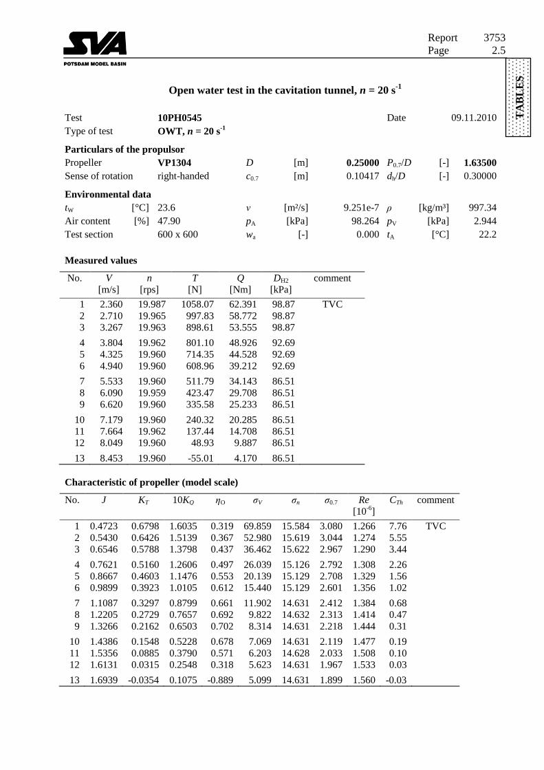
Open water test in the cavitation tunnel, n = 20 s-1
................................................................. 2.5
Open water test in the cavitation tunnel, n = 25 s-1
................................................................. 2.7
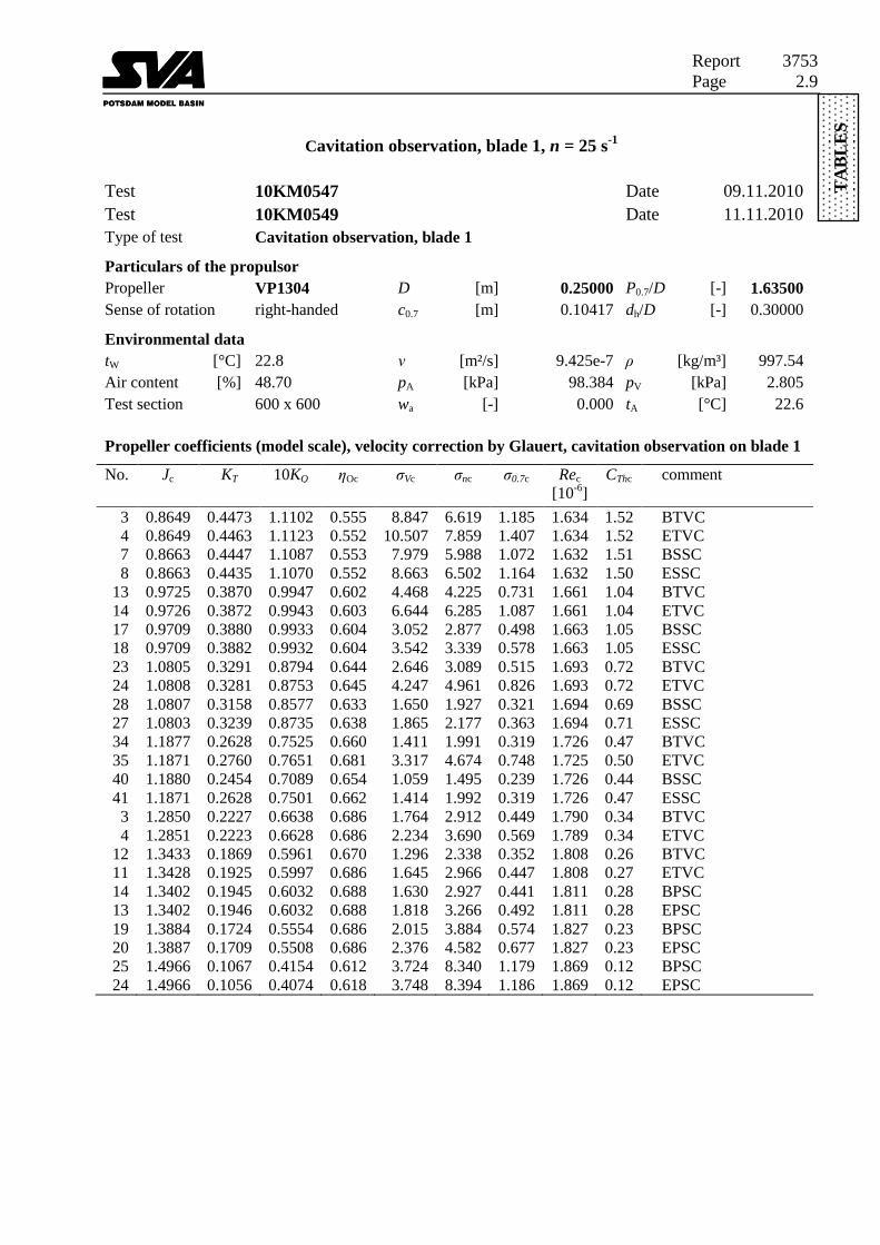
Cavitation observation, blade 1, n = 25 s-1
.............................................................................. 2.9
Cavitation observation, blade 3, n = 25 s-1
............................................................................ 2.10
Cavitation observation, begin of thrust break down, n = 25 s-1
............................................. 2.12
Cavitation observation, Jc = 0.9947 ....................................................................................... 2.13
Cavitation observation, Jc = 1.2535 ....................................................................................... 2.14
Cavitation observation, Jc = 1.4000 ....................................................................................... 2.15
Diagrams and sketches
Model propeller VP1304 ......................................................................................................... 3.1
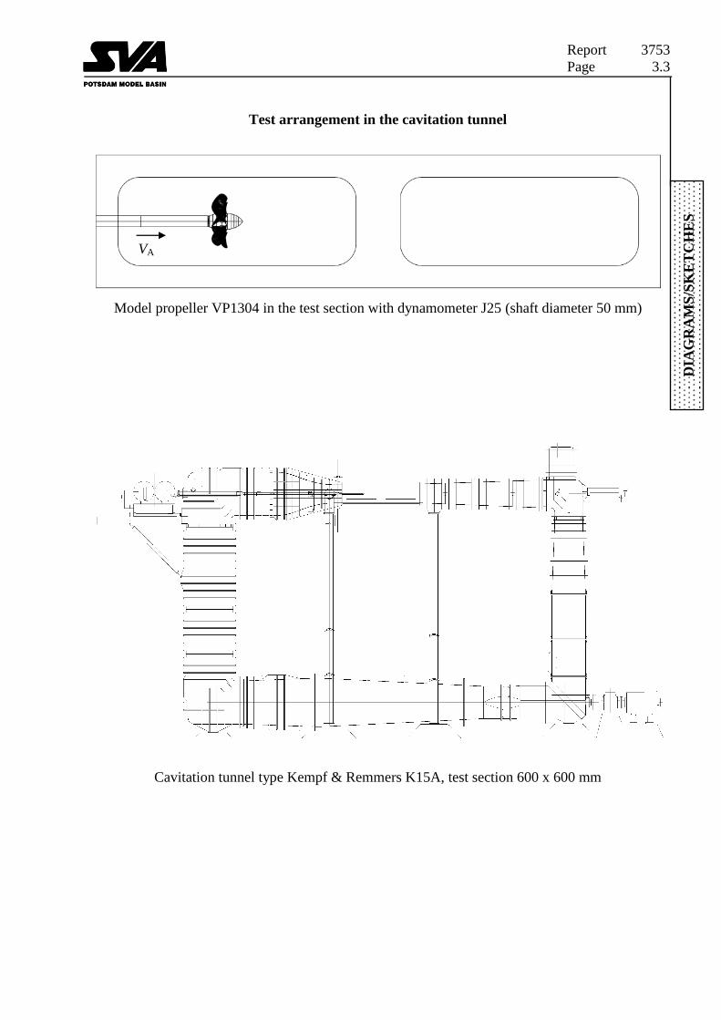
Test arrangement in the cavitation tunnel................................................................................ 3.3
Open water characteristics, measured in the cavitation tunnel ................................................ 3.4
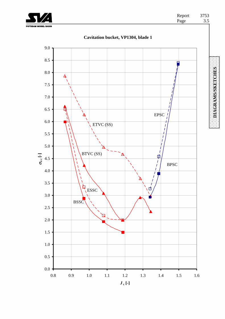
Cavitation bucket, VP1304, blade 1 ........................................................................................ 3.5
Cavitation bucket, VP1304, blade 3 ........................................................................................ 3.6
Begin of tip vortex cavitation, VP1304, blades 1 and 3 .......................................................... 3.7
End of tip vortex cavitation, VP1304, blades 1 and 3 ............................................................. 3.8
Begin of suction side cavitation, VP1304, blades 1 and 3 ...................................................... 3.9
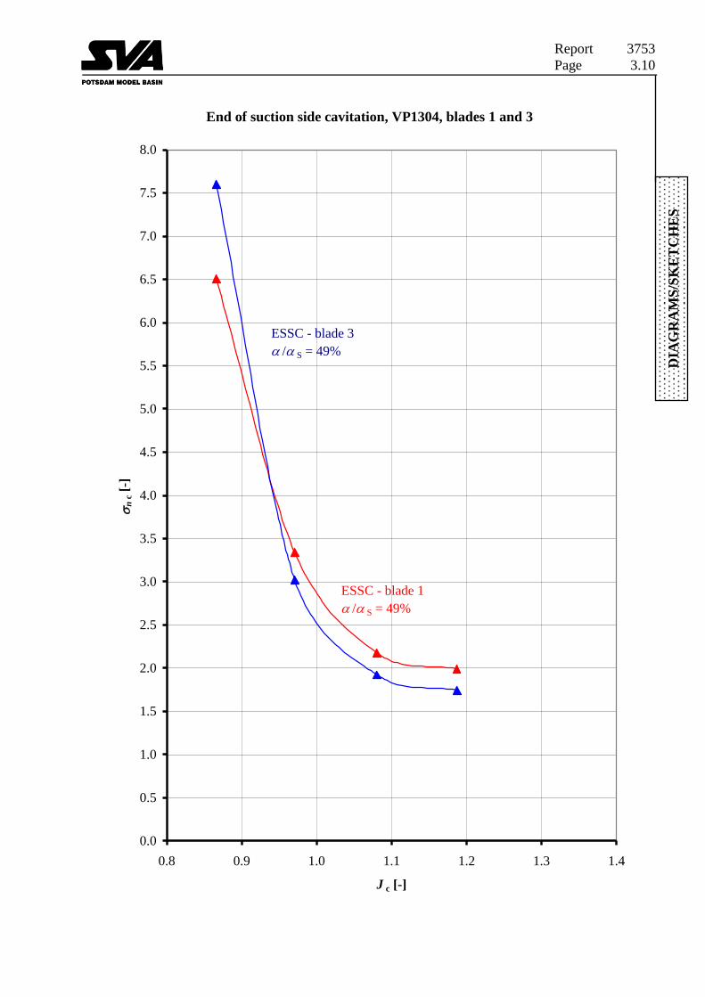
End of suction side cavitation, VP1304, blades 1 and 3........................................................ 3.10
Begin of pressure side cavitation, VP1304, blades 1 and 3 ................................................... 3.11
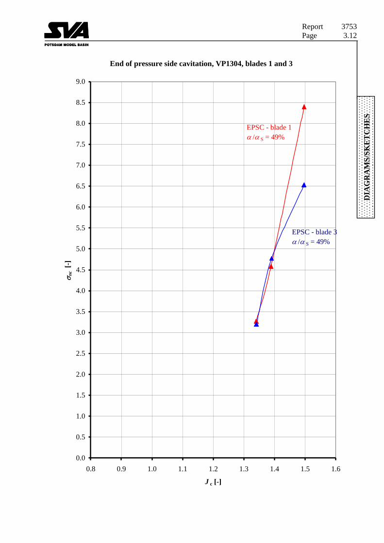
End of pressure side cavitation, VP1304, blades 1 and 3 ...................................................... 3.12
Working points for the cavitation observations ..................................................................... 3.13
Cavitation sketches, suction side, blade 1 ............................................................................. 3.14
Cavitation sketches, pressure side, blade 1............................................................................ 3.16
Cavitation sketches, suction side, blade 3 ............................................................................. 3.17
Cavitation sketches, pressure side, blade 3............................................................................ 3.19
Cavitation sketches, begin of thrust deduction, blade 3 ........................................................ 3.20

Report 3753
Page 1.3
Photographs
Test arrangement in the cavitation tunnel................................................................................ 4.1
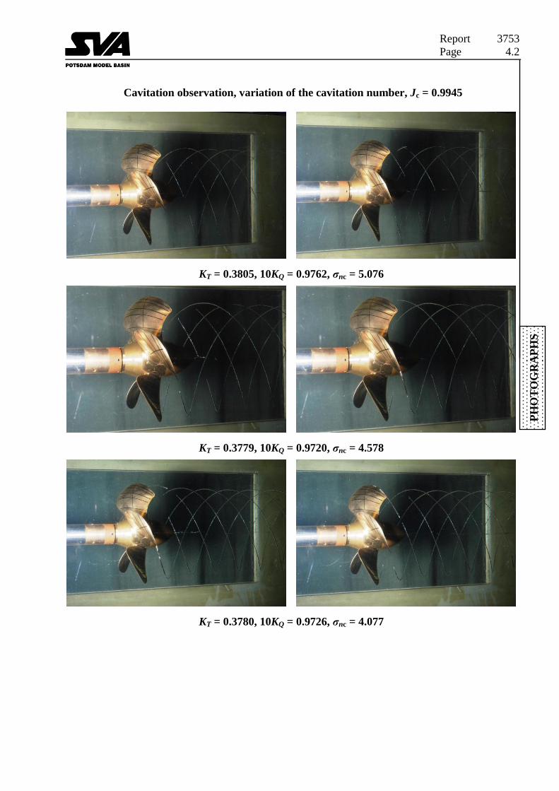
Cavitation observation, variation of the cavitation number, Jc = 0.9945 ................................ 4.2
Cavitation observation, variation of the cavitation number, Jc = 1.2535 ................................ 4.5
Cavitation observation, variation of the cavitation number, Jc = 1.4000 .............................. 4.12
Appendix
Symbols ................................................................................................................................ A1.1
Methods and formulas .......................................................................................................... A2.1
Coordinate system ................................................................................................................ A3.1

Report 3753
Page 1.4
1 Summary
For the SMP’11 workshop the SVA provided the controllable pitch propeller VP1304 as a test
case. Several investigations were conducted with this propeller: open water tests [5],
cavitation tests and LDV measurements [6].
The open water characteristic and the cavitation behaviour of the model propeller VP1304 had
been investigated in the cavitation tunnel K15A of the Potsdam Model Basin (SVA).
The influence of the number of revolutions (Reynolds number) on the open water
characteristics is small in the tested range.
The cavitation buckets were determined for two blades of the model propeller VP1304. There
are differences in the curves for the inception and the end of the tip vortex cavitation. The
reason is the intermitting character of the tip vortex cavitation.
The development of cavitation was observed at three working conditions. Photos and videos
document the cavitation behaviour in the working points at different cavitation numbers.
2 Introduction
The prediction of the cavitation behaviour of a propeller is important to analyse the propeller
in design and off-design conditions [1]. The propeller VP1304 was designed to generate a tip
vortex. Extensive model tests had been carried out to get data for the validation of potential
and viscous flow propeller analysis programs [2], [3], [4], [5], [6].
The open water and cavitation tests had been repeated in preparation for the workshop of the
SMP’11 in Hamburg. This report presents the open water characteristics and cavitation
behaviour of the model propeller VP1304, measured in the small test section (data on page 2.1)
of the cavitation tunnel K15A.
3 Tasks
The model propeller VP1304 was tested in the cavitation tunnel of the Potsdam Model Basin
in homogeneous flow.
The characteristics of the model propeller VP1304 in the cavitation tunnel were measured at
three different numbers of revolutions.
The cavitation buckets of two propeller blades were determined. The cavitation behaviour of
the blades at the cavitation inception points should be documented as hand sketches.
The cavitation behaviour of the propeller was observed at different thrust coefficients and
cavitation numbers. The cavitation behaviour of the propeller in the working point is shown in
photos and videos.

Report 3753
Page 1.5
4 Description of the model propeller VP1304
The propeller was designed by the SVA in 1998. For the manufacture of the propeller cold-
rolled brass was used as raw material. The blades were manufactured on a CNC-based milling
machine with HSC (high speed cutting) technology.
The propeller main properties are shown in table 1 and in the drawing on page 3.1. Photos of
the propeller are shown on page 4.1.
The propeller is a controllable pitch propeller. This affects the propeller blade design near the
hub and results in a 0.3 mm gap between hub and propeller blade near the leading and trailing
edge of the propeller.
Table 1: Main data of model propeller
VP1304
Diameter D [m] 0.250
Design pitch ratio r/R = 0.7 P0.7C/D [–] 1.635
Area ratio AE/A0 [m] 0.77896
Chord length r/R = 0.7 c0.7 [m] 0.10417
Skew θEXT [°] 18.837
Hub ratio dh/D [–] 0.300
Number of blades Z [–] 5
Sense of rotation [–] right
Type controllable pitch propeller
5 Test arrangement
The tests were carried out in the small test section of the cavitation tunnel K15A from Kempf
& Remmers. The dynamometer J25 from Kempf & Remmers was used for the tests. The
dynamometer was arranged in front of the propeller model (drawings on page 3.2, photos on
page 4.1). The shaft inclination was zero degrees.

Report 3753
Page 1.6
6 Test procedure
Apart from the calibration of the measuring device, runs had been made in order to measure
the idle torque with a dummy hub, having the same shape as the real propeller hub.
The open water tests had been carried out at over pressure to avoid cavitation. The number of
revolutions had been varied between n = 15, 20 and 25 s-1
.
The cavitation bucket had been measured with the number of revolutions n = 25 s-1
. Two
blades had been selected for the cavitation tests.
The cavitation behaviour of the propeller had been observed in three working points, given in
table 2.
Table 2: Cavitation observations
Test case 2.3.1
Advanced coefficient J [-] 1.019
Thrust coefficient (non-cavitating) KT [-] 0.387
Cavitation number σn [-] 2.024
Number of revolutions n [s-1
] 24.987
Test case 2.3.2
Advanced coefficient J [-] 1.269
Thrust coefficient (non-cavitating) KT [-] 0.245
Cavitation number σn [-] 1.424
Number of revolutions n [s-1
] 24.986
Test case 2.3.3
Advanced coefficient J [-] 1.408
Thrust coefficient (non-cavitating) KT [-] 0.167
Cavitation number σn [-] 2.000
Number of revolutions n [s-1
] 25.014
On page 2.2 an overview of all tests and test parameters is given.
Report 3753
Page 1.7
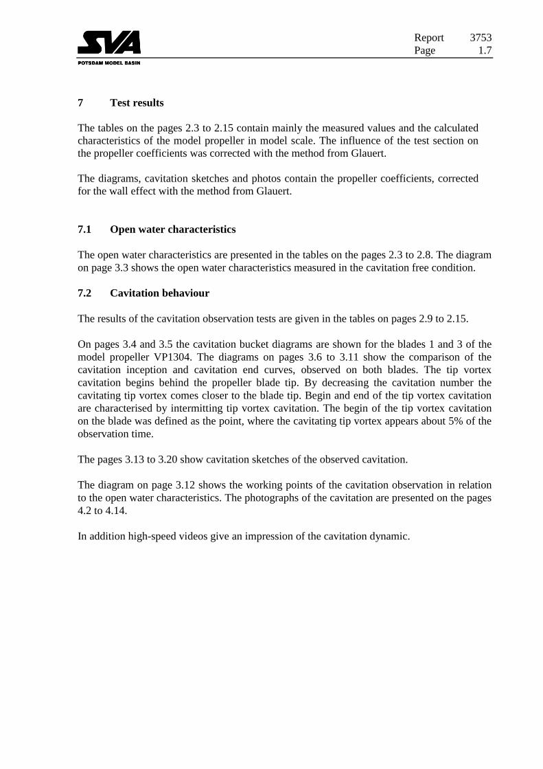
7 Test results
The tables on the pages 2.3 to 2.15 contain mainly the measured values and the calculated
characteristics of the model propeller in model scale. The influence of the test section on
the propeller coefficients was corrected with the method from Glauert.
The diagrams, cavitation sketches and photos contain the propeller coefficients, corrected
for the wall effect with the method from Glauert.
7.1 Open water characteristics
The open water characteristics are presented in the tables on the pages 2.3 to 2.8. The diagram
on page 3.3 shows the open water characteristics measured in the cavitation free condition.
7.2 Cavitation behaviour
The results of the cavitation observation tests are given in the tables on pages 2.9 to 2.15.
On pages 3.4 and 3.5 the cavitation bucket diagrams are shown for the blades 1 and 3 of the
model propeller VP1304. The diagrams on pages 3.6 to 3.11 show the comparison of the
cavitation inception and cavitation end curves, observed on both blades. The tip vortex
cavitation begins behind the propeller blade tip. By decreasing the cavitation number the
cavitating tip vortex comes closer to the blade tip. Begin and end of the tip vortex cavitation
are characterised by intermitting tip vortex cavitation. The begin of the tip vortex cavitation
on the blade was defined as the point, where the cavitating tip vortex appears about 5% of the
observation time.
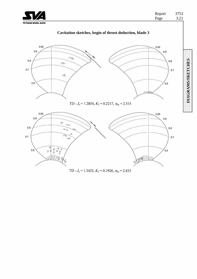
The pages 3.13 to 3.20 show cavitation sketches of the observed cavitation.
The diagram on page 3.12 shows the working points of the cavitation observation in relation
to the open water characteristics. The photographs of the cavitation are presented on the pages
4.2 to 4.14.
In addition high-speed videos give an impression of the cavitation dynamic.

Report 3753
Page 1.8
8 References
[1] Abdel-Maksoud, M.
Numerical and Experimental Study of Cavitation Behaviour of a Propeller STG-Sprechtag Kavitation, 30. Januar 2003, Hamburg
[2] Schmidt, D.
Kennlinien- und Kavitationsgrenzenbestimmungen mit dem Modellpropeller VP1304
Bericht Nr. 2438, Schiffbau-Versuchsanstalt Potsdam, November 1998, (unpublished)
[3] Mach, K.; Hellwig, K.
Experimentelle Bestimmung des Geschwindigkeitsfeldes um den Propeller VP1304
Bericht Nr. 2450, Schiffbau-Versuchsanstalt Potsdam, Januar 1999 (unpublished)
[4] Schmidt, D.; Mach, K.-P.; Hellwig, K.; Heinke, H.-J.
Freifahrt- und Kavitationsversuche sowie Geschwindigkeitsmessungen mit dem
Modellpropeller VP1304
Bericht Nr. 2920, Schiffbau-Versuchsanstalt Potsdam GmbH, Dezember 2002
(unpublished)
[5] Barkmann, U.
Potsdam Propeller Test Case (PPTC) - Open Water Tests with the Model Propeller
VP1304
Report 3752, Schiffbau-Versuchsanstalt Potsdam, April 2011
[6] Mach, K.-P.
Potsdam Propeller Test Case (PPTC) - LDV Velocity Measurements with the Model
Propeller VP1304
Report 3754, Schiffbau-Versuchsanstalt Potsdam, April 2011

Report 3753
Page 2.1
TA
BL
ES
Details of model tests
VP1304
Cavitation tunnel K15A (Kempf & Remmers)
Dimensions of the small test section 0.600 m · 0.600 m with rounded edges
Propeller VP1304
Material of the propeller brass
Type of propeller controllable pitch propeller
Diameter of propeller 0.250 m
Measuring equipment in cavitation tunnel for:
Number of revolutions, thrust and torque Dynamometer J25 with:
Tmax = 3000 N
Qmax = 150 Nm
Inflow velocity manometer (principle of venturi nozzle)
Maximum inflow velocity Vmax = 14 m/s
Report 3753
Page 2.2
TA
BL
ES
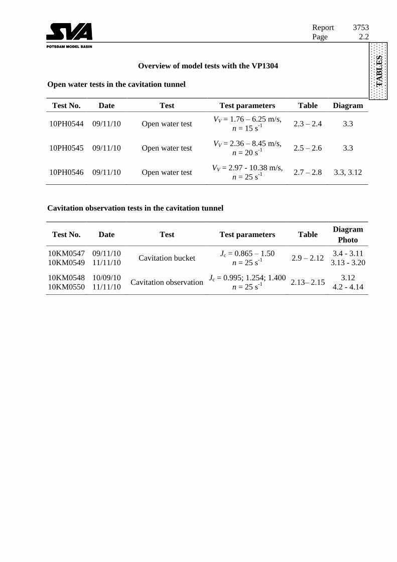
Overview of model tests with the VP1304
Open water tests in the cavitation tunnel
Test No. Date Test Test parameters Table Diagram
10PH0544 09/11/10 Open water test VV = 1.76 – 6.25 m/s,
n = 15 s-1
2.3 – 2.4 3.3
10PH0545 09/11/10 Open water test VV = 2.36 – 8.45 m/s,
n = 20 s-1
2.5 – 2.6 3.3
10PH0546 09/11/10 Open water test VV = 2.97 - 10.38 m/s,
n = 25 s-1
2.7 – 2.8 3.3, 3.12
Cavitation observation tests in the cavitation tunnel
Test No. Date Test Test parameters Table Diagram
Photo
10KM0547
10KM0549
09/11/10
11/11/10 Cavitation bucket
Jc = 0.865 – 1.50
n = 25 s-1
2.9 – 2.12
3.4 - 3.11
3.13 - 3.20
10KM0548
10KM0550
10/09/10
11/11/10 Cavitation observation
Jc = 0.995; 1.254; 1.400
n = 25 s-1
2.13– 2.15
3.12
4.2 - 4.14

Report 3753
Page 2.3
TA
BL
ES
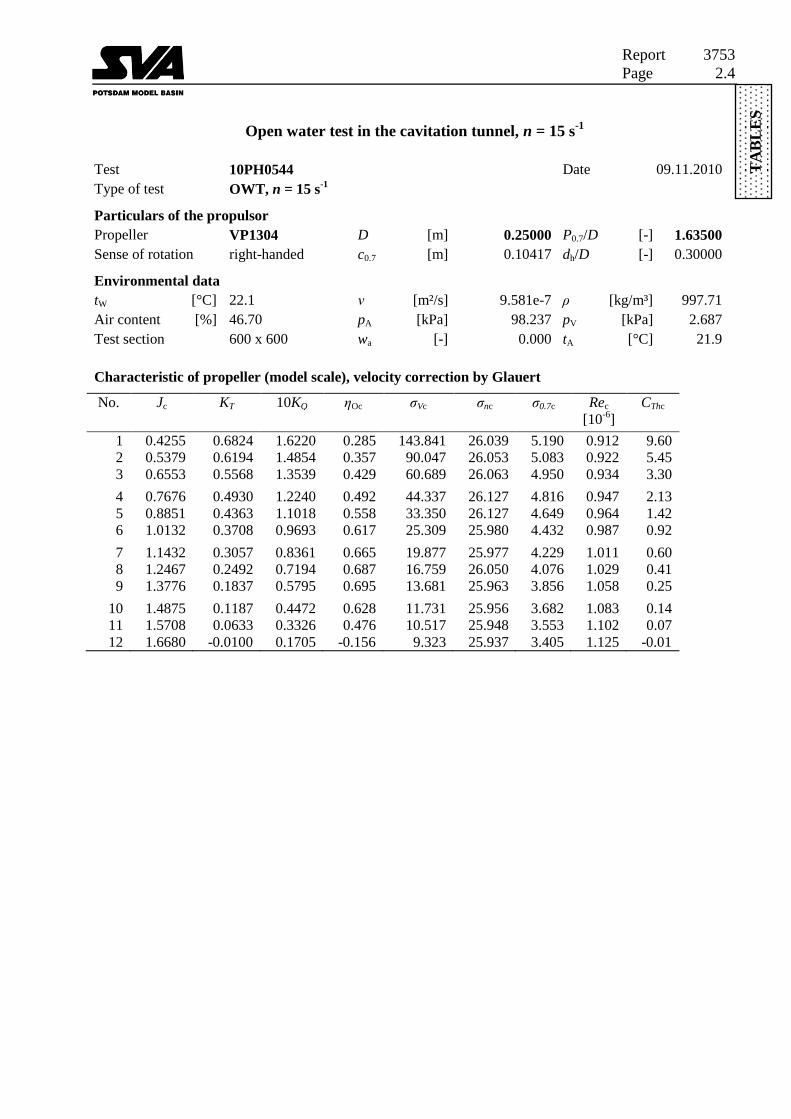
Open water test in the cavitation tunnel, n = 15 s-1
Test 10PH0544 Date 09.11.2010
Type of test OWT, n = 15 s-1
Particulars of the propulsor
Propeller VP1304 D [m] 0.25000 P0.7/D [-] 1.63500
Sense of rotation right-handed c0.7 [m] 0.10417 dh/D [-] 0.30000
Environmental data
tW [°C] 22.1 ν [m²/s] 9.581e-7 ρ [kg/m³] 997.71
Air content [%] 46.70 pA [kPa] 98.237 pV [kPa] 2.687
Test section 600 x 600 wa [-] 0.000 tA [°C] 21.9
Measured values
No. V n T Q DH2
[m/s] [rps] [N] [Nm] [kPa]
1 1.762 14.980 596.83 35.465 86.51
2 2.170 14.978 541.50 32.467 86.51
3 2.594 14.976 486.69 29.586 86.51
4 2.995 14.958 429.92 26.683 86.51
5 3.418 14.958 380.50 24.019 86.51
6 3.890 15.000 325.14 21.249 86.51
7 4.359 14.999 268.02 18.326 86.51
8 4.725 14.976 217.82 15.722 86.51
9 5.207 14.999 161.11 12.701 86.51
10 5.603 14.998 104.03 9.801 86.51
11 5.903 14.998 55.48 7.290 86.51
12 6.254 14.998 -8.79 3.737 86.51
Characteristic of propeller (model scale)
No. J KT 10KQ ηO σV σn σ0.7 Re CTh
[10-6
]
1 0.4705 0.6824 1.6220 0.315 117.424 25.998 5.141 0.916 7.85
2 0.5794 0.6194 1.4854 0.385 77.463 26.006 5.028 0.926 4.70
3 0.6928 0.5568 1.3539 0.453 54.196 26.012 4.893 0.939 2.95
4 0.8009 0.4930 1.2240 0.513 40.647 26.075 4.760 0.952 1.96
5 0.9140 0.4363 1.1018 0.576 31.214 26.075 4.598 0.969 1.33
6 1.0374 0.3708 0.9693 0.632 24.097 25.931 4.386 0.992 0.88
7 1.1625 0.3057 0.8361 0.676 19.190 25.932 4.191 1.014 0.58
8 1.2621 0.2492 0.7194 0.696 16.330 26.012 4.046 1.032 0.40
9 1.3885 0.1837 0.5795 0.701 13.450 25.933 3.834 1.061 0.24
10 1.4944 0.1187 0.4472 0.631 11.613 25.936 3.669 1.084 0.14
11 1.5744 0.0633 0.3326 0.477 10.464 25.936 3.546 1.103 0.07
12 1.6680 -0.0100 0.1705 -0.156 9.323 25.937 3.405 1.125 -0.01
Report 3753
Page 2.4
TA
BL
ES
Open water test in the cavitation tunnel, n = 15 s-1
Test 10PH0544 Date 09.11.2010
Type of test OWT, n = 15 s-1
Particulars of the propulsor
Propeller VP1304 D [m] 0.25000 P0.7/D [-] 1.63500
Sense of rotation right-handed c0.7 [m] 0.10417 dh/D [-] 0.30000
Environmental data
tW [°C] 22.1 ν [m²/s] 9.581e-7 ρ [kg/m³] 997.71
Air content [%] 46.70 pA [kPa] 98.237 pV [kPa] 2.687
Test section 600 x 600 wa [-] 0.000 tA [°C] 21.9
Characteristic of propeller (model scale), velocity correction by Glauert
No. Jc KT 10KQ ηOc σVc σnc σ0.7c Rec CThc
[10-6
]
1 0.4255 0.6824 1.6220 0.285 143.841 26.039 5.190 0.912 9.60
2 0.5379 0.6194 1.4854 0.357 90.047 26.053 5.083 0.922 5.45
3 0.6553 0.5568 1.3539 0.429 60.689 26.063 4.950 0.934 3.30
4 0.7676 0.4930 1.2240 0.492 44.337 26.127 4.816 0.947 2.13
5 0.8851 0.4363 1.1018 0.558 33.350 26.127 4.649 0.964 1.42
6 1.0132 0.3708 0.9693 0.617 25.309 25.980 4.432 0.987 0.92
7 1.1432 0.3057 0.8361 0.665 19.877 25.977 4.229 1.011 0.60
8 1.2467 0.2492 0.7194 0.687 16.759 26.050 4.076 1.029 0.41
9 1.3776 0.1837 0.5795 0.695 13.681 25.963 3.856 1.058 0.25
10 1.4875 0.1187 0.4472 0.628 11.731 25.956 3.682 1.083 0.14
11 1.5708 0.0633 0.3326 0.476 10.517 25.948 3.553 1.102 0.07
12 1.6680 -0.0100 0.1705 -0.156 9.323 25.937 3.405 1.125 -0.01
Report 3753
Page 2.5
TA
BL
ES
Open water test in the cavitation tunnel, n = 20 s-1
Test 10PH0545 Date 09.11.2010
Type of test OWT, n = 20 s-1
Particulars of the propulsor
Propeller VP1304 D [m] 0.25000 P0.7/D [-] 1.63500
Sense of rotation right-handed c0.7 [m] 0.10417 dh/D [-] 0.30000
Environmental data
tW [°C] 23.6 ν [m²/s] 9.251e-7 ρ [kg/m³] 997.34
Air content [%] 47.90 pA [kPa] 98.264 pV [kPa] 2.944
Test section 600 x 600 wa [-] 0.000 tA [°C] 22.2
Measured values
No. V n T Q DH2 comment
[m/s] [rps] [N] [Nm] [kPa]
1 2.360 19.987 1058.07 62.391 98.87 TVC
2 2.710 19.965 997.83 58.772 98.87
3 3.267 19.963 898.61 53.555 98.87
4 3.804 19.962 801.10 48.926 92.69
5 4.325 19.960 714.35 44.528 92.69
6 4.940 19.960 608.96 39.212 92.69
7 5.533 19.960 511.79 34.143 86.51
8 6.090 19.959 423.47 29.708 86.51
9 6.620 19.960 335.58 25.233 86.51
10 7.179 19.960 240.32 20.285 86.51
11 7.664 19.962 137.44 14.708 86.51
12 8.049 19.960 48.93 9.887 86.51
13 8.453 19.960 -55.01 4.170 86.51
Characteristic of propeller (model scale)
No. J KT 10KQ ηO σV σn σ0.7 Re CTh comment
[10-6
]
1 0.4723 0.6798 1.6035 0.319 69.859 15.584 3.080 1.266 7.76 TVC
2 0.5430 0.6426 1.5139 0.367 52.980 15.619 3.044 1.274 5.55
3 0.6546 0.5788 1.3798 0.437 36.462 15.622 2.967 1.290 3.44
4 0.7621 0.5160 1.2606 0.497 26.039 15.126 2.792 1.308 2.26
5 0.8667 0.4603 1.1476 0.553 20.139 15.129 2.708 1.329 1.56
6 0.9899 0.3923 1.0105 0.612 15.440 15.129 2.601 1.356 1.02
7 1.1087 0.3297 0.8799 0.661 11.902 14.631 2.412 1.384 0.68
8 1.2205 0.2729 0.7657 0.692 9.822 14.632 2.313 1.414 0.47
9 1.3266 0.2162 0.6503 0.702 8.314 14.631 2.218 1.444 0.31
10 1.4386 0.1548 0.5228 0.678 7.069 14.631 2.119 1.477 0.19
11 1.5356 0.0885 0.3790 0.571 6.203 14.628 2.033 1.508 0.10
12 1.6131 0.0315 0.2548 0.318 5.623 14.631 1.967 1.533 0.03
13 1.6939 -0.0354 0.1075 -0.889 5.099 14.631 1.899 1.560 -0.03

Report 3753
Page 2.6
TA
BL
ES
Open water test in the cavitation tunnel, n = 20 s-1
Test 10PH0545 Date 09.11.2010
Type of test OWT, n = 20 s-1
Particulars of the propulsor
Propeller VP1304 D [m] 0.25000 P0.7/D [-] 1.63500
Sense of rotation right-handed c0.7 [m] 0.10417 dh/D [-] 0.30000
Environmental data
tW [°C] 23.6 ν [m²/s] 9.251e-7 ρ [kg/m³] 997.34
Air content [%] 47.90 pA [kPa] 98.264 pV [kPa] 2.944
Test section 600 x 600 wa [-] 0.000 tA [°C] 22.2
Characteristic of propeller (model scale), velocity correction by Glauert
No. Jc KT 10KQ ηOc σVc σnc σ0.7c Rec CThc comment
[10-6
]
1 0.4274 0.6798 1.6035 0.288 85.542 15.624 3.113 1.261 9.48 TVC
2 0.4999 0.6426 1.5139 0.338 62.670 15.664 3.080 1.268 6.55
3 0.6155 0.5788 1.3798 0.411 41.365 15.672 3.005 1.284 3.89
4 0.7273 0.5160 1.2606 0.474 28.694 15.178 2.829 1.302 2.48
5 0.8361 0.4603 1.1476 0.534 21.718 15.181 2.743 1.322 1.68
6 0.9641 0.3923 1.0105 0.596 16.330 15.179 2.633 1.350 1.07
7 1.0876 0.3297 0.8799 0.649 12.409 14.677 2.439 1.379 0.71
8 1.2035 0.2729 0.7657 0.683 10.131 14.673 2.335 1.409 0.48
9 1.3135 0.2162 0.6503 0.695 8.500 14.665 2.235 1.440 0.32
10 1.4295 0.1548 0.5228 0.674 7.173 14.657 2.131 1.474 0.19
11 1.5305 0.0885 0.3790 0.569 6.251 14.643 2.040 1.506 0.10
12 1.6112 0.0315 0.2548 0.317 5.638 14.637 1.969 1.532 0.03
13 1.6939 -0.0354 0.1075 -0.889 5.099 14.631 1.899 1.560 -0.03

Report 3753
Page 2.7
TA
BL
ES
Open water test in the cavitation tunnel, n = 25 s-1
Test 10PH0546 Date 09.11.2010
Type of test OWT, n = 25 s-1
Particulars of the propulsor
Propeller VP1304 D [m] 0.25000 P0.7/D [-] 1.63500
Sense of rotation right-handed c0.7 [m] 0.10417 dh/D [-] 0.30000
Environmental data
tW [°C] 22.6 ν [m²/s] 9.470e-7 ρ [kg/m³] 997.59
Air content [%] 48.20 pA [kPa] 98.285 pV [kPa] 2.771
Test section 600 x 600 wa [-] 0.000 tA [°C] 22.3
Measured values
No. V n T Q DH2 comment
[m/s] [rps] [N] [Nm] [kPa]
1 2.970 25.005 1668.74 98.123 98.87 SSC
2 3.583 24.977 1530.72 90.655 98.87 SSC
3 4.250 24.976 1382.11 82.767 98.87 SSC
4 4.917 24.977 1226.86 74.618 96.40
5 5.533 24.975 1096.89 68.183 93.93
6 6.262 24.974 940.52 60.396 86.51
7 6.924 24.974 801.93 53.486 86.51
8 7.614 24.974 660.89 46.229 82.81
9 8.253 24.973 525.44 39.313 77.86
10 8.883 24.973 390.52 32.116 74.15
11 9.457 24.973 244.35 24.348 70.45
12 9.935 24.972 102.45 16.716 69.21 PSC
13 10.377 24.972 -39.66 9.139 67.97 PSC
Characteristic of propeller (model scale)
No. J KT 10KQ ηO σV σn σ0.7 Re CTh comment
[10-6
]
1 0.4752 0.6849 1.6109 0.322 44.133 9.964 1.969 1.548 7.72 SSC
2 0.5739 0.6297 1.4917 0.386 30.326 9.987 1.933 1.562 4.87 SSC
3 0.6807 0.5686 1.3620 0.452 21.555 9.988 1.885 1.582 3.12 SSC
4 0.7875 0.5047 1.2278 0.515 15.901 9.860 1.807 1.605 2.07
5 0.8861 0.4513 1.1220 0.567 12.397 9.734 1.732 1.629 1.46
6 1.0029 0.3870 0.9940 0.621 9.298 9.353 1.601 1.661 0.98
7 1.1089 0.3299 0.8803 0.662 7.606 9.353 1.542 1.692 0.68
8 1.2194 0.2719 0.7608 0.694 6.162 9.163 1.449 1.728 0.47
9 1.3220 0.2162 0.6471 0.703 5.098 8.909 1.353 1.763 0.32
10 1.4229 0.1607 0.5286 0.688 4.306 8.718 1.271 1.799 0.20
11 1.5148 0.1005 0.4007 0.605 3.716 8.527 1.196 1.834 0.11
12 1.5914 0.0422 0.2752 0.388 3.342 8.465 1.149 1.865 0.04 PSC
13 1.6621 -0.0163 0.1504 -0.287 3.041 8.400 1.106 1.894 -0.02 PSC

Report 3753
Page 2.8
TA
BL
ES
Open water test in the cavitation tunnel, n = 25 s-1
Test 10PH0546 Date 09.11.2010
Type of test OWT, n = 25 s-1
Particulars of the propulsor
Propeller VP1304 D [m] 0.25000 P0.7/D [-] 1.63500
Sense of rotation right-handed c0.7 [m] 0.10417 dh/D [-] 0.30000
Environmental data
tW [°C] 22.6 ν [m²/s] 9.470e-7 ρ [kg/m³] 997.59
Air content [%] 48.20 pA [kPa] 98.285 pV [kPa] 2.771
Test section 600 x 600 wa [-] 0.000 tA [°C] 22.3
Characteristic of propeller (model scale), velocity correction by Glauert
No. Jc KT 10KQ ηOc σVc σnc σ0.7c Rec CThc comment
[10-6
]
1 0.4300 0.6849 1.6109 0.291 54.122 10.005 1.993 1.541 9.43 SSC
2 0.5320 0.6297 1.4917 0.357 35.456 10.033 1.960 1.555 5.67 SSC
3 0.6425 0.5686 1.3620 0.427 24.316 10.038 1.912 1.574 3.51 SSC
4 0.7534 0.5047 1.2278 0.493 17.461 9.912 1.834 1.597 2.26
5 0.8560 0.4513 1.1220 0.548 13.355 9.786 1.757 1.621 1.57
6 0.9777 0.3870 0.9940 0.606 9.837 9.403 1.624 1.653 1.03
7 1.0877 0.3299 0.8803 0.649 7.944 9.400 1.562 1.686 0.71
8 1.2026 0.2719 0.7608 0.684 6.363 9.203 1.465 1.722 0.48
9 1.3090 0.2162 0.6471 0.696 5.219 8.943 1.365 1.758 0.32
10 1.4134 0.1607 0.5286 0.684 4.378 8.745 1.280 1.796 0.20
11 1.5090 0.1005 0.4007 0.603 3.752 8.545 1.201 1.832 0.11
12 1.5891 0.0422 0.2752 0.388 3.355 8.472 1.151 1.864 0.04 PSC
13 1.6621 -0.0163 0.1504 -0.287 3.041 8.400 1.106 1.894 -0.02 PSC
Report 3753
Page 2.9
TA
BL
ES
Cavitation observation, blade 1, n = 25 s-1
Test 10KM0547 Date 09.11.2010
Test 10KM0549 Date 11.11.2010
Type of test Cavitation observation, blade 1
Particulars of the propulsor
Propeller VP1304 D [m] 0.25000 P0.7/D [-] 1.63500
Sense of rotation right-handed c0.7 [m] 0.10417 dh/D [-] 0.30000
Environmental data
tW [°C] 22.8 ν [m²/s] 9.425e-7 ρ [kg/m³] 997.54
Air content [%] 48.70 pA [kPa] 98.384 pV [kPa] 2.805
Test section 600 x 600 wa [-] 0.000 tA [°C] 22.6
Propeller coefficients (model scale), velocity correction by Glauert, cavitation observation on blade 1
No. Jc KT 10KQ ηOc σVc σnc σ0.7c Rec CThc comment
[10-6
]
3 0.8649 0.4473 1.1102 0.555 8.847 6.619 1.185 1.634 1.52 BTVC
4 0.8649 0.4463 1.1123 0.552 10.507 7.859 1.407 1.634 1.52 ETVC
7 0.8663 0.4447 1.1087 0.553 7.979 5.988 1.072 1.632 1.51 BSSC
8 0.8663 0.4435 1.1070 0.552 8.663 6.502 1.164 1.632 1.50 ESSC
13 0.9725 0.3870 0.9947 0.602 4.468 4.225 0.731 1.661 1.04 BTVC
14 0.9726 0.3872 0.9943 0.603 6.644 6.285 1.087 1.661 1.04 ETVC
17 0.9709 0.3880 0.9933 0.604 3.052 2.877 0.498 1.663 1.05 BSSC
18 0.9709 0.3882 0.9932 0.604 3.542 3.339 0.578 1.663 1.05 ESSC
23 1.0805 0.3291 0.8794 0.644 2.646 3.089 0.515 1.693 0.72 BTVC
24 1.0808 0.3281 0.8753 0.645 4.247 4.961 0.826 1.693 0.72 ETVC
28 1.0807 0.3158 0.8577 0.633 1.650 1.927 0.321 1.694 0.69 BSSC
27 1.0803 0.3239 0.8735 0.638 1.865 2.177 0.363 1.694 0.71 ESSC
34 1.1877 0.2628 0.7525 0.660 1.411 1.991 0.319 1.726 0.47 BTVC
35 1.1871 0.2760 0.7651 0.681 3.317 4.674 0.748 1.725 0.50 ETVC
40 1.1880 0.2454 0.7089 0.654 1.059 1.495 0.239 1.726 0.44 BSSC
41 1.1871 0.2628 0.7501 0.662 1.414 1.992 0.319 1.726 0.47 ESSC
3 1.2850 0.2227 0.6638 0.686 1.764 2.912 0.449 1.790 0.34 BTVC
4 1.2851 0.2223 0.6628 0.686 2.234 3.690 0.569 1.789 0.34 ETVC
12 1.3433 0.1869 0.5961 0.670 1.296 2.338 0.352 1.808 0.26 BTVC
11 1.3428 0.1925 0.5997 0.686 1.645 2.966 0.447 1.808 0.27 ETVC
14 1.3402 0.1945 0.6032 0.688 1.630 2.927 0.441 1.811 0.28 BPSC
13 1.3402 0.1946 0.6032 0.688 1.818 3.266 0.492 1.811 0.28 EPSC
19 1.3884 0.1724 0.5554 0.686 2.015 3.884 0.574 1.827 0.23 BPSC
20 1.3887 0.1709 0.5508 0.686 2.376 4.582 0.677 1.827 0.23 EPSC
25 1.4966 0.1067 0.4154 0.612 3.724 8.340 1.179 1.869 0.12 BPSC
24 1.4966 0.1056 0.4074 0.618 3.748 8.394 1.186 1.869 0.12 EPSC

Report 3753
Page 2.10
TA
BL
ES
Cavitation observation, blade 3, n = 25 s-1
Test 10KM0547 Date 09.11.2010
Test 10KM0549 Date 11.11.2010
Type of test Cavitation observation, blade 3
Particulars of the propulsor
Propeller VP1304 D [m] 0.25000 P0.7/D [-] 1.63500
Sense of rotation right-handed c0.7 [m] 0.10417 dh/D [-] 0.30000
Environmental data
tW [°C] 22.8 ν [m²/s] 9.425e-7 ρ [kg/m³] 997.54
Air content [%] 48.70 pA [kPa] 98.384 pV [kPa] 2.805
Test section 600 x 600 wa [-] 0.000 tA [°C] 22.6
Propeller coefficients (model scale), velocity correction by Glauert, cavitation observation on blade 3
No. Jc KT 10KQ ηOc σVc σnc σ0.7c Rec CThc comment
[10-6
]
2 0.8662 0.4478 1.1091 0.557 8.825 6.622 1.185 1.632 1.52 BTVC
1 0.8659 0.4456 1.1067 0.555 9.963 7.470 1.337 1.633 1.51 ETVC
5 0.8663 0.4439 1.1036 0.555 8.486 6.369 1.140 1.633 1.51 BSSC
6 0.8663 0.4440 1.1067 0.553 10.130 7.602 1.361 1.633 1.51 ESSC
10 0.8656 0.4504 1.1133 0.557 4.950 3.709 0.664 1.633 1.53 BRC
11 0.9722 0.3877 0.9913 0.605 5.005 4.731 0.818 1.661 1.04 BTVC
12 0.9725 0.3868 0.9929 0.603 6.493 6.141 1.062 1.661 1.04 ETVC
15 0.9709 0.3899 0.9953 0.605 3.098 2.921 0.505 1.663 1.05 BSSC
16 0.9709 0.3877 0.9908 0.605 3.204 3.020 0.523 1.663 1.05 ESSC
19 0.9709 0.3871 0.9918 0.603 3.644 3.436 0.595 1.663 1.05 BRC
21 1.0804 0.3309 0.8793 0.647 2.858 3.337 0.556 1.693 0.72 BTVC
22 1.0805 0.3303 0.8765 0.648 3.992 4.661 0.776 1.693 0.72 ETVC
26 1.0807 0.3122 0.8466 0.634 1.487 1.737 0.289 1.694 0.68 BSSC
25 1.0805 0.3181 0.8608 0.636 1.648 1.923 0.320 1.694 0.69 ESSC
29 1.0799 0.3318 0.8770 0.650 2.643 3.082 0.514 1.694 0.72 BRC (SS)
30 1.0802 0.3111 0.8456 0.633 1.440 1.680 0.280 1.695 0.68 FC
31 1.0796 0.3199 0.8678 0.633 1.697 1.978 0.330 1.695 0.70 BRC (PS)
32 1.1867 0.2736 0.7721 0.669 1.659 2.336 0.374 1.726 0.49 BTVC
33 1.1869 0.2748 0.7644 0.679 2.617 3.686 0.590 1.725 0.50 ETVC
36 1.1866 0.2706 0.7659 0.667 1.518 2.138 0.342 1.726 0.49 FC
37 1.1863 0.2752 0.7681 0.676 1.840 2.589 0.415 1.726 0.50 BRC (SS), BRC (PS)
38 1.1882 0.2387 0.6944 0.650 0.921 1.300 0.208 1.727 0.43 BSSC
39 1.1875 0.2543 0.7288 0.659 1.235 1.742 0.279 1.726 0.46 ESSC

Report 3753
Page 2.11
TA
BL
ES
Cavitation observation, blade 3, n = 25 s-1
Test 10KM0547 Date 09.11.2010
Test 10KM0549 Date 11.11.2010
Type of test Cavitation observation, blade 3
Particulars of the propulsor
Propeller VP1304 D [m] 0.25000 P0.7/D [-] 1.63500
Sense of rotation right-handed c0.7 [m] 0.10417 dh/D [-] 0.30000
Environmental data
tW [°C] 22.8 ν [m²/s] 9.425e-7 ρ [kg/m³] 997.54
Air content [%] 48.70 pA [kPa] 98.384 pV [kPa] 2.805
Test section 600 x 600 wa [-] 0.000 tA [°C] 22.6
Propeller coefficients (model scale), velocity correction by Glauert, cavitation observation on blade 3
No. Jc KT 10KQ ηOc σVc σnc σ0.7c Rec CThc comment
[10-6]
1 1.2852 0.2137 0.6527 0.670 1.309 2.162 0.333 1.790 0.33 BTVC
2 1.2848 0.2241 0.6648 0.689 2.554 4.216 0.650 1.790 0.35 ETVC
5 1.2850 0.2239 0.6644 0.689 2.278 3.762 0.580 1.790 0.35 BRC (PS)
6 1.2854 0.2210 0.6608 0.684 1.599 2.642 0.407 1.789 0.34 BRC (SS)
8 1.3409 0.1966 0.6088 0.689 1.653 2.973 0.448 1.810 0.28 BPSC
7 1.3406 0.1967 0.6096 0.688 1.782 3.202 0.483 1.810 0.28 EPSC
10 1.3433 0.1841 0.5891 0.668 1.225 2.210 0.333 1.808 0.26 BTVC
9 1.3425 0.1926 0.6032 0.682 1.461 2.633 0.397 1.808 0.27 ETVC
15 1.3401 0.1954 0.6053 0.689 2.273 4.081 0.615 1.810 0.28 BRC (PS)
16 1.3401 0.1954 0.6052 0.689 1.731 3.109 0.469 1.810 0.28 BRC (SS)
18 1.3911 0.1705 0.5527 0.683 2.122 4.107 0.606 1.825 0.22 BPSC
17 1.3907 0.1703 0.5506 0.685 2.468 4.774 0.705 1.825 0.22 EPSC
21 1.3885 0.1725 0.5544 0.688 2.810 5.418 0.801 1.827 0.23 BRC (PS)
23 1.4967 0.1034 0.4098 0.601 2.698 6.043 0.854 1.869 0.12 BPSC
22 1.4964 0.1061 0.4157 0.608 2.917 6.532 0.923 1.869 0.12 EPSC

Report 3753
Page 2.12
TA
BL
ES
Cavitation observation, begin of thrust break down, n = 25 s-1
Test 10KM0547 Date 09.11.2010
Test 10KM0549 Date 11.11.2010
Type of test Cavitation observation, begin of thrust break down
Particulars of the propulsor
Propeller VP1304 D [m] 0.25000 P0.7/D [-] 1.63500
Sense of rotation right-handed c0.7 [m] 0.10417 dh/D [-] 0.30000
Environmental data
tW [°C] 22.8 ν [m²/s] 9.425e-7 ρ [kg/m³] 997.54
Air content [%] 48.70 pA [kPa] 98.384 pV [kPa] 2.805
Test section 600 x 600 wa [-] 0.000 tA [°C] 22.6
Propeller coefficients (model scale), velocity correction by Glauert, inception of thrust break down
No. Jc KT 10KQ ηOc σVc σnc σ0.7c Rec CThc comment
[10-6
]
9 0.8662 0.4393 1.1045 0.548 2.534 1.901 0.340 1.633 1.49 TD
20 0.9714 0.3819 0.9904 0.596 2.142 2.021 0.350 1.663 1.03 TD
25 1.0805 0.3181 0.8608 0.636 1.648 1.923 0.320 1.694 0.69 TD
36 1.1866 0.2706 0.7659 0.667 1.518 2.138 0.342 1.726 0.49 TD
6 1.2854 0.2217 0.6608 0.686 1.522 2.515 0.388 1.789 0.34 TD
9 1.3425 0.1926 0.6032 0.682 1.461 2.633 0.397 1.808 0.27 TD

Report 3753
Page 2.13
TA
BL
ES
Cavitation observation, Jc = 0.9947
Test 10KM0548 Date 10.11.2010
Type of test Working points for photos and videos
Particulars of the propulsor
Propeller VP1304 D [m] 0.25000 P0.7/D [-] 1.63500
Sense of rotation right-handed c0.7 [m] 0.10417 dh/D [-] 0.30000
Environmental data
tW [°C] 23.2 ν [m²/s] 9.337e-7 ρ [kg/m³] 997.44
Air content [%] 53.50 pA [kPa] 98.878 pV [kPa] 2.873
Test section 600 x 600 wa [-] 0.000 tA [°C] 23.1
Measured values
No. V n T Q DH2
[m/s] [rps] [N] [Nm] [kPa]
1 6.367 24.996 926.30 59.407 2.09
2 6.367 24.988 919.24 59.117 -7.65
3 6.367 24.987 919.60 59.150 -17.40
4 6.367 24.990 914.46 59.063 -36.88
5 6.367 24.987 908.70 58.980 -56.37
Characteristic of propeller (model scale)
No. J KT 10KQ ηO σV σn σ0.7 Re CTh
[10-6
]
1 1.0189 0.3805 0.9762 0.632 4.841 5.026 0.856 1.690 0.93
2 1.0193 0.3779 0.9720 0.631 4.359 4.529 0.771 1.690 0.93
3 1.0193 0.3780 0.9726 0.631 3.877 4.028 0.686 1.690 0.93
4 1.0192 0.3758 0.9709 0.628 2.913 3.026 0.515 1.690 0.92
5 1.0193 0.3735 0.9698 0.625 1.949 2.024 0.345 1.690 0.92
Characteristic of propeller (model scale), velocity correction by Glauert
No. Jc KT 10KQ ηOc σVc σnc σ0.7c Rec CThc
[10-6
]
1 0.9941 0.3805 0.9762 0.617 5.136 5.076 0.871 1.683 0.98
2 0.9947 0.3779 0.9720 0.615 4.627 4.578 0.786 1.683 0.97
3 0.9947 0.3780 0.9726 0.615 4.121 4.077 0.700 1.683 0.97
4 0.9946 0.3758 0.9709 0.613 3.109 3.075 0.528 1.683 0.97
5 0.9949 0.3735 0.9698 0.610 2.095 2.074 0.356 1.683 0.96

Report 3753
Page 2.14
TA
BL
ES
Cavitation observation, Jc = 1.2535
Test 10KM0548 Date 10.11.2010
Type of test Working points for photos and videos
Particulars of the propulsor
Propeller VP1304 D [m] 0.25000 P0.7/D [-] 1.63500
Sense of rotation right-handed c0.7 [m] 0.10417 dh/D [-] 0.30000
Environmental data
tW [°C] 23.2 ν [m²/s] 9.337e-7 ρ [kg/m³] 997.44
Air content [%] 53.50 pA [kPa] 98.878 pV [kPa] 2.873
Test section 600 x 600 wa [-] 0.000 tA [°C] 23.1
Measured values
No. V n T Q DH2
[m/s] [rps] [N] [Nm] [kPa]
1 7.924 24.996 589.43 42.372 -36.88
2 7.924 24.995 583.53 42.376 -46.63
3 7.924 24.999 574.39 42.233 -52.48
4 7.923 24.993 556.42 41.241 -56.37
5 7.924 24.986 502.08 38.383 -68.06
Characteristic of propeller (model scale)
No. J KT 10KQ ηO σV σn σ0.7 Re CTh
[10-6
]
1 1.2681 0.2421 0.6962 0.702 1.881 3.024 0.469 1.770 0.38
2 1.2681 0.2397 0.6963 0.695 1.569 2.523 0.392 1.770 0.38
3 1.2680 0.2359 0.6938 0.686 1.382 2.222 0.345 1.770 0.37
4 1.2680 0.2286 0.6778 0.681 1.258 2.023 0.314 1.770 0.36
5 1.2686 0.2064 0.6312 0.660 0.885 1.424 0.221 1.770 0.33
Characteristic of propeller (model scale), velocity correction by Glauert
No. Jc KT 10KQ ηOc σVc σnc σ0.7c Rec CThc
[10-6
]
1 1.2531 0.2421 0.6962 0.694 1.950 3.062 0.478 1.765 0.39
2 1.2534 0.2397 0.6963 0.687 1.630 2.560 0.400 1.765 0.39
3 1.2535 0.2359 0.6938 0.678 1.438 2.259 0.353 1.765 0.38
4 1.2537 0.2286 0.6778 0.673 1.310 2.059 0.321 1.765 0.37
5 1.2557 0.2064 0.6312 0.654 0.923 1.456 0.227 1.765 0.33

Report 3753
Page 2.15
TA
BL
ES
Cavitation observation, Jc = 1.4000
Test 10KM0550 Date 11.11.2010
Type of test Working points for photos and videos
Particulars of the propulsor
Propeller VP1304 D [m] 0.25000 P0.7/D [-] 1.63500
Sense of rotation right-handed c0.7 [m] 0.10417 dh/D [-] 0.30000
Environmental data
tW [°C] 23.5 ν [m²/s] 9.272e-7 ρ [kg/m³] 997.37
Air content [%] 58.50 pA [kPa] 100.585 pV [kPa] 2.926
Test section 600 x 600 wa [-] 0.000 tA [°C] 21.9
Measured values
No. V n T Q DH2
[m/s] [rps] [N] [Nm] [kPa]
1 8.807 24.993 399.27 32.667 -19.49
2 8.807 24.997 391.50 32.268 -38.97
3 8.807 25.014 331.94 29.801 -58.46
Characteristic of propeller (model scale)
No. J KT 10KQ ηO σV σn σ0.7 Re CTh
[10-6
]
1 1.4095 0.1641 0.5369 0.685 2.016 4.004 0.587 1.834 0.21
2 1.4092 0.1608 0.5302 0.680 1.512 3.003 0.440 1.834 0.21
3 1.4083 0.1362 0.4890 0.624 1.008 1.999 0.293 1.835 0.17
Characteristic of propeller (model scale), velocity correction by Glauert
No. Jc KT 10KQ ηOc σVc σnc σ0.7c Rec CThc
[10-6
]
1 1.3998 0.1641 0.5369 0.681 2.058 4.032 0.593 1.830 0.21
2 1.3998 0.1608 0.5302 0.676 1.546 3.029 0.446 1.831 0.21
3 1.4001 0.1362 0.4890 0.621 1.031 2.022 0.298 1.832 0.18

Report 3753
Page 3.1
DIA
GR
AM
S/S
KE
TC
HE
S
Model propeller VP1304

Report 3753
Page 3.2
DIA
GR
AM
S/S
KE
TC
HE
S
Propeller VP1304
VP1304 in cavitation tunnel configuration
Report 3753
Page 3.3
DIA
GR
AM
S/S
KE
TC
HE
S
Test arrangement in the cavitation tunnel
Model propeller VP1304 in the test section with dynamometer J25 (shaft diameter 50 mm)
Cavitation tunnel type Kempf & Remmers K15A, test section 600 x 600 mm
VA

Report 3753
Page 3.4
DIA
GR
AM
S/S
KE
TC
HE
S
Open water characteristics, measured in the cavitation tunnel
0.0
0.1
0.2
0.3
0.4
0.5
0.6
0.7
0.8
0.9
1.0
1.1
1.2
1.3
1.4
1.5
1.6
1.7
0.4 0.5 0.6 0.7 0.8 0.9 1.0 1.1 1.2 1.3 1.4 1.5 1.6 1.7
J c [-]
KT
, 10K
Q, h
Oc [
-]
10K Q
h Oc
K T
_______ n = 15 s
-1, Re c = 0.91 - 1.12 10
6
__ __ __ n = 20 s
-1, Re c = 1.26 - 1.56 10
6
_ _ _ _ _ n = 25 s
-1, Re c = 1.54 - 1.89 10
6
Report 3753
Page 3.5
DIA
GR
AM
S/S
KE
TC
HE
S
Cavitation bucket, VP1304, blade 1
0.0
0.5
1.0
1.5
2.0
2.5
3.0
3.5
4.0
4.5
5.0
5.5
6.0
6.5
7.0
7.5
8.0
8.5
9.0
0.8 0.9 1.0 1.1 1.2 1.3 1.4 1.5 1.6
J c [-]
sn
c [
-]
BPSC
EPSC
BSSC
ESSC
BTVC (SS)
ETVC (SS)

Report 3753
Page 3.6
DIA
GR
AM
S/S
KE
TC
HE
S
Cavitation bucket, VP1304, blade 3
0.0
0.5
1.0
1.5
2.0
2.5
3.0
3.5
4.0
4.5
5.0
5.5
6.0
6.5
7.0
7.5
8.0
8.5
9.0
0.8 0.9 1.0 1.1 1.2 1.3 1.4 1.5 1.6
J c [-]
sn
c [
-]
BPSC
EPSC
BSSC
ESSC
BTVC (SS)
ETVC (SS)

Report 3753
Page 3.7
DIA
GR
AM
S/S
KE
TC
HE
S
Begin of tip vortex cavitation, VP1304, blades 1 and 3
0.0
0.5
1.0
1.5
2.0
2.5
3.0
3.5
4.0
4.5
5.0
5.5
6.0
6.5
7.0
7.5
8.0
0.8 0.9 1.0 1.1 1.2 1.3 1.4
J c [-]
sn
c [
-] BTVC - blade 1
a /a S = 49%
BTVC - blade 3
a /a S = 49%

Report 3753
Page 3.8
DIA
GR
AM
S/S
KE
TC
HE
S
End of tip vortex cavitation, VP1304, blades 1 and 3
0.0
0.5
1.0
1.5
2.0
2.5
3.0
3.5
4.0
4.5
5.0
5.5
6.0
6.5
7.0
7.5
8.0
0.8 0.9 1.0 1.1 1.2 1.3 1.4
J c [-]
sn
c [
-]
BTVC - blade 1
a /a S = 49%
BTVC - blade 3
a /a S = 49%

Report 3753
Page 3.9
DIA
GR
AM
S/S
KE
TC
HE
S
Begin of suction side cavitation, VP1304, blades 1 and 3
0.0
0.5
1.0
1.5
2.0
2.5
3.0
3.5
4.0
4.5
5.0
5.5
6.0
6.5
7.0
7.5
8.0
0.8 0.9 1.0 1.1 1.2 1.3 1.4
J c [-]
sn
c [
-]
BSSC - blade 1
a /a S = 49%
BSSC - blade 3
a /a S = 49%
Report 3753
Page 3.10
DIA
GR
AM
S/S
KE
TC
HE
S
End of suction side cavitation, VP1304, blades 1 and 3
0.0
0.5
1.0
1.5
2.0
2.5
3.0
3.5
4.0
4.5
5.0
5.5
6.0
6.5
7.0
7.5
8.0
0.8 0.9 1.0 1.1 1.2 1.3 1.4
J c [-]
sn
c [
-]
ESSC - blade 1
a /a S = 49%
ESSC - blade 3
a /a S = 49%

Report 3753
Page 3.11
DIA
GR
AM
S/S
KE
TC
HE
S
Begin of pressure side cavitation, VP1304, blades 1 and 3
0.0
0.5
1.0
1.5
2.0
2.5
3.0
3.5
4.0
4.5
5.0
5.5
6.0
6.5
7.0
7.5
8.0
8.5
9.0
0.8 0.9 1.0 1.1 1.2 1.3 1.4 1.5 1.6
J c [-]
sn
c [
-]
BPSC - blade 1
a /a S = 49%
BPSC - blade 3
a /a S = 49%
Report 3753
Page 3.12
DIA
GR
AM
S/S
KE
TC
HE
S
End of pressure side cavitation, VP1304, blades 1 and 3
0.0
0.5
1.0
1.5
2.0
2.5
3.0
3.5
4.0
4.5
5.0
5.5
6.0
6.5
7.0
7.5
8.0
8.5
9.0
0.8 0.9 1.0 1.1 1.2 1.3 1.4 1.5 1.6
J c [-]
sn
c [
-]
EPSC - blade 1
a /a S = 49%
EPSC - blade 3
a /a S = 49%

Report 3753
Page 3.13
DIA
GR
AM
S/S
KE
TC
HE
S
Working points for the cavitation observations
0.0
0.1
0.2
0.3
0.4
0.5
0.6
0.7
0.8
0.9
1.0
1.1
1.2
1.3
1.4
1.5
1.6
1.7
0.4 0.5 0.6 0.7 0.8 0.9 1.0 1.1 1.2 1.3 1.4 1.5 1.6 1.7
J c [-]
KT
, 10K
Q, h
Oc [
-]
10K Q
h Oc
K T
_ _ _ _ _ n = 25 s
-1, Re c = 1.54 - 1.89 10
6
Tes
t ca
se 2
.3.1
Tes
t ca
se 2
.3.2
Tes
t ca
se 2
.3.3

Report 3753
Page 3.14
DIA
GR
AM
S/S
KE
TC
HE
S
Cavitation sketches, suction side, blade 1

Report 3753
Page 3.15
DIA
GR
AM
S/S
KE
TC
HE
S
Cavitation sketches, suction side, blade 1

Report 3753
Page 3.16
DIA
GR
AM
S/S
KE
TC
HE
S
Cavitation sketches, pressure side, blade 1

Report 3753
Page 3.17
DIA
GR
AM
S/S
KE
TC
HE
S
Cavitation sketches, suction side, blade 3

Report 3753
Page 3.18
DIA
GR
AM
S/S
KE
TC
HE
S
Cavitation sketches, suction side, blade 3

Report 3753
Page 3.19
DIA
GR
AM
S/S
KE
TC
HE
S
Cavitation sketches, pressure side, blade 3

Report 3753
Page 3.20
DIA
GR
AM
S/S
KE
TC
HE
S
Cavitation sketches, begin of thrust deduction, blade 3
Report 3753
Page 3.21
DIA
GR
AM
S/S
KE
TC
HE
S
Cavitation sketches, begin of thrust deduction, blade 3

Report 3753
Page 4.1
PH
OT
OG
RA
PH
S
Test arrangement in the cavitation tunnel
Measurement of idle torque with a dummy hub
Model propeller VP1304
J = 0.7351, KT = 0.2495
sV0.8 = 1.532
Report 3753
Page 4.2
PH
OT
OG
RA
PH
S
Cavitation observation, variation of the cavitation number, Jc = 0.9945
KT = 0.3805, 10KQ = 0.9762, σnc = 5.076
KT = 0.3779, 10KQ = 0.9720, σnc = 4.578
KT = 0.3780, 10KQ = 0.9726, σnc = 4.077

Report 3753
Page 4.3
PH
OT
OG
RA
PH
S
Cavitation observation, variation of the cavitation number, Jc = 0.9945
KT = 0.3758, 10KQ = 0.9709, σnc = 3.075

Report 3753
Page 4.4
PH
OT
OG
RA
PH
S
Cavitation observation, variation of the cavitation number, Jc = 0.9945
KT = 0.3735, 10KQ = 0.9698, σnc = 2.074

Report 3753
Page 4.5
PH
OT
OG
RA
PH
S
Cavitation observation, variation of the cavitation number, Jc = 1.2535
KT = 0.2421, 10KQ = 0.6962, σnc = 3.062

Report 3753
Page 4.6
PH
OT
OG
RA
PH
S
Cavitation observation, variation of the cavitation number, Jc = 1.2535
KT = 0.2397, 10KQ = 0.6963, σnc = 2.560

Report 3753
Page 4.7
PH
OT
OG
RA
PH
S
Cavitation observation, variation of the cavitation number, Jc = 1.2535
KT = 0.2359, 10KQ = 0.6938, σnc = 2.259

Report 3753
Page 4.8
PH
OT
OG
RA
PH
S
Cavitation observation, variation of the cavitation number, Jc = 1.2535
KT = 0.2286, 10KQ = 0.6778, σnc = 2.059

Report 3753
Page 4.9
PH
OT
OG
RA
PH
S
Cavitation observation, variation of the cavitation number, Jc = 1.2535
KT = 0.2286, 10KQ = 0.6778, σnc = 2.059

Report 3753
Page 4.10
PH
OT
OG
RA
PH
S
Cavitation observation, variation of the cavitation number, Jc = 1.2535
KT = 0.2064, 10KQ = 0.6312, σnc = 1.456

Report 3753
Page 4.11
PH
OT
OG
RA
PH
S
Cavitation observation, variation of the cavitation number, Jc = 1.2535
KT = 0.2064, 10KQ = 0.6312, σnc = 1.456

Report 3753
Page 4.12
PH
OT
OG
RA
PH
S
Cavitation observation, variation of the cavitation number, Jc = 1.4000
KT = 0.1641, 10KQ = 0.5369, σnc = 4.032
Report 3753
Page 4.13
PH
OT
OG
RA
PH
S
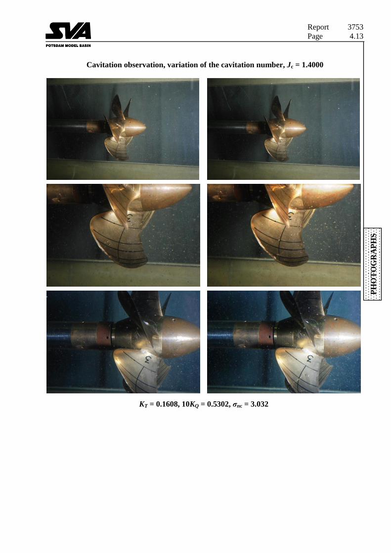
Cavitation observation, variation of the cavitation number, Jc = 1.4000
KT = 0.1608, 10KQ = 0.5302, σnc = 3.032

Report 3753
Page 4.14
PH
OT
OG
RA
PH
S
Cavitation observation, variation of the cavitation number, Jc = 1.4000
KT = 0.1362, 10KQ = 0.4890, σnc = 2.022
Report 3753
Page A1.1
AN
NE
X
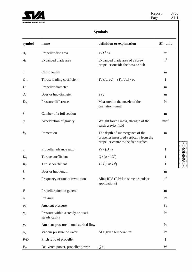
Symbols
symbol name definition or explanation SI - unit
A0 Propeller disc area π D 2 / 4 m
2
AE Expanded blade area Expanded blade area of a screw
propeller outside the boss or hub
m2
c Chord length m
CTh Thrust loading coefficient T / (AP qA) = (TP / AP) / qA 1
D Propeller diameter m
dh Boss or hub diameter 2 rh m
DH2 Pressure difference Measured in the nozzle of the
cavitation tunnel
Pa
f Camber of a foil section m
g Acceleration of gravity Weight force / mass, strength of the
earth gravity field
m/s2
h0 Immersion The depth of submergence of the
propeller measured vertically from the
propeller centre to the free surface
m
J Propeller advance ratio VA / (D n) 1
KQ Torque coefficient Q / (ρ n2 D
5) 1
KT Thrust coefficient T / ((ρ n2 D
4) 1
lh Boss or hub length m
n Frequency or rate of revolution Alias RPS (RPM in some propulsor
applications)
s-1
Ρ Propeller pitch in general m
p Pressure Pa
pA Ambient pressure Pa
pC Pressure within a steady or quasi-
steady cavity
Pa
p0 Ambient pressure in undisturbed flow Pa
pV Vapour pressure of water At a given temperature! Pa
P/D Pitch ratio of propeller 1
PD Delivered power, propeller power Q ω W

Report 3753
Page A1.2
AN
NE
X
Symbols
symbol Name definition or explanation SI - unit
Q Torque PD / ω Nm
q Dynamic pressure, density of kinetic
flow energy,
ρ V²/ 2 Pa
R Radius m
r Radius m
Re Reynolds number 22
7070 nD.V/cRe
.
1
rh Hub radius m
T Propeller thrust N
tW Temperature of water °C
tA Temperature of air
t Blade section thickness m
V Velocity of a body, speed in general of
the model or the ship
m/s
VA Advance speed of propeller Equivalent propeller open water speed
based on thrust or torque identity
m/s
VS Ship speed m/s
w Wake fraction in general w = 1 - VA / V 1
wa Wake fraction in axial direction wa = 1 - VA / V 1
Z, z Number of propeller blades 1
a Solved gas content mg/l
aS Solved gas content at saturation mg/l
Angle of rake deg
ηO Propeller efficiency in open water PT / PD = T VA / (Q ω) all quantities
measured in open water tests
1
θ Angle of propeller blade position deg
θEXT Skew angle extent The difference between maximum and
minimum local skew angle
deg

Report 3753
Page A1.3
AN
NE
X
Symbols
symbol name definition or explanation SI - unit
λ Scale ratio, linear scale of ship model Ship (index S) dimension divided by
corresponding model (index M)
dimension
λ = LS / LM = BS / BM = TS / TM
1
v Kinematic viscosity μ / ρ m2/s
π Circular constant 3.1415926535 1
ρ Mass density of fluid dm / dV kg/m3
φ Pitch angle of screw propeller arctg (P / (2 π R)) 1
σ Cavitation number (pA - pC) / q 1
σn Cavitation number calculated with n (p0 - pV) / (ρ/2·n2·D
2) 1
σV Cavitation number calculated with V (pA+·g h0–pV) / (ρ/2·V2) 1
σ0.7 Cavitation number calculated with the
resulting speed at r/R = 0.7
(pA+·g h0–pV) / (ρ/2·(V+0.7·n·D)2) 1
ω Circular frequency 2 π f 1/s
ω Propeller rotational velocity 2 π n 1/s
Indices
index Name definition or explanation
A Air
c Velocity correction by Glauert
method
c Construction, design
M Model
S Ship
max Maximum
min Minimum
V Venturi
W Water
0.7 Related radius r/R = 0.7

Report 3753
Page A1.4
AN
NE
X
Description of the cavitation appearance
code definition or explanation
BPSC Begin pressure side cavitation
BRC Begin root cavitation
BSSC Begin suction side cavitation
BTVC Begin tip vortex cavitation
EPSC End of pressure side cavitation
ESSC End of suction side cavitation
ETVC End of tip vortex cavitation
FC Foam cavitation
PS Pressure side
PSC Pressure side cavitation
SS Suction side
SSC Suction side cavitation
TVC Tip vortex cavitation
TD Thrust deduction

Report 3753
Page A2.1
AN
NE
X
Methods and formulas
Open water test in the cavitation tunnel
The open water tests were carried out with the dynamometer J25 from Kempf & Remmers in the
cavitation tunnel K15A. The influence of the test section on the propeller coefficients was
corrected with the method from Glauert.
Measuring values: T, Q, n, V, p
with Glauert correction
Advance coefficient Dn
VJ
Dn
VJ c
c
Thrust coefficient 42 Dn
TKT
Torque coefficient 52 Dn
QKQ
Propeller efficiency Q
T
K
KJ
h
2O
Q
T
K
KJ
h
2
c
Oc
Reynolds number 2270 70 nD.Vc
Re .
22
c
70
c70 nD.V
cRe .
Thrust loading coefficient 2
8
J
KC T
Th
2
c
c
8
J
KC T
Th
Cavitation numbers 2
stat
2V
ppv
V
s
2
statc
2c
v
Vc
V
pp
s
2
stat
2Dn
ppv
n
s
2
statc
2Dn
ppv
nc
s
2stat
70
702
Dn.V
ppv
.
s
2statc
70
702
Dn.V
pp
c
v
c.
s

Report 3753
Page A2.2
AN
NE
X
Procedure of cavitation tests in the cavitation tunnel
The conditions for cavitation tests are chosen such that the average loading of the propeller is
equal on model and full-scale.
As a measure for the propeller load in homogeneous inflow the tip speed ratio of the full-scale
propeller is used.
λ-identity λM = λS with A
π
V
Dn
J-identity JM = JS with A
V
DnJ
In addition the pressure is adjusted to such a level that model and full size cavitation numbers are
equal at corresponding points in the propeller disc.
s-identity sVM = sVS
For an arbitrary point at an immersion h0 the propeller cavitation number is:
2
0VA
50 V.
hgppV
s
For the cavitation tunnel the inflow speed VM of the propeller is chosen within practical limits
related to the tunnel capacity, the particular test set-up and the ranges of static pressure to be
adjusted. Requiring equal cavitation numbers on model and full-scale then leads to the pressure
to be adjusted in the cavitation tunnel. Obviously, at only one horizontal level the condition of
equal cavitation numbers can be fulfilled.

Report 3753
Page A2.3
AN
NE
X
Definition of the kind of cavitation in the drawings
Sheet cavitation
Usually thin, smooth,
transparent.
Initiating near leading
edge.
Often foamy in
appearance.
Vortex
cavitation
Trailing, detached
tip vortex
cavitation incepts
downstream of the
blade tip.
Foam cavitation
Sheet cavitation,
foamy in appearance.
Spot cavitation
Streak cavitation
Special form of bubble
cavitation, narrow,
usually forms in
parallel at isolated
roughness spots or
imperfections on the
blade surface or at the
leading edge.
Bubble cavitation
Small bubble type
cavitation indicative
of propellers with no
suction peaks at the
leading edge.
Cloud cavitation
Usually develops from
the break-up of
unsteady sheet
cavitation.
Report 3753
Page A2.4
AN
NE
X
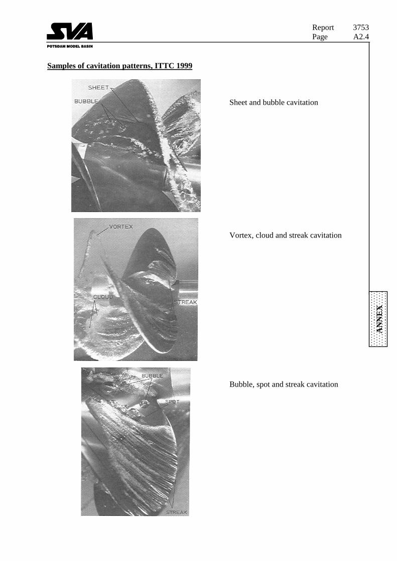
Samples of cavitation patterns, ITTC 1999
Sheet and bubble cavitation
Vortex, cloud and streak cavitation
Bubble, spot and streak cavitation

Report 3753
Page A3.1
AN
NE
X
Coordinate system
Cartesian coordinate system
Cylindrical propeller coordinate system looking on pressure side


