Post Tension M SERIES ACTIVE ANCHORAGES 2015-Rev · Post tensioning applications Post Tension M...
8
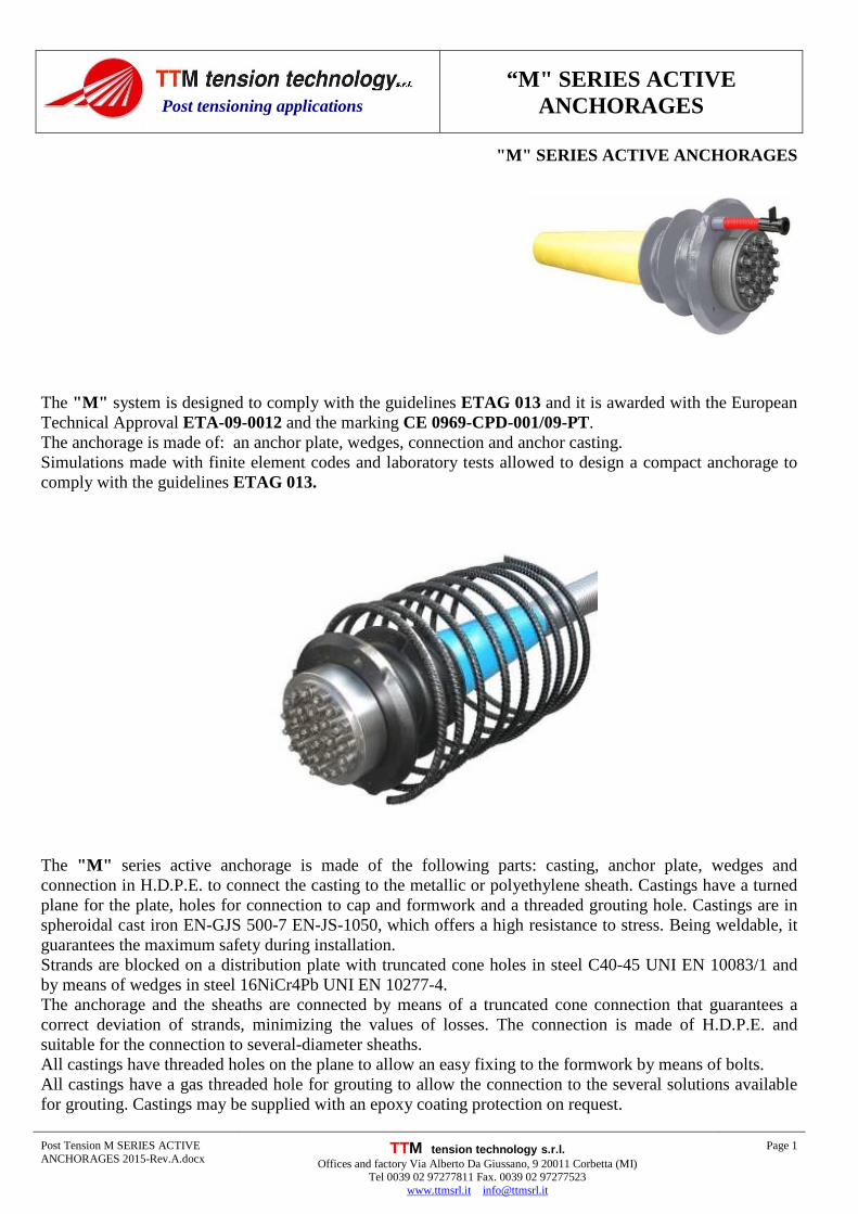
“M" SERIES ACTIVE ANCHORAGES Post Tension M SERIES ACTIVE ANCHORAGES 2015-Rev.A.docx TTM tension technology s.r.l. Offices and factory Via Alberto Da Giussano, 9 20011 Corbetta (MI) Tel 0039 02 97277811 Fax. 0039 02 97277523 www.ttmsrl.it [email protected] Page 1 Post tensioning applications "M" SERIES ACTIVE ANCHORAGES The "M" system is designed to comply with the guidelines ETAG 013 and it is awarded with the European Technical Approval ETA-09-0012 and the marking CE 0969-CPD-001/09-PT. The anchorage is made of: an anchor plate, wedges, connection and anchor casting. Simulations made with finite element codes and laboratory tests allowed to design a compact anchorage to comply with the guidelines ETAG 013. The "M" series active anchorage is made of the following parts: casting, anchor plate, wedges and connection in H.D.P.E. to connect the casting to the metallic or polyethylene sheath. Castings have a turned plane for the plate, holes for connection to cap and formwork and a threaded grouting hole. Castings are in spheroidal cast iron EN-GJS 500-7 EN-JS-1050, which offers a high resistance to stress. Being weldable, it guarantees the maximum safety during installation. Strands are blocked on a distribution plate with truncated cone holes in steel C40-45 UNI EN 10083/1 and by means of wedges in steel 16NiCr4Pb UNI EN 10277-4. The anchorage and the sheaths are connected by means of a truncated cone connection that guarantees a correct deviation of strands, minimizing the values of losses. The connection is made of H.D.P.E. and suitable for the connection to several-diameter sheaths. All castings have threaded holes on the plane to allow an easy fixing to the formwork by means of bolts. All castings have a gas threaded hole for grouting to allow the connection to the several solutions available for grouting. Castings may be supplied with an epoxy coating protection on request.
Transcript of Post Tension M SERIES ACTIVE ANCHORAGES 2015-Rev · Post tensioning applications Post Tension M...
“M" SERIES ACTIVE ANCHORAGES
Post Tension M SERIES ACTIVE ANCHORAGES 2015-Rev.A.docx
TTM tension technology s.r.l. Offices and factory Via Alberto Da Giussano, 9 20011 Corbetta (MI)
Tel 0039 02 97277811 Fax. 0039 02 97277523 www.ttmsrl.it [email protected]
Page 1
Post tensioning applications
"M" SERIES ACTIVE ANCHORAGES
The "M" system is designed to comply with the guidelines ETAG 013 and it is awarded with the European Technical Approval ETA-09-0012 and the marking CE 0969-CPD-001/09-PT. The anchorage is made of: an anchor plate, wedges, connection and anchor casting. Simulations made with finite element codes and laboratory tests allowed to design a compact anchorage to comply with the guidelines ETAG 013.
The "M" series active anchorage is made of the following parts: casting, anchor plate, wedges and connection in H.D.P.E. to connect the casting to the metallic or polyethylene sheath. Castings have a turned plane for the plate, holes for connection to cap and formwork and a threaded grouting hole. Castings are in spheroidal cast iron EN-GJS 500-7 EN-JS-1050, which offers a high resistance to stress. Being weldable, it guarantees the maximum safety during installation. Strands are blocked on a distribution plate with truncated cone holes in steel C40-45 UNI EN 10083/1 and by means of wedges in steel 16NiCr4Pb UNI EN 10277-4. The anchorage and the sheaths are connected by means of a truncated cone connection that guarantees a correct deviation of strands, minimizing the values of losses. The connection is made of H.D.P.E. and suitable for the connection to several-diameter sheaths. All castings have threaded holes on the plane to allow an easy fixing to the formwork by means of bolts. All castings have a gas threaded hole for grouting to allow the connection to the several solutions available for grouting. Castings may be supplied with an epoxy coating protection on request.

Post tensioning applications
Post Tension M SERIES ACTIVE ANCHORAGES 2015-Rev.A.docx
Page 2
45 MPa CONCRETE CLASS
Type Ultimate load for cable A B C D E F G H I L T15 T15S T15C
259 kN 279 kN 307 kN (mm) (mm) (mm) (mm) (mm) (mm) (mm) (mm) (mm) (mm)
4M15 1036 1116 1228 160 105 103 300 180 170 45/50 45 12 45
7M15 1813 1953 2149 200 125 133 340 250 220 62/67 45 12 45
9M15 2331 2511 2763 235 146 163 380 250 250 72/77 45 14 45
12M15 3108 3348 3684 265 160 180 385 300 300 80/85 50 16 45
15M15 3885 4185 4605 290 176 197 405 350 355 85/90 50 16 45
19M15 4921 5301 5833 320 200 215 430 425 400 95/100 50 16 56
22M15 5698 6138 6754 355 230 260 430 425 420 100/105 50 18 61
27M15 6993 7533 8289 380 250 277 470 400 460 110/115 50 18 70
L C D
ØA
ØB
EH
ØI
ØFG
ØA

Post tensioning applications
Post Tension M SERIES ACTIVE ANCHORAGES 2015-Rev.A.docx
Page 3
35 MPa CONCRETE CLASS
L C D
ØA
ØB
E
H
ØI
ØFG
ØA
Type Ultimate load for cable A B C D E F G H I L T15 T15S T15C
259 kN 279 kN 307 kN (mm) (mm) (mm) (mm) (mm) (mm) (mm) (mm) (mm) (mm)
4M15 1036 1116 1228 160 105 103 300 205 180 45/50 45 12 45
7M15 1813 1953 2149 200 125 133 340 270 240 62/67 45 12 45
9M15 2331 2511 2763 235 146 163 380 270 300 72/77 45 14 45
12M15 3108 3348 3684 265 160 180 385 350 350 80/85 50 16 45
15M15 3885 4185 4605 290 176 197 405 450 410 85/90 50 16 45
19M15 4921 5301 5833 320 200 215 430 450 440 95/100 50 16 56
22M15 5698 6138 6754 355 230 260 430 425 480 100/105 50 18 61
27M15 6993 7533 8289 380 250 277 470 480 530 110/115 50 18 70

Post tensioning applications
Post Tension M SERIES ACTIVE ANCHORAGES 2015-Rev.A.docx
Page 4
CONNECTION TO THE FORMWORK FOR M ANCHORAGES
Type 4M15 7M15 9M15 12M15 15M15 19M15 22M15 27M15 A 160 200 235 265 290 320 355 380 B 103 133 163 180 197 215 260 277 C 124 145 190 203 235 237 290 325 D M10 M10 M10 M12 M12 M12 M16 M16 α 180° 120° 120° 120° 120° 120° 120° 120°
Quantity 2 3 3 3 3 3 3 3
RECESSES FOR M ANCHORAGES
Type 4M15 7M15 9M15 12M15 15M15 19M15 22M15 27M15 A 160 200 235 265 290 320 355 380
B x B 200x200 240x240 275x275 305x305 330x330 360x360 395x395 420x420 C 110 110 110 110 110 125 130 140 α 15 15 15 15 15 15 15 15
α
α
ØCB
ØD
ØA
C
ØA
BxB
ØA
BxB
α°
α°
Post tensioning applications
Post Tension M SERIES ACTIVE ANCHORAGES 2015-Rev.A.docx
Page 5
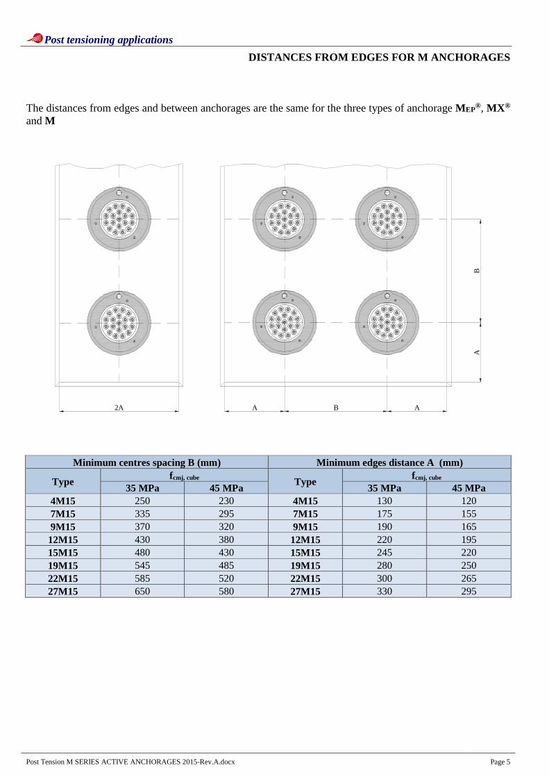
DISTANCES FROM EDGES FOR M ANCHORAGES The distances from edges and between anchorages are the same for the three types of anchorage MEP®, MX ® and M
A2A
BA
B A
Minimum centres spacing B (mm) Minimum edges distance A (mm)
Type fcmj, cube Type
fcmj, cube 35 MPa 45 MPa 35 MPa 45 MPa
4M15 250 230 4M15 130 120 7M15 335 295 7M15 175 155 9M15 370 320 9M15 190 165 12M15 430 380 12M15 220 195 15M15 480 430 15M15 245 220 19M15 545 485 19M15 280 250 22M15 585 520 22M15 300 265 27M15 650 580 27M15 330 295

Post tensioning applications
Post Tension M SERIES ACTIVE ANCHORAGES 2015-Rev.A.docx
Page 6
UNBONDED POST-TENSIONING ON "M" ANCHORAGES The unbonded post-tensioning with M, M EP® and MX ® anchorages is carried out by using unbonded, greased and plastic-coated strands, which are restrained in a mortar grouting with a rubber buffer and allow their following tensioning and the covering with grease of all the parts of the anchorage that are subject to corrosion, such as: anchorage block, wedges and strand are restrained in grease.
The rubber buffer allows to restrain grouting at half anchorage as well as the strand tightness on the polyethylene coating. Once the cable grouting is over, the buffer can be removed. The void obtained inside the anchorage allows to protect the under plate strands and shall be filled with grease. The strand by strand coating of the free whips must be removed following the procedures, the anchor plate must be removed, tensioning must be carried out and the protection cap, which is filled with grease, must be installed.
Grouting with vent placed on the truncated cone reduction in polyethylene.
Insertion of greased and polyethylene-covered strands into the anchorage. The restraining buffer allows to carry out the cable grouting before installing the anchor plate to block the strands.
Post tensioning applications
Post Tension M SERIES ACTIVE ANCHORAGES 2015-Rev.A.docx
Page 7
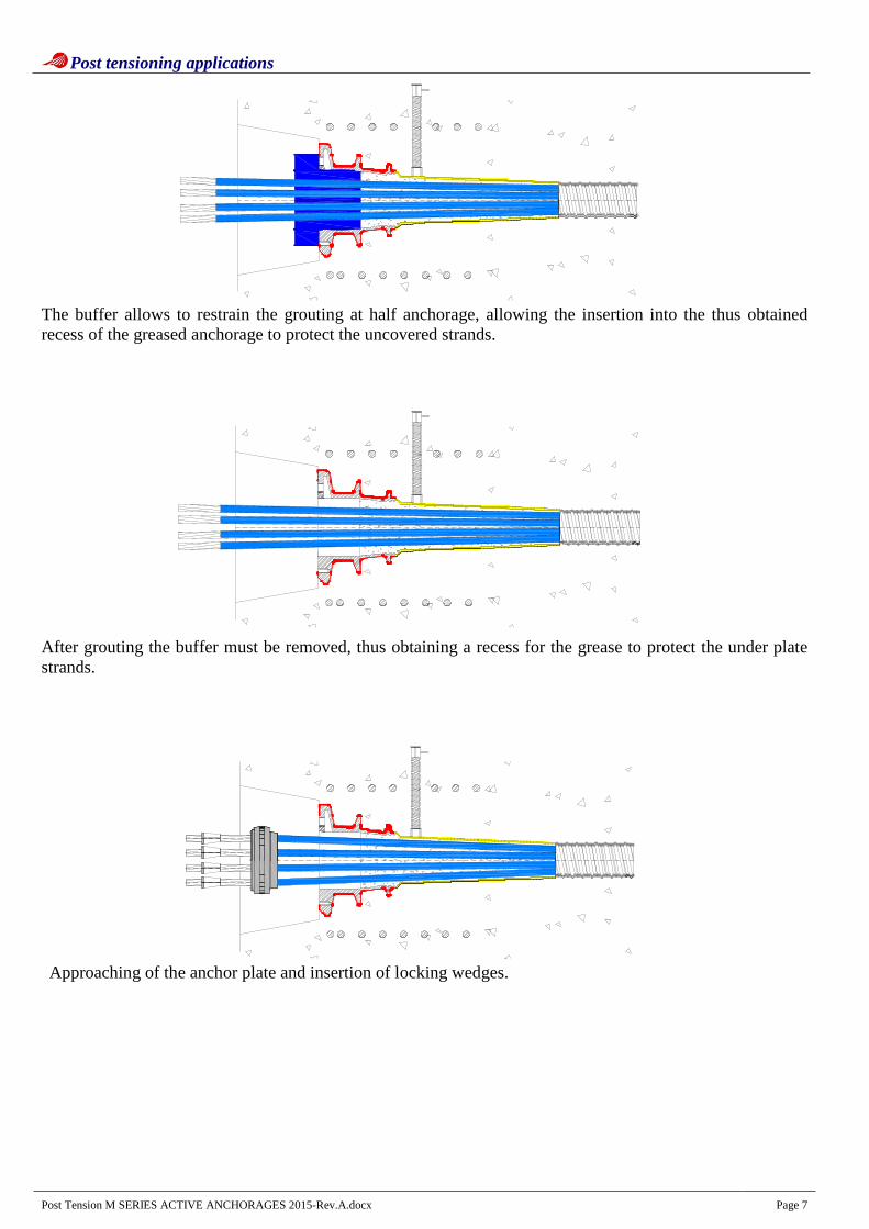
The buffer allows to restrain the grouting at half anchorage, allowing the insertion into the thus obtained recess of the greased anchorage to protect the uncovered strands.
After grouting the buffer must be removed, thus obtaining a recess for the grease to protect the under plate strands.
Approaching of the anchor plate and insertion of locking wedges.
Post tensioning applications
Post Tension M SERIES ACTIVE ANCHORAGES 2015-Rev.A.docx
Page 8
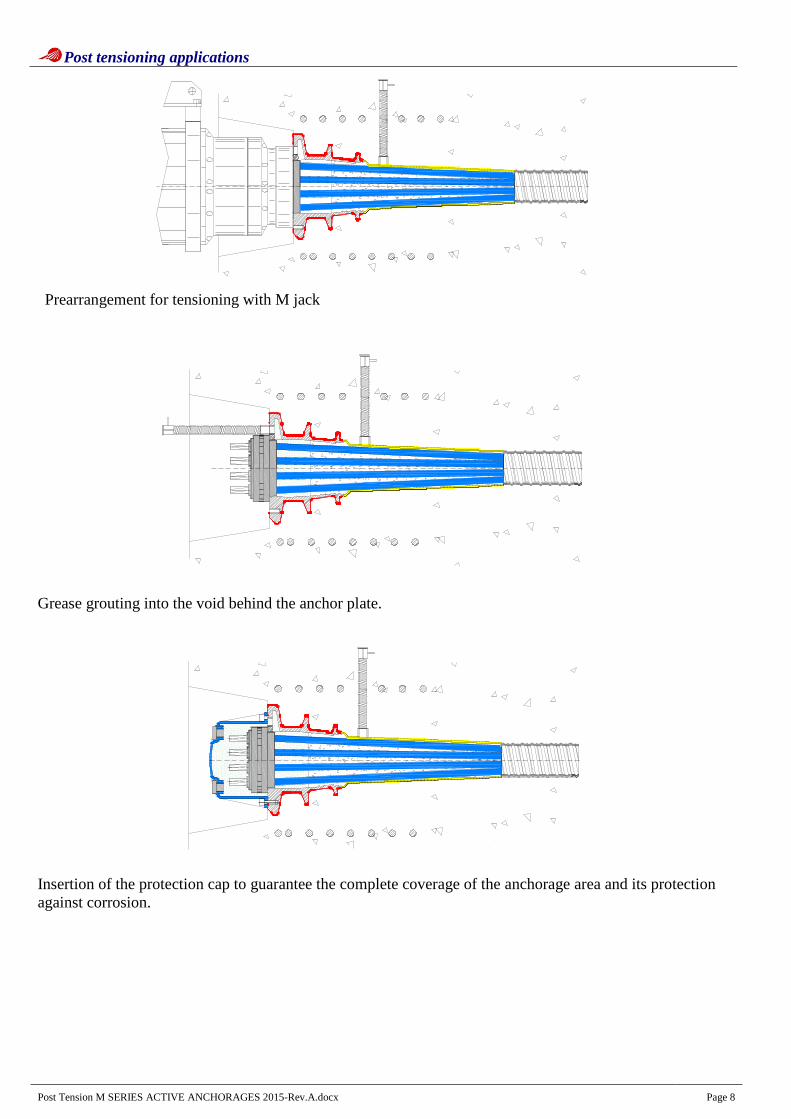
Prearrangement for tensioning with M jack
Grease grouting into the void behind the anchor plate.
Insertion of the protection cap to guarantee the complete coverage of the anchorage area and its protection against corrosion.