Post-processing J.Cugnoni, LMAF/EPFL, 2009. Finite element « outputs » Essential variables: ...
23
Post-processing J.Cugnoni, LMAF/EPFL, 2009
-
Upload
david-brown -
Category
Documents
-
view
216 -
download
1
Transcript of Post-processing J.Cugnoni, LMAF/EPFL, 2009. Finite element « outputs » Essential variables: ...

Post-processing
J.Cugnoni, LMAF/EPFL, 2009

Finite element « outputs » Essential variables:
Displacement u, temperature T
find u such that : K u = f
Natural variables : Stress , heat flux q Directly related to (derivatives of) essential variables
by the constitutive relationship in linear problems
Derived variables : Like strain = u, strain energy density, enthalpy

FE results: type & localization
Data types: Scalars (T): 1 component Vectors (u): 3 components + magnitude 2nd order tensors (): 6 components if symm. + invariants (von
Mises, max. principal, hydrostatic)
Localization: Unique Nodal values Element Nodal values Gauss (integration) points values Element centroid

Displacement – Strain post processing
Nodal displacement u (unique nodal val., essential var.)
Shape functions & derivatives at integration pt of the element
=> B matrix
Strain tensor at integration pt = eB u
Unique Nodal value
Element Integration pt
Shape functions and derivatives are only evaluated at integ. pts

Stress calculation at integration pts (linear elasticity)
Constitutive relationship of element e=> eC matrix
Stress tensor at integration pt i of element e: ei = eC ei
Element Integration pt
Element-wise constitutive relation
Strain tensor at integration pt i of element e: ei = eB eu
Element Integration pt

From integration pts to unique nodal values
Stress tensor at nodal pt kof the global mesh: k
Shape functions or other extrapolation functions
Stress tensor at integration pt i of the element e: ei
Unique Nodal value
Element Integration pt
Stress tensor at nodal pt j of the element e: ej
Weighted (or conditionnal)averaging
Element Nodal value

FE results in Abaqus Field output:
A snapshot of the values at all points in the model for a given time
History output: A « time curve » for a single variable at a given point
over time In STEP module:
Specify which variables must be computed in field output & history outputs
Can specify a « frequency » to reduce the output size For history output, you need to define a « set » to
extract time evolution of given points / elements

Example: open thermoMecaExo1Correct.cae Select to Model-1-Transient In Step module:
Edit existing Field output: Add all Energy outputs, add Forces-> NFORC Add Thermal outputs NFLUX & HFLA (heat flux * area)
History outputs: Tool -> Set -> Create : create a set of points for history output Create a new history output Domain=Set, Output: Thermal->NT (nodal temperature)
Run the Job « thermoMecaTransient »
Video: PostProDemo1.swf

FE result visualization in Abaqus Field outputs:
Select in Results -> Field outputsSelect the desired output time (Step & Frame)Contour plot:
colormap + deformed shapeSymbol plot:
to display vectors or principal tensor componentsOther features:
Cutting planes, display groups A lot of options to customize display

Result localization in Abaqus Abaqus Standard solver stores only necessary results in
ODB files: Essential variables : unique nodal values Natural variables: only at integration points Derived variables: localized where in makes sense
Abaqus CAE / visualization module can « extrapolate » some results at other locations Example: evaluate unique nodal stresses from integration points You can control the extrapolation in Results -> Option.. View « discontinuities » to identify « strong gradient » (=low
accuracy) regions of your mesh

Example (open thermoMecaTransient.odb): Contour plots of stress field, select time = 2000 s:
Select Mises, S33, Max. Principal components Change Visualization options (deformation scale factor, colormap
range, edges) Cutting plane
Results Options (select Mises stress): Disable averaging, look at element nodal values, notice the
discontinuities. Enable averaging, change the averaging threshold (0% -> 100%) Display discontinuities, notice regions of large discontinuities: sharp
corners = stress singularities !! Symbol plot:
Use display group to isolate a region View principal stress tensor and displacements
Video PostProDemo2.swf

Extracting values at node / element Select Field output, activate Contour plot
Use Tools->Query->Probe Value Select Probe = Element or Probe = Node Select result localization (for elements only)
Integration pts, Centroid, Element nodal
Activate the desired results in the table Pick a node / element to add it to the list Can write the table values to a text file: write

Example: Extract different stress values (int. pt, elem. nodal,
averaged nodal) at a given point
Video: PostProDemo3.swf
Extracting curves in Abaqus Path = spatial curve to « cut the model »:
Use Tools -> Path -> Create to generate Generation method:
Node list: pick nodes to define a polyline Point list: enter coordinates of polyline vertices Edge list: select element edges = efficient !! Circular: select points to generate a circle
To plot / save the curve: Use Tools -> XY data -> Create
Select source = Path Choose the path choose configuration = « undeformed » activate include intersection Generate the curve & save it for later use
Example: Define a linear path based on 2 nodes Define a path along edges with « feature edge » or
« shortest distance » option Define a circular path by 3 points Extract curves of Mises Stress distribution along each
path, save XY data Plot all XY curves
Video: PostProDemo4.swf

Extracting curves in Abaqus Time evolution curves :
From Field outputs: Use Tools -> XY data -> Create Choose source = Field Output Select result localization (integ pt, nodal, …) Select result to extract Pick elements or nodes from 3D view Plot and save if necessary
From History outputs: Use Tools -> XY data -> Create Choose source = History output Select the desired history output, plot and save

Example: Extract time evolution curves of the temperature at
some nodes Extract time evolution curves of the Mises stress at
for different type of result localization Plot all XY curves
Video: PostProDemo5.swf
Exporting data from Abaqus
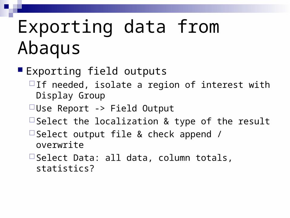
Exporting field outputs If needed, isolate a region of interest with
Display GroupUse Report -> Field OutputSelect the localization & type of the resultSelect output file & check append / overwriteSelect Data: all data, column totals, statistics?

Exporting data from Abaqus
Exporting XY curvesCreate XY data and save itUse Report -> XYSelect the XY curvesSelect output file & check append / overwriteSelect Data: all data, column totals, statistics?

Example: Use Report-> Field Output to extract the min, max
and average nodal temperature in a Text file Create a XY curve of the time evolution of the
temperature at one point and export it to another text file
Video: PostProDemo6.swf

Extracting images & movies Image capture / printing:
File -> Print Choose Destination = Printer or File If File, choose format (PNG for example) and file name
Movies: Enter an animation mode:
Animate -> Time History / Scale Factor / Harmonic Use Animate -> Save As to generate movie
Select destination file and format Set Options to choose the level of compression Choose display option (background ?) Set frame rate to ~5 image/s

Example: Extract an image of Mises stress field at
t=2000s showing the min & max valuesExtract a movie of the time evolution of the
temperature in the model
Video: PostProDemo7.swf

Advanced post-processing
Calculate new fields: If necessary, create a new coordinate system: Tools -> Coord.
System -> Create Run Tools -> Create Field outputs -> From fields
Pick a time: Step & Increment Enter an expression in the « calculator »:
Pick operators & operands (fields) in the list The new result will be « save » in memory only in a temporary
Step called « Session Step » You can use this tool to evaluate quantities in different
coordinate systems (for example stress in cylindrical coordinates)


![· Translate this pageÐÏ à¡± á> þÿ ìñu òu îu u u u u u u u u u u u u u u u u u u u u u u u u u u u u u u u u u!u"u#u$u%u&u'u(u)u*u+u,u-u.u/u0u1u2u3u4u5u6u7u8u9u:u;u u?u@uAuBuCuDuEuFuGuHuIuJuKuLuMuNuOuPuQuRuSuTuUuVuWuXuYuZu[u\u]u^u_u](https://static.fdocuments.net/doc/165x107/5b23e7017f8b9a25128b4957/-translate-this-pagedi-a-a-by-inu-ou-iu-u-u-u-u-u-u-u-u-u-u-u.jpg)