
Position Sensor Simulation with ANSYS ® Maxwell 3D
30
Position Sensor Simulation with ANSYS ® Maxwell 3D Dr. Leon Voss (ANSYS Germany) Jens Otto PRACE Autumn School 2013 - Industry Oriented HPC Simulations, September 21-27, University of Ljubljana, Faculty of Mechanical Engineering, Ljubljana, Slovenia
Transcript of Position Sensor Simulation with ANSYS ® Maxwell 3D
Position Sensor Simulation
with
ANSYS ® Maxwell 3D Dr. Leon Voss (ANSYS Germany)
Jens Otto
PRACE Autumn School 2013 - Industry Oriented HPC Simulations, September
21-27, University of Ljubljana, Faculty of Mechanical Engineering, Ljubljana,
Slovenia

© 2013 CADFEM GmbH
ANSYS Maxwell: Sensor Applications
- 1 -
Hall Effect
• Velocity、Position
Variable Reluctance
• Velocity、Position
Magnetic Resistance
• Velocity、Position
Flux Gate
• Proximity Sensing
• Navigation
• Velocity、Position
Eddy Current
• NDT(flaw detection)

© 2013 CADFEM GmbH
Maxwell 3D: Example Nonlinear Magnetostatic Analysis
- 2 -
Adaptive meshing for most
automated and precise analysis
Parametrized setup
Extended Postprocessing with fields
calculator
Hall Sensor Permanent
Magnet
Pole piece
IC chip
Cell
Top
Cell
Bot
© 2013 CADFEM GmbH
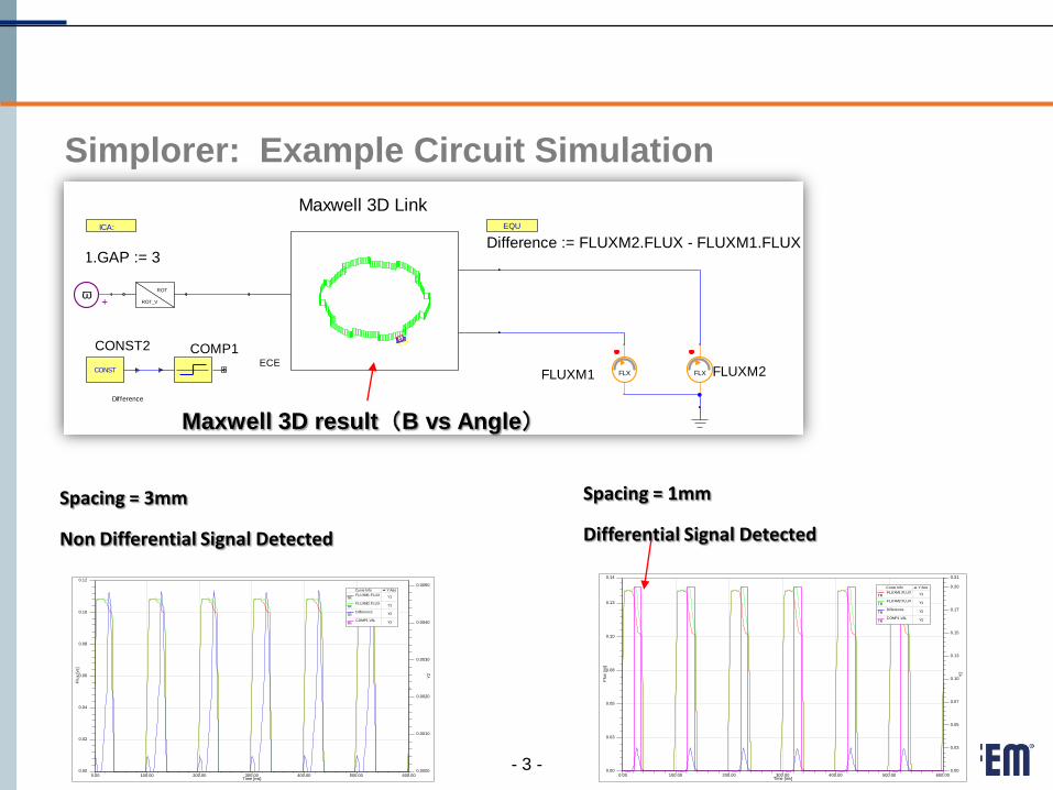
Simplorer: Example Circuit Simulation
- 3 -
ICA:
EMSSLink1.GAP := 3
EQU
Difference := FLUXM2.FLUX - FLUXM1.FLUX
FLXFLUXM1 FLX FLUXM2CONST
CONST2
Difference
COMP1ECE
EMSSLink1
ROT
ROT_Vw
+
Maxwell 3D LinkMaxwell 3D Link
0.00 100.00 200.00 300.00 400.00 500.00 600.00Time [ms]
0.00
0.02
0.04
0.06
0.08
0.10
0.12
Flu
x [
vs]
0.0000
0.0010
0.0020
0.0030
0.0040
0.0050
Y2
Curve Info Y Axis
FLUXM1.FLUXTR Y1
FLUXM2.FLUXTR Y1
DifferenceTR Y2
COMP1.VALTR Y2
0.00 100.00 200.00 300.00 400.00 500.00 600.00Time [ms]
0.00
0.02
0.04
0.06
0.08
0.10
0.12
Flu
x [
vs]
0.0000
0.0010
0.0020
0.0030
0.0040
0.0050
Y2
Curve Info Y Axis
FLUXM1.FLUXTR Y1
FLUXM2.FLUXTR Y1
DifferenceTR Y2
COMP1.VALTR Y2
Spacing = 3mm
Non Differential Signal Detected
0.00 100.00 200.00 300.00 400.00 500.00 600.00Time [ms]
0.00
0.03
0.05
0.08
0.10
0.13
0.14
Flu
x [
vs]
0.00
0.03
0.05
0.07
0.10
0.13
0.15
0.17
0.20
0.21
Y2
Curve Info Y Axis
FLUXM1.FLUXTR Y1
FLUXM2.FLUXTR Y1
DifferenceTR Y2
COMP1.VALTR Y2
EMSSLink1.GAP := 1
Spacing = 1mm
Differential Signal Detected
Maxwell 3D result(B vs Angle)
© 2013 CADFEM GmbH
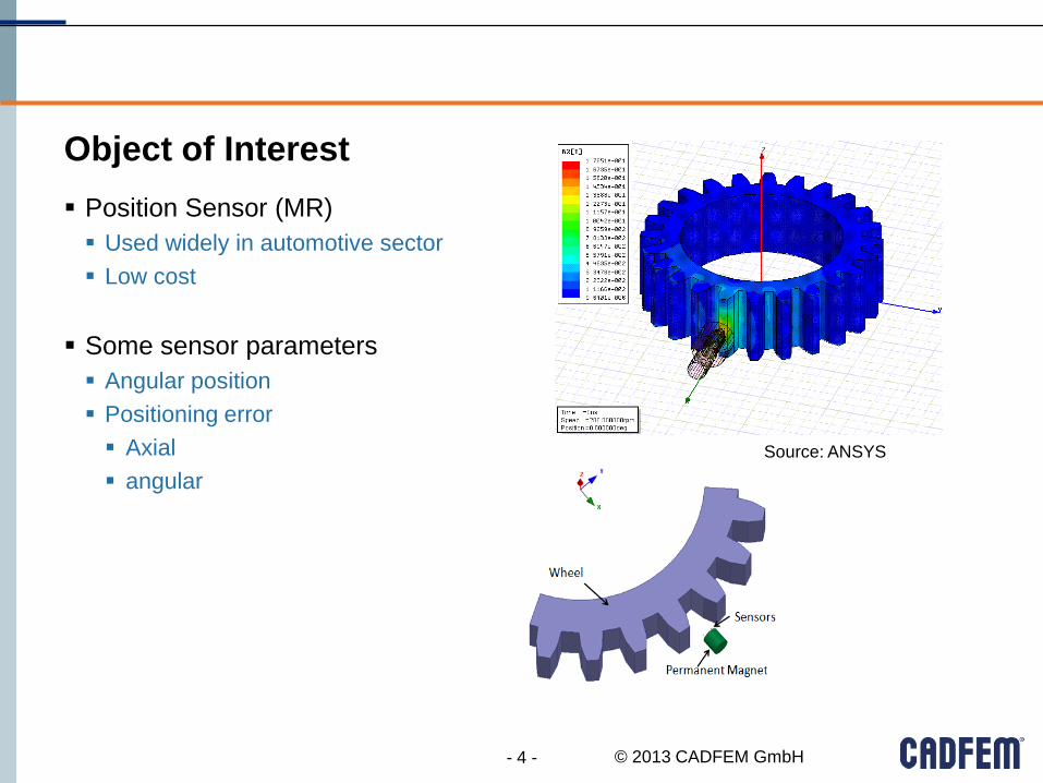
Object of Interest
- 4 -
Position Sensor (MR)
Used widely in automotive sector
Low cost
Some sensor parameters
Angular position
Positioning error
Axial
angular
Source: ANSYS

© 2013 CADFEM GmbH
Principle
- 5 -
• Magnetoresistive(MR) sensor element with gear wheel.
• Resistance changes with the angles which the magnetic field which crosses
• the direction of current accomplishes.
• Bridge connection of each resistance.
• No thermal effects.
• No deformation, eddy current effects.

© 2013 CADFEM GmbH
Maxwell: Process
Use Maxwell 3D MagnetoStatic +Optimetrics
Linear permeability for valid parameter.
Variable parameter about a gear rotation angle. Change rotation angle of object to a variable.
Integrate magnetic field intensity of a sensor object. Calculates using a function of Calculator.
Export Design Variation with Workbench Data is manually processed using a function of Table I/O.
6

© 2013 CADFEM GmbH
Maxwell: Simulation Details
Rotation angle of Wheel
Permeability of a deficit part
7
RotAngle
$TeethMur
Magnetize M
© 2013 CADFEM GmbH
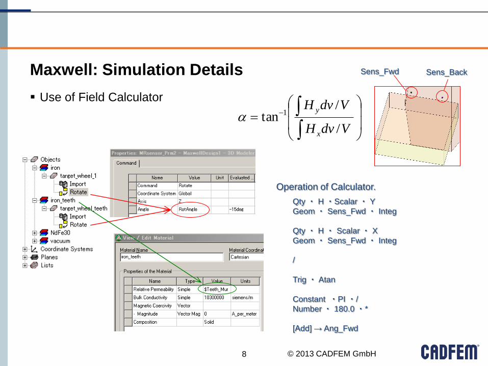
Maxwell: Simulation Details
Use of Field Calculator
8
Sens_Fwd Sens_Back
VdvH
VdvH
x
y
/
/tan 1
Qty ・ H ・Scalar ・ Y
Geom ・ Sens_Fwd ・ Integ
Qty ・ H ・ Scalar ・ X
Geom ・ Sens_Fwd ・ Integ
/
Trig ・ Atan
Constant ・PI ・/
Number ・ 180.0 ・*
[Add] → Ang_Fwd
Operation of Calculator.
© 2013 CADFEM GmbH
HANDS-ON
9
HANDS-ON-Position-Sensor-Simulation-with Maxwell3D.docx

© 2013 CADFEM GmbH
Workbench: Simulation Process
Efficient use of hardware resources for parameter variations
HPC parallel computation with ANSYS
Types of processing with ANSYS
Example scenario
10

© 2013 CADFEM GmbH
HPC parametric packs amplify
both solver licenses and HPC
licenses allowing you to
drastically reduce time to
innovation
Time reduction for a parametric study
- 11 -
ANSYS HPC Parametric Pack
dp1
dp2
dp3
dp4
Seri
es
of
De
sign
po
ints
Unused Cores
One set of solvers and 1 x HPC Parametric Pack
without HPC
94% reduced time to innovation
One set of Solver keys
Four sets of solver keys or
+ 1 HPC Pack

© 2013 CADFEM GmbH
Local
- 12 -
Types of Processing
Remote
1. All Processes Local
Geometry Update
Meshing Process
Boundary Conditions Mapping
Solution Process
Result Extraction
Result Processing
2. Local Pre/Post and Remote Solve Process
Geometry Update
Meshing Process
Boundary Conditions Mapping
Solution Process Result Extraction
Result Processing
3. Main Processes Remote
Geometry Update Meshing Process
Boundary Conditions Mapping
Solution Process
Result Extraction Result Processing

© 2013 CADFEM GmbH
Local
- 13 -
1. All Processes Local
Geometry Update
Meshing Process
Boundary Conditions Mapping
Solution Process Result Extraction
Result Processing
Remote

© 2013 CADFEM GmbH - 14 -
1. All Processes Local
All design points are calculated sequentially which means step by step
(NO simultaneous processes)
Solution Process:
Update Option: Use application default
Design Point Update Process:
Update Option: Run in Foreground
Local
Local
© 2013 CADFEM GmbH
Local
- 15 -
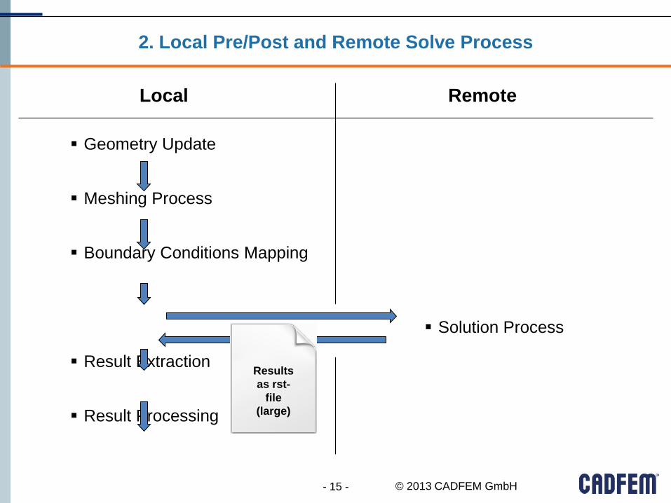
2. Local Pre/Post and Remote Solve Process
Geometry Update
Meshing Process
Boundary Conditions Mapping
Result Extraction
Result Processing
Remote
Solution Process
Results
as rst-
file
(large)

© 2013 CADFEM GmbH - 16 -
2. Local Pre/Post and Remote Solve Process
All design points are calculated sequentially which means step by step
(NO simultaneous processes)
Solution Process:
Update Option: Submit to Remote
Solve Manager
Design Point Update Process:
Update Option: Run in Foreground
Compute Server
Local

© 2013 CADFEM GmbH
Local
- 17 -
3. Main Processes Remote
Geometry Update
Result Processing
Remote
Meshing Process
Boundary Conditions Mapping
Solution Process
Result Extraction
extracted
Results
as table
(small)

© 2013 CADFEM GmbH
All design points are calculated sequentially or simultaneously
Processing order defined by 3 types of settings (see following slides)
- 18 -
3. Main Processes Remote
Solution Process:
Update Option: Use application default
Design Point Update Process:
Update Option: Submit to Remote
Solve Manager
Compute Server
Compute Server

© 2013 CADFEM GmbH
2nd Type: One Job Each Design Point
- 19 -
3. Main Processes Remote
Number of jobs is equal to design points
e. g. 32 design points 32 jobs
Jobs can be processed sequentially or simultaneously, depending on
licensing and RSM settings

© 2013 CADFEM GmbH
3rd Type: Specify Maximum Number of Jobs
- 20 -
3. Main Processes Remote
Maximum number of jobs is limited
Jobs can be processed sequentially or simultaneously, depending on
licensing and RSM setting
© 2013 CADFEM GmbH
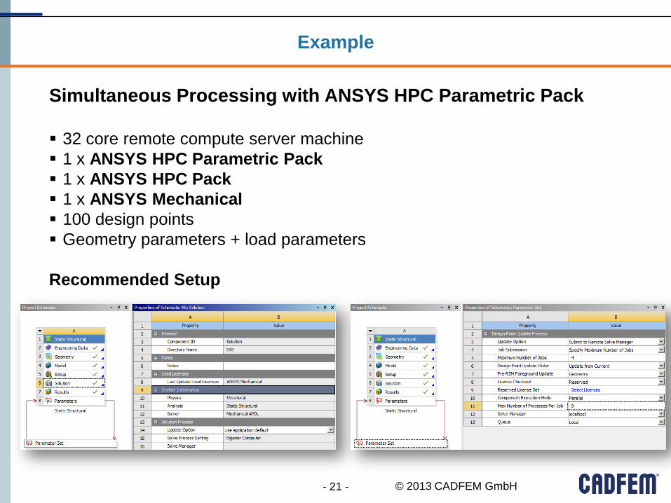
32 core remote compute server machine
1 x ANSYS HPC Parametric Pack
1 x ANSYS HPC Pack
1 x ANSYS Mechanical
100 design points
Geometry parameters + load parameters
Recommended Setup
Simultaneous Processing with ANSYS HPC Parametric Pack
- 21 -
Example

© 2013 CADFEM GmbH
Simultaneous Processing with ANSYS HPC Parametric Pack
- 22 -
Example
© 2013 CADFEM GmbH
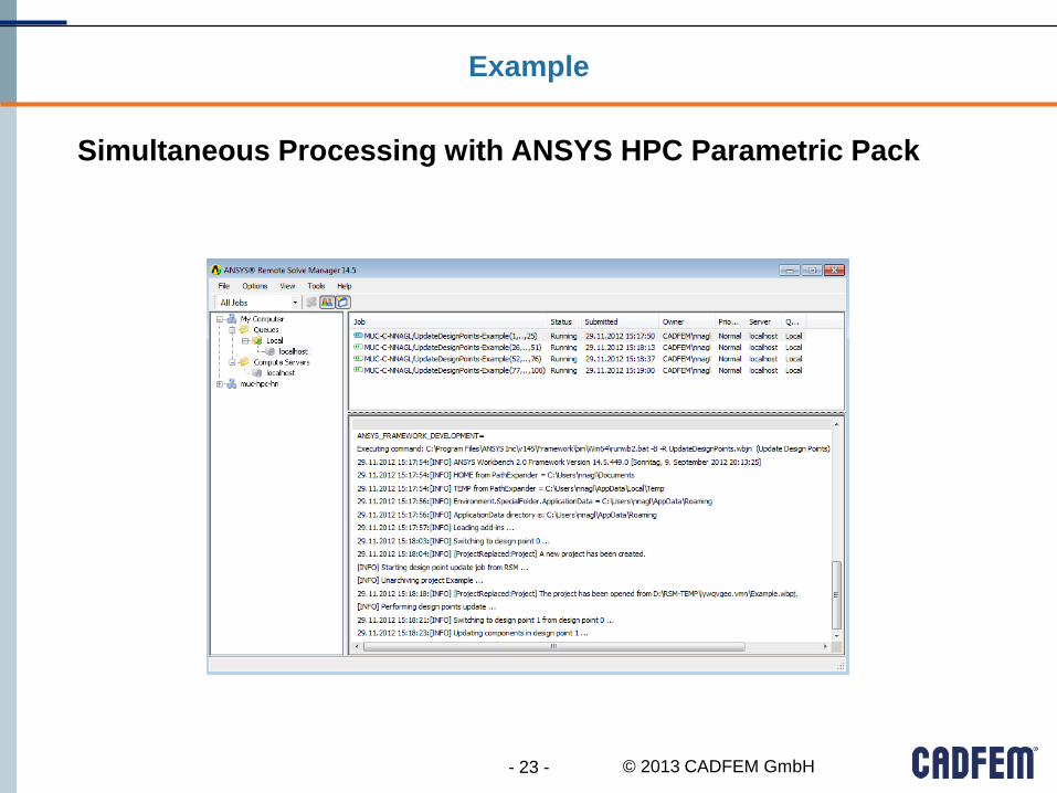
Simultaneous Processing with ANSYS HPC Parametric Pack
- 23 -
Example

© 2013 CADFEM GmbH
Simultaneous Processing with ANSYS HPC Parametric Pack
- 24 -
Example
Summary
Simultaneous processing enabled by
“Reserved Licenses”
Specified Maximum Number of Jobs: 4
ANSYS HPC Parametric Pack
All geometries are updated locally upfront
4 jobs in process (each job includes 25 design points), 0 jobs in RSM-Queue
8 cores per job 32 cores in process; enabled by ANSYS HPC Pack
Specified Maximum Number of Jobs < RSM Limiter Golden Rule

© 2013 CADFEM GmbH
ANSYS Maxwell: Integration into Workbench
- 25 -
© 2013 CADFEM GmbH
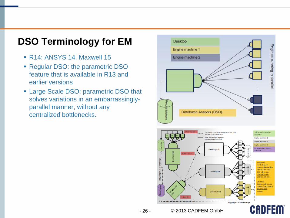
DSO Terminology for EM
- 26 -
R14: ANSYS 14, Maxwell 15
Regular DSO: the parametric DSO
feature that is available in R13 and
earlier versions
Large Scale DSO: parametric DSO that
solves variations in an embarrassingly-
parallel manner, without any
centralized bottlenecks.
© 2013 CADFEM GmbH 27
Additional Function: System Simulation
Motivation:
Include different physical effects
magnetic-thermal / cfd
magnetic-electric circuit
magnetic-mechanic
Use existing (detailed) know how including nonlinearity
Save simulation time
Share data between departments
© 2013 CADFEM GmbH
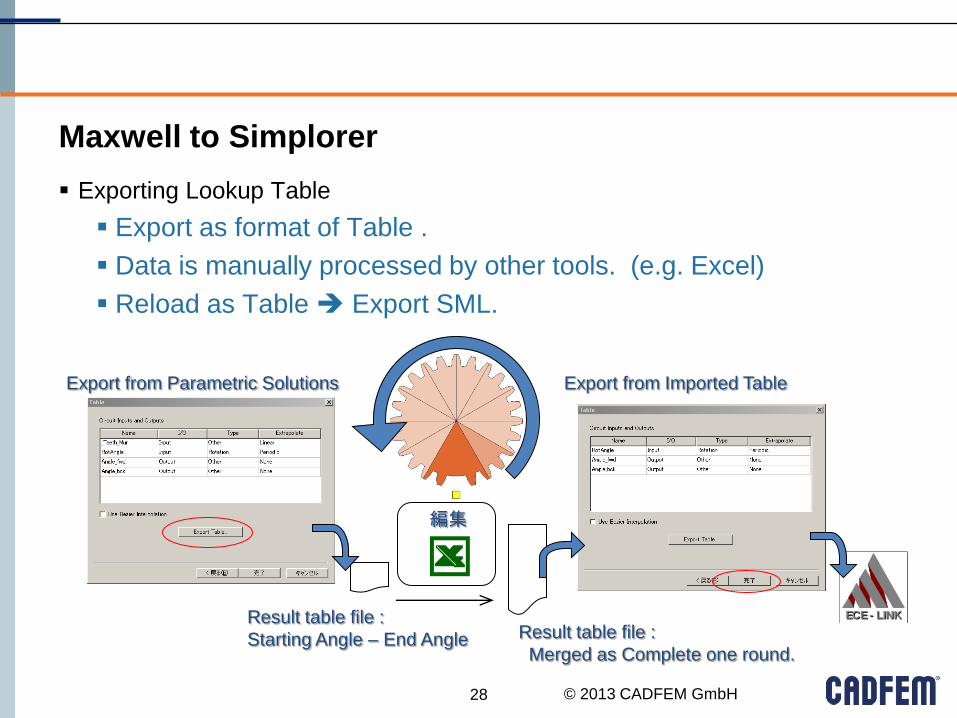
Maxwell to Simplorer
28
Exporting Lookup Table
Export as format of Table .
Data is manually processed by other tools. (e.g. Excel)
Reload as Table Export SML.
Export from Parametric Solutions Export from Imported Table
ECE - LINKECE - LINK
編集
Result table file :
Starting Angle – End Angle Result table file :
Merged as Complete one round.

© 2013 CADFEM GmbH
Simplorer: System Simulation (Overview)
29
-20.40m
20.40m
0
0 40.00m20.00m
MRSensor.Sensitivity
Sensor output Voltage.
28.00u
29.00u
28.50u
0 40.00m20.00m
VM1.V [V] + -2.50
-9.92
10.00
0
0 40.00m20.00m
VM6.V [V]
Amplified Output.