PORTABLE INDUSTRIAL OIL-FIRED RADIANT HEATERS
18
WARNING: This is a target infrared portable heater. It uses air (oxygen) from the area in which it is used. Provisions for adequate combustion and ventilation air must be provided. Refer to “FRESH AIR AND VENTILATION” on page 4. WARNING: Improper adjustment, alteration, service or maintenance can cause injury or property damage. Refer to this manual for correct installation and operational procedures. For Assistance or additional information consult a service agency. ENERCO GROUP, INC., 4560 W. 160 TH ST., CLEVELAND, OHIO 44135 · 866-447-2194 WARNING: If the information in this manual is not followed exactly, a fire or explosion may result causing property damage, personal injury, or loss of life. – Do not store or use gasoline or other flammable vapors and liquids in the vicinity of this or any other appliance. – Service must be performed by a service agency. HSP60R HSP125R/HSP150R PORTABLE INDUSTRIAL OIL-FIRED RADIANT HEATERS OPERATING INSTRUCTIONS AND OWNER’S MANUAL MODEL# HSP60R HSP125R HSP150R READ INSTRUCTIONS CAREFULLY: YOUR SAFETY IS IMPORTANT TO YOU AND TO OTHERS. Read and follow all instructions. Place instructions in a safe place for future reference. Do not allow anyone who has not read these instructions to assemble, light, adjust or operate the heater. NEVER LEAVE THE HEATER UNATTENDED WHILE BURNING! NEVER LEAVE THE HEATER UNATTENDED WHILE BURNING! NEVER LEAVE THE HEATER UNATTENDED WHILE BURNING!
Transcript of PORTABLE INDUSTRIAL OIL-FIRED RADIANT HEATERS

WARNING: This is a target infrared portable heater. It uses air (oxygen) from the area in which it is used. Provisions for adequate combustion and ventilation air must be provided. Refer to “FRESH AIR AND VENTILATION” on page 4.
WARNING: Improper adjustment, alteration, service or maintenance can cause injury or property damage. Refer to this manual for correct installation and operational procedures. For Assistance or additional information consult a service agency.
ENERCO GROUP, INC., 4560 W. 160TH ST., CLEVELAND, OHIO 44135 · 866-447-2194
WARNING: If the information in this manual is not followed exactly, a fire or explosion may result causing property damage, personal injury, or loss of life. – Do not store or use gasoline or other flammable vapors and liquids in the vicinity of this or any other appliance.
– Service must be performed by a service agency.
HSP60R HSP125R/HSP150R
PORTABLE INDUSTRIAL OIL-FIRED RADIANT HEATERS
OPERATING INSTRUCTIONS AND OWNER’S MANUAL
MODEL#HSP60R HSP125R
HSP150R
READ INSTRUCTIONS CAREFULLY: YOUR SAFETY IS IMPORTANT TO YOU AND TO OTHERS. Read and follow all instructions. Place instructions in a safe place for future reference. Do not allow anyone who has not read these instructions to assemble, light, adjust or operate the heater.
NEVER LEAVE THE HEATER UNATTENDED WHILE BURNING!NEVER LEAVE THE HEATER UNATTENDED WHILE BURNING!NEVER LEAVE THE HEATER UNATTENDED WHILE BURNING!
2 Installation Instructions and Owner’s ManualPortable Radiant Oil-Fired Industrial Heaters
NEVER LEAVE THE HEATER UNATTENDED WHILE BURNING!NEVER LEAVE THE HEATER UNATTENDED WHILE BURNING!NEVER LEAVE THE HEATER UNATTENDED WHILE BURNING!
CONTACT INFORMATIONRETAIN THIS MANUAL FOR FUTURE REFERENCE.FOR QUESTIONS, PROBLEMS, MISSING PARTS BEFORE RETURNING TO RETAILER PLEASE CALL WITH MODEL NUMBER AND SERIAL NUMBER OF HEATER:866-447-2194
MONDAY-FRIDAY 8-5 EASTERN TIMEOR E-MAIL USING THE HEATSTAR WEBSITE:WWW.HEATSTARBYENERCO.COM
In order to provide the best service possible HEATSTAR is now giving you more ways to get in touch with us. Find informational
videos at:
YouTube: youtube.com/heatstarTV
HEATSTAR’S full line of product are now at:WWW.HEATSTARBYENERCO.COM
CONTENTSHAZARD WARNINGS ................................................. 2
SPECIFICATIONS ........................................................ 3
CLEARANCES TO COMBUSTIBLES .............................. 3
PRECAUTIONS ........................................................... 3
UNPACKING & ASSEMBLY ......................................... 4
FRESH AIR AND VENTILATION ................................... 4
OPERATION ............................................................... 5
TRANSPORTATION..................................................... 6
STORAGE................................................................... 6
CONTROL AND SAFETY DEVICES ............................... 6
MAINTENANCE .......................................................... 6
TROUBLESHOOTING: ................................................ 8
PARTS LIST AND DIAGRAM .................................... 10
WIRING DIAGRAM .................................................. 12
WARNING: NOT FOR HOME OR RECREATIONAL VEHICLE USE
IMPORTANT: READ THIS OWNER’S MANUAL CAREFULLY AND COMPLETELY BEFORE TRYING TO ASSEMBLE, OPERATE, OR SERVICE THIS HEATER. IMPROPER USE OF THIS HEATER CAN CAUSE SERIOUS INJURY OR DEATH FROM BURNS, FIRE, EXPLOSION, ELECTRICAL SHOCK, AND/OR CARBON MONOXIDE POISONING.
DANGER: CARBON MONOXIDE POISONING MAY LEAD TO DEATH. USING A PORTABLE HEATER IN AN ENCLOSED AREA CAN PRODUCE DEADLY CARBON MONOXIDE.
THE STATE OF CALIFORNIA REQUIRES THE FOLLOWING WARNING:
WARNING: This product can expose you to chemicals including lead and lead compounds, which are known to the State of California to cause cancer and birth defects or other reproductive harm. For more information visit www.P65Warnings.ca.gov
WARNING: FIRE, BURN, INHALATION, AND EXPLOSION HAZARD. KEEP SOLID COMBUSTIBLES, SUCH AS BUILDING MATERIALS, PAPER, OR CARDBOARD A SAFE DISTANCE AWAY FROM THE HEATER. AS RECOMMENDED BY THE INSTRUCTIONS NEVER USE THE HEATER IN SPACES WHICH DO OR MAY CONTAIN VOLATILE OR AIRBORNE COMBUSTIBLES, OR PRODUCTS SUCH AS GASOLINE, SOLVENTS, PAINT THINNER, DUST PARTICLES, OR UNKNOWN CHEMICALS.
CARBON MONOXIDE POISONING:Early signs of carbon monoxide poisoning resemble the flu, with headaches, dizziness, or nausea. If you have these signs, the heater may not be working properly. Get fresh air at once! Have heater serviced. Some people are more affected by carbon monoxide than others. These include pregnant women, persons with heart or lung disease or anemia, those under the influence of alcohol, and those at high altitudes.
GENERAL HAZARD WARNING:
ONLY PERSONS WHO CAN UNDERSTAND AND FOLLOW THE INSTRUCTIONS SHOULD USE OR SERVICE THIS HEATER.

Installation Instructions and Owner’s ManualPortable Radiant Oil-Fired Industrial Heaters 3
NEVER LEAVE THE HEATER UNATTENDED WHILE BURNING!NEVER LEAVE THE HEATER UNATTENDED WHILE BURNING!NEVER LEAVE THE HEATER UNATTENDED WHILE BURNING!
SPECIFICATIONS
CLEARANCES TO COMBUSTIBLESClearances between these HEATSTAR PRO radiant heaters and adjacent combustible material (which is part of the building or its contents) shall not be less than:Top: 5ft (1.5m)Sides: 5ft (1.5m)Front: 8ft (2.5m)
IF YOU NEED ASSISTANCE OR HEATER INFORMATION SUCH AS AN INSTRUCTIONS MANUAL, LABELS, ETC. CONTACT THE MANUFACTURER.
MODEL HSP60R HSP125R/HSP150R
Heat Input 58 kBTU/hr Low: 95 kBTU/hr / 102 kBTU/hrHigh: 126 kBTU/hr / 150 kBTU/hr
Fuel Types • #1 or #2 Fuel Oil• K-1 Kerosene
• #1 or #2 Fuel Oil• K-1 Kerosene
Fuel Consumption 0.43 gal/hr Low: .67 gal/hr / 0.72 gal/hrHigh: .89 gal/hr / 1.06 gal/hr
Tank Capacity 2.9 gal 14 gal
Danfoss Nozzle Capacity: 0.40 gal/hrSpray Angle: 80°Spray Pattern: Solid
Capacity: 0.65 gal/hr / 0.75 gal/hrSpray Angle: 80°Spray Pattern: Solid
Pump Pressure 140 psi Low: 140 psiHigh: 200psi
Power Supply 1 Phase, 120V, 60Hz, 1.25A 1 Phase, 120V, 60Hz, 1.25A
Dimensions 24” x 15” x 23” 37.5” x 27.5” x 39.5”
Dry Weight 39 lb 110 lb
Full Weight (Diesel): 60 lb 210 lb
These HEATSTAR PRO radiant heaters run on diesel fuel. Unlike convection heaters, which blow hot air into the room to circulate, an infrared heater uses radiation to efficiently heat bodies that the heater is pointed at. Airflow, supplied by the internal burner fan, is necessary to ensure proper combustion. The fuel flow is controlled by an electric pump, which sucks the fuel up from the tank and moves it to the nozzle under high pressure. Combustion heats a ceramic insulation chamber which aims directional infrared heat in the direction which the heater is pointing.
THEORY OF OPERATION
PRECAUTIONS
Caution: When using Thermostat, heater can start unexpectedly. Turn heater off when unattended.
WARNING: • DO NOT USE GASOLINE, NAPHTHA OR
VOLATILE FUELS.• STOP HEATER BEFORE ADDING FUELS.• ALWAYS FILL OUTDOORS AWAY FROM
OPEN FLAME• DO NOT OPERATE HEATER WHERE
FLAMMABLE LIQUIDS OR VAPORS MAY BE PRESENT
• DO NOT START HEATER WHEN EXCESS FUEL HAS ACCUMULATED IN THE CHAMBER
• DO NOT PLACE COOKING UTENSILS ON TOP OF THE HEATER.
• PLUG ELECTRICAL CORD INTO A PROPERLY GROUNDED THREE-PRONG RECEPTACLE.

4 Installation Instructions and Owner’s ManualPortable Radiant Oil-Fired Industrial Heaters
NEVER LEAVE THE HEATER UNATTENDED WHILE BURNING!NEVER LEAVE THE HEATER UNATTENDED WHILE BURNING!NEVER LEAVE THE HEATER UNATTENDED WHILE BURNING!
Please observe the following precautions when operating your HEATSTAR product.
1. Check the heater thoroughly for damage. DO NOT operate a damaged heater.
2. Only a qualified service person should service and repair heater.
3. Before using the heater, read and understand all instructions and follow them carefully. The manufacturer is not responsible for damages to goods or persons due to improper use of units.
4. Operate only on a stable, level surface.
5. Position the heater such that it is it not directly exposed to water spray, rain and/or dripping water. Heater intended for dry ambient use only.
6. Not suitable for operation with external tank.
7. Check that fire-fighting equipment is available and suitable to the potential of the heater.
8. The use of the unit shall be in accordance with the regulations and legislation of authorities having jurisdiction.
9. Make sure heater is always under surveillance and keep children and animals away from it.
10. Do not operate the unit in close proximity to combustible surfaces or materials.
11. Heaters used near tarpaulins, curtains or other similar covering materials must be kept at a safe distance. It is advised to use fire-proof covering material.
12. Only use heaters in well-ventilated areas. Set-up a suitable open and ventilated area, with the purpose of introducing fresh air from outdoors, in compliance with the current safety standards. This is necessary to prevent a deficiency in oxygen supply. Refer to “FRESH AIR AND VENTILATION” on page 4 for specific details.
13. Heaters must be powered only with the correct voltage and frequency values as specified on the heater’s identification plate or specifications table.
14. Keep all air inlet (rear) and air outlet (front) clear, free of debris or any blockage.
15. Do not start the heater when the chamber is hot.
16. Do not attempt to use heater to cook or warm food.
17. Use original spare parts when replacing the burner, strictly complying with indications regarding capacity, type of nozzles and pump pressure. An increase in burner power could damage the heater.
18. Turn off and unplug heater and let cool before servicing or transporting.
19. Unplug heater when not in use.
UNPACKING & ASSEMBLY
UNPACKING
1. Remove all protective material which may have been applied to the heater for shipment.
2. Remove all the components from the box.
3. Check the heater for possible shipping damage. If any damage is found immediately contact the manufacturer at 866-447-2194.
HSP60R ASSEMBLY
The HSP60R is packaged with a handle and 2 attachment screws. Use the screws to fasten the handle to the top of the unit. Note: Do not over tighten the screws as they can crack the handle.
HSP60R WHEEL KIT F105156
The HSP60R can be attached to optional wheel kit F105156, not included. The wheels and bar handles provide an additional method of convenient handling and transport of the unit, and keeping the fuel tank raised helps prevent rough terrain from potentially damaging the base of fuel tank. Instructions for attachment of HSP60R to the trolley are provided in the kit.
WARNING: The packaging material is not a toy. Keep the plastic bag out of the reach of children; danger of suffocation!
FRESH AIR AND VENTILATIONA rough estimate of minimum opening for ventilation to support heater operation is 1in² for each 1,000 BTU of the heater. Please refer to the table below to determine the approximate minimum required opening for ventilation of space containing the heater unit.
FRESH AIR REQUIREMENTS
HSP60R 0.48 ft²HSP125R/150R (low) 0.66 ft²HSP125R/150R (high) 0.875 ft²

Installation Instructions and Owner’s ManualPortable Radiant Oil-Fired Industrial Heaters 5
NEVER LEAVE THE HEATER UNATTENDED WHILE BURNING!NEVER LEAVE THE HEATER UNATTENDED WHILE BURNING!NEVER LEAVE THE HEATER UNATTENDED WHILE BURNING!
OPERATIONBEFORE SWITCHING HEATER ON
Before any attempt of starting the heater is made, familiarize yourself with warnings, specifications and precautions page 2 - 4.
• Check that the fuel is appropriate. Check that there is sufficient fuel in the fuel tank by reading the fuel gage embedded near the fuel filter. If not already closed, close the tank cap by rotating it clockwise. It is recommended to use winter diesel oil below ambient temperatures of 41 °F.
• Check that minimum safety clearances from combustibles, page 3, is achieved in all directions
• Check that your electrical supply and any extension cable can meet the requirements listed in the specifications table.
WARNING: Not suitable for use on wood floors or other combustible materials.
FIGURE 1: HSP60R CONTROL PANEL
ERROR DISPLAY
OPERATION LED
THERMOSTAT CAP
THERMOSTAT SOCKET
ON/OFF SWITCH
FIGURE 2: HSP125R/HSP150R CONTROL PANEL
ERROR DISPLAY
OPERATION LED
THERMOSTAT CAP
THERMOSTAT SOCKET
ON/OFF SWITCH
RATE CONTROL
TURNING ON THE HEATER
Refer to Figure 1 for the layout of the HSP60R, and Figure 2 for the layout of the HSP125R/HSP150R control panels. The heater turns on by flipping the power switch from “OFF” to “ON”. The burner box will begin firing, which will heat up the combustion chamber. Within 30 seconds the blower fan will activate. The HSP125R/HSP150R may be toggled between low rate, , 95,000 BTU/hr (HSP125R)/102,000 BTU/hr (HSP150R) and high rate, , 126,000 BTU/hr (HSP125R)/150,000 BTU/hr (HSP150R). These settings are controlled by the rate control switch, adjacent to the ON/OFF switch.
THE EXTERNAL THERMOSTAT SOCKET
The heater can only work automatically when a control device, such as a thermostat or a timer, is connected to the heater. F105106, a 33ft digital Thermostat, and F105108, a 33ft analog thermostat are both approved for use by the manufacturer. Connection to the heater is made by removing the thermostat socket cap and connecting the room thermostat to the socket. If no room thermostat will be connected the cap must be inserted into the socket.
SWITCHING OFF THE HEATER:
The heater turns off by flipping the power switch from “ON” to “OFF”. The burner box will turn off, and the fan will continue running to cool off the burner box. Do not unplug the heater until this cooling cycle has totally ended. This may take up to 5 minutes. Once the heater has completely cooled down and the unit is unplugged, ensure that the fuel tank cap is properly closed to prevent fuel leakage during transport and/or storage. To keep the heater in the best possible conditions, store the heater in a dry and safe place after carrying out the procedure in ”CLEANING THE FUEL TANK” on page 7.
RESETTING THE HEATER
The appliance stops when an anomaly occurs. If the reset button turns on with a steady red light it means the heater needs to be reset. To reset the heater, press the reset button all the way down. Identify and remove the cause that stopped the appliance (for instance, obstruction of air intake and/or outlet, obstruction to the free rotation of fan, etc.). Please contact an appointed service center for assistance.
WARNING: We cannot anticipate every use which may be made of our heaters. CHECK WITH YOU LOCAL FIRE SAFETY AUTHORITY IF YOU HAVE QUESTIONS ABOUT APPLICATIONS.

6 Installation Instructions and Owner’s ManualPortable Radiant Oil-Fired Industrial Heaters
NEVER LEAVE THE HEATER UNATTENDED WHILE BURNING!NEVER LEAVE THE HEATER UNATTENDED WHILE BURNING!NEVER LEAVE THE HEATER UNATTENDED WHILE BURNING!
MAINTENANCE
WARNING: Never service heater while it is plugged in, operating or hot. Severe burns or electrical shock can occur.
Adherence to the preventive maintenance schedule on page 7 will ensure a long trouble free life to your heater.
TRANSPORTATIONIN ORDER TO KEEP THE HEATER IN THE BEST POSSIBLE CONDITIONS, WE RECOMMEND FOL-LOWING THE PROCEDURE BELOW:Clean the fuel tank by the method described in “MAINTENANCE” on page 6.Place the heater in a dry place away from poten-tial external damage.
Before heater is moved it must be stopped and unplugged. Before moving the heater wait until it has totally cooled off and make sure fuel tank cap is securely fixed.
HSP125R/HSP150R TRANSPORTATION FEATURES
The HSP125R/HSP150R can be easily handled by the wheels and handles. To maneuver the heater more easily:
• Release the handles from their closed position (pull the locking pins outwards, Figure 3)
• Lock the handles in a handling position.
• Move the heater by lifting the handles and making it roll on its wheels.
• After the heater has been moved into desired position, put the handles back into their closed position.
FIGURE 3: HSP125R/HSP150R TRANSPORT HANDLES
It is possible to lift and move the heater from the specified anchoring points:
HSP60R TRANSPORTATION FEATURES
The handle on top of the HSP60R barrel is suitable for convenient carry by hand. Accessory F105156 is an optional wheel kit for the HSP60R approved by the manufacturer.
FIGURE 4: HSP125R/HSP150R HANGING HOOKS
CONTROL AND SAFETY DEVICESFLAME CONTROL EQUIPMENT
The electronic control box coordinates the operation between the fuel solenoid valve, which blocks or allows flow of fuel to the spray nozzle, and the photocell, which detects the light intensity (or absence) of a flame. The coordination of flame brightness and fuel control allows for stable flame conditions.ELECTRODES
Fastened directly on the plate of the combustion chamber, the generated spark between electrodes ignites the fuel mixture. SAFETY THERMOSTAT
The high limit safety thermostat blocks machine operation when malfunctioning occurs. The safety thermostat is normally a closed electrical switch.
STORAGE

Installation Instructions and Owner’s ManualPortable Radiant Oil-Fired Industrial Heaters 7
NEVER LEAVE THE HEATER UNATTENDED WHILE BURNING!NEVER LEAVE THE HEATER UNATTENDED WHILE BURNING!NEVER LEAVE THE HEATER UNATTENDED WHILE BURNING!
COMPONENT MAINTENANCE FREQUENCY MAINTENANCE PROCEDURE
Fuel tank Clean every 150-200 hours of operation or when necessary
Empty and rinse the tank with clean fuel (see below)
Fuel filters Clean or replace twice per season or as required (make sure they are intact)
Clean fuel filter(s) with clean fuel (see below)
Nozzle Clean or replace once per season or as required (make sure they are intact)
Contact a technical service center. Service of these
components should only be performed by a qualified
serviceman. Qualified service professionals may contact the
manufacturer for a service manual.
Photocell Clean once per season or when necessary
Ignition device Clean or replace every 1,000 hours of operation or when necessary
Fan blades Clean as required
CLEANING THE FUEL TANK (HSP125R/HSP150R)
Empty any fuel already in the tank by setting up an appropriate container for catching the fuel below the drain plug under the heater. Remove the 3/4 inch round head drum plug drain cap at the bottom of the tank (Figure 5) and catch the fuel. Remove any residue in the fuel tank by pouring in clean fuel and rinsing the tank again. Dispose of the fuel in an appropriate container in accordance with the current safety regulations. Reattach the drain plug and the fuel tank cap.
CLEANING THE FUEL TANK FILTER
• (Figure 7) Remove fuel tank cap A
• Take the filter B out from the tank
• Clean the filter with clean fuel, without
CLEANING THE FUEL TANK (HSP60R)
Empty any fuel already in the tank by setting up an appropriate container for catching the fuel, then remove the fuel tank cap and fuel tank filter and tip the unit such that the tanks contents are poured into the disposal container. Remove any residue in the fuel tank by pouring in clean fuel and rinsing the tank again. Dispose of fuel in an appropriate container in accordance with the current safety regulations. Reinsert the fuel tank filter and fuel tank cap.
FIGURE 5: HSP125R/150R FUEL DUMPCLEANING THE INTAKE FUEL FILTER (HSP125R/HSP150R)
The filter assembly (Figure 6) of the HSP125R/HSP150R model can be cleaned by the following procedure:
• Unscrew the fuel filter cup A.
• Take out the filter B from the cup. Keep gaskets C for later use.
• Clean the filter B with clean fuel and compressed air, without damaging it.
• Put the filter back in the cup
• Put the cup back on, reassembling the gaskets correctly.
A
B C
FIGURE 6: HSP125R/150R INTAKE LINE CUP FILTER
damaging it
• Put the filter back into the tank
• Close the cap.
FIGURE 7: FUEL TANK FILTER
AB

8 Installation Instructions and Owner’s ManualPortable Radiant Oil-Fired Industrial Heaters
NEVER LEAVE THE HEATER UNATTENDED WHILE BURNING!NEVER LEAVE THE HEATER UNATTENDED WHILE BURNING!NEVER LEAVE THE HEATER UNATTENDED WHILE BURNING!
TROUBLESHOOTING:
ERROR CODE / TYPE
POSSIBLE CAUSE REMEDY
F0 / OPERATION ERROR
The “ON/OFF” switch is turned “ON” (I) when the heater is plugged in
After disconnecting the heater, see that the switch is in the “OFF” (O) position, plug the heater in and turn the switch “ON” (I)
F1 / PHOTOCELL ERROR
No Fuel Turn the switch “OFF” (O) then refill the fuel tank
Fuel is contaminated Turn the switch “OFF” (O). Clean the filter using clean fuel then empty and refill the fuel tank. See “MAINTENANCE” on page 6.
Photocell is dirty or damaged Contact the technical service center
Fuel filter is dirty See “MAINTENANCE” on page 6.
Ignition error Contact the technical service center
F2 / TEMPERATURE CONTROL SENSOR ERROR
Interrupted cable Contact the technical service center
Sensor is damaged Contact the technical service center
F3 / THERMOSTAT ERROR
Internal heater overheating Turn the heater off, wait until it is cooled down.
Anti-tilting sensor activation Place the heater on a level and stable surface
F4 / INCORRECT VOLTAGE
Incorrect voltage Check voltage of electric supply system
FF/ NO SWITCH-ON AFTER THREE ATTEMPTS
No fuel 1) Turn the switch to the “OFF” (O) position.2) Push the RESET button.3) UNPLUG the heater.4) Plug the heater in, then follow normal start up procedure. If unit remains inoperative contact technical service center.
Dirty fuel filter
Dirty of defective photocell
Dirty or defective nozzle
Anti-tilting sensor trip
DISPLAY ERRORS

Installation Instructions and Owner’s ManualPortable Radiant Oil-Fired Industrial Heaters 9
NEVER LEAVE THE HEATER UNATTENDED WHILE BURNING!NEVER LEAVE THE HEATER UNATTENDED WHILE BURNING!NEVER LEAVE THE HEATER UNATTENDED WHILE BURNING!
PROBLEM POSSIBLE CAUSE POSSIBLE SOLUTION
HEATER DOESN’T RUN
Safety Control Activated 1. Reset the heater2. Identify the display error and correct, see “DISPLAY
ERRORS” on page 8.
The power switch is in the “OFF” (O) position
Turn the switch “ON” (I)
No power 1. Insert the power plug into the extension cord correctly.
2. Check voltage of your electric supply system.3. Remove control panel and check fuse
Wrong thermostat setting Set the thermostat to a temperature higher than the ambient room temperature
Temperature sensor override 1. Wait at least ten minutes then attempt normal start up procedure.
2. Contact the technical service center.
Fuse damaged Contact the technical service center.
Motor and pump runs but the flame does not start
No fuel Turn off the heater, refill the fuel tank, then restart the heater
Ignition Device is dirty Contact the technical service center
Fuel filter is dirty Clean the filter using clean fuel, see “MAINTENANCE” on page 6.
Nozzle is dirty Contact the technical service center
Photocell is dirty, damaged or installed improperly.
Contact the technical service center
External substances present in the tank
Empty and refill the fuel tank with clean fuel, see “MAINTENANCE” on page 6
Electrodes are used up or placed at an improper distance
Contact the technical service center
Flan blocked or spins too slowly
Engine damaged Contact the technical service center
TROUBLESHOOTING CONTINUED: DEFICIENT BEHAVIOR

10 Installation Instructions and Owner’s ManualPortable Radiant Oil-Fired Industrial Heaters
NEVER LEAVE THE HEATER UNATTENDED WHILE BURNING!NEVER LEAVE THE HEATER UNATTENDED WHILE BURNING!NEVER LEAVE THE HEATER UNATTENDED WHILE BURNING!
1
2 3
9
4
HSP60R BURNER
85
67
10
PARTS LIST AND DIAGRAMHSP60R
# P/N PART DESCRIPTION
1 51050 SAFETY THERMOSTAT
2 51261 FUEL LINE
3 51201 FUEL LINE
4 51227 FUEL LINE + NUT
5 51240 FUEL FILTER
6 51226 FUEL GAUGE
7 51243 TANK FILTER
8 51141 TANK CAP
9 51202 FAN
10 51234 VENTILATION MOTOR
WARNING: Failure to position the parts in accordance with these diagrams or failure to use only parts specifically approved with this heater may result in property damage or personal injury.
NOTE: Not all parts available. For questions contact manufacturer.

Installation Instructions and Owner’s ManualPortable Radiant Oil-Fired Industrial Heaters 11
NEVER LEAVE THE HEATER UNATTENDED WHILE BURNING!NEVER LEAVE THE HEATER UNATTENDED WHILE BURNING!NEVER LEAVE THE HEATER UNATTENDED WHILE BURNING!
1 23 4
5
7
8
69
10
HSP60R BURNER
PARTS LIST AND DIAGRAMHSP60R
# P/N PART DESCRIPTION
1 51225 NOZZLE
2 51223 FUEL LINE-PUMP-NOZZLE
3 51190 THERMOSTAT SOCKET
4 51191 THERMOSTAT PLUG
5 51220 PC-BOARD
6 51495 POWER CORD
7 51233 PUMP
8 51231 ANTI,TILT,SWITCH
9 51238 HIGH TENSION TRANSFORMER
10 51207 PHOTOCELL
WARNING: Failure to position the parts in accordance with these diagrams or failure to use only parts specifically approved with this heater may result in property damage or personal injury.
NOTE: Not all parts available. For questions contact manufacturer.
12 Installation Instructions and Owner’s ManualPortable Radiant Oil-Fired Industrial Heaters
NEVER LEAVE THE HEATER UNATTENDED WHILE BURNING!NEVER LEAVE THE HEATER UNATTENDED WHILE BURNING!NEVER LEAVE THE HEATER UNATTENDED WHILE BURNING!
BURNER
89
1
2
3
5
7
6
4
1011
18
12
13
15
16
20
20
17
19
22
21
19
17
14
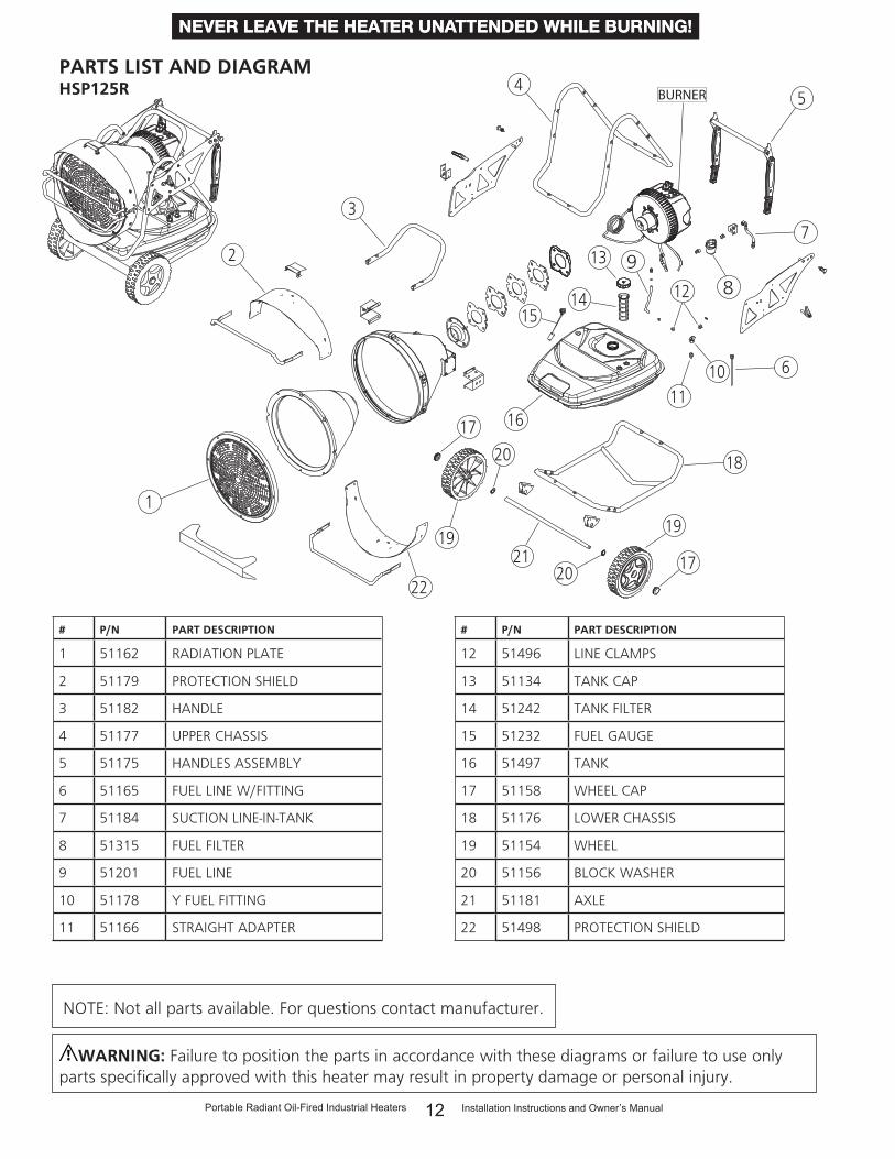
PARTS LIST AND DIAGRAMHSP125R
# P/N PART DESCRIPTION
1 51162 RADIATION PLATE
2 51179 PROTECTION SHIELD
3 51182 HANDLE
4 51177 UPPER CHASSIS
5 51175 HANDLES ASSEMBLY
6 51165 FUEL LINE W/FITTING
7 51184 SUCTION LINE-IN-TANK
8 51315 FUEL FILTER
9 51201 FUEL LINE
10 51178 Y FUEL FITTING
11 51166 STRAIGHT ADAPTER
# P/N PART DESCRIPTION
12 51496 LINE CLAMPS
13 51134 TANK CAP
14 51242 TANK FILTER
15 51232 FUEL GAUGE
16 51497 TANK
17 51158 WHEEL CAP
18 51176 LOWER CHASSIS
19 51154 WHEEL
20 51156 BLOCK WASHER
21 51181 AXLE
22 51498 PROTECTION SHIELD
WARNING: Failure to position the parts in accordance with these diagrams or failure to use only parts specifically approved with this heater may result in property damage or personal injury.
NOTE: Not all parts available. For questions contact manufacturer.

Installation Instructions and Owner’s ManualPortable Radiant Oil-Fired Industrial Heaters 13
NEVER LEAVE THE HEATER UNATTENDED WHILE BURNING!NEVER LEAVE THE HEATER UNATTENDED WHILE BURNING!NEVER LEAVE THE HEATER UNATTENDED WHILE BURNING!
PARTS LIST AND DIAGRAMHSP125R
# P/N PART DESCRIPTION
1 51295 NOZZLE,0.65GPH,80,S
2 51169 ELECTRODES
3 51499 POWER CORD
4 51500 BURNER FLANGE
5 51223 FUEL LINE-PUMP-NOZZLE
6 51187 FUEL PUMP
7 51207 PHOTOCELL
8 51222 PC-BOARD
9 51190 THERMOSTAT SOCKET
10 51191 THERMOSTAT PLUG
11 51193 THERMOSTAT CAP
12 51314 COVER,BURNER,HSP,150R
# P/N PART DESCRIPTION
13 51095 SWITCH
14 51216 DISPLAY BOARD
15 51231 ANTI,TILT,SWITCH
16 51235 VENTILATION MOTOR
17 51236 RESET SWITCH
18 51167 FUEL LINE-PUMP-TANK
19 51238 HIGH TENSION TRANSFORMER
20 51213 HIGH TENSION TRANS. WIRE
21 51050 SAFETY THERMOSTAT
22 51185 FUEL LINE-FILTER-PUMP
23 51244 FUSE
WARNING: Failure to position the parts in accordance with these diagrams or failure to use only parts specifically approved with this heater may result in property damage or personal injury.
NOTE: Not all parts available. For questions contact manufacturer.
1
2
6
7
5
4
3
8
9
15
17
18
1311
10
1412
16
2119
202223
BURNER

14 Installation Instructions and Owner’s ManualPortable Radiant Oil-Fired Industrial Heaters
NEVER LEAVE THE HEATER UNATTENDED WHILE BURNING!NEVER LEAVE THE HEATER UNATTENDED WHILE BURNING!NEVER LEAVE THE HEATER UNATTENDED WHILE BURNING!
PARTS LIST AND DIAGRAMHSP150R
BURNER
89
1
2
3
5
7
6
4
1011
18
12
13
15
16
20
20
17
19
22
21
19
17
14
# P/N PART DESCRIPTION
1 51162 RADIATION PLATE
2 51179 PROTECTION SHIELD
3 51182 HANDLE
4 51177 UPPER CHASSIS
5 51175 HANDLES ASSEMBLY
6 51165 SUCTION LINE W/FITTING
7 51184 FUEL LINE-TANK-FILTER
8 51315 FUEL FILTER
9 51201 FUEL LINE-VENT
10 51178 Y FUEL FITTING
11 51166 STRAIGHT ADAPTER
# P/N PART DESCRIPTION
12 51496 LINE CLAMPS
13 51134 TANK CAP
14 51242 TANK FILTER
15 51232 FUEL GAUGE
16 51497 TANK
17 51158 WHEEL CAP
18 51176 LOWER CHASSIS
19 51154 WHEEL
20 51156 BLOCK WASHER
21 51181 AXLE
22 51498 PROTECTION SHIELD
WARNING: Failure to position the parts in accordance with these diagrams or failure to use only parts specifically approved with this heater may result in property damage or personal injury.
NOTE: Not all parts available. For questions contact manufacturer.

Installation Instructions and Owner’s ManualPortable Radiant Oil-Fired Industrial Heaters 15
NEVER LEAVE THE HEATER UNATTENDED WHILE BURNING!NEVER LEAVE THE HEATER UNATTENDED WHILE BURNING!NEVER LEAVE THE HEATER UNATTENDED WHILE BURNING!
PARTS LIST AND DIAGRAMHSP150R
# P/N PART DESCRIPTION
1 51188 NOZZLE
2 51169 ELECTRODES
3 51499 POWER CORD
4 51500 BURNER FLANGE
5 51223 FUEL LINE-PUMP-NOZZLE
6 51187 FUEL PUMP
7 51207 PHOTOCELL
8 51222 PC-BOARD
9 51190 THERMOSTAT SOCKET
10 51191 THERMOSTAT PLUG
11 51193 THERMOSTAT CAP
12 51314 COVER,BURNER,HSP,150R
# P/N PART DESCRIPTION
13 51095 SWITCH
14 51216 DISPLAY BOARD
15 51231 ANTI,TILT,SWITCH
16 51235 VENTILATION MOTOR
17 51236 RESET SWITCH
18 51167 FUEL LINE-PUMP-TANK
19 51238 HIGH TENSION TRANSFORMER
20 51213 HIGH TENSION TRANS. WIRE
21 51050 SAFETY THERMOSTAT
22 51185 FUEL LINE-FILTER-PUMP
23 51244 FUSE
WARNING: Failure to position the parts in accordance with these diagrams or failure to use only parts specifically approved with this heater may result in property damage or personal injury.
NOTE: Not all parts available. For questions contact manufacturer.
1
2
6
7
5
4
3
8
9
15
17
18
1311
10
1412
16
2119
202223
BURNER

16 Installation Instructions and Owner’s ManualPortable Radiant Oil-Fired Industrial Heaters
NEVER LEAVE THE HEATER UNATTENDED WHILE BURNING!NEVER LEAVE THE HEATER UNATTENDED WHILE BURNING!NEVER LEAVE THE HEATER UNATTENDED WHILE BURNING!
L: Line
N: Neutral
MC: Burner motor
MF: Cooling motor
PM: Pump
IG: Ignitor
TR: Transformer
SV: Electrovalve
TA: Ambient Thermostat
IN: Switch
TS: Overheat Thermostat
AT: Anti-tilting switch
FO: Photocell
RE: Reset
WIRING DIAGRAM for HSP60R and HSP125R/150R

Installation Instructions and Owner’s ManualPortable Radiant Oil-Fired Industrial Heaters 17
NEVER LEAVE THE HEATER UNATTENDED WHILE BURNING!NEVER LEAVE THE HEATER UNATTENDED WHILE BURNING!NEVER LEAVE THE HEATER UNATTENDED WHILE BURNING!
NOTES:

18 Installation Instructions and Owner’s ManualPortable Radiant Oil-Fired Industrial Heaters
NEVER LEAVE THE HEATER UNATTENDED WHILE BURNING!NEVER LEAVE THE HEATER UNATTENDED WHILE BURNING!NEVER LEAVE THE HEATER UNATTENDED WHILE BURNING!
Enerco Group, Inc. reserves the right to make changes at any time, without notice or obligation, in colors, specifications, accessories, materials and models.
WARNING:USE ONLY MANUFACTURER’S REPLACEMENT PARTS. USE OF ANY OTHER PARTS COULD CAUSE INJURY OR DEATH. REPLACEMENT PARTS ARE ONLY AVAILABLE DIRECT FROM THE FACTORY AND MUST BE INSTALLED BY A QUALIFIED SERVICE AGENCY.
REPLACEMENT PARTS ORDERING INFORMATION:PURCHASING: Accessories may be purchased at any HEATSTAR by Enerco local dealer or direct from the factory FOR INFORMATION REGARDING SERVICEPlease call Toll-Free 866-447-2194WWW.HEATSTARBYENERCO.COMOur office hours are 8:00 AM – 5:00 PM, EST, Monday through Friday.Please include the model number, date of purchase, and description of problem in all communication.
LIMITED WARRANTYThe company warrants this product to be free from imperfections in material or workmanship, under normal and proper use in accordance with instructions of The Company, for a period of one year from the date of delivery to the buyer. The Company, at its option, will repair or replace products returned by the buyer to the factory, transportation prepaid within said one year period and found by the Company to have imperfections in material or workmanship.If a part is damaged or missing, call our Technical Support Department at 866-447-2194.Address any Warranty Claims to the Service Department, Enerco Group, Inc., 4560 W. 160TH ST., Cleveland, Ohio 44135. Include your name, address, telephone number, serial number off heater and include details concerning the claim. Also, supply us with the purchase date and the name and address of the dealer from whom you purchased our product.The foregoing is the full extent of the responsibility of the Company. There are no other warranties, express or implied. Specifically there is no warranty of fitness for a particular purpose and there is no warranty of merchantability. In no event shall the Company be liable for delay caused by imperfections, for consequential damages, or for any charges of the expense of any nature incurred without its written consent. The cost of repair or replacement shall be the exclusive remedy for any breach of warranty. There is no warranty against infringement of the like and no implied warranty arising from course of dealing or usage of trade. This warranty will not apply to any product which has been repaired or altered outside of the factory in any respect which in our judgment affects its condition or operation.Some states do not allow the exclusion or limitation of incidental or consequential damages, so the above limitation or exclusion may not apply to you. This Warranty gives you specific legal rights, and you may have other rights which vary from state to state.
ENERCO Technical Products, Inc., 4560 W. 160TH ST., CLEVELAND, OHIO 44135 • 866-447-2194HEATSTAR is a registered trademarks of ENERCO Technical Products, Inc.© 2017, ENERCO Technical Products. All rights reserved
OPERATING INSTRUCTIONS AND OWNER’S MANUAL
MODEL#HSP60R HSP125R
HSP150R
READ INSTRUCTIONS CAREFULLY: YOUR SAFETY IS IMPORTANT TO YOU AND TO OTHERS. Read and follow all instructions. Place instructions in a safe place for future reference. Do not allow anyone who has not read these instructions to assemble, light, adjust or operate the heater.