Portable Borehole Inspection System
23
970216_B 0815 EXPLORER Portable Borehole Inspection System (Models EX1200 / EX600 / WC1200) Cablehead Instruction Manual Aries Corporate Office: 550 Elizabeth Street, Waukesha, WI 53186 800-234-7205 / 262-896-7205 / Fax: 262-896-7099 Western Regional Office: 5748 East Shields Avenue, Suite 101, Fresno, CA 93727 800-671-0383 / 559-291-0383 / Fax: 559-291-0463 Southeast Regional Office: 561 Thornton Road, Suite D, Lithia Springs, GA 30122 800-327-4346 / 770-941-1144 / Fax: 770-941-1141 Canadian Regional Office: 95 Whitmore Road, Unit 1, Vaughan, Ontario L4L 6E2 877-730-7010 / 905-265-2279 / Fax: 905-265-2299 Aries Web Site: www.ariesindustries.com
Transcript of Portable Borehole Inspection System
970216_B 0815
EXPLORER
Portable Borehole Inspection System
(Models EX1200 / EX600 / WC1200)
Cablehead Instruction Manual
Aries Corporate Office: 550 Elizabeth Street, Waukesha, WI 53186
800-234-7205 / 262-896-7205 / Fax: 262-896-7099
Western Regional Office: 5748 East Shields Avenue, Suite 101, Fresno, CA 93727
800-671-0383 / 559-291-0383 / Fax: 559-291-0463
Southeast Regional Office: 561 Thornton Road, Suite D, Lithia Springs, GA 30122
800-327-4346 / 770-941-1144 / Fax: 770-941-1141
Canadian Regional Office: 95 Whitmore Road, Unit 1, Vaughan, Ontario L4L 6E2
877-730-7010 / 905-265-2279 / Fax: 905-265-2299
Aries Web Site: www.ariesindustries.com

970216_B 0815 550 Elizabeth St., Waukesha, WI 53186 1-800-234-7205 www.ariesindustries.com Page 2
This document contains proprietary and
confidential information of Aries Industries, Inc.
Copyright 2014 Aries Industries, Inc.
All rights reserved.
Disclaimer
The information contained in this document has been carefully checked and is believed to be
entirely reliable and consistent with the products described. However, no responsibility is
assumed for inaccuracies, nor does Aries Industries, Inc. assume any liability arising out of the
application and use of the equipment described. Aries Industries, Inc. reserves the right to make
changes to any product and product documentation in an effort to improve performance,
reliability, or design.
Warranty
Aries’ products are thoroughly inspected before shipment. In the event of any malfunction,
contact the nearest Aries office.
Aries will replace or repair defective manufactured parts, F.O.B. factory, for one year from the
date of shipment. See Aries’ full warranty statement for complete details.
Notice
No part of this document should be reprinted or reproduced without the prior written permission
of Aries Industries, Inc.
If you have any problems or questions regarding this document, please contact one of the Aries’ offices listed on the front cover.

970216_B 0815 550 Elizabeth St., Waukesha, WI 53186 1-800-234-7205 www.ariesindustries.com Page 3
Recommended tools:
Sharp scissors
10”-12” Adjustable wrench
X-Acto (utility) knife
Vise (not shown)
Wire cutters
Small screwdrivers (Flat and Phillips)
5/8” deep socket and wrench
13/16” open ended wrench

970216_B 0815 550 Elizabeth St., Waukesha, WI 53186 1-800-234-7205 www.ariesindustries.com Page 4
Feed the cable through the black coiled strain relief and stainless steel housing.
Next, install the strain relief body onto the cable.

970216_B 0815 550 Elizabeth St., Waukesha, WI 53186 1-800-234-7205 www.ariesindustries.com Page 5
Measure back about 6 inches and mark the cable. Cut the outer red jacket of the cable.
DO NOT CUT INTO THE KEVLAR® BRAID. Tip: If you score the jacket and bend it
backwards it will begin to separate without having to cut too deeply.
Carefully cut the outer jacket. Again, try not to cut the inner braided material. If you can cut
through approximately half of the jacket without going through you should attempt the step
below.

970216_B 0815 550 Elizabeth St., Waukesha, WI 53186 1-800-234-7205 www.ariesindustries.com Page 6
The red outer jacket needs to be removed from the Kevlar® braid. If you cut the end of the cable
at a 45-degree angle and separate the jacket at its highest point, it will allow for an easier method
of peeling the jacket away.
970216_B 0815 550 Elizabeth St., Waukesha, WI 53186 1-800-234-7205 www.ariesindustries.com Page 7
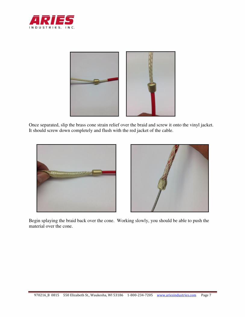
Once separated, slip the brass cone strain relief over the braid and screw it onto the vinyl jacket.
It should screw down completely and flush with the red jacket of the cable.
Begin splaying the braid back over the cone. Working slowly, you should be able to push the
material over the cone.

970216_B 0815 550 Elizabeth St., Waukesha, WI 53186 1-800-234-7205 www.ariesindustries.com Page 8
Insert the assembly as shown above and secure in place with the strain relief. Using a crisscross
pattern, tighten the four screws firmly.

970216_B 0815 550 Elizabeth St., Waukesha, WI 53186 1-800-234-7205 www.ariesindustries.com Page 9
Trim the braided Kevlar® as shown above.

970216_B 0815 550 Elizabeth St., Waukesha, WI 53186 1-800-234-7205 www.ariesindustries.com Page 10
Lightly score the outside clear plastic wrap. Peeling it away from the end of the cable will make
the job a little easier (counterclockwise).
970216_B 0815 550 Elizabeth St., Waukesha, WI 53186 1-800-234-7205 www.ariesindustries.com Page 11
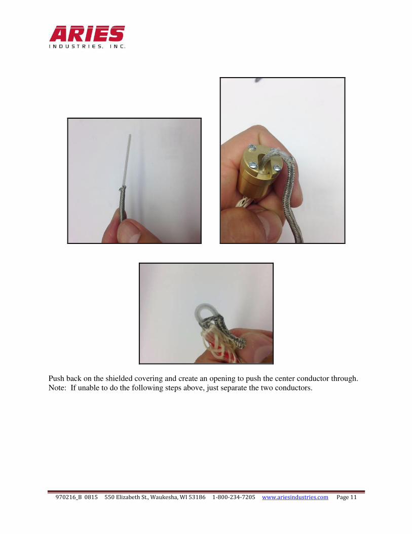
Push back on the shielded covering and create an opening to push the center conductor through.
Note: If unable to do the following steps above, just separate the two conductors.

970216_B 0815 550 Elizabeth St., Waukesha, WI 53186 1-800-234-7205 www.ariesindustries.com Page 12
Cut the wires back about 2 inches. Strip the center conductor about ¼-inch.

970216_B 0815 550 Elizabeth St., Waukesha, WI 53186 1-800-234-7205 www.ariesindustries.com Page 13
Attach the wires to the terminals.
Insert the strain relief assembly and firmly tug the cable to seat it in place.
*NOTE: The wrapping technique is not absolutely necessary, but ensures the greatest amount of
strain relief for the cable.

970216_B 0815 550 Elizabeth St., Waukesha, WI 53186 1-800-234-7205 www.ariesindustries.com Page 14
CONNECTOR ASSEMBLY
Locate the wires labeled #1, #2, and #10. Wires #1 and #2 are Ground connections. Wire #10 is
POWER to the camera. Cut the remaining seven wires to approximately ½ inches long.
Feed the wires through the connector housing. Ensure the o-ring is clean and clear of debris and
is not cut or damaged. Cut the three remaining wires #1, #2, and #10 to about 2 inches in length.

970216_B 0815 550 Elizabeth St., Waukesha, WI 53186 1-800-234-7205 www.ariesindustries.com Page 15
Inspect the o-ring for any damage prior to putting it in place.
Screw the two pieces together. Use a vise and a 13/16” open ended wrench to firmly tighten the connector in place.

970216_B 0815 550 Elizabeth St., Waukesha, WI 53186 1-800-234-7205 www.ariesindustries.com Page 16
Use a vise to screw the cylindrical nut onto the exposed threads. Double the wires over and slide
the 5/8-inch socket over the retaining nut. Tighten the nut in place.

970216_B 0815 550 Elizabeth St., Waukesha, WI 53186 1-800-234-7205 www.ariesindustries.com Page 17
Strip back and connect wires #1 and #2 together. Strip back wire #10. Connect the wires as
shown. Wires #1 and #2 connect to the shield and wire #10 connects to the center conductor.

970216_B 0815 550 Elizabeth St., Waukesha, WI 53186 1-800-234-7205 www.ariesindustries.com Page 18
Insert wires #1 and #2 to mate up with the shield of the cable. Insert the wire marked #10 to
connect to the center conductor.
Turn the collar counterclockwise 5-½ turns before screwing the two pieces together. Use a vise
and a large adjustable wrench to tighten both pieces together.

970216_B 0815 550 Elizabeth St., Waukesha, WI 53186 1-800-234-7205 www.ariesindustries.com Page 19
Screw the end connector onto the top half of the housing with an adjustable wrench.

970216_B 0815 550 Elizabeth St., Waukesha, WI 53186 1-800-234-7205 www.ariesindustries.com Page 20
Note: Tug firmly on the red cable to ensure there is no slack inside the cablehead before
tightening the final strain relief nut.

970216_B 0815 550 Elizabeth St., Waukesha, WI 53186 1-800-234-7205 www.ariesindustries.com Page 21
Install the strain relief and tighten the flexible cable relief in place.

970216_B 0815 550 Elizabeth St., Waukesha, WI 53186 1-800-234-7205 www.ariesindustries.com Page 22
Your cablehead is now complete.

970216_B 0815 550 Elizabeth St., Waukesha, WI 53186 1-800-234-7205 www.ariesindustries.com Page 23