Port Status and Basic...
38
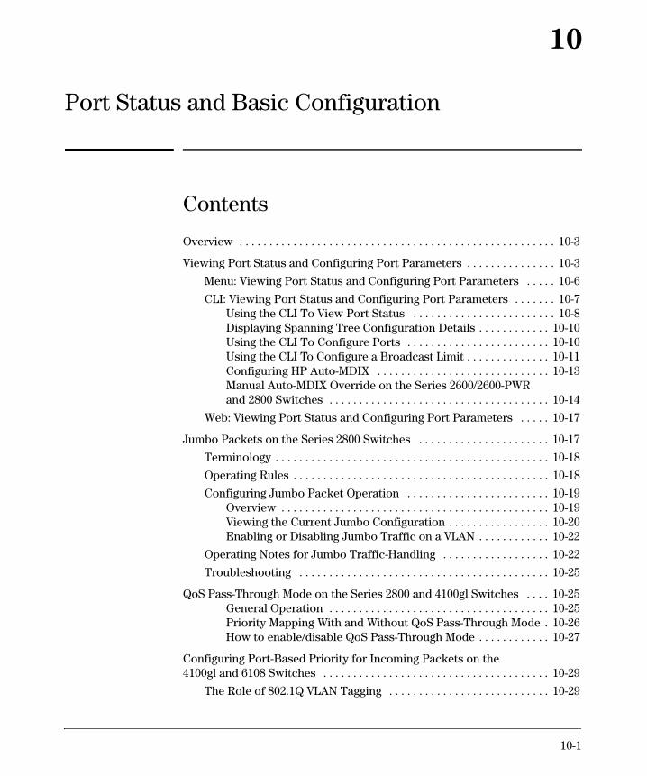
10-1 10 Port Status and Basic Configuration Contents Overview . . . . . . . . . . . . . . . . . . . . . . . . . . . . . . . . . . . . . . . . . . . . . . . . . . . . . 10-3 Viewing Port Status and Configuring Port Parameters . . . . . . . . . . . . . . . 10-3 Menu: Viewing Port Status and Configuring Port Parameters . . . . . 10-6 CLI: Viewing Port Status and Configuring Port Parameters . . . . . . . 10-7 Using the CLI To View Port Status . . . . . . . . . . . . . . . . . . . . . . . . 10-8 Displaying Spanning Tree Configuration Details . . . . . . . . . . . . 10-10 Using the CLI To Configure Ports . . . . . . . . . . . . . . . . . . . . . . . . 10-10 Using the CLI To Configure a Broadcast Limit . . . . . . . . . . . . . . 10-11 Configuring HP Auto-MDIX . . . . . . . . . . . . . . . . . . . . . . . . . . . . . 10-13 Manual Auto-MDIX Override on the Series 2600/2600-PWR and 2800 Switches . . . . . . . . . . . . . . . . . . . . . . . . . . . . . . . . . . . . . 10-14 Web: Viewing Port Status and Configuring Port Parameters . . . . . 10-17 Jumbo Packets on the Series 2800 Switches . . . . . . . . . . . . . . . . . . . . . . 10-17 Terminology . . . . . . . . . . . . . . . . . . . . . . . . . . . . . . . . . . . . . . . . . . . . . . 10-18 Operating Rules . . . . . . . . . . . . . . . . . . . . . . . . . . . . . . . . . . . . . . . . . . . 10-18 Configuring Jumbo Packet Operation . . . . . . . . . . . . . . . . . . . . . . . . 10-19 Overview . . . . . . . . . . . . . . . . . . . . . . . . . . . . . . . . . . . . . . . . . . . . . 10-19 Viewing the Current Jumbo Configuration . . . . . . . . . . . . . . . . . 10-20 Enabling or Disabling Jumbo Traffic on a VLAN . . . . . . . . . . . . 10-22 Operating Notes for Jumbo Traffic-Handling . . . . . . . . . . . . . . . . . . 10-22 Troubleshooting . . . . . . . . . . . . . . . . . . . . . . . . . . . . . . . . . . . . . . . . . . 10-25 QoS Pass-Through Mode on the Series 2800 and 4100gl Switches . . . . 10-25 General Operation . . . . . . . . . . . . . . . . . . . . . . . . . . . . . . . . . . . . . 10-25 Priority Mapping With and Without QoS Pass-Through Mode . 10-26 How to enable/disable QoS Pass-Through Mode . . . . . . . . . . . . 10-27 Configuring Port-Based Priority for Incoming Packets on the 4100gl and 6108 Switches . . . . . . . . . . . . . . . . . . . . . . . . . . . . . . . . . . . . . . 10-29 The Role of 802.1Q VLAN Tagging . . . . . . . . . . . . . . . . . . . . . . . . . . . 10-29
Transcript of Port Status and Basic...
10
Port Status and Basic Configuration
Contents
Overview . . . . . . . . . . . . . . . . . . . . . . . . . . . . . . . . . . . . . . . . . . . . . . . . . . . . . 10-3
Viewing Port Status and Configuring Port Parameters . . . . . . . . . . . . . . . 10-3
Menu: Viewing Port Status and Configuring Port Parameters . . . . . 10-6
CLI: Viewing Port Status and Configuring Port Parameters . . . . . . . 10-7Using the CLI To View Port Status . . . . . . . . . . . . . . . . . . . . . . . . 10-8Displaying Spanning Tree Configuration Details . . . . . . . . . . . . 10-10Using the CLI To Configure Ports . . . . . . . . . . . . . . . . . . . . . . . . 10-10Using the CLI To Configure a Broadcast Limit . . . . . . . . . . . . . . 10-11Configuring HP Auto-MDIX . . . . . . . . . . . . . . . . . . . . . . . . . . . . . 10-13Manual Auto-MDIX Override on the Series 2600/2600-PWR and 2800 Switches . . . . . . . . . . . . . . . . . . . . . . . . . . . . . . . . . . . . . 10-14
Web: Viewing Port Status and Configuring Port Parameters . . . . . 10-17
Jumbo Packets on the Series 2800 Switches . . . . . . . . . . . . . . . . . . . . . . 10-17
Terminology . . . . . . . . . . . . . . . . . . . . . . . . . . . . . . . . . . . . . . . . . . . . . . 10-18
Operating Rules . . . . . . . . . . . . . . . . . . . . . . . . . . . . . . . . . . . . . . . . . . . 10-18
Configuring Jumbo Packet Operation . . . . . . . . . . . . . . . . . . . . . . . . 10-19Overview . . . . . . . . . . . . . . . . . . . . . . . . . . . . . . . . . . . . . . . . . . . . . 10-19Viewing the Current Jumbo Configuration . . . . . . . . . . . . . . . . . 10-20Enabling or Disabling Jumbo Traffic on a VLAN . . . . . . . . . . . . 10-22
Operating Notes for Jumbo Traffic-Handling . . . . . . . . . . . . . . . . . . 10-22
Troubleshooting . . . . . . . . . . . . . . . . . . . . . . . . . . . . . . . . . . . . . . . . . . 10-25
QoS Pass-Through Mode on the Series 2800 and 4100gl Switches . . . . 10-25General Operation . . . . . . . . . . . . . . . . . . . . . . . . . . . . . . . . . . . . . 10-25Priority Mapping With and Without QoS Pass-Through Mode . 10-26How to enable/disable QoS Pass-Through Mode . . . . . . . . . . . . 10-27
Configuring Port-Based Priority for Incoming Packets on the 4100gl and 6108 Switches . . . . . . . . . . . . . . . . . . . . . . . . . . . . . . . . . . . . . . 10-29
The Role of 802.1Q VLAN Tagging . . . . . . . . . . . . . . . . . . . . . . . . . . . 10-29
10-1
Port Status and Basic Configuration Contents
Outbound Port Queues and Packet Priority Settings . . . . . . . . . . . . 10-30
Operating Rules for Port-Based Priority . . . . . . . . . . . . . . . . . . . . . . 10-31
Configuring and Viewing Port-Based Priority . . . . . . . . . . . . . . . . . . 10-32
Messages Related to Prioritization . . . . . . . . . . . . . . . . . . . . . . . . . . . 10-33
Troubleshooting Prioritization . . . . . . . . . . . . . . . . . . . . . . . . . . . . . . 10-33
Using Friendly (Optional) Port Names . . . . . . . . . . . . . . . . . . . . . . . . . . . 10-34
Configuring and Operating Rules for Friendly Port Names . . . . . . . 10-34
Configuring Friendly Port Names . . . . . . . . . . . . . . . . . . . . . . . . . . . . 10-35
Displaying Friendly Port Names with Other Port Data . . . . . . . . . . 10-37
10-2
Port Status and Basic ConfigurationOverview
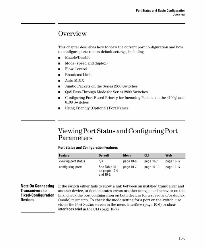
Overview
This chapter describes how to view the current port configuration and how to configure ports to non-default settings, including
■ Enable/Disable
■ Mode (speed and duplex)
■ Flow Control
■ Broadcast Limit
■ Auto-MDIX
■ Jumbo Packets on the Series 2800 Switches
■ QoS Pass-Through Mode for Series 2800 Switches
■ Configuring Port-Based Priority for Incoming Packets on the 4100gl and 6108 Switches
■ Using Friendly (Optional) Port Names
Viewing Port Status and Configuring Port ParametersPort Status and Configuration Features
Note On Connecting Transceivers to Fixed-Configuration Devices
If the switch either fails to show a link between an installed transceiver and another device, or demonstrates errors or other unexpected behavior on the link, check the port configuration on both devices for a speed and/or duplex (mode) mismatch. To check the mode setting for a port on the switch, use either the Port Status screen in the menu interface (page 10-6) or show interfaces brief in the CLI (page 10-7).
Feature Default Menu CLI Web
viewing port status n/a page 10-6 page 10-7 page 10-17
configuring ports See Table 10-1 on pages 10-4 and 10-5.
page 10-7 page 10-10 page 10-17
10-3
Port Status and Basic Configuration Viewing Port Status and Configuring Port Parameters
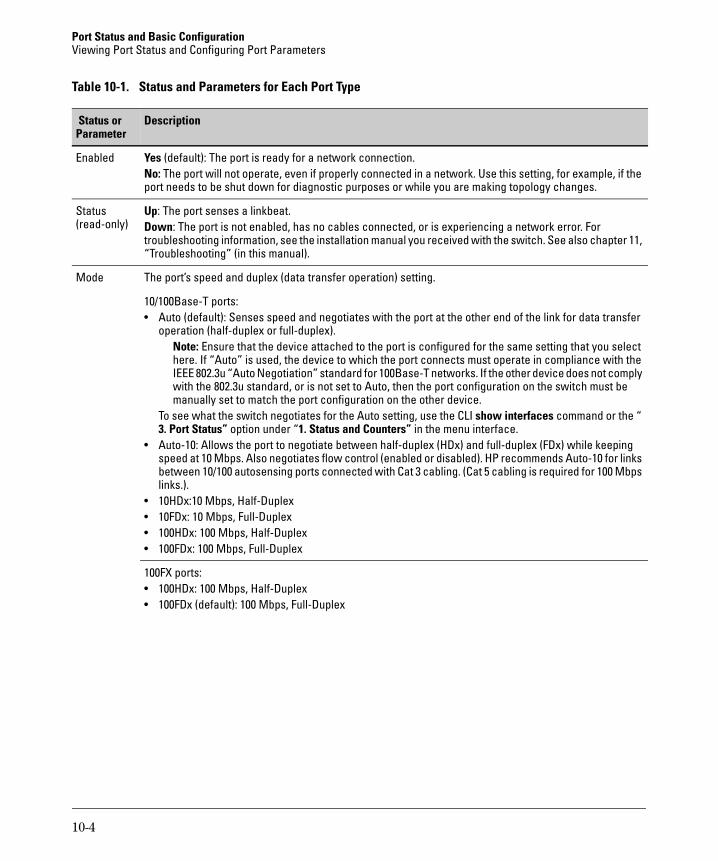
Table 10-1. Status and Parameters for Each Port Type
Status or Parameter
Description
Enabled Yes (default): The port is ready for a network connection.No: The port will not operate, even if properly connected in a network. Use this setting, for example, if the port needs to be shut down for diagnostic purposes or while you are making topology changes.
Status(read-only)
Up: The port senses a linkbeat.Down: The port is not enabled, has no cables connected, or is experiencing a network error. For troubleshooting information, see the installation manual you received with the switch. See also chapter 11, “Troubleshooting” (in this manual).
Mode The port’s speed and duplex (data transfer operation) setting.
10/100Base-T ports:• Auto (default): Senses speed and negotiates with the port at the other end of the link for data transfer
operation (half-duplex or full-duplex).Note: Ensure that the device attached to the port is configured for the same setting that you select here. If “Auto” is used, the device to which the port connects must operate in compliance with the IEEE 802.3u “Auto Negotiation” standard for 100Base-T networks. If the other device does not comply with the 802.3u standard, or is not set to Auto, then the port configuration on the switch must be manually set to match the port configuration on the other device.
To see what the switch negotiates for the Auto setting, use the CLI show interfaces command or the “ 3. Port Status” option under “1. Status and Counters” in the menu interface.
• Auto-10: Allows the port to negotiate between half-duplex (HDx) and full-duplex (FDx) while keeping speed at 10 Mbps. Also negotiates flow control (enabled or disabled). HP recommends Auto-10 for links between 10/100 autosensing ports connected with Cat 3 cabling. (Cat 5 cabling is required for 100 Mbps links.).
• 10HDx:10 Mbps, Half-Duplex• 10FDx: 10 Mbps, Full-Duplex• 100HDx: 100 Mbps, Half-Duplex• 100FDx: 100 Mbps, Full-Duplex
100FX ports:• 100HDx: 100 Mbps, Half-Duplex• 100FDx (default): 100 Mbps, Full-Duplex
10-4
Port Status and Basic ConfigurationViewing Port Status and Configuring Port Parameters
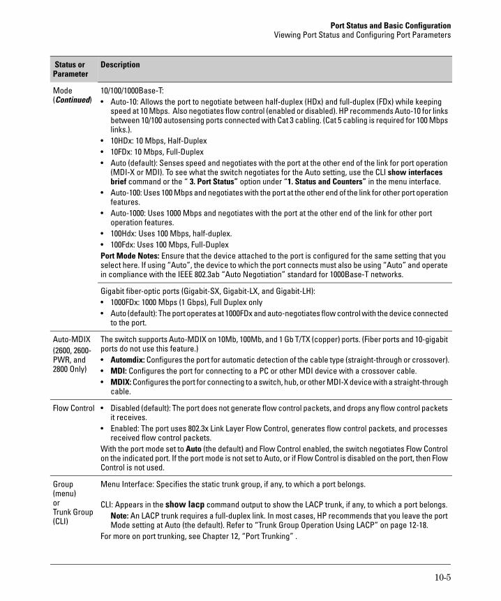
Mode(Continued)
10/100/1000Base-T: • Auto-10: Allows the port to negotiate between half-duplex (HDx) and full-duplex (FDx) while keeping
speed at 10 Mbps. Also negotiates flow control (enabled or disabled). HP recommends Auto-10 for links between 10/100 autosensing ports connected with Cat 3 cabling. (Cat 5 cabling is required for 100 Mbps links.).
• 10HDx: 10 Mbps, Half-Duplex• 10FDx: 10 Mbps, Full-Duplex• Auto (default): Senses speed and negotiates with the port at the other end of the link for port operation
(MDI-X or MDI). To see what the switch negotiates for the Auto setting, use the CLI show interfaces brief command or the “ 3. Port Status” option under “1. Status and Counters” in the menu interface.
• Auto-100: Uses 100 Mbps and negotiates with the port at the other end of the link for other port operation features.
• Auto-1000: Uses 1000 Mbps and negotiates with the port at the other end of the link for other port operation features.
• 100Hdx: Uses 100 Mbps, half-duplex.• 100Fdx: Uses 100 Mbps, Full-DuplexPort Mode Notes: Ensure that the device attached to the port is configured for the same setting that you select here. If using “Auto”, the device to which the port connects must also be using “Auto” and operate in compliance with the IEEE 802.3ab “Auto Negotiation” standard for 1000Base-T networks.
Gigabit fiber-optic ports (Gigabit-SX, Gigabit-LX, and Gigabit-LH):• 1000FDx: 1000 Mbps (1 Gbps), Full Duplex only• Auto (default): The port operates at 1000FDx and auto-negotiates flow control with the device connected
to the port.
Auto-MDIX(2600, 2600-PWR, and 2800 Only)
The switch supports Auto-MDIX on 10Mb, 100Mb, and 1 Gb T/TX (copper) ports. (Fiber ports and 10-gigabit ports do not use this feature.)• Automdix: Configures the port for automatic detection of the cable type (straight-through or crossover).• MDI: Configures the port for connecting to a PC or other MDI device with a crossover cable.• MDIX: Configures the port for connecting to a switch, hub, or other MDI-X device with a straight-through
cable.
Flow Control • Disabled (default): The port does not generate flow control packets, and drops any flow control packets it receives.
• Enabled: The port uses 802.3x Link Layer Flow Control, generates flow control packets, and processes received flow control packets.
With the port mode set to Auto (the default) and Flow Control enabled, the switch negotiates Flow Control on the indicated port. If the port mode is not set to Auto, or if Flow Control is disabled on the port, then Flow Control is not used.
Group (menu) orTrunk Group (CLI)
Menu Interface: Specifies the static trunk group, if any, to which a port belongs.
CLI: Appears in the show lacp command output to show the LACP trunk, if any, to which a port belongs.Note: An LACP trunk requires a full-duplex link. In most cases, HP recommends that you leave the port Mode setting at Auto (the default). Refer to “Trunk Group Operation Using LACP” on page 12-18.
For more on port trunking, see Chapter 12, “Port Trunking” .
Status or Parameter
Description
10-5
Port Status and Basic Configuration Viewing Port Status and Configuring Port Parameters
Menu: Viewing Port Status and Configuring Port Parameters
From the menu interface, you can configure and view all port parameter settings and view all port status indicators.
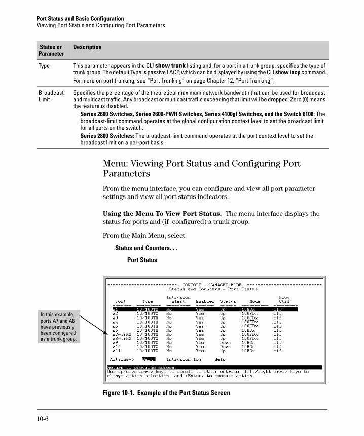
Using the Menu To View Port Status. The menu interface displays the status for ports and (if configured) a trunk group.
From the Main Menu, select:
Status and Counters. . .
Port Status
Figure 10-1. Example of the Port Status Screen
Type This parameter appears in the CLI show trunk listing and, for a port in a trunk group, specifies the type of trunk group. The default Type is passive LACP, which can be displayed by using the CLI show lacp command.For more on port trunking, see “Port Trunking” on page Chapter 12, “Port Trunking” .
Broadcast Limit
Specifies the percentage of the theoretical maximum network bandwidth that can be used for broadcast and multicast traffic. Any broadcast or multicast traffic exceeding that limit will be dropped. Zero (0) means the feature is disabled.
Series 2600 Switches, Series 2600-PWR Switches, Series 4100gl Switches, and the Switch 6108: The broadcast-limit command operates at the global configuration context level to set the broadcast limit for all ports on the switch.Series 2800 Switches: The broadcast-limit command operates at the port context level to set the broadcast limit on a per-port basis.
Status or Parameter
Description
In this example, ports A7 and A8 have previously been configured as a trunk group.
10-6
Port Status and Basic ConfigurationViewing Port Status and Configuring Port Parameters
Using the Menu To Configure Ports.
N o t e The menu interface uses the same screen for configuring both individual ports and port trunk groups. For information on port trunk groups, see Chapter 12, “Port Trunking” .
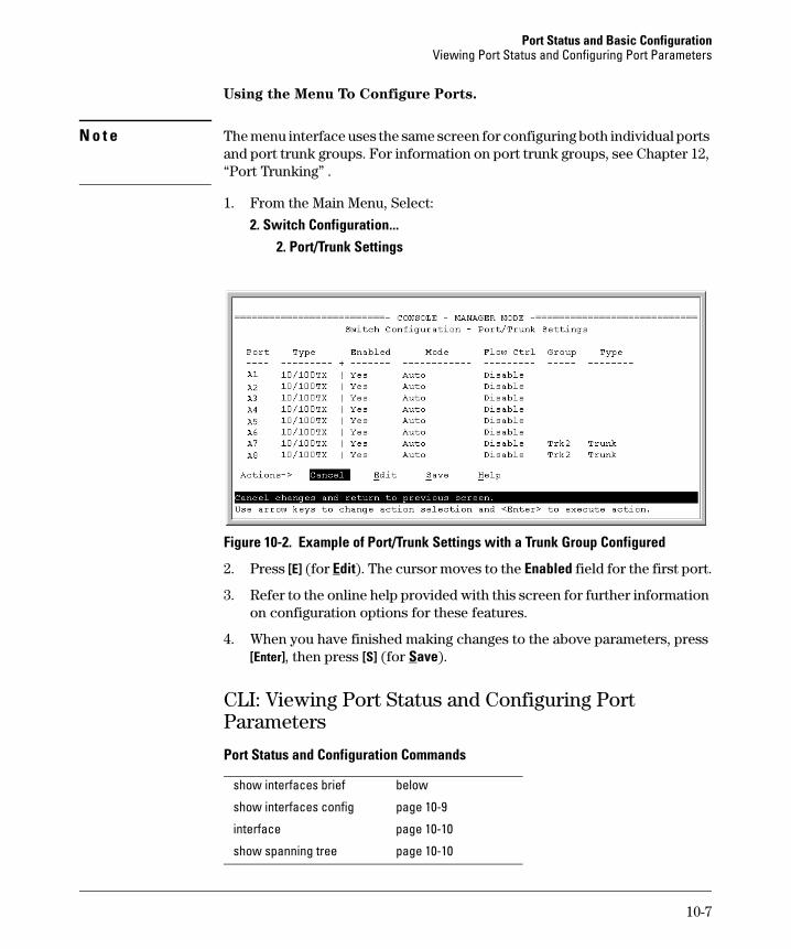
1. From the Main Menu, Select:
2. Switch Configuration...2. Port/Trunk Settings
Figure 10-2. Example of Port/Trunk Settings with a Trunk Group Configured
2. Press [E] (for Edit). The cursor moves to the Enabled field for the first port.
3. Refer to the online help provided with this screen for further information on configuration options for these features.
4. When you have finished making changes to the above parameters, press [Enter], then press [S] (for Save).
CLI: Viewing Port Status and Configuring Port Parameters
Port Status and Configuration Commands
show interfaces brief below
show interfaces config page 10-9
interface page 10-10
show spanning tree page 10-10
10-7
Port Status and Basic Configuration Viewing Port Status and Configuring Port Parameters
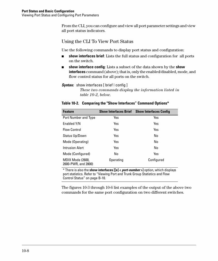
From the CLI, you can configure and view all port parameter settings and view all port status indicators.
Using the CLI To View Port Status
Use the following commands to display port status and configuration:
■ show interfaces brief: Lists the full status and configuration for all ports on the switch.
■ show interface config: Lists a subset of the data shown by the show interfaces command (above); that is, only the enabled/disabled, mode, and flow control status for all ports on the switch.
Syntax: show interfaces [ brief | config ]These two commands display the information listed in
table 10-2, below.
Table 10-2. Comparing the "Show Interfaces” Command Options*
The figures 10-3 through 10-6 list examples of the output of the above two commands for the same port configuration on two different switches.
Feature Show Interfaces Brief Show Interfaces Config
Port Number and Type Yes Yes
Enabled Y/N Yes Yes
Flow Control Yes Yes
Status Up/Down Yes No
Mode (Operating) Yes No
Intrusion Alert Yes No
Mode (Configured) No Yes
MDIX Mode (2600, 2600-PWR, and 2800)
Operating Configured
* There is also the show interfaces [[e] < port-number >] option, which displays port statistics. Refer to “Viewing Port and Trunk Group Statistics and Flow Control Status” on page B-10.
10-8
Port Status and Basic ConfigurationViewing Port Status and Configuring Port Parameters
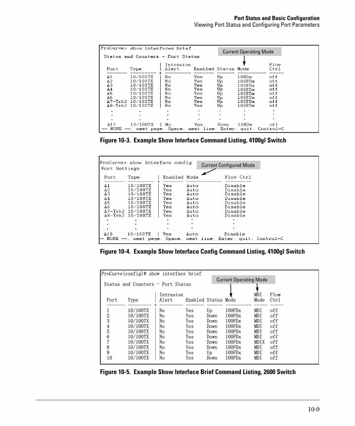
Figure 10-3. Example Show Interface Command Listing, 4100gl Switch
Figure 10-4. Example Show Interface Config Command Listing, 4100gl Switch
Figure 10-5. Example Show Interface Brief Command Listing, 2600 Switch
Current Operating Mode
Current Configured Mode
ProCurve(config)# show interface brief
Status and Counters - Port Status
| Intrusion MDI Flow Port Type | Alert Enabled Status Mode Mode Ctrl ------- --------- + --------- ------- ------ ---------- ----- ----- 1 10/100TX | No Yes Up 100FDx MDI off 2 10/100TX | No Yes Down 100FDx MDI off 3 10/100TX | No Yes Down 100FDx MDI off 4 10/100TX | No Yes Down 100FDx MDI off 5 10/100TX | No Yes Down 100FDx MDI off 6 10/100TX | No Yes Down 100FDx MDI off 7 10/100TX | No Yes Down 100FDx MDIX off 8 10/100TX | No Yes Down 100FDx MDI off 9 10/100TX | No Yes Up 100FDx MDI off 10 10/100TX | No Yes Down 100FDx MDI off
Current Operating Mode
10-9
Port Status and Basic Configuration Viewing Port Status and Configuring Port Parameters
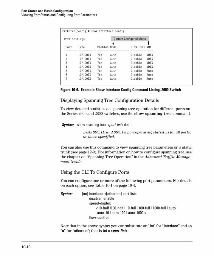
Figure 10-6. Example Show Interface Config Command Listing, 2600 Switch
Displaying Spanning Tree Configuration Details
To view detailed statistics on spanning tree operation for different ports on the Series 2600 and 2800 switches, use the show spanning-tree command.
You can also use this command to view spanning tree parameters on a static trunk (see page 12-9). For information on how to configure spanning tree, see the chapter on “Spanning-Tree Operation” in the Advanced Traffic Manage-
ment Guide.
Using the CLI To Configure Ports
You can configure one or more of the following port parameters. For details on each option, see Table 10-1 on page 10-4.
Syntax: [no] interface <[ethernet] port-list> disable | enablespeed-duplex <10-half |100-half | 10-full | 100-full | 1000-full | auto |
auto-10 | auto-100 | auto-1000 >flow-control
Note that in the above syntax you can substitute an “int” for “interface” and an “e” for “ethernet”; that is int e <port-list>.
Syntax: show spanning-tree <port-list> detail
Lists 802.1D and 802.1w port operating statistics for all ports,
or those specified.
ProCurve(config)# show interface config
Port Settings
Port Type | Enabled Mode Flow Ctrl MDI
------- --------- + ------- ------------ --------- ----
1 10/100TX | Yes Auto Disable MDIX
2 10/100TX | Yes Auto Disable MDIX
3 10/100TX | Yes Auto Disable MDIX
4 10/100TX | Yes Auto Disable MDIX
5 10/100TX | Yes Auto Disable Auto
6 10/100TX | Yes Auto Disable Auto
7 10/100TX | Yes Auto Disable Auto
Current Configured Mode
10-10
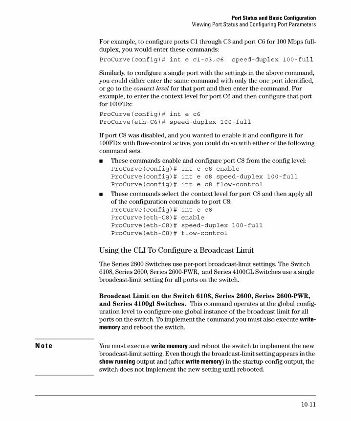
Port Status and Basic ConfigurationViewing Port Status and Configuring Port Parameters
For example, to configure ports C1 through C3 and port C6 for 100 Mbps full-duplex, you would enter these commands:
ProCurve(config)# int e c1-c3,c6 speed-duplex 100-full
Similarly, to configure a single port with the settings in the above command, you could either enter the same command with only the one port identified, or go to the context level for that port and then enter the command. For example, to enter the context level for port C6 and then configure that port for 100FDx:
ProCurve(config)# int e c6ProCurve(eth-C6)# speed-duplex 100-full
If port C8 was disabled, and you wanted to enable it and configure it for 100FDx with flow-control active, you could do so with either of the following command sets.
■ These commands enable and configure port C8 from the config level:ProCurve(config)# int e c8 enable ProCurve(config)# int e c8 speed-duplex 100-fullProCurve(config)# int e c8 flow-control
■ These commands select the context level for port C8 and then apply all of the configuration commands to port C8:ProCurve(config)# int e c8ProCurve(eth-C8)# enable ProCurve(eth-C8)# speed-duplex 100-full ProCurve(eth-C8)# flow-control
Using the CLI To Configure a Broadcast Limit
The Series 2800 Switches use per-port broadcast-limit settings. The Switch 6108, Series 2600, Series 2600-PWR, and Series 4100GL Switches use a single broadcast-limit setting for all ports on the switch.
Broadcast Limit on the Switch 6108, Series 2600, Series 2600-PWR,
and Series 4100gl Switches. This command operates at the global config-uration level to configure one global instance of the broadcast limit for all ports on the switch. To implement the command you must also execute write-memory and reboot the switch.
N o t e You must execute write memory and reboot the switch to implement the new broadcast-limit setting. Even though the broadcast-limit setting appears in the show running output and (after write memory) in the startup-config output, the switch does not implement the new setting until rebooted.
10-11
Port Status and Basic Configuration Viewing Port Status and Configuring Port Parameters
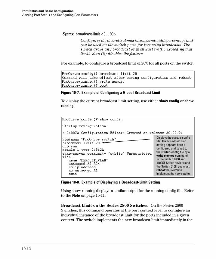
For example, to configure a broadcast limit of 20% for all ports on the switch:
Figure 10-7. Example of Configuring a Global Broadcast Limit
To display the current broadcast limit setting, use either show config or show running:
Figure 10-8. Example of Displaying a Broadcast-Limit Setting
Using show running displays a similar output for the running-config file. Refer to the Note on page 10-11.
Broadcast Limit on the Series 2800 Switches. On the Series 2800 Switches, this command operates at the port context level to configure an individual instance of the broadcast limit for the ports included in a given context. The switch implements the new broadcast limit immediately in the
Syntax: broadcast-limit < 0 . . 99 >
Configures the theoretical maximum bandwidth percentage that
can be used on the switch ports for incoming broadcasts. The
switch drops any broadcast or multicast traffic exceeding that
limit. Zero (0) disables the feature.
Displays the startup-config file. The broadcast limit setting appears here if configured and saved to the startup-config file by a write memory command. In the Switch 2600 and 4100GL Series devices and the Switch 6108, you must reboot the switch to implement the new setting.
10-12
Port Status and Basic ConfigurationViewing Port Status and Configuring Port Parameters
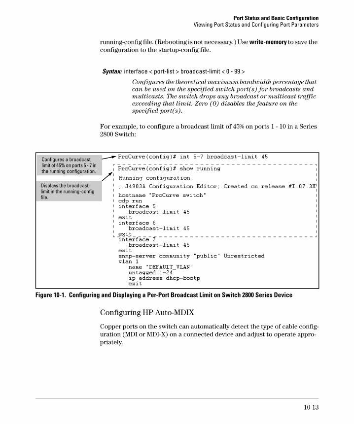
running-config file. (Rebooting is not necessary.) Use write-memory to save the configuration to the startup-config file.
For example, to configure a broadcast limit of 45% on ports 1 - 10 in a Series 2800 Switch:
Figure 10-1. Configuring and Displaying a Per-Port Broadcast Limit on Switch 2800 Series Device
Configuring HP Auto-MDIX
Copper ports on the switch can automatically detect the type of cable config-uration (MDI or MDI-X) on a connected device and adjust to operate appro-priately.
Syntax: interface < port-list > broadcast-limit < 0 - 99 >
Configures the theoretical maximum bandwidth percentage that
can be used on the specified switch port(s) for broadcasts and
multicasts. The switch drops any broadcast or multicast traffic
exceeding that limit. Zero (0) disables the feature on the
specified port(s).
Configures a broadcast limit of 45% on ports 5 - 7 in the running configuration.
Displays the broadcast-limit in the running-config file.
10-13
Port Status and Basic Configuration Viewing Port Status and Configuring Port Parameters
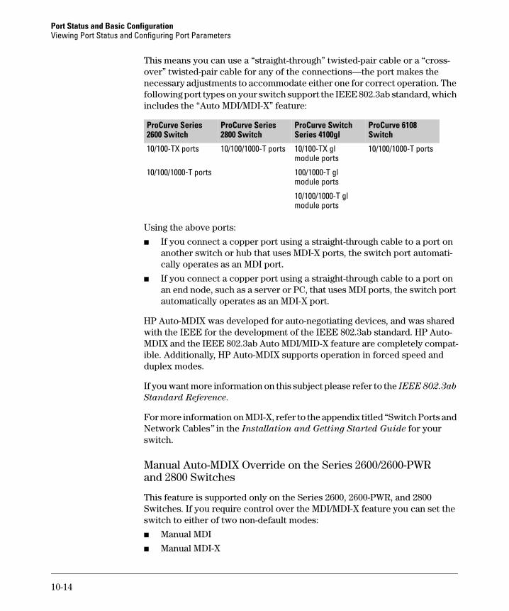
This means you can use a “straight-through” twisted-pair cable or a “cross-over” twisted-pair cable for any of the connections—the port makes the necessary adjustments to accommodate either one for correct operation. The following port types on your switch support the IEEE 802.3ab standard, which includes the “Auto MDI/MDI-X” feature:
Using the above ports:
■ If you connect a copper port using a straight-through cable to a port on another switch or hub that uses MDI-X ports, the switch port automati-cally operates as an MDI port.
■ If you connect a copper port using a straight-through cable to a port on an end node, such as a server or PC, that uses MDI ports, the switch port automatically operates as an MDI-X port.
HP Auto-MDIX was developed for auto-negotiating devices, and was shared with the IEEE for the development of the IEEE 802.3ab standard. HP Auto-MDIX and the IEEE 802.3ab Auto MDI/MID-X feature are completely compat-ible. Additionally, HP Auto-MDIX supports operation in forced speed and duplex modes.
If you want more information on this subject please refer to the IEEE 802.3ab
Standard Reference.
For more information on MDI-X, refer to the appendix titled “Switch Ports and Network Cables” in the Installation and Getting Started Guide for your switch.
Manual Auto-MDIX Override on the Series 2600/2600-PWR and 2800 Switches
This feature is supported only on the Series 2600, 2600-PWR, and 2800 Switches. If you require control over the MDI/MDI-X feature you can set the switch to either of two non-default modes:
■ Manual MDI
■ Manual MDI-X
ProCurve Series 2600 Switch
ProCurve Series 2800 Switch
ProCurve Switch Series 4100gl
ProCurve 6108 Switch
10/100-TX ports 10/100/1000-T ports 10/100-TX gl module ports
10/100/1000-T ports
10/100/1000-T ports 100/1000-T gl module ports
10/100/1000-T gl module ports
10-14
Port Status and Basic ConfigurationViewing Port Status and Configuring Port Parameters
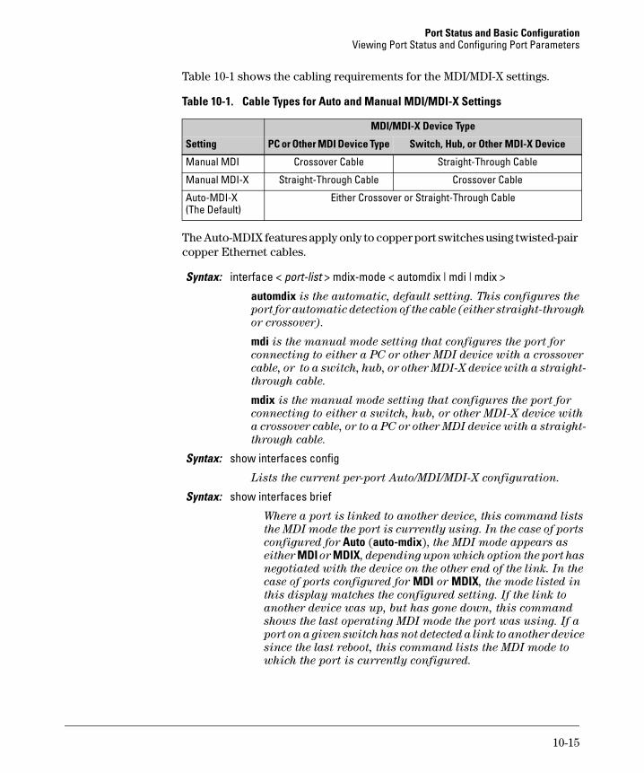
Table 10-1 shows the cabling requirements for the MDI/MDI-X settings.
Table 10-1. Cable Types for Auto and Manual MDI/MDI-X Settings
The Auto-MDIX features apply only to copper port switches using twisted-pair copper Ethernet cables.
MDI/MDI-X Device Type
Setting PC or Other MDI Device Type Switch, Hub, or Other MDI-X Device
Manual MDI Crossover Cable Straight-Through Cable
Manual MDI-X Straight-Through Cable Crossover Cable
Auto-MDI-X (The Default)
Either Crossover or Straight-Through Cable
Syntax: interface < port-list > mdix-mode < automdix | mdi | mdix >
automdix is the automatic, default setting. This configures the
port for automatic detection of the cable (either straight-through
or crossover).
mdi is the manual mode setting that configures the port for
connecting to either a PC or other MDI device with a crossover
cable, or to a switch, hub, or other MDI-X device with a straight-
through cable.
mdix is the manual mode setting that configures the port for
connecting to either a switch, hub, or other MDI-X device with
a crossover cable, or to a PC or other MDI device with a straight-
through cable.
Syntax: show interfaces config
Lists the current per-port Auto/MDI/MDI-X configuration.
Syntax: show interfaces brief
Where a port is linked to another device, this command lists
the MDI mode the port is currently using. In the case of ports
configured for Auto (auto-mdix), the MDI mode appears as
either MDI or MDIX, depending upon which option the port has
negotiated with the device on the other end of the link. In the
case of ports configured for MDI or MDIX, the mode listed in
this display matches the configured setting. If the link to
another device was up, but has gone down, this command
shows the last operating MDI mode the port was using. If a
port on a given switch has not detected a link to another device
since the last reboot, this command lists the MDI mode to
which the port is currently configured.
10-15
Port Status and Basic Configuration Viewing Port Status and Configuring Port Parameters
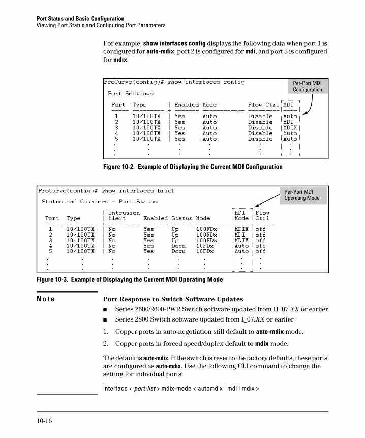
For example, show interfaces config displays the following data when port 1 is configured for auto-mdix, port 2 is configured for mdi, and port 3 is configured for mdix.
Figure 10-2. Example of Displaying the Current MDI Configuration
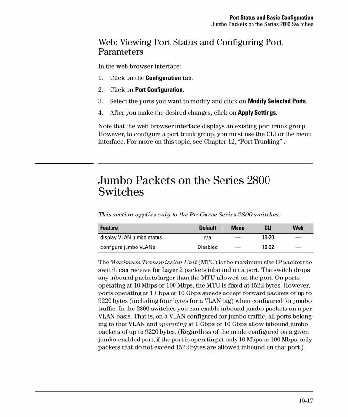
Figure 10-3. Example of Displaying the Current MDI Operating Mode
N o t e Port Response to Switch Software Updates
■ Series 2600/2600-PWR Switch software updated from H_07.XX or earlier
■ Series 2800 Switch software updated from I_07.XX or earlier
1. Copper ports in auto-negotiation still default to auto-mdix mode.
2. Copper ports in forced speed/duplex default to mdix mode.
The default is auto-mdix. If the switch is reset to the factory defaults, these ports are configured as auto-mdix. Use the following CLI command to change the setting for individual ports:
interface < port-list > mdix-mode < automdix | mdi | mdix >
Per-Port MDI Configuration
Per-Port MDI Operating Mode
10-16
Port Status and Basic ConfigurationJumbo Packets on the Series 2800 Switches
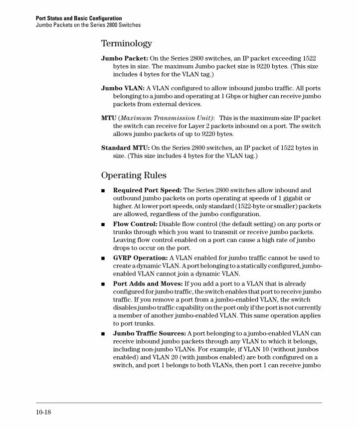
Web: Viewing Port Status and Configuring Port Parameters
In the web browser interface:
1. Click on the Configuration tab.
2. Click on Port Configuration.
3. Select the ports you want to modify and click on Modify Selected Ports.
4. After you make the desired changes, click on Apply Settings.
Note that the web browser interface displays an existing port trunk group. However, to configure a port trunk group, you must use the CLI or the menu interface. For more on this topic, see Chapter 12, “Port Trunking” .
Jumbo Packets on the Series 2800 Switches
This section applies only to the ProCurve Series 2800 switches.
The Maximum Transmission Unit (MTU) is the maximum size IP packet the switch can receive for Layer 2 packets inbound on a port. The switch drops any inbound packets larger than the MTU allowed on the port. On ports operating at 10 Mbps or 100 Mbps, the MTU is fixed at 1522 bytes. However, ports operating at 1 Gbps or 10 Gbps speeds accept forward packets of up to 9220 bytes (including four bytes for a VLAN tag) when configured for jumbo traffic. In the 2800 switches you can enable inbound jumbo packets on a per-VLAN basis. That is, on a VLAN configured for jumbo traffic, all ports belong-ing to that VLAN and operating at 1 Gbps or 10 Gbps allow inbound jumbo packets of up to 9220 bytes. (Regardless of the mode configured on a given jumbo-enabled port, if the port is operating at only 10 Mbps or 100 Mbps, only packets that do not exceed 1522 bytes are allowed inbound on that port.)
Feature Default Menu CLI Web
display VLAN jumbo status n/a — 10-20 —
configure jumbo VLANs Disabled — 10-22 —
10-17
Port Status and Basic Configuration Jumbo Packets on the Series 2800 Switches
Terminology
Jumbo Packet: On the Series 2800 switches, an IP packet exceeding 1522 bytes in size. The maximum Jumbo packet size is 9220 bytes. (This size includes 4 bytes for the VLAN tag.)
Jumbo VLAN: A VLAN configured to allow inbound jumbo traffic. All ports belonging to a jumbo and operating at 1 Gbps or higher can receive jumbo packets from external devices.
MTU (Maximum Transmission Unit): This is the maximum-size IP packet the switch can receive for Layer 2 packets inbound on a port. The switch allows jumbo packets of up to 9220 bytes.
Standard MTU: On the Series 2800 switches, an IP packet of 1522 bytes in size. (This size includes 4 bytes for the VLAN tag.)
Operating Rules
■ Required Port Speed: The Series 2800 switches allow inbound and outbound jumbo packets on ports operating at speeds of 1 gigabit or higher. At lower port speeds, only standard (1522-byte or smaller) packets are allowed, regardless of the jumbo configuration.
■ Flow Control: Disable flow control (the default setting) on any ports or trunks through which you want to transmit or receive jumbo packets. Leaving flow control enabled on a port can cause a high rate of jumbo drops to occur on the port.
■ GVRP Operation: A VLAN enabled for jumbo traffic cannot be used to create a dynamic VLAN. A port belonging to a statically configured, jumbo-enabled VLAN cannot join a dynamic VLAN.
■ Port Adds and Moves: If you add a port to a VLAN that is already configured for jumbo traffic, the switch enables that port to receive jumbo traffic. If you remove a port from a jumbo-enabled VLAN, the switch disables jumbo traffic capability on the port only if the port is not currently a member of another jumbo-enabled VLAN. This same operation applies to port trunks.
■ Jumbo Traffic Sources: A port belonging to a jumbo-enabled VLAN can receive inbound jumbo packets through any VLAN to which it belongs, including non-jumbo VLANs. For example, if VLAN 10 (without jumbos enabled) and VLAN 20 (with jumbos enabled) are both configured on a switch, and port 1 belongs to both VLANs, then port 1 can receive jumbo
10-18
Port Status and Basic ConfigurationJumbo Packets on the Series 2800 Switches
traffic from devices on either VLAN. For a method to allow only some ports in a VLAN to receive jumbo traffic, refer to “Operating Notes for Jumbo Traffic-Handling” on page 10-22.
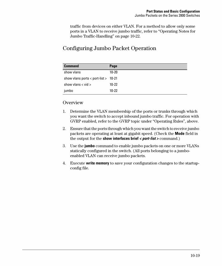
Configuring Jumbo Packet Operation
Overview
1. Determine the VLAN membership of the ports or trunks through which you want the switch to accept inbound jumbo traffic. For operation with GVRP enabled, refer to the GVRP topic under “Operating Rules”, above.
2. Ensure that the ports through which you want the switch to receive jumbo packets are operating at least at gigabit speed. (Check the Mode field in the output for the show interfaces brief < port-list > command.)
3. Use the jumbo command to enable jumbo packets on one or more VLANs statically configured in the switch. (All ports belonging to a jumbo-enabled VLAN can receive jumbo packets.
4. Execute write memory to save your configuration changes to the startup-config file.
Command Page
show vlans 10-20
show vlans ports < port-list > 10-21
show vlans < vid > 10-22
jumbo 10-22
10-19
Port Status and Basic Configuration Jumbo Packets on the Series 2800 Switches
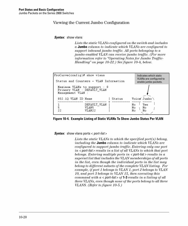
Viewing the Current Jumbo Configuration
Figure 10-4. Example Listing of Static VLANs To Show Jumbo Status Per VLAN
Syntax: show vlans
Lists the static VLANs configured on the switch and includes
a Jumbo column to indicate which VLANs are configured to
support inbound jumbo traffic. All ports belonging to a
jumbo-enabled VLAN can receive jumbo traffic. (For more
information refer to “Operating Notes for Jumbo Traffic-
Handling” on page 10-22.) See figure 10-4, below.
Syntax: show vlans ports < port-list >
Lists the static VLANs to which the specified port(s) belong,
including the Jumbo column to indicate which VLANs are
configured to support jumbo traffic. Entering only one port
in < port-list > results in a list of all VLANs to which that port
belongs. Entering multiple ports in < port-list > results in a
superset list that includes the VLAN memberships of all ports
in the list, even though the individual ports in the list may
belong to different subsets of the complete VLAN listing. For
example, if port 1 belongs to VLAN 1, port 2 belongs to VLAN
10, and port 3 belongs to VLAN 15, then executing this
command with a < port-list > of 1-3 results in a listing of all
three VLANs, even though none of the ports belong to all three
VLANS. (Refer to figure 10-5.)
Indicates which static VLANs are configured to enable jumbo packets.
10-20
Port Status and Basic ConfigurationJumbo Packets on the Series 2800 Switches
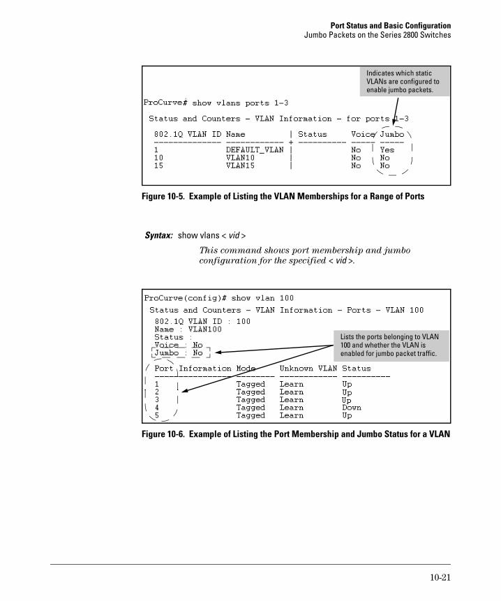
Figure 10-5. Example of Listing the VLAN Memberships for a Range of Ports
Figure 10-6. Example of Listing the Port Membership and Jumbo Status for a VLAN
Syntax: show vlans < vid >
This command shows port membership and jumbo
configuration for the specified < vid >.
Indicates which static VLANs are configured to enable jumbo packets.
Lists the ports belonging to VLAN 100 and whether the VLAN is enabled for jumbo packet traffic.
10-21
Port Status and Basic Configuration Jumbo Packets on the Series 2800 Switches
Enabling or Disabling Jumbo Traffic on a VLAN
Operating Notes for Jumbo Traffic-Handling
■ ProCurve does not recommend configuring a voice VLAN to accept jumbo packets. Voice VLAN packets are typically small, and allowing a voice VLAN to accept jumbo packet traffic can degrade the voice transmission performance.
■ You can configure the default, primary, and/or (if configured) the manage-ment VLAN to accept jumbo packets on all ports belonging to the VLAN.
■ When the switch applies the default MTU (1522-bytes) to a VLAN, all ports in the VLAN can receive incoming packets of up to 1522 bytes in length. When the switch applies the jumbo MTU (9220 bytes) to a VLAN, all ports in that VLAN can receive incoming packets of up to 9220 bytes in length. A port receiving packets exceeding the applicable MTU drops such pack-ets, causing the switch to generate an Event Log message and increment the “Giant Rx” counter (displayed by show interfaces < port-list >).
■ The switch does not allow flow control and jumbo packet capability to co-exist on a port. Attempting to configure both on the same port gener-ates an error message in the CLI and sends a similar message to the Event Log.
■ The default MTU on the Series 2800 switches is 1522 bytes (including 4 bytes for the VLAN tag). The jumbo MTU is 9220 bytes (including 4 bytes for the VLAN tag).
Syntax: vlan < vid > jumbo[ no ] vlan < vid > jumbo
Configures the specified VLAN to allow jumbo packets on all
ports on the switch that belong to that VLAN. If the VLAN is
not already configured on the switch, vlan < vid > jumbo also
creates the VLAN. Note that a port belonging to one jumbo
VLAN can receive jumbo packets through any other VLAN
statically configured on the switch, regardless of whether the
other VLAN is enabled for jumbo packets. The [no] form of the
command disables inbound jumbo traffic on all ports in the
specified VLAN that do not also belong to another VLAN that
is enabled for jumbo traffic. In a VLAN context, the command
forms are jumbo and no jumbo. (Default: Jumbos disabled on
the specified VLAN.)
10-22
Port Status and Basic ConfigurationJumbo Packets on the Series 2800 Switches
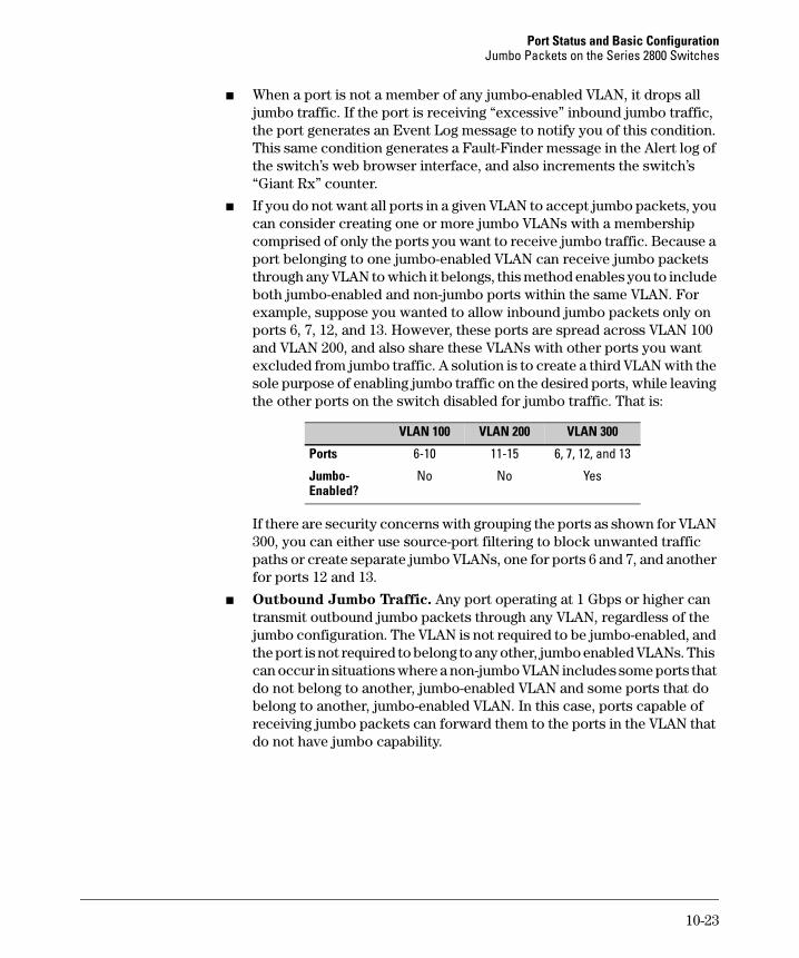
■ When a port is not a member of any jumbo-enabled VLAN, it drops all jumbo traffic. If the port is receiving “excessive” inbound jumbo traffic, the port generates an Event Log message to notify you of this condition. This same condition generates a Fault-Finder message in the Alert log of the switch’s web browser interface, and also increments the switch’s “Giant Rx” counter.
■ If you do not want all ports in a given VLAN to accept jumbo packets, you can consider creating one or more jumbo VLANs with a membership comprised of only the ports you want to receive jumbo traffic. Because a port belonging to one jumbo-enabled VLAN can receive jumbo packets through any VLAN to which it belongs, this method enables you to include both jumbo-enabled and non-jumbo ports within the same VLAN. For example, suppose you wanted to allow inbound jumbo packets only on ports 6, 7, 12, and 13. However, these ports are spread across VLAN 100 and VLAN 200, and also share these VLANs with other ports you want excluded from jumbo traffic. A solution is to create a third VLAN with the sole purpose of enabling jumbo traffic on the desired ports, while leaving the other ports on the switch disabled for jumbo traffic. That is:
If there are security concerns with grouping the ports as shown for VLAN 300, you can either use source-port filtering to block unwanted traffic paths or create separate jumbo VLANs, one for ports 6 and 7, and another for ports 12 and 13.
■ Outbound Jumbo Traffic. Any port operating at 1 Gbps or higher can transmit outbound jumbo packets through any VLAN, regardless of the jumbo configuration. The VLAN is not required to be jumbo-enabled, and the port is not required to belong to any other, jumbo enabled VLANs. This can occur in situations where a non-jumbo VLAN includes some ports that do not belong to another, jumbo-enabled VLAN and some ports that do belong to another, jumbo-enabled VLAN. In this case, ports capable of receiving jumbo packets can forward them to the ports in the VLAN that do not have jumbo capability.
VLAN 100 VLAN 200 VLAN 300
Ports 6-10 11-15 6, 7, 12, and 13
Jumbo- Enabled?
No No Yes
10-23
Port Status and Basic Configuration Jumbo Packets on the Series 2800 Switches
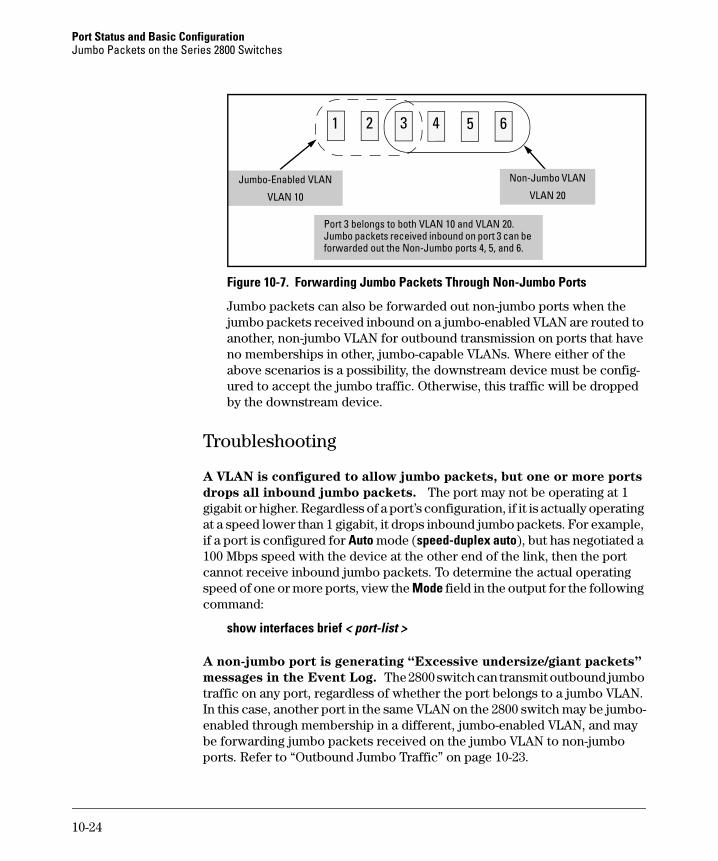
Figure 10-7. Forwarding Jumbo Packets Through Non-Jumbo Ports
Jumbo packets can also be forwarded out non-jumbo ports when the jumbo packets received inbound on a jumbo-enabled VLAN are routed to another, non-jumbo VLAN for outbound transmission on ports that have no memberships in other, jumbo-capable VLANs. Where either of the above scenarios is a possibility, the downstream device must be config-ured to accept the jumbo traffic. Otherwise, this traffic will be dropped by the downstream device.
Troubleshooting
A VLAN is configured to allow jumbo packets, but one or more ports
drops all inbound jumbo packets. The port may not be operating at 1 gigabit or higher. Regardless of a port’s configuration, if it is actually operating at a speed lower than 1 gigabit, it drops inbound jumbo packets. For example, if a port is configured for Auto mode (speed-duplex auto), but has negotiated a 100 Mbps speed with the device at the other end of the link, then the port cannot receive inbound jumbo packets. To determine the actual operating speed of one or more ports, view the Mode field in the output for the following command:
show interfaces brief < port-list >
A non-jumbo port is generating “Excessive undersize/giant packets”
messages in the Event Log. The 2800 switch can transmit outbound jumbo traffic on any port, regardless of whether the port belongs to a jumbo VLAN. In this case, another port in the same VLAN on the 2800 switch may be jumbo-enabled through membership in a different, jumbo-enabled VLAN, and may be forwarding jumbo packets received on the jumbo VLAN to non-jumbo ports. Refer to “Outbound Jumbo Traffic” on page 10-23.
Jumbo-Enabled VLAN
VLAN 10
Non-Jumbo VLAN
VLAN 20
Port 3 belongs to both VLAN 10 and VLAN 20. Jumbo packets received inbound on port 3 can be forwarded out the Non-Jumbo ports 4, 5, and 6.
1 52 3 4 6
10-24
Port Status and Basic ConfigurationQoS Pass-Through Mode on the Series 2800 and 4100gl Switches
QoS Pass-Through Mode on the Series 2800 and 4100gl Switches
QoS Pass-Through mode is designed to enhance the performance of line-rate traffic transfers through the Series 2800 and 4100gl switches. This feature should only be used in environments where Quality of Service (QoS) is not of major importance, but where lossless data transfers are key. This command disables any discrimination of QoS queues for traffic, consolidating packet buffer memory to provide line-rate flows with no loss of data.
General Operation
The port buffering design for the switch has been optimized for gigabit-to-gigabit traffic flows. For this reason, some flows from Gigabit-to-100Base or even 100Base-to-10Base may not perform as well as would be expected. The QoS Pass-Through mode enhancement can provide a significant performance improvement for high-bandwidth traffic flows through the switch, particularly when running traffic flows from 1000Base to either 100Base or 10Base connec-tions.
QoS Pass-Through mode is OFF by default, and must be enabled via the “config” context of the CLI by entering the CLI command qos-passthrough-mode, followed by write memory and rebooting the switch.
QoS Pass-Through mode, when enabled, results in the following general changes to switch operation:
■ Alters the switch's default outbound priority queue scheme from four queues (low, normal, medium, and high), to two queues (normal & high).
■ Optimizes outbound port buffers for a two-queue scheme.
■ All packets received with an 802.1p priority tag of 0 to 5 (low, normal, or medium priorities), or tagged by the switch's QOS feature, will be serviced by the (now larger) "normal" priority queue.
■ All packets received with an 802.1p priority tag of 6 or 7 (high priority), or tagged by the switch's QoS feature, will be serviced by the "high" priority queue.
■ High priority packets sourced by the switch itself, such as Spanning Tree packets, will be serviced in the "high" priority queue.
10-25
Port Status and Basic Configuration QoS Pass-Through Mode on the Series 2800 and 4100gl Switches
■ Any 802.1p tagging on a received packet, or any tag added to a received frame by the switch via its QoS configuration, will be preserved as it is transmitted from the switch.
NOTE: As stated earlier, use of this QoS-Passthrough-Mode feature generally assumes that QoS tagged packets are not being sent through the switch. The receipt of priority 6 or 7 packets may in fact suffer packet drops depending on the traffic load of non-priority 6 or 7 packets.
Priority Mapping With and Without QoS Pass-Through Mode
The switch supports 802.1p VLAN tagging, which is used in conjunction with the outbound port priority queues to prioritize outbound traffic.
An 802.1Q VLAN tagged packet carries an 802.1p priority setting (0-7). If the switch receives a tagged packet, it is placed into the appropriate queue based on the frame's 802.1p priority setting. The mapping with/without QoS Pass-Through Mode is as follows:
How to enable/disable QoS Pass-Through Mode
QoS Pass-Through Mode is disabled by default, and is available only in I.07.52 and later switch software versions.
802.1p Priority Setting
Prioritization Queue Placement
Default QoS Setting
QoS Passthrough Mode
1 1 (low) 2 (normal)
2 1 (low) 2 (normal)
0 or Unspecified
2 (normal) 2 (normal)
3 2 (normal) 2 (normal)
4 3 (medium) 2 (normal)
5 3 (medium) 2 (normal)
6 4 (high) 4 (high)
7 4 (high) 4 (high)
10-26
Port Status and Basic ConfigurationQoS Pass-Through Mode on the Series 2800 and 4100gl Switches
For example: ProCurve Switch 2824(config)# qos-passthrough-modeCommand will take effect after saving configuration and rebootProCurve Switch 2824(config)# write memoryProCurve Switch 2824(config)# reload
This command can be enabled and disabled only from the switch's CLI. QoS passthrough mode cannot be enabled or disabled through either the switch's menu or web browser interfaces.
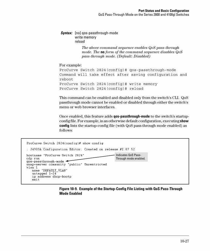
Once enabled, this feature adds qos-passthrough-mode to the switch’s startup-config file. For example, in an otherwise default configuration, executing show config lists the startup-config file (with QoS pass-through mode enabled) as follows:
Figure 10-9. Example of the Startup-Config File Listing with QoS Pass-Through Mode Enabled
Syntax: [no] qos-passthrough-modewrite memoryreload
The above command sequence enables QoS pass-through
mode. The no form of the command sequence disables QoS
pass-through mode. (Default: Disabled)
Indicates QoS Pass-Through mode enabled.
10-27
Port Status and Basic Configuration Configuring Port-Based Priority for Incoming Packets on the 4100gl and 6108 Switches
Configuring Port-Based Priority for Incoming Packets on the 4100gl and 6108 Switches
When network congestion occurs, it is important to move traffic on the basis of relative importance. However, without prioritization:
■ Traffic from less important sources can consume bandwidth and slow down or halt delivery of more important traffic.
■ Most traffic from all ports is forwarded as normal priority, and competes for bandwidth with all other normal-priority traffic, regardless of its relative importance.
Traffic received in tagged VLAN packets carries a specific 802.1p priority level (0 - 7) that the switch recognizes and uses to assign packet priority at the outbound port. With the default port-based priority, the switch handles traffic received in untagged packets as “Normal” (priority level = 0).
You can assign a priority level to:
■ Inbound, untagged VLAN packets
■ Inbound, tagged VLAN packets having a priority level of 0 (zero)
(The switch does not alter the existing priority level of inbound, tagged VLAN packets carrying a priority level of 1-7.)
Thus, for example, high-priority tagged VLAN traffic received on a port retains its priority in the switch. However, you have the option of configuring the port to assign a priority level to untagged traffic and 0-priority tagged traffic the port receives.
The Role of 802.1Q VLAN Tagging
An 802.1Q-tagged VLAN packet carries the packet’s VLAN assignment and the 802.1p priority setting (0 - 7). (By contrast, an untagged packet does not have a tag and does not carry a priority setting.) Generally, the switch preserves and uses a packet’s priority setting to determine which outbound queue the packet belongs in on the outbound port. If the outbound port is a tagged
Feature Default Menu CLI Web
Assigning a priority level to traffic on the basis of incoming port
Disabled n/a page 10-31 n/a
10-28
Port Status and Basic ConfigurationConfiguring Port-Based Priority for Incoming Packets on the 4100gl and 6108 Switches
member of the VLAN, the packet carries its priority setting to the next, downstream device. If the outbound port is not configured as a tagged member of the VLAN, then the tag is stripped from the packet, which then exits from the switch without a priority setting.
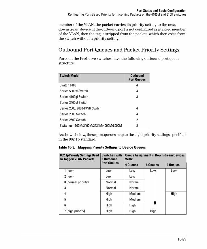
Outbound Port Queues and Packet Priority Settings
Ports on the ProCurve switches have the following outbound port queue structure:
As shown below, these port queues map to the eight priority settings specified in the 802.1p standard.
Table 10-3. Mapping Priority Settings to Device Queues
Switch Model OutboundPort Queues
Switch 6108 4
Series 5300xl Switch 4
Series 4100gl Switch 3
Series 3400cl Switch
Series 2600, 2600-PWR Switch 4
Series 2800 Switch 4
Series 2500 Switch 2
Switches 1600M/2400M/2424M/4000M/8000M 2
802.1p Priority Settings Used In Tagged VLAN Packets
Switches with 3 Outbound Port Queues
Queue Assignment in Downstream Devices With:
4 Queues 8 Queues 2 Queues
1 (low) Low Low Low Low
2 (low) Low Low
0 (normal priority) Normal Normal
3 Normal Normal
4 High Medium High
5 High Medium
6 High High
7 (high priority) High High High
10-29
Port Status and Basic Configuration Configuring Port-Based Priority for Incoming Packets on the 4100gl and 6108 Switches
For example, suppose you have configured port A10 to assign a priority level of 1 (low):
■ An untagged packet coming into the switch on port A10 and leaving the switch through any other port configured as a tagged VLAN member would leave the switch as a tagged packet with a priority level of 1.
■ A tagged packet with an 802.1p priority setting of 0 (zero) coming into the switch on port A10 and leaving the switch through any other port config-ured as a tagged VLAN member would leave the switch as a tagged packet with a priority level of 1.
■ A tagged packet with an 802.1p priority setting (1 - 7) coming into the switch on port A10 and leaving the switch through any other port config-ured as a tagged VLAN member would keep its original priority setting (regardless of the port-based priority setting on port A10).
N o t e For a packet to carry a given 802.1p priority level from end-to-end in a network, the VLAN for the packet must be configured as tagged on all switch-to-switch links. Otherwise the tag is removed and the 802.1p priority is lost as the packet moves from one switch to the next.
Operating Rules for Port-Based Priority
These rules apply to the operation of port-based priority on the switch.
■ In the switch’s default configuration, port-based priority is configured as “0” (zero) for inbound traffic on all ports.
■ On a given port, when port-based priority is configured as 0 - 7, an inbound, untagged packet adopts the specified priority and is sent to the corresponding outbound queue on the outbound port. (See table 10-3, “Mapping Priority Settings to Device Queues”, on page 10-29.) If the outbound port is a tagged member of the applicable VLAN, then the packet carries a tag with that priority setting to the next downstream device.
■ On a given port, when port-based priority is configured as 0 - 7, an inbound, tagged packet with a priority of 0 (zero) adopts the specified priority and is sent to the corresponding outbound queue on the outbound port. (See table 10-3, “Mapping Priority Settings to Device Queues”, on page 10-29.) If the outbound port is a tagged member of the applicable VLAN, then the packet carries a tag with that priority setting to the next downstream device.
10-30
Port Status and Basic ConfigurationConfiguring Port-Based Priority for Incoming Packets on the 4100gl and 6108 Switches
■ On a given port, an inbound, tagged packet received on the port with a preset priority of 1 - 7 in its tag keeps that priority and is assigned an outbound queue on the basis of that priority (regardless of the port-based priority configured on the port). (Refer to table 10-3, “Mapping Priority Settings to Device Queues” on page 10-29.)
■ If a packet leaves the switch through an outbound port configured as an untagged member of the packet’s VLAN, then the packet leaves the switch without a VLAN tag and thus without an 802.1p priority setting.
■ Trunked ports do not allow non-default (1 - 7) port-based priority settings. If you configure a non-default port-based priority value on a port and then add the port to a port trunk, then the port-based priority for that port is returned to the default “0”.
Configuring and Viewing Port-Based Priority
This command enables or disables port-based priority on a per-port basis. You can either enter the command on the interface context level or include the interface in the command.
Syntax: interface <port #> qos priority < 1 .. 7 >
Configures a non-default port-based 802.1p priority for incoming, untagged packets or tagged packets arriving with
a "0" priority on the designated ports, as described under
"Operating Rules for Port-Based Priority", above.
interface <port #> qos priority 0
Returns a port-based priority setting to the default "0" for
untagged packets received on the designated port(s). In this
state the switch handles the untagged packets with "Normal"
priority. (Refer to table 10-3 on page 10-29.)
show running-config
Lists any non-default (1 - 7) port-based priority settings in
the running-config file on a per-port basis. If the priority is
set to the (default) "0", the setting is not included in the show config listing.
show config
Lists any non-default (1 - 7) port-based priority settings in
the startup-config file on a per-port basis. If the priority is set
to the (default) "0", the setting is not included in the show config listing.
10-31
Port Status and Basic Configuration Configuring Port-Based Priority for Incoming Packets on the 4100gl and 6108 Switches
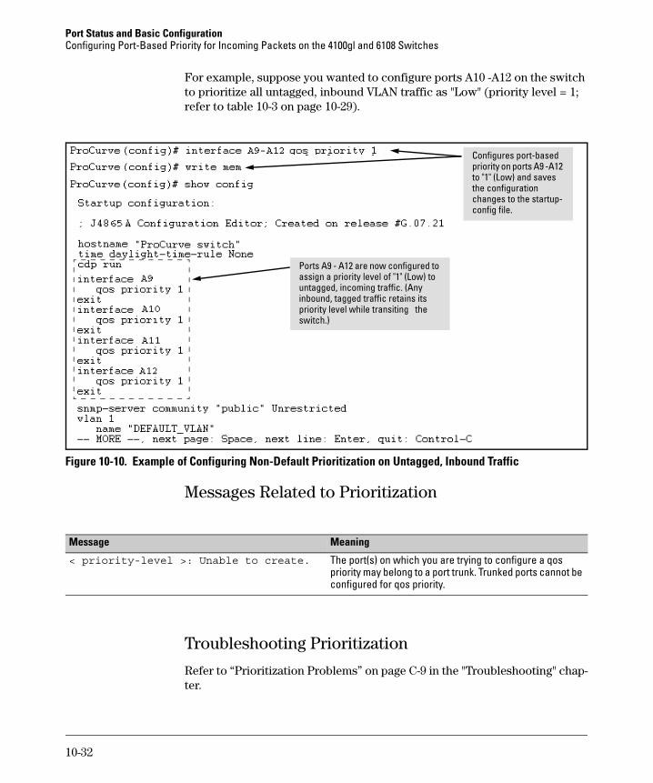
For example, suppose you wanted to configure ports A10 -A12 on the switch to prioritize all untagged, inbound VLAN traffic as "Low" (priority level = 1; refer to table 10-3 on page 10-29).
Figure 10-10. Example of Configuring Non-Default Prioritization on Untagged, Inbound Traffic
Messages Related to Prioritization
Troubleshooting Prioritization
Refer to “Prioritization Problems” on page C-9 in the "Troubleshooting" chap-ter.
Ports A9 - A12 are now configured to assign a priority level of "1" (Low) to untagged, incoming traffic. (Any inbound, tagged traffic retains its priority level while transiting the switch.)
Configures port-based priority on ports A9 -A12 to "1" (Low) and saves the configuration changes to the startup-config file.
Message Meaning
< priority-level >: Unable to create. The port(s) on which you are trying to configure a qos priority may belong to a port trunk. Trunked ports cannot be configured for qos priority.
10-32
Port Status and Basic ConfigurationUsing Friendly (Optional) Port Names
Using Friendly (Optional) Port Names
This feature enables you to assign alphanumeric port names of your choosing to augment automatically assigned numeric port names. This means you can configure meaningful port names to make it easier to identify the source of information listed by some Show commands. (Note that this feature augments port numbering, but does not replace it.)
Configuring and Operating Rules for Friendly Port Names
■ At either the global or context configuration level you can assign a unique name to any port on the switch. You can also assign the same name to multiple ports.
■ The friendly port names you configure appear in the output of the show name [port-list], show config, and show interface <port-number> commands. They do not appear in the output of other show commands or in Menu interface screens. (See “Displaying Friendly Port Names with Other Port Data” on page 10-36.)
■ Friendly port names are not a substitute for port numbers in CLI com-mands or Menu displays.
■ Trunking ports together does not affect friendly naming for the individual ports. (If you want the same name for all ports in a trunk, you must individually assign the name to each port.)
■ A friendly port name can have up to 64 contiguous alphanumeric charac-ters.
■ Blank spaces within friendly port names are not allowed, and if used, cause an invalid input error. (The switch interprets a blank space as a name terminator.)
■ In a port listing, not assigned indicates that the port does not have a name assignment other than its fixed port number.
Feature Default Menu CLI Web
Configure Friendly Port Names Standard Port Numbering
n/a page 34 n/a
Display Friendly Port Names n/a n/a page 36 n/a
10-33
Port Status and Basic Configuration Using Friendly (Optional) Port Names
■ To retain friendly port names across reboots, you must save the current running-configuration to the startup-config file after entering the friendly port names. (In the CLI, use the write memory command.)
Configuring Friendly Port Names
Syntax: interface <port-list> name <port-name-string>Assigns a port name to port-list.
no interface <port-list> nameDeletes the port name from port-list.
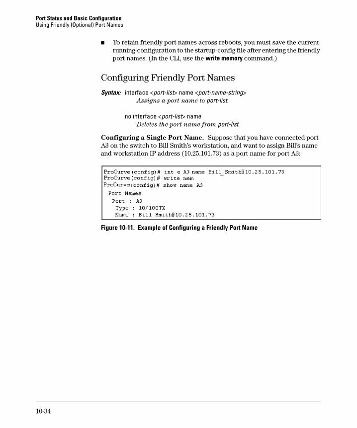
Configuring a Single Port Name. Suppose that you have connected port A3 on the switch to Bill Smith’s workstation, and want to assign Bill’s name and workstation IP address (10.25.101.73) as a port name for port A3:
Figure 10-11. Example of Configuring a Friendly Port Name
10-34
Port Status and Basic ConfigurationUsing Friendly (Optional) Port Names
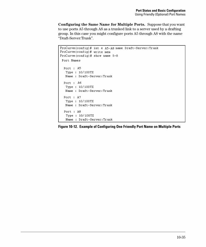
Configuring the Same Name for Multiple Ports. Suppose that you want to use ports A5 through A8 as a trunked link to a server used by a drafting group. In this case you might configure ports A5 through A8 with the name “Draft-Server:Trunk”.
Figure 10-12. Example of Configuring One Friendly Port Name on Multiple Ports
10-35
Port Status and Basic Configuration Using Friendly (Optional) Port Names
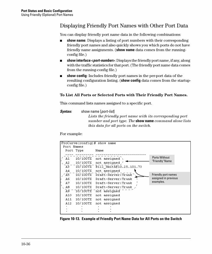
Displaying Friendly Port Names with Other Port Data
You can display friendly port name data in the following combinations:
■ show name: Displays a listing of port numbers with their corresponding friendly port names and also quickly shows you which ports do not have friendly name assignments. (show name data comes from the running-config file.)
■ show interface <port-number>: Displays the friendly port name, if any, along with the traffic statistics for that port. (The friendly port name data comes from the running-config file.)
■ show config: Includes friendly port names in the per-port data of the resulting configuration listing. (show config data comes from the startup-config file.)
To List All Ports or Selected Ports with Their Friendly Port Names.
This command lists names assigned to a specific port.
Syntax: show name [port-list]Lists the friendly port name with its corresponding port
number and port type. The show name command alone lists
this data for all ports on the switch.
For example:
Figure 10-13. Example of Friendly Port Name Data for All Ports on the Switch
Friendly port names assigned in previous examples.
Ports Without "Friendly" Name
10-36
Port Status and Basic ConfigurationUsing Friendly (Optional) Port Names
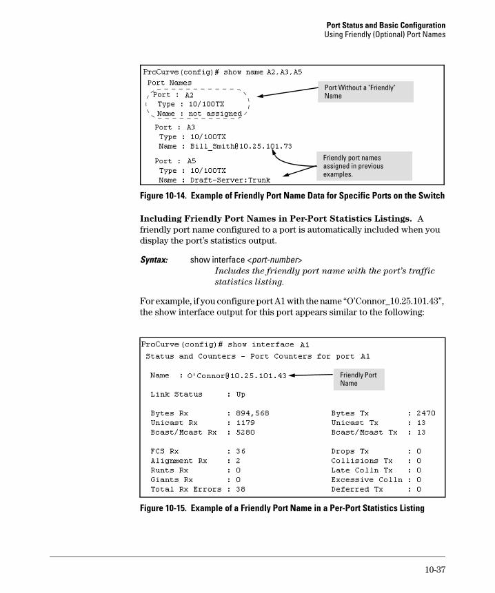
Figure 10-14. Example of Friendly Port Name Data for Specific Ports on the Switch
Including Friendly Port Names in Per-Port Statistics Listings. A friendly port name configured to a port is automatically included when you display the port’s statistics output.
Syntax: show interface <port-number>Includes the friendly port name with the port’s traffic
statistics listing.
For example, if you configure port A1 with the name “O’Connor_10.25.101.43”, the show interface output for this port appears similar to the following:
Figure 10-15. Example of a Friendly Port Name in a Per-Port Statistics Listing
Port Without a "Friendly" Name
Friendly port names assigned in previous examples.
Friendly Port Name
10-37
Port Status and Basic Configuration Using Friendly (Optional) Port Names
For a given port, if a friendly port name does not exist in the running-config file, the Name line in the above command output appears as:
Name : not assigned
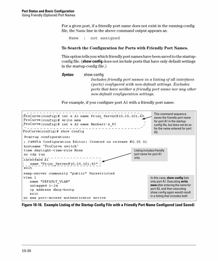
To Search the Configuration for Ports with Friendly Port Names.
This option tells you which friendly port names have been saved to the startup-config file. (show config does not include ports that have only default settings in the startup-config file.)
Syntax: show configIncludes friendly port names in a listing of all interfaces
(ports) configured with non-default settings. Excludes
ports that have neither a friendly port name nor any other
non-default configuration settings.
For example, if you configure port A1 with a friendly port name:
Figure 10-16. Example Listing of the Startup-Config File with a Friendly Port Name Configured (and Saved)
This command sequence saves the friendly port name for port A1 in the startup-config file, but does not do so for the name entered for port A2.
In this case, show config lists only port A1. Executing write mem after entering the name for port A2, and then executing show config again would result in a listing that includes both
Listing includes friendly port name for port A1 only.
10-38