Pore Scale Modelling of Porous Layers Used in Fuel Cells · Pore Scale Modelling of Porous Layers...
53
© Fraunhofer ITWM 1 Special Semester RICAM Linz 05.10.2011 Pore Scale Modelling of Porous Layers Used in Fuel Cells Jürgen Becker Fraunhofer Institute for Industrial Mathematics ITWM Kaiserslautern, Germany
Transcript of Pore Scale Modelling of Porous Layers Used in Fuel Cells · Pore Scale Modelling of Porous Layers...

© Fraunhofer ITWM1
Special Semester RICAM Linz 05.10.2011
Pore Scale Modelling of Porous Layers Used in Fuel Cells
Jürgen Becker
Fraunhofer Institute for Industrial Mathematics ITWM
Kaiserslautern, Germany

© Fraunhofer ITWM2
Pore Scale Modelling of Porous Layers Used in Fuel Cells
Department 'Flow and Material Simulation'
Groups:
Hydrodynamics and CFD
Complex Fluids
Micro-structure simulation and virtual material design
A. Wiegmann, S.Rief, L. Cheng, E. Glatt, N. Zamel. S. Linden
Mechanics of Materials

© Fraunhofer ITWM3
Outline
1. Introduction to PEM fuel cells
2. Pore scale modelling of porous layers used in fuel cells
a) Creation of virtual 3D structure models
b) Determination of effective properties
c) Validation
d) Some results
3. The general idea
4. Other fields of applications

© Fraunhofer ITWM4
Proton Exchange Membrane (PEM) Fuel Cell

© Fraunhofer ITWM5
Porous Layers in a PEM Fuel Cell
Gas Diffusion Layer
Micro-porous Layer
Catalyst Layer
Membrane
Find layers with optimal properties!
Properties of a porous medium are influenced by:
Material
Pore structure

© Fraunhofer ITWM6
Gas Diffusion Layer (GDL)
Carbon Fibers ( 7 µm diam.)
Teflon Coating
Pore Sizes ~ 30 µm
Thickness 200-400 µm
Optional:
Binder
Entangled Fibers
Filling
Alternative:
Woven Carbon Paper

© Fraunhofer ITWM7
Microporous Layer (MPL)
Carbon Agglomerates
Pore Sizes ~ 100 nm
Chun et al, Int. J. Hydrogen Energy 35, 2010

© Fraunhofer ITWM8
GDL and MPL

© Fraunhofer ITWM9
Catalyst Layer
Carbon Agglomerates
Ionomer
Platinum Particles
Pore Sizes ~ 100 nm
FIB-SEM image by S. Thiele, IMTEK Freiburg

© Fraunhofer ITWM10
Outline
1. Introduction to PEM fuel cells
2. Pore scale modelling of porous layers used in fuel cells
a) Creation of virtual 3D structure models
b) Determination of effective properties
c) Validation
d) Some results
3. The general idea
4. Other fields of applications

© Fraunhofer ITWM11
3D Structure Model
Two sources:1) Tomography image (segmentation)
(needed for validation)
2) Virtually generated (stochastic geometry)
(needed for virtual material design)

© Fraunhofer ITWM12
3D Models: Gas Diffusion Layer (GDL)
Nonwoven fibres
Input: Porosity Fibre diameter and type Anisotropy
Agorithm: Poisson line process
Production process not modeled

© Fraunhofer ITWM13
3D Models: Gas Diffusion Layer (GDL)
Nonwoven fibres plus binder
Input: Porosity Fibre diameter and type Anisotropy
Weight% binder

© Fraunhofer ITWM14
3D Models: Gas Diffusion Layer (GDL)
Nonwoven fibres (entangled)
Input: Porosity Fibre diameter and type Anisotropy
Fibre crimp

© Fraunhofer ITWM15
Curved Fibers
Idea: create curved fibres out of straight segments
Algorithm: 1. start with one segment2. add segments until desired fibre length is reached
How to determine the direction of the next segment? Many possibilities: keep previous direction + random deviation or: keep previous curvature + random deviation anisotropy of main fibre direction anisotropy of deviations

© Fraunhofer ITWM16
Curved Fibers
Determine fiber direction dn+1 :
α = 0 : maintain curvatureα = 1 : maintain direction
α=1, β=1:
Anisotropy:
α: "straightness"β: "force"σ: randomness

© Fraunhofer ITWM17
3D Models: Microporous Layer (MPL)
Typically: carbon agglomerates
Input: Particle size Particles per Agglomerate Porosity
Becker, Wieser, Fell, Steiner, Int J. Heat Mass Transfer2010

© Fraunhofer ITWM18
3D Models: Catalyst Layer (CL)
Carbon agglomerates plus electrolyte/ionomer
Elect. surrounds
C. particles
Elect. between
C. particles
Elect. surrounds
C. particles but
not in between

© Fraunhofer ITWM19
Model example:
Porosity 33.3 %Carbon/Pt 50.1 vol%Electrolyte 16.6 vol%
Size: (800 nm)³, voxel length 1 nm
3D Models: Catalyst Layer (CL)

© Fraunhofer ITWM20
Outline
1. Introduction to PEM fuel cells
2. Pore scale modelling of porous layers used in fuel cells
a) Creation of virtual 3D structure models
b) Determination of effective properties
c) Validation
d) Some results
3. The general idea
4. Other fields of applications
© Fraunhofer ITWM21
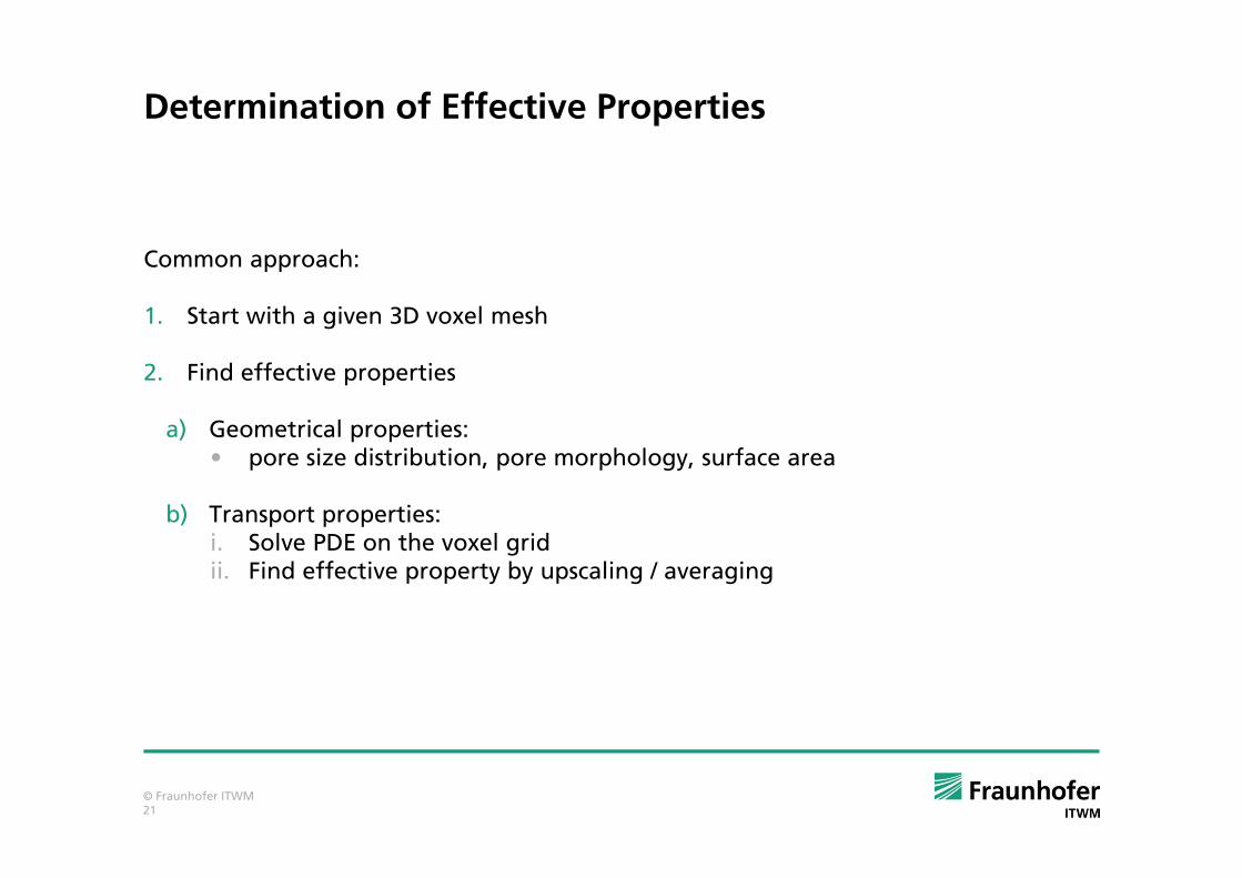
Determination of Effective Properties
Common approach:
1. Start with a given 3D voxel mesh
2. Find effective properties
a) Geometrical properties: • pore size distribution, pore morphology, surface area
b) Transport properties:i. Solve PDE on the voxel gridii. Find effective property by upscaling / averaging

© Fraunhofer ITWM22
Diffusivity
Macroscopic description (homogenized porous media model)Fick's first law:
D* : effective diffusivity [m²/s] unknownj : diffusion flux [mol/m²/s]c : concentration [mol/m³]
Microscopic description (pore structure model)Laplace equation:
Boundary conditions: no-flux on fibre surface, concentration drop
D* can be determined from the solution!
c=1
c=0

© Fraunhofer ITWM23
Knudsen Diffusivity
Macroscopic description (homogenized porous media model)Fick's first law:
D* : effective diffusivity [m²/s] unknownj : diffusion flux [mol/m²/s]c : concentration [mol/m³]
Diffusion mechanisms1. Kn << 1 (bulk diffusion) Diffusion by particle-particle collisions Mathematical model: Laplace equation
2. Kn >> 1 (Knudsen diffusion) Diffusion by particle-wall collisions Mathematical model: random walk methods
3. Kn ~ 1 (transition regime diffusion) Both mechanisms are present, Bosanquet:
[( )( ) ]2
TKn t o t oD E x x x x
t
ε= − −

© Fraunhofer ITWM24
Electric Conductivity
Macroscopic description (homogenized porous media model)Macroscopic description (homogenized porous media model)Macroscopic description (homogenized porous media model)Macroscopic description (homogenized porous media model)
Ohm’s law :
j : current density [A/m2]σ¤: effective conductivity [1/Ω/m]φ : potential [V]
Microscopic description (pore structure model)Microscopic description (pore structure model)Microscopic description (pore structure model)Microscopic description (pore structure model)
Conduction equation:
Boundary conditions: potential drop
σ* can be determined from the solution!

© Fraunhofer ITWM25
Permeability
Macroscopic description (homogenized porous media model)
Darcy’s law :
u : average flow velocityκ : permeability tensor unknownµ : viscosityp : pressure
Microscopic description (pore structure model)
Stokes equation:
Boundary conditions: no-slip on fibre surface, pressure dropκ can be determined from the solution!

© Fraunhofer ITWM26
Two-step approach:
1. Use pore morphology method (Hilpert, 2001) to determine distribution of air and water phase.
Idea: a pore is filled with the non-wetting fluid (=water), if
2. Solve Stokes equation on the remaining pore space to determine wetting phase (=air) permebility
Relative Permeability
non-wetting fluid
wetting fluid
r
β

© Fraunhofer ITWM27
Properties Overview
GDL: (saturation dependent) diffusivity, (saturation dependent) permeability, electric conductivity, heat conductivity pore size distribution
MPL (Knudsen) diffusivity, electric conductivity, heat conductivity pore size distribution
CL pore size distribution, surface or contact areas, contact lines protonic conductivity, electronic conductivity, (Knudsen) diffusivity
Caveat: Results cannot be better than the 3D structure model permits.

© Fraunhofer ITWM28
Outline
1. Introduction to PEM fuel cells
2. Pore scale modelling of porous layers used in fuel cells
a) Creation of virtual 3D structure models
b) Determination of effective properties
c) Validation
d) Some results
3. The general idea
4. Other fields of applications

© Fraunhofer ITWM29
Validation: Toray TGP H 060 Gas Diffusion Layer
Data from PSI: Tomography images of Toray TGP H 060 at different compression levels Diffusivity, permeability and conductivity were measured at different compression levels experimentally
Now: compute diffusivity, permeability and conductivity numerically and compare results
Becker, Flückiger, Reum, Büchi, Marone, Stampanoni, 2009, J. Electrochem. Soc. 156
© Fraunhofer ITWM30
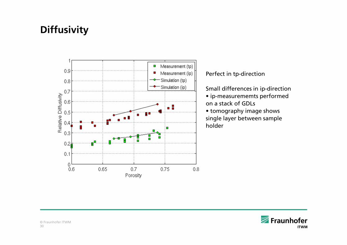
Diffusivity
Perfect in tp-direction
Small differences in ip-direction
• ip-measurememts performed
on a stack of GDLs
• tomography image shows
single layer between sample
holder

© Fraunhofer ITWM31
Permeability
Perfect in tp-direction
Small differences in ip-direction
• ip-measurememts performed
on a stack of GDLs
• tomography image shows
single layer between sample
holder
© Fraunhofer ITWM32
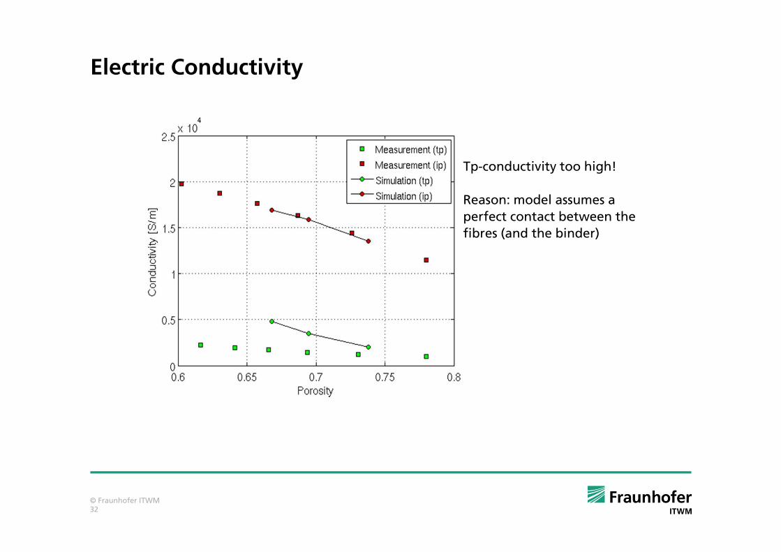
Electric Conductivity
Tp-conductivity too high!
Reason: model assumes a
perfect contact between the
fibres (and the binder)

© Fraunhofer ITWM33
Outline
1. Introduction to PEM fuel cells
2. Pore scale modelling of porous layers used in fuel cells
a) Creation of virtual 3D structure models
b) Determination of effective properties
c) Validation
d) Some results
3. The general idea
4. Other fields of applications

© Fraunhofer ITWM34
Comparison of GDL Designs
same fibre diameters
different orientations
all fibres in-plane
isotropic
in-plane + through-plane
Zamel, Li, Shen, Becker, Wiegmann, Chem. Engineering Sci. 65, pp 3994-4006, 2010.

© Fraunhofer ITWM35
Comparison of Different MPL
Create MPLs with
same porosity & particle sizes
different pore size distributions

© Fraunhofer ITWM36
Comparison of Different MPL
Case Conductivity Diffusivity
I 0.094 1.92
II 0.120 1.78
III 0.104 1.65
IV 0.092 1.59
V 0.095 1.67
© Fraunhofer ITWM37
Outline
1. Introduction to PEM fuel cells
2. Pore scale modelling of porous layers used in fuel cells
a) Creation of virtual 3D structure models
b) Determination of effective properties
c) Validation
d) Some results
3. The general idea
4. Other fields of applications

© Fraunhofer ITWM38
The General Approach: Computer Aided Material Engineering
Properties
Model
Properties
Voxel Mesh
generate
compute
measure
Properties are:• pore size distribution• permeability• diffusivity• capillary pressure curve• ...
Lab Computer
?
PorousMaterial
manufacturenext material
try nextset of
parameters

© Fraunhofer ITWM39
Validation - Step 1: Property Computations
Porous Material
Properties
CT Image
Voxel Mesh
Properties
compute
filter &segment
image
measure
compare
... and image acquisition
... and image processing
... and measurements

© Fraunhofer ITWM40
Validation - Step 2: Material Models
CT Image
Voxel Mesh
Model
Properties Properties
VoxelMesh
generate
computecompute
filter &segment
compare
© Fraunhofer ITWM41
filter &segment
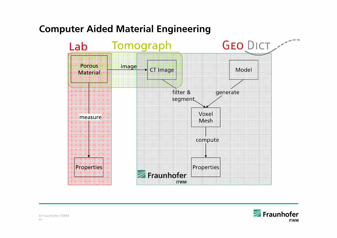
Computer Aided Material Engineering
Porous Material CT Image
Voxel Mesh
Model
Properties
generate
compute
Properties
image
measure
Lab Tomograph
© Fraunhofer ITWM42
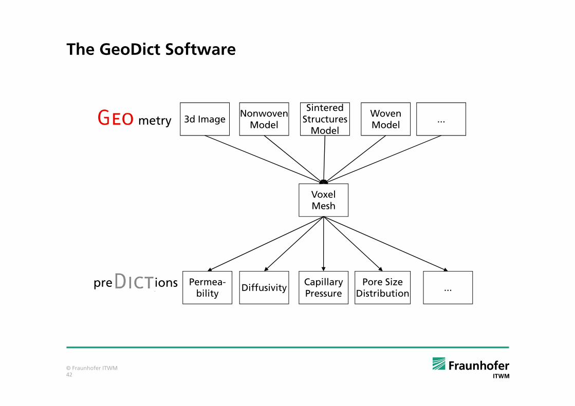
The GeoDict Software
3d Image
Voxel Mesh
NonwovenModel
Permea-bility
Sintered Structures
Model
Woven Model
DiffusivityCapillary Pressure
Pore Size Distribution
metry
pre ions
...
...

© Fraunhofer ITWM43
Modules of the GeoDict Software
Generators:Generators:Generators:Generators:
- FiberFiberFiberFiberGeo Geo Geo Geo
- SinterSinterSinterSinterGeoGeoGeoGeo
- WeaveWeaveWeaveWeaveGeoGeoGeoGeo
- GridGridGridGridGeoGeoGeoGeo
- PackPackPackPackGeo Geo Geo Geo
- PleatPleatPleatPleatGeo Geo Geo Geo
- PaperPaperPaperPaperGeo Geo Geo Geo
Modifiers:Modifiers:Modifiers:Modifiers:
- ProcessProcessProcessProcessGeoGeoGeoGeo (3d image processing)
- LayerLayerLayerLayerGeoGeoGeoGeo (layered media)
- ImportImportImportImportGeoGeoGeoGeo (e.g. tomographie, .stl)
- ExportExportExportExportGeoGeoGeoGeo (e.g. Fluent, Abaqus)
Simple Properties Predictors:Simple Properties Predictors:Simple Properties Predictors:Simple Properties Predictors:
- FlowFlowFlowFlowDictDictDictDict (single phase flow properties)
- ElastoElastoElastoElastoDictDictDictDict (effective elastic properties)
- ConductoConductoConductoConductoDictDictDictDict (effective conductivity)
- DiffuDiffuDiffuDiffuDictDictDictDict (effective diffusivity)
Complex Properties Predictors:Complex Properties Predictors:Complex Properties Predictors:Complex Properties Predictors:
- FilterFilterFilterFilterDictDictDictDict (pressure drop, efficiency, life time)
- SatuSatuSatuSatuDictDictDictDict (two phase flow properties)
- PoroPoroPoroPoroDictDictDictDict (pore size measures)
- AcoustoAcoustoAcoustoAcoustoDictDictDictDict (acoustic absorption)
- PleatPleatPleatPleatDictDictDictDict (porous media flow)

© Fraunhofer ITWM44
Outline
1. Introduction to PEM fuel cells
2. Pore scale modelling of porous layers used in fuel cells
a) Creation of virtual 3D structure models
b) Determination of effective properties
c) Validation
d) Some results
3. The general idea
4. Other fields of applications

© Fraunhofer ITWM45
Other Industrial Applications
Filtration
Paper dewatering felts
Sintered ceramics
Woven metal wire meshes
Diapers and hygiene products

© Fraunhofer ITWM46
Filtration

© Fraunhofer ITWM47
Tomography and Models of Felts
Tomography
Paper machine
1mm
10m
Forming fabric and dewatering felt
© Fraunhofer ITWM48
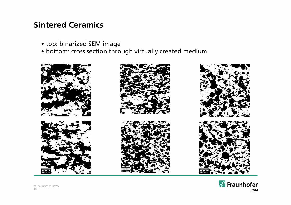
Sintered Ceramics
• top: binarized SEM image• bottom: cross section through virtually created medium
© Fraunhofer ITWM49
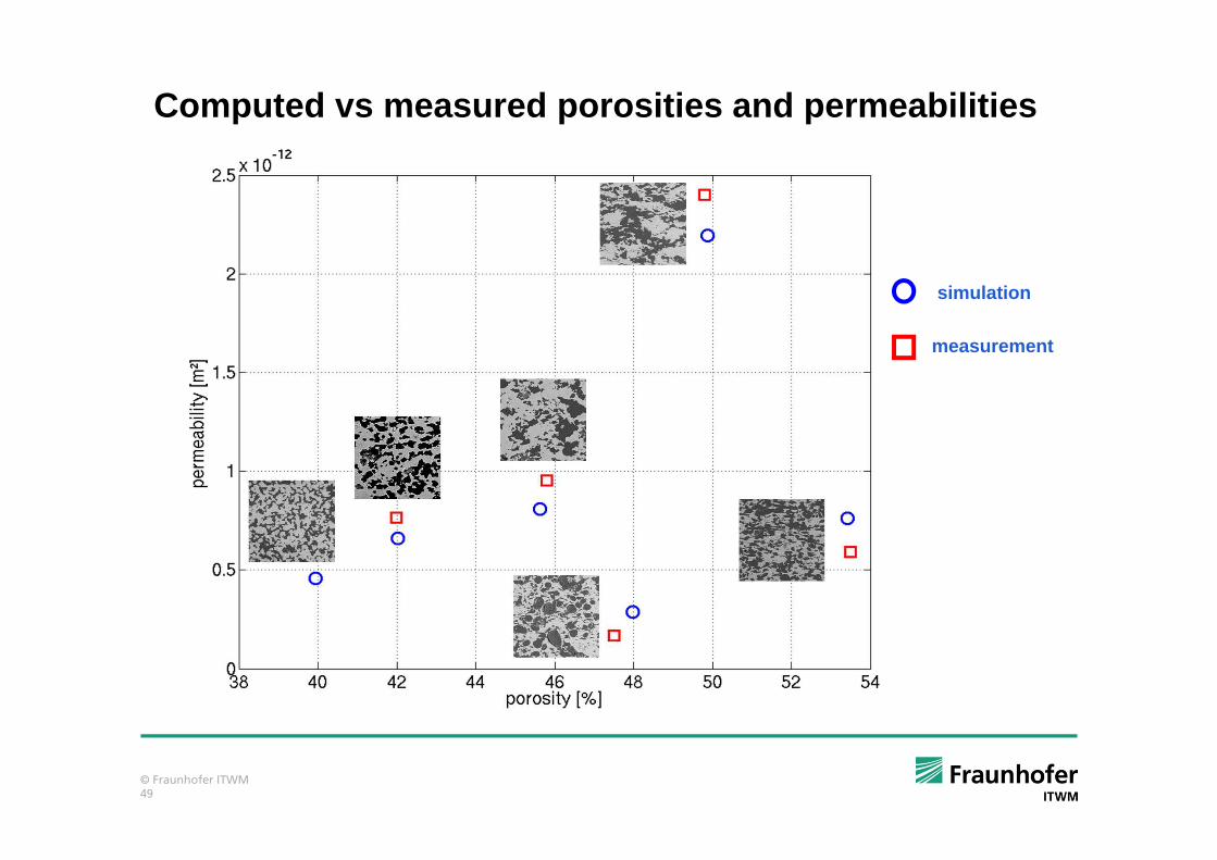
Computed vs measured porosities and permeabilities
simulation
measurement

© Fraunhofer ITWM50
Woven Metal Wire Meshes: Complex weave models
Left: Model of a two-layer weave based on a CT-scan.Right: Model of a complex one-layer twill Dutch-weave.

© Fraunhofer ITWM51
Woven Metal Wire Meshes: Geometric Validation
(a): CT of a twill Dutch-weave. (b): Geometry model. (c)-(d): Geometric validation.

© Fraunhofer ITWM52
Woven Metal Wire Meshes: Measurement and Simulation
Velocity dependent pressure drop: Comparison between measurements and simulationson corresponding geometry models.

© Fraunhofer ITWM53
Thank You !Geometry generator, property
predictor and virtual material
designer
www.geodict.com
BMBF project PemCaD


![Multiphase lattice Boltzmann simulations for porous media ... · Multiphase lattice Boltzmann simulations for porous media applications 3 the complex pore geometry [17], which restricts](https://static.fdocuments.net/doc/165x107/5e180bacad4ba146a6382852/multiphase-lattice-boltzmann-simulations-for-porous-media-multiphase-lattice.jpg)