
Polygon Subtraction in Two or Three Dimensions - pnnl.gov · one point on each output polygon that...
41
PNNL-SA-97135 Prepared for the U.S. Department of Energy under Contract DE-AC05-76RL01830 Polygon Subtraction in Two or Three Dimensions October 2013 JE Wilson
Transcript of Polygon Subtraction in Two or Three Dimensions - pnnl.gov · one point on each output polygon that...
PNNL-SA-97135
Prepared for the U.S. Department of Energy under Contract DE-AC05-76RL01830
Polygon Subtraction in Two or Three Dimensions
October 2013
JE Wilson
PNNL-SA-97135
Polygon Subtraction in Two or Three Dimensions
JE Wilson
October 2013
Prepared for
the U.S. Department of Energy
under Contract DE-AC05-76RL01830
Pacific Northwest National Laboratory
Richland, Washington 99352


iii
Summary
When searching for computer code to perform the ubiquitous task of subtracting one polygon from
another, it is difficult to find real examples or detailed explanations. This paper outlines the step-by-step
process necessary to accomplish this basic task.
Keywords: polygon subtraction algorithm, polygon difference algorithm, two-dimensions, and three-
dimensions.


v
Acknowledgments
I would like to thank my coworker, Lisa L. Newburn, for her valuable editing, research assistance,
and hard day-to-day work.


vii
Contents
Summary ............................................................................................................................................... iii
Acknowledgments ................................................................................................................................. v
1.0 Introduction .................................................................................................................................. 1.1
2.0 Methodology ................................................................................................................................. 2.1
2.1 High-level Overview ............................................................................................................ 2.1
2.2 Detailed Description ............................................................................................................. 2.1
2.3 Special Cases for Crossing Points ........................................................................................ 2.7
2.4 Three Dimensional Considerations ...................................................................................... 2.10
2.4.1 Finding Intersections ................................................................................................. 2.11
2.4.2 Determining Whether a Point is Inside of a Polygon ................................................ 2.11
2.4.3 Determining Whether a Point is on the Edge of a Polygon ....................................... 2.11
2.4.4 Determining the Orientation of a Polygon ................................................................ 2.12
2.4.5 Determining Whether Two Points Match ................................................................. 2.12
3.0 Conclusions .................................................................................................................................. 3.1
4.0 References .................................................................................................................................... 4.1
Appendix A – Selected C++ Source Code ............................................................................................ A.1
viii
Figures
2.1 Input Polygons to be Subtracted ................................................................................................... 2.2
2.2 Extra Point between Intersections ................................................................................................. 2.2
2.3 Labeled Vertices for Polygon 1 .................................................................................................... 2.3
2.4 Labeled Vertices for Polygon 2 .................................................................................................... 2.3
2.5 Output from First Pass .................................................................................................................. 2.6
2.6 Output from Second Pass .............................................................................................................. 2.6
2.7 Example 2: Polygon 1 and Polygon 2 .......................................................................................... 2.8
2.8 Example 2: Polygon 1 and Polygon 2 .......................................................................................... 2.8
1.1
1.0 Introduction
There has been much previous work on the topic of Boolean operations for polygons. Most of the
emphasis has been on polygon clipping (polygon intersection). One of the earliest solutions was by
Weiler and Atherton (1977) whose general approach of processing lists of vertices is incorporated into
this algorithm. A very good treatment of the operations of intersection, union, and difference was
provided by Margalit and Knott (1989). More recently, Rivero and Feito (2000) developed an efficient
method of operation based on representing polygons through simplices, and Peng et al. (2005) provided
performance improvements. However, their methodology requires that polygons be translated to the first
quadrant before processing.
This subtraction or difference algorithm was developed to provide a polygon subtraction (or polygon
difference) that works on simple polygons (as defined by Margalit and Knott (1989)) in two or
three dimensions. Inputs to the algorithm are two lists of vertices—each list representing a polygon. The
output from the algorithm is a list of polygons (each of which is a list of vertices) that represent the areas
inside one of the original polygons but not the other.
The general methodology is to begin by finding a point on the first polygon that is outside the other
polygon. Starting from that point, construct the output polygon by tracing around first polygon until
hitting a point of intersection with other polygon. Switch to other polygon and continue adding to the
output polygon by tracing backward until hitting a point of intersection with original polygon. Switch
back to original polygon and continue tracing. Continue tracing and switching until arriving back at
starting point (closing the output polygon). After all points in the first polygon have been processed, the
process is repeated for the second polygon.

2.1
2.0 Methodology
Two polygons are represented as lists of vertices. It is assumed that the polygons are closed (the last
vertex in each polygon is the same as the first vertex). For three dimension applications, all vertices must
lie on the same plane in space.
2.1 High-level Overview
Begin by finding the points of intersection between the two polygons and inserting them into each
polygon’s list of vertices. To facilitate the process, also set up lists with the following information for
each vertex:
flag whether vertex is outside of the other polygon (points on edge are not outside)
if the vertex is an intersection point, provide the index of the same intersection point in the other
polygon vertex list
“processed” flag (set to false initially).
Complete the following steps for each of the two input polygons:
1. find the first unused point on first polygon that is outside of the other polygon
– if no unused points remain, then the algorithm is complete for this input polygon
2. get next point in forward order and add to output polygon
– if we’ve returned to the first point (closing polygon), current output polygon is complete; start
another output polygon at step 1
– if point is intersection, then go to step 3, otherwise continue step 2
3. cross over to the other polygon
4. get next point in reverse order and add to output polygon
– if point is intersection, then go to step 5, otherwise continue step 4
5. cross back over to original polygon and go to step 2.
2.2 Detailed Description
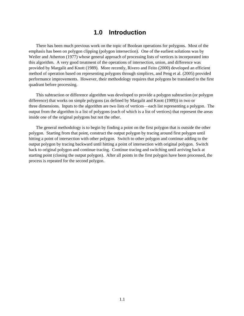
Figure 2.1 depicts an example of polygons to be subtracted. The yellow polygon (denoted as
polygon 2) will be subtracted from the red polygon (denoted as polygon 1). There will be six resulting
polygons—three red and three yellow. None of the overlapping orange area will be in the output.
2.2
Figure 2.1. Input Polygons to be Subtracted
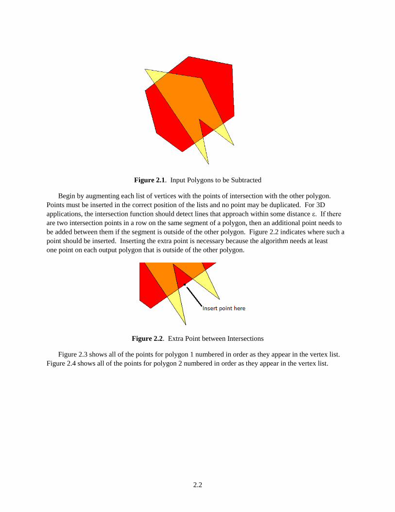
Begin by augmenting each list of vertices with the points of intersection with the other polygon.
Points must be inserted in the correct position of the lists and no point may be duplicated. For 3D
applications, the intersection function should detect lines that approach within some distance ε. If there
are two intersection points in a row on the same segment of a polygon, then an additional point needs to
be added between them if the segment is outside of the other polygon. Figure 2.2 indicates where such a
point should be inserted. Inserting the extra point is necessary because the algorithm needs at least
one point on each output polygon that is outside of the other polygon.
Figure 2.2. Extra Point between Intersections
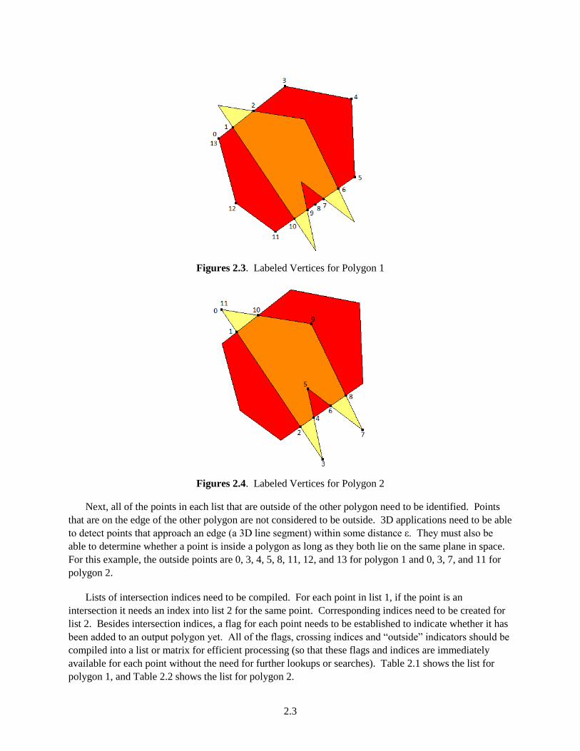
Figure 2.3 shows all of the points for polygon 1 numbered in order as they appear in the vertex list.
Figure 2.4 shows all of the points for polygon 2 numbered in order as they appear in the vertex list.
2.3
Figures 2.3. Labeled Vertices for Polygon 1
Figures 2.4. Labeled Vertices for Polygon 2
Next, all of the points in each list that are outside of the other polygon need to be identified. Points
that are on the edge of the other polygon are not considered to be outside. 3D applications need to be able
to detect points that approach an edge (a 3D line segment) within some distance ε. They must also be
able to determine whether a point is inside a polygon as long as they both lie on the same plane in space.
For this example, the outside points are 0, 3, 4, 5, 8, 11, 12, and 13 for polygon 1 and 0, 3, 7, and 11 for
polygon 2.
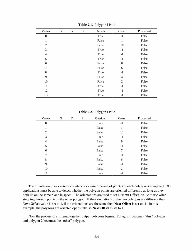
Lists of intersection indices need to be compiled. For each point in list 1, if the point is an
intersection it needs an index into list 2 for the same point. Corresponding indices need to be created for
list 2. Besides intersection indices, a flag for each point needs to be established to indicate whether it has
been added to an output polygon yet. All of the flags, crossing indices and “outside” indicators should be
compiled into a list or matrix for efficient processing (so that these flags and indices are immediately
available for each point without the need for further lookups or searches). Table 2.1 shows the list for
polygon 1, and Table 2.2 shows the list for polygon 2.
2.4
Table 2.1. Polygon List 1
Vertex X Y Z Outside Cross Processed
0 True -1 False
1 False 1 False
2 False 10 False
3 True -1 False
4 True -1 False
5 True -1 False
6 False 8 False
7 False 6 False
8 True -1 False
9 False 4 False
10 False 2 False
11 True -1 False
12 True -1 False
13 True -1 False
Table 2.2. Polygon List 2
Vertex X Y Z Outside Cross Processed
0 True -1 False
1 False 1 False
2 False 10 False
3 True -1 False
4 False 9 False
5 False -1 False
6 False 7 False
7 True -1 False
8 False 6 False
9 False -1 False
10 False 2 False
11 True -1 False
The orientation (clockwise or counter-clockwise ordering of points) of each polygon is computed. 3D
applications must be able to detect whether the polygon points are oriented differently as long as they
both lie on the same plane in space. The orientations are used to set a “Next Offset” value to use when
stepping through points in the other polygon. If the orientations of the two polygons are different then
Next Offset value is set to 1, if the orientations are the same then Next Offset is set to -1. In this
example, the polygons are oriented oppositely, so Next Offset is set to 1.
Now the process of stringing together output polygons begins. Polygon 1 becomes “this” polygon
and polygon 2 becomes the “other” polygon.
2.5
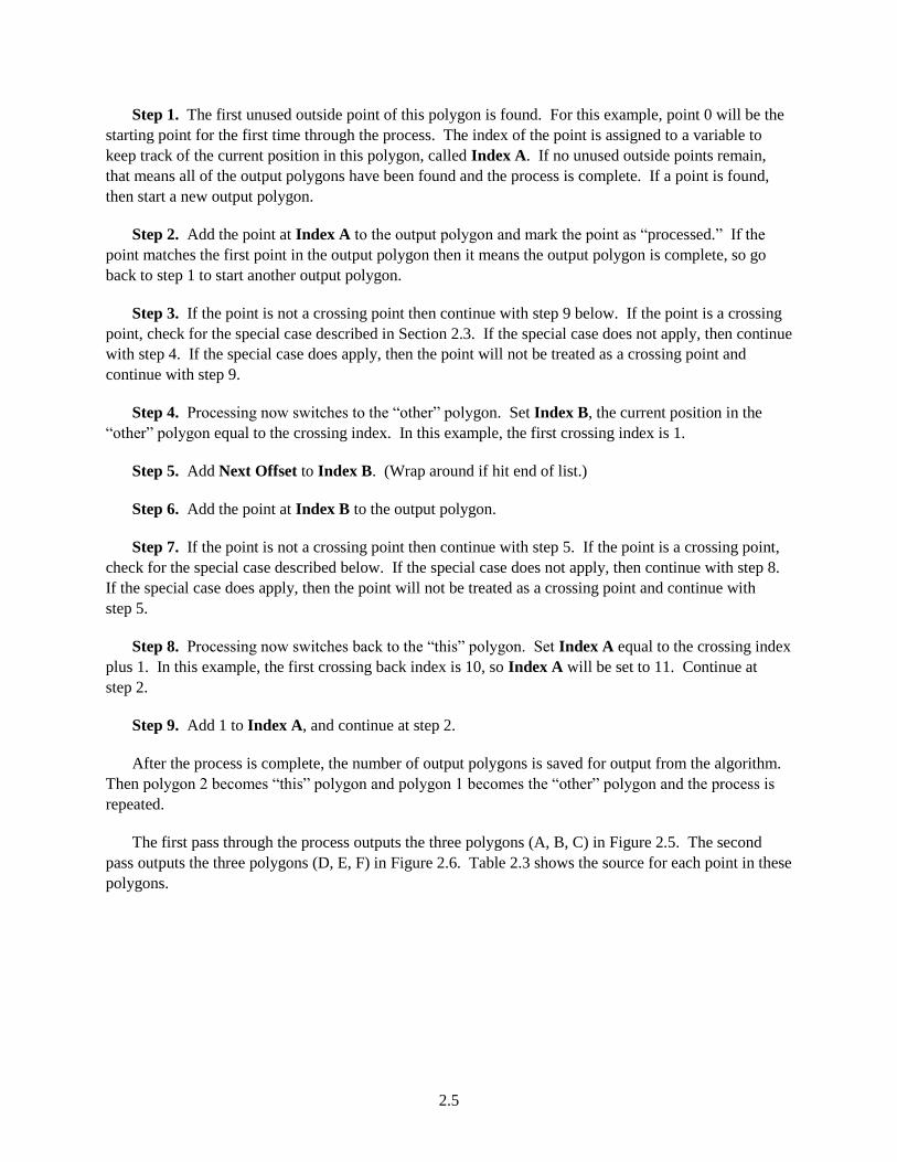
Step 1. The first unused outside point of this polygon is found. For this example, point 0 will be the
starting point for the first time through the process. The index of the point is assigned to a variable to
keep track of the current position in this polygon, called Index A. If no unused outside points remain,
that means all of the output polygons have been found and the process is complete. If a point is found,
then start a new output polygon.
Step 2. Add the point at Index A to the output polygon and mark the point as “processed.” If the
point matches the first point in the output polygon then it means the output polygon is complete, so go
back to step 1 to start another output polygon.
Step 3. If the point is not a crossing point then continue with step 9 below. If the point is a crossing
point, check for the special case described in Section 2.3. If the special case does not apply, then continue
with step 4. If the special case does apply, then the point will not be treated as a crossing point and
continue with step 9.
Step 4. Processing now switches to the “other” polygon. Set Index B, the current position in the
“other” polygon equal to the crossing index. In this example, the first crossing index is 1.
Step 5. Add Next Offset to Index B. (Wrap around if hit end of list.)
Step 6. Add the point at Index B to the output polygon.
Step 7. If the point is not a crossing point then continue with step 5. If the point is a crossing point,
check for the special case described below. If the special case does not apply, then continue with step 8.
If the special case does apply, then the point will not be treated as a crossing point and continue with
step 5.
Step 8. Processing now switches back to the “this” polygon. Set Index A equal to the crossing index
plus 1. In this example, the first crossing back index is 10, so Index A will be set to 11. Continue at
step 2.
Step 9. Add 1 to Index A, and continue at step 2.
After the process is complete, the number of output polygons is saved for output from the algorithm.
Then polygon 2 becomes “this” polygon and polygon 1 becomes the “other” polygon and the process is
repeated.
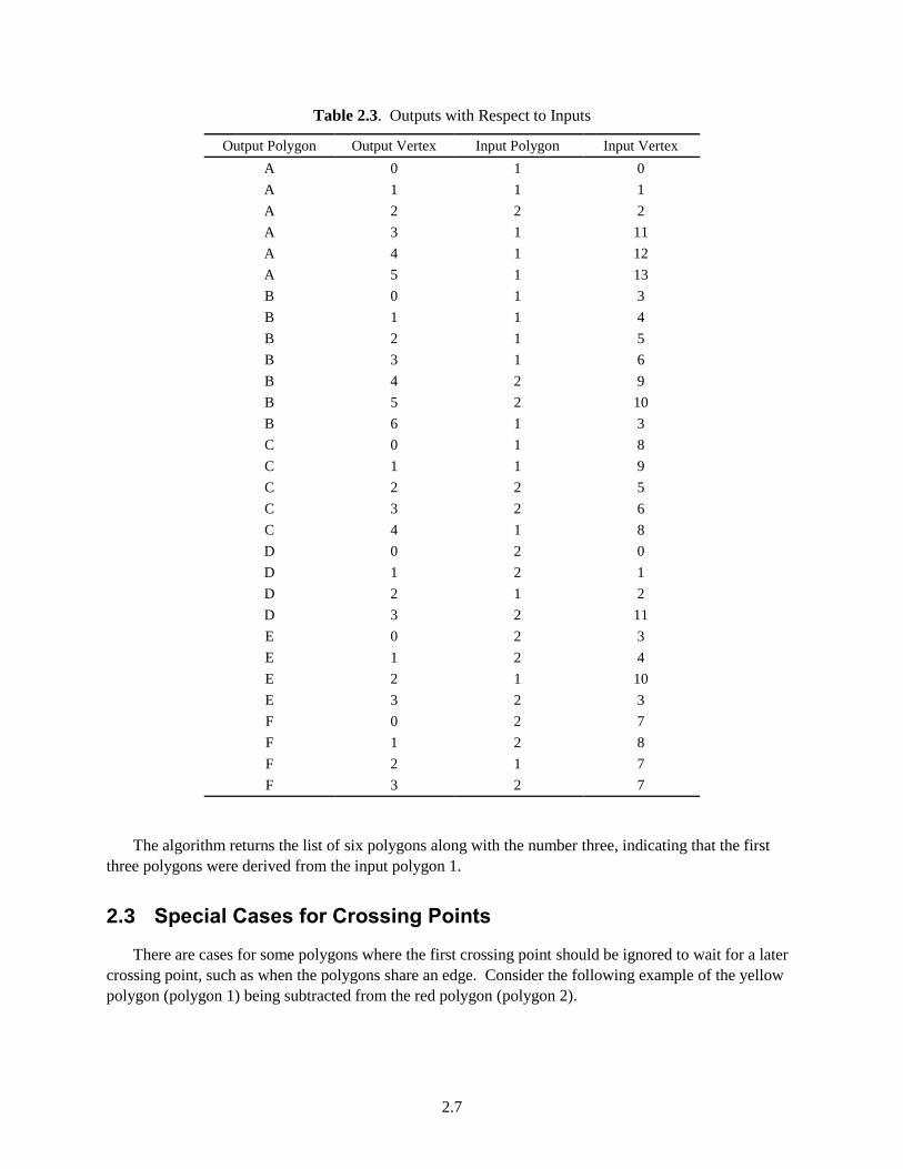
The first pass through the process outputs the three polygons (A, B, C) in Figure 2.5. The second
pass outputs the three polygons (D, E, F) in Figure 2.6. Table 2.3 shows the source for each point in these
polygons.

2.6
Figure 2.5. Output from First Pass
Figure 2.6. Output from Second Pass
2.7
Table 2.3. Outputs with Respect to Inputs
Output Polygon Output Vertex Input Polygon Input Vertex
A 0 1 0
A 1 1 1
A 2 2 2
A 3 1 11
A 4 1 12
A 5 1 13
B 0 1 3
B 1 1 4
B 2 1 5
B 3 1 6
B 4 2 9
B 5 2 10
B 6 1 3
C 0 1 8
C 1 1 9
C 2 2 5
C 3 2 6
C 4 1 8
D 0 2 0
D 1 2 1
D 2 1 2
D 3 2 11
E 0 2 3
E 1 2 4
E 2 1 10
E 3 2 3
F 0 2 7
F 1 2 8
F 2 1 7
F 3 2 7
The algorithm returns the list of six polygons along with the number three, indicating that the first
three polygons were derived from the input polygon 1.
2.3 Special Cases for Crossing Points
There are cases for some polygons where the first crossing point should be ignored to wait for a later
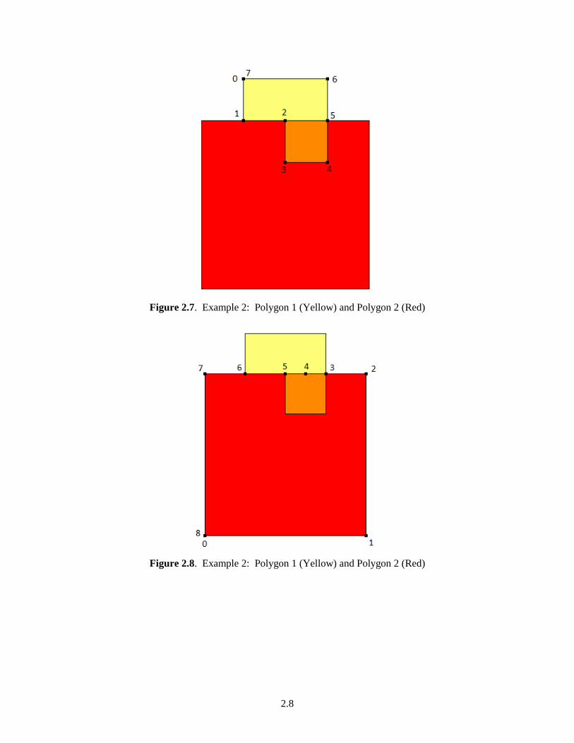
crossing point, such as when the polygons share an edge. Consider the following example of the yellow
polygon (polygon 1) being subtracted from the red polygon (polygon 2).
2.8
Figure 2.7. Example 2: Polygon 1 (Yellow) and Polygon 2 (Red)
Figure 2.8. Example 2: Polygon 1 (Yellow) and Polygon 2 (Red)

2.9
Table 2.4. Crossings and Outside Flags for Example 2
Polygon 1 (Yellow) Polygon 2 (Red)
Vertex Outside Cross Vertex Outside Cross
0 True -1 0 True -1
1 False 6 1 True -1
2 False 5 2 True -1
3 False -1 3 False 5
4 False -1 4 False -1
5 False 3 5 False 2
6 True -1 6 False 1
7 True -1 7 True -1
8 True -1
As the first output polygon is being compiled, vertex 0 and then vertex 1 are output. Since vertex 1 is
a crossing point, we would normally cross over to vertex 6 of the red polygon. However, by looking
ahead we see that if we did, the next point would immediately cross back to point 2 of the yellow
polygon. That would lead to incorrect results. So, a series of rules need to be applied before accepting a
cross-over point:
Rule 1: Check the Outside status of the vertex on the other polygon after the crossing. If it is
outside, then don’t cross at this point. If it is not outside, then apply rule 2. (If traversing the “other”
polygon the rule needs to be reversed: if the vertex on “this” polygon after the crossing is not outside,
then don’t cross at this point.)
Rule 2: Check the Cross status of the vertex on the other polygon after the crossing. If it is not a
crossing, go ahead and accept the first crossing. If it is a crossing, then the Cross status becomes the
“Crossback” and rule 3 is applied.
Rule 3: If the “Crossback” is equal to the “Next” point on this polygon, then don’t cross at this
point. Otherwise, go ahead and accept the crossing.
To apply rule 1 to vertex 1: the point after the crossing is point 5 on the red polygon. It is not
outside, so there is no need to reject the crossing at this point. Rule 2 needs to be applied.
To apply rule 2: point 5 on the red polygon is a crossing point. Therefore, rule 3 needs to be applied.
The Crossback is vertex 2.
To apply rule 3: the Crossback is vertex 2 (on the yellow polygon). The Next vertex on this (the
yellow) polygon is also 2. Since the Crossback matches the Next point, reject the crossing. Move on to
vertex 2 of the yellow polygon and output it. It is also a crossing point, but will be accepted by rule 2.
After the first polygon is output, the next output polygon is compiled using polygon 2 (the red
polygon) as “this” polygon and polygon 1 (the yellow polygon) as the “other” polygon. Vertices 0, 1, 2,
and 3 are output from red polygon followed by vertices 4, 3, and 2 from the yellow polygon. Vertex 2 is
a crossing point. The crossing is vertex 5 of the red polygon. When applying rule 1 (the reverse part) to
2.10
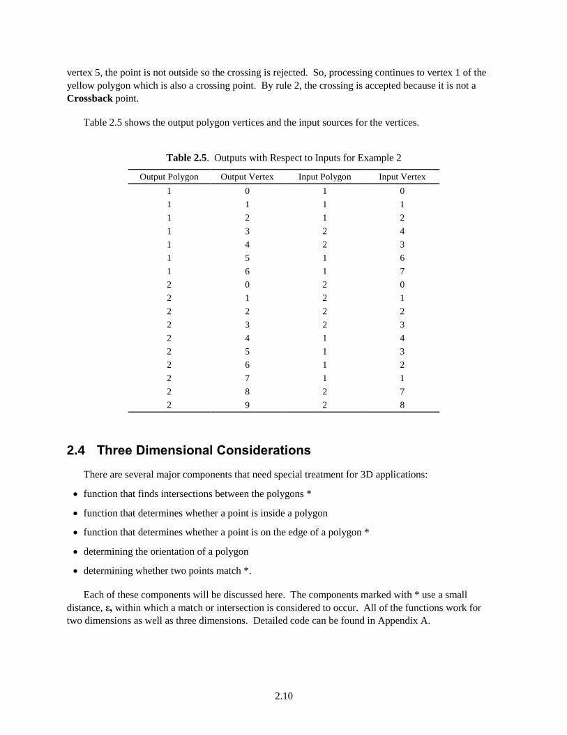
vertex 5, the point is not outside so the crossing is rejected. So, processing continues to vertex 1 of the
yellow polygon which is also a crossing point. By rule 2, the crossing is accepted because it is not a
Crossback point.
Table 2.5 shows the output polygon vertices and the input sources for the vertices.
Table 2.5. Outputs with Respect to Inputs for Example 2
Output Polygon Output Vertex Input Polygon Input Vertex
1 0 1 0
1 1 1 1
1 2 1 2
1 3 2 4
1 4 2 3
1 5 1 6
1 6 1 7
2 0 2 0
2 1 2 1
2 2 2 2
2 3 2 3
2 4 1 4
2 5 1 3
2 6 1 2
2 7 1 1
2 8 2 7
2 9 2 8
2.4 Three Dimensional Considerations
There are several major components that need special treatment for 3D applications:
function that finds intersections between the polygons *
function that determines whether a point is inside a polygon
function that determines whether a point is on the edge of a polygon *
determining the orientation of a polygon
determining whether two points match *.
Each of these components will be discussed here. The components marked with * use a small
distance, ε, within which a match or intersection is considered to occur. All of the functions work for
two dimensions as well as three dimensions. Detailed code can be found in Appendix A.

2.11
2.4.1 Finding Intersections
Each segment of one polygon needs to be compared to each segment of the other polygon. There are
three comparisons between the two segments. Name the ends of the first segment point 1 and point 2.
Name the ends of the second segment point 3 and point 4.
if the distance from point 1 to the second segment is less than ε, then point 1 is an intersection
if the distance from point 2 to the second segment is less than ε, then point 2 is an intersection
if the line segments approach within ε of each other, the closest approach point is an intersection.
Duplicate intersections should be eliminated. The intersections should be added to the vertex list
ordered by their distance from the first point so they appear in the proper order.
2.4.2 Determining Whether a Point is Inside of a Polygon
A sum of angles from the point to each segment of the polygon is used to determine whether the point
is inside. If the sum is approximately -2PI or +2PI radians, then the point is inside. The angle to each
segment is based on the formula:
Cosine(theta) = DotProduct(V1,V2) / (Length(V1) * Length(V2))
where:
V1 is the vector from the point to one end of the segment
V2 is the vector from the point to the other end of the segment
The normal of each angle segment is compared to the normal of the first angle segment. If the
normals are different, then the angle is negated before being added to the sum. The normal is computed
as:
Normal = CrossProduct(V1,V2) normalized to unit length
where:
V1 is the vector from the point to one end of the segment
V2 is the vector from the point to the other end of the segment
2.4.3 Determining Whether a Point is on the Edge of a Polygon
The point is checked against each segment of the polygon. If the closest approach distance between
the point and a line segment in three dimensions is less than ε, then the point is considered to be on the
edge of the polygon.
2.12
2.4.4 Determining the Orientation of a Polygon
A normal is used to define the orientation of a polygon in three dimensions. Three consecutive, non-
linear vertices are found on the polygon and are labeled P1, C, P2 (C denotes the “corner”). The normal
is the cross product of the two vectors C→P1 and C→P2 set to unit length (a distance of one from the
origin of 0,0,0). The normal is represented by a point in three dimensions.
If the normals of two polygons are within a distance of ε in three dimensions, then the polygons are
assumed to be oriented the same (facing the same direction).
2.4.5 Determining Whether Two Points Match
If the distance between two points in three dimensions is less than ε, they are assumed to be the same
point (they match). (Though not exact, if all of the coordinate differences are less than ε then the match is
assumed. This is done for computational efficiency.)

3.1
3.0 Conclusions
This algorithm is stable and efficient for polygons in two or three dimensions. When implemented
with indexed lists of flags, the assembly of output points proceeds in linear time. The bulk of processing
is spent in comparing the vertices of each polygon with those of the other polygon in order to determine
intersections. This basically requires 2*n*m comparisons (where n and m are the numbers of vertices of
two polygons) because the first polygon is compared to the second and then the second is compared to the
first. There may be a clever way to reduce the comparisons to n*m by assembling both lists at the same
time, but that is a subject for future research.
4.1
4.0 References
Margalit A and G Knott. 1989. “An algorithm for computing the union, intersection or difference of two
polygons.” Computers & Graphics 13(2):167–183. http://dx.doi.org/10.1016/0097-8493(89)90059-9.
Peng Y, J-H Yong, W-M Dong, H Zhang, and J-G Sun. 2005. “A new algorithm for Boolean operations
on general polygons.” Computers & Graphics 29(1):57–70. http://dx.doi.org/10.1016/j.cag.2004.11.001.
Rivero M and FR Feito. 2000. “Boolean operations on general planar polygons.” Computers &
Graphics 24(6):881–896. http://dx.doi.org/10.1016/S0097-8493(00)00090-X.
Weiler K and P Atherton. 1977. “Hidden surface removal using polygon area sorting.” ACM
SIGGRAPH Computer Graphics 11(2):214–222. http://dx.doi.org/10.1145/965141.563896.

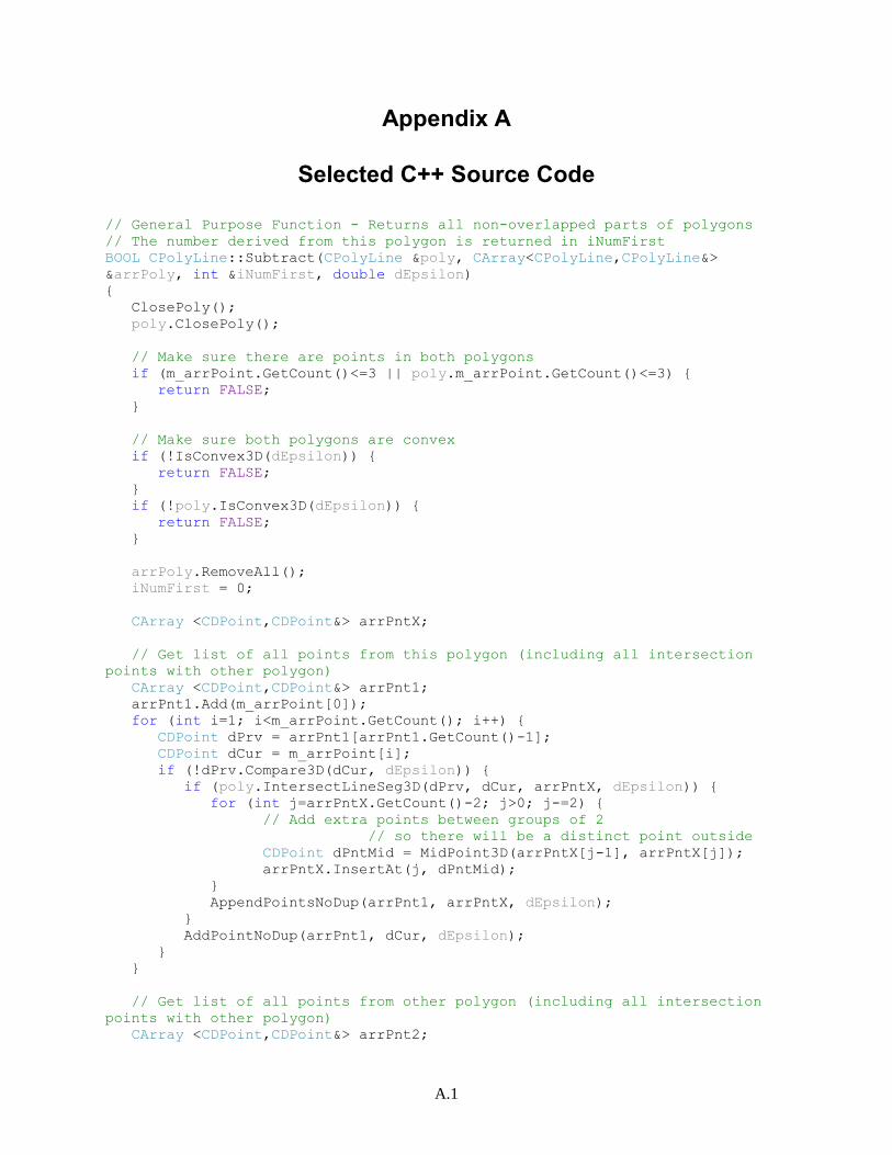
Appendix A
Selected C++ Source Code
A.1
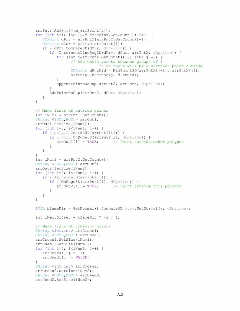
Appendix A
Selected C++ Source Code
// General Purpose Function - Returns all non-overlapped parts of polygons
// The number derived from this polygon is returned in iNumFirst
BOOL CPolyLine::Subtract(CPolyLine &poly, CArray<CPolyLine,CPolyLine&>
&arrPoly, int &iNumFirst, double dEpsilon)
{
ClosePoly();
poly.ClosePoly();
// Make sure there are points in both polygons
if (m_arrPoint.GetCount()<=3 || poly.m_arrPoint.GetCount()<=3) {
return FALSE;
}
// Make sure both polygons are convex
if (!IsConvex3D(dEpsilon)) {
return FALSE;
}
if (!poly.IsConvex3D(dEpsilon)) {
return FALSE;
}
arrPoly.RemoveAll();
iNumFirst = 0;
CArray <CDPoint,CDPoint&> arrPntX;
// Get list of all points from this polygon (including all intersection
points with other polygon)
CArray <CDPoint,CDPoint&> arrPnt1;
arrPnt1.Add(m_arrPoint[0]);
for (int i=1; i<m_arrPoint.GetCount(); i++) {
CDPoint dPrv = arrPnt1[arrPnt1.GetCount()-1];
CDPoint dCur = m_arrPoint[i];
if (!dPrv.Compare3D(dCur, dEpsilon)) {
if (poly.IntersectLineSeg3D(dPrv, dCur, arrPntX, dEpsilon)) {
for (int j=arrPntX.GetCount()-2; j>0; j-=2) {
// Add extra points between groups of 2
// so there will be a distinct point outside
CDPoint dPntMid = MidPoint3D(arrPntX[j-1], arrPntX[j]);
arrPntX.InsertAt(j, dPntMid);
}
AppendPointsNoDup(arrPnt1, arrPntX, dEpsilon);
}
AddPointNoDup(arrPnt1, dCur, dEpsilon);
}
}
// Get list of all points from other polygon (including all intersection
points with other polygon)
CArray <CDPoint,CDPoint&> arrPnt2;
A.2
arrPnt2.Add(poly.m_arrPoint[0]);
for (int i=1; i<poly.m_arrPoint.GetCount(); i++) {
CDPoint dPrv = arrPnt2[arrPnt2.GetCount()-1];
CDPoint dCur = poly.m_arrPoint[i];
if (!dPrv.Compare3D(dCur, dEpsilon)) {
if (IntersectLineSeg3D(dPrv, dCur, arrPntX, dEpsilon)) {
for (int j=arrPntX.GetCount()-2; j>0; j-=2) {
// Add extra points between groups of 2
// so there will be a distinct point outside
CDPoint dPntMid = MidPoint3D(arrPntX[j-1], arrPntX[j]);
arrPntX.InsertAt(j, dPntMid);
}
AppendPointsNoDup(arrPnt2, arrPntX, dEpsilon);
}
AddPointNoDup(arrPnt2, dCur, dEpsilon);
}
}
// Make lists of outside points
int iNum1 = arrPnt1.GetCount();
CArray <BOOL,BOOL> arrOut1;
arrOut1.SetSize(iNum1);
for (int i=0; i<iNum1; i++) {
if (!poly.IsInside3D(arrPnt1[i])) {
if (!poly.OnEdge3D(arrPnt1[i], dEpsilon)) {
arrOut1[i] = TRUE; // Point outside other polygon
}
}
}
int iNum2 = arrPnt2.GetCount();
CArray <BOOL,BOOL> arrOut2;
arrOut2.SetSize(iNum2);
for (int i=0; i<iNum2; i++) {
if (!IsInside3D(arrPnt2[i])) {
if (!OnEdge3D(arrPnt2[i], dEpsilon)) {
arrOut2[i] = TRUE; // Point outside this polygon
}
}
}
BOOL bSameDir = GetNormal().Compare3D(poly.GetNormal(), dEpsilon);
int iNextOffset = bSameDir ? -1 : 1;
// Make lists of crossing points
CArray <int,int> arrCross1;
CArray <BOOL,BOOL> arrUsed1;
arrCross1.SetSize(iNum1);
arrUsed1.SetSize(iNum1);
for (int i=0; i<iNum1; i++) {
arrCross1[i] = -1;
arrUsed1[i] = FALSE;
}
CArray <int,int> arrCross2;
arrCross2.SetSize(iNum2);
CArray <BOOL,BOOL> arrUsed2;
arrUsed2.SetSize(iNum2);
A.3
for (int j=0; j<iNum2; j++) {
arrCross2[j] = -1;
arrUsed2[j] = FALSE;
}
int iNumCross = 0;
for (int i=0; i<iNum1; i++) {
for (int j=0; j<iNum2; j++) {
if (arrPnt1[i].Compare3D(arrPnt2[j], dEpsilon)) {
arrCross1[i] = j;
arrCross2[j] = i;
iNumCross++;
}
}
}
if (iNumCross==0) {
return FALSE;
}
// Extract all the Polygons from List 1
while (TRUE) {
// Find first remaining outside point
CPolyLine newPoly(RGB(0,0,0));
int iCur = -1;
for (int i=0; i<iNum1; i++) {
if (arrOut1[i] && !arrUsed1[i]) {
iCur = i;
break;
}
}
if (iCur < 0) {
// No remaining points outside, we are done
break;
}
while (iCur < iNum1) {
// Emit point
newPoly.AddDPoint(arrPnt1[iCur]);
// Mark so it won't be used again
arrUsed1[iCur] = TRUE;
if (newPoly.m_arrPoint.GetCount()>2 &&
newPoly.m_arrPoint[0].Compare3D(arrPnt1[iCur],
dEpsilon)) {
break; // Polygon wrapped back to beginning point, so stop
and emit polygon
}
// See if Point is a Crossing Point
int iCross = arrCross1[iCur];
if (iCross > -1) {
// Get next point on other polygon after cross
int iNext = StepNext(iCross, iNextOffset, iNum2);
// Make sure it's a cross in
if (arrOut2[iNext]) {
// No, don't cross out

A.4
iCross = -1;
} else {
// Check special case of crossing back to next point
int iCrossBack = arrCross2[iNext];
if (iCrossBack == StepNext(iCur, 1, iNum1)) {
// Just wait for next point
iCross = -1;
}
}
}
if (iCross > -1) {
// Cross over to List 2
int iCur2 = iCross;
while (TRUE) {
// Traverse List 2
iCur2 = StepNext(iCur2, iNextOffset, iNum2);
// Emit point
newPoly.AddDPoint(arrPnt2[iCur2]);
// See if Point is a Crossing Point
iCross = arrCross2[iCur2];
if (iCross > -1) {
// Get next point on polygon1 after cross
int iNext = StepNext(iCross, 1, iNum1);
// Make sure it's a cross out
if (!arrOut1[iNext]) {
// No, don't cross in
iCross = -1;
} else {
// Check special case of crossing back to next
point
int iCrossBack = arrCross1[iNext];
if (iCrossBack == StepNext(iCur2, iNextOffset,
iNum2)){
// Just wait for next point
iCross = -1;
}
}
}
if (iCross > -1) {
// Back to List1
iCur = iCross + 1;
break;
}
}
} else {
// Keep traversing List1
iCur++;
}
}
// Reached end of list, emit the new Polygon
newPoly.SetColor(GetColor());
newPoly.SetExtents();
arrPoly.Add(newPoly);
A.5
iNumFirst++; // Count number of Polygons extracted from this List
1
}
// Extract all the Polygons from List 2
while (TRUE) {
// Find first remaining outside point
CPolyLine newPoly(RGB(0,0,0));
int iCur = -1;
for (int i=0; i<iNum2; i++) {
if (arrOut2[i] && !arrUsed2[i]) {
iCur = i;
break;
}
}
if (iCur < 0) {
// No remaining points outside, we are done
break;
}
while (iCur < iNum2) {
// Emit point
newPoly.AddDPoint(arrPnt2[iCur]);
// Mark so it won't be used again
arrUsed2[iCur] = TRUE;
if (newPoly.m_arrPoint.GetCount()>2 &&
newPoly.m_arrPoint[0].Compare3D(arrPnt2[iCur],
dEpsilon)) {
break; // Polygon wrapped back to beginning point, so stop
and emit polygon
}
// See if Point is a Crossing Point
int iCross = arrCross2[iCur];
if (iCross > -1) {
// Get next point on other polygon after cross
int iNext = StepNext(iCross, iNextOffset, iNum1);
// Make sure it's a cross in
if (arrOut1[iNext]) {
// No, don't cross out
iCross = -1;
} else {
// Check special case of crossing back to next point
int iCrossBack = arrCross1[iNext];
if (iCrossBack == StepNext(iCur, 1, iNum2)) {
// Just wait for next point
iCross = -1;
}
}
}
if (iCross > -1) {
// Cross over to List 1
int iCur2 = iCross;
while (TRUE) {
A.6
// Traverse List 1
iCur2 = StepNext(iCur2, iNextOffset, iNum1);
// Emit point
newPoly.AddDPoint(arrPnt1[iCur2]);
// See if Point is a Crossing Point
iCross = arrCross1[iCur2];
if (iCross > -1) {
// Get next point on polygon2 after cross
int iNext = StepNext(iCross, 1, iNum2);
// Make sure it's a cross out
if (!arrOut2[iNext]) {
// No, don't cross in
iCross = -1;
} else {
// Check special case of crossing back to next
point
int iCrossBack = arrCross2[iNext];
if (iCrossBack == StepNext(iCur2, iNextOffset,
iNum1)){
// Just wait for next point
iCross = -1;
}
}
}
if (iCross > -1) {
// Back to List2
iCur = iCross + 1;
break;
}
}
} else {
// Keep Traversing List2
iCur++;
}
}
// Reached end of list, emit the new Polygon
newPoly.SetColor(poly.GetColor());
newPoly.SetExtents();
arrPoly.Add(newPoly);
}
return TRUE;
}
// See if Polygon touches or crosses itself
// Assumes Polygon is closed
// Returns FALSE if it does
BOOL CPolyLine::IsConvex3D(double dEpsilon)
{
CDPoint dPntX;
int iNumPnt = m_arrPoint.GetCount() - 1;
for (int i=0; i<iNumPnt; i++) {
for (int j=i+1; j<iNumPnt; j++) {
A.7
if (m_arrPoint[i].Compare3D(m_arrPoint[j], dEpsilon)) {
return FALSE;
}
if (i<iNumPnt && j<iNumPnt) {
if (LineLine3D(m_arrPoint[i], m_arrPoint[i+1], m_arrPoint[j],
m_arrPoint[j+1], dPntX, TRUE, dEpsilon)) {
return FALSE;
}
}
}
}
return TRUE;
}
// Determines whether the given line segment intersects the edge of the
polyline in 3D
// All the intersection points are placed into arrPntX
// arrPntX will be sorted based on distance from dPnt1
BOOL CPolyLine::IntersectLineSeg3D(const CDPoint &dPnt1, const CDPoint
&dPnt2, CArray <CDPoint,CDPoint&> &arrPntX, double dEpsilon) const
{
BOOL bIntersect = FALSE;
CArray <CDPoint,CDPoint&> arrTemp;
CDPoint dPntX;
int iPnts = m_arrPoint.GetSize()-1; // Assume closed polygons
for (int i=0; i<iPnts; i++) {
// Check each line segment
int j = (i+1) % iPnts;
CDPoint dPnt3 = m_arrPoint[i];
CDPoint dPnt4 = m_arrPoint[j];
// Does given line segment intersect this line segment?
BOOL bEnds = FALSE;
if (PointLineSegDist3D(dPnt3, dPnt1, dPnt2) <= dEpsilon) {
arrTemp.Add(dPnt3);
bIntersect = TRUE;
bEnds = TRUE;
}
if (PointLineSegDist3D(dPnt4, dPnt1, dPnt2) <= dEpsilon) {
arrTemp.Add(dPnt4);
bIntersect = TRUE;
bEnds = TRUE;
}
if (!bEnds && LineLine3D(dPnt1, dPnt2, dPnt3, dPnt4, dPntX, TRUE,
dEpsilon)) {
arrTemp.Add(dPntX);
bIntersect = TRUE;
}
}
int iNumOut = arrTemp.GetCount();
if (iNumOut > 0) {
// Add intersection point(s) to arrPntX
arrPntX.RemoveAll();
if (iNumOut==1) {
arrPntX.Add(arrTemp[0]); // Just the one
} else {
A.8
// Sort points based on distance from dPnt1
CArray <CDPoint,CDPoint&> arrSort;
arrSort.SetSize(iNumOut);
for (int i=0; i<iNumOut; i++) {
arrSort[i].m_x = i;
arrSort[i].m_y = LineLength3D(dPnt1, arrTemp[i]);
}
qsort(arrSort.GetData(), iNumOut, sizeof(CDPoint), QCompareDPointY);
CDPoint dPntLast = arrTemp[int(arrSort[0].m_x)];
arrPntX.Add(dPntLast);
for (int i=1; i<iNumOut; i++) {
CDPoint dPntThis = arrTemp[int(arrSort[i].m_x)];
if (!dPntThis.Compare3D(dPntLast, dEpsilon)) {
// Filter out duplicate points
arrPntX.Add(dPntThis);
dPntLast = dPntThis;
}
}
}
}
return bIntersect;
}
// Finds the minimum 3D distance from a point to a line segment
double PointLineSegDist3D(const CDPoint &p, const CDPoint &p1, const CDPoint
&p2)
{
double b = (p.m_x-p1.m_x)*(p2.m_x-p1.m_x) + (p.m_y-p1.m_y)*(p2.m_y-p1.m_y)
+ (p.m_z-p1.m_z)*(p2.m_z-p1.m_z);
double dx = (p2.m_x-p1.m_x);
double dy = (p2.m_y-p1.m_y);
double dz = (p2.m_z-p1.m_z);
double c = dx*dx + dy*dy + dz*dz;
if (c == 0.0) {
// Point1 and Point2 are the same
return LineLength(p, p1);
}
double d = b / c;
if (d<0.0 || d>1.0) {
// Closest point to line is not on the segment, so it is one of the end
points
dx = p1.m_x - p.m_x;
dy = p1.m_y - p.m_y;
dz = p1.m_z - p.m_z;
double e = dx*dx + dy*dy + dz*dz;
dx = p2.m_x - p.m_x;
dy = p2.m_y - p.m_y;
dz = p2.m_z - p.m_z;
double f = dx*dx + dy*dy + dz*dz;
if (e<f) {
return sqrt(e);
} else {
return sqrt(f);
}
} else {

A.9
// Closest point to line is on the segment
double d1 = ((p2.m_y-p1.m_y)*(p.m_z-p1.m_z) - (p.m_y-p1.m_y)*(p2.m_z-
p1.m_z));
double d2 = ((p2.m_x-p1.m_x)*(p.m_z-p1.m_z) - (p.m_x-p1.m_x)*(p2.m_z-
p1.m_z));
double d3 = ((p2.m_x-p1.m_x)*(p.m_y-p1.m_y) - (p.m_x-p1.m_x)*(p2.m_y-
p1.m_y));
double a = sqrt( d1*d1 + d2*d2 + d3*d3 );
return a / sqrt(c);
}
}
// Find the point of intersection (pa) between two lines P1:P2 and P3:P4 in
3D.
// Returns FALSE if the lines don't approach within dEpsilon
BOOL LineLine3D(const CDPoint &p1, const CDPoint &p2, const CDPoint &p3,
const CDPoint &p4, CDPoint &pa, BOOL bSegment, double dEpsilon)
{
CDPoint pb; // 2nd perpendicular returned by function below
if (LineLine3D(p1, p2, p3, p4, pa, pb, bSegment, dEpsilon)) {
if (LineLength3D(pa, pb) <= dEpsilon) {
// A single point
return TRUE;
}
}
return FALSE;
}
// Finds the line segment Pa:Pb that is the shortest perpendicular between
two lines P1:P2 and P3:P4 in 3D.
// Returns FALSE if two lines (P1:P2 and P3:P4) are parallel
// Also returns FALSE if bSegment is TRUE and either intersection does not
occur within segment
// Based on algorithm by Paul Bourke, University of Western Ausralia,
PaulBourke.net, used with permission - no restrictions
BOOL LineLine3D(const CDPoint &p1, const CDPoint &p2, const CDPoint &p3,
const CDPoint &p4, CDPoint &pa, CDPoint &pb, BOOL bSegment, double dEpsilon)
{
CDPoint p13, p43, p21;
p13.m_x = p1.m_x - p3.m_x;
p13.m_y = p1.m_y - p3.m_y;
p13.m_z = p1.m_z - p3.m_z;
p43.m_x = p4.m_x - p3.m_x;
p43.m_y = p4.m_y - p3.m_y;
p43.m_z = p4.m_z - p3.m_z;
if (fabs(p43.m_x) <= dEpsilon && fabs(p43.m_y) <= dEpsilon &&
fabs(p43.m_z) <= dEpsilon) {
return FALSE;
}
p21.m_x = p2.m_x - p1.m_x;
p21.m_y = p2.m_y - p1.m_y;
p21.m_z = p2.m_z - p1.m_z;
A.10
if (fabs(p21.m_x) <= dEpsilon && fabs(p21.m_y) <= dEpsilon &&
fabs(p21.m_z) <= dEpsilon) {
return FALSE;
}
double d1343, d4321, d1321, d4343, d2121;
d1343 = p13.m_x * p43.m_x + p13.m_y * p43.m_y + p13.m_z * p43.m_z;
d4321 = p43.m_x * p21.m_x + p43.m_y * p21.m_y + p43.m_z * p21.m_z;
d1321 = p13.m_x * p21.m_x + p13.m_y * p21.m_y + p13.m_z * p21.m_z;
d4343 = p43.m_x * p43.m_x + p43.m_y * p43.m_y + p43.m_z * p43.m_z;
d2121 = p21.m_x * p21.m_x + p21.m_y * p21.m_y + p21.m_z * p21.m_z;
double denom = d2121 * d4343 - d4321 * d4321;
if (fabs(denom) <= dEpsilon) {
return(FALSE);
}
double numer = d1343 * d4321 - d1321 * d4343;
double mua = numer / denom; // Where Pa = P1 + mua (P2 - P1)
double mub = (d1343 + d4321 * (mua)) / d4343; // Where Pb = P3
+ mub (P4 - P3)
if (bSegment) {
if (mua<=0.0 || mua>=1.0) {
// Don't intersect within line segments
return FALSE;
}
if (mub<=0.0 || mub>=1.0) {
// Don't intersect within line segments
return FALSE;
}
}
pa.m_x = p1.m_x + mua * p21.m_x;
pa.m_y = p1.m_y + mua * p21.m_y;
pa.m_z = p1.m_z + mua * p21.m_z;
pb.m_x = p3.m_x + mub * p43.m_x;
pb.m_y = p3.m_y + mub * p43.m_y;
pb.m_z = p3.m_z + mub * p43.m_z;
return TRUE;
}
double LineLength3D(const CDPoint &pnt1, const CDPoint &pnt2)
{
double dX = pnt1.m_x - pnt2.m_x;
dX *= dX;
double dY = pnt1.m_y - pnt2.m_y;
dY *= dY;
double dZ = pnt1.m_z - pnt2.m_z;
dZ *= dZ;
A.11
return sqrt(dX + dY + dZ);
}
// Returns TRUE if point on edge of PolyLine
BOOL CPolyLine::OnEdge3D(const CDPoint &dPnt, double dEpsilon)
{
int iNumPoints = m_arrPoint.GetCount();
if (iNumPoints>1) {
for (int i=0; i<iNumPoints; i++) {
int j = (i+1)%iNumPoints;
if (!m_arrPoint[i].Compare3D(m_arrPoint[j], dEpsilon)) { // Skip
segments of duplicate point
if (PointLineSegDist3D(dPnt, m_arrPoint[i], m_arrPoint[j]) <=
dEpsilon) {
return TRUE;
}
}
}
}
return FALSE;
}
// See if point is inside polygon in 3D space
BOOL CPolyLine::IsInside3D(const CDPoint &dPnt) const
{
int nPnts = m_arrPoint.GetSize();
if (nPnts>2) {
double dSumTheta = 0.0;
CDPoint dNormal = CalcNormal(dPnt, m_arrPoint[0], m_arrPoint[1]);
for (int i=0; i<nPnts; i++) {
// Get the angle to the 2 points that make up the segment
int j = (i+1)%nPnts;
double dTheta = CalcAngle3D(dPnt, m_arrPoint[i], m_arrPoint[j]);
CDPoint dNormalTest = CalcNormal(dPnt, m_arrPoint[i],
m_arrPoint[j]);
if (!dNormal.Compare3D(dNormalTest,0.000001)) {
dTheta = -dTheta;
}
// Sum of all angles
dSumTheta += dTheta;
}
if (fabs(dSumTheta - 2.0*PI) < 0.000001) {
// If sum approaches 2PI, it is inside
return TRUE;
}
if (fabs(dSumTheta + 2.0*PI) < 0.000001) {
// If sum approaches -2PI, it is inside
return TRUE;
}
}
return FALSE;
}
CDPoint CalcNormal(CDPoint dCorner, CDPoint dPnt1, CDPoint dPnt2)
{
// Cross product of 2 vectors to get normal
A.12
CDPoint N;
N.m_x = (dPnt1.m_y-dCorner.m_y)*(dPnt2.m_z-dCorner.m_z) - (dPnt1.m_z-
dCorner.m_z)*(dPnt2.m_y-dCorner.m_y);
N.m_y = (dPnt1.m_z-dCorner.m_z)*(dPnt2.m_x-dCorner.m_x) - (dPnt1.m_x-
dCorner.m_x)*(dPnt2.m_z-dCorner.m_z);
N.m_z = (dPnt1.m_x-dCorner.m_x)*(dPnt2.m_y-dCorner.m_y) - (dPnt1.m_y-
dCorner.m_y)*(dPnt2.m_x-dCorner.m_x);
// Find length of normal vector
double dLength = sqrt(N.m_x*N.m_x + N.m_y*N.m_y + N.m_z*N.m_z);
// Normalize (make it unit length)
N.m_x /= dLength;
N.m_y /= dLength;
N.m_z /= dLength;
return N;
}
// Calculates the Angle in 3D
// P0 ---------P1
// \
// \ Angle
// \
// \
// P2
double CalcAngle3D(const CDPoint &dPnt0, const CDPoint &dPnt1, const CDPoint
&dPnt2)
{
// Based on formula Cosine(theta) = DotProduct(V1,V2) / (Length(V1) *
Length(V2))
double dDotProduct = (dPnt1.m_x-dPnt0.m_x)*(dPnt2.m_x-dPnt0.m_x) +
(dPnt1.m_y-dPnt0.m_y)*(dPnt2.m_y-dPnt0.m_y) +
(dPnt1.m_z-dPnt0.m_z)*(dPnt2.m_z-dPnt0.m_z);
double dCosTheta = dDotProduct /
(LineLength3D(dPnt0,dPnt1)*LineLength3D(dPnt0,dPnt2));
if (dCosTheta < -1.0) {
dCosTheta = -1.0;
}
if (dCosTheta > 1.0) {
dCosTheta = 1.0;
}
double dTheta = acos(dCosTheta); // Calculate the Angle
return dTheta;
}
// 3D Comparison with tolerance
BOOL CDPoint::Compare3D(const CDPoint &dPnt, double dEps) const
{
if (fabs(m_x - dPnt.m_x) > dEps) {
return FALSE;
}
if (fabs(m_y - dPnt.m_y) > dEps) {
A.13
return FALSE;
}
if (fabs(m_z - dPnt.m_z) > dEps) {
return FALSE;
}
return TRUE;
}