Polyethylene Commercial Tank Sprayers - Cub Cadet · Polyethylene Commercial Tank Sprayers ......
20
Polyethylene Commercial Tank Sprayers Professional Turf Equipment OPERATOR’S MANUAL 50, 100, 200, and 300 Gallon
Transcript of Polyethylene Commercial Tank Sprayers - Cub Cadet · Polyethylene Commercial Tank Sprayers ......

PolyethyleneCommercial Tank Sprayers
Professional Turf Equipment
OPERATOR’S MANUAL
50, 100, 200, and 300 Gallon

Part No. Polyethylene Tank Sprayers02004702 50 Gallon Electric02004703 100 Gallon Sprayer Package02004704 200 Gallon Sprayer Package02004705 200 Gallon 5.5HP Kawasaki Compact02004706 300 Gallon w5.5HP Kawasaki Engine
TABLE OF CONTENTSForeword........................................................................................................... 3Safety Precautions............................................................................................ 3
A. General .................................................................................................. 3B. Related to Gasoline or Engines ............................................................. 3C. Related to Batteries ............................................................................... 3D. General Requirements-Personal Protective Equipment ........................ 4-5
Specifications.................................................................................................... 6-7Operating Instructions....................................................................................... 8
A. Controls.................................................................................................. 81. Engine Choke...................................................................................... 82. Engine Throttle .................................................................................... 83. Ignition Switch ..................................................................................... 84. Rewind Pull-Cord Starter..................................................................... 85. Valves.................................................................................................. 86. Pressure Gauge .................................................................................. 87. Pressure Regulator ............................................................................. 8-9
B. Set up..................................................................................................... 91. General................................................................................................ 92. Installation in a Van or Pickup Truck ................................................... 93. Wiring .................................................................................................. 9-10
C. Spraying................................................................................................. 101. Starting the Sprayer - Gasoline-Powered............................................ 102. Starting the Sprayer - Electric-Powered .............................................. 10-113. Calibration ........................................................................................... 11-12
a. Hand Spraying .............................................................................. 11b. Boom Spraying ............................................................................. 12
3. Tips on Spraying ................................................................................. 13-15a. Mixing Dry-Bagged Products for Sprayer Use.............................. 13b. Use of the Gun.............................................................................. 13c. Use of the Spray Wand................................................................. 14d. Use of High Pressure Guns .......................................................... 14-15
4. Cleaning the Sprayer........................................................................... 15Maintenance Instructions.................................................................................. 15-17A. Engine Maintenance Schedule..................................................................... 15
B. Battery.................................................................................................... 15C. Pump...................................................................................................... 15-16D. Agitator................................................................................................... 16E. Tank ....................................................................................................... 16F. In-Line Strainer....................................................................................... 16G. Hose ...................................................................................................... 16H. Storage and Winterizing......................................................................... 16-17
Troubleshooting Guide ..................................................................................... 17
Patent Pending
2

FOREWORDThe Cub Cadet Commercial line of sprayers is designed to provide professional turfgrass managers with reliable spray equipment. The line includes both polyethylene and fiberglass tank sprayers. They are either gasoline or electric powered and range in maximum output from 4.8 GPM to 14 GPM. This manual presents the operating and maintenance instructions necessary to keep your Cub Cadet Commercial Sprayer at peak efficiency. If properly operated and maintained, your Cub Cadet Commercial Sprayer will provide dependable service.
NOTE: The engine manufacturer is responsible for all engine-related issues with regards to performance, power-rating, specifications, warranty and service. Please refer to the engine manufacturer’s owner’s/operator’s manual, packed seperately with your unit, for more information.
SAFETY PRECAUTIONS
A. General1. No one should operate or maintain this sprayer who has not read this manual.
2. Keep adults, children and pets away from the sprayer and the area to be sprayed.
3. If truck or trailer mounted, make certain the sprayer is securely bolted to the frame of the truck or trailer.
4. When spraying pesticides:a.ALWAYS FOLLOW THE DIRECTIONS ON
THE LABELb.Avoid breathing vapors.c.Avoid contact with skin, eyes or clothing.d.Wear rubber boots or rubberized shoes.e.Wear work clothes with long-sleeved shirts
and long-legged pants.f.Change to clean clothing daily.g.Wash hands and face before eating or
smoking.h.Bathe thoroughly as soon after spraying as
possible.5. Wear a face shield and rubber gloves when
handling concentrates.6. Do not remove any shields, guards or safety
devices from the sprayer. If a shield, guard or safety device is damaged or does not function, repair or replace it before operating the sprayer.
B. Related to Gasoline or Engines1. GASOLINE IS HIGHLY FLAMMABLE
RESPECT IT!2. Do not smoke or permit others to smoke while
handling gasoline.3. Always use approved containers for gasoline.4. Always shut off a gasoline engine and permit it
3
to cool before removing the cap of the fuel tank.5. Always fill the fuel tank outdoors.6. If the fuel container spout will not fit INSIDE the
fuel tank opening, use a funnel.7. When filling the fuel tank, stop when the
gasoline reaches 1/2 inch from the top. This space must be left for expansion. DO NOT OVERFILL!
8. Wipe up any spilled gasoline.9. To prevent hand or arm injury, always pull
engine starter cord rapidly to avoid kickback.10. Never run a gasoline engine indoors without
adequate ventilation. Exhaust fumes are deadly.
11.To avoid serious burns, do not touch a gasoline engine, the exhaust pipe or muffler while the engine is running or until it has cooled after it has been shut off.
12.Do not operate or store the machine or fuel container inside where there is an open flame, spark or pilot light such as a water heater, furnace, clothes dryer, etc.
C. Related to Batteries1. The electrolyte in a lead-acid battery is
dilute sulfuric acid which is a very dangerous and corrosive liquid. Always wear safety glasses or goggles and rubber gloves when working on a lead-acid battery.
2. Do not overfill a lead-acid battery when filling the cells with distilled water.
3. Lead-acid batteries generate hydrogen and oxygen gases which form an explosive mixture. Keep sparks and flames away at all times.

D. General Requirements-Personal Protective Equipment
OSHA Standard 1910.132 through 1910.139OSHA standard 1910.132 states in relevant part:
a. Protective equipment, including personal protective equipment (PPE) for eyes, face, head, and extremities, protective clothing, respiratory devices, and protective shields and barriers, shall be provided, used, and maintained in a sanitary and reliable condition whereever it is necessary by reason of hazards of processes or environment, chemical hazards, radiological hazards, or mechanical irritants encountered in a manner capable of causing injury or impairment in the function of any part of the body through absortion, inhalation or physical contact.
This standard is subject to change. Please check www.osha.gov for the latest regulatory updates
GeneralSometimes, it is not possible to reduce a hazard by eliminating it, substituting a less hazardous process or product, making changes to equipment, or even by changing how you do the job. That’s when you need personal protection.PPE includes items like gloves, goggles, boots, hearing protection and respirators. Respirators filter out particles or block gases and vapors that can harm the respiratory system. With a surface area well supplied with blood vessels and equal in size to a tennis court, the lungs are the quickest and most direct route for absorbing harmful substance into your body.
Note: PPE does not prevent accidents, but it does prevent or re-duce injury and even fatalities when used properly.
Equipment (PPE)Protective equipment must be selected carefully. Always test fit the protective equipment to be sure it fits properly and comfort-ably. If it isn’t comfortable -- it won’t be worn; if it isn’t worn -- it won’t protect. PPE includes:
• respirators• chemical-resistant clothing• hearing protectors• gloves• safety goggles and glasses• hard hats• sensors to detect hazardous substance• communication devices used for safe
deployment of workers
Inhaling pesticide fumes and mists is a very common entry route of pesticides into the body. Absortion through the lungs is great and the sensitivity is high.
The National Institute for Occupational Safety and Health (NIOSH), under authority of the Federal Mine Safety and Health
4
Act of 1977 and the Occupational Safety and Health Act of 1970, tests, approves, and certifies respiratory equipment as being safe for its intended purpose.
Note: Always be certain that the NIOSH compliance number is on the product before purchasing respiratory equipment.
Two systems of respiratory protection are available, depending on the type of respiratory risk involved: air-purification (filtering) and air-supplying. For most pesticide work, the air-purifying equipment is adequate and safe.
Protective equipment is usually required by the pesticide label in one form or another and is integral to safe pesticide application. Chemical-protective clothing consists of multilayered garments made out of various materials that protect against a variety of haz-ards. Because no single material can protect against all chemicals, multiple layers of various materials usually are used to increase the degree of protection. Protection is maximized by total encap-sulation (completely covering the wearer). An assortment of types of chemical-protective hats, hoods, gloves, and boot covers are used with the garments.
There are many brands and models of protective equipment avail-able for use in pesticide application. Price is not always an indi-cator of quality, so shop carefully.
Note: Select equipment that is NIOSH tested and approved.
Protective equipment, appropriate for the task and hazards that an employee could be exposed, shall be provided by the employer. Since comfort and proper fit must be considered, the person who is going to use it must select the proper size to ensure correct fit and function. Unused protective equipment does not help anyone.
Note: Many supply centers, hardware stores, chemical retailers, and equipment/machinery dealers keep protective equipment in stock.
TrainingWritten procedures shall be developed for PPE use. These proce-dures shall include all information and guidance necessary for their proper selection, use and care. The employer shall provide fitting instructions including demonstrations and practice in how the PPE should be worn, It is essential that both supervisors and workers be properly instructed in PPE selection, use, and mainte-nance. Training shall provide the workers an opportunity to handle PPE, and have it fitted properly.
When to replace PPEAll PPE shall be inspected routinely before and after each use. A program for maintenance and care of PPE shall be initiated and be adjusted to the type of work place, working conditions, and haz-ards. It shall include the following:
• inspection for defects and damage• cleaning and disinfecting• repair• storage
Many factors influence how long PPE (especially respirators) re-mains effective. As well as hours of use, an air-purifying respira-

tor’s service life is affected by the concentration of dust and other contaminants in the enviroment; the user’s body size; how stren-uously the user works while the respirator is worn; and how the respirator is stored.
Note: As a result, it’s not possible to specify a length of time after which a respirator should be replaced.
In general, replace a mask or filter when it is visibly dirty or dam-aged, or when you experience difficulty breathing through it. Re-place respirator cartridges when you can smell or taste chemical while or after using the respirator, or according to the manufactur-er’s recommendations. Replacement or repairs shall be done only by experienced person with parts designed for the PPE. No at-tempts shall be made to replace components or to make adjust-ments or repairs beyond the manufacturer’s recommendations.
5

SPECIFICATIONS
TANKSPolyethylene: Sturdy, rotationally molded, rectangular shaped, polyethylene tanks in 50, 100, 200 or 300 gallon capacities. The 200 gallon tank has a 10 inch fillwell. The fillwell is equipped with a strainer basket and a screw-on, leak proof lid. The 50, 100 and 300 gallon tanks have 10 inch fillwells equipped with strainer baskets and splash-guard covers. All of the tanks have gallonage markers molded into the plastic.FRAMESPolyethylene: 50 gallon frames are constructed of eleven gauge steel. 100, 200 and 300 gallon frames are constructed of ten gauge steel while engine and pump bases are formed into channels from seven gauge steel and then electric-welded to the frames to form a rigid, unitized assembly. All frames have punched holes to accept optional accessories.
ENGINES/PUMPSElectric - 12-Volt permanent magnet motor driven four-diaphragm pump, 4.8 GPM at 40 psi.Gas-Powered Polyethylene
50 Gallon: 4.0-HP Kawasaki, 4-cycle, air-cooled, recoil-start engine which is directly coupled through a gear reduction to a twin-diaphragm pump (6.0-GPM max. or 275-psi max.) 100, 200 and 300 gallon: 5.5-HP Kawasaki, 4-cycle, air-cooled, recoil-start, engine which drives a twin-diaphragm pump (9.5-GPM max. or 550-psi max.) through a gear reduction.200 gallon compact: 5.5-HP Kawasaki air cooled engine drives a triple-diaphragm pump through a gear reduction.
IN-LINE STRAINERAll sprayers have a suction strainer with a 30-mesh stainless steel screen located on the inlet side of the pump.
AGITATIONPolyethylene
Electric & 50 Gallon: Bypass, triple-jet agitation. 100, 200 and 300 Gallon: Pressurized, triple-jet agitation.
PRESSURE REGULATOR(Gas-powered only)
Adjustable pressure regulating valve with a glycerine-dampened pressure gauge (0-860 psi).
6
NET WEIGHT (Without reel or hose.)Polyethylene
50 Gallon: 125 lbs.100 Gallon: 237 lbs.200 Gallon: 336 lbs.300 Gallon: 422 lbs.
DIMENSIONSPolyethylene50 Gallon:Length: 53 1/2" (Includes 6 inch bumper.)Tank Width: 19 inchesFrame Width: 19 inches, 21 1/4" with hose reelHeight: 26 inches, 43" with hose reel100 Gallon:Length: 48 inches, 49" to drain capTank Width: 30 inchesFrame Width: 38 inchesHeight (to top of tank): 34 inches, 42" w/hose reel200 Gallon:
Length: 65 inches, 66" to drain capTank Width: 39 inchesFrame Width: 38 inchesHeight (to top of tank): 40 Inches, 42" w/hose reel
300 Gallon:Length: 88 Inches, 89" to drain capTank Width: 38 inchesFrame Width: 38 inchesHeight (to top of tank): 47 inches

SPECIFICATIONS
OPTIONS AVAILABLE• High pressure hoses
Walking BoomTwo-Wheeled, Stainless Steel Hand Spray Boom, 8- 8008 SS Quick Change Nozzles on 1O'' centers. Includes 10" x 1.75 semi-pneumatic rubber wheels, 200 psi gauge and trigger-grip shutoff valve. Nozzle spacing, boom spray height and handle are adjustable.
ReelsManual: These reels are typically used for short hoses , or when smaller I.D. hoses are specified.Power: These 12 VDC powered reels are particularly useful when large I.D. and long hoses are specified.Mounting: Manual and lower reels are normally attached to supports which are bolted to the sprayer frame. Most of the reel supports allow the reels to be mounted along axis orientations parallel or perpendicular to the sprayer tank. Additionally, some reel supports (such as the 50 gallon) can be reversed so that the reel is over the tank rather than the engine.
AccessoriesThere are numerous accessories including Vertical and horizontal hose guides. Hoses with larger and smaller I.D.s as well as shorter and longer lengths are available.
7
OPERATING INSTRUCTIONS
A.CONTROLS1. Engine ChokeThere are usually two moving levers on the side of an engine near the carburetor. One of these is the choke, the other is the throttle. The choke lever should be moved all the way to the "CHOKE" position when starting a cold engine. After the engine starts, slowly move the lever all the way back to the "RUN" position as the engine warms up. A warm engine should not be choked.
2. Engine ThrottleThe second moving lever on the side of an engine near the carburetor is the throttle. For starting, place the lever at 50% of the maximum RPM. For pump pressures up to about 100 psi, the throttle should be set at 30% of the maximum RPM. For maximum pressures, the throttle should be set at "FAST" or 100% of the maximum RPM.
3. Ignition SwitchNOTE: Make sure the pump is not under pressure before trying to start the engine.a. Recoil-Start Engines
On some engines, moving the throttle lever to "OFF" or "STOP", while the engine is running will short out the magneto and stop the engine. On other engines, a separate lever or knob on the side or top of the engine functions as an ignition switch. They have two positions: "OFF" and "START". They must be placed in the "START" position before trying to start the engine. Moving the lever or turning the knob back to the "OFF" position while the engine is running will short out the magneto and stop the engine.
4. Rewind Pull-Cord StarterLocated on the right side of the engine. To start the engine, set the choke and the throttle and grasp the starter grip and pull slowly until the starter engages. Then pull the cord rapidly to overcome compression, prevent kickback and start the engine. Repeat if necessary with the choke opened slightly. When the engine starts, slowly open the choke all the way.
8
5. ValvesThere are several ball valves used on the sprayers. They serve as pump outlets and are mounted under the pressure regulator. Ball valves operate with a quarter turn movement of the handle. When the handle lines up with the direction of flow, the valve is open. When the handle is at a 90° angle to the direction of flow, the valve is closed. There is a gate valve in the suction line at the front of the engine plate near the drain fitting. The handle should be turned all the way counterclockwise to open the valve and all the way clockwise to close the valve. To drain the tank, the cap must be removed from the drain fitting and the gate valve must be opened.
6. Pressure GaugeMounted in the pressure regulator housing, the pressure gauge indicates the pressure in the output line to the spray gun, wand or boom and the line to the hydraulic agitator, if used. The gauge is graduated in pounds per square inch (psi) and kilopascals (kPa).
7. Pressure RegulatorLocated on the side of the pump opposite the drive shaft. There are different styles of regulators, but they all function in the same way. A spring-loaded plunger rests against a valve seat which forces the pump flow to the outlets. The springs are opposed by the hydraulic pressure generated by the pump. If this pressure exceeds the spring pressure, the plunger is lifted off of its seat and part or all of the flow goes to bypass. All of the pressure regulators have operating levers which in one position, remove the spring pressure from the plunger and permit the pump's flow to dump to bypass and in the other position, apply the spring pressure to the plunger and force the pump's flow to the outlets. One valve has a toggle-type operating lever with a ball which can be hooked in different notches for adjustment. Another regulator has a knob that turns about 90° from "OFF" to "ON". Still another has a hinged part of the plunger shaft work as the operating lever. All of the regulators also have a means for adjusting the operating pressure. This is a threaded knob, a ring or a brass adjustment nut which when threaded down toward the base of the pressure regulator, increases the spring pressure.Normally, the regulator should be set to provide about 100 psi with both output ball valves closed. Then the output ball valve to the application device is opened completely and with bypass or pressurized jet agitation, the output ball valve to the agitator line is adjusted to provide the desired

OPERATING INSTRUCTIONS
flow rate and with the mechanical agitation, the pressure regulator is adjusted to provide the desired flow rate.PressureRegulator
AdjustmentKnobOperating
Knob
Brass PressureAdjustment Nut
Operating Lever
Pressure Regulator on 6.0 GPM Pump
Pressure Regulator on 9.5 - 14 GPM Pump
B.SET-UP1. General
Check all the bolts on the sprayer for tightness. Make certain all hose clamps are tight. Check that the tank straps are tight on poly-tank sprayers. Check that the pulleys and belts are tight and aligned on fiberglass tank sprayers. (For pulley and belt adjustment, see the Maintenance Section on page 13.) Check that electrical connections are sound on electric sprayers.
2. Installation In a Van or Pickup TruckOnce the sprayer is in the desired position in your van or pickup truck, it should be securely bolted through the truck bed to the vehicle's frame. Bolts should be used at each corner of the sprayer's frame and should be either cap screws placed through the holes punched in the frame for this purpose or large U-bolts or J-bolts over the sprayer's steel frame and down through the truck bed to the vehicle's frame. Bolts of at least 3/8" diameter should be used for a 50 gallon sprayer, 1/2" diameter for a 100 gallon sprayer, 5/8" diameter for a 200 gallon sprayer and 7/8" for a 300 gallon sprayer. Mounting hardware is not supplied for the sprayer because the installation will vary with each vehicle.
9
3. WiringThe following instructions are for providing electrical power to the electric hose reel if your sprayer is so equipped. The vehicle's or sprayer's battery should be a 12-Volt DC automotive-type. THE VEHICLE CAN HAVE EITHER A POSITIVE OR NEGATIVE GROUND SYSTEM AND THEREFORE POLARITY IS NOT SHOWN ON THE WIRING DIAGRAM.
Materials furnished if your sprayer is equipped with an electric hose reel:
1 - 40 amp. Circuit Breaker5 - Cable Ties2 - Insulated Ring Terminals #8 Wire x 5/16" Stud 2 - Insulated Ring Terminals #8 Wire x # 10 Stud 14 ft. of #8 Insulated Wire
Tools NeededWire Cutter, Crimping Tool, Screwdriver, Adjustable Wrench and Electric Drill.
12 V. VehicleBattery
ENGINE COMPARTMENTPush-button
Switch
SPRAYER
ReelMotor
Solenoid
# 8 Wireto Sprayer
40 ampCircuitBreaker
WIRING DIAGRAM
Wiring Instructionsa. DISCONNECT THE GROUND CABLE FROM
THE VEHICLE'S BATTERY.b. Install the circuit breaker in the engine
compartment near the vehicle's battery but away from sources of heat or humidity.
c. Cut the required length of #8 wire to reach from the ungrounded terminal of the battery to the terminal marked "BAT" on the circuit breaker.Attach a 5/16" ring terminal on one end and a #10 ring terminal on the other end. Connect this wire to the ungrounded terminal of the battery and the terminal marked "BAT" on the circuit breaker.
d. Attach a #10 ring terminal to one end of the remaining #8 wire and connect it to the terminal marked "AUX" on the circuit breaker.Work the loose end of the #8 wire either under the vehicle or through the fire wall (depending on your vehicle) to reach the sprayer. Take advantage of any existing cable ties or clamps along the way to support the wire and use the enclosed cable ties where needed.

OPERATING INSTRUCTIONS
e. Bring the wire to the solenoid mounted on thereel frame and cut it off at the proper length. Attach a 5/16" ring terminal to the wire and connect it to the large solenoid terminal opposite the one to which the reel motor lead is connected.
f. Ground the frame of the sprayer to the vehicle body as follows:
NOTE: If the sprayer has been properly bolted to the frame of the vehicle with bolts passing through or over the sprayer's frame and the vehicle's frame, the sprayer Is grounded and this step may be omitted.
1. Locate a vehicle body bolt near or under the sprayer's frame that can be easily removed and replaced.
2. Place a bolt through the nearest punched hole in the sprayer's frame.
3. Cut the remaining #8 wire to the proper length to reach between these two bolts. Strip approximately one inch of insulation from each end of the wire.
4. Remove the bolts or nuts and scratch off any paint that would prevent making metal to metal contact.
5. Wrap the stripped end of the wire around each bolt and replace the bolts or nuts.
f. Reconnect the ground cable removed from the battery in Step a.
g. Test the circuit by pulling some hose from the reel and then pushing the reel switch located on the reel mounting frame. The reel should retrieve the hose. If your vehicle has a positive ground system, the reel will run in reverse and spill out hose. To make the reel rotate in the proper direction, reverse the reel motor leads. Take the motor lead that goes to the solenoid and interchange it with the lead that is grounded to the motor mounting.
C.SPRAYING1. Starting the Sprayer (Gasoline-Powered)a. Check the fuel supply and engine oil level.b. Check the level of the oil in the pump. It should
be halfway up the sight tube.c. Check the pressure in the pump's pulsation
damper. The pressure should be 10% of the expected operating pressure.
d. Clean the in-line strainer if it is dirty.e. Fill the tank one third full with clean water.f. Make certain the gate valve in the suction line is
open and the outlet ball valves are closed.
1
g. Open the operating lever on the pump's pressure regulator so there will be no load on the pump when you start the engine.
h. Start the engine.i. Run the pump at zero pressure for one minute to
remove any air from the system.j. Close the operating lever on the pressure
regulator and adjust the pressure to about 100 psi for a flow rate of 1-1/2 to 3 gallons per minute.
k. Open the ball valve in the hose to the application device. Check the flow rate out of the application device with a calibrated container. (See Calibration.)
l. Adjust the flow rate by adjusting the ball valve in the line to the agitator or by adjusting the pressure regulator. When the flow rate is correct, close the ball valve in the hose to the application device and note the pressure setting. You should be able to produce the same flow rate at any time by returning the pressure to this setting as long as no change has been made in the hose or application device.
m. You are now ready to add the product to the tank with the sprayer running under full agitation.
n. After the product is completely mixed, fill the tank to the proper level with clean water.
2. Starting the Sprayer (Electric-Powered)a. Check the battery connections.b. Clean the in-line strainer if it is dirty.c. Fill the tank one third full with clean water. Make
certain the gate valve in the suction line is open.Cub Cadet Commercial Electric Sprayers are designed to run in demand operation or constant operation.Demand OperationClose the ball valve (No. 1 in the drawing on page 9) which stops all flow to the agitator, push the handle on the directo valve (No. 2) down which permits flow to the spray wand and turn on the pump switch. This will force all of the flow from the pump to go to the spray wand. The pump will operate for a short period to fill the hose to the spray wand and then will shut off. With the valves in this position, the pump will turn on when the spray wand is turned on and will shut off when the spray wand is turned off.Note: If you are using a 1.5 GPM spray tip, the pump will turn on and off as you spray because the pump can output 4.8 GPM.
0

OPERATING INSTRUCTIONS
Note: The pressure gauge should show no more than 45 psi when the spray wand is off. This is controlled by the pressure switch (No. 3) which is preset at the factory. Pressure greater than 45 psi will activate an internal circuit breaker in the pump, stopping it but it will start again in about two minutes. If this repeats, you will have to adjust the pressure switch. To adjust the pressure switch, remove the cover from the switch and adjust the nut holding the small spring on the right side up for a lower pump turnoff pressure (or down for a higher pump turnoff pressure). The pump should turn on when the pressure drops to 25 psi. Adjust the nut holding the large spring in the center up for a lower turn-on pressure or down for a higher turn-on pressure. Replace the pressure switch cover.After the pressure switch is properly adjusted, check the flow rate out of the spray wand with a calibrated container. (See Calibration.) This is the maximum flow rate possible. To reduce the flow rate, you must adjust the valves so that the pump runs constantly.12
3
4
ToAgitator
ToWandSpray
Constant OperationOpen the ball valve (No. 1) which permits flow to the agitator, push the handle on the directo valve (No. 2) down which permits flow to the spray wand and turn on the pump switch. Now adjust the pressure regulator (No. 4) until the desired flow rate out of the spray wand is achieved.Note: Do not thread the “T” handle of the regulator too far clockwise or the pump will start to operate intermittently. For maximum agitation, open the ball valve which permits flow to the agitator, pull the handle on the directo valve up which shuts off flow to the spray wand and turn the pressure regulator handle counterclockwise to relieve all of the spring pressure in the regulator and provide maximum flow to the agitator.
1
Calibrationa.Hand Spraying
There are two keys to proper calibration of hand spraying. One is knowing your spraying pace, that is, the time it consistently takes you to spray an even application of product on each 1000 sq. ft. area. The other is always knowing the current flow rate out of the application device on your sprayer.The first step is to set up your sprayer to spray two gallons per minute. This is a common flow rate that can be used to check your spraying pace. To do this, you need a graduated container. Fill the sprayer tank one third full with clean water and start it up. Using the gun or wand that is mounted on your sprayer, spray into the graduated container for one minute. Check how much water you collected. Adjust the flow rate by adjusting the ball valve in the line to the agitator or the pressure regulator if necessary, until you can collect two gallons in one minute.The next step is to determine how long it takes you to evenly spray 1000 sq. ft. Measure an area 20 ft. by 50 ft. on a paved surface. Spray the area evenly with clean water. Use a stop watch to time your application. After the water evaporates, spray the area again.Repeat this several times and average the application times. Spraying on asphalt or concrete will permit you to see the pattern you are applying and will give you a better conception of even application. Check the spray pattern as the water evaporates. Spraying technique is just as important as volume sprayed.If your sprayer is set at a flow rate of two gallons per minute and your spraying pace is .75 minutes per 1000 sq. ft., you are applying liquid at a rate of 1.5 gallons per 1000 sq. ft. which is your application rate. (2 gallons/minute x .75 minutes/1 000 sq. ft. = 1.5 gallons/ 1 000 sq. ft.) - the application rate.)It is wise to check the flow rate out of the application device on your sprayer every working day. It is also wise to check your spraying pace and the spraying pace of anyone else who will be using the sprayer every month or so because as you can see, the amount of liquid you apply depends on the flow rate of your sprayer and your spraying pace. You can check your spraying pace on every lawn you spray if you have measured the lawn accurately. The use of a Electronic Digital Flow Meter will permit you to very accurately measure the flow rate and the total
1

OPERATING INSTRUCTIONS
gallons of liquid sprayed on each lawn. (See page 12) Your tank has gallonage markers which may also be used to approximate the gallons of liquid that you spray on each lawn. This figure should equal your application rate times the number of 1000 sq. ft. in the lawn.Example: You have sprayed a 10,000 sq. ft. lawn at an application rate of 1.5 gallons/1000 sq. ft. -- 10 x 1.5 = 15 gallons. A flow meter should read 15 gallons. When you started there were 180 gallons of liquid in your tank. Now there should be 165 gallons left in the tank.Adding products to the tank:CAUTION: AVOID ACCIDENTS. FOR SAFETY, READ THE ENTIRE PRODUCT LABEL INCLUDING PRECAUTIONARY STATEMENTS. USE ALL PRODUCTS ONLY AS DIRECTED.
The product label will tell you how much product should be used per 1000 sq. ft. If the label says you are to use 1.4 ounces per 1000 sq. ft. you divide the number of gallons of water in the tank by your application rate (gallons per 1000 sq. ft.) and multiply by the number of ounces of product per 1000 sq. ft.Example: 200 gallons divided by 1.5 gallons / 1000 sq. ft. times 1.4 ounces / 1000 sq. ft. 186.6 ounces = 11.6 pints.You would fill the sprayer tank one third full with clean water and then add 11.6 pints of product to the tank through the strainer basket while the sprayer is running under full agitation. After the product is completely mixed, you would fill the tank to the proper level with clean water.
b.Boom SprayingThere are two keys to proper calibration of boom spraying. One is knowing and controlling the sprayers speed over the ground and the other is always knowing the flow rate of the spray tips on the boom. The following is a simplified procedure, Measure and mark off a distance of 205 feet in an area that best represents the average topography for the area to be sprayed. Select a safe tractor (truckster) speed (usually three to six MPH) which can be maintained while spraying. Write down the engine's RPM and the gear selection so that this speed can be maintained during both calibration and actual spraying.
1
With the tractor (truckster) traveling at the selected speed and with the sprayer one half full of water, time and record the seconds taken to travel the 205 feet.With the sprayer still half full of water, start the sprayer's engine and adjust the pump's pressure regulator to the desired liquid pressure (normally between 20 and 50 psi). Collect all the water from one nozzle for the same number of seconds taken to travel the 205 feet.
Example: If it took 35 seconds to travel the 205 feet, collect the discharge of one nozzle for 35 seconds.
BOOM WITH 20" NOZZLE SPACING: The number of fluid ounces collected equals the gallons per acre (GPA) output.BOOM WITH 10" NOZZLE SPACING: Two times the number of fluid ounces collected equals the gallons per acre (GPA) output.Repeat this procedure two more times, collecting water from a different nozzle each time. Use the average number of ounces collected from the three nozzles to determine the gallons per acre output of the boom at the set pressure and selected RPM and gear setting. Note: If the ounces collected from any nozzle are 10% greater or less then the ounces collected from any other nozzle, it is a sign of wear and all the tips on the boom should be replaced.To determine the amount of product to add to the spray tank, divide the capacity of the tank by the number of gallons of water per acre (GPA) to determine the area, in acres, that can be covered with a tankful of spray.Example: 200 Gallon Tank divided by 20 GPA = 10 acres covered per tankful.Multiply the application rate of the product per acre times the acres per tankful and add that amount of product to the tank through the strainer basket. The tank should be one third filled with clean water with the sprayer running under full agitation. After the product is completely mixed, you would fill the tank to the proper level with clean water.Example: 2 quarts per acre x 10 acres per tankful = 20 quarts or 5 gallons of product to be added per tankful of clean water.
2

OPERATING INSTRUCTIONS
To decrease the output: Adjust the pressure regulator to a lower pressure that still maintains the spray pattern; or increase the speed of the tractor (truckster); or change the nozzle tips to a smaller size.To increase the output: Adjust the pressure regulator to a higher pressure that still maintains the spray pattern; or decrease the speed of the tractor (truckster); or change the nozzle tips to a larger size.AFTER CHANGING OUTPUT - RECALIBRATE
Tips on Sprayinga.Mixing Dry-Bagged Products for Sprayer Use
Dry-bagged products should be pre-mixed with clean water in a five gallon container to form a slurry. The sprayer should be one third filled with clean water and running under full agitation. The slurry should be slowly poured into the sprayer through the strainer basket. After the product is completely mixed, you would fill the tank to the proper level with clean water.
b.Use of the GunThe flow rate is controlled by the nozzle selection, the trigger position and the sprayer's pump pressure. The gun's trigger is normally held full on and there is a trigger lock to hold it in this position. However, releasing the trigger slightly will narrow the pattern when spraying around trees and ornamentals. Each of the nozzles throws a full cone pattern about five feet in diameter with a droplet size large enough to help avoid drift yet small enough for good penetration and thorough coverage.
1
Determine the application rate in gallons per 1000 sq. ft. from the product label. Divide this figure by your spraying pace in minutes per 1000 sq. ft. to determine the proper flow rate for the gun in gallons per minute. Use this figure to select the proper nozzle and then calibrate the sprayer, to spray this flow rate. To use the gun, hold it in your right hand (if you are right handed) with the hose forming a loop, running under your right arm to your back, over your left shoulder, down across your chest and around and out from your right side and back to the sprayer. Holding the hose in this way takes the weight of the hose off of your right arm and allows you to pull the hose with your whole body and not just your arm.If you are left handed, the above would be reversed. Swing the gun with your wrist so that the pattern is in constant motion and covers a swath about eight feet wide. Start at the sprayer and work into the lawn. Walk in parallel paths about eight feet apart and make sure your spray pattern slightly overlaps the previous pass. Keep the spray pattern away from ornamentals, trees and gardens.
3

OPERATING INSTRUCTIONS
c.Use of the Spray WandThe Spray Wand consists of a ball valve which controls the width of the pattern, a handle, a trigger valve which turn's the flow on and off, an extension, a screen strainer, a hex chamber which controls the flow to the tip, one of two brass tips and a nut to hold the tip in place. The low volume tip discharges about 1-1/4 gallons per minute and the high volume tip discharges about 1-1/2 gallons per minute. The tips throw the best pattern at a pump pressure of about 40 psi. Both tips throw a fan shaped pattern about eight feet wide with a droplet size large enough to help avoid drift.Determine the application rate in gallons per 1000 sq. ft. from the product label. Divide this figure by your spraying pace in minutes per 1000 sq. ft. to determine the proper flow rate for the wand in gallons per minute. Use this figure to select the proper tip and then calibrate the sprayer to spray this flow rate.To use the wand, hold it in your hand with the hose running around your body as described in the section on the Gun. Hold the wand so that the tip is 18 to 24 inches above the ground and the spray pattern covers a swath about eight feet wide. Hold the wand steady and lock the trigger on. Start at the sprayer and work into the lawn. Walk in parallel paths about eight feet apart and make sure your spray pattern slightly overlaps the previous pass. Use the ball valve to control the pattern width to keep the spray pattern away from ornamentals, trees and gardens.
d.Use of High Pressure GunsWe recommend the 43H GunJets which will operate at pressures from 200 to 800 psi and are available in brass or aluminum. When equipped with an Orifice Disc No. D6, at 400 psi, they will spray 4.1 gallons per minute a maximum horizontal distance of 48 feet. They have a trigger handle control and as the trigger is drawn back, the valve moves from shut off position to initial wide angle cone spray to continuously narrower cone sprays to a final straight stream.
1
4
OPERATING INSTRUCTIONS
A knurled nut behind the trigger can be threaded in or out to stop the trigger at any desired position. There Is also a trigger lock that can be used to hold the trigger in the "On" position.43H-D6 Brass GunJet Spray Gun, 200 to 800 psi43H-AL-D6 Aluminum GunJet Spray Gun, 200 to 800 psi
These spray guns are used for spraying small trees, orchard and nursery spraying and cleaning decks, patios, brick, aluminum siding, concrete driveways, vehicles and equipment.When spraying small trees (up to 30 feet) and shrubs, use a spreader-sticker except when applying a dormant oil. Use a pressure of 200-300 psi and spray only until the material starts dripping--no more is necessary. All runoff is
1
wasted. Alternate insecticides when spraying during the growing season. Landscape (foliage) area can be measured in square footage. Spray volume necessary for coverage is usually around 10 gallons per 1000 sq. ft. of foliage.
Cleaning the SprayerAfter use, flush the sprayer tank, and the entire system, pump, plumbing, hoses and gun, wand or boom to neutralize chemicals and reduce pump problems. Follow the instructions on the label. Extra cleaning care should be taken after spraying herbicides to prevent possible damage to turf or plants when next spraying insecticides or fungicides. After the sprayer has been flushed, clean the in-line strainer. Hose off the outside of the sprayer to wash off dust and dirt. Do not spray water on the engine if it is hot.
MAINTENANCE INSTRUCTIONS
A.ENGINE MAINTENANCE SCHEDULEComplete maintenance procedures for the engine installed on your Cub Cadet Commercial Sprayer can be found in the engine Operating and Maintenance Instructions furnished with the sprayer.Daily Checks: Check, the gasoline, level. Check the engine oil level.After the First 5 Hours: Change the engine oil.Every 50 Hours: Change the engine oil. Change the oil every 25 hours if the engine is operated under heavy load or in high ambient temperatures.Every 100 Hours: Change the gear reduction oil. Remove the blower housing and clean the cooling fins. Clean the spark plug and reset the gap. Remove the cylinder head and the cylinder head shield and remove combustion deposits from the cylinder, the cylinder head, the top of the piston and around the valves.B.BATTERYDANGER: ALWAYS WEAR SAFETY GLASSES AND RUBBER GLOVES WHEN WORKING ON THE BATTERY. KEEP SPARKS AND FLAMES AWAY AT ALL TIMES.
The battery used on electric sprayers and to operate the reel on other sprayers should be maintained as follows.Remove the fillcaps and check the level of the liquid electrolyte in the battery every 50 operating hours. If the level in any of the six cells has dropped below the bottom of the split ring inside the fill hole, refill the cell with distilled water. DO NOT OVERFILL THE BATTERY. To keep the outside of the battery clean, brush on a strong solution of bicarbonate of soda and water and rinse with clean water. Keep the contacts and cable ends clean with a wire brush and make sure the connections are tight. Coat the terminals with petroleum jelly to prevent corrosion.
C.PUMPDiaphragm pumps require very little maintenance. The procedures that are required are listed in the pump Installation/Operation Instructions furnished with the sprayer.Daily Checks: Check the oil level. The oil must be halfway up the sight tube. Make certain there are no kinks in the suction line and that the suction line connections are tight. Check the air pressure in the pulsation damper. It should be at least 10% of the expected operating pressure. After use, flush out the pump. See the section on Cleaning the Sprayer on page 10.Every 200-Hours and at the End of Each Spray Season: Change the oil.At the End of Each Spray Season: Change the diaphragms.
5

MAINTENANCE INSTRUCTIONS
To change the diaphragms, you need a set of metric wrenches and a set of metric allen wrenches. First, drain the oil from the crankcase. The larger pumps have a drain plug for this purpose. The smaller pumps must be removed from the sprayer, the oil cap removed and the pump turned upside down to drain the oil. Rotate the shaft until all the oil is drained. Then remove the manifold nuts and the head nuts. Work on one head at a time. Remove the manifold and the head. Remove the diaphragm nut, the retaining washer and the diaphragm. Turn the crankshaft to bring the piston to its downstroke and seat the new diaphragm into the sleeve groove. Replace the retaining washer and tighten the diaphragm nut. Reinstall the head. Replace the other head diaphragms and then replace the manifold. To replace the pulsation damper diaphragm, bleed the air from the damper. Remove the bolts holding the damper assembly together. Replace the diaphragm and replace the bolts. Recharge the damper with air pressure to 10% of the expected operating pressure. Remount the pump on the sprayer and refill the crankcase with oil.D.AGITATORMost of the fiberglass sprayers have mechanical agitation and the agitator grease fittings on the front and rear of the tank should be greased after each 8 hours of operation. The two agitation packing gland nuts on the front of the tank, behind the belt guard, should be tightened as needed to eliminate dripping. Tighten the adjusting nuts equally, 90° at a time, to compress the packing evenly until the dripping is stopped. Replace the packing when dripping cannot be stopped.
E.TANKThe sprayer tank requires no scheduled maintenance. The inside of the tank should be flushed out after each use as described in the section on Cleaning the Sprayer. The outside of the tank should be hosed off after use and scrubbed occasionally with soapy water to remove ground-in dirt. If the tank is ever accidentally punctured, it can be repaired with a Poly Patch Kit.
F.IN-LINE STRAINERThe in-line strainer should be cleaned each day after the sprayer has been flushed. Place a flat pan under the strainer bowl to catch the liquid and unscrew the bowl. Note: There is a washer-like seal between the top lip of the bowl and the strainer body. This seal will sometimes come off on top of the bowl or will drop out of the strainer body when the bowl is unscrewed. DO NOT LOSE THIS SEAL! It must be installed or you won't be able to operate your sprayer.
1
G.HOSEIf the hose on your sprayer is treated carefully, it will give long and trouble free service. When you have finished spraying a lawn, carry the application device and drag the hose back to the sprayer. This protects the application device from being damaged by being dragged through the turf and permits you to insure, as you walk back to the sprayer, that the hose is not snagged on something or wrapped around a tree. It also eases the load on your reel because the hose will be rewound from only half the distance. The hose should be flushed out daily as described in the section on Cleaning the Sprayer. Weekly, you should clean off the outside cover of the hose by rewinding it onto the reel while gripping it lightly with a rag dipped in soapy water.
H.STORAGE AND WINTERIZINGIf the sprayer will not be used for 30 days or more it should be thoroughly flushed out and cleaned as
6

MAINTENANCE INSTRUCTIONS
described in the section on Cleaning the Sprayer. The engine should be drained of fuel to prevent gum deposits from forming on essential carburetor parts. First, the fuel tank should be drained and then the engine should be started and allowed to run until h stops from lack of fuel. While the engine is still warm, the oil should be drained from the crankcase and then the crankcase refilled with fresh oil. The spark plug should be removed, a teaspoon of oil poured into the cylinder, the engine cranked slowly to distribute the oil and the spark plug replaced. The blower housing should be removed and any dirt should be cleaned from the engine's cooling fins. You should change the oil in the pump every 200 hours and at the end of the spraying season. You should change the pump's diaphragms at the end of each spraying season.1
The sprayer should be stored in a clean, dry area which should be heated if freezing weather will occur during the time of storage. If storing in a heated room is not possible, winterize the sprayer. Pour a gallon of antifreeze and a gallon of clean water into the sprayer. Start the engine and agitate the mixture. Then pump the antifreeze mixture through the plumbing and discharge it from the application device back into two one gallon containers. Store the 50/50 antifreeze mixture for future use. If a boom is your application device, spray a small amount of the antifreeze mixture from the boom and then shut it off and drain the rest of the mixture from the tank using the drain on the front of the sprayer.
TROUBLESHOOTING GUIDE
PROBLEM CAUSE SOLUTIONPump does not draw water. The in-line strainer is clogged. Clean the in-line strainer.
The suction line is plugged or collapsed. Examine the suction line.Gate valve in suction line is closed. Open gate valve.One or more valves are seating improperly. Examine the valve seatings and clean them
or replace if scored or worn.Oil comes out of the dis-charge port. One or more diaphragms are split.
Drain the pump of oil. Dismantle the heads and replace the diaphragms. Refill the pump with fresh oil.
The pressure gauge fluctu-ates excessively
The pump is sucking in air somewhere in the suction line.
Examine the suction line and make certain all parts are firmly secured.
Air has not been entirely evacuated from the pump.
Run the pump with the outlet hose open to evacuate air from the pump.
The liquid flow is irregular. Incorrect charge In the pulsation damper. Check the charge in the pulsation damper. (10% of working pressure.)
One or more valves are seating improperly. Examine the valve seatings and clean them or replace them if scored or worn.
The output drops and the pump is noisy.
The oil level is too low. Add oil to the correct level for the pump.
No agitation. Fiberglass sprayer - The agitator belt is loose.
Tighten the agitator belt.
Poly sprayer -The ball valve to the agitator is shut off or the line is plugged.
Open the ball valve to the agitator. Check the line to the agitator.
7

CALIFORNIA EMISSION CONTROL WARRANTY STATEMENT
YOUR WARRANTY RIGHTS AND OBLIGATIONS
The California Air Resources Board and MTD Consumer Group Inc are pleased to explain the evaporative emission control system warranty on your 2008 lawn mower. In California, new lawn mowers must be designed, built and equipped to meet the State’s stringent anti-smog standards. MTD Consumer Group Inc must warrant the EECS on your lawn mower for the period of time listed below provided there has been no abuse, neglect or improper maintenance of your lawn mower.
Your EECS may include parts such as the carburetor, fuel-injection system, the ignition system, catalytic converter, fuel tanks, fuel lines, fuel caps, valves, canisters, filters, vapor hoses, clamps, connectors, and other associated emission-related components.
Where a warrantable condition exists, MTD Consumer Group Inc will repair your lawn mower at no cost to you including diagnosis, parts and labor.
MANUFACTURER’S WARRANTY COVERAGE:
This evaporative emission control system is warranted for two years. If any evaporative emission-related part on your equipment is defective, the part will be repaired or replaced by MTD Consumer Group Inc.
OWNER’S WARRANTY RESPONSIBILITIES:
As the lawn mower owner, you are responsible for performance of the required maintenance listed in your owner’s manual. MTD Consumer Group Inc recommends that you retain all receipts covering maintenance on your lawn mower, but MTD Consumer Group Inc cannot deny warranty solely for the lack of receipts.
As the lawn mower owner, you should however be aware that MTD Consumer Group Inc may deny you warranty coverage if your lawn mower or a part has failed due to abuse, neglect, or improper maintenance or unapproved modifications.
You are responsible for presenting your lawn mower to MTD Consumer Group Inc’s distribution center or service center as soon as the problem exists. The warranty repairs should be completed in a reasonable amount of time, not to exceed 30 days. If you have a question regarding your warranty coverage, you should contact the MTD Consumer Group Inc Service Department at 1-800-800-7310.
GENERAL EMISSIONS WARRANTY COVERAGE:
MTD Consumer Group Inc warrants to the ultimate purchaser and each subsequent purchaser that the lawn mower is: Designed, built and equipped so as to conform with all applicable regulations; and free from defects in materials and workmanship that cause the failure of a warranted part to be identical in all material respects to that part as described in MTD Consumer Group Inc’s application for certification.
The warranty period begins on the date the lawn mower is delivered to an ultimate purchaser or first placed into service. The warranty period is two years.
Subject to certain conditions and exclusions as stated below, the warranty on emission-related parts is as follows:
1. Any warranted part that is not scheduled for replacement as required maintenance in the written instructions supplied, is warranted for the warranty period stated above. If the part fails during the period of warranty coverage, the part will be repaired or replaced by MTD Consumer Group Inc according to subsection (4) below. Any such part repaired or replaced under warranty will be warranted for the remainder of the period.
2. Any warranted part that is scheduled only for regular inspection in the written instructions supplied is warranted for the warranty period stated above. Any such part repaired or replaced under warranty will be warranted for the remaining warranty period.
3. Any warranted part that is scheduled for replacement as required maintenance in the written instructions supplied is warranted for the period of time before the first scheduled replacement date for that part. If the part fails before the first scheduled replacement, the part will be repaired or replaced by MTD Consumer Group Inc according to subsection (4) below. Any such part repaired or replaced under warranty will be warranted for the remainder of the period prior to the first scheduled replacement point for the part.
4. Repair or replacement of any warranted part under the warranty provisions herein must be performed at a warranty station at no charge to the owner.
5. Notwithstanding the provisions herein, warranty services or repairs will be provided at all of our distribution centers that are franchised to service the subject engines or equipment.
6. The lawn mower owner will not be charged for diagnostic labor that is directly associated with diagnosis of a defective, emission-related warranted part, provided that such diagnostic work is performed at a warranty station.
7. MTD Consumer Group Inc is liable for damages to other engine or equipment components proximately caused by a failure under warranty of any warranted part.
8. Throughout the lawn mower warranty period stated above, MTD Consumer Group Inc will maintain a supply of warranted parts sufficient to meet the expected demand for such parts.
9. Any replacement part may be used in the performance of any warranty maintenance or repairs and must be provided without charge to the owner. Such use will not reduce the warranty obligations of MTD Consumer Group Inc.
10. Add-on or modified parts that are not exempted by the Air Resources Board may not be used. The use of any non-exempted add-on or modified parts by the ultimate purchaser will be grounds for disallowing a warranty claims. MTD Consumer Group Inc will not be liable to warrant failures of warranted parts caused by the use of a non-exempted add-on or modified part.
18
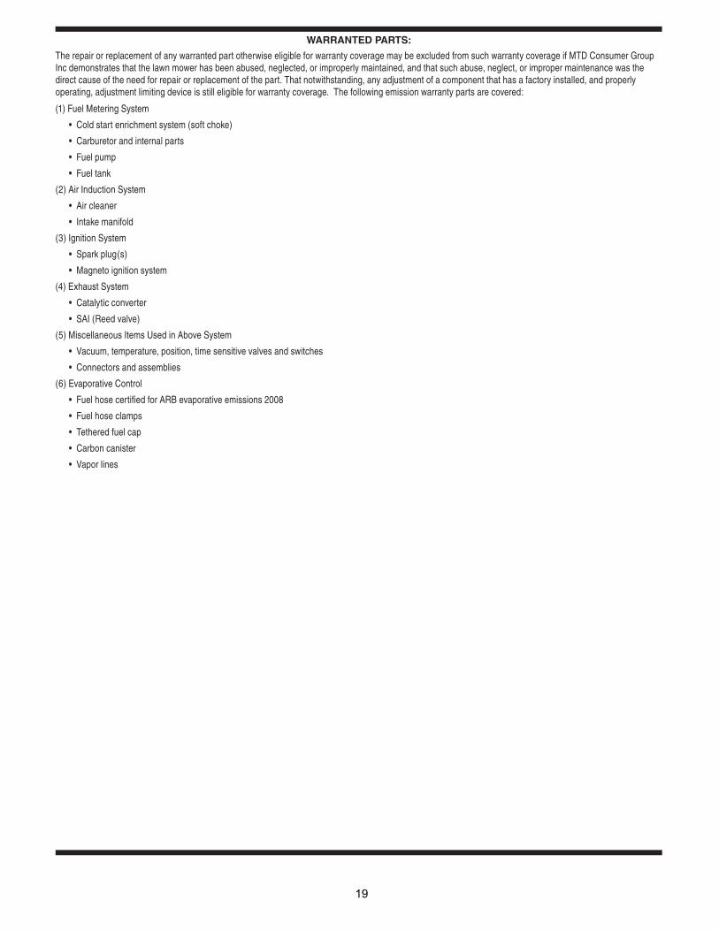
WARRANTED PARTS:
The repair or replacement of any warranted part otherwise eligible for warranty coverage may be excluded from such warranty coverage if MTD Consumer Group Inc demonstrates that the lawn mower has been abused, neglected, or improperly maintained, and that such abuse, neglect, or improper maintenance was the direct cause of the need for repair or replacement of the part. That notwithstanding, any adjustment of a component that has a factory installed, and properly operating, adjustment limiting device is still eligible for warranty coverage. The following emission warranty parts are covered:
(1) Fuel Metering System
(2) Air Induction System
(3) Ignition System
(4) Exhaust System
(5) Miscellaneous Items Used in Above System
(6) Evaporative Control
19

F
Cub Cadet LLC - P.O. Box 361131, Cleveland, Ohio 44136-0019; Phone 1-877-282-8684
MANUFACTURER’S LIMITED WARRANTY FOR CUB CADET COMMERCIALLAWN APPLICATION EQUIPMENT
IMPORTANT: To obtain warranty coverage owner may be required present proof of purchase and applicable maintenance records to the servicing dealer. Please see the operator’s manual for information on required maintenance and service intervals. In addition, Cub Cadet may deny warranty coverage if the hour meter, or any part thereof, is altered, modified, disconnected or otherwise tampered with.
The limited warranty set forth below is given by Cub Cadet LLC with respect to new merchandise used for commercial and related purposes purchased and used in the United States and/or its territories and possessions, and by MTD Products Limited with respect to new merchandise purchased and used in Canada and/or its territories and possessions (either entity respectively, “Cub Cadet”).
Cub Cadet warrants this product (excluding its No-Fault Components,as described below) against defects in material and workmanship for a period of one (1) year from the date of original retail purchase or lease and will, at its option, repair or replace, free of charge, any part found to be defective in materials or workmanship.
No-Fault Components include only belts, tires, and seats which are warranted to be free from defects in material and workmanship for a period of thirty (30) days from the date of original purchase or lease.
HOW TO OBTAIN SERVICE: Warranty service is available, WITH PROOF OF PURCHASE AND APPLICABLE MAINTAINCE RECORDS, through your local authorized service dealer. To locate the dealer in your area; In the U.S.A.:Check your Yellow Pages, or contact Cub Cadet LLC at P.O. Box 361131, Cleveland, Ohio 44136-0019, or call 1-877-282- 8684, or log on to our Web site at www.cubcadetcommercial.com.In Canada:For all provinces excluding Quebec contact Modern Power Products d/o MTD Canada Ltd. At 60 Ottawa Street South, Kitchener, Ontario N2G 3S7 or call 1-800-567-6775 or log on to our website at www.cubcadet.ca.
In Quebec contact Les Distributions RVI Ltee. d/o MTD Canada Ltd. 2955 jean-Baptiste Deschamps, Ville Lachine, Quebec H8T 1C5 or call 1-800-361-5770 or log on to our website at www.cubcadet.info.
This limited warranty does not provide coverage in the following cases: a. Routine maintenance items such as lubricants, filters, tune-
ups, brake adjustments, clutch adjustments, control linkages, drive system, engines, and normal deterioration of the exterior finish due to use or exposure.
b. Service completed by someone other than an authorized service dealer.
c. For products sold or exported outside of the United States and/or Canada, and their respective possessions and territories, except those sold through Cub Cadet’s authorized channels of export distribution.
d. Damage or failure resulting from the use of defective or improper peplacement parts and\or accessories other than genuine Cub Cadet parts.
e. Transportation charges and service calls. f. Failure to operate and maintain the product in accordance with
the Operator’s Manual furnished with the product, g. Damages and failures resulting from misuse, abuse, neglect,
accident, improper maintenance, alteration, vandalism, theft, fire, water, or damage because of other peril or natural disaster.
There are no implied warranties, including without limitation any implied warranty of merchantability or fitness for a particular purpose. No warranties shall apply after the applicable period of express written warranty above. No other express warranties beyond those mentioned above, given by any person or entity, including a dealer or retailer, with respect to any product, shall bind Cub Cadet. The exclusive remedy is repair or replacement of the product as set forth above. The terms of this warranty provide the sole and exclusive remedy arising from the sale and/or lease of the products covered hereby. Cub Cadet shall not be liable for any incidental or consequential loss or damage including, without limitation, expenses incurred for substitute or replacement lawn care services or for rental expenses to temporarily replace a warranted product.
Some jurisdictions do not allow the exclusion or limitation of incidental or consequential damages, or limitations on how long an implied warranty lasts, so the above exclusions or limitations may not apply to you. This limited warranty gives you specific legal rights, and you may also have other rights that vary in different jurisdictions.
In no event shall recovery of any kind be greater than the amount of the purchase price of the product sold. Alteration of safety features of the product shall void this warranty. You assume the risk and liability for loss, damage, or injury to you and your property and/or to others and their property arising out of improper use, misuse or inability to use the product. This limited warranty shall not extend to anyone other than the original purchaser/Leasee or to the person for whom it was purchased or leased as a gift.
orm #02004719 Rev. 08-3 05/20/2008