![Politecnico di Torino Porto Institutional Repository · 2017. 12. 15. · Politecnico di Torino Porto Institutional Repository [Book] The Wiener-Hopf method in electromagnetics Original](https://static.fdocuments.net/doc/165x107/5fdf1d7303a41571fa017e84/politecnico-di-torino-porto-institutional-repository-2017-12-15-politecnico.jpg)
Politecnico di Torino Porto Institutional Repository - … · Politecnico di Torino Porto...
91
Politecnico di Torino Porto Institutional Repository [Doctoral thesis] Software-based methods for Operating system dependability Original Citation: Alejandro David Velasco Carreño (2017). Software-based methods for Operating system dependability. PhD thesis Availability: This version is available at : http://porto.polito.it/2678125/ since: August 2017 Published version: DOI:10.6092/polito/porto/2678125 Terms of use: This article is made available under terms and conditions applicable to Open Access Policy Arti- cle ("Creative Commons: Attribution 3.0") , as described at http://porto.polito.it/terms_and_ conditions.html Porto, the institutional repository of the Politecnico di Torino, is provided by the University Library and the IT-Services. The aim is to enable open access to all the world. Please share with us how this access benefits you. Your story matters. (Article begins on next page)
Transcript of Politecnico di Torino Porto Institutional Repository - … · Politecnico di Torino Porto...
Politecnico di Torino
Porto Institutional Repository
[Doctoral thesis] Software-based methods for Operating systemdependability
Original Citation:Alejandro David Velasco Carreño (2017). Software-based methods for Operating systemdependability. PhD thesis
Availability:This version is available at : http://porto.polito.it/2678125/ since: August 2017
Published version:DOI:10.6092/polito/porto/2678125
Terms of use:This article is made available under terms and conditions applicable to Open Access Policy Arti-cle ("Creative Commons: Attribution 3.0") , as described at http://porto.polito.it/terms_and_conditions.html
Porto, the institutional repository of the Politecnico di Torino, is provided by the University Libraryand the IT-Services. The aim is to enable open access to all the world. Please share with us howthis access benefits you. Your story matters.
(Article begins on next page)
Doctoral Dissertation
Doctoral Program in Ingegneria Informatica E Dei Sistemi (29thcycle)
Software-based methods forOperating system dependability
By
Alejandro David Velasco Carreño******
Supervisor(s):Prof. Maurizio Rebaudengo
Doctoral Examination Committee:Prof. Alberto Bosio, Laboratoire d’Informatique, de Robotique et de Microélectron-ique de Montpellier, MontpellierProf. Michele Portolan, Laboratoire TIMA, GrenobleProf. Graziano Pravadelli, Università di Verona, VeronaProf. Luca Sterpone, Politecnico di Torino, TorinoProf. Massimo Violante, Politecnico di Torino, Torino
Politecnico di Torino
2017

Declaration
I hereby declare that, the contents and organization of this dissertation constitute myown original work and does not compromise in any way the rights of third parties,including those relating to the security of personal data.
Alejandro David Velasco Carreño2017
* This dissertation is presented in partial fulfillment of the requirements for Ph.D.degree in the Graduate School of Politecnico di Torino (ScuDo).


Acknowledgements
I would like to acknowledge supervisor Prof. Rebaudengo for the continuous supportof my Ph.D research activities. Additionally, I would like to acknowledge theresearch group composed by R. Ferrero, F. Gandino and B. Montrucchio for theirwork in our pubblications.
Abstract
Guaranteeing correct system behaviour in modern computer systems has becomeessential, in particular for safety-critical computer-based systems. However allmodern systems are susceptible to transient faults that can disrupt the intendedoperation and function of such systems. In order to evaluate the sensitivity of suchsystems, different methods have been developed, and among them Fault Injection isconsidered a valid approach widely adopted.
This document presents a fault injection tool, called Kernel-based Fault-InjectionTool Open-source (KITO), to analyze the effects of faults in memory elementscontaining kernel data structures belonging to a Unix-based Operating Systemand, in particular, elements involved in resources synchronization. This tool wasevaluated in different stages of its development with different experimental analysesby performing Faults Injections in the Operating System, while the system wassubject to stress from benchmark programs that use different elements of the Linuxkernel. The results showed that KITO was capable of generating faults in differentelements of the operating systems with limited intrusiveness, and that the datastructures belonging to synchronization aspects of the kernel are susceptible to anappreciable set of possible errors ranging from performance degradation to completesystem failure, thus preventing benchmark applications to perform their task.
Finally, aiming at overcoming the vulnerabilities discovered with KITO, a coupleof solutions have been proposed consisting in the implementation of hardening tech-niques in the source code of the Linux kernel, such as Triple Modular Redundancyand Error Detection And Correction codes. An experimental fault injection analysishas been conducted to evaluate the effectiveness of the proposed solutions. Resultshave shown that it is possible to successfully detect and correct the noxious effectsgenerated by single faults in the system with a limited performance overhead inkernel data structures of the Linux kernel.
Contents
List of Figures ix
List of Tables xi
1 Introduction 1
1.1 The Man Who Saved the World . . . . . . . . . . . . . . . . . . . . 1
1.2 Modern System Dependability . . . . . . . . . . . . . . . . . . . . 2
1.3 Fault Injections Methods . . . . . . . . . . . . . . . . . . . . . . . 3
1.3.1 Hardware-Implemented Fault Injection . . . . . . . . . . . 3
1.3.2 Simulation and Emulation Based Fault Injection . . . . . . 4
1.3.3 Software Implemented Fault Injection . . . . . . . . . . . . 6
1.4 Fault injection in Operating Systems . . . . . . . . . . . . . . . . . 7
1.5 Redundancy Techniques . . . . . . . . . . . . . . . . . . . . . . . 9
1.5.1 Redundancy in Computer systems . . . . . . . . . . . . . . 9
1.5.2 Multi-Threaded/Process Techniques . . . . . . . . . . . . . 11
1.6 Research Activity . . . . . . . . . . . . . . . . . . . . . . . . . . . 12
2 Synchronization in the Operating System 14
2.1 Synchronization in Linux Systems . . . . . . . . . . . . . . . . . . 14
2.2 Process Synchronization and the Process Control Block . . . . . . . 15
2.3 Mutex Semaphores . . . . . . . . . . . . . . . . . . . . . . . . . . 16

Contents vii
2.4 Atomic Operations . . . . . . . . . . . . . . . . . . . . . . . . . . 17
2.5 Loadable Kernel Modules . . . . . . . . . . . . . . . . . . . . . . . 18
3 Fault Injection Method 19
3.1 Fault Injection Tool . . . . . . . . . . . . . . . . . . . . . . . . . . 19
3.2 Module’s Internal Evolution . . . . . . . . . . . . . . . . . . . . . 20
3.2.1 KITO 0.a . . . . . . . . . . . . . . . . . . . . . . . . . . . 22
3.2.2 KITO 0.b . . . . . . . . . . . . . . . . . . . . . . . . . . . 23
3.2.3 KITO 1.0 . . . . . . . . . . . . . . . . . . . . . . . . . . . 24
3.2.4 KITO Insertion Examples . . . . . . . . . . . . . . . . . . 25
3.3 Address selection . . . . . . . . . . . . . . . . . . . . . . . . . . . 26
3.4 Timer Set-up . . . . . . . . . . . . . . . . . . . . . . . . . . . . . 29
3.5 Fault Injection . . . . . . . . . . . . . . . . . . . . . . . . . . . . . 30
4 Experimental Results 31
4.1 Tests Environments . . . . . . . . . . . . . . . . . . . . . . . . . . 31
4.2 Experiments Overall Set-up . . . . . . . . . . . . . . . . . . . . . . 32
4.3 Fault Effects Classification . . . . . . . . . . . . . . . . . . . . . . 34
4.4 Implemented Benchmarks . . . . . . . . . . . . . . . . . . . . . . 34
4.5 Tests I: First Mutex Semaphores Experiments . . . . . . . . . . . . 35
4.5.1 Results . . . . . . . . . . . . . . . . . . . . . . . . . . . . 36
4.6 Test II: First Process Control Block Experiments . . . . . . . . . . 36
4.6.1 Results . . . . . . . . . . . . . . . . . . . . . . . . . . . . 37
4.7 Test III: Extensive Experiments . . . . . . . . . . . . . . . . . . . . 39
4.7.1 Mutual Exclusion Semaphores Experiments Subset . . . . . 40
4.7.2 Process Control Block experiments Subset . . . . . . . . . 40
4.7.3 Results Analysis . . . . . . . . . . . . . . . . . . . . . . . 43
viii Contents
4.7.4 Effects on Performance . . . . . . . . . . . . . . . . . . . . 46
5 Redundant Techniques for Kernel Data Structures 51
5.1 The Mutex Mechanism . . . . . . . . . . . . . . . . . . . . . . . . 51
5.1.1 Fastpath and Slowpath Mutex Operations . . . . . . . . . . 52
5.2 Hardening Implementation . . . . . . . . . . . . . . . . . . . . . . 53
5.2.1 Voter Mechanism . . . . . . . . . . . . . . . . . . . . . . . 54
5.2.2 Mutex Update . . . . . . . . . . . . . . . . . . . . . . . . . 55
5.2.3 Implementation Examples . . . . . . . . . . . . . . . . . . 56
5.3 Experimental Results . . . . . . . . . . . . . . . . . . . . . . . . . 58
5.3.1 Experimental Set-up . . . . . . . . . . . . . . . . . . . . . 58
5.3.2 Performance Results Analysis . . . . . . . . . . . . . . . . 59
5.3.3 Fault Effect Results Analysis . . . . . . . . . . . . . . . . . 60
5.4 Process Synchronisation . . . . . . . . . . . . . . . . . . . . . . . 62
5.4.1 Redundancy Method . . . . . . . . . . . . . . . . . . . . . 62
6 Conclusions 66
References 68
Appendix A The KITO Module 73
Appendix B Doctoral Period’s Publications 78

List of Figures
1.1 Images from a translation of "Flight Manual: Ilyushin 2 Sturmovikwith a AM-38 Engine". . . . . . . . . . . . . . . . . . . . . . . . . 10
3.1 Scheme of KITO operation. . . . . . . . . . . . . . . . . . . . . . . 20
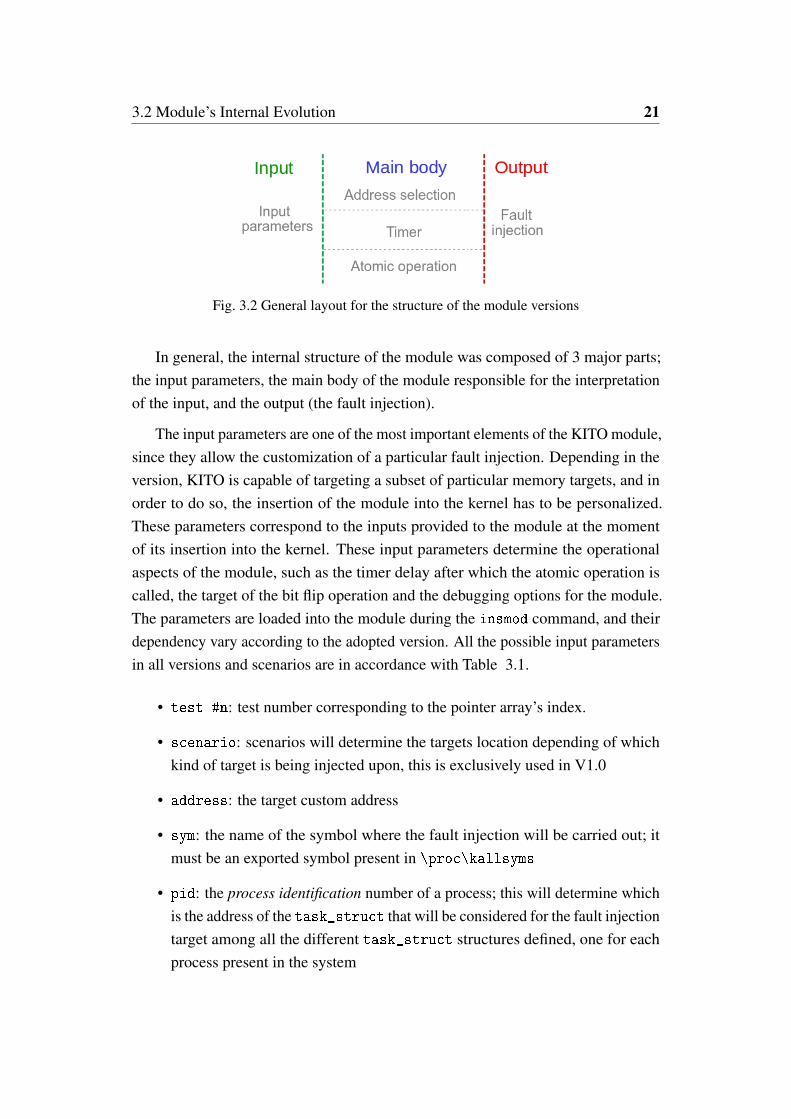
3.2 General layout for the structure of the module versions . . . . . . . 21
3.3 Scheme of the KITO 0.a Module structure . . . . . . . . . . . . . . 22
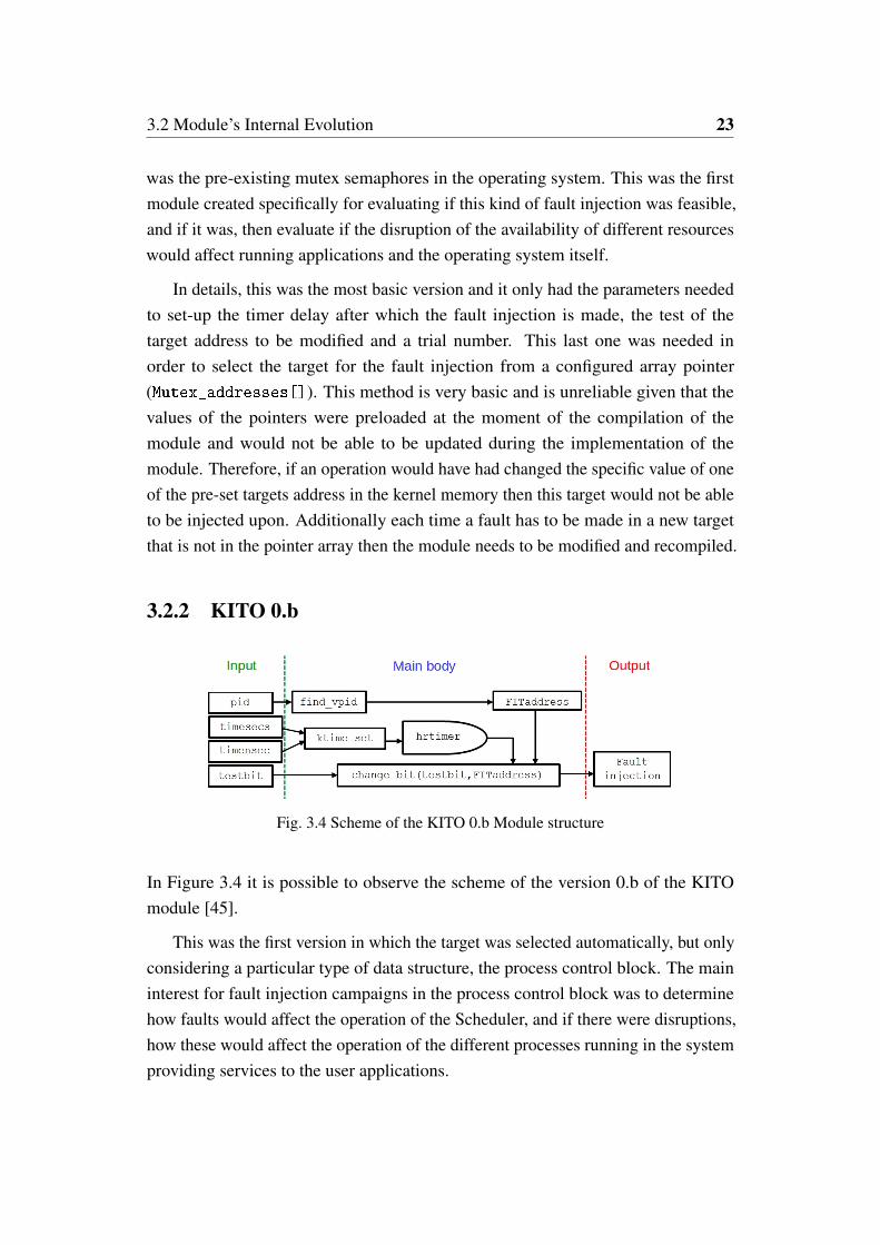
3.4 Scheme of the KITO 0.b Module structure . . . . . . . . . . . . . . 23
3.5 Scheme of the KITO 1.0 Module structure . . . . . . . . . . . . . . 25
4.1 General representation of each individual test carried out in thevirtual machine. . . . . . . . . . . . . . . . . . . . . . . . . . . . 33
4.2 Representation of the two layers model. . . . . . . . . . . . . . . . 37
4.3 Virtual Machine’s script flowchart . . . . . . . . . . . . . . . . . . 38
4.4 Performance of different experiments performed with IOzone3 Bench-mark. The top graph corresponds to faults affecting bit 0 in theflags field of task_truct. The bottom graph corresponds to faultsaffecting bit 0 in the Mutex semaphores. . . . . . . . . . . . . . . . 48
4.5 Performance of different tests performed with Netperf Benchmark.The top graph corresponds to the writing tests on bit 0 in the stateelement of task_truct. The bottom graph corresponds to the testson bit 0 in the Mutex semaphores. . . . . . . . . . . . . . . . . . . 49
x List of Figures
5.1 Simplified diagram of the subsystems of the mutex system and theircomponents. . . . . . . . . . . . . . . . . . . . . . . . . . . . . . . 52
5.2 Implementation of fastpath and slowpath scenarios. . . . . . . . . . 54
5.3 Original definition of the state fields values. . . . . . . . . . . . . . 63
5.4 a) Duplication of the state field values. b) Detection and correctionof a single fault in the new duplicated value. c) Problem with themodification resulting in a TASK_RUNNING value. . . . . . . . . . . 64
5.5 Final values for each half of the variables for the proposed redefini-tion of the state field. In darker gray the original values. . . . . . . 65
List of Tables
3.1 Scenarios parameters requirements . . . . . . . . . . . . . . . . . . 25
4.1 Tests Environments . . . . . . . . . . . . . . . . . . . . . . . . . . 32
4.2 Distribution of the results . . . . . . . . . . . . . . . . . . . . . . . 38
4.3 Values of the state field of the task_struct. . . . . . . . . . . . 41
4.4 Valid codes of the flags field of the task_struct. . . . . . . . . . 42
4.5 Distribution of the results for the fault injections in the Mutexsemaphores. . . . . . . . . . . . . . . . . . . . . . . . . . . . . . . 43
4.6 Distribution of the results for the state field of the task_struct. . 44
4.7 Distribution of the results for the flags field of the task_struct. . 45
4.8 Connection issues in Netperf experiments . . . . . . . . . . . . . . 50
5.1 Scenarios for the experimental campaign . . . . . . . . . . . . . . . 59
5.2 Performance overhead analysis . . . . . . . . . . . . . . . . . . . . 60
5.3 Fault Injection Experimental Results. . . . . . . . . . . . . . . . . . 61

Chapter 1
Introduction
1.1 The Man Who Saved the World
On the 1st of September of 1983 a civilian flight of Korean airlines (KAL007) wasshot down by a soviet Sukhoi 15 interceptor killing all 269 occupants. The flightwas en route to Seoul from Anchorage, it deviated from its planned course andviolated Soviet airspace twice, first at the Kamchatka Peninsula and then againat Sakhalin Island. This led to arguably one of the most tense moments of thecold war. Following the incident, the USA deployed nuclear capable Pershing IImissiles in West Germany generating an atmosphere similar to the 1962 missilecrisis, not even a month after this tragedy the situation would reach its apex. Onthe 26th September 1983, Lieutenant Colonel (LtCol.) Stanislav Petrov, was theduty officer overwatching the Oko early warning satellite system. Past midnight,the system notified of an Inter-Continental Ballistic Missile (ICBM) launched fromthe continental USA, heading towards the Soviet Union. LtCol. Petrov suspectedthat the alarm was a system malfunction and dismissed the alert given that no othersystem had detected the missile. In the following minutes four new ICBM launcheswere detected by the Oko system, and those alarms were also dismissed by LtCol.Petrov. The decision made by LtCol. Petrov was based on the assumption that anuclear attack from the USA would be a massive assault and not only with fivemissiles. By dismissing these alarms and reporting the event as false alarm to higherechelons LtCol. Petrov may have prevented a nuclear war.
2 Introduction
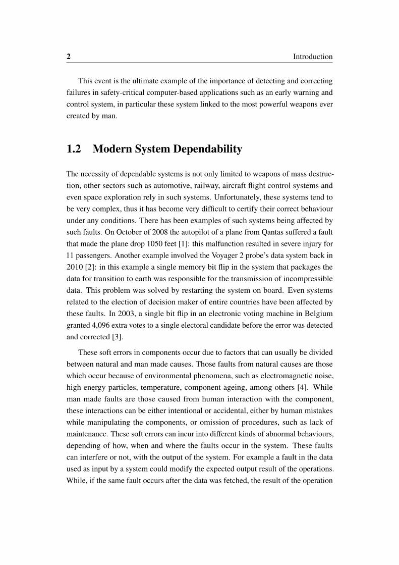
This event is the ultimate example of the importance of detecting and correctingfailures in safety-critical computer-based applications such as an early warning andcontrol system, in particular these system linked to the most powerful weapons evercreated by man.
1.2 Modern System Dependability
The necessity of dependable systems is not only limited to weapons of mass destruc-tion, other sectors such as automotive, railway, aircraft flight control systems andeven space exploration rely in such systems. Unfortunately, these systems tend tobe very complex, thus it has become very difficult to certify their correct behaviourunder any conditions. There has been examples of such systems being affected bysuch faults. On October of 2008 the autopilot of a plane from Qantas suffered a faultthat made the plane drop 1050 feet [1]: this malfunction resulted in severe injury for11 passengers. Another example involved the Voyager 2 probe’s data system back in2010 [2]: in this example a single memory bit flip in the system that packages thedata for transition to earth was responsible for the transmission of incompressibledata. This problem was solved by restarting the system on board. Even systemsrelated to the election of decision maker of entire countries have been affected bythese faults. In 2003, a single bit flip in an electronic voting machine in Belgiumgranted 4,096 extra votes to a single electoral candidate before the error was detectedand corrected [3].
These soft errors in components occur due to factors that can usually be dividedbetween natural and man made causes. Those faults from natural causes are thosewhich occur because of environmental phenomena, such as electromagnetic noise,high energy particles, temperature, component ageing, among others [4]. Whileman made faults are those caused from human interaction with the component,these interactions can be either intentional or accidental, either by human mistakeswhile manipulating the components, or omission of procedures, such as lack ofmaintenance. These soft errors can incur into different kinds of abnormal behaviours,depending of how, when and where the faults occur in the system. These faultscan interfere or not, with the output of the system. For example a fault in the dataused as input by a system could modify the expected output result of the operations.While, if the same fault occurs after the data was fetched, the result of the operation
1.3 Fault Injections Methods 3
is not affected. Additionally, apart from inferring with the normal operation of thesystems, these faults could also have a high probability of damage the system as themagnitude of the electric charges used to store information continues to decrease [4].
Nowadays, availability is strictly required for all digital systems directly linkedto human safety or economic interests. Therefore, dependability of a system must beevaluated, and in order to do so, fault occurrence has to be artificially acceleratedto better understand how the system reacts to faults. For this reason many methodshave been developed, and among those, the most common is Fault Injection [5, 6].Many safety standards, e.g., IEC 61508 [7], require fault injection campaigns to beperformed as one of a number of software validation activities. Fault injection toolstend to modify the user applications, introducing faults in the input and stored dataor the code segments of the running process as well as into the registers and memorylocations it uses.
1.3 Fault Injections Methods
In order to show the variety of possible fault injections, this section introduces thedifferent fault injection methods adopted in recent years and presents examples ofsuch implementations. Different fault injection techniques can be analyzed accordingto the following characteristics [8]:
• Controllability: the ability to control the time and location of the fault injection
• Repeatability: the ability to repeat the experiments
• Reproducibility: the ability to recreate a result
• Intrusiveness: the undesired ability to impact the normal operation of thesystem apart from the fault injection.
1.3.1 Hardware-Implemented Fault Injection
Hardware-implemented fault injection allows to inject faults by physical meansin the systems. Implementation on hardware can allow very high injection timecontrollability, however, can be severely lacking in terms of spatial controllability,

4 Introduction
meaning that the location where to make the fault injection can be very limited andinaccurate. The most common hardware-implemented fault injection techniques canbe summarized as follows.
In pin-level fault injection [9], by forcing pull ups or pull downs on pins of an ICenable, it is possible to make injection of faults in the system. There are limitationsto controllability, given that not all the pins are reachable in modern ICs, however,this approach presents very high reproducibility and temporal controllability.
A commonly used approach is heavy-ion fault injection [10], the IC under studyis bombarded with heavy electrically charged isotopes. Another similar techniqueis electromagnetic interference fault injection [11], and in this method inductiongenerators are used as means of fault injector. Both of these approaches possesnegligible intrusiveness, but also negligible controllability of a particular location,therefore, reproducibility is particularly difficult to achieve.
Background debug mode fault injection (BDM) [12] exploits built-in test anddebug capabilities of modern microprocessors. Given that these capabilities areprovided by the supplier, the reproducibility of this technique is high, but suffers ofa significant degree of intrusiveness.
The most common drawback of hardware fault injection techniques is the veryhigh implementation cost, particularly true for heavy-ion and electromagnetic in-terference fault injection techniques. Furthermore, in some of these fault injectionmethods the risk of damaging the system under test is sometimes unavoidable. Addi-tionally, the elapsed time to complete a fault injection campaign suffers for the needto restart the system after each experiment.
1.3.2 Simulation and Emulation Based Fault Injection
Simulation-based fault injection refers to techniques that implement computer systemmodels to simulate faults at electrical circuit level, gate level or higher levels in IC,such as full components. Simulation provides a basic representation of the system (inparticular when concerning the input and output of the system), but doesn’t respectcompletely with all rules of the system. While Emulation-based fault injection isthe technique that implements a computer whole system’s rules and environments toallow the execution of the fault injection in the emulated models.

1.3 Fault Injections Methods 5
A typical approach is to generate tools to evaluate circuit models considering thetypical soft error characteristics. As an example, [13] presents a library developedto predict single errors rates in combinational circuits, by taking into considerationtypical current responses of different soft error characteristics. While in [8], a toolcalled MODIFI (MODel-Implemented Fault Injection) is capable to simulate faultsby means of a XML defined model for Simulink while the algorithm for the faultinjection uses minimal cut sets.
Other simulation-based tools, such as MEFISTO [14], implement faults by meansof saboteurs. These saboteurs are additional or modified (mutant) components that re-place healthy (fault free) components in a system. In the particular case of MEFISTOthis evaluation is made in a VHDL environment. A similar technique is implementedin [15], where saboteurs are implemented by using commercial debugging tools fromAltera. Evaluation of faults effects in state-of-the-art technologies such as quantumcircuits has also been done implementing simulation based fault injection, as can beseen in [16]. This example used the implementation of saboteurs and mutants intothe VHDL models of quantum circuits.
These techniques tend to be intensive in computing time given the complexityof such systems. An example of their level of complexity can be seen in DEPEND[17]. This tool provides a fault injection environment for system level dependabilityanalysis, simulating an Unix-based Tandem Triple-Modular-Redundancy (TMR)based fault-tolerant system.
In [18] fault emulation for VLSI circuits is discussed, and the proposed FPGAemulation system allows to speed up the fault injection campaigns by taking the speedcharacteristics of hardware faults implementation, and the versatility of simulationbased fault injection.
Finally, in [19] an emulation environment is proposed for testing of ICs inprototypal phases by means of an optimized framework.
One drawback of these systems is the confidence in the outcome of the fault inelements that are not considered in fault injection campaigns. In [20] a method toquantify the confidence in both the reported results and the estimation of the effectsof unsurveyed faults in order to improve the margin of error such campaigns.
Both Simulation and emulation based fault injection techniques are remarkablyadvantageous in their high controllability, repeatability and reproducibility and

6 Introduction
negligible intrusiveness. Additionally, in both fault injection campaigns can be madebefore the prototypal stages of the system undergoing analysis. Notwithstanding,these techniques require huge amounts of computing power and time, together withthe fact that these requirements increase rapidly as the complexity of the systemincreases.
1.3.3 Software Implemented Fault Injection
Software implemented fault injection (SWIFI) is made by stimulating the conditionsthat a physical fault would have in software and data, by means of faults in the CPUregisters and/or memory elements. SWIFI techniques commonly implement memorybit flips, emulation of corrupt data segments or corrupt instructions in the softwareunder test. Among these techniques the difference is commonly the adopted injectionmethod.
FERRARI [21] implements a technique that injects faults into CPU registers,memory and bus by means of software traps. After a program reaches a certainpoint in its execution or by expiration of a timer, these traps are triggered; the faultinjection then is made by changing the contents of registers and memory via changesin the system calls in order to emulate corrupt data.
EDFI [22] operates by defining several faults which are triggered during theexecution of the program. This is achieved by introducing a controller componentprocess that uses a combination of dynamic and static source codes to insert adynamic fault model.
Xception [23] presents a tool that exploits the debugging and performance moni-toring features of modern COTS processors for injecting faults.
GOOFI [24] is a tool able to inject faults into the data area of programs beforetheir execution; this tool is capable to generate single or multiple transient faults.
G-SWFIT [25] is a technique for injecting faults in code, based in different typesof faults and their statistical frequency. This technique proposes a set of fault modeloperators that enable the injections of faults even when the source code of the targetprogram is not available.
Commonly SWIFI techniques target applications with very high repeatabilityand reproducibility. Depending on the methodology implemented, intrusiveness

1.4 Fault injection in Operating Systems 7
issues can be present. Additionally, controllability and time resolution on SWIFI canbe restricted to assembly level instructions with time limitations, therefore faults inthe pipeline of instructions are impossible. Commonly, faults are also restricted tospecific locations due to system architecture or privilege issues.
1.4 Fault injection in Operating Systems
Operating System reliability validation is quite difficult to achieve. Operating systemsreliability has been studied for decades [26, 27], nonetheless, it remains one of themajor areas of concern in many systems. The main reasons why operating systemdependability is an issue, has mainly to do with the fact that this systems are verycomplex. Operating systems often have to be capable of handling many different kindof systems and architectures. Furthermore, with each technological advancement inhardware and software, constant changes need to be made on different elements ofoperating systems to cope with the hardware and software evolution. And finally,many operating system are commercial focused and often the companies are notinterested in applying the diverse methods that have been developed to automaticallytest operating systems robustness in their development cycle.
One method was implemented in the Crashme program [28], where data com-posed of randomized values in memory were executed as code segments by a largenumbers of spawned processes. Similarly, the Fuzz project [29] used random noiseto data for discovering robustness issues in the operating systems.
Other commonly used approaches modify the execution of the system calls ofan operating system: in FERRARI [21], the system calls made by the processesare intercepted and then modified returning faulty values; BALLISTA [30] adopts asimilar approach that feeds random or erroneous inputs to the system call in order toevaluate the behaviour of the functions belonging to the POSIX-API.
In [31], faults are injected into the driver programming interface so that theeffects of faults on the device drivers can be characterized. Similarly, other attemptsto characterize the ability to cope with faults into the operating system functions wasmade in [32].
Software implemented fault injection is often focused in the application programsrunning in the system rather than in the operating system itself. Elements of the

8 Introduction
operating system provide services to higher applications and often these have beennot considered in the main dependability studies. In recent years, techniques havebeen developed to target the operating system. Some studies implemented simulationtools for fault injection in operating systems [33, 34]; such studies used softwaresuch as emulators or virtual machines. In these applications, functions are used toinject faults into the virtual environment where the Operating System is running. In[33] a Virtual Machine environment that operates in QEMU (an open source machineemulator and virtualizer) is presented, injecting faults into the CPU registers, RAMdata, storage system and networking I/O. In order to provide a wide scope of faultinjection targets, [33] proposes to inject faults into the environment of a virtualmachine; moreover, this method has a high complexity. In [34], faults are emulatedby mounting a virtual machine in a custom engine capable of generating injectionsinto elements of the machine such as memory elements, CPU registers and otherhardware elements. This is achieved by using a complex compiler frame designedto support analysis of programs and operating system code. This approach is verycomplex and a good knowledge of the application running the virtual machine isneeded.
In [35], fault injection is made into different signals from the CPU, the systemcalls and internal functions of the kernel. This is achieved by tracing the processesand tracking kernel calls, then the fault injection method introduces bit flips intothe parameters provided to the kernel call or the underlying kernel functions. Thisapproach is highly intrusive and requires the execution of the process to be stoppedin order to trace it.
The option of making fault injections via loadable kernel modules [36] is simpleand is a possible solution to the problem. Kernel modules are objects that areintroduced into the kernel and are capable of exporting kernel symbols that can befunctions or data structures. An implementation of such modules can be seen in [37]:this approach provides on-demand access to the application’s virtual address space,as well as to the processor’s context, and it injects into the applications’ data segmentand code segment, omitting the elements of the kernel that provide services to theapplications.

1.5 Redundancy Techniques 9
1.5 Redundancy Techniques
After fault injections have determined which parts of a system are critical the fol-lowing step typically is to add mechanisms to the system that enables the detectionand recovery from possible faults. In order to do so, different techniques have beendeveloped over the years, and most of these techniques can posses one or more ofthe following characteristics:
• Modular redundancy: different elements of the systems are multiplied and theymay be used in parallel in order to determine if a fault has affected the output.
• Time redundancy: specific elements of the system are run multiple times insequence and the output are compared to check for faulty results.
• Information redundancy: The information used by the system is multipliedand additional data (check-codes) can be added in order to detect any fault.
• Versions redundancy: Multiple versions of the system or its modules areproduced so that these systems are immune to particular faults affecting theother versions.
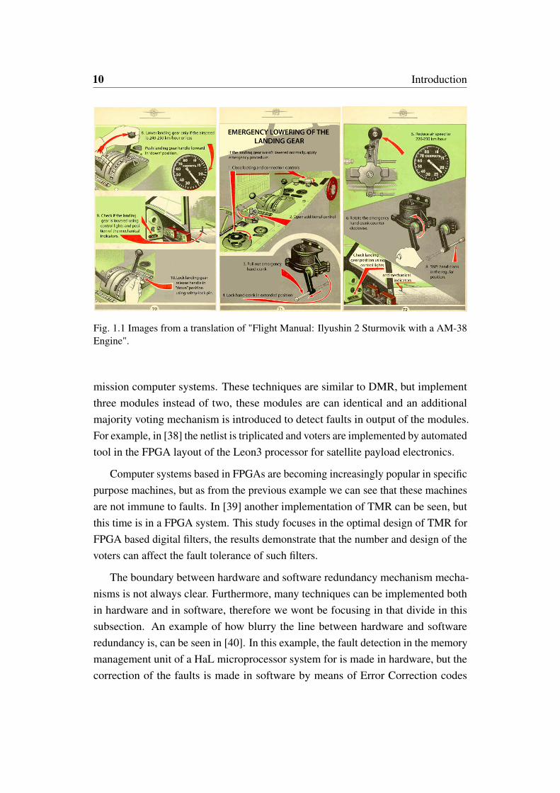
Techniques using these principles have been implemented for a long time. Forexample, during the second world war some planes (e.g. Ilyushin 2 Sturmovik) hada dual landing gear system, the main system was an pneumatic system, but in thecase of failure or damage, this system could be disconnected, and then a hand crankwould allow the pilot to lower the landing gear using a mechanical system. Thisexample is the implementation of Dual Modular Redundancy (DMR), and in thiscase, redundancy technique is using modular redundancy and version redundancy.The modular part comes from the fact that the module is being duplicated, in thesense that an additional module is installed that performs the same operation ofthe original, but this module is a different version because it operates in a purelymechanical and not pneumatic-mechanical principle.
1.5.1 Redundancy in Computer systems
These kind of modular redundancy techniques are still relevant, in computer systemsit is quite common to find Triple Modular Redundancy techniques in modern critical
10 Introduction
Fig. 1.1 Images from a translation of "Flight Manual: Ilyushin 2 Sturmovik with a AM-38Engine".
mission computer systems. These techniques are similar to DMR, but implementthree modules instead of two, these modules are can identical and an additionalmajority voting mechanism is introduced to detect faults in output of the modules.For example, in [38] the netlist is triplicated and voters are implemented by automatedtool in the FPGA layout of the Leon3 processor for satellite payload electronics.
Computer systems based in FPGAs are becoming increasingly popular in specificpurpose machines, but as from the previous example we can see that these machinesare not immune to faults. In [39] another implementation of TMR can be seen, butthis time is in a FPGA system. This study focuses in the optimal design of TMR forFPGA based digital filters, the results demonstrate that the number and design of thevoters can affect the fault tolerance of such filters.
The boundary between hardware and software redundancy mechanism mecha-nisms is not always clear. Furthermore, many techniques can be implemented bothin hardware and in software, therefore we wont be focusing in that divide in thissubsection. An example of how blurry the line between hardware and softwareredundancy is, can be seen in [40]. In this example, the fault detection in the memorymanagement unit of a HaL microprocessor system for is made in hardware, but thecorrection of the faults is made in software by means of Error Correction codes
1.5 Redundancy Techniques 11
(ECC). Error Correction codes (ECC) are processes that add redundancy by encodingthe output of an operation with additional information. These techniques encompasscommon techniques such as Cyclic Redundancy Check (CRC) and Hamming codes.These kind of approaches are quite common and are currently being implementedin the state of the art, as it can be seen in [41]. In this example hardening is intro-duced to a selected set of memory elements belonging to the kernel of particularapplication machines by using approaches such as Hamming and CRC codes. Theelements of the kernel to harden are selected by profiling the system of these particu-lar application machines in order to determine which elements are critical as far asdependability is considered.
Techniques such as CRC are known and well researched, but these techniquesare still evolving. In [42], 48 new polygons are proposed for CRC providing goodperformance for CRC checks up to 2048 bits data segments.
Redundancy techniques have also been developed for technologies such as Dis-tributed Computing Architectures. In [43] a dynamic voting approach is proposed,this approach adapts to changes in the environments executing the vote, this approachcan be applied to distributed systems that posses multiple different resources pools.
1.5.2 Multi-Threaded/Process Techniques
If the redundancy technique is implemented in software, then there is another impor-tant characteristic defining this implementation. This characteristic describes howthe technique is introduced to the system in terms of number of threads/processes.
Local-thread Multiplication is the implementation of a technique that executemultiple executions of a critical segment of code in a single thread. The results ofeach critical segment of code is stored and after all the executions are done, thencompared. The main drawback of this technique is that the overhead in processingtimes is usually high, given that each segment of code is executed in sequence.Nonetheless this technique is extremely efficient in the usage of CPU Cache, andalso this technique does not require any kind of synchronization mechanisms withother threads.
Software Redundant Multi-Thread is the implementation of a technique that isbased in the implementation of the critical segments of code in identical threads,each in an individual core. After each thread has been completed all the results

12 Introduction
are compared, if they differ, then that implies that a fault is detected, dependingin how many threads are used then it can be also corrected. In terms of time, thistechnique is more efficient than local thread, but requires some sort of multi-threadcommunications mechanism.
Process-level redundancy, this approach is based in the implementation of mul-tiple instances of a program running and then comparing only the output. Thesemultiple instances are not multiple threads in a single application but the applicationas a whole. This means the usage of multiple resources and processing time. Addi-tionally, depending in the nature of the process being protected, this technique canhave limited overhead impact and large effect in the memory imprint of the processbeing hardened.
1.6 Research Activity
Given the open source nature of Linux-based system, such systems have becomevery attractive for dependability studies, this is accentuated by the ever increasingnumber of systems that are supported, e.g. commercial embedded systems, Androiddevices, etc. Considering the proposed approaches available in literature, it wouldappear that there was no technique that considers analysis of the effects of faults inkernel data structures in Linux based systems.
The main research activity was divided into two phases. The first phase wasfocused in evaluating the effects of faults affecting specific kernel data structures,in order to assess how critical these fields are for system dependability [44–46].A fault injection method was investigated and refined and it was based in a novelfault injection tool, called Kernel-based fault-Injection Tool Open source (KITO).Considering that the kernel space stores many different types of elements, the toolprovides the possibility of an easy and rapid access to several different componentsof the operating system, such as process control blocks and kernel symbols. Addi-tionally, the tool provides a means of customizing the target of the fault injectionto any memory address containing an element belonging to the kernel space. Setsof experimental tests were executed in different kernel data structures and environ-ments, while running a set of benchmark programs in order to stress the operatingsystem. This document presents a detailed analysis of the effects of the faults in

1.6 Research Activity 13
the Linux Kernel, demonstrating that soft errors affecting the kernel may producecritical effects and failures in user applications.
The second phase of the research was focused in adding redundancy mechanismsto the Linux kernel, fixing some of the issues that arose from the experimental results.These solutions were made considering Local-thread multiplication informationredundancy approaches. The proposed fault injection technique and the redundancymethod presented promising results, and the method was capable of injecting faultsinto a variety of targets of the kernel space, and redundant techniques seem to beable to detect and/or correct most of failures affecting these systems.
Additional studies could spawn from the approaches described in this thesis byconsidering other elements of the operating system not considered in this document.

Chapter 2
Synchronization in the OperatingSystem
This research focuses in the implementation of fault injection methods in the datastructures used by the main services provided by the Linux kernel, in particularfocusing in those providing processes and resources synchronization. An introductionof the basics of the different elements considered in this research is preliminarilyreported in this chapter.
2.1 Synchronization in Linux Systems
The main task of an Operating System is to manage the physical and virtual resourcesof the machine it is operating on [47]. These resources are then provided to differentProcesses, which are defined as instances of execution of a group of instructionsexecuted in sequence in order to achieve a goal. Typically, computers run a multitudeof processes; therefore, the need of different mechanisms allowing access to thelimited different resources of the computer at a given time. One of such resources isCPU time, meaning that a CPU’s core is processing the instructions that compose aprocess. In order to switch from one process to another one without interfering withthe others’ work, a synchronization mechanism needs to be implemented.
2.2 Process Synchronization and the Process Control Block 15
2.2 Process Synchronization and the Process ControlBlock
The scheduler is the entity that is responsible for synchronizing and switching fromone process to the next one. In the case of Linux, since kernel version 2.6.23,the implemented scheduler is the Completely Fair Scheduler (CFS). The CFS is ascheduler based in a run queue that operates with a Red-Black Tree (a self-balancingbinary data-search tree) to obtain future tasks to be executed, guaranteeing a fair timefor insertion, search and deletion of a task in the tree. Additionally, the CFS operateswith nanosecond accounting to determine the virtual runtime of the a process insteadof working with counters. This means, that it bases its decision on the amount of timethat the process has been running in the system and not on the values of counters,such as jiffies. This is done aiming to achieve precise multi-tasking. This is the ideaof implementing hardware to run multiple tasks in parallel at the same speed: inorder to follow this policy, the CFS also determines the order of the Red-Black Treerun queue by the priority and/or the virtual runtime of each process indexed in theRed-Black Tree. The schedulers often base their decision in the information presentabout each process in the system, and this information is often stored in kernel datastructures such as the Process Control Block (PCB), a kernel data structure thatis created for each process present in the system. The name of the PCB used byCFS is task_struct. The task_struct contains necessary information for thescheduler and some additional information for debugging and other operations, andthis includes over a hundred fields of different variable types, pointers and others.Among those fields, the ones that are relevant to the studies presented in this thesisare the following:
• PID: each process present in the system has a unique identifier number, calledProcess Identifier (PID);
• state: current state of the process; e.g, running or waiting for an interrupt, ifthe task is being traced, etc;
• thread_info->flags: flags of the process; e.g., if the process is beingterminated, allocating memory or if it was killed by a signal;
• prio & static_prio: the priority of the task to be selected and if this wouldpreempt the current running task; for normal processes it ranges between 100

16 Synchronization in the Operating System
and 139. Only one of these fields is used, depending on the mode that thescheduler is running;
• rt_priority: used for real-time applications with priority ranging between0 and 99.
Among all the different fields in the process control block, the ones consideredfor fault injection campaigns in this research activity were the state, the flags andthe prio fields.
2.3 Mutex Semaphores
So far we have taken into consideration process synchronization in order to managethe amount of time that a process is being served by a CPU. Additional resourcesare present in most computer systems, and one mechanism to manage the access ofdifferent processes to these resources are the semaphores [47]. In this section we aregoing to have a look to the mutex semaphores.
The mutex semaphores or mutual exclusion semaphores are used in the synchro-nization of the different resources that a computer possesses. Semaphores are kernelsymbols that are defined as structures that contain a binary-like semaphore to solveproblems of mutual exclusion for shared resources, race conditions and/or criticalcode sections. This data structure is defined as follows:
struct mutex {
atomic_t count;
spinlock_t wait_lock;
struct list_head wait_list;
...Debug options...
}
The variable count is the semaphore itself. The semaphore is unlocked whenthe count variable is 1. A value of 0 for the count variable indicates that the mutexsemaphore is locked. Finally, when this variable is negative, the mutex semaphoreis locked and possesses a waiting list. When the semaphore is locked, the fieldwait_lock indicates the current task controlling the mutex semaphore, whereaswait_list corresponds to the list of processes waiting for the resource.
2.4 Atomic Operations 17
As mentioned before, the mutex semaphores are defined as kernel symbols. AKernel symbol is an easy way to share variables and functions among differentelements of the kernel. These symbols are shared by using the EXPORT_SYMBOL()function. Exported symbols are then indexed in a list called kallsyms which islocated in the proc pseudo file-system. In addition, the kernel symbols systemprovides functions that will allow import of data from the proc pseudo file-systemdirectly to modules. One of such functions is kallsyms_lookup_name(), whichreturns the address of any symbol with the name provided to this function as inputparameter. These functions will be utilized for the localization of the target mutexsemaphores address during the implementation of the fault injection campaignsdescribed in this document.
2.4 Atomic Operations
An atomic operation is an uninterruptible operation short enough to be consideredinstantaneous and indivisible. The Linux headers provide several atomic operationsin their libraries, mainly logic and arithmetic operations. Because of the nature ofthe Linux headers libraries, these functions support different hardware architectures.These functions are often written in GAS (GNU assembler macro), and are inde-pendent of the computer’s processor architecture. These operations are particularlyeffective in terms of process cycle execution.
Among these atomic operations, the work described in this thesis is based in theimplementation of the change_bit() function. This atomic operation allows a sin-gle bit flip to be made on a particular address. This atomic operation is implementedas follows:
int foo=42;
change_bit(0,&foo);
change_bit(1,&foo);
In the previous example, the value of the variable foo is set initially to 42(101010 in binary). With the first execution, the bit 0 (least significant) is changedso foo would become 43 (101011 in binary). Then, with the second execution thebit 1 (second least significant bit) is changed, therefore the final value for foo is 41(101001 in binary).
18 Synchronization in the Operating System
2.5 Loadable Kernel Modules
Loadable kernel modules are relocatable object code [36], that can be dynamicallyloaded (inserted) and unloaded (removed) from the kernel. The drivers are the mostcommon type of loadable kernel modules, however not all modules are drivers norall drivers are modules, some drivers are loaded into the linux kernel files located in/boot/. All modules operate by means of callback function that are triggered whenthe modules is loaded into the kernel, via the insmod command, and when they areunloaded from the kernel, via the rmmod. The most simple module is the following:
#include <linux/module.h>
#include <linux/kernel.h>// Needed for printing in dmesg
int init_module(void)
{
printk(KERN_INFO "Hello world.\n");
return 0;
}
void cleanup_module(void)
{
printk(KERN_INFO "Goodbye world.\n");
}
In the previous example, the Hello world version of the module can be seen. Thefunction that is called when the module is loaded is triggered by the init_module()macro. While the function that is called when the module is unloaded is triggered bythe cleanup_module(). In the previous example the module would simply log intothe driver messages log systems the messages "Hello world" and " Goodbye world",when the module is loaded and unloaded, respectively.

Chapter 3
Fault Injection Method
In this chapter the main mechanism utilized in the implementation of the faultinjections campaign is discussed.
3.1 Fault Injection Tool
The implemented approach consisted in performing a injection of transient faults ina memory element by means of a loadable module inserted in the kernel [36]; thefault injection is performed in an atomic bit-flip manner, in any predefined Kernelspace memory location at a defined time after the module’s insertion. The modulecreated for this approach has been called KITO (Kernel-based fault-Injection ToolOpen source) and was described in [46]. This module is fully customizable bythe parameters provided during the module insertion command (insmod). Afterthe insertion of the module in the kernel, a High Resolution timer (hrtimer) isprogrammed by the KITO’s module. The created timer triggers an atomic operationupon its expiration, and this atomic operation is responsible of making the faultinjection by means of an atomic binary flip in the target memory element. Thetimer duration and the memory target address location of the fault can be fullycustomizable, as explained in the following sections. KITO can’t inject a stuck-atfault, only generates erroneous information in memory data structures, but the datacan be manipulated afterwards.

20 Fault Injection Method
Fig. 3.1 Scheme of KITO operation.
Figure 3.1 describes the operation of KITO: at the top a large black blockportraits the kernel, that contains the kernel processes, the data structures and theKITO module. The user’s processes are outside the kernel block; these processes usethe services of the kernel in order to execute the applications. During the insertion ofthe module into the kernel, it is configured in order to set up the internal variablesused to define the fault injection target address and the duration of the timer delay.This set-up is represented by the KITO Initialization block. The timer delay isthe time that the module will wait for a software interrupt in order to inject thefault. Finally, the fault injection block corresponds to the execution of the faultinjection function which possesses a single atomic bit flip operation in order tointroduce a fault in the memory elements of the kernel (kernel data structures orkernel processes).
3.2 Module’s Internal Evolution
During the different stages of this research different versions of KITO were imple-mented. There were three major versions that were implemented during experimentalcampaigns, and are presented in this section.
3.2 Module’s Internal Evolution 21
Fig. 3.2 General layout for the structure of the module versions
In general, the internal structure of the module was composed of 3 major parts;the input parameters, the main body of the module responsible for the interpretationof the input, and the output (the fault injection).
The input parameters are one of the most important elements of the KITO module,since they allow the customization of a particular fault injection. Depending in theversion, KITO is capable of targeting a subset of particular memory targets, and inorder to do so, the insertion of the module into the kernel has to be personalized.These parameters correspond to the inputs provided to the module at the momentof its insertion into the kernel. These input parameters determine the operationalaspects of the module, such as the timer delay after which the atomic operation iscalled, the target of the bit flip operation and the debugging options for the module.The parameters are loaded into the module during the insmod command, and theirdependency vary according to the adopted version. All the possible input parametersin all versions and scenarios are in accordance with Table 3.1.
• test #n: test number corresponding to the pointer array’s index.
• scenario: scenarios will determine the targets location depending of whichkind of target is being injected upon, this is exclusively used in V1.0
• address: the target custom address
• sym: the name of the symbol where the fault injection will be carried out; itmust be an exported symbol present in \proc\kallsyms
• pid: the process identification number of a process; this will determine whichis the address of the task_struct that will be considered for the fault injectiontarget among all the different task_struct structures defined, one for eachprocess present in the system

22 Fault Injection Method
• testbit: it selects which bit will be modified in the target address
• timesecs: first component of the amount of timer delay for the fault injection(in seconds)
• timensecs: second component of the amount of timer delay for the faultinjection (in nanoseconds)
• debug: enables the debugging messages in the dmesg system (display mes-sages or driver messages). This is always optional, independent of the valueof scenario.
The main body is composed of three subcomponents; the selection of the targetaddress, the setting up of the timer and the bit flip atomic operation responsiblefor the fault injection. In figure 3.2 it is possible to see the layout of the differentcomponents of the KITO module, this layout is going to be used in the descriptionof the different implemented versions. Finally, The output corresponds to the atomicoperation performed by the module in a memory location.
The main difference in all versions can be found exclusively in two of the mainmodule’s components: the input parameters and the selection of the target address.All other components were identical in all versions of the KITO module.
3.2.1 KITO 0.a
Fig. 3.3 Scheme of the KITO 0.a Module structure
In Figure 3.3 it is possible to observe the scheme of the version 0.a of the KITOmodule [44], the only possible target for this version of the loadable kernel module
3.2 Module’s Internal Evolution 23
was the pre-existing mutex semaphores in the operating system. This was the firstmodule created specifically for evaluating if this kind of fault injection was feasible,and if it was, then evaluate if the disruption of the availability of different resourceswould affect running applications and the operating system itself.
In details, this was the most basic version and it only had the parameters neededto set-up the timer delay after which the fault injection is made, the test of thetarget address to be modified and a trial number. This last one was needed inorder to select the target for the fault injection from a configured array pointer(Mutex_addresses[]). This method is very basic and is unreliable given that thevalues of the pointers were preloaded at the moment of the compilation of themodule and would not be able to be updated during the implementation of themodule. Therefore, if an operation would have had changed the specific value of oneof the pre-set targets address in the kernel memory then this target would not be ableto be injected upon. Additionally each time a fault has to be made in a new targetthat is not in the pointer array then the module needs to be modified and recompiled.
3.2.2 KITO 0.b
Fig. 3.4 Scheme of the KITO 0.b Module structure
In Figure 3.4 it is possible to observe the scheme of the version 0.b of the KITOmodule [45].
This was the first version in which the target was selected automatically, but onlyconsidering a particular type of data structure, the process control block. The maininterest for fault injection campaigns in the process control block was to determinehow faults would affect the operation of the Scheduler, and if there were disruptions,how these would affect the operation of the different processes running in the systemproviding services to the user applications.

24 Fault Injection Method
In this version the limitations of version 0.a were overcome, because that nomodification in the Linux kernel would prevent the operation of the module and norecompilation is needed when targeting new addresses in memory. Nonetheless, thisis true only when considering a particular type of data structure, the Process ControlBlock. As explained in section 2.2, this structure is unique for each process thatexists in the system, and contains large amounts of information of the operation ofthe Scheduler. This automatic address selection process will be explained in detailin the following version.
3.2.3 KITO 1.0
KITO version 1.0 is the most complete version of the fault injection module utilizedin this research activity [46]. KITO 1.0 included the automatic address selectionmechanism from version 0.b, and additional mechanisms were included. The mostnovel aspect of this version is that in theory is not limited to a specific fault injectiontarget type unlike it’s predecessors, the main idea was to generate a fault injectiontool capable of generating faults in all memory elements of the kernel space. And inorder to do so, in this version some of the input module parameters are optional andothers are mandatory depending on the nature of the intended target in memory. So,in order to organize the dependencies of all the parameters, different predeterminedscenarios were defined as follows:
• Custom address: A particular address can be targeted for fault injection
• Kernel symbol: The module will automatically obtain the base address of thetarget symbol given its symbol name
• Process descriptor: Any element of the task_struct of any process presentedin the system, given the PID value, can be set as a target.

3.2 Module’s Internal Evolution 25
Fig. 3.5 Scheme of the KITO 1.0 Module structure
Table 3.1 Scenarios parameters requirements
ScenarioTarget
TimerAddress bit offset
Custom Address testbit timesecs
address timensecs
Kernel Sym testbit timesecs
Symbol timensecs
Process PID testbit timesecs
descriptor timensecs
In Table 3.1, the first column corresponds to the fault injection scenario in whichthe module is going to operate. The target is the necessary information for theselection of the target address, this column is composed of two sub-columns: the first(left) indicates which field needs to be provided to the insmod command in orderto automatically obtain the corresponding address location. Whereas, the secondsub-column (right) indicates which is the bit of the obtained address that is goingto be modified. In the right, the Timer column is shared among all the scenarios,and corresponds to the amount of time that the timer is going to be waiting beforemaking the fault injection into the kernel.
3.2.4 KITO Insertion Examples
In order to clarify how the module is inserted into the kernel here are some examples.
insmod KITO.ko scenario=1 sym=swapon_mutex testbit=1 timesecs=5

26 Fault Injection Method
In this first example, the KITO module is inserted in the kernel using scenario1 (Kernel symbol) and makes a fault injection in the second least significant bit(testbit set to 1) from the base variable of the structure defining swapon_mutex.The fault injection is made 5 seconds after the insertion of the module to the kernel.
sudo grep 'swapon_mutex' /proc/kallsyms
ffffffff96874540 d swapon_mutex
insmod KITO.ko scenario=0 address=18446744071940031808 testbit=1
timesecs=5
The second example is equivalent to the first one. In this case the address of theswapon mutex is given directly as a pointer address (18446744071940031808 indecimal).
insmod KITO.ko scenario=2 pid=1 testbit=5 timesecs=2
timensecs=500000000 debug=1
In this third example, the KITO module is inserted in the kernel using scenario2 (Process descriptor) and makes a fault injection in the 6th least significant bit(testbit set to 5) from a programmed field of the process descriptor of the processwith a PID value of 1, commonly init (depending in the initialization daemon). Thefault injection is made 2,5 seconds after the insertion of the module to the kernel (2seconds plus 500000000 nanoseconds). Additionally this insertion of the modulewill display debug messages in the dmesg system.
3.3 Address selection
In order to determine where the fault is going to be injected, a pointer needs to bedefined. This pointer was called FITaddress. The selection of the content of thispointer is done differently for each of the scenarios.
In the Custom address scenario, the address variable loaded from the param-eters is copied directly into the FITaddress pointer. It is important to take intoconsideration that the custom address needs to be a logical variable. The modulecannot set the target address to have a base value for the bit flip operation in the
3.3 Address selection 27
internal of a logical element. If the user wants to inject faults in the middle bit ofa memory variable, then FITaddress must correspond to the base value for thevariable in question and testbit is the offset to select the particular bit.
In the kernel symbol scenario, the address will be obtained by the kallsyms_lookup_name and the sym parameter function.
FITaddress = kallsyms_lookup_name(sym);
The symbol’s name is provided in a string format in sym. This is providedduring the insertion of the module as an input parameter. The lookup name functionwill automatically obtain the address of sym from the kallsyms file in the /proc/pseudo-file system. In order to modify a symbol of a structure nature or similar,an offset can be made directly into FITaddress, but it is strongly recommended tomake structure pointer of the desired target and use the container_of() macro.
#define offsetof(TYPE, MEMBER) ((size_t) &((TYPE *)0)->MEMBER)
#define container_of(ptr, type, member) ({ \
const typeof( ((type *)0)->member ) *__mptr = (ptr); \
(type *)( (char *)__mptr - offsetof(type,member) );})
struct some_list {
int var_3;
};
struct some_struct {
int var_1;
int var_2;
struct some_list list;
};
int main()
{
// Original structure
struct some_struct original_struct;
original_struct.var_1 = 33;

28 Fault Injection Method
original_struct.var_2 = 114;
original_struct.list.var_3 = 42;
// Pointer to an element of the original structure
struct some_list *element_pointer = &original_struct.list;
//Return of the pointer structure
struct some_struct *return_pointer_struct = container_of(\
element_pointer, struct some_struct, list);
printf("var_1 = %d\n", return_pointer_struct->var_1);
printf("var_2 = %d\n", return_pointer_struct->var_2);
printf("var_3 = %d\n", return_pointer_struct->list.var_3);
/* The values printed are 33, 114 adn 42, and are read from
a pointer structure. */
return 0;
}
In this example of the application of the container_of() macro, we provide apointer to one of the elements of an already defined structure (*element_pointer),and then we can obtain a pointer structure (return_pointer_struct) to everysingle element of the original structure. In order to apply this to KITO we just takeone of the elements of this pointer structure as FITaddress.
Finally, for the process descriptor scenario, it is necessary to provide the PIDnumber of the considered process. In this case, the value of the PID must be given totwo functions:
• find_vpid(): this function will search for the identifier by its ID
• pid_task(): this function will obtain the address of all the fields in thetask_struct and store it into a structure pointer; additionally, it is necessaryto specify which ID type is provided to this function. The possible types areprocess ID, process group ID and Session ID. In the case of the KITO module,PIDTYPE_PID indicates that pid_task() must search for a process ID.
3.4 Timer Set-up 29
The following lines of code correspond to the implementation of both functionspreviously described in order to load the target of the pointers into the FITaddressvariable.
struct task_struct *t = pid_task(find_vpid(pid),PIDTYPE_PID);
FITaddress = &((*t).state);
In the previous example, the first line takes every single field of the targettask_struct and stores their address in a pointer structure called t. Then in thesecond line, the address of the state field of the process control block is goingto be saved in the FITaddress. In order to select another target field from thetask_struct the state in this line needs to be replaced with the desired field, andthen the module recompiled. This is made in order to leave the module as clean aspossible regarding the elements that are not directly involved in the fault injectionprocess. The more logic introduced, the more complex the module becomes, andparticularly complex when considering data structures such as the task_struct.Furthermore, the larger the logic sections are in the set-up phase, the more CPU timethis section will take to complete.
Finally, when using the optional debugging messages in the dmesg (displaymessage or driver message), the declaration of the format of &FITaddress in theoutput strings needs to be modified according to the target’s data type. For exampleif the desired target is an integer the format must be %d in the different printk lines,but of the desired target is an float, then %f needs to be placed in these lines.
3.4 Timer Set-up
The delay after which the fault injection is made is done by means of a high resolutiontimer (hrtimer). This timer is defined in the Linux libraries and operates using ared/black tree self-balancing structure where the first timer to expire is at the head.After the expiration of this timer a callback function is called. This function isresponsible of the fault injection. The full implementation of the hrtimer is asfollows:
delay_in_secs = timesecs;
30 Fault Injection Method
delay_in_ns = timensecs;
ktime = ktime_set( delay_in_secs, delay_in_ns );
hrtimer_init( &hr_timer, CLOCK_MONOTONIC, HRTIMER_MODE_REL );
hr_timer.function = &fi_hrtimer_callback;
hrtimer_start( &hr_timer, ktime, HRTIMER_MODE_REL );
The first three lines set the variables for the duration of the timer. Then the fourthline initializes the timer structure and the operation modes of this timer. This imple-mentation, the clock tick is set to CLOCK_MONOTONIC which indicates that the startvalue of the tick counter is going to be zero, and the mode is HRTIMER_MODE_REL in-dicating that the time measurement is a relative time amount after the creation of thetimer, and not an absolute time value of the computer’s internal clock. The followingline sets the pointer to the function that is called after the expiration of the timer(callback function), and in this case the function is called fi_hrtimer_callback.Finally, the last lines starts the timer.
3.5 Fault Injection
The fault injection is made in the callback function of the timer. This function isdefined as follows:
enum hrtimer_restart fi_hrtimer_callback(struct hrtimer *timer)
{
change_bit(testbit,FITaddress);
return HRTIMER_NORESTART;
}
The function change_bit(testbit,FITaddress) is the fault injection itself.This is an atomic operation from asm/bitops.h. This function performs a single bit-flip in the (testbit+1)th least significant bit of the value stored in the FITaddressaddress. The following line returns the function, and indicates that there is no needto restart the timer.
Chapter 4
Experimental Results
In this chapter the implementation of the different experimental campaigns are goingto be discussed. These experimental campaigns had a similar set-up with differentvariations in terms of contexts, target, and kernel versions. These differences aregoing to be explained in detail in each individual case, and the overall approach ispresented.
4.1 Tests Environments
Different tests had different environments configurations. These configurationsdepended in which version of the KITO module was implemented, which kind ofmachine was hosting the experiments, which were the target among others. Evenwhen a quick overlook of these tests environments can be seen in Table 4.1, eachsection of the individual experiments described in this chapter will introduce exten-sive details of the environment in order to demonstrate why these experiments aresignificant and novel, in particular, in the effects that faults can have in differentkinds of targets.
The fields of Table 4.1 have the following definitions:
• Tests: describe the name of the tests and each test will be referred in a sectionin this chapter.
• KITO Ver.: KITO version implemented during the test.

32 Experimental Results
Table 4.1 Tests Environments
Tests KITO Ver. Test Machine Target #FI Kernel
Test I V0.a Live Mutex 450 3.3.7
Test II V0.b Virtual PCB (state) 703 3.11.0-15
Tests III V1.0 Virtual Mutex 9056 3.18.20
PCB (state)
PCB (flags)
PCB (prio)
• Test Machine: kind of machine that hosted the experiments. There were twokind of machines: live machines, for tests made directly in hardware; VirtualMachines, for tests running in a virtualized environment.
• Target: What kind of data structure was injected upon in each experimentalcampaign. Mutex indicates fault injections made to the mutex semaphores,while PCB indicates fault injections made into a Process Control Block.
• #FI: Number of Fault injections made in each experiment.
• Kernel: Kernel Version in which fault injections were made.
4.2 Experiments Overall Set-up
The general implementation of experiments using the loadable kernel module wasmade automatically by a bash scripts loaded in the rc.local files. The RC.localis the first script that the user of a Linux based machine’s boot can modify withoutthe need of recompiling the kernel. This script is executed directly by the kernel,thus any script inside this file will have kernel-level privileges, and this is the featurethat is exploited by the KITO module. In addition to the fault injection moduleinsertion, a benchmark program is ran in parallel in order to stress the operatingsystem in an operational condition. After the completion of this benchmark program,the computer will reboot and perform the following fault injection test. In order toguarantee that the experiments are performed in identical conditions, all tests wereperformed in machines with ram-disks. A ram-disk is a logical file-system unit thatis setup using the system’s RAM memory, therefore it is a volatile file-system thatguarantee identical conditions with each reboot. A representation of each individual

4.2 Experiments Overall Set-up 33
fault injection test is described in Figure 4.1, the time is represented in the horizontalaxis and it is not to scale, and each individual fault injection time in a campaign iscustomizable down to nanoseconds by means of hr-timer.
Fig. 4.1 General representation of each individual test carried out in the virtual machine.
The different blocks in Figure 4.1 are the following:
• BIOS: the check of the devices in the machine.
• Master Boot Record (MBR) check: the check of the first record in the filesystem that describes the distribution of different partitions and boot optionsof the systems installed on them.
• GRUB/LILO: the element that manages the options given by the MBR andtakes a decision in the boot or presents the options to the user.
• Kernel: loads the kernel fetch code into the system memory and takes over themanagement of the machine resources.
• init: the first process created in the system; all processes will be created bythe execution of system calls from init or its childrens.
• Kernel processes: all the processes initialized by the kernel that are responsiblefor providing services to higher level applications.
• KITO: the insertion of the module that manages the fault injection. Themodule is inserted into the system by the rc.local script, without making amodification in the kernel, with a less intrusive approach.
34 Experimental Results
• Benchmark Programs: just after the KITO module insertion into the kernel, abenchmark is executed by means of the rc.local script. After the conclusionof the benchmark program a reboot is executed.
4.3 Fault Effects Classification
In all experimental campaigns there were observable noxious effects to the operatingsystem. These effects took place after the fault injection and modify the way thatthe operating system behaved. In order to classify these fault effects we took thecharacteristics of the abnormal behaviour presented by the operating system andclassified the effects accordingly. The full list of effects is the following:
• POF (Power Off Failure): After the benchmark program completed its op-eration the operating system remained idle and did not begin the power-offprocedure (or reboot).
• SHPO (System Hanged in Power Off): The system stops while executing thepower off during system reboot. This means that the benchmark program wasexecuted and its operation completed.
• SDPO (System Delayed Power Off): The system took longer than usual topower-off during the reboot, up to twelve minutes.
• BUI (Broken User Interface): The User Interface (UI) of the system brokegenerating digital artifacts and bugged windows, but the operation of thesystem carried on.
• BS (Black Screen): the system hanged during the execution of the benchmarkand the machine was unresponsive with a black-screen. Consequentially, thebenchmark program operation did not complete.
4.4 Implemented Benchmarks
During the different experimental campaigns a variety of benchmarks were imple-mented to stress the machine in which the fault injection was performed. Thesebenchmarks were the following:
4.5 Tests I: First Mutex Semaphores Experiments 35
• IOzone3 [48]: a tool that generates and simulates Input-Output operations. Ad-ditionally, IOzone3 provides metrics on the amounts of operations performed.In particular, the operations are performed as writing and reading operationsin the File-system.
• Netperf [48]: a client-server tool to evaluate the network performance, par-ticularly in TCP/IP. This tool provides metrics on the data transfer rate andprocessing rate of the connection between the server and the client.
• Matrix product (MP): A 1500x1500 matrix multiplication program is used tosimulate CPU intensive operations.
• SCP: a client-server application used to evaluate the I/O operations in conjunc-tion with network communications.
• GZIP: the compression of a file generates heavy load in the CPU and alsoon I/O operations in the file system, thus combining CPU and I/O-boundapplications.
In all the applications of these benchmarks the output was taken into consider-ation. When possible the tests output was compared to the output from a goldenexperiment version of the test, meaning comparing the metrics and the binary differ-ence of the output files.
4.5 Tests I: First Mutex Semaphores Experiments
The basic elements of the fault injection method were tested in this study. Theinjection in memory implementing a fault with a timer and an atomic operation wereconducted with success up to a certain degree. In this early version of the KITOmodule, all the parameters for the fault injection were in the code of the loadablekernel module, giving no degree of customization of the target address. All addresseswere loaded into an array with the pointer address to the mutex semaphores extractedfrom the proc pseudo file system manually. This experimental campaign based inthis method was presented in [44], and were made into a live machine using Linuxkernel version 3.3.7. Additionally the delays were programmed into two differentpre-set times. Two different benchmarks were implemented in the tests, Gzip andSCP.

36 Experimental Results
4.5.1 Results
During this experimental campaign the classification system was not established yet,but a total of 4.44% of the test presented some kind of abnormal behaviour. Theeffects of faults in the mutex semaphores was revisited in the experiments of section4.7.
4.6 Test II: First Process Control Block Experiments
The general set up of the experiments were following the guidelines described insection 4.2. There were significant differences in this experimental campaign, themain being the target of the fault injection campaign. In this campaign the faultswere injected into the state field of the process control block. This experimentalcampaign was also the first time when the target was automatically selected usingthe functions provided by the Linux headers libraries. Finally, this fault injectioncampaign took place in virtual machines instead of live machines, probing that asimulation based environment is viable with this method. Both the virtual machinesand the host machines were running with Linux kernel version 3.11.0-15, and thevirtual machines environment was made with Virtual Box 4.1.12.
Given that the test were performed in virtual machines, there was the need fora mechanism to pass the experimental results from the virtual machine to the hostmachine. For this, a shared folder file system was implemented between the host andvirtual machines. All of the files managing the different process descriptions for theautomated decision of the target were placed in this file system. In order to managethese two layers (host machine and virtual machine) and the files in the shared filesystem, an additional layer of scripts was introduced that would manage the creationand destruction of virtual machines and would store the results in the output folder, agraphic representation of this two layer model can be seen in figure 4.2.
The virtual machine layer has a script that follows the set-up described in Section4.2. This script takes name of every single process in the system at the moment of thetest (anything before the RC.local execution), then picks the first process that hasnot been selected before in a previous test, and then proceeds to insert the moduleto make a fault injection to the state field of the task_struct of the selected
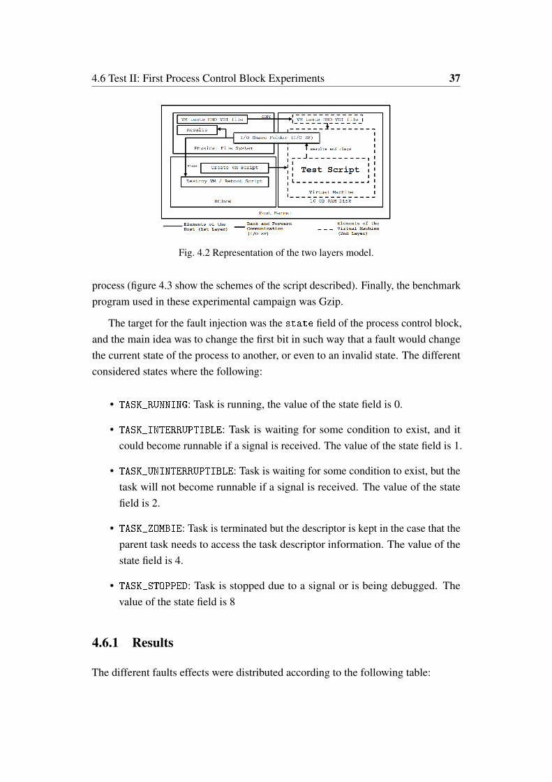
4.6 Test II: First Process Control Block Experiments 37
Fig. 4.2 Representation of the two layers model.
process (figure 4.3 show the schemes of the script described). Finally, the benchmarkprogram used in these experimental campaign was Gzip.
The target for the fault injection was the state field of the process control block,and the main idea was to change the first bit in such way that a fault would changethe current state of the process to another, or even to an invalid state. The differentconsidered states where the following:
• TASK_RUNNING: Task is running, the value of the state field is 0.
• TASK_INTERRUPTIBLE: Task is waiting for some condition to exist, and itcould become runnable if a signal is received. The value of the state field is 1.
• TASK_UNINTERRUPTIBLE: Task is waiting for some condition to exist, but thetask will not become runnable if a signal is received. The value of the statefield is 2.
• TASK_ZOMBIE: Task is terminated but the descriptor is kept in the case that theparent task needs to access the task descriptor information. The value of thestate field is 4.
• TASK_STOPPED: Task is stopped due to a signal or is being debugged. Thevalue of the state field is 8
4.6.1 Results
The different faults effects were distributed according to the following table:
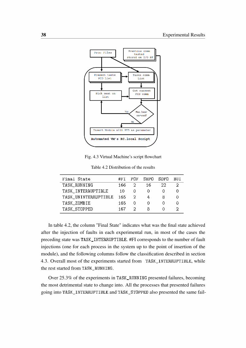
38 Experimental Results
Fig. 4.3 Virtual Machine’s script flowchart
Table 4.2 Distribution of the results
Final State #FI POF SHPO SDPO BUI
TASK_RUNNING 166 2 16 22 2
TASK_INTERRUPTIBLE 10 0 0 0 0
TASK_UNINTERRUPTIBLE 165 2 4 8 0
TASK_ZOMBIE 165 0 0 0 0
TASK_STOPPED 167 2 8 0 2
In table 4.2, the column "Final State" indicates what was the final state achievedafter the injection of faults in each experimental run, in most of the cases thepreceding state was TASK_INTERRUPTIBLE. #FI corresponds to the number of faultinjections (one for each process in the system up to the point of insertion of themodule), and the following columns follow the classification described in section4.3. Overall most of the experiments started from TASK_INTERRUPTIBLE, whilethe rest started from TASK_RUNNING.
Over 25.3% of the experiments in TASK_RUNNING presented failures, becomingthe most detrimental state to change into. All the processes that presented failuresgoing into TASK_INTERRUPTIBLE and TASK_STOPPED also presented the same fail-
4.7 Test III: Extensive Experiments 39
ures going into TASK_RUNNING. But from all the considered processes only Init
and RC presented failures going into TASK_RUNNING, TASK_INTERRUPTIBLE andTASK_STOPPED. Apart from these processes, not a single process that presented an ab-normal behaviour was shared between TASK_INTERRUPTIBLE and TASK_STOPPED.
Additional experiments were made also to test an invalid state, i.e., putting thestate to a value not recognized as a valid one. A total of 166 experiments were carriedout for each bit and in all the cases no detrimental consequence on the system wasdetected.
4.7 Test III: Extensive Experiments
In this subsection the experiments are made in the final version of the KITO faultinjection module. All the experiments carried out to determine the effectiveness ofKITO. These tests were made in elements belonging to the process synchronizationand resource locking aspects of the Kernel. The experimental set-up was made inan identical Virtual machine environment to the one used in section 4.6, but thistime the virtual machines were running in Virtual-Box 4.1.12 and all Linux kernelversions were 3.18.20. As like in section 4.6, all experiments were loaded into theRC.local of the virtual machines scripts to run the benchmark program.
Experiments were performed to evaluate the capabilities of the KITO module.These experiments consist of fault injections into different elements of the kernel’sprocess synchronization while running a benchmark program. A greater numberof benchmarks have been adopted, and these benchmarks were selected due to thedifferent nature of the stress that they place on the operating system. The adoptedbenchmark programs are IOzone3, Netperf, Matrix product, and Gzip.
The hard-disks of the virtual machines running these experiments were loadedinto a ram-disk in order to avoid fragmentation issues and to ensure that every test isbeing run from the same starting point. Additionally, following the same guidelinesused in section 4.6, all the information about the results was stored in the file systemof the hosting machine via shared-folders.
The fault injection campaigns considered two main targets:
40 Experimental Results
• The semaphores: Faults are injected into count variable inside the mutexsemaphore data structure.
• The Process Control Block: Faults are injected into three different samplefields of the task_struct (state, flags and prio).
The rc.local scripts will execute the tests using kernel level privileges. In eachtest the bits considered are analyzed by 2 individual injections at random times.
4.7.1 Mutual Exclusion Semaphores Experiments Subset
Faults were injected into the mutex semaphore structure’s count variable. Asexplained in chapter 2, the expected values of the count variable are 1 when thesemaphore is free, 0 when it is locked and a negative value when the semaphore islocked with a waiting list, which is a FIFO queue. The bits targeted were the mostsignificant one (bit 31), the second least significant (bit 1) and the least significant(bit 0). For this experiment, a list of all the existing mutex semaphores in the systemwas extracted from the /proc/ pseudo-files, and a total of 161 mutexes listed in/proc/kallsyms were covered. These mutexes were feed to the module via theinsert parameters (scenario, sym, pid and testbit).
4.7.2 Process Control Block experiments Subset
Since the main goal is to evaluate the reliability of the kernel elements providingservices to user applications, all the tasks that exist up to the point of execution of therc.local script were considered, given that most of these are processes belongingto the kernel.
As explained in chapter 3, the KITO module receives a PID number and au-tomatically obtains the address pointer to the task_struct associated with suchPID number. The first process loaded in the Linux kernel is always init (with theassigned value 1); after init, several different tasks will be created with a specificPID value. Up to a certain point in the boot, PIDs tend to be identical from rebootto reboot, with low PID numbers, but afterwards, the PID values are differentlyassigned to tasks almost in a random way.
Three fields of the task_struct have been considered:

4.7 Test III: Extensive Experiments 41
• state
• flags
• prio.
Table 4.3 Values of the state field of the task_struct.
Possible state Variable valueTASK_RUNNING 0TASK_INTERRUPTIBLE 1TASK_UNINTERRUPTIBLE 2__TASK_STOPPED 4__TASK_TRACED 8EXIT_DEAD 16EXIT_ZOMBIE 32EXIT_TRACE 96TASK_DEAD 64TASK_WAKEKILL 128TASK_WAKING 256TASK_PARKED 512TASK_STATE_MAX 1024
The defined state values present in the Linux version 3.18.20 are described intable 4.3. Given the results of [45] the most common state is TASK_INTERRUPTIBLE.Therefore, in accordance with table 4.3, the value 0 is the only possible valueachievable after a single fault injection for most states; this value corresponds tothe state TASK_RUNNING. All the other states would require to have as a startingvalue TASK_RUNNING, or in the case of EXIT_TRACE, it is necessary to start fromEXIT_ZOMBIE and EXIT_DEAD, or vice versa. This last scenario is highly unlikely,therefore it was not considered for tests. In most other cases the value would carryto a value not valid and not defined in the table. Additionally from [45] a singlefault injection would most likely provide a faulty behaviour by changing the stateto a valid state, therefore in this case to TASK_RUNNING. As a result, the tests wereconducted with particular attention to bit 0. Additionally other bits were tested todetermine the effects of non valid states, these bits were bit 1 and bit 2.
The flags field is an integer containing the flags of the processes, and it isdefined in a bit map. The fault injection experiments focus on the effects of faults in

42 Experimental Results
the process flag PF_EXITING (0x00000004). With this value, the process would beflagged for termination, and it will be held in a wait state before releasing the memoryand the resources assigned to it. Thus, by modifying this flag we are expecting tostop a process that would affect others in a cascading effect. Additionally, both bit1 and 0 (0x00000002 and 0x00000001) are taken as references to determine theeffects of non defined flags bits. The full list of flags is presented in Table 4.4.
Table 4.4 Valid codes of the flags field of the task_struct.
Flag Variable value MeaningPF_EXITING 0x00000004 Getting shut downPF_EXITPIDONE 0x00000008 PI exit done on shut downPF_VCPU 0x00000010 A virtual CPUPF_WQ_WORKER 0x00000020 A workqueue workerPF_FORKNOEXEC 0x00000040 Forked but didn’t execPF_MCE_PROCESS 0x00000080 Process policy on mce errorsPF_SUPERPRIV 0x00000100 Used super-user privilegesPF_DUMPCORE 0x00000200 Dumped corePF_SIGNALED 0x00000400 Killed by a signalPF_MEMALLOC 0x00000800 Allocating memoryPF_NPROC_EXCEEDED 0x00001000 RLIMIT_NPROC was exceededPF_USED_MATH 0x00002000 FPU must be initialized beforePF_USED_ASYNC 0x00004000 Used async_schedule*()PF_NOFREEZE 0x00008000 Should not be frozenPF_FROZEN 0x00010000 Frozen for system suspendPF_FSTRANS 0x00020000 In a filesystem transactionPF_KSWAPD 0x00040000 A kswapdPF_MEMALLOC_NOIO 0x00080000 Allocating memory without IOPF_LESS_THROTTLE 0x00100000 Throttle lessPF_KTHREAD 0x00200000 A kernel threadPF_RANDOMIZE 0x00400000 Randomize virtual address spacePF_SWAPWRITE 0x00800000 Allowed to write to swapPF_SPREAD_PAGE 0x01000000 Spread page cache over cpusetPF_SPREAD_SLAB 0x02000000 Spread some slab caches over cpusetPF_NO_SETAFFINITY 0x04000000 Not allowed use with cpus_allowedPF_MCE_EARLY 0x08000000 Early kill for mce process policyPF_MEMPOLICY 0x10000000 Non-default NUMA mempolicyPF_MUTEX_TESTER 0x20000000 Belongs to the rt mutex testerPF_FREEZER_SKIP 0x40000000 Should not count it as freezablePF_SUSPEND_TASK 0x80000000 Called freeze_processes

4.7 Test III: Extensive Experiments 43
Table 4.5 Distribution of the results for the fault injections in the Mutex semaphores.
IOZONE3
Bit # #FI POF SHPO SDPO BUI BS
Bit 0 322 4 40 0 2 2
Bit 1 322 0 0 0 0 0
Bit 31 322 2 37 0 0 0
NETPERF
Bit # #FI POF SHPO SDPO BUI BS
Bit 0 322 4 36 0 2 2
Bit 1 322 0 0 0 0 0
Bit 31 322 2 30 0 0 0
MP
Bit # #FI POF SHPO SDPO BUI BS
Bit 0 322 4 40 0 2 2
Bit 1 322 0 0 0 0 0
Bit 31 322 2 36 0 0 0
GZIP
Bit # #FI POF SHPO SDPO BUI BS
Bit 0 322 4 41 0 2 2
Bit 1 322 0 0 0 0 0
Bit 31 322 2 38 0 0 0
In the case of prio, the priority value may be changed. As explained in chapter2, the priority range are split between 0 and 99 for real time processes and from100 upwards is for normal processes. So, a bit flip in the 7th least significant bitchanges the priority mode from real time to normal (and vice versa). Moreover, otherexperiments targeted the two least significant bits changing only the value of thepriority and not the priority type (dynamic priority and real time priority).
4.7.3 Results Analysis
The effects of the faults were classified in accordance to the definition of effectsdescribed in section 4.3. Failures that have observable behaviour were distributed intables 4.5, 4.6 and 4.7.
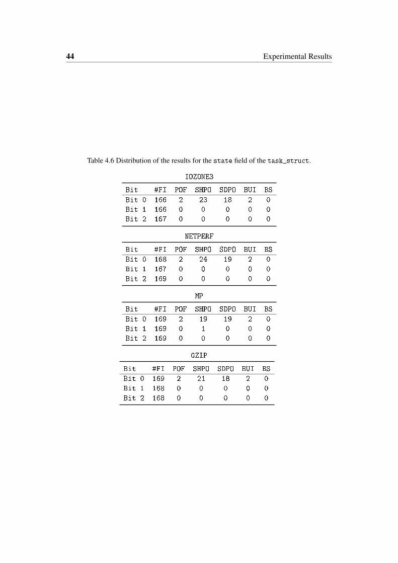
44 Experimental Results
Table 4.6 Distribution of the results for the state field of the task_struct.
IOZONE3
Bit #FI POF SHPO SDPO BUI BS
Bit 0 166 2 23 18 2 0
Bit 1 166 0 0 0 0 0
Bit 2 167 0 0 0 0 0
NETPERF
Bit #FI POF SHPO SDPO BUI BS
Bit 0 168 2 24 19 2 0
Bit 1 167 0 0 0 0 0
Bit 2 169 0 0 0 0 0
MP
Bit #FI POF SHPO SDPO BUI BS
Bit 0 169 2 19 19 2 0
Bit 1 169 0 1 0 0 0
Bit 2 169 0 0 0 0 0
GZIP
Bit #FI POF SHPO SDPO BUI BS
Bit 0 169 2 21 18 2 0
Bit 1 168 0 0 0 0 0
Bit 2 168 0 0 0 0 0
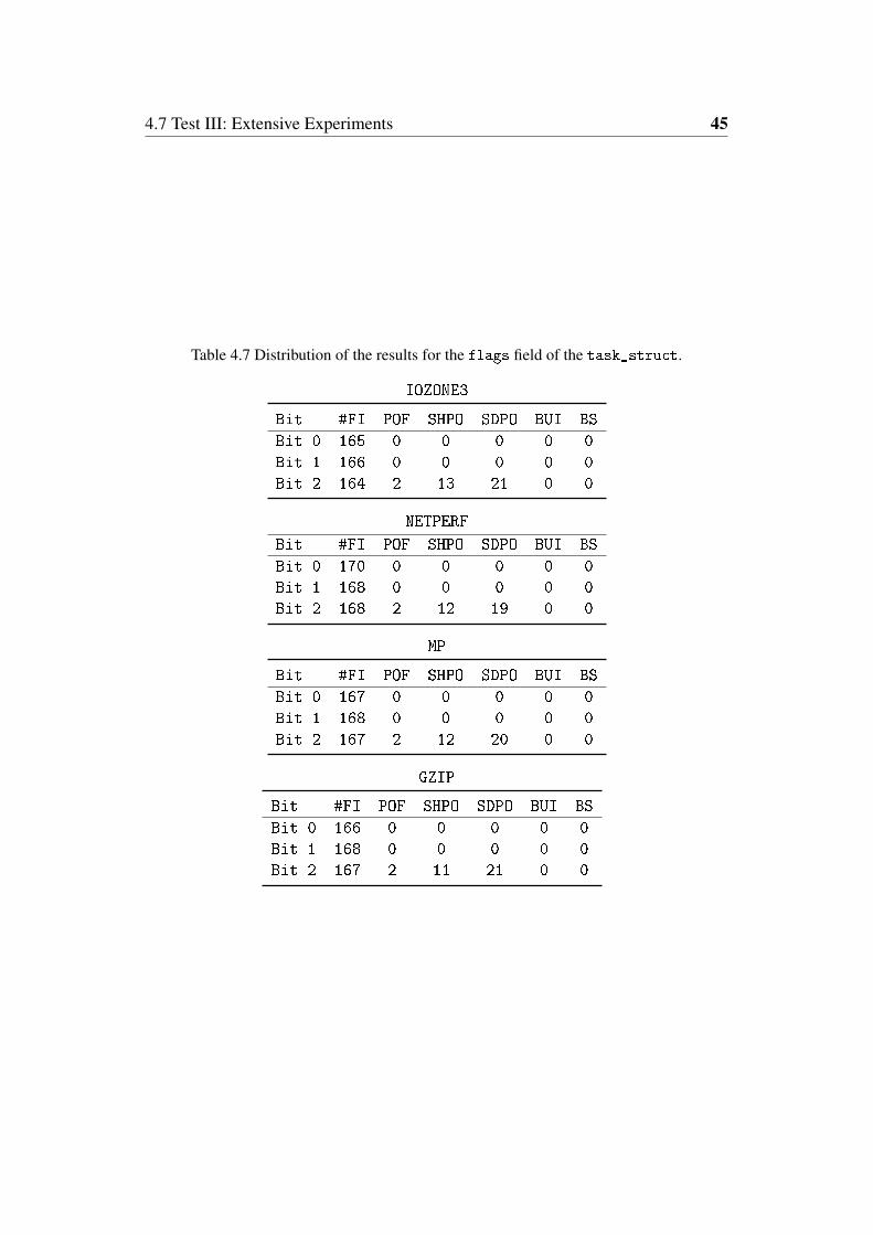
4.7 Test III: Extensive Experiments 45
Table 4.7 Distribution of the results for the flags field of the task_struct.
IOZONE3
Bit #FI POF SHPO SDPO BUI BS
Bit 0 165 0 0 0 0 0
Bit 1 166 0 0 0 0 0
Bit 2 164 2 13 21 0 0
NETPERF
Bit #FI POF SHPO SDPO BUI BS
Bit 0 170 0 0 0 0 0
Bit 1 168 0 0 0 0 0
Bit 2 168 2 12 19 0 0
MP
Bit #FI POF SHPO SDPO BUI BS
Bit 0 167 0 0 0 0 0
Bit 1 168 0 0 0 0 0
Bit 2 167 2 12 20 0 0
GZIP
Bit #FI POF SHPO SDPO BUI BS
Bit 0 166 0 0 0 0 0
Bit 1 168 0 0 0 0 0
Bit 2 167 2 11 21 0 0
46 Experimental Results
In all the tables, the term #FI corresponds to the number of fault injections carriedout. Table 4.5 shows the experiments in the mutex semaphores. The noxious effectsare almost equally distributed independently of the kind of load given to the system;11.56% of the injected faults in the mutex semaphores hanged the system during thepower off (considering only the most and least significant bits), the most commonerror message for this failure on the power off screen was the time out of a process.Additional analysis of the error messages suggests that these kinds of errors messagesare common when tasks are held in endless loop scenarios. These faults inhibit themutex function to allow programs to continue to a critical section of code, limitingthe ability of this process to complete its task and to exit, resulting in a deadlockscenario. Additionally, the computer is hanged during the reboot by processes otherthan the benchmark. In relation to faults injected into bit 1 no noxious effects wereobserved. Whereas, the faults made into the most significant bit (bit 31) presentedeffects comparable to the least significant bit.
Table 4.6 displays the results of the experiments that made faults into the statefield of the task_struct. Once again, changes to the least significant bit showedto be the most critical. Given that the least significant bit changes into a valid state,therefore, providing a valid option for the scheduler to process corrupt informationin the state field without triggering any kind of recovery mechanism. 26.34% offaults in the bit 0 resulted in a failure. A single fault injected made into the bit 1,while the state of this task was TASK_RUNNING, so the fault injection resulted in avalue signalling to the scheduler TASK_UNINTERRUPTIBLE state, also providing acorrupted value.
Table 4.7 shows the distribution of the effects in the experiments involving faultinjections into the flags field. In this case, bit indicating the PF_EXITING flag wasthe only critical one. This bit incurred in noxious effects in 20.57% of faults injected.The other two bits corresponding to undefined values did not present any effects.
4.7.4 Effects on Performance
IOzone3 and Netperf benchmarks provide exact metrics in performance, and theseregistered significant degradation.
4.7 Test III: Extensive Experiments 47
IOzone3
The IOzone3 benchmark was executed with options that would register performancein writing, reading, rewriting, writing backwards and writing in random order op-erations. Figure 4.4 shows two particular scenarios in which the performance wasaffected because of the faults. In both graphs, the performance is measured in I/Ooperations per second in the vertical axis. While the horizontal axis denotes eachindividual test performed in order. In the case of the top graph, the lower the numberis, then the closer the process being injected upon is to the core of the kernel. Giventhat init has the value 1, each following process goes to higher and higher layers ofthe operating system. This graph shows the effects of the faults injected into the Bit 0in the flags field of the task_struct. Finally, the red horizontal line correspondsto the mean of 20 golden experiments (i.e., the execution without fault injection).From this graph we can infer that a fault affecting a core process of the operatingsystem would have higher performance degradation than a fault affecting processescloser to the user space. This was true to all the faults in the state and flag fields.

48 Experimental Results
Fig. 4.4 Performance of different experiments performed with IOzone3 Benchmark. The topgraph corresponds to faults affecting bit 0 in the flags field of task_truct. The bottomgraph corresponds to faults affecting bit 0 in the Mutex semaphores.
Considering the second graph in Figure 4.4, the horizontal axis represents eachindividual mutex semaphore in order as extracted from the proc file system. In thiscase almost all the fault injections in the mutex semaphores presented a performancedegradation. The average of the degradation was around 48.8% (about 88,000operations per second compared to 173,000 for the golden experiment); only theswapon_mutex (number 58 in the graph) presented no degradation in its performance,but this is most likely because no swap operation was performed by the system duringthe test. Note that for the bottom graph there is no correlation between the numberof the experiment and PID, since each experiment corresponds to a specific Mutex.So, we can state that in relation to the I/O bounded processes, faults in the mutexsemaphores result in a significant performance degradation.
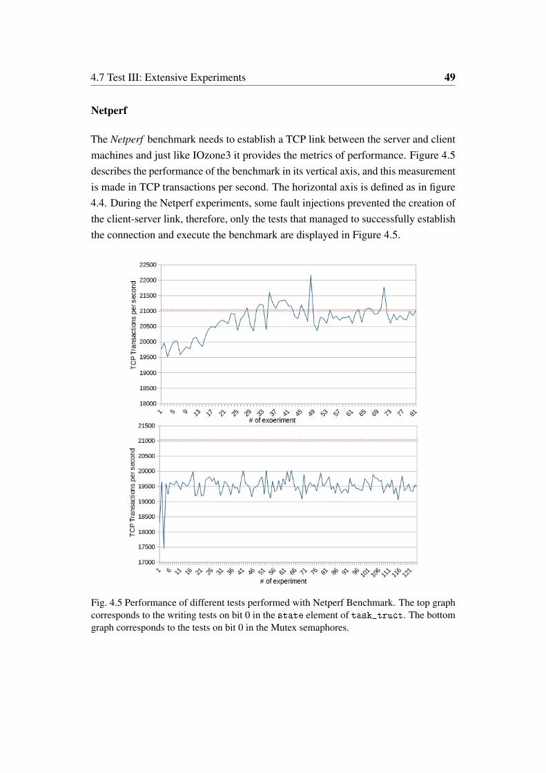
4.7 Test III: Extensive Experiments 49
Netperf
The Netperf benchmark needs to establish a TCP link between the server and clientmachines and just like IOzone3 it provides the metrics of performance. Figure 4.5describes the performance of the benchmark in its vertical axis, and this measurementis made in TCP transactions per second. The horizontal axis is defined as in figure4.4. During the Netperf experiments, some fault injections prevented the creation ofthe client-server link, therefore, only the tests that managed to successfully establishthe connection and execute the benchmark are displayed in Figure 4.5.
Fig. 4.5 Performance of different tests performed with Netperf Benchmark. The top graphcorresponds to the writing tests on bit 0 in the state element of task_truct. The bottomgraph corresponds to the tests on bit 0 in the Mutex semaphores.

50 Experimental Results
Table 4.8 Connection issues in Netperf experiments
Test #FI Connection Failures Percentage
state 504 12 2.38%
flags 506 11 2.18%
prio 502 16 3.18%
Mutex 966 128 13.25%
Taking in consideration the overall performance, once again in the task_structexperiments there is a significant performance loss in the lower PID numbers, andthen incrementing to normal performance levels in processes closer to the user-spacelevel. Again, the horizontal line (at value 21000) corresponds to the average value of20 golden experiments. Finally, on the subject of faults in the mutex semaphores,the overall performance loss was almost uniformly distributed with a degradation of7.6%
The occurrences of faults that prevented the benchmark to establish the client-server connection are described in Table 4.8. This failure was present with a higherfailure rate in experiments that made faults in the mutex semaphores, with a 13.25%of the fault injection manifesting these failures.

Chapter 5
Redundant Techniques for KernelData Structures
The concluding activity of the research was concentrated on adding redundancyto the Linux kernel. These efforts were made into hardening the mutex systemand the scheduler. In both cases information-software redundancy techniques wereused. The first solution proposed was to introduce a TMR-like approach to themutex semaphore, this would involve the triplication of the semaphore informationand a voter mechanism to detect and correct all faults. The second was an ErrorDetection And Correction (EDAC) method taking advantage of the state fielddefinition in the task_struct. Both proposed approaches have to be implementedwith local-thread duplication because we desire to provide a broad and generalsolution, and not exclude the machines that are not capable of multi-threading, andbecause the scheduler and the mutex are in constant use it is impossible to perform aProcess-level redundancy.
5.1 The Mutex Mechanism
The implementation of hardening techniques to the mutex semaphores system neededthe modifications of a handful of files, and among them mutex.h and mutex.c. Inmutex.h the mutex data structure is defined, alongside a couple of functions that man-age some aspects of mutex, such as __MUTEX_INITIALIZER and mutex_is_locked.In addition, all the functions implemented in the mutex system have their functions

52 Redundant Techniques for Kernel Data Structures
Fig. 5.1 Simplified diagram of the subsystems of the mutex system and their components.
prototypes defined in mutex.h. While in mutex.c, over 30 functions are definedwhich interact with the mutex semaphores. These functions can be divided into dif-ferent subsets depending on the kind of operations these functions perform. The firstset is the division between the lock and unlock functions: these functions can furtherbe sub-divided into fast-path and slow-path lock/unlock functions. Additionally,there is a subset of functions intended to manage the waiting lists while performingthe mutex lock and unlock operations. The mutex.c file also includes functions thatare meant to update fields in the context of the process control block whenever aprocess gains or relinquishes control of a resource in the machine. Other functionsevaluate the availability of these resources. Finally, there are functions used in theWait/Wound mutex system, designed to solve the situation in which more than onemutex is called by a process in order to avoid deadlock scenarios. A simplifiedgraphical representation of the different elements involved in the mutex system isshown in Fig. 5.1.
5.1.1 Fastpath and Slowpath Mutex Operations
The mutex semaphores have three possible distinct states; unlocked, locked andwith waiting list. The current state that the mutex holds will determine which kind
5.2 Hardening Implementation 53
of operation will be performed in order to lock or unlock the mutex. There aretwo different approaches implemented for this. Fastpath mutex lock or unlock andslowpath mutex lock or unlock. Mutex fastpath is executed when a transition from(or to) an unlock mutex status is made. Fastpath is has a smaller footprint thanslowpath because it doesn’t have to manage waiting the waiting for a mutex northe managment of the waiting list. The fastpath functions are an assembly macroto increase or decrease the count variable of the mutex. The fastpath function isdependant on the machine’s architecture. An example of a fastpath operation is thefollowing one:
__mutex_fastpath_lock(count, fail_fn)
In this example, count is the semaphore variable of the mutex structure. Whenthe value of count is 1, then the function changes it to 0. In any other case (0 ornegative values) the function fail_fn is called. fail_fn is always the slowpathversion of the lock operation,. This occurs in any scenario when the transition isinto a "mutex with a waiting list". All the fastpath functions are defined in assemblylanguage and are architecture dependent. While the slowpath operations are primarilydefined in C language with calls to the operating system’s generic atomic operations.A process performing a lock/unlock operation will always try to perform a fastpathoperation and if the operation fails (meaning that the mutex is not free) then it willperform a slowpath operation, the main difference of both operations is that slowpathoperation takes into consideration many more variables into consideration and possesmany more states when considering it as a state machine cycle. For instance only ina slowpath operation there is any interaction with the waiting list for the mutex in alock operation.
5.2 Hardening Implementation
In order to improve the dependability of the mutex data structures, a Triple-Modular-Redundancy (TMR) technique has been adopted and introduced into the source filesof the Linux kernel [49]. This approach modifies the definition of the mutex structurein mutex.h by adding two new count variables (named count1 and count2). Therole of these variables is to triplicate the information describing the current stateof the mutex semaphore. Every time that the mutex is acted upon, e.g., for lock,
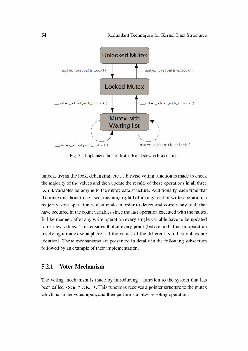
54 Redundant Techniques for Kernel Data Structures
Fig. 5.2 Implementation of fastpath and slowpath scenarios.
unlock, trying the lock, debugging, etc., a bitwise voting function is made to checkthe majority of the values and then update the results of these operations in all threecount variables belonging to the mutex data structure. Additionally, each time thatthe mutex is about to be used, meaning right before any read or write operation, amajority vote operation is also made in order to detect and correct any fault thathave occurred in the count variables since the last operation executed with the mutex.In like manner, after any write operation every single variable have to be updatedto its new values. This ensures that at every point (before and after an operationinvolving a mutex semaphore) all the values of the different count variables areidentical. These mechanisms are presented in details in the following subsectionfollowed by an example of their implementation.
5.2.1 Voter Mechanism
The voting mechanism is made by introducing a function to the system that hasbeen called vote_mutex(). This functions receives a pointer structure to the mutexwhich has to be voted upon, and then performs a bitwise voting operation.
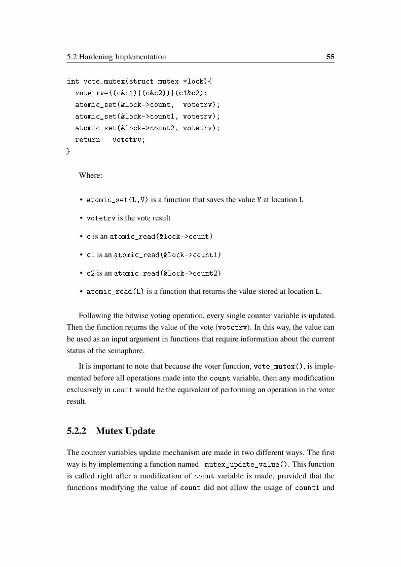
5.2 Hardening Implementation 55
int vote_mutex(struct mutex *lock){
votetrv=((c&c1)|(c&c2))|(c1&c2);
atomic_set(&lock->count, votetrv);
atomic_set(&lock->count1, votetrv);
atomic_set(&lock->count2, votetrv);
return votetrv;
}
Where:
• atomic_set(L,V) is a function that saves the value V at location L
• votetrv is the vote result
• c is an atomic_read(&lock->count)
• c1 is an atomic_read(&lock->count1)
• c2 is an atomic_read(&lock->count2)
• atomic_read(L) is a function that returns the value stored at location L.
Following the bitwise voting operation, every single counter variable is updated.Then the function returns the value of the vote (votetrv). In this way, the value canbe used as an input argument in functions that require information about the currentstatus of the semaphore.
It is important to note that because the voter function, vote_mutex(), is imple-mented before all operations made into the count variable, then any modificationexclusively in count would be the equivalent of performing an operation in the voterresult.
5.2.2 Mutex Update
The counter variables update mechanism are made in two different ways. The firstway is by implementing a function named mutex_update_value(). This functionis called right after a modification of count variable is made, provided that thefunctions modifying the value of count did not allow the usage of count1 and

56 Redundant Techniques for Kernel Data Structures
count2 directly: this is common for architecture dependant functions. This functionis defined as follows.
void mutex_update_value(struct mutex *lock){
atomic_set(&lock->count1,
atomic_read(&lock->count));
atomic_set(&lock->count2,
atomic_read(&lock->count));
}
This function was implemented immediately after every function that does notsupport operations over count1 and count2. mutex_update_value() reads thevalue of count and updates it directly into count1 and count2.
The second way is by means of additional identical functions that operate withthe count variable using the other two newly introduced variables. This kind ofupdate mechanism is implemented when there are no limitations to the operationover count1 and count2: this is particularly true when performing logic operations.
5.2.3 Implementation Examples
An example of the application of the voter and the first update mechanism can beseen in the following example.
void __sched mutex_lock(struct mutex *lock)
{
might_sleep();
vote_mutex(lock);
/*
* The locking fastpath is the
* 1->0 transition from
* 'unlocked' into 'locked' state.
*/
__mutex_fastpath_lock(&lock->count, __mutex_lock_slowpath);
mutex_update_value(lock);
mutex_set_owner(lock);

5.2 Hardening Implementation 57
}
In the presented example, it is possible to observe the mutex_lock function.The voter is used right before __mutex_fastpath_lock because this function willread the value of the mutex lock and then decide whether to execute a fastpath ora slowpath lock. During __mutex_fastpath_lock a decision is made to decreasethe value of count from 1 to 0 or to call the function __mutex_lock_slowpath de-pending on the value of count. Following the decision, it is necessary to implementmutex_update_value(), independent of the decision made by __mutex_fastpa
th_lock to run slowpath or not, the value of count has changed, and given that__mutex_lock_slowpath is a long process, it is not efficient to triplicate its execu-tion due to the excessive overhead it would produce.
An example of the second update mechanism can be seen in the following lineextracted from the function __mutex_lock_common:
static __always_inline int __sched
__mutex_lock_common(struct mutex *lock, long state, unsigned int
subclass, struct lockdep_map *nest_lock, unsigned long ip,
struct ww_acquire_ctx *ww_ctx, const bool use_ww_ctx)
{
...
for (;;) {
...
votetrv = vote_mutex(lock);
if ((votetrv >= 0 ) &&
(atomic_xchg(&lock->count, -1) == 1)
&&
(atomic_xchg(&lock->count1, -1) == 1)
&&
(atomic_xchg(&lock->count2, -1) == 1))
{
break;
}
...

58 Redundant Techniques for Kernel Data Structures
In this example atomic_xchg saves the value -1 into count variables and thenreturns the previous values of the count variables in order to make a decision.Because atomic logic operation are being used, it is more efficient to implement thisatomic operation in every single one of our custom count variables.
5.3 Experimental Results
In order to evaluate the effectiveness of the proposed solution, a series of experimentswere conducted.
5.3.1 Experimental Set-up
Four distinctive scenarios were considered for this experimental campaign: allexperiments consisted in evaluating the performance of different benchmarks runningin the Linux kernel. Two different operating systems were used in the tests: thefirst was a stable version of the Linux kernel running version 4.2 and the secondwas a custom robust version of kernel 4.2 which used the modifications previouslydiscussed in this chapter. Additionally, some versions of the experiments had a singlebit flip fault injected in memory using the fault injector described in chapter 3. Thescenarios considered are the following:
• Golden Experiment (a): The stable version of the Linux kernel running thebenchmarks and providing a reference performance value.
• Robust system (b): Evaluation of the impact caused by the robustness mod-ifications made to the kernel in terms of performance of the benchmarksprograms.
• Control FI (c): Equivalent to (a) with the difference that a single bit flipoperation is performed at a random time during the operation of the benchmarkprogram.
• Robust Evaluation (d): Equivalent to (b) with the difference that a singlebit flip operation is performed at a random time during the operation of thebenchmark program.
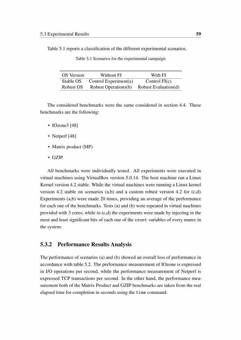
5.3 Experimental Results 59
Table 5.1 reports a classification of the different experimental scenarios.
Table 5.1 Scenarios for the experimental campaign
OS Version Without FI With FIStable OS Control Experiment(a) Control FI(c)Robust OS Robust Operations(b) Robust Evaluation(d)
The considered benchmarks were the same considered in section 4.4. Thesebenchmarks are the following:
• IOzone3 [48]
• Netperf [48]
• Matrix product (MP)
• GZIP.
All benchmarks were individually tested. All experiments were executed invirtual machines using VirtualBox version 5.0.14. The host machine ran a LinuxKernel version 4.2 stable. While the virtual machines were running a Linux kernelversion 4.2 stable on scenarios (a,b) and a custom robust version 4.2 for (c,d).Experiments (a,b) were made 20 times, providing an average of the performancefor each one of the benchmarks. Tests (a) and (b) were repeated in virtual machinesprovided with 3 cores; while in (c,d) the experiments were made by injecting in themost and least significant bits of each one of the count variables of every mutex inthe system.
5.3.2 Performance Results Analysis
The performance of scenarios (a) and (b) showed an overall loss of performance inaccordance with table 5.2. The performance measurement of IOzone is expressedin I/O operations per second, while the performance measurement of Netperf isexpressed TCP transactions per second. In the other hand, the performance mea-surement both of the Matrix Product and GZIP benchmarks are taken from the realelapsed time for completion in seconds using the time command.
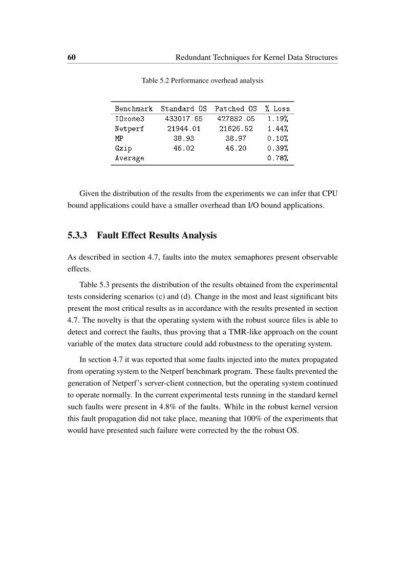
60 Redundant Techniques for Kernel Data Structures
Table 5.2 Performance overhead analysis
Benchmark Standard OS Patched OS % Loss
IOzone3 433017.65 427882.05 1.19%
Netperf 21944.01 21626.52 1.44%
MP 38.93 38.97 0.10%
Gzip 46.02 46.20 0.39%
Average 0.78%
Given the distribution of the results from the experiments we can infer that CPUbound applications could have a smaller overhead than I/O bound applications.
5.3.3 Fault Effect Results Analysis
As described in section 4.7, faults into the mutex semaphores present observableeffects.
Table 5.3 presents the distribution of the results obtained from the experimentaltests considering scenarios (c) and (d). Change in the most and least significant bitspresent the most critical results as in accordance with the results presented in section4.7. The novelty is that the operating system with the robust source files is able todetect and correct the faults, thus proving that a TMR-like approach on the countvariable of the mutex data structure could add robustness to the operating system.
In section 4.7 it was reported that some faults injected into the mutex propagatedfrom operating system to the Netperf benchmark program. These faults prevented thegeneration of Netperf’s server-client connection, but the operating system continuedto operate normally. In the current experimental tests running in the standard kernelsuch faults were present in 4.8% of the faults. While in the robust kernel versionthis fault propagation did not take place, meaning that 100% of the experiments thatwould have presented such failure were corrected by the the robust OS.
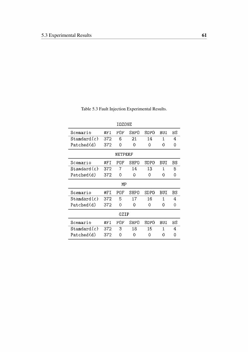
5.3 Experimental Results 61
Table 5.3 Fault Injection Experimental Results.
IOZONE
Scenario #FI POF SHPO SDPO BUI BS
Standard(c) 372 6 21 14 1 4
Patched(d) 372 0 0 0 0 0
NETPERF
Scenario #FI POF SHPO SDPO BUI BS
Standard(c) 372 7 14 13 1 5
Patched(d) 372 0 0 0 0 0
MP
Scenario #FI POF SHPO SDPO BUI BS
Standard(c) 372 5 17 16 1 4
Patched(d) 372 0 0 0 0 0
GZIP
Scenario #FI POF SHPO SDPO BUI BS
Standard(c) 372 3 18 15 1 4
Patched(d) 372 0 0 0 0 0
62 Redundant Techniques for Kernel Data Structures
5.4 Process Synchronisation
As described in chapter 2, the scheduler is the entity that is responsible for synchro-nising and switching from one process to the next. Additionally, in sections 4.6 and4.7 the susceptibility to faults in the following fields of this data structure has beendemonstrated:
• state
• thread_info->flags
• prio
All these fields contained bits that proved to be critical as far as dependability isconsidered, therefore a redundant mechanism is needed in order to detect and correctfaults affecting these mechanisms.
5.4.1 Redundancy Method
This section focused in the possible implementation of an hardening approach basedin encoding of the information storage. This redundancy would be made to solvethe issues generated by faults in the state field of the task_struct [50]. Thisapproach is based in the duplication of information and the modification of theencoding mechanism of this variable so that it becomes possible to detect and correctthe faults.
As described in chapter 2, the state is the field that informs the scheduler whichis the current status of the process. This state is defined in a bitmap like manner,meaning that a value of one in each bit corresponds to a particular state. From theresults reported in section 4.6 and 4.7 most of the faults occurred when the faultmanaged to make the switch from one state to another valid state, rather than toan invalid state (a state not defined in the bit map). The possible states are definedas described in Figure 5.3. There are also other states that are defined as an or
operation between two or more single bit states. In Figure 5.3, we can observe theexample of EXIT_TRACE, being a state defined by 1 in two different columns. Allthe other multiple bit states are defined with the prefix TASK_ and then the followingnames: killable, stopped, traced, idle, normal, all and report.
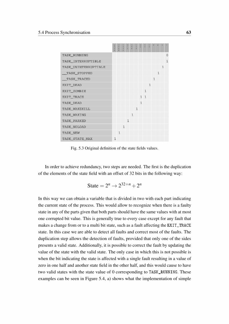
5.4 Process Synchronisation 63
Fig. 5.3 Original definition of the state fields values.
In order to achieve redundancy, two steps are needed. The first is the duplicationof the elements of the state field with an offset of 32 bits in the following way:
State = 2n → 232+n +2n
In this way we can obtain a variable that is divided in two with each part indicatingthe current state of the process. This would allow to recognize when there is a faultystate in any of the parts given that both parts should have the same values with at mostone corrupted bit value. This is generally true to every case except for any fault thatmakes a change from or to a multi bit state, such as a fault affecting the EXIT_TRACEstate. In this case we are able to detect all faults and correct most of the faults. Theduplication step allows the detection of faults, provided that only one of the sidespresents a valid state. Additionally, it is possible to correct the fault by updating thevalue of the state with the valid state. The only case in which this is not possible iswhen the bit indicating the state is affected with a single fault resulting in a value ofzero in one half and another state field in the other half, and this would cause to havetwo valid states with the state value of 0 corresponding to TASK_RUNNING. Theseexamples can be seen in Figure 5.4, a) shows what the implementation of simple
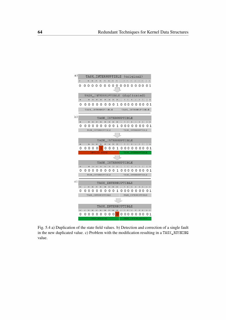
64 Redundant Techniques for Kernel Data Structures
Fig. 5.4 a) Duplication of the state field values. b) Detection and correction of a single faultin the new duplicated value. c) Problem with the modification resulting in a TASK_RUNNINGvalue.
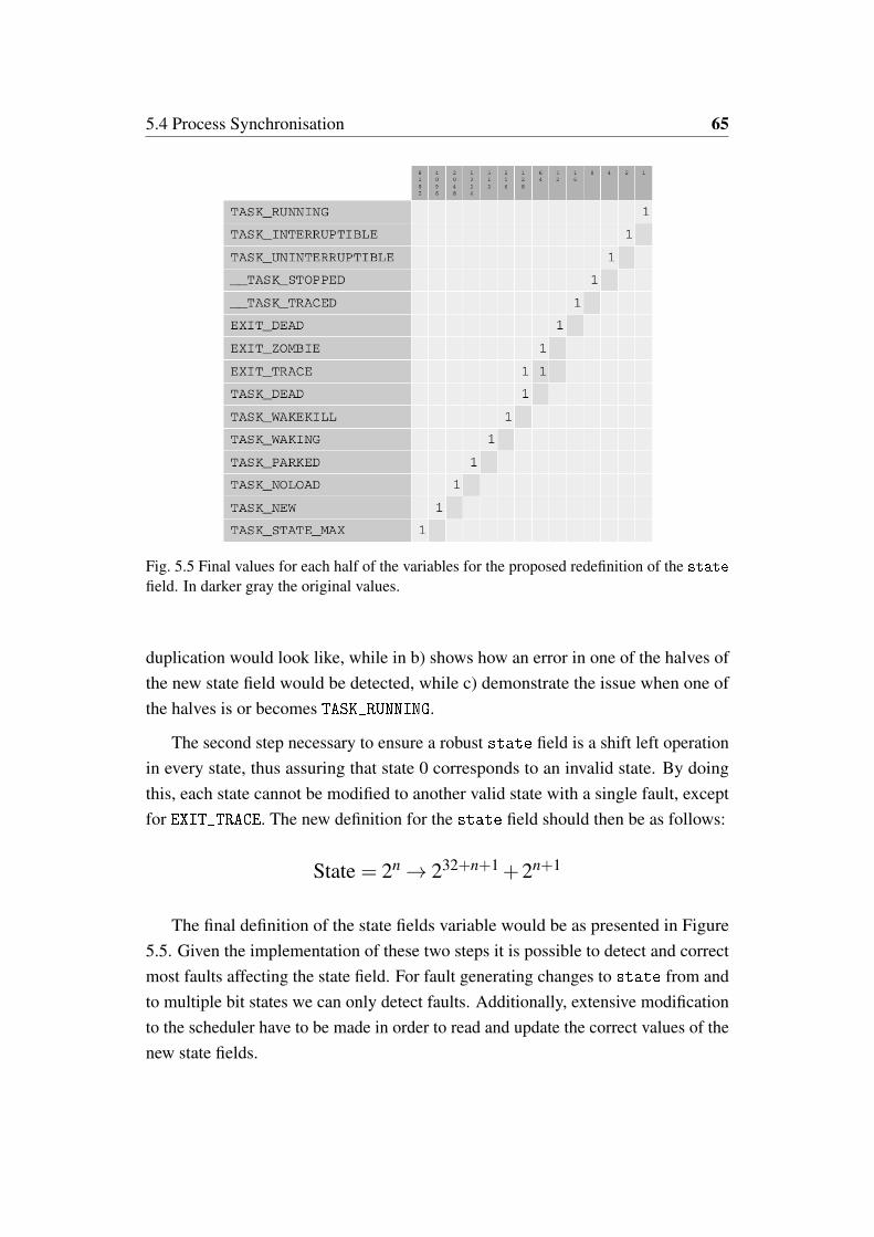
5.4 Process Synchronisation 65
Fig. 5.5 Final values for each half of the variables for the proposed redefinition of the statefield. In darker gray the original values.
duplication would look like, while in b) shows how an error in one of the halves ofthe new state field would be detected, while c) demonstrate the issue when one ofthe halves is or becomes TASK_RUNNING.
The second step necessary to ensure a robust state field is a shift left operationin every state, thus assuring that state 0 corresponds to an invalid state. By doingthis, each state cannot be modified to another valid state with a single fault, exceptfor EXIT_TRACE. The new definition for the state field should then be as follows:
State = 2n → 232+n+1 +2n+1
The final definition of the state fields variable would be as presented in Figure5.5. Given the implementation of these two steps it is possible to detect and correctmost faults affecting the state field. For fault generating changes to state from andto multiple bit states we can only detect faults. Additionally, extensive modificationto the scheduler have to be made in order to read and update the correct values of thenew state fields.
Chapter 6
Conclusions
This research project had two main objectives, the first is to evaluate the effectsof faults in the different kernel data structures, and the second objective is to addredundancy techniques to these structures.
The first objective was achieved, and the proposed fault injection module provedto be capable of generating faults in a diverse number of elements in the kernel,demonstrating that faults affecting these data structures are critical as far as depend-ability is considered. In theory KITO should be able to inject transient faults in anymemory element of the kernel space of the operating system.
During the experimental campaigns, it was proven that faults in some elementsof the operating system can alter the operation of the operating system and in somecases also the operation of the applications that depend in the support of the differentservices provided by the operating system.
In relation to the second objective, it was demonstrated that a TMR-like approachin the mutex data structure is capable of providing sufficient protection to detectand correct faults affecting the count variable of this structure. The experimentalevaluation of the proposed method for the hardening of the state field of the processcontrol block is still pending.
Overall the main objective of generating a fault injection method in order toevaluate the criticality of the kernel data structures was achieved. Meanwhile theprotection of the elements of the kernel that have been proven critical has beenpartially achieved.

67
From the implementation of this method in different versions of the Linux kernelit is clear that this method has a high degree of portability. It remains to be seenif this is true in the case of different operating systems based in the Linux kernelor micro kernel such as OSX, Solaris, QNX or Yocto project applications. OSX isthe operating system implemented in all Apple devices. While Solaris is a Linuxdistribution developed by Sun Microsystems which is commonly implemented innetwork servers. QNX is an Real Time Operating System (RTOS) for embeddedapplication, commonly found in automotive applications. Yocto Project is an opensource micro kernel developed from OpenEmbedded. Future activities could applythe proposed hardening techniques for these real-time and embedded systems, alongside exploring different data structures or memory elements of mechanisms thatwere not included in this research activity. Such elements include such as thethread_struct, RCU mechanisms, shared memory, call systems messages, etc.

References
[1] David Kaminski-Morrow. Qantas a330 upset inquiry considers cosmic particlestrike, 2009.
[2] NASA/JPL. Engineers diagnosing voyager 2 data system – update, 2010.
[3] Katholieke Universiteit Leuven, Universiteit Antwerpen, Universiteit Gent, Uni-versité Catholique de Louvain, Université de Liège, Université Libre de Brux-elles, and Vrije Universiteit Brussel. Bevoting study of electronic votingsystems, part i, 2007.
[4] M. Nicolaidis. Time redundancy based soft-error tolerance to rescue nanometertechnologies. In VLSI Test Symposium, 1999. Proceedings. 17th IEEE, pages86–94, 1999.
[5] Ravishankar K Iyer and Dong Tang. Experimental analysis of computer systemdependability. Prentice-Hall, Inc., 1996.
[6] J. Arlat, Y. Crouzet, J. Karlsson, P. Folkesson, E. Fuchs, and G.H. Leber.Comparison of physical and software-implemented fault injection techniques.Computers, IEEE Transactions on, 52(9):1115–1133, Sept 2003.
[7] IEC61508:1-7. Functional safety of electrical/electronic/programmable elec-tronic safety-related systems. Technical report, International ElectrotechnicalCommission•, 1998,2000.
[8] R. Svenningsson, J. Vinter, H. Eriksson, and M. Torngren. MODIFI: A MODel-Implemented Fault Injection Tool. In 29th International Conference, SAFE-COMP, pages 210–222, 2010.
[9] Henrique Madeira, Mário Rela, Francisco Moreira, and João Gabriel Silva.Rifle: A general purpose pin-level fault injector. In Dependable ComputingEDCC-1, pages 197–216. Springer, 1994.
[10] J. Karlsson, P. Liden, P. Dahlgren, R. Johansson, and U. Gunneflo. Using heavy-ion radiation to validate fault-handling mechanisms. Micro, IEEE, 14(1):8–23,Feb 1994.
References 69
[11] Johan Karlsson, Peter Folkesson, Jean Arlat, Yves Crouzet, Günther Leber, andJohannes Reisinger. Application of three physical fault injection techniquesto the experimental assessment of the mars architecture. In Dependable Com-puting for Critical Applications (Proc. Fifth IFIP Working Conf. DependableComputing for Critical Applications: DCCA-5), pages 267–287, 1998.
[12] M. Rebaudengo and M.S. Reorda. Evaluating the fault tolerance capabilities ofembedded systems via bdm. In VLSI Test Symposium, 1999. Proceedings. 17thIEEE, pages 452–457, 1999.
[13] R. Ramanarayanan, V. Degalahal, R. Krishnan, Jungsub Kim, V. Narayanan,Yuan Xie, M.J. Irwin, and K. Unlu. Modeling soft errors at the device and logiclevels for combinational circuits. Dependable and Secure Computing, IEEETransactions on, 6(3):202–216, July 2009.
[14] E. Jenn, J. Arlat, M. Rimen, J. Ohlsson, and J. Karlsson. Fault injection intovhdl models: the mefisto tool. In Fault-Tolerant Computing, 1994. FTCS-24.Digest of Papers, Twenty-Fourth International Symposium on, pages 66–75,June 1994.
[15] Mojtaba Ebrahimi, Abbas Mohammadi, Alireza Ejlali, and Seyed GhassemMiremadi. A fast, flexible, and easy-to-develop fpga-based fault injectiontechnique. Microelectronics Reliability, 54(5):1000 – 1008, 2014.
[16] Oana Boncalo, Alexandru Amaricai, Mihai Udrescu, and Mircea Vladutiu.Quantum circuit’s reliability assessment with vhdl-based simulated fault injec-tion. Microelectronics Reliability, 50(2):304 – 311, 2010.
[17] K.K. Goswami. Depend: a simulation-based environment for system leveldependability analysis. Computers, IEEE Transactions on, 46(1):60–74, Jan1997.
[18] P. Civera, L. Macchiarulo, M. Rebaudengo, M. Sonza Reorda, and M. Violante.Exploiting fpga-based techniques for fault injection campaigns on vlsi circuits.In Proceedings 2001 IEEE International Symposium on Defect and FaultTolerance in VLSI Systems, pages 250–258, 2001.
[19] P. Vanhauwaert, R. Leveugle, and P. Roche. A flexible sopc-based fault injectionenvironment. In 2006 IEEE Design and Diagnostics of Electronic Circuits andsystems, pages 190–195, April 2006.
[20] R. Leveugle, A. Calvez, P. Maistri, and P. Vanhauwaert. Statistical faultinjection: Quantified error and confidence. In 2009 Design, Automation Test inEurope Conference Exhibition, pages 502–506, April 2009.
[21] G.A. Kanawati, N.A. Kanawati, and J.A. Abraham. Ferrari: a flexible software-based fault and error injection system. Computers, IEEE Transactions on,44(2):248–260, Feb 1995.
70 References
[22] C. Giuffrida, A. Kuijsten, and A.S. Tanenbaum. Edfi: A dependable faultinjection tool for dependability benchmarking experiments. In DependableComputing (PRDC), 2013 IEEE 19th Pacific Rim International Symposium on,pages 31–40, Dec 2013.
[23] J. Carreira, H. Madeira, and J.G. Silva. Xception: a technique for the experi-mental evaluation of dependability in modern computers. Software Engineering,IEEE Transactions on, 24(2):125–136, 1998.
[24] J. Aidemark, J. Vinter, P. Folkesson, and J. Karlsson. Goofi: generic object-oriented fault injection tool. In Dependable Systems and Networks, 2001. DSN2001. International Conference on, pages 83–88, July 2001.
[25] J.A. Duraes and H.S. Madeira. Emulation of software faults: A field datastudy and a practical approach. Software Engineering, IEEE Transactions on,32(11):849–867, Nov 2006.
[26] Peter J. Denning. Fault tolerant operating systems. ACM Comput. Surv.,8(4):359–389, December 1976.
[27] Inhwan Lee and R.K. Iyer. Faults, symptoms, and software fault tolerance inthe tandem guardian90 operating system. In Fault-Tolerant Computing, 1993.FTCS-23. Digest of Papers., The Twenty-Third International Symposium on,pages 20–29, June 1993.
[28] G. Carrette. Crashme: Random Input Testing.http://people.delphiforums.com/gjc/crashme.html, 1998.
[29] Barton P Miller, Louis Fredriksen, and Bryan So. An empirical study of thereliability of unix utilities. Communications of the ACM, 33(12):32–44, 1990.
[30] N.P. Kropp, P.J. Koopman, and D.P. Siewiorek. Automated robustness testingof off-the-shelf software components. In Fault-Tolerant Computing, 1998.Digest of Papers. Twenty-Eighth Annual International Symposium on, pages230–239, June 1998.
[31] A. Albinet, J. Arlat, and J.-C. Fabre. Characterization of the impact of faultydrivers on the robustness of the linux kernel. In Dependable Systems andNetworks, 2004 International Conference on, pages 867–876, June 2004.
[32] K. Kanoun and L. Spainhower. Benchmarking the Operating System againstFaults Impacting Operating System Functions, pages 311–339. Wiley-IEEEPress, 2008.
[33] A. Holler, A. Krieg, T. Rauter, J. Iber, and C. Kreiner. Qemu-based faultinjection for a system-level analysis of software countermeasures against faultattacks. In Digital System Design (DSD), 2015 Euromicro Conference on,pages 530–533, Aug 2015.
References 71
[34] M. Kooli, P. Benoit, G. Di Natale, L. Torres, and V. Sieh. Fault injection toolsbased on virtual machines. In Reconfigurable and Communication-CentricSystems-on-Chip (ReCoSoC), 2014 9th International Symposium on, pages 1–6,May 2014.
[35] T. Jarboui, J. Arlat, Y. Crouzet, and K. Kanoun. Experimental analysis of theerrors induced into linux by three fault injection techniques. In Dependable Sys-tems and Networks, 2002. DSN 2002. Proceedings. International Conferenceon, pages 331–336, 2002.
[36] Alessandro Rubini and Jonathan Corbet. Linux device drivers. O’Reilly Media,Inc., 2001.
[37] Gianpiero Cabodi, Marco Murciano, and Massimo Violante. Boosting softwarefault injection for dependability analysis of real-time embedded applications.ACM Trans. Embed. Comput. Syst., 10(2):24:1–24:32, January 2011.
[38] Michael J. Wirthlin, Andrew M. Keller, Chase McCloskey, Parker Ridd, DavidLee, and Jeffrey Draper. Seu mitigation and validation of the leon3 softprocessor using triple modular redundancy for space processing. In Proceedingsof the 2016 ACM/SIGDA International Symposium on Field-ProgrammableGate Arrays, FPGA ’16, pages 205–214, New York, NY, USA, 2016. ACM.
[39] F. Lima Kastensmidt, L. Sterpone, L. Carro, and M. Sonza Reorda. On theoptimal design of triple modular redundancy logic for sram-based fpgas. InProceedings of the Conference on Design, Automation and Test in Europe -Volume 2, DATE ’05, pages 1290–1295, Washington, DC, USA, 2005. IEEEComputer Society.
[40] N. R. Saxena, C. W. D. Chang, K. Dawallu, J. Kohli, and P. Helland. Fault-tolerant features in the hal memory management unit. IEEE Transactions onComputers, 44(2):170–180, Feb 1995.
[41] C. Borchert, H. Schirmeier, and O. Spinczyk. Generic soft-error detection andcorrection for concurrent data structures. IEEE Transactions on Dependableand Secure Computing, 14(1):22–36, Jan 2017.
[42] P. Koopman and T. Chakravarty. Cyclic redundancy code (crc) polynomialselection for embedded networks. In International Conference on DependableSystems and Networks, 2004, pages 145–154, June 2004.
[43] Y. Brun, G. Edwards, J. Y. Bang, and N. Medvidovic. Smart redundancy fordistributed computation. In 2011 31st International Conference on DistributedComputing Systems, pages 665–676, June 2011.
[44] A.D. Velasco, B. Montrucchio, and M. Rebaudengo. Software-implementedfault injection in operating system kernel mutex data structure. In Circuits andSystems (LASCAS), 2014 IEEE 5th Latin American Symposium on, pages 1–6,Feb 2014.
72 References
[45] A.D. Velasco, B. Montrucchio, and M. Rebaudengo. Fault injection in theprocess descriptor of a unix-based operating system. In Defect and Fault Toler-ance in VLSI and Nanotechnology Systems (DFT), 2014 IEEE InternationalSymposium on, pages 281–286, Oct 2014.
[46] A.D. Velasco, B. Montrucchio, and M. Rebaudengo. Kito tool: A fault injec-tion environment in linux kernel data structures. Microelectronics Reliability,60:153–162, 2016.
[47] Abraham Silberschatz, Peter B Galvin, and Greg Gagne. Operating systemconcepts. Addison-Wesley, 1998.
[48] Eduardo Ciliendo and Takechika Kunimasa. Linux performance and tuningguidelines. IBM, International Technical Support Organization, 2007.
[49] A. D. Velasco, B. Montrucchio, and M. Rebaudengo. Tmr technique for mutexkernel data structures. In 2017 18th IEEE Latin American Test Symposium(LATS), pages 1–6, March 2017.
[50] A. D. Velasco, B. Montrucchio, and M. Rebaudengo. Hardening approach forthe scheduler’s kernel data structures. In 13th Workshop on Dependability andFault Tolerance, April 2017.

Appendix A
The KITO Module
#include <linux/module.h>
#include <linux/moduleparam.h>
#include <linux/kernel.h>
#include <linux/init.h>
#include <linux/stat.h>
#include <asm/bitops.h>
#include <linux/hrtimer.h>
#include <linux/ktime.h>
#include <linux/kallsyms.h>
#include <linux/string.h>
#include <linux/binfmts.h>
#include <linux/personality.h>
#include <linux/sched.h>
MODULE_LICENSE("GPL");
MODULE_AUTHOR("B. Montrucchio, M. Rebaudengo, A. Velasco");
//static unsigned long Baddress;
//------ definition of loading parameters ------
static unsigned long address, timensecs = 0;
const char* sym = "null_empty";
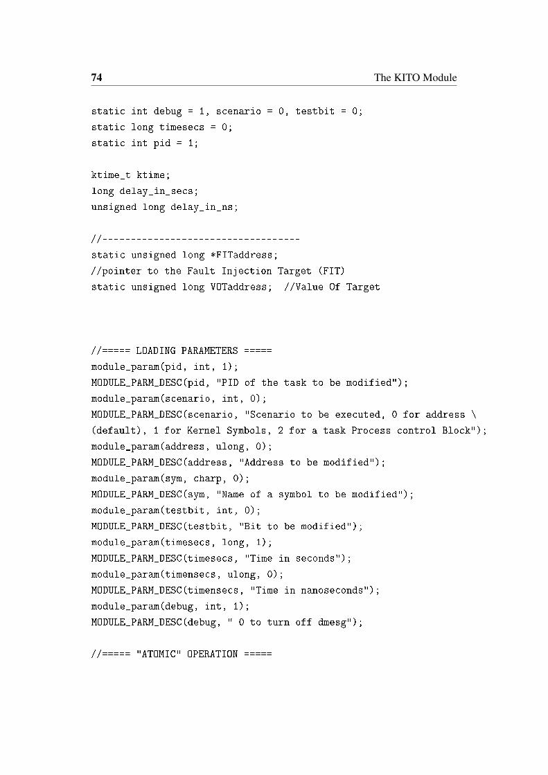
74 The KITO Module
static int debug = 1, scenario = 0, testbit = 0;
static long timesecs = 0;
static int pid = 1;
ktime_t ktime;
long delay_in_secs;
unsigned long delay_in_ns;
//-----------------------------------
static unsigned long *FITaddress;
//pointer to the Fault Injection Target (FIT)
static unsigned long VOTaddress; //Value Of Target
//===== LOADING PARAMETERS =====
module_param(pid, int, 1);
MODULE_PARM_DESC(pid, "PID of the task to be modified");
module_param(scenario, int, 0);
MODULE_PARM_DESC(scenario, "Scenario to be executed, 0 for address \
(default), 1 for Kernel Symbols, 2 for a task Process control Block");
module_param(address, ulong, 0);
MODULE_PARM_DESC(address, "Address to be modified");
module_param(sym, charp, 0);
MODULE_PARM_DESC(sym, "Name of a symbol to be modified");
module_param(testbit, int, 0);
MODULE_PARM_DESC(testbit, "Bit to be modified");
module_param(timesecs, long, 1);
MODULE_PARM_DESC(timesecs, "Time in seconds");
module_param(timensecs, ulong, 0);
MODULE_PARM_DESC(timensecs, "Time in nanoseconds");
module_param(debug, int, 1);
MODULE_PARM_DESC(debug, " 0 to turn off dmesg");
//===== "ATOMIC" OPERATION =====

75
static struct hrtimer hr_timer;
enum hrtimer_restart fi_hrtimer_callback( struct hrtimer *timer )
{
change_bit(testbit,FITaddress); //change of the bit
if (debug == 1 )
{
VOTaddress = *FITaddress;
printk(KERN_INFO "After the fault injection the value is %d\n", VOTaddress);
printk(KERN_INFO "=============================\n");
}
return HRTIMER_NORESTART;
}
//===== MODULE IN & OUT FUNCTIONS =====
//init of the kernel mod
static int __init chgbittest_init(void)
{
if (scenario == 0){ // If for modifying a particular Address in memory
if (address != 0)
{
FITaddress = address;
VOTaddress = *FITaddress;
if (debug == 1)
printk(KERN_INFO "The value of the loaded address is %lu\n", address);
printk(KERN_INFO "At first value is %d\n", VOTaddress);
printk(KERN_INFO "=============================\n");
}
else
{
printk(KERN_INFO "No loadable values given, cannot proceed\n");
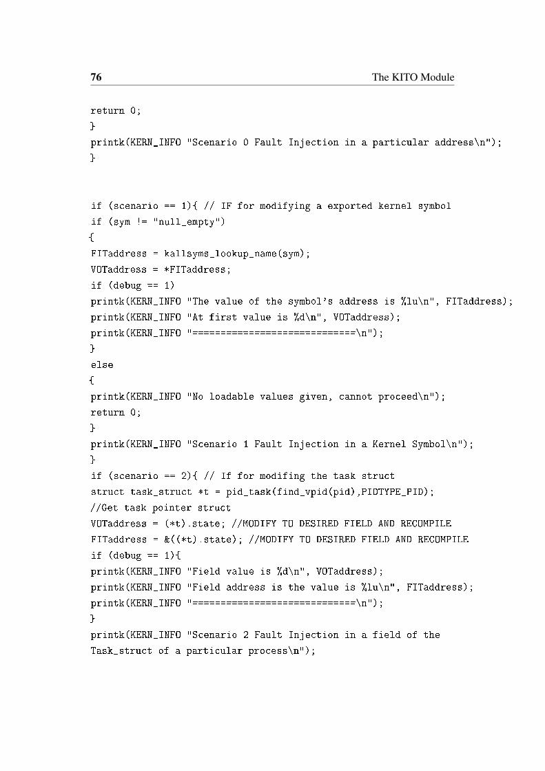
76 The KITO Module
return 0;
}
printk(KERN_INFO "Scenario 0 Fault Injection in a particular address\n");
}
if (scenario == 1){ // IF for modifying a exported kernel symbol
if (sym != "null_empty")
{
FITaddress = kallsyms_lookup_name(sym);
VOTaddress = *FITaddress;
if (debug == 1)
printk(KERN_INFO "The value of the symbol's address is %lu\n", FITaddress);
printk(KERN_INFO "At first value is %d\n", VOTaddress);
printk(KERN_INFO "=============================\n");
}
else
{
printk(KERN_INFO "No loadable values given, cannot proceed\n");
return 0;
}
printk(KERN_INFO "Scenario 1 Fault Injection in a Kernel Symbol\n");
}
if (scenario == 2){ // If for modifing the task struct
struct task_struct *t = pid_task(find_vpid(pid),PIDTYPE_PID);
//Get task pointer struct
VOTaddress = (*t).state; //MODIFY TO DESIRED FIELD AND RECOMPILE
FITaddress = &((*t).state); //MODIFY TO DESIRED FIELD AND RECOMPILE
if (debug == 1){
printk(KERN_INFO "Field value is %d\n", VOTaddress);
printk(KERN_INFO "Field address is the value is %lu\n", FITaddress);
printk(KERN_INFO "=============================\n");
}
printk(KERN_INFO "Scenario 2 Fault Injection in a field of the
Task_struct of a particular process\n");

77
}
printk(KERN_INFO "=============================\n");
//===== TIMER =====
delay_in_secs = timesecs; // set the delay on seconds
delay_in_ns = timensecs; // set the delay on nseconds
ktime = ktime_set( delay_in_secs, delay_in_ns );
// set the timer with the values of delays
hrtimer_init( &hr_timer, CLOCK_MONOTONIC, HRTIMER_MODE_REL );
//init timer
hr_timer.function = &fi_hrtimer_callback;
// function to exec after timer ends
if (debug == 1){
printk(KERN_INFO "timer set to %ld s %lu ns at the CPU time %lu\n",\
delay_in_secs,delay_in_ns, jiffies );
}
hrtimer_start( &hr_timer, ktime, HRTIMER_MODE_REL );
//timer start
return 0;
}
static void __exit chgbittest_exit(void)
{
printk(KERN_INFO "FIN\n");
return;
}
module_init(chgbittest_init);
module_exit(chgbittest_exit);

Appendix B
Doctoral Period’s Publications
2014
Software-implemented Fault Injection in Operating System Kernel Mutex DataStructureB. Montrucchio, M. Rebaudengo, A. Velasco5th IEEE Latin American Symposium on Circuits and Systems, Santiago, Chile,February 25-28, 2014
Fault Injection in the Process Descriptor of a Unix-based Operating SystemB. Montrucchio, M. Rebaudengo, A. VelascoIEEE International Symposium on Defect and Fault Tolerance in VLSI and Nan-otechnology Systems, Amsterdam, Netherlands , 1-3 October 2014
2015
On gait recognition with smartphone accelerometerR. Ferrero, F. Gandino, B. Montrucchio, M. Rebaudengo, A Velasco, I. Benkhelifa4th Mediterranean Conference on Embedded Computing (MECO-2015), Budva,Montenegro, 14-18 June, 2015
79
On the design of distributed air quality monitoring systemsR. Ferrero, F. Gandino, B. Montrucchio, M. Rebaudengo, A Velasco11th International Conference of Computational Methods in Sciences and Engineer-ing (ICCMSE 2015), Atene, Greece, 20-23 March 2015
2016
KITO tool: A fault injection environment in Linux kernel data structuresB. Montrucchio, M. Rebaudengo, A. VelascoMicroelectronics Reliability, vol. 60, pp. 153-162, 2016
A mobile and low-cost system for environmental monitoring: a case studyR. Ferrero, F. Gandino, B. Montrucchio, M. Rebaudengo, A VelascoSensors, vol. 16 n. 5, pp. 1-17, 2016
2017
TMR Technique for Mutex Kernel Data StructuresB. Montrucchio, M. Rebaudengo, A. Velasco18th IEEE Latin American Test Symposium, Bogota, Colombia, 13-15 March 2017
Hardening Approach for the Scheduler’s Kernel Data StructuresB. Montrucchio, M. Rebaudengo, A. Velasco13th Workshop on Dependability and Fault Tolerance, Wien, Austria, 3-6 April 2017


![Politecnico di Torino Porto Institutional Repository · Porto Institutional Repository [Proceeding] Installation of a Concentrated Solar Power System for the Thermal Needs of Buildings](https://static.fdocuments.net/doc/165x107/6105840c90be8f0f76221ba7/politecnico-di-torino-porto-institutional-repository-porto-institutional-repository.jpg)


