Polaris: Getting Accurate Indoor Orientations for Mobile ...
7
Carnegie Mellon University From the SelectedWorks of Zheng Sun February 2012 Polaris: Geing Accurate Indoor Orientations for Mobile Devices Using Ubiquitous Visual Paerns on Ceilings Contact Author Start Your Own SelectedWorks Notify Me of New Work Available at: hp://works.bepress.com/zhengs/9
Transcript of Polaris: Getting Accurate Indoor Orientations for Mobile ...
Carnegie Mellon University
From the SelectedWorks of Zheng Sun
February 2012
Polaris: Getting Accurate Indoor Orientations forMobile Devices Using Ubiquitous Visual Patternson Ceilings
ContactAuthor
Start Your OwnSelectedWorks
Notify Meof New Work
Available at: http://works.bepress.com/zhengs/9

Polaris: Getting Accurate Indoor Orientations for MobileDevices Using Ubiquitous Visual Patterns on Ceilings
1Zheng Sun, 1Aveek Purohit, 2Shijia Pan, 1Frank Mokaya, 3Raja Bose, and 1Pei Zhang1Electrical and Computer Engineering, Carnegie Mellon University
2Computer Science and Technology, University of Science and Technology of China3Nokia Research Center, Palo Alto
{zhengs, apurohit, peizhang, fmokaya}@cmu.edu, {shijia.pan}@gmail.com, {raja.bose}@nokia.com
ABSTRACTUbiquitous computing applications commonly use digital compasssensors to obtain orientation of a device relative to the magneticnorth of the earth. However, these compass readings are alwaysprone to significant errors in indoor environments due to presenceof metallic objects in close proximity. Such errors can adverselyaffect the performance and quality of user experience of theappli-cations utilizing digital compass sensors.
In this paper, we propose Polaris, a novel approach to provide re-liable orientation information for mobile devices in indoor environ-ments. Polaris achieves this by aggregating pictures of theceilingof an indoor environment and applies computer vision based pat-tern matching techniques to utilize them as orientation referencesfor correcting digital compass readings. To show the feasibility ofthe Polaris system, we implemented the Polaris system on mobiledevices, and field tested the system in multiple office buildings.Our results show that Polaris achieves 4.5◦ average orientation ac-curacy, which is about 3.5 times better than what can be achievedthrough sole use of raw digital compass readings.
Categories and Subject DescriptorsC.3 [Special-purpose and application-based systems]: Signal pro-cessing systems
General TermsAlgorithms, Design, Experimentation
KeywordsOrientation, digital compass, ceiling pictures
1. INTRODUCTIONDigital compass equipped mobile devices have become fairly
common now and are playing increasingly important roles in ubiq-uitous computing application domains, such as localization [1], ac-tivity recognition [4], photographing [12], and gaming [11].
A digital compass sensor provides the orientation of the devicerelative to the magnetic north of the earth. However, when used
Permission to make digital or hard copies of all or part of this work forpersonal or classroom use is granted without fee provided that copies arenot made or distributed for profit or commercial advantage and that copiesbear this notice and the full citation on the first page. To copy otherwise, torepublish, to post on servers or to redistribute to lists, requires prior specificpermission and/or a fee.HotMobile’12 February 28–29, 2012, San Diego, CA, USA.Copyright 2012 ACM 978-1-4503-1207-3 ...$10.00.
within indoor environments they suffer from significant errors, dueto the existence of metallic objects in close proximity.
To compensate for compass errors, previous work has exploreddifferent approaches, such as filtering [1], averaging [14], or in-tegrating compass readings with gyroscopes using Kalman Filters[8]. However, these approaches usually assume that the magneticinterference is low, and that a ‘correct’ initial compass readingcan be obtained, otherwise compass errors will accumulate quicklyover time. Hence, these approaches perform poorly in conditionswhere there is high magnetic interference.
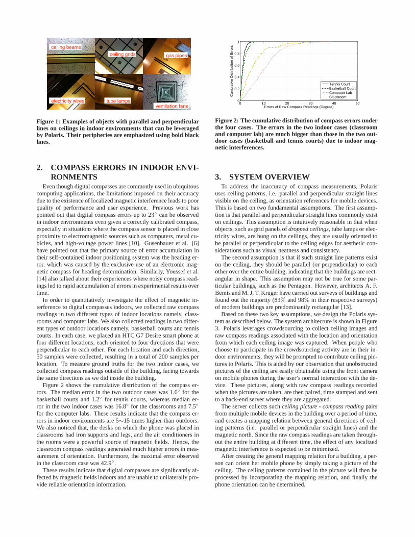
In this paper, we propose Polaris, a system that provides reli-able orientation information for mobile devices within indoor en-vironments. Our approach is based on an observation that indoorenvironments, such as classrooms, offices, and supermarkets, arehighly likely to have regular rectangular or square peripheries vis-ible on their ceilings. These objects include ceiling beams, panels,tube lamps, gas pipes, electricity wires, and ventilation fans. Theedges of these objects are usually straight, and are parallel or per-pendicular to the orientation of the buildings. Figure 1 shows someexamples of such patterns. Polaris uses these straight lines as ori-entation references for mobile devices to correct errors inmagneticcompass measurements. Therefore, in indoor environments havingsuch ceiling patterns, when a user wants to orient her mobilede-vice, she only needs to take a picture of the ceiling, and the orien-tation can then be inferred by incorporating both the visualpatternson the ceiling and the raw magnetic compass measurements.
As a preliminary effort, we implemented the Polaris system us-ing iPhones and HTC phones, and tested the system in multipleof-fice buildings. Our experimental results show that Polaris achieves4.5◦ average orientation accuracy, which is about 3.5 times betterthan what can be achieved using raw compass readings.
The key contributions of this paper are as follows:
1. We propose the novel idea of using ceiling features suchas parallel and perpendicular straight line edges of ceiling-mounted objects, to correct magnetic compass measurementsfor mobile devices.
2. We implemented the Polaris system using commercial off-the-shelf mobile phones, and show that Polaris achieves sig-nificantly better accuracy as compared to raw compass read-ings.
The rest of this paper is organized as follows. Section 2 moti-vates our work and Section 3 gives a system overview of Polaris.We describe the algorithms in Section 4 and provide evaluation re-sults in Section 5. Related work is shown in Section 6. Finally,Section 7 describes future work and Section 8 concludes the pa-per.
ceiling grids
ceiling beams
ventilation fans tube lamps
gas pipes
electricity wires
Figure 1: Examples of objects with parallel and perpendicularlines on ceilings in indoor environments that can be leveragedby Polaris. Their peripheries are emphasized using bold blacklines.
2. COMPASS ERRORS IN INDOOR ENVI-RONMENTS
Even though digital compasses are commonly used in ubiquitouscomputing applications, the limitations imposed on their accuracydue to the existence of localized magnetic interference leads to poorquality of performance and user experience. Previous work haspointed out that digital compass errors up to23◦ can be observedin indoor environments even given a correctly calibrated compass,especially in situations where the compass sensor is placedin closeproximity to electromagnetic sources such as computers, metal cu-bicles, and high-voltage power lines [10]. Gusenbauer et al. [6]have pointed out that the primary source of error accumulation intheir self-contained indoor positioning system was the heading er-ror, which was caused by the exclusive use of an electronic mag-netic compass for heading determination. Similarly, Youssef et al.[14] also talked about their experiences where noisy compass read-ings led to rapid accumulation of errors in experimental results overtime.
In order to quantitatively investigate the effect of magnetic in-terference to digital compasses indoors, we collected raw compassreadings in two different types of indoor locations namely,class-rooms and computer labs. We also collected readings in two differ-ent types of outdoor locations namely, basketball courts and tenniscourts. In each case, we placed an HTC G7 Desire smart phone atfour different locations, each oriented to four directionsthat wereperpendicular to each other. For each location and each direction,50 samples were collected, resulting in a total of 200 samples perlocation. To measure ground truths for the two indoor cases,wecollected compass readings outside of the building, facingtowardsthe same directions as we did inside the building.
Figure 2 shows the cumulative distribution of the compass er-rors. The median error in the two outdoor cases was 1.6◦ for thebasketball courts and 1.2◦ for tennis courts, whereas median er-ror in the two indoor cases was 16.8◦ for the classrooms and 7.5◦
for the computer labs. These results indicate that the compass er-rors in indoor environments are 5∼15 times higher than outdoors.We also noticed that, the desks on which the phone was placed inclassrooms had iron supports and legs, and the air conditioners inthe rooms were a powerful source of magnetic fields. Hence, theclassroom compass readings generated much higher errors inmea-surement of orientation. Furthermore, the maximal error observedin the classroom case was 42.9◦.
These results indicate that digital compasses are significantly af-fected by magnetic fields indoors and are unable to unilaterally pro-vide reliable orientation information.
0 10 20 30 40 500
0.2
0.4
0.6
0.8
1
Errors of Raw Compass Readings (Degree)
Cum
ulat
ive
Dis
trib
utio
n of
Err
ors
Tennis CourtBasketball CourtComputer LabClassroom
Figure 2: The cumulative distribution of compass errors underthe four cases. The errors in the two indoor cases (classroomand computer lab) are much bigger than those in the two out-door cases (basketball and tennis courts) due to indoor mag-netic interferences.
3. SYSTEM OVERVIEWTo address the inaccuracy of compass measurements, Polaris
uses ceiling patterns, i.e. parallel and perpendicular straight linesvisible on the ceiling, as orientation references for mobile devices.This is based on two fundamental assumptions. The first assump-tion is that parallel and perpendicular straight lines commonly existon ceilings. This assumption is intuitively reasonable in that whenobjects, such as grid panels ofdropped ceilings, tube lamps or elec-tricity wires, are hung on the ceilings, they are usually oriented tobe parallel or perpendicular to the ceiling edges for aesthetic con-siderations such as visual neatness and consistency.
The second assumption is that if such straight line patternsexiston the ceiling, they should be parallel (or perpendicular) to eachother over the entire building, indicating that the buildings are rect-angular in shape. This assumption may not be true for some par-ticular buildings, such as the Pentagon. However, architects A. F.Bemis and M. J. T. Kruger have carried out surveys of buildings andfound out the majority (83% and 98% in their respective surveys)of modern buildings are predominantly rectangular [13].
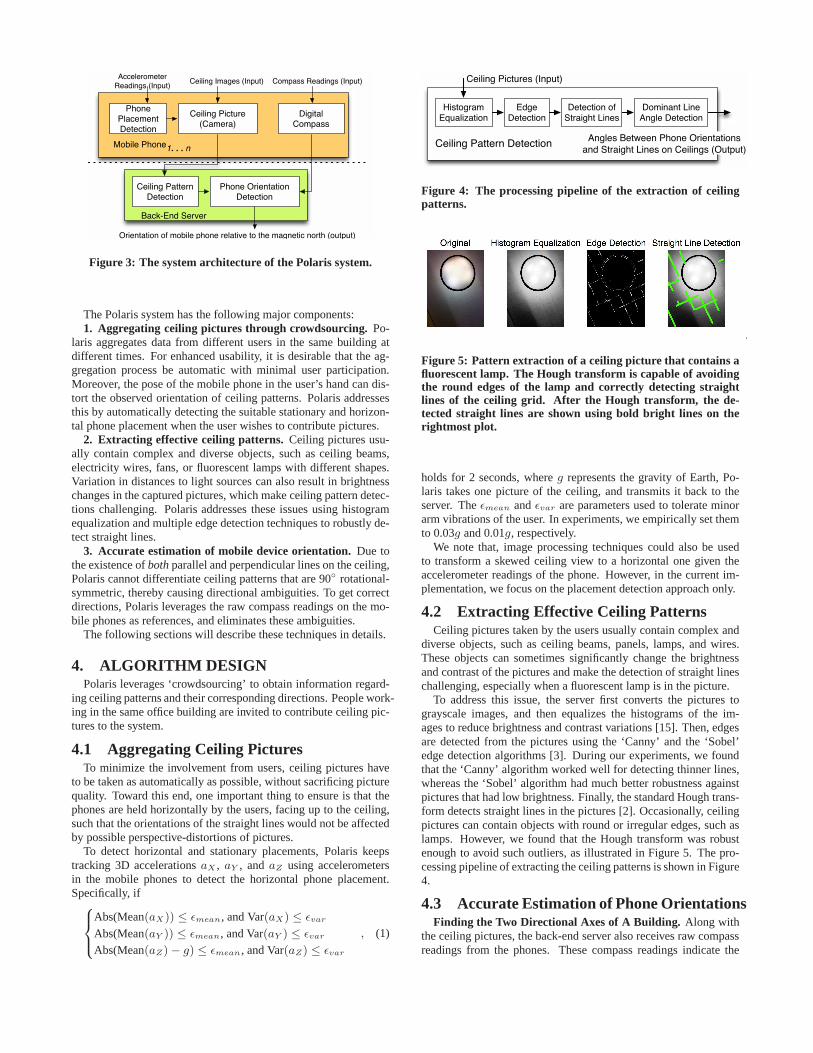
Based on these two key assumptions, we design the Polaris sys-tem as described below. The system architecture is shown in Figure3. Polaris leverages crowdsourcing to collect ceiling images andraw compass readings associated with the location and orientationfrom which each ceiling image was captured. When people whochoose to participate in the crowdsourcing activity are in their in-door environments, they will be prompted to contribute ceiling pic-tures to Polaris. This is aided by our observation that unobstructedpictures of the ceiling are easily obtainable using the front cameraon mobile phones during the user’s normal interaction with the de-vice. These pictures, along with raw compass readings recordedwhen the pictures are taken, are then paired, time stamped and sentto a back-end server where they are aggregated.
The server collects suchceiling picture - compass reading pairsfrom multiple mobile devices in the building over a period oftime,and creates a mapping relation between general directions of ceil-ing patterns (i.e. parallel or perpendicular straight lines) and themagnetic north. Since the raw compass readings are taken through-out the entire building at different time, the effect of any localizedmagnetic interference is expected to be minimized.
After creating the general mapping relation for a building,a per-son can orient her mobile phone by simply taking a picture of theceiling. The ceiling patterns contained in the picture willthen beprocessed by incorporating the mapping relation, and finally thephone orientation can be determined.
Mobile Phone1. . . n
Phone Placement Detection
Digital Compass
Ceiling Picture (Camera)
Back-End Server
Ceiling Pattern Detection
Phone Orientation Detection
Ceiling Images (Input) Compass Readings (Input)Accelerometer
Readings (Input)
Orientation of mobile phone relative to the magnetic north (output)
Figure 3: The system architecture of the Polaris system.
The Polaris system has the following major components:1. Aggregating ceiling pictures through crowdsourcing.Po-
laris aggregates data from different users in the same building atdifferent times. For enhanced usability, it is desirable that the ag-gregation process be automatic with minimal user participation.Moreover, the pose of the mobile phone in the user’s hand can dis-tort the observed orientation of ceiling patterns. Polarisaddressesthis by automatically detecting the suitable stationary and horizon-tal phone placement when the user wishes to contribute pictures.
2. Extracting effective ceiling patterns. Ceiling pictures usu-ally contain complex and diverse objects, such as ceiling beams,electricity wires, fans, or fluorescent lamps with different shapes.Variation in distances to light sources can also result in brightnesschanges in the captured pictures, which make ceiling pattern detec-tions challenging. Polaris addresses these issues using histogramequalization and multiple edge detection techniques to robustly de-tect straight lines.
3. Accurate estimation of mobile device orientation.Due tothe existence ofboth parallel and perpendicular lines on the ceiling,Polaris cannot differentiate ceiling patterns that are 90◦ rotational-symmetric, thereby causing directional ambiguities. To get correctdirections, Polaris leverages the raw compass readings on the mo-bile phones as references, and eliminates these ambiguities.
The following sections will describe these techniques in details.
4. ALGORITHM DESIGNPolaris leverages ‘crowdsourcing’ to obtain information regard-
ing ceiling patterns and their corresponding directions. People work-ing in the same office building are invited to contribute ceiling pic-tures to the system.
4.1 Aggregating Ceiling PicturesTo minimize the involvement from users, ceiling pictures have
to be taken as automatically as possible, without sacrificing picturequality. Toward this end, one important thing to ensure is that thephones are held horizontally by the users, facing up to the ceiling,such that the orientations of the straight lines would not beaffectedby possible perspective-distortions of pictures.
To detect horizontal and stationary placements, Polaris keepstracking 3D accelerationsaX , aY , andaZ using accelerometersin the mobile phones to detect the horizontal phone placement.Specifically, if8
>
<
>
:
Abs(Mean(aX)) ≤ ǫmean, and Var(aX) ≤ ǫvar
Abs(Mean(aY )) ≤ ǫmean, and Var(aY ) ≤ ǫvar
Abs(Mean(aZ) − g) ≤ ǫmean, and Var(aZ) ≤ ǫvar
, (1)
Histogram Equalization
Edge Detection
Detection of Straight Lines
Dominant Line Angle Detection
Ceiling Pattern Detection
Ceiling Pictures (Input)
Angles Between Phone Orientations
and Straight Lines on Ceilings (Output)
Figure 4: The processing pipeline of the extraction of ceilingpatterns.
Figure 5: Pattern extraction of a ceiling picture that contains afluorescent lamp. The Hough transform is capable of avoidingthe round edges of the lamp and correctly detecting straightlines of the ceiling grid. After the Hough transform, the de-tected straight lines are shown using bold bright lines on therightmost plot.
holds for 2 seconds, whereg represents the gravity of Earth, Po-laris takes one picture of the ceiling, and transmits it backto theserver. Theǫmean andǫvar are parameters used to tolerate minorarm vibrations of the user. In experiments, we empirically set themto 0.03g and 0.01g, respectively.
We note that, image processing techniques could also be usedto transform a skewed ceiling view to a horizontal one given theaccelerometer readings of the phone. However, in the current im-plementation, we focus on the placement detection approachonly.
4.2 Extracting Effective Ceiling PatternsCeiling pictures taken by the users usually contain complexand
diverse objects, such as ceiling beams, panels, lamps, and wires.These objects can sometimes significantly change the brightnessand contrast of the pictures and make the detection of straight lineschallenging, especially when a fluorescent lamp is in the picture.
To address this issue, the server first converts the picturestograyscale images, and then equalizes the histograms of the im-ages to reduce brightness and contrast variations [15]. Then, edgesare detected from the pictures using the ‘Canny’ and the ‘Sobel’edge detection algorithms [3]. During our experiments, we foundthat the ‘Canny’ algorithm worked well for detecting thinner lines,whereas the ‘Sobel’ algorithm had much better robustness againstpictures that had low brightness. Finally, the standard Hough trans-form detects straight lines in the pictures [2]. Occasionally, ceilingpictures can contain objects with round or irregular edges,such aslamps. However, we found that the Hough transform was robustenough to avoid such outliers, as illustrated in Figure 5. The pro-cessing pipeline of extracting the ceiling patterns is shown in Figure4.
4.3 Accurate Estimation of Phone OrientationsFinding the Two Directional Axes of A Building. Along with
the ceiling pictures, the back-end server also receives rawcompassreadings from the phones. These compass readings indicate the

phone orientation relative to the magnetic north that the compassmeasures when the picture is being taken by the user, which isde-noted asαP . The Hough transform, as mentioned in Section 4.2,detects straight lines in every ceiling picture, and also provides theorientations of the lines relative to the phone. Assuming that mostceiling lines are parallel or perpendicular, the server tests two hy-potheses to find dominant line orientations: First, if more thana%lines in one image have a dominant angle with±b tolerance, theserver considers the image to only have parallel lines, and refersthis angle as the ceiling pattern orientation relative to the phone,which is denoted asαC(P ). Otherwise, the server considers the im-age to have perpendicular lines and conducts a linear searchfor twoangles that are±90◦ apart and have the most lines reside on, andconsider one of the two angles asαC(P ). In the implementation,we empirically seta andb as 90% and1◦, as discussed in Section5.1.
Through the Cartesian coordinate transforms, a candidate orien-tation of the building relative to the magnetic north can be derivedas
α̂C = Mod(αC(P ) + αP , 360◦), (2)
where Mod is the operation that computes the remainder of divi-sion.
Through crowdsourcing, Polaris is able to aggregate compassreadings and ceiling pictures from all over the building. Finally,Polaris combines all compass readings and determines candidateorientations of the building as
αC = atan2
PK
k=1 sin(α̂C,k)PK
k=1 cos(α̂C,k)
!
= atan2
PK
k=1 sin(Mod(αC(P ),k + αP,k, 360◦))PK
k=1 cos(Mod(αC(P ),k + αP,k, 360◦))
!
,
(3)
whereK is the total number of ceiling pictures aggregated in thesame building.
Due to the existence of perpendicular lines on the ceiling, Polariscannot differentiate straight lines in a90◦-rotated ceiling picture.Therefore, the actual orientation of the building could be eitherαC ,αC±90◦, or αC±180◦, as shown in Figure 6.
Estimating Phone Orientations Using Polaris. To solve theambiguity among directional axes, when a user wants to determineher phone’s orientation, Polaris uses the raw compass reading in thephone as directional references. First, the user takes a picture of theceiling. Then, straight lines will be detected using edge detectiontechniques and the Hough transform, as described in Section4.2,along with the orientations of the lines relative to the phone, i.e.αC(P ). Finally, the phone orientation is derived as
αP = Mod(αC − αC(P ), 360◦), (4)
whereαC is the orientation of the building that is determined throughcrowdsourcing in Equation 3. Again, the ambiguity problem willarise. For example, when Polaris gives a value as30◦NE, the ac-tual phone orientation could be either30◦NE, 120◦SE,210◦SW,or 300◦NW.
To eliminate the ambiguities, Polaris refers to the raw compassreading on the phone, and chooses the orientation value thatis theclosest to the raw compass reading as the final phone orientationestimate. As in the example above, if the digital compass gave47◦NE, Polaris would choose30◦NE as the final orientation esti-mate. We would like to note that the readings given by the digitalcompass may be prone to errors caused by magnetic interferences.However, as long as the errors of the compass is less than±45◦,
αC + 90∘
Nα
C
straight lines on ceilings
1 2
3 4
αP
Figure 6: Left: Relations between the orientation of the ceil-ing patterns αC and that of the phoneαP , both relative to themagnetic north. Right: The four ambiguous phone orientationsthat arise due to the existence of perpendicular lines on theceil-ing and the phone’s incapability of differentiating pictures with90◦ rotations.
Polaris is able to choose the correct orientation and solvesthe am-biguity problem.
5. EVALUATION RESULTSAs a proof of concept, we implemented the Polaris system us-
ing iPhones (iOS 4.3.5) and HTC G7 Desires (Android 2.3.2, withbuilt-in AK8973 3-axis electronic compasses), and performed realexperiments in several office buildings. The server-end processingwas implemented using the Image Processing Toolboxes in MAT-LAB. The compass readings collected on the iPhones were fromiPhone’s built-in compass app, and those on the HTC phones werefrom the Android API, with tilt-compensations by default. In bothcases, the compass readings were raw data, without any filtering oradjustments from gyroscopes. The ceiling pictures were taken us-ing the default camera program on the phones, and were transferredto the server through WiFi connections.
5.1 Performance of Straight Lines DetectionTo get accurate orientation information, Polaris leverages ceiling
patterns, i.e. straight lines on ceilings, as orientation references. Weconducted experiments in three different buildings to evaluate theperformance of straight line detection on ceilings and the accuratecalculation of the angles between the lines relative to the phone.
The ceiling pictures was taken using an iPhone in the Main Build-ing and Building 19 of CMU Silicon Valley campus in MountainView, California, and using an HTC G7 Desire phone in the Com-puter Lab Building in the University of Science and Technology ofChina in Hefei, China. In the Computer Lab Building and Building19, we did the experiment in 10 different rooms, each having pic-tures taken at three and five different locations, respectively. In theMain Building, since the building features a huge public cubiclearea, we took pictures at 16 different locations in the cubicle area.
We examined the detected straight lines vs. real patterns markedusing human eyes in each ceiling picture. Furthermore, if straightlines are detected, the difference between the detected orientationof these lines and the ground truth is manually computed using aprotractor. If a detected orientation is within±1◦ of the manualmeasurement, we consider it as a successful detection, and fur-ther quantize its orientation difference. Table 1 shows theresults.We found that in average the Polaris system could correctly detectstraight lines in most pictures, with a 88.5% successful detectionrate. When the brightness was moderate and the contrast was high,the detection rate could achieve 100%.

Table 1: Experiment results of detecting straight lines on ceil-ings and orientation estimations relative to the phones.Locations Straight Line Detection Rates Averaged Errors
Computer Lab Building 25/30 (83.3%) 0.5◦
Main Building 16/16 (100.0%) 0.4◦
Building 19 44/50 (88%) 0.2◦
N
S
EW
Figure 7: The satellite view of Building 19, the building inwhich our experiment was conducted. The star shows Build-ing 19, and the triangle shows the lawn outside the building onwhich we took ground truth orientations for the experiment.
5.2 Performance of Orientation DeterminationBased on the pattern detection techniques, we evaluated theper-
formance of orientation determination of Polaris. We used the 50pictures taken in Building 19 to build the general mapping relationbetween orientations of straight lines and the magnetic north. Sincethe pictures were taken at different rooms facing differentdirec-tions, we used them to simulate the process of picture aggregationsthrough crowdsourcing.
To generate ground truths, we measured the actual orientation ofBuilding 19 (as shown in Figure 7) relative to the magnetic northon a lawn outside of the building, to minimize effects from mag-netic interference. Figure 8 shows the candidate directional axesof Building 19 estimated using the 50 ceiling pictures. Since boththe positive and negative differences exist between the estimateddirections and the ground truths, the errors after averaging the can-didates tend to diminish. The ultimate error between the estimateddirectional axes and the ground truths was only3.5◦. This resultindicates that using ceiling pictures and compass readingsaggre-gated at different places in a building to estimate the orientation ofthe building is possible and accurate.
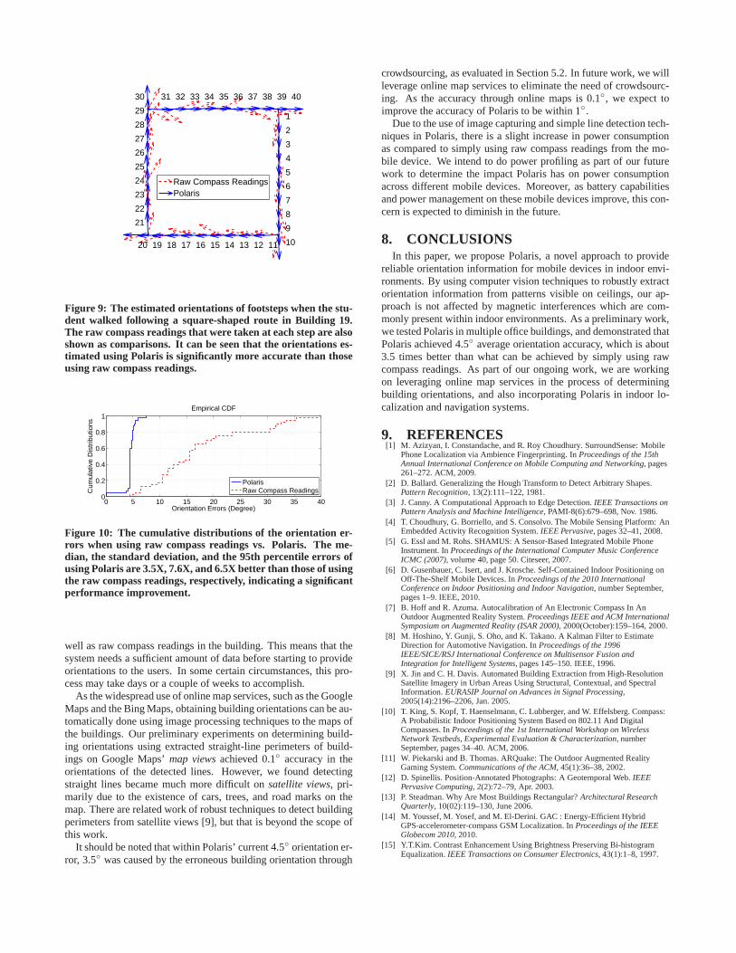
To evaluate the performance of orientation determination,a stu-dent took an iPhone and walked inside Building 19, followingasquare-shaped route. Each edge of the route contained ten steps,with about 0.7m intervals, toward the same direction. Aftertak-ing each step, the student took a ceiling picture, and recorded thecompass readings using the iPhone. After the experiment, the ori-entations of the 40 steps on the route were estimated using Po-laris. Figure 9 shows the estimated orientations and the rawcom-pass readings and Figure 10 shows the cumulative distributions ofthe orientation errors. The median error of using the raw compassreadings was 15.5◦, whereas that of using Polaris was only 4.5◦,about a 3.5X improvement. Furthermore, the standard deviationsand the 95th percentile errors were also reduced from 9.24◦ and35.5◦ to 1.21◦, and 5.5◦, respectively, about 7.6X and 6.5X bet-ter. These results indicate that Polaris significantly improves theaccuracy of orientation determination.
We would like to note that, of the 4.5◦ median error, 3.5◦ is astatic offset that is contributed from errors in detection of building
0.2 0.4 0.6 0.8 1
30
210
60
240
90270
120
300
150
330
180
0
Magnetic NorthEstimated DirectionsGround Truths
Figure 8: The directional axes estimated using the collectedbuilding orientations through crowdsourcing (shown in dottedlight blue lines) of Building 19. They are compared with theground truths. The angular error of the estimated directionalaxes is about 3.5◦.
orientation. If the accuracy of determining building orientationscan be increased, the accuracy of Polaris is expected to improve, aswe will discuss in Section 7.
6. RELATED WORKDigital compasses are predominantly used in ubiquitous comput-
ing research for determining device orientation. Their applicationsrange from localization [1, 10, 14], activity recognition [4], andcomputer-human interaction [5].
Along with the widespread use, however, digital compasses havebeen widely known to provide erroneous readings in indoor en-vironments due to the existence of metallic objects and magneticfields [1, 7, 14]. There are multiple techniques that have beenproposed to compensate for compass errors. The first approach isthrough the use of additional sensors, especially the techniques thatcombine compasses with gyroscopes through the Kalman filtering[10]. However, since the gyroscope does not measure the absoluteorientation, it rely on the initial value of digital compasses, whichmay suffer from systematic offsets. Although some authors comeup with the idea to combine even more sensors, such as the GPSor vision-based recognition software, to calibrate with known land-marks, the overhead and redundancy is still concerning [10].
The second approach is through averaging of sensor readings.For example, in GAC [14], the authors average multiple compassreadings to estimate device orientation over time. However, if thelocation of the compass does not change over time, such as a userholding her mobile phone while sitting in her cubicle, the magneticinterference from the metallic cubicle cannot be eliminated by onlyusing averaging. Moreover, when magnetic anomaly is detected,such as in the iPhone, existing methods often require frequent re-calibration if the user is mobile.
By contrast, Polaris avoids these problems associated within-door environments by using existing and invariant patternson thecelling. Since ceiling patterns are universal and unrelated to mag-netic fields, Polaris can provide accurate orientations formobiledevices even under severe magnetic interferences.
7. DISCUSSIONS AND FUTURE WORKPolaris leverages crowdsourcing to aggregate ceiling pictures as
1
2
3
4
5
6
7
8
9
1011121314151617181920
21
22
23
24
25
26
27
28
29
30 31 32 33 34 35 36 37 38 39 40
Raw Compass ReadingsPolaris
Figure 9: The estimated orientations of footsteps when the stu-dent walked following a square-shaped route in Building 19.The raw compass readings that were taken at each step are alsoshown as comparisons. It can be seen that the orientations es-timated using Polaris is significantly more accurate than thoseusing raw compass readings.
0 5 10 15 20 25 30 35 400
0.2
0.4
0.6
0.8
1
Orientation Errors (Degree)
Cum
ulat
ive
Dis
trib
utio
ns
Empirical CDF
PolarisRaw Compass Readings
Figure 10: The cumulative distributions of the orientation er-rors when using raw compass readings vs. Polaris. The me-dian, the standard deviation, and the 95th percentile errors ofusing Polaris are 3.5X, 7.6X, and 6.5X better than those of usingthe raw compass readings, respectively, indicating a significantperformance improvement.
well as raw compass readings in the building. This means thatthesystem needs a sufficient amount of data before starting to provideorientations to the users. In some certain circumstances, this pro-cess may take days or a couple of weeks to accomplish.
As the widespread use of online map services, such as the GoogleMaps and the Bing Maps, obtaining building orientations canbe au-tomatically done using image processing techniques to the maps ofthe buildings. Our preliminary experiments on determiningbuild-ing orientations using extracted straight-line perimeters of build-ings on Google Maps’map views achieved 0.1◦ accuracy in theorientations of the detected lines. However, we found detectingstraight lines became much more difficult onsatellite views, pri-marily due to the existence of cars, trees, and road marks on themap. There are related work of robust techniques to detect buildingperimeters from satellite views [9], but that is beyond the scope ofthis work.
It should be noted that within Polaris’ current 4.5◦ orientation er-ror, 3.5◦ was caused by the erroneous building orientation through
crowdsourcing, as evaluated in Section 5.2. In future work,we willleverage online map services to eliminate the need of crowdsourc-ing. As the accuracy through online maps is 0.1◦, we expect toimprove the accuracy of Polaris to be within 1◦.
Due to the use of image capturing and simple line detection tech-niques in Polaris, there is a slight increase in power consumptionas compared to simply using raw compass readings from the mo-bile device. We intend to do power profiling as part of our futurework to determine the impact Polaris has on power consumptionacross different mobile devices. Moreover, as battery capabilitiesand power management on these mobile devices improve, this con-cern is expected to diminish in the future.
8. CONCLUSIONSIn this paper, we propose Polaris, a novel approach to provide
reliable orientation information for mobile devices in indoor envi-ronments. By using computer vision techniques to robustly extractorientation information from patterns visible on ceilings, our ap-proach is not affected by magnetic interferences which are com-monly present within indoor environments. As a preliminarywork,we tested Polaris in multiple office buildings, and demonstrated thatPolaris achieved 4.5◦ average orientation accuracy, which is about3.5 times better than what can be achieved by simply using rawcompass readings. As part of our ongoing work, we are workingon leveraging online map services in the process of determiningbuilding orientations, and also incorporating Polaris in indoor lo-calization and navigation systems.
9. REFERENCES[1] M. Azizyan, I. Constandache, and R. Roy Choudhury. SurroundSense: Mobile
Phone Localization via Ambience Fingerprinting. InProceedings of the 15thAnnual International Conference on Mobile Computing and Networking, pages261–272. ACM, 2009.
[2] D. Ballard. Generalizing the Hough Transform to Detect Arbitrary Shapes.Pattern Recognition, 13(2):111–122, 1981.
[3] J. Canny. A Computational Approach to Edge Detection.IEEE Transactions onPattern Analysis and Machine Intelligence, PAMI-8(6):679–698, Nov. 1986.
[4] T. Choudhury, G. Borriello, and S. Consolvo. The Mobile Sensing Platform: AnEmbedded Activity Recognition System.IEEE Pervasive, pages 32–41, 2008.
[5] G. Essl and M. Rohs. SHAMUS: A Sensor-Based Integrated Mobile PhoneInstrument. InProceedings of the International Computer Music ConferenceICMC (2007), volume 40, page 50. Citeseer, 2007.
[6] D. Gusenbauer, C. Isert, and J. Krosche. Self-ContainedIndoor Positioning onOff-The-Shelf Mobile Devices. InProceedings of the 2010 InternationalConference on Indoor Positioning and Indoor Navigation, number September,pages 1–9. IEEE, 2010.
[7] B. Hoff and R. Azuma. Autocalibration of An Electronic Compass In AnOutdoor Augmented Reality System.Proceedings IEEE and ACM InternationalSymposium on Augmented Reality (ISAR 2000), 2000(October):159–164, 2000.
[8] M. Hoshino, Y. Gunji, S. Oho, and K. Takano. A Kalman Filter to EstimateDirection for Automotive Navigation. InProceedings of the 1996IEEE/SICE/RSJ International Conference on Multisensor Fusion andIntegration for Intelligent Systems, pages 145–150. IEEE, 1996.
[9] X. Jin and C. H. Davis. Automated Building Extraction from High-ResolutionSatellite Imagery in Urban Areas Using Structural, Contextual, and SpectralInformation.EURASIP Journal on Advances in Signal Processing,2005(14):2196–2206, Jan. 2005.
[10] T. King, S. Kopf, T. Haenselmann, C. Lubberger, and W. Effelsberg. Compass:A Probabilistic Indoor Positioning System Based on 802.11 And DigitalCompasses. InProceedings of the 1st International Workshop on WirelessNetwork Testbeds, Experimental Evaluation & Characterization, numberSeptember, pages 34–40. ACM, 2006.
[11] W. Piekarski and B. Thomas. ARQuake: The Outdoor Augmented RealityGaming System.Communications of the ACM, 45(1):36–38, 2002.
[12] D. Spinellis. Position-Annotated Photographs: A Geotemporal Web.IEEEPervasive Computing, 2(2):72–79, Apr. 2003.
[13] P. Steadman. Why Are Most Buildings Rectangular?Architectural ResearchQuarterly, 10(02):119–130, June 2006.
[14] M. Youssef, M. Yosef, and M. El-Derini. GAC : Energy-Efficient HybridGPS-accelerometer-compass GSM Localization. InProceedings of the IEEEGlobecom 2010, 2010.
[15] Y.T.Kim. Contrast Enhancement Using Brightness Preserving Bi-histogramEqualization.IEEE Transactions on Consumer Electronics, 43(1):1–8, 1997.