Pocket Guide to Automatic Sprinklers/media/shamrock/P8807.pdf · 2016-08-31 · Pocket Guide to...
26
Sixth Edition Pocket Guide to Automatic Sprinklers
Transcript of Pocket Guide to Automatic Sprinklers/media/shamrock/P8807.pdf · 2016-08-31 · Pocket Guide to...

Sixth Edition
Pocket Guide to Automatic Sprinklers

Pocket Guide to Automatic Sprinklers*A guide to automatic sprinkler systems to assist the fire service in training for and fighting fire in sprinklered facilities
Sixth Edition
* This guide is not intended to be used to design sprinkler systems.

Table of ContentsIntroduction . . . . . . . . . . . . . . . . . . . . . . . . . . . . . . . . . . . . . . . . . . . 5Sprinklers
Operation . . . . . . . . . . . . . . . . . . . . . . . . . . . . . . . . . . . . . . . . . . . 6Types of systems . . . . . . . . . . . . . . . . . . . . . . . . . . . . . . . . . . . . . 6Alarms . . . . . . . . . . . . . . . . . . . . . . . . . . . . . . . . . . . . . . . . . . . . . 9Types of sprinklers . . . . . . . . . . . . . . . . . . . . . . . . . . . . . . . . . . . 9Other types . . . . . . . . . . . . . . . . . . . . . . . . . . . . . . . . . . . . . . . . 14Discharge coefficients . . . . . . . . . . . . . . . . . . . . . . . . . . . . . . . . 17Temperature ratings . . . . . . . . . . . . . . . . . . . . . . . . . . . . . . . . . 18Sprinkler sensitivity . . . . . . . . . . . . . . . . . . . . . . . . . . . . . . . . . 20Control valves . . . . . . . . . . . . . . . . . . . . . . . . . . . . . . . . . . . . . . 22
Where Sprinklers Are Needed . . . . . . . . . . . . . . . . . . . . . . . . . . . 25Commodity Classification . . . . . . . . . . . . . . . . . . . . . . . . . . . . . . 27Common Causes of Sprinkler System Failure . . . . . . . . . . . . . . . 29Sprinkler Piping and Spacing . . . . . . . . . . . . . . . . . . . . . . . . . . . . 31
Water supplies for automatic sprinklers (Fig . 1) . . . . . . . . 32–33
This pocket guide is made available for informational purposes only in support of the insurance relationship between FM Global and its clients. This information does not change or supplement policy terms or conditions. The liability of FM Global is limited to that contained in its insurance policies.

Table of Contents (continued)
Water Supply . . . . . . . . . . . . . . . . . . . . . . . . . . . . . . . . . . . . . . . . 34Valves . . . . . . . . . . . . . . . . . . . . . . . . . . . . . . . . . . . . . . . . . . . . 35Inspector’s test connection . . . . . . . . . . . . . . . . . . . . . . . . . . . . 37Fire service pumper connection (Fig . 2) . . . . . . . . . . . . . . . . . 38
Fighting Fire in Sprinklered Buildings . . . . . . . . . . . . . . . . . . . . 39Before the fire . . . . . . . . . . . . . . . . . . . . . . . . . . . . . . . . . . . . . . 39On the fireground . . . . . . . . . . . . . . . . . . . . . . . . . . . . . . . . . . . 43Nozzle discharge table . . . . . . . . . . . . . . . . . . . . . . . . . . . . . . . 45
Introduction
Automatic sprinklers are, in effect, mechanical firefighters designed for fire control and suppression . FM Global, an insurance organization with a unique risk management focus, has prepared this pocket guide to help you under-stand how an automatic sprinkler system works and how you can work with it .
5

Sprinklers
Operation
An automatic sprinkler system is a network of pipes located at roof/ceiling level that is connected to a source of water, with regularly spaced nozzles (sprinklers), designed to deliver water onto a fire . In the most common configuration, the nozzles are held closed by a mechanism (typically a solder link or glass bulb) that is designed to release when heated to a predetermined temperature, allowing water to discharge, hit the sprinkler’s deflector and form an umbrella-like spray pattern over the fire . Each sprinkler operates independently .
Types of systems
The wet-pipe system is the most common . The sprinkler piping is filled with water under pressure . When a sprinkler operates, the water immediately discharges and continues to flow until the system is shut off . This is the simplest and most reliable type .
The dry-pipe system is used in unheated areas to prevent water from freezing in piping . The piping contains pressur-ized air or nitrogen that keeps a clapper within the dry-pipe valve closed, thus preventing water from initially entering the system . The dry-pipe valve itself is maintained in a heated area to prevent the water located below the clapper from freezing . When a sprinkler operates, pressurized air escapes through the open sprinkler, thus lowering the air pressure within the system . Eventually, the air pressure drops low enough to allow the water pressure to push the clapper open, allowing water to enter the sprinkler system . This type of system, however, has an inherent delay of water discharge onto the fire due to the time it takes the clapper valve to trip, coupled with the time it takes the water to fill up the sprinkler system . It is less reliable because of the complexity of the mechanism involved in the dry-pipe valve, and requires more maintenance .
The preaction system is similar to a dry-pipe system, but typically is used in areas highly susceptible to damage from accidental sprinkler discharge resulting from mechanical damage to sprinklers or piping . It also can be used in place
76

of a dry-pipe system . Water is prevented from entering system piping by a closed valve (called a preaction valve) that is controlled by a detection system acceptable for the occupancy being protected . If a sprinkler or pipe is damaged, water does not enter the system . In the event of a fire, however, in addition to the sprinkler operating, the detection system also operates, allowing water to enter the system . While this type of system partially reduces the delay in delivering water to sprinklers that exists with a dry-pipe system, it is even less reliable because it requires operation of both the preaction valve and the detection system . Also, additional maintenance is needed to service both the preaction valve and its detection system .
The deluge system is similar in arrangement to the preaction system, except the sprinklers are open (i .e ., they have no fusible element), or specially designed nozzles are used . Water discharges from all sprinklers simultaneously, wetting down the entire protected area . This system is used in high-hazard occupancies where immediate discharge of large quantities of water is needed .
Alarms
All sprinkler systems include a mechanism for sounding an alarm when water discharges .
A local alarm sounds in the area of the sprinklers that operate, alerting personnel and assisting firefighters in locating the fire .
A proprietary or central station alarm sends an alarm signal to a constantly attended supervisory station where an operator receives the alarm and notifies the fire service . This alarm also can send a signal directly to the fire service .
Types of sprinklers
FM Global divides industrial/commercial sprinklers into three basic categories, based on their intended use . These three categories are Storage sprinklers, Non-Storage sprin-klers and Special Protection sprinklers . Storage sprinklers are intended to be installed in the presence of storage and other, similar high-hazard occupancy hazards . Non-Storage sprinklers are intended to be installed in the presence of
98

manufacturing and similar moderate- and low-hazard occu-pancy hazards . Special Protection sprinklers are intended to be installed in the presence of special hazard, non-room environments, such as the inside of cooling towers and combustible ducts, or outdoor hazards such as transformers, ignitable liquid storage tanks, and building exteriors . The performance of the sprinkler could be either suppression or control . Based on the attributes of the sprinkler and the water supply provided and depending on the occupancy hazard the sprinkler is protecting .
Prior to 2010, FM Global divided industrial/commercial sprinklers into three basic categories . In order of develop-ment, they were: control-mode density area (CMDA), control-mode specific application (CMSA) and suppres-sion-mode . Within these categories, sprinklers were made in three orientations: upright, pendent and sidewall .
Control-mode density area sprinklers have changed notably over the years both in shape and in size, but they still essentially function the same way as the first sprinklers that were invented in the late nineteenth century . They
control a fire through a combination of pre-wetting com-bustible material on the periphery of the fire and cooling hot gas from a fire at the roof or ceiling . Very little, if any, of the water from sprinklers actually penetrates the flames . If the sprinkler design is adequate for the occupancy being protected, the pre-wetting limits the fire spread while the cooling effect maintains structural stability until the fire is extinguished by firefighters . This type of protection, while less expensive than other types, is limited in the hazards it can protect against and results in larger areas of fire, smoke and water damage than newer sprinkler technology . Designs for this sprinkler are specified in terms of a discharge density (gpm/ft .2 or mm/min .) over a sprinkler operating area .
Control-mode specific application sprinklers are a newer technology that also control fire in the same manner as control-mode density area sprinklers . These sprinklers were originally developed to provide control for high-hazard type occupancies, such as storage . Sprinkler system designs for this sprinkler type are specified in terms of the number of sprinklers expected to operate during a fire at a given minimum required pressure .
1110

Suppression-mode sprinklers represent the newest tech-nology, and were specifically developed to protect storage without the need for in-rack sprinklers . Through a com-bination of increased sensitivity and a highly engineered, high-momentum water discharge, they respond while a fire is small, and suppress its growth, reducing fire and non-thermal damage . While offering obvious advantages, this type of sprinkler requires careful design and installation; otherwise, the sprinkler performance could be crippled . Sprinkler system designs for this sprinkler type are also classified by the number of sprinklers expected to operate during a fire at a given minimum required pressure .
Upright sprinklers are designed for installation on the top of sprinkler piping, with the deflector positioned above the orifice . This is the most common orientation for control-mode sprinklers .
Pendent sprinklers are installed on the underside of piping, with the deflector located below the orifice . This orientation is most common for suppression-mode sprinklers . This
type of sprinkler is not commonly used in either dry- or preaction-type sprinkler systems because of the inability to completely drain the water that would accumulate directly above the sprinkler . This would expose the sprinkler to potential freeze damage or the internal piping of the sprinkler system to iron oxidation . In addition, this type of sprinkler is not commonly used when the water source for fire protection is from an open body of water, wherein sediment and other foreign material can enter the sprinkler system and potentially settle on top of the sprinkler .
Sidewall sprinklers have a specially designed deflector that discharges water horizontally in one direction only .
The sprinkler on the left is a pendent, and the one on the right is an upright. Note the flat deflector on the pendent as compared with the curved, umbrella-like deflector on the upright. Both sprinklers are fusible-link type.
1312

They are installed along walls in rooms of limited size to eliminate the need for sprinklers in the center of the room . These sprinklers are suited only for relatively low-hazard occupancies, and not for manufacturing or storage occupancies .
Other types
Extended-coverage (EC) sprinklers are made to provide protection equivalent to other sprinklers, but are specifi-cally designed to be installed on linear and area spacings that exceed the normal sprinkler spacing requirements . A potential advantage of EC sprinklers is the reduced cost of installation, both in terms of the number of sprinklers and piping needed for installation and the reduced labor needed to install them . They are available in a variety of models, each designed to protect a specific occupancy . Extreme care must be taken in the selection and design of these sprinklers to ensure they are FM Approved for the application in which they are to be used .
Corrosion-resistant sprinklers are made of corrosion- resistant material like stainless steel . They also may be supplied with a factory-applied corrosion-resistant coating . These sprinklers can provide improved corrosion protection, but should be selected for compatibility with the specific corrosive environment . They require regular inspection and may require more frequent replacement .
Flush, recessed and concealed sprinklers are all pendent or sidewall sprinklers . Installed in ceilings and/or walls, they are designed to be less visually obtrusive, but, as a result, tend to be more costly than sprinklers having similar attributes . The fusible element of the flush sprinkler is installed flush with the ceiling . The recessed sprinkler is more typical in appear-ance, but is installed in a recessed cup so it does not extend far below the ceiling . The concealed sprinkler’s operating mechanism is located entirely above the ceiling, with a cover plate installed flush with the ceiling . This cover plate is held in place by solder that melts when exposed to heat, releasing the cover plate .
1514

The dry-pendent and dry-upright sprinklers are used to provide sprinkler protection in areas subject to freezing, elim-inating the need for a dry-pipe system . They are connected to wet sprinkler piping in a heated area, and extend through a ceiling or wall into the unheated space . A mechanism prevents water from entering the sprinkler until the fusible element operates . These sprinklers are occasionally used on dry-pipe systems to eliminate the need to remove pendent sprinklers to drain the system .
The rack storage sprinkler is a typical ceiling-level sprinkler supplied with a water shield, and is used within rack storage arrays as a supplement to ceiling sprinklers . The water shield prevents spray from other sprinklers from cooling the rack stor-age sprinkler’s fusible element, which could delay its operation . It does not enhance the sprinkler’s sensitivity to heat .
The cooling tower sprinkler is a Special Protection sprin-kler that has a specific purpose: to protect combustible fill areas of water-cooling towers .
Open sprinklers are Special Protection sprinklers that are used mainly in deluge sprinkler systems where all sprinklers are expected to discharge simultaneously .
Window and cornice sprinklers are open Special Protection sprinklers designed to protect windows and combustible cornices against fire caused by outside exposure .
Discharge coefficients
A sprinkler’s orifice is the opening through which the water flows . Its size determines the amount of water that discharges from a sprinkler at a given pressure . Because sprinkler orifices are typically tapered, the orifice size is characterized by its discharge coefficient (k), which is used in the following formula to determine the discharge from a sprinkler: Q = k*P½, where Q is the discharge flow (gpm or L/min .), k is the discharge coefficient of the sprinkler (gal ./min . psi½ or L/min . bar½) and P is the pressure at the operating sprinkler .
1716

Sprinklers of various types are available with nominal discharge coefficients of 2 .8 (40), 5 .6 (80), 8 .0 (115), 11 .2 (160), 14 .0 (200), 16 .8 (240), 22 .4 (325) and 25 .2 (365) .
Temperature ratings
A sprinkler’s thermal-sensing element, whether glass bulb or metal link, operates at a predetermined temperature . For example, a sprinkler rated at 160° F (71° C) will fuse when the bulb or link is heated to that temperature . The rating is usually marked on the sprinkler’s operating element . Sprinkler frames and the liquid in glass bulbs are color-coded according to temperature so their rating is recognizable from a distance (see table below) .
Temperature Ratings Rating
Maximum Temperature at Sprinkler Level
Rated Temperature of
Sprinkler
Frame Color
Glass Bulb Color
Ordinary 100° F (38° C)
135-170° F (57-77° C)
Unpainted1 Orange or red
Intermediate 150° F (66° C)
175-225° F (79-107° C)
White Yellow or green
High 225° F (107° C)
250-300° F (121-149° C)
Blue Blue
Extra high 300° F (149° C)
325-375° F (163-191° C)
Red Purple
Very extra high2
365° F (185° C)
400-475° F (204-246° C)
Green Black
Ultra high2 465° F (241° C)
500-650° F (260-343° C)
Orange Black
1 Frame arms of sprinklers less than 160° F (71° C) may be wholly or partially painted black .
2 These ratings are rarely seen .
The temperature rating required for a sprinkler is determined by the occupancy it protects, as specified in the standard used to design the sprinkler system . Ambient temperature also may dictate the temperature rating of the sprinkler .
1918

Sprinkler sensitivity
The speed at which a sprinkler operates in a fire is not determined by temperature rating as much as might be assumed . At the time sprinklers operate, the temperature of the gas in their vicinity rapidly increases . The temperature of the fusible element lags behind the temperature of the surrounding gas due to the heat required to raise its tem-perature . A larger fusible element and/or higher rate of heat conduction between the element and the sprinkler frame produces a greater delay in operation .
Sprinklers are placed into one of two sensitivity categories: standard-response and quick-response . Prior to the mid-1970s, sprinklers were manufactured with standard-response fusible elements . Since that time more and more sprinklers have been manufactured using a quick-response fusible ele-ment, including residential and extended-coverage sprinklers . Research is presently ongoing to determine the optimum cir-cumstances for each type of thermal element .
Extended-coverage sprinklers use a quick-response thermal element to help achieve an equivalent—or better—time response at their extended sprinkler spacing when com-pared with non-extended-coverage sprinklers on their maxi-mum recommended sprinkler spacing .
It should be noted that there is a difference between a quick-response sprinkler and a sprinkler equipped with a quick-response thermal element . In order to be a quick-response sprinkler, the sprinkler must be equipped with a quick-response thermal element; however, not all sprinklers equipped with quick-response thermal elements are quick-response sprinklers . An example is a concealed sprinkler, the inherent design of which delays the actuation of the thermal element . Concealed sprinklers often are equipped with quick-response thermal elements to help ensure their overall reaction time is within that required of standard-response sprinklers .
21
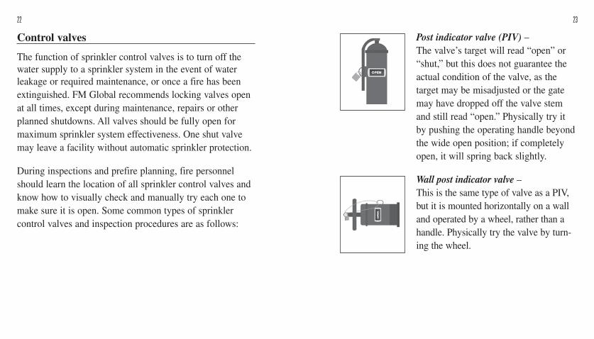
Post indicator valve (PIV) – The valve’s target will read “open” or “shut,” but this does not guarantee the actual condition of the valve, as the target may be misadjusted or the gate may have dropped off the valve stem and still read “open .” Physically try it by pushing the operating handle beyond the wide open position; if completely open, it will spring back slightly .
Wall post indicator valve – This is the same type of valve as a PIV, but it is mounted horizontally on a wall and operated by a wheel, rather than a handle . Physically try the valve by turn-ing the wheel .
Control valves
The function of sprinkler control valves is to turn off the water supply to a sprinkler system in the event of water leakage or required maintenance, or once a fire has been extinguished . FM Global recommends locking valves open at all times, except during maintenance, repairs or other planned shutdowns . All valves should be fully open for maximum sprinkler system effectiveness . One shut valve may leave a facility without automatic sprinkler protection .
During inspections and prefire planning, fire personnel should learn the location of all sprinkler control valves and know how to visually check and manually try each one to make sure it is open . Some common types of sprinkler control valves and inspection procedures are as follows:
2322

Post indicator valve assembly (PIVA ) – Visually inspect to see that the valve’s “see-through” indicator is open . The PIVA’s target, unlike the PIV, will give a true reading of whether the valve is open: the orientation between the valve and indicator is unalterable .
Indicating butterfly valve (IBV) – A visual inspection is adequate; if the target indicates “open,” the valve is open as well .
Outside screw and yoke valve (OS&Y) – A fully extended stem indicates the valve is fully open, and a completely retracted stem indicates it is fully shut . A visual inspection is not totally fail-safe; if in doubt, check by hand .
Where Sprinklers Are Needed
n In all buildings of combustible construction or those having appreciable amounts of combustible components
n In noncombustible buildings with combustible contentsn At hazardous processes like those involving ignitable
liquid, even if protected with fixed extinguishing systemsn In concealed spaces of combustible construction, such
as floors, roofs and low attics, except in certain cases where the ceiling is attached directly to the underside of the supporting beams of a combustible roof or floor
n Under roofs over outside platforms where construction or occupancy is combustible
n In enclosed equipment like ovens, dryers, dust collec-
2524
Curb box/roadway valve – Often, an arrow on the cover plate indicates direction to open . The only way to determine the valve position is to physically try it using a T-wrench .

tors, large ducts, spray booths and similar enclosures where combustible material is processed or where combustible waste or deposits accumulate
n In small enclosed structures like penthouses, stairways, passageways, stockrooms and closets that are combus-tible or contain combustible material
n In elevator towers, including penthouses, and in elevator machine rooms
n Under cutting tables, ducts, platforms and hoods that seriously obstruct sprinklers above
n At exposed steelwork that supports process equipment like large tanks, stills, pipelines, or equipment containing ignitable chemicals or liquid, where the steel would not be well-protected by the usual building sprinklers
n When combustible storage or construction is added to areas where buildings and contents are noncombustible
Commodity Classification
An important consideration in sprinkler system design is the burning characteristics of material inside a particular occupancy . This is particularly true for warehouses containing large quantities of combustible material . The stored goods, or commodities, are classified according to their burning characteristics—how fast they burn and how much heat they contain . For instance, plastic contains more than twice the heat of an equal amount of wood . Even if the two were to burn at the same rate as wood, plastic would have more than double the heat-release rate .
Typical stored commodities are divided (in order of increasing fire challenge) into Class 1, 2, 3 and 4, Plastic and Special Hazards .
Class 1: Essentially noncombustible products stored on wood pallets:n glassn metaln minerals
2726
n some types of foods e .g ., fruits and vegetables
n ceramic

Class 2: Noncombustible products in cardboard cartons on wood pallets .
Class 3: The non-plastic combustible products listed below, in cardboard cartons on wood pallets:n woodn papern leather
expanded, as well as cartoned or uncartoned, with cartoned unexpanded plastic being the lesser plastic commodity hazard and uncartoned expanded plastic being the highest plastic commodity hazard .
Special Hazards: These can pose a more severe fire hazard than the above commodities:n aerosolsn rolled non-woven
fabricn ignitable liquid
2928
n textilesn some types of food
Class 4: Class 1, 2 or 3 commodity with up to 25% by volume or 15 percent (by weight) of plastic in the product, uniformly distributed in the product, in cardboard cartons on wood pallets:n metal office equipment with plastic partsn cameras with plastic parts
Plastic: Plastic products are those that incorporate plastic material, such as polystyrene, polypropylene, polyethylene, polyurethane and acrylonitrile-butadiene-styrene (ABS), all of which have a heat of combustion that is much higher than that of ordinary combustible material . Paraffin and natural “beeswax” also fall into this category . Plastic com-modities are generally classified as either unexpanded or
n roll papern rubber tires
Common Causes of Sprinkler System Failure
Sprinkler system failure can generally be traced to one of three major causes:1 . A design deficiency in the sprinkler system can result
when the quantity or volume of water available is not adequate to control a fire . The water supply itself may be inadequate, or the sprinkler system may be improp-erly designed for the facility and commodities stored inside . Each automatic sprinkler system is designed for a specific occupancy . The original system design may

30 31
this only prevents sprinklers from gaining control of a fire in its critical development stage . Even if the valve is turned on again, the fire already may have grown beyond the point where sprinklers can control it .
Sprinkler Piping and Spacing
Most systems installed since 1980 are hydraulically designed . Sprinkler contractors use computer programs to custom-design the exact protection configuration needed to meet a specific facility’s needs .
Some warning signs to watch for with hydraulically designed systems: n Be sure not to limit future flexibility to save a relatively
small amount of money on the installation cost . The occupancy may change, which could easily render protection inadequate . Anticipate future changes wherever possible .
n The water supply may deteriorate over time because of mineral or scale buildup, leaving the original system with inadequate pressure and flow . Allow some margin in the sprinkler design to accommodate such changes .
have been adequate, but a change to a more hazardous commodity—for instance, from metal parts storage to plastic—can render a protection system inadequate . Even seemingly minor changes within a warehouse can compromise existing sprinkler protection .
2 . An impairment to the sprinkler system before a fire generally occurs when a sprinkler system is shut off during new construction or building renovations, or when an obstruction like a rock works its way into sprinkler piping and blocks the flow of water . Another scenario is becoming increasingly common: an incen-diary (intentional firesetter) will purposely close sprin-kler control valves and set fire to the building, knowing the sprinklers won’t work . FM Global statistics show incendiarism as one of the leading causes of storage fire .
3 . An impairment to the system during a fire is perhaps the most serious threat to a fully sprinklered building . Shutting off sprinkler control valves prematurely during a fire turns off the water to sprinklers . Facility employees or members of the fire service may shut the valve to reduce smoke or control water damage; but,

3332
Fig. 1. Water supplies for automatic sprinklers

Valves
Valves are located throughout this system of pipes . They serve two functions: (1) retain the system’s water supply for immediate fire protection use; and (2) minimize the areas that would be put out of service during repair to the sprinkler system .
The supply control valve controls the flow of water from the public water supply to the yard system .
The check valve holds water in the yard system if it is maintained at a higher pressure; it prevents water from flowing back into the public system . The check valve is located between two supply control valves . When they are closed, the check valve can be isolated for maintenance .
The backflow preventer is a valve assembly that prevents undesirable reverse flow of water into a potable water supply .
The pressure-reducing valve (PRV) reduces high-inlet water pressure to a lower outlet pressure in both static and flowing conditions .
Water Supply
A sprinkler system’s water supply must supply not only sprinklers, but also fire hose streams . This water is supplied to a facility via several sources (see Fig . 1 on pages 32–33) .
The most common source is the public water system . Its available pressure and volume must be adequate for the facility being protected . In some cases, a booster pump may be connected to the public supply to boost the system’s pressure to the necessary level .
A static suction source requires a fire pump to provide the necessary water volume and pressure to the system . Tanks, wells, reservoirs or rivers are suction sources . Gravity tanks also are used, but are less common today .
Water reaches a sprinkler system via a loop or a series of large underground pipes called yard mains . A lead-in pipe delivers water from the yard mains to a riser, a vertical pipe that brings water from below ground to ceiling level . Feed mains and cross mains further distribute the water through-out the building . A network of smaller pipes, called branch lines, feeds the water to sprinklers .
3534

Inspector’s test connection
The sprinkler system is equipped with an inspector’s test connection to provide a method for testing sprinkler system alarms . The connection is on the branch line, usually at the most remote point from the sprinkler riser (see Fig .1 on pages 32–33) . Flowing water through the test connection ensures water is flowing through the system and that the alarm systems are working .
Three other types of connections are featured on a facility’s fire protection system: the fire service pumper connection, the fire hydrant and the 2-in . (51-mm) drain .
The fire service pumper connection (also known as a siamese connection) enables the fire service to pump water from a public hydrant or suction source into the yard system . The pumper increases the pressure and, in some cases, the volume of water delivered to the yard system . Increasing the water pressure enables automatic sprinklers to deliver more water over a fire . An increase in water volume can allow the fire service to use additional hose
Divisional valves are located on the yard system . Closing two divisional valves can isolate a section of the yard main (for maintenance or repair) without shutting down protection of the entire facility .
Similarly, closing a sprinkler control valve to shut down only one section of the sprinkler system can minimize the size of an area left unprotected during maintenance or repair .
Sprinkler systems that require fire pumps have two kinds of valves: a suction valve that isolates the fire pump from its static water supply, e .g ., river, tank or reservoir, and a discharge valve that controls the flow of water from the pump to the fire protection system . Closing the discharge valve isolates the pump from the yard system when pump maintenance is necessary . With the exception of mainte-nance or the annual pump test, the suction and discharge valves should be open at all times .
3736

Hydrants provide a connection to the water supply . Firefighters use them to fight exterior fire or direct hose streams into shielded areas .
The 2-in. (51-mm) drain on the riser is used to drain a system when repair is necessary . The drain also can provide temporary protection . A coupling is used to attach one end of a hose to the drain and the other end to a hydrant . This temporary hookup enables the fire service to supply water to sprinkler systems that are out of service due to impairment .
Fighting Fire in Sprinklered Buildings
Before the fire
To prepare for a fire at a sprinklered facility, firefighters should regularly visit the property to become thoroughly familiar with its layout, contents, construction and fire protection features . (These are not inspections for code violations .) The information from these visits can then be used in prefire planning sessions between fire service and
lines from yard hydrants . The proper connection between the fire service engine and the fire service connection is illustrated in Fig . 2 .
3938
Fig. 2. The fire service engine at top is connected to the street hydrant, with hose lines laid at the back of the building for manual firefighting. The engine below is hooked up to the street hydrant and to the fire service pumper connection to boost water volume and pressure to automatic sprinklers.

6 . Note the location(s) of fire service pumper (siamese) connections . Identify which connections feed entire buildings, individual sprinkler systems and/or standpipes . The responsibility of boosting the water supply to sprinklers via the pumper connection(s) should be assigned to one of the fire service’s first-arriving pumpers .
7 . Locate all available water supply sources . Check their capacity, reliability and accessibility . If up-to-date flow test data is unavailable, fire service or facility personnel should conduct or observe flow tests of water mains to ensure an ample supply is available for both hose lines and sprinklers . If fire service personnel conduct the water test, they may find the information on the nozzle discharge table (pages 46–47) helpful .
8 . If fire pumps are available, note their starting arrangement; if they are automatic, check their actuating pressure .
9 . Become familiar with the alarm system, and know where its signal is transmitted .
facility personnel . A prefire planning session gives both groups an opportunity to coordinate fire response . A thorough prefire planning session will include the following:1 . If available, review the facility’s site plan . It includes
building construction features, occupancy, sprinkler system feeds, sprinkler control valve locations and special protection arrangements .
2 . Review the layout of the building and decide on the best access routes to each area .
3 . Review building construction features, such as square footage (meters), roof deck, walls, etc .
4 . Know the building’s occupancy and storage contents . Note any changes in building occupancy that occurred since the installation of the sprinkler system . A change in occupancy is one of the major causes of sprinkler system failure .
5 . Review the locations of sprinkler control valves and the areas they protect . Sprinkler control valves should be kept open until the fire is completely out . Prematurely shutting the valves is one major reason why sprinkler systems fail .
4140

Preassign company duties: know which companies will connect to the pumper connection, attack the fire and ventilate the building . Inform mutual-aid fire companies of these assignments to avoid confusion on the fireground .
On the fireground
In fighting a sprinklered fire, one of the most important roles the fire service can perform is to maintain the integrity of the automatic sprinkler system throughout the fire . Upon arrival, the fire service should know what steps to take to ensure sprinklers continue their firefighting momentum . These steps should be outlined in standard operating procedures that are developed from information gathered during prefire planning sessions . Some basic guidelines are as follows:1 . Size up and rescue. Upon arrival, size up the location
and extent of the fire, and initiate search and rescue operations .
2 . Check sprinkler control valves. If safe to do so, send a firefighter to make sure the main sprinkler control valve is open . If possible, station someone at each valve that controls operating sprinklers to make
10 . Establish procedures for facility personnel to notify the fire service when alarms, sprinkler systems or fire pumps are out of service . If alarms aren’t functioning, set up a temporary notification procedure . When sprinklers or pumps are out of service, notify the fire service so personnel can plan their response in the event of a fire .
11 . For facilities with automatic (temperature-activated) smoke vents, make sure the temperature rating of the vent is higher than the temperature rating of the sprinkler heads, so the sprinklers open first .
12 . Coordinate procedures between the fire service and the facility’s emergency response team (ERT) . Changes to current ERT procedures may be needed if the fire service foresees any conflict with its own duties .
13 . Schedule future periodic visits at the facility to con-tinually update the information from steps 1–12 .
Use the information from these sessions to develop standard operating procedures for fighting a fire at the facility .
4342

sure valves remain open and sprinklers continue to operate until the fireground commander orders them shut . Remember, valves should remain open until the fire is completely extinguished . Shutting down the sprinkler system to clear the air of smoke may increase the risk of fire spread .
3 . Boost water supply to sprinklers. One of the first arriving pumpers should hook up to the fire service pumper connection to boost water volume and pressure to the sprinkler system . Recommended pressure is 150 psi (10 .4 bar) .
4 . Lay hose lines. After fire service connections are made, larger hose lines should be laid and ready to use if needed . Make sure hose lines are not competing with sprinklers for water . If water to sprinklers is depleted, fire will spread and fuse other sprinklers, further aggra-vating water supply problems .
5 . Ventilate. Once the fire has been suppressed, the fire service should ventilate a building manually by opening doors, windows and manual/automatic roof hatches .
6 . Salvage. Salvage can be performed by both firefighters and members of a facility’s emergency response team .
7 . Overhaul. After the fire is extinguished and the sprinklers are ordered shut, the fire service can perform a routine overhaul . Always check for fire spread in adjacent areas before shutting the sprinkler control valve .
Nozzle discharge table
This table shows pressures required at the hydrant or fire service pumper, while stream is flowing, to maintain nozzle pressure indicated in the first column through various lengths of best quality woven-jacket rubber-lined hose .
44 45

4746
1¾-in. (44-mm) Smooth Nozzle (Playpipe)
Nozzle
Pressure, psi (bars)
Discharge gpm (L/
min)
Hydrant Pressure, psi (bars)
Single 2½-in . (64-mm) lines, ft . (m)
50 (15) 100 (30 .5) 150 (45 .7) 200 (61)
2 (0 .1) 4 (0 .3) 6 (0 .4) 8 (0 .6) 10 (0 .7)
125 (473) 178 (674) 217 (821) 251 (950)280 (1060)
4 (0 .3) 8 (0 .6) 13 (0 .9) 17 (1 .2) 21 (1 .5)
6 (0 .4) 12 (0 .8) 18 (1 .2) 24 (1 .7) 30 (2 .1)
8 (0 .6) 16 (1 .1) 23 (1 .6) 31 (2 .1) 38 (2 .6)
9 (0 .6) 19 (1 .3) 29 (2 .0) 39 (2 .7) 48 (3 .3)
12 (0 .8) 14 (1 .0) 16 (1 .1) 18 (1 .2)
307 (1162) 332 (1257) 354 (1340) 376 (1423)
25 (1 .7) 29 (2 .0) 34 (2 .3) 38 (2 .6)
36 (2 .5) 42 (2 .9) 48 (3 .3) 54 (3 .7)
46 (3 .2) 54 (3 .7) 62 (4 .3) 69 (4 .8)
58 (4 .0) 68 (4 .7) 77 (5 .3) 87 (6 .0)
20 (1 .4) 22 (1 .5) 24 (1 .7) 26 (1 .8)
397 (1503) 416 (1575) 435 (1647) 452 (1711)
42 (2 .9) 46 (3 .2) 50 (3 .5) 54 (3 .7)
60 (4 .1) 66 (4 .5) 72 (5 .0) 78 (5 .4)
77 (5 .3) 85 (5 .9) 93 (6 .4) 101 (7 .0)
96 (6 .6) 106 (7 .3) 116 (8 .0) 126 (8 .7)
28 (1 .9) 30 (2 .1) 32 (2 .2) 34 (2 .3)
469 (1775) 486 (1840) 502 (1900) 517 (1957)
58 (4 .0) 63 (4 .3) 67 (4 .6) 72 (5 .0)
84 (5 .8) 90 (6 .2) 96 (6 .6) 102 (7 .0)
112 (7 .7) 120 (8 .3) 128 (8 .8) 135 (9 .3)
135 (9 .3)145 (10 .0) 155 (10 .7) 165 (11 .4)
36 (2 .5) 38 (2 .6) 40 (2 .8) 42 (2 .9)
532 (2014) 547 (2071) 561 (2141) 574 (2173)
76 (5 .2) 80 (5 .5) 85 (5 .9) 89 (6 .1)
108 (7 .5) 114 (7 .9) 120 (8 .3) 126 (8 .7)
143 (9 .9)150 (10 .3) 158 (10 .9) 165 (11 .4)
175 (12 .1) — — —
44 (3 .0) 46 (3 .2) 48 (3 .3) 50 (3 .5)
588 (2226) 601 (2275) 614 (2324) 627 (2373)
93 (6 .4) 97 (6 .7) 101 (7 .0) 106 (7 .3)
132 (9 .1) 138 (9 .5) 144 (9 .9)149 (10 .3)
173 (12 .0) 181 (12 .5)
— —
— — — —
Nozzle pressure = pitot tube pressure, discharge coefficient = 0 .97
1¾-in. (44-mm) Smooth Nozzle (continued)
Nozzle
Pressure, psi (bars)
Discharge gpm (L/
min)
Hydrant Pressure, psi (bars)
Single 2½-in . (64-mm) lines, ft . (m)
50 (15) 100 (30 .5) 150 (45 .7) 200 (61)
52 (3 .6) 54 (3 .7) 56 (3 .9) 58 (4 .0) 60 (4 .1)
639 (2419) 651 (2464) 663 (2510) 675 (2555) 687 (2601)
110 (7 .6) 115 (7 .9) 119 (8 .2) 123 (8 .5) 127 (8 .8)
154 (10 .6) 160 (11 .0) 166 (11 .5) 172 (11 .9)
—
— — — —
— — — —
62 (4 .3) 64 (4 .4) 66 (4 .6) 68 (4 .7)
698 (2642) 709 (2684) 720 (2725) 731 (2767)
131 (9 .0) 135 (9 .3) 140 (9 .7)145 (10 .0)
— — — —
— — — —
— — — —
70 (4 .8) 72 (5 .0) 74 (5 .1) 76 (5 .2)
742 (2809) 753 (2850) 763 (2888) 773 (2926)
149 (10 .3) 154 (10 .6) 158 (10 .9) 163 (11 .2)
— — — —
— — — —
— — — —
78 (5 .4) 80 (5 .5) 82 (5 .7) 84 (5 .8)
783 (2964) 793 (3002) 803 (3040) 813 (3078)
167 (11 .5) 172 (11 .9) 177 (12 .3)
—
— — — —
— — — —
— — — —
86 (5 .9) 88 (6 .1) 90 (6 .2) 92 (6 .3)
823 (3115) 832 (3149) 841 (3184) 850 (3218)
— — — —
— — — —
— — — —
— — — —
94 (6 .5) 96 (6 .6) 98 (6 .8) 100 (6 .9)
859 (3252) 868 (3286) 877 (3320) 887 (3358)
— — — —
— — — —
— — — —
— — — —
Nozzle pressure = pitot tube pressure, discharge coefficient = 0 .97

P8807 © FM Global (Rev. 11/2012) All rights reserved. www.fmglobal.com
Contact Us: To report an impairment or to find an FM Global office nearest you, visit www.fmglobal.com/contact.
Report A Loss: Dial (1)877 NEW LOSS (639 5677)* to report a property or cargo loss 24 hours a day, seven days a week. Or, to contact your client service team or designated claims office directly, go to www.fmglobal.com/claims or www.affiliatedfm.com/claims for location and contact information.
* For clients of FM Global and Affiliated FM in Canada and the United States only.
Product Ordering Information:For additional copies of this publication or other FM Global resources, order online 24 hours a day, seven days a week at www.fmglobalcatalog.com.
Or, for personal assistance worldwide, contact our U.S.-based customer services team, Monday – Friday, 8 a.m. – 5 p.m. ET: n Call: (1)877 364 6726 (Canada and
the United States) n Call: +1 (1)401 477 7744 (worldwide) n Fax: (1)401 477 7010 n E-mail: [email protected]
In the United Kingdom: FM Insurance Company Limited 1 Windsor Dials, Windsor, Berkshire, SL4 1RS Regulated by the Financial Services Authority.