Pneumatic Systems - Keith Grammar Technical...
83
ENGINEERING SCIENCE Pneumatic Systems
Transcript of Pneumatic Systems - Keith Grammar Technical...

Engineering Science: Pneumatics ENGINEERING SCIENCE
Technological Studies
Technological Studies
Pneumatic Systems

Engineering Science: Pneumatics
Page 2
Section 1: Pneumatic Systems
Introduction
Pneumatics is something that you probably know very little about yet come across every day without even realising it. Some examples of everyday pneumatic systems are shown below. How many do you recognise?
Figure 1 Pneumatics is also used a lot in industry and you would expect to see pneumatic systems in factories, production lines and processing plants. It can be used to do lots of different jobs such as moving, holding or shaping objects.
MOVE HOLD
FORM PROCESS
Figure 2
Page 3
Engineering Science: Pneumatics
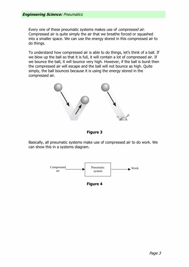
Every one of these pneumatic systems makes use of compressed air. Compressed air is quite simply the air that we breathe forced or squashed into a smaller space. We can use the energy stored in this compressed air to do things. To understand how compressed air is able to do things, let’s think of a ball. If we blow up the ball so that it is full, it will contain a lot of compressed air. If we bounce the ball, it will bounce very high. However, if the ball is burst then the compressed air will escape and the ball will not bounce as high. Quite simply, the ball bounces because it is using the energy stored in the compressed air.
Figure 3
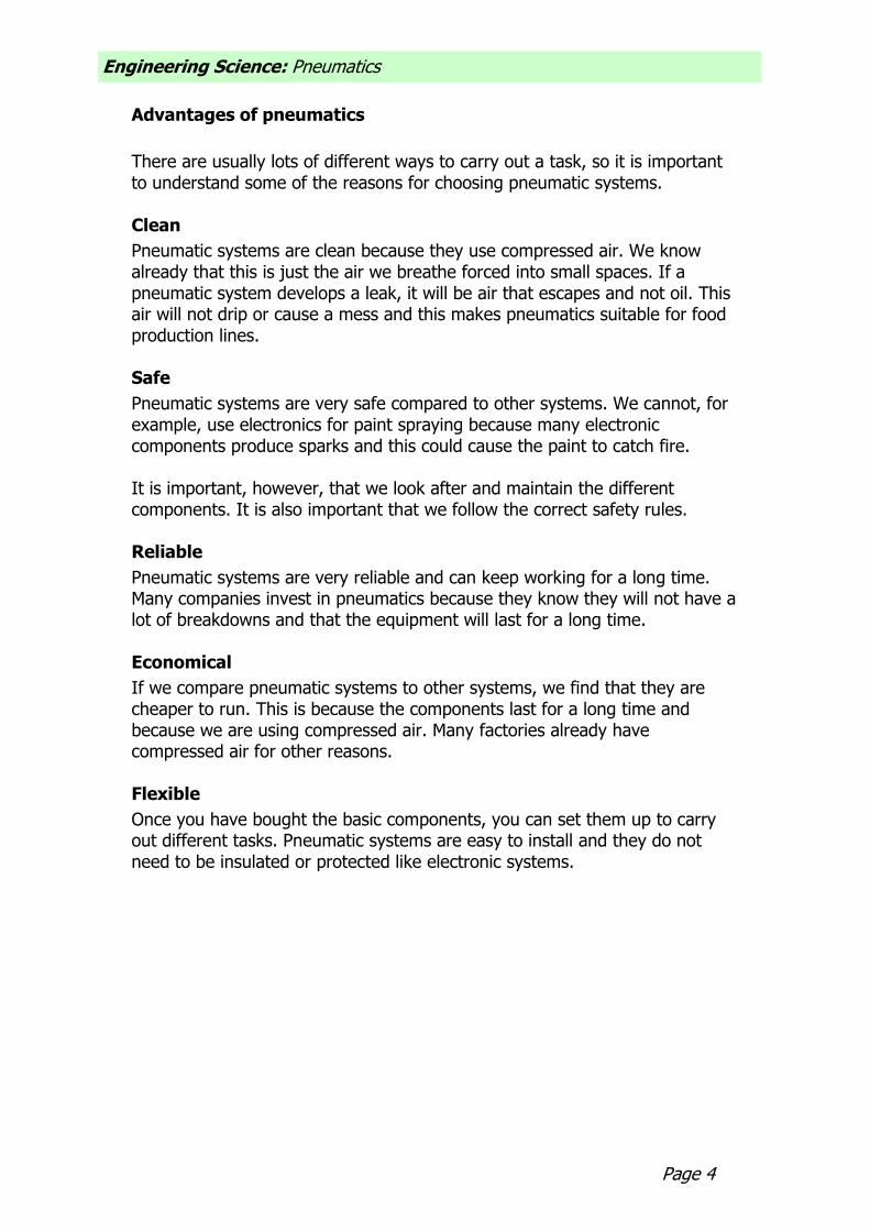
Basically, all pneumatic systems make use of compressed air to do work. We can show this in a systems diagram.
Pneumatic
system
Compressed
airWork
Figure 4
Engineering Science: Pneumatics
Page 4
Advantages of pneumatics
There are usually lots of different ways to carry out a task, so it is important to understand some of the reasons for choosing pneumatic systems. Clean
Pneumatic systems are clean because they use compressed air. We know already that this is just the air we breathe forced into small spaces. If a pneumatic system develops a leak, it will be air that escapes and not oil. This air will not drip or cause a mess and this makes pneumatics suitable for food production lines. Safe
Pneumatic systems are very safe compared to other systems. We cannot, for example, use electronics for paint spraying because many electronic components produce sparks and this could cause the paint to catch fire. It is important, however, that we look after and maintain the different components. It is also important that we follow the correct safety rules. Reliable
Pneumatic systems are very reliable and can keep working for a long time. Many companies invest in pneumatics because they know they will not have a lot of breakdowns and that the equipment will last for a long time. Economical
If we compare pneumatic systems to other systems, we find that they are cheaper to run. This is because the components last for a long time and because we are using compressed air. Many factories already have compressed air for other reasons. Flexible
Once you have bought the basic components, you can set them up to carry out different tasks. Pneumatic systems are easy to install and they do not need to be insulated or protected like electronic systems.

Page 5
Engineering Science: Pneumatics
Assignment 1
1. Give three examples of the everyday use of pneumatics. 2. Choose one of your examples from question 1. Draw a system diagram
and describe how it makes use of compressed air. 3. What is compressed air? 4. Think about blowing up a balloon. What happens to the balloon if you let
it go? Why does this happen? 5. Give two reasons why pneumatic systems are used in industry.

Engineering Science: Pneumatics
Page 6
Supplying compressed air
We know already that pneumatic systems need compressed air to make them work. A bicycle pump can produce compressed air. This is all right for inflating the tyres on your bicycle, but can you imagine trying to blow up all the tyres on a lorry using this? You would soon become tired, exhausted even. In order to supply pneumatic systems with compressed air we use a machine called a compressor. Compressors come in lots of different shapes and sizes but they all work in the same way.
Figure 5 A pump that is driven by a motor, sucks in air from the room and stores it in a tank called the receiver. You will be able to hear the compressor when it is running. Sometimes though, it will stop because the receiver is full. Ask your teacher to see the compressor that will be supplying your compressed air.
Not everyone in your class could connect directly to the compressor, as this is not practical. Instead, a pipe takes the compressed air from the receiver to various points around the room. We would normally connect a device called a manifold to these points. The manifold lets us connect lots of components to the compressed air. It also lets us switch our circuits on and off.
ON
OFF
Figure 6
Page 7
Engineering Science: Pneumatics
Safety rules
Safety rules help to keep us safe. They highlight dangers and this helps to prevent accidents. When we are using pneumatics we must follow these rules. 1. Never blow compressed air at anyone, not even yourself. 2. Never let compressed air come into contact with your skin, as this can be
very dangerous. 3. Always wear safety goggles when you are connecting and operating
circuits. 4. Check that all airlines are connected before turning on the main air supply. 5. Always turn off the main air supply before changing a circuit. 6. Keep your hands away from moving parts. 7. Avoid having airlines trailing across the floor or where someone could trip
or become entangled. Assignment 2
1. What machine is used to compress the air? 2. How does this machine work? 3. Why does it stop occasionally? 4. What is the purpose of a manifold? 5. Why is it important to follow the safety rules when using pneumatics?

Engineering Science: Pneumatics
Page 8
Cylinders
Pneumatic equipment can be split up into two basic categories of cylinders and valves. Cylinders are the ‘muscles’ of pneumatic systems as they are used to move, hold and lift objects. They can even be used to operate other pneumatic components. Cylinders are operated by compressed air and they covert the stored energy in the compressed air into linear motion. Linear motion is motion in a straight line: an apple falling from a tree or a sliding door closing are examples of linear motion. We can represent linear motion by arrows like the ones below.
Figure 7 There are two types of cylinder that we will be using: single-acting cylinders and double-acting cylinders. Single-acting cylinder
A single-acting cylinder requires only one air supply. If we supply compressed air to a single-acting cylinder, the air pushes against the piston inside the cylinder and causes it to outstroke. When the piston has fully outstroked it is said to be positive.
positive
Air in
Figure 8

Page 9
Engineering Science: Pneumatics
If we stop the supply of air then the spring inside the cylinder causes the piston to instroke to its starting position and the piston is said to be negative. As this happens, the air inside the cylinder is pushed back out.
negative
Air out
Figure 9
The symbol for a single-acting cylinder is shown below.
Figure 10 Single-acting cylinders are easy to use and control but they do not produce very big forces. This means that we need to be careful of what we use them for. Double-acting cylinder
A double-acting cylinder has no spring inside to return it to its original position. It needs two air supplies, one to outstroke the piston and the other to instroke the piston. To outstroke a double-acting cylinder we need compressed air to push against the piston inside the cylinder. As this happens, any air on the other side of the piston is forced out. This causes the double-acting cylinder to outstroke. When the piston has fully outstroked it is said to be positive.
positive
Air in Air out
Figure 11

Engineering Science: Pneumatics
Page 10
To instroke a double-acting cylinder we need to reverse this action. We supply the compressed air to the other side of the piston. As the air pushes the piston back to its original position, any air on the other side is again forced out. This causes the piston to instroke and it is said to be negative.
negative
Air inAir out
Figure 12
The symbol for a double-acting cylinder is shown below.
Figure 13 Double-acting cylinders are used more often in pneumatic systems than single-acting cylinders. They are able to produce bigger forces and we can make use of the outstroke and instroke for pushing and pulling.

Page 11
Engineering Science: Pneumatics
Valves
Valves control the flow of compressed air to a cylinder. They can be used to turn the air on or off, change the direction in which the air is flowing or even slow down the airflow. The most common type of valve is the 3/2 valve. 3/2 valve
A 3/2 valve gets its name because it has three ports and two states. A port is where we can connect a pipe and a state is simply a position that the valve can be in. The ports are numbered to help us make the right connections. The numbers will be stamped onto the casing of the valve. Port 1 – main air
This port is connected to main air. Remember that our main air is supplied through a manifold. Main air is identified by this symbol:
Figure 14 Port 2 – output connection
This port lets us make connections to other components. Remember, the purpose of valves is to control the flow of air to other components, usually cylinders.
Port 3 – exhaust
This port allows air trapped in the circuit to escape or exhaust. Remember, for our cylinders to instroke and outstroke, they need the air on the other side of the piston to escape.
Figure 15 The 3/2 valve has two states of operation. One state prevents air from being supplied to other components and the other allows the air to flow freely.

Engineering Science: Pneumatics
Page 12
State 1 – off/unactuated state
In this state, the main air supply through the valve is blocked and so air is unable to reach other components, such as cylinders. However, any air within the cylinder is able to exhaust through the valve and this will allow the cylinder to return to its original position. Study the symbol below and ensure that you understand how the air flows through the valve.
1
3
2
Figure 16 State 2 – on/actuated state
In this state, the main air supply is able to flow freely through the valve and supply components, such as cylinders, with air. Study the symbol below and ensure that you understand how the air flows through the valve.
1 2
3
Figure 17
The complete symbol for a 3/2 valve combines both states and is usually drawn in the off or unactuated state. The complete symbol is shown below.
Figure 18
Page 13
Engineering Science: Pneumatics
Actuators
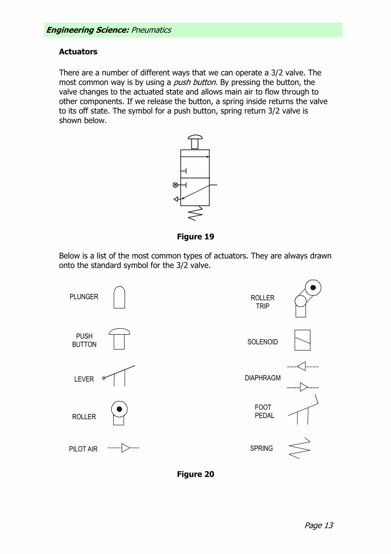
There are a number of different ways that we can operate a 3/2 valve. The most common way is by using a push button. By pressing the button, the valve changes to the actuated state and allows main air to flow through to other components. If we release the button, a spring inside returns the valve to its off state. The symbol for a push button, spring return 3/2 valve is shown below.
Figure 19 Below is a list of the most common types of actuators. They are always drawn onto the standard symbol for the 3/2 valve.
PLUNGER
PUSHBUTTON
LEVER
ROLLER
ROLLERTRIP
SOLENOID
PILOT AIR
DIAPHRAGM
SPRING
FOOTPEDAL
Figure 20
Engineering Science: Pneumatics
Page 14
Simple circuits using single-acting cylinders
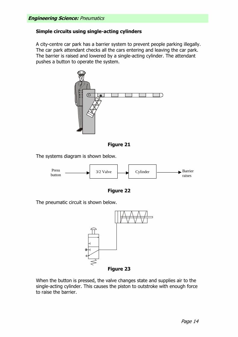
A city-centre car park has a barrier system to prevent people parking illegally. The car park attendant checks all the cars entering and leaving the car park. The barrier is raised and lowered by a single-acting cylinder. The attendant pushes a button to operate the system.
Figure 21 The systems diagram is shown below.
3/2 ValvePress
buttonBarrier
raisesCylinder
Figure 22 The pneumatic circuit is shown below.
Figure 23
When the button is pressed, the valve changes state and supplies air to the single-acting cylinder. This causes the piston to outstroke with enough force to raise the barrier.

Page 15
Engineering Science: Pneumatics
Figure 24
When the button is released, the valve returns to its original state and the piston is able to instroke ready for the process to begin again. Assignment 3 (a) Build the circuit for raising and lowering the car park barrier. (b) Press the button on the valve and keep it pressed. Explain what happens. (c) Release the button and explain what happens. (d) Using the correct terminology, explain how the circuit operates to raise
and lower the barrier. (e) Sometimes the attendant needs to inform the drivers of where to park,
especially when it is very busy. The problem is that when he lets go of the button, the barrier begins to fall. Someone suggests changing the actuator on the 3/2 valve. What actuator could be used instead and how does this affect the way the circuit works?

Engineering Science: Pneumatics
Page 16
T-piece
A T-piece or T-connector is a very simple component that lets us split or divide airflow. It can be very useful if you want two cylinders to operate at the same time.
AIR OUT
AIR IN
AIR OUT
Figure 25 On circuit diagrams, the T-piece is identified by a dot.
T-piece
Figure 26
Page 17
Engineering Science: Pneumatics
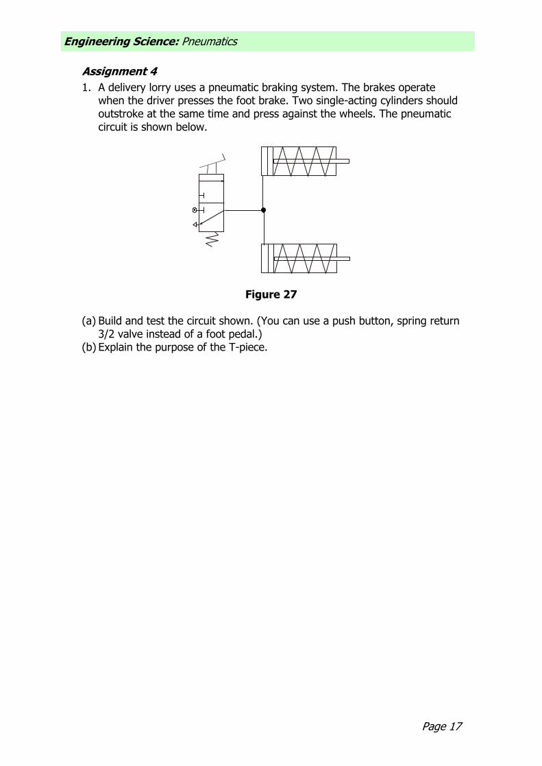
Assignment 4
1. A delivery lorry uses a pneumatic braking system. The brakes operate when the driver presses the foot brake. Two single-acting cylinders should outstroke at the same time and press against the wheels. The pneumatic circuit is shown below.
Figure 27 (a) Build and test the circuit shown. (You can use a push button, spring return
3/2 valve instead of a foot pedal.) (b) Explain the purpose of the T-piece.

Engineering Science: Pneumatics
Page 18
2. Four single-acting cylinders are used to clamp large nameplates to a table
to allow them to be engraved. All four cylinders must operate at the same time.
AIR SUPPLY
Figure 28 (a) Design a pneumatic system to solve this problem. (b) Build and test your solution. (c) Explain your choice of actuator.

Page 19
Engineering Science: Pneumatics
Simple circuits using double-acting cylinders
We know already that double-acting cylinders do not have a spring inside to return them to their original position. This means that we need to use compressed air to outstroke and instroke the piston. One way to do this is to connect a 3/2 valve to either side of the double-acting cylinder. Remember our car park problem. Someone has suggested changing the single-acting cylinder to a double-acting one.
Figure 29 The pneumatic circuit would now look like this.
Valve A Valve B
Figure 30 When the attendant actuates valve A by pressing the button, the double-acting cylinder outstrokes and lifts the barrier. It stays in this position until valve B is actuated. This allows the piston to instroke and the barrier is lowered.
Engineering Science: Pneumatics
Page 20
Assignment 5 (a) Build the circuit shown above for raising and lowering the barrier. (b) Press the button on valve A to outstroke the cylinder. Does the piston
instroke when you release the button? (c) Press the button on valve B. What happens to the cylinder? (d) What happens when you press both buttons at the same time? (e) Actuate valve A again and then try pushing against the piston. Why is it so
easy to move? (f) What type of problems could this cause in this particular circuit?
Page 21
Engineering Science: Pneumatics
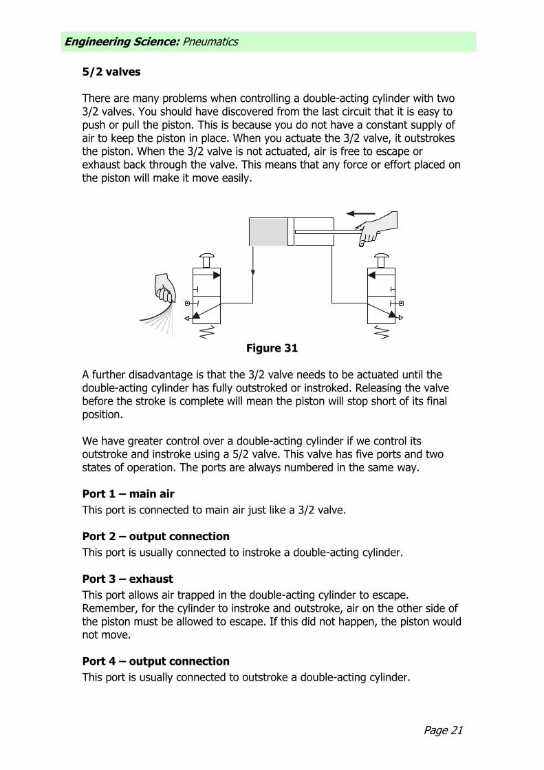
5/2 valves There are many problems when controlling a double-acting cylinder with two 3/2 valves. You should have discovered from the last circuit that it is easy to push or pull the piston. This is because you do not have a constant supply of air to keep the piston in place. When you actuate the 3/2 valve, it outstrokes the piston. When the 3/2 valve is not actuated, air is free to escape or exhaust back through the valve. This means that any force or effort placed on the piston will make it move easily.
Figure 31
A further disadvantage is that the 3/2 valve needs to be actuated until the double-acting cylinder has fully outstroked or instroked. Releasing the valve before the stroke is complete will mean the piston will stop short of its final position. We have greater control over a double-acting cylinder if we control its outstroke and instroke using a 5/2 valve. This valve has five ports and two states of operation. The ports are always numbered in the same way. Port 1 – main air
This port is connected to main air just like a 3/2 valve. Port 2 – output connection
This port is usually connected to instroke a double-acting cylinder. Port 3 – exhaust
This port allows air trapped in the double-acting cylinder to escape. Remember, for the cylinder to instroke and outstroke, air on the other side of the piston must be allowed to escape. If this did not happen, the piston would not move. Port 4 – output connection
This port is usually connected to outstroke a double-acting cylinder.

Engineering Science: Pneumatics
Page 22
Port 5 – exhaust
Again, this port lets the air on the other side of the piston escape. A 5/2 valve has two states of operation. One state supplies air to outstroke a double-acting cylinder and the other state will cause it to instroke.
State 1 instroke
In this state, the main air flows through the valve from port 1 to port 2. Any air within the cylinder is able to exhaust through the valve from port 4 to port 5. In this state, a 5/2 valve will cause a double-acting cylinder to instroke or hold the piston in the negative position. This means that air is always being supplied to the cylinder. Study the symbol below and ensure that you understand how the air flows through the valve.
1
2
3
4
5
AIR FROMCYLINDER
AIR TOCYLINDER
Figure 32
Page 23
Engineering Science: Pneumatics
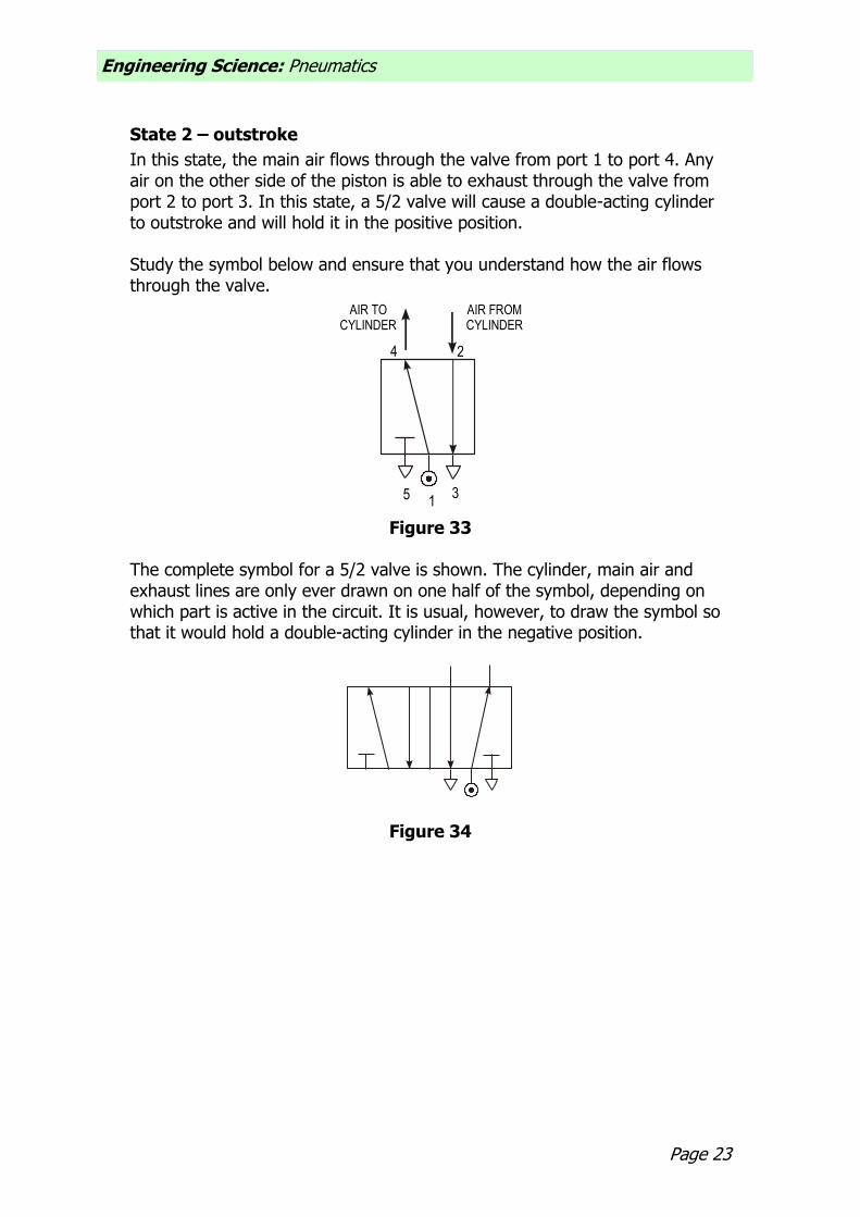
State 2 – outstroke
In this state, the main air flows through the valve from port 1 to port 4. Any air on the other side of the piston is able to exhaust through the valve from port 2 to port 3. In this state, a 5/2 valve will cause a double-acting cylinder to outstroke and will hold it in the positive position. Study the symbol below and ensure that you understand how the air flows through the valve.
1
2
3
4
5
AIR FROMCYLINDER
AIR TOCYLINDER
Figure 33
The complete symbol for a 5/2 valve is shown. The cylinder, main air and exhaust lines are only ever drawn on one half of the symbol, depending on which part is active in the circuit. It is usual, however, to draw the symbol so that it would hold a double-acting cylinder in the negative position.
Figure 34

Engineering Science: Pneumatics
Page 24
Pilot air
5/2 valves can be operated or actuated in the same way as 3/2 valves. However, the most common way of actuating a 5/2 valve is by pilot air. A pilot air 5/2 valve will change state when a brief air signal acts at either end of the valve. This signal is most often supplied from a 3/2 valve. In the example shown below, the button on valve A only needs to be pressed for a moment in order to change the state of the 5/2 valve. The 5/2 valve supplies the double-acting cylinder with air to make it outstroke.
Valve A
Figure 35 Notice that the pilot airlines to the 5/2 valve are drawn as broken or dashed lines to distinguish them from the other air lines in the circuit.
Page 25
Engineering Science: Pneumatics
Assignment 6
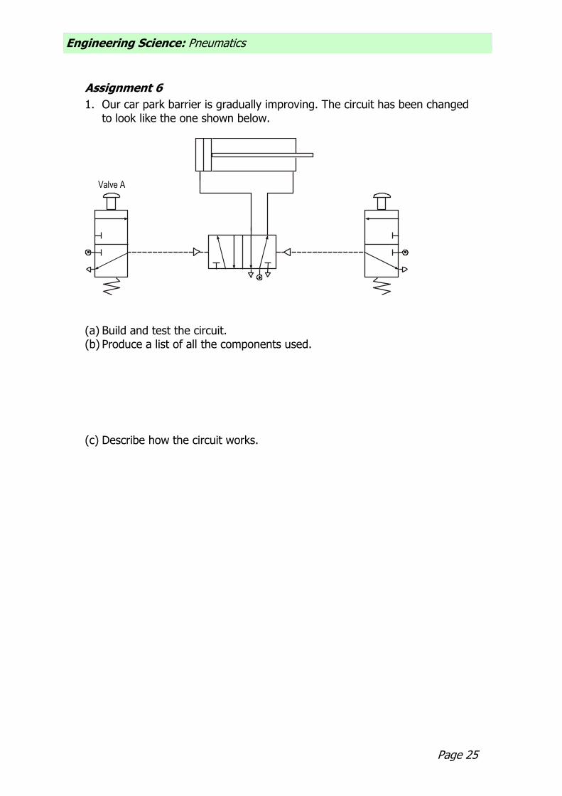
1. Our car park barrier is gradually improving. The circuit has been changed to look like the one shown below.
Valve A
(a) Build and test the circuit. (b) Produce a list of all the components used. (c) Describe how the circuit works.

Engineering Science: Pneumatics
Page 26
2. A door entry system is controlled by pneumatics. The system makes use of
a double-acting cylinder. Part of the circuit diagram is shown below.
A
B
C
Figure 36 (a) Name each of the components A, B and C. (b) Complete the diagram so that the door will open and close. (c) Describe how the circuit operates.

Page 27
Engineering Science: Pneumatics
Restrictors
You should have noticed in the circuits you have built so far that the pistons move very quickly. Sometimes this can be dangerous or it may prevent the circuit from working properly. To slow down the speed of a piston we use a restrictor.
There are two types of restrictor available to us. The first type is called a bi-directional restrictor (or sometimes a throttle valve). This valve works by reducing the amount of space that the air can flow through. We can adjust the airflow by turning the small screw on top of the valve. The symbol for a bi-directional restrictor is shown below.
Figure 40
This restrictor slows down the flow of air in both directions. This means that using only one extra component can slow both the outstroke and instroke of a cylinder. In the circuit shown below, the restrictor is used to slow down the speed of the single-acting cylinder. We can adjust this speed by turning the small screw on the top of the restrictor.
Figure 41 The problem with this type of restrictor is that it always slows down the speed of the piston in both directions. In many cases, we would only want either the outstroke or the instroke to be slowed down. Also, if we study the piston
movement very carefully, we sometimes find that it is quite jerky not
smooth as we would want it to be.

Engineering Science: Pneumatics
Page 28
Unidirectional restrictor To solve these problems we can use a component called a unidirectional restrictor. As its name suggests, it only slows down the air in one direction. The symbol is shown below.
1 2
Figure 42
When air flows into port 1 of the restrictor, some of the air takes the bypass route. A small ball is blown against a valve and blocks this path. The air is then forced to go through the restriction and this slows down the airflow.
AIR-FFLOW
RESTRICTION
BYPASS
1 2
Figure 43
When air flows into port 2 of the restrictor, again some of the air takes the bypass route. This time, the ball is blown away from the valve and the air passes through unrestricted.
AIR-
FLOW
RESTRICTION
BYPASS
1 2
Figure 44
In pneumatics, unidirectional restrictors are much more useful to us. However, we must always be careful to insert them in the circuit the correct way round.

Page 29
Engineering Science: Pneumatics
Remember our car park barrier. The attendant has complained that the barrier rises too quickly and is worried that this may damage it. Someone suggests changing the circuit to the one shown below.
Valve A Valve B
Figure 45 Study this circuit and take note of the position of the unidirectional restrictor. Is it where you expected? The restrictor is placed so that it slows down the exhaust air coming from the cylinder. When valve A is pressed, the 5/2 valve changes state and starts to supply the cylinder with air to make it outstroke. Air trapped on the other side of the piston escapes through the restrictor slowly. This makes the piston outstroke slowly. We always restrict the exhaust air coming from a cylinder as this makes the piston move much more smoothly.

Engineering Science: Pneumatics
Page 30
Assignment 8 1. Build and test the circuit shown on the previous page to raise the barrier
slowly. (a) Why do we restrict the exhaust air to slow down the speed of the
piston? 2. For safety reasons, the entrance door to a storeroom in a supermarket
must open and close slowly. A double-acting cylinder is used to slide the door.
Figure 46 A simplified circuit diagram is shown below with some of the piping missing.
Valve A Valve B
Figure 47
(a) Complete the diagram. (b) Build and test the circuit. (c) Explain why two restrictors are needed in this circuit.

Page 31
Engineering Science: Pneumatics
3. Part of a manufacturing process involves dipping components into a chemical solution to prepare them before they are painted.
Figure 48 A double-acting cylinder controls the process and for safety reasons the cylinder must outstroke and instroke slowly.
(a) Build and test a solution using components. (b) How well does your circuit operate? Why is it important that the
cylinder operates slowly?

Engineering Science: Pneumatics
Page 32
AND control
Although pneumatic circuits are very safe, it is important to take safety precautions. AND control circuits can be used to help prevent accidents by ensuring that guards are in position before machines are switched on. These circuits can also be used to stop a machine being switched on accidentally or to stop operators placing their hands in the machine when it is running.
SLIDINGDOOR
VALVEPOSITION
Figure 49 AND control involves connecting 3/2 valves together in series. This means that the output from one valve becomes the input to another. Study the diagram below.
Valve A Valve B
Figure 50 The single-acting cylinder will only outstroke when valve A and valve B are pressed at the same time. When the button on valve A is pressed, main air passes through and reaches valve B. The air cannot flow any further until valve B is pressed. This then supplies the cylinder with air and it outstrokes. We can summarise how the circuit behaves in a truth table.

Page 33
Engineering Science: Pneumatics
VALVE A
OFF
ON
OFF
ON
VALVE B
OFF
OFF
ON
ON
CYLINDER
INSTROKE
INSTROKE
INSTROKE
OUTSTROKE
Figure 51
Assignment 9
1. A company logo is to be stamped onto boxes using a single-acting cylinder. To prevent accidents, the machine will only work when the operator has both hands on the start buttons. If either button is released, the machine will stop.
BOX BOX BOX BOX
STAMP
Figure 52
(a) Design a circuit that would solve this problem. (b) Build and test your solution. (c) Draw a truth table of your results. (d) Explain how the circuit operates.

Engineering Science: Pneumatics
Page 34
2. Sometimes the operator manages to jam the buttons on so that he can
move some of the boxes on the conveyor belt. This is very dangerous and the manager wants the machine guarded. It should now only work when the guard is in position and the operator has both hands on the buttons. (a) Redesign the circuit to this specification. (b) Build and test your solution. (c) Explain how your solution works.

Page 35
Engineering Science: Pneumatics
OR control
Sometimes we need to control a pneumatic circuit from more than one position. This can be done using OR control circuits. These circuits are quite simple but they need another component called a shuttle valve. A shuttle valve is used to change the direction of air in a circuit. It has a small ball inside that gets blown from side to side. A picture is shown below.
FROMVALVE A
TO CYLINDER
FROMVALVE B
Figure 53 When air is supplied from valve A, the ball gets blown across and the air is directed towards the cylinder. When air is supplied from valve B, the ball is blown to the other side and again the air flows into the cylinder. If air comes from both directions, air still manages to reach the cylinder, as this is the only path it can take. The symbol for a shuttle valve is shown below.
Figure 54
OR control involves connecting 3/2 valves together in parallel. This means that either valve will outstroke the cylinder. Study the diagram below.
Valve A Valve B
Shuttle valve
Figure 55

Engineering Science: Pneumatics
Page 36
If the button on valve A is pressed, the ball in the shuttle valve is blown across towards B and the cylinder outstrokes. If the button on valve B is pressed, the ball is blown across towards A and the cylinder outstrokes. The circuit works if valve A or valve B is actuated. We can summarise the behaviour of this circuit in a truth table.
VALVE A
OFF
ON
OFF
ON
VALVE B
OFF
OFF
ON
ON
CYLINDER
INSTROKE
OUTSTROKE
OUTSTROKE
OUTSTROKE
Figure 56

Page 37
Engineering Science: Pneumatics
Assignment 10
1. Part of a production line involves a quality check. If goods are seen to be faulty then they are pushed off the conveyor by a single-acting cylinder. Two people are used to make sure that no faulty goods leave the factory. They operate the cylinder by pressing a button.
Figure 57
(a) Design a circuit to solve this problem. (b) Build and test your solution. (c) Draw a truth table of your results. (d) Someone has suggested changing the shuttle valve to a T-piece. Why
is this not a good idea? (You might want to build this circuit to investigate.)

Engineering Science: Pneumatics
Page 38
2. A bus door is operated by pneumatics. The door is operated by a single-acting cylinder and controlled by a 3/2 valve. In an emergency, there should be a second valve that allows passengers to open the doors.
Figure 58
(a) Design a circuit to solve this problem. (b) Build and test your solution. (c) Explain your choice of actuators.
Page 39
Engineering Science: Pneumatics
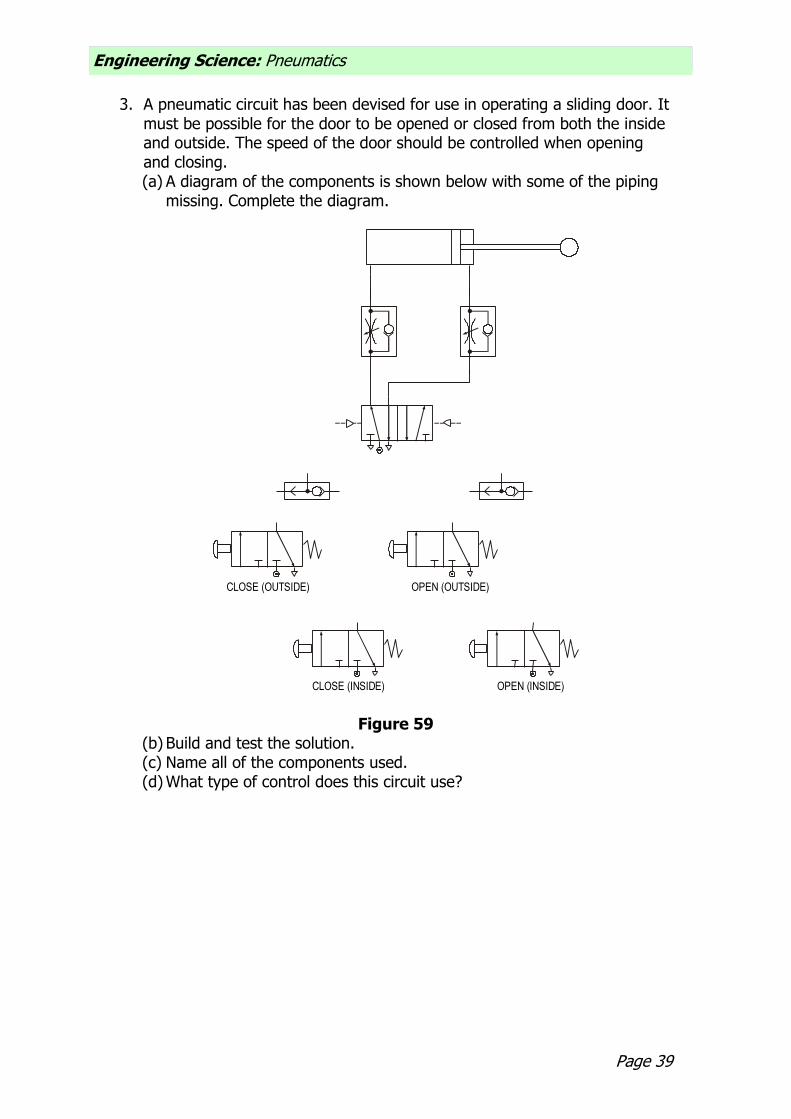
3. A pneumatic circuit has been devised for use in operating a sliding door. It must be possible for the door to be opened or closed from both the inside and outside. The speed of the door should be controlled when opening and closing. (a) A diagram of the components is shown below with some of the piping
missing. Complete the diagram.
CLOSE (OUTSIDE)
CLOSE (INSIDE)
OPEN (OUTSIDE)
OPEN (INSIDE)
Figure 59 (b) Build and test the solution. (c) Name all of the components used. (d) What type of control does this circuit use?

Engineering Science: Pneumatics
Page 40
Time delay
Sometimes in a circuit we want a pause or delay before something else happens. To create a delay we need to use two components – a unidirectional restrictor and a reservoir. A reservoir is simply an empty container, just like an empty bottle. The bigger the reservoir, the longer it takes to fill up with air. To make the delay longer we use a unidirectional restrictor in front of the reservoir. This slows down the air so that the reservoir takes even longer to fill. The length of time it takes to fill creates the delay.
Air
Figure 60 We can change the length of a delay by changing the size of the reservoir or adjusting the restrictor. Time delays can be very useful in clamping operations when objects need to be held in place by a cylinder for a specific amount of time to glue or set.
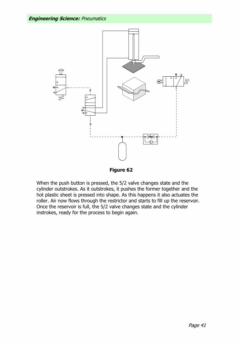
Figure 61 In this type of example the delay has to occur before the cylinder would instroke. Study the circuit diagram.
Page 41
Engineering Science: Pneumatics
Figure 62
When the push button is pressed, the 5/2 valve changes state and the cylinder outstrokes. As it outstrokes, it pushes the former together and the hot plastic sheet is pressed into shape. As this happens it also actuates the roller. Air now flows through the restrictor and starts to fill up the reservoir. Once the reservoir is full, the 5/2 valve changes state and the cylinder instrokes, ready for the process to begin again.

Engineering Science: Pneumatics
Page 42
Assignment 11 1. Build and test the circuit shown.
(a) Adjust the restrictor to achieve a time delay of three seconds. 2. Sand is fed into a hopper from above. When the hopper is full, the
operator presses the button and a double-acting cylinder slides open the door. This lets the sand fall into a wagon underneath. The operator now presses the other push button, but there must be a short delay before the hopper door closes to ensure that all the sand has emptied out. Study the circuit diagram.
Valve A Valve B
Figure 63
(a) Which two components are needed to create a time delay?
(b) Insert these components into the circuit diagram. Build and test your solution to ensure that it works properly.
(c) What other improvements would you make to this circuit?

Page 43
Engineering Science: Pneumatics
3. Wonderful Worktops is a company that manufactures worktops for
kitchens. The worktops are made from Formica sheets glued onto chipboard. A pneumatically controlled clamp holds down the glued sheet for 10 seconds before releasing it automatically.
Figure 64
(a) Design a solution to this problem. (b) Build and test your solution. (c) Explain how the circuit operates.

Engineering Science: Pneumatics
Page 44
Air bleed
Sometimes with pneumatics we find that the actuators on valves can get in the way of the circuit. Also, some actuators need a big force to make them work and this is not always possible. There are different ways to overcome these problems and one of the most common is to use an air bleed. An air bleed is simply an open pipe that allows the air in the circuit to escape. This air must be at a low pressure, otherwise the pipe would ‘wave’ about and be dangerous. Air bleed circuits rely on a component called a diaphragm valve. This valve is capable of detecting small changes in air pressure. The valve works in the same way as other 3/2 valves; it is only the actuator that is new to us. The symbol is shown below.
Figure 65 The diaphragm is a piece of rubber stretched inside the valve. When air flows into the top of the valve, the rubber expands much in the same way as when a balloon is blown up. When the diaphragm expands, it presses down inside the valve and changes its state. The signal to the diaphragm comes from an air bleed. When the air bleed is blocked, air is diverted back towards the diaphragm. This actuates the 3/2 valve and the cylinder outstrokes. Notice that the airflow to the air bleed passes through a restrictor. This slows down the air before it is allowed to escape.

Page 45
Engineering Science: Pneumatics
Figure 66
Engineering Science: Pneumatics
Page 46
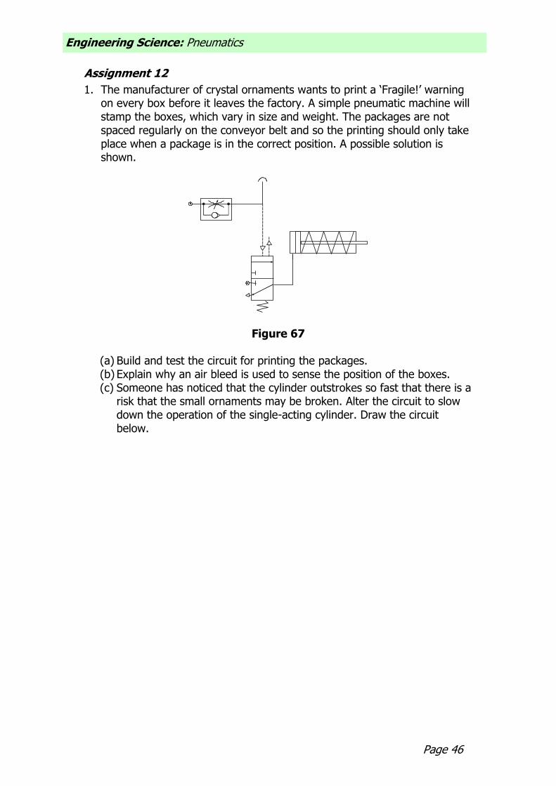
Assignment 12
1. The manufacturer of crystal ornaments wants to print a ‘Fragile!’ warning on every box before it leaves the factory. A simple pneumatic machine will stamp the boxes, which vary in size and weight. The packages are not spaced regularly on the conveyor belt and so the printing should only take place when a package is in the correct position. A possible solution is shown.
Figure 67
(a) Build and test the circuit for printing the packages. (b) Explain why an air bleed is used to sense the position of the boxes. (c) Someone has noticed that the cylinder outstrokes so fast that there is a
risk that the small ornaments may be broken. Alter the circuit to slow down the operation of the single-acting cylinder. Draw the circuit below.

Page 47
Engineering Science: Pneumatics
2. Crates containing cans of beans are moved to the dispatch area by a
series of conveyor belts. The crates are quite heavy and two single-acting cylinders are needed to push the crates from one belt to another.
AIR BLEED
Figure 68
(a) Design a pneumatic circuit to solve this problem. (b) Build and test your solution. Draw it below (c) Why is pneumatics often used in food production lines?

Engineering Science: Pneumatics
Page 48
Automatic circuits
Automatic circuits are commonly found on production lines. They help to speed up production and make sure that the goods are all manufactured to the same standard. There are two types of automatic circuit: semi-automatic and fully automatic. Semi-automatic
A semi-automatic circuit is one that completes a process once it has been started, usually by a human operator. We have come across semi-automatic circuits already in the course. You should recognise the two circuits shown below.
Circuit 1
Circuit 2
Figure 69

Page 49
Engineering Science: Pneumatics
Fully automatic A fully automatic circuit is one that continues to work, performing a task over and over again. It does not stop or wait for input from an operator. These circuits make use of actuators such as a roller trip and plunger to detect the position of the piston as it instrokes and outstrokes. Automatic circuits produce reciprocating motion. This is motion up and down like the needle on a sewing machine. It can also be left and right, or forwards and backwards along a straight line. We can represent reciprocating motion by arrows like these: For example, a polishing machine requires the reciprocating motion of a double-acting cylinder.
Figure 70
Figure 71 The pneumatic circuit is shown below.
Valve A Valve B
XY
Figure 72
As the piston instrokes, it trips valve A and the 5/2 valve changes state and the piston is sent positive. When it is fully outstroked, it trips valve B and the

Engineering Science: Pneumatics
Page 50
5/2 valve returns to its original position, allowing the piston to instroke. The process begins all over again and continues to operate. Assignment 13
1. Build and test the circuit for the polishing machine. (a) You should have noticed that the only way to stop the circuit is to turn
off the main air supply. It would be much better if we could use a lever-operated 3/2 valve to do this. It has been suggested that the valve be placed at either point X or point Y. Try both positions and record what happens.
(b) Which position do you think is better and why?
(c) Why must a lever-operated 3/2 valve be used?
Page 51
Engineering Science: Pneumatics
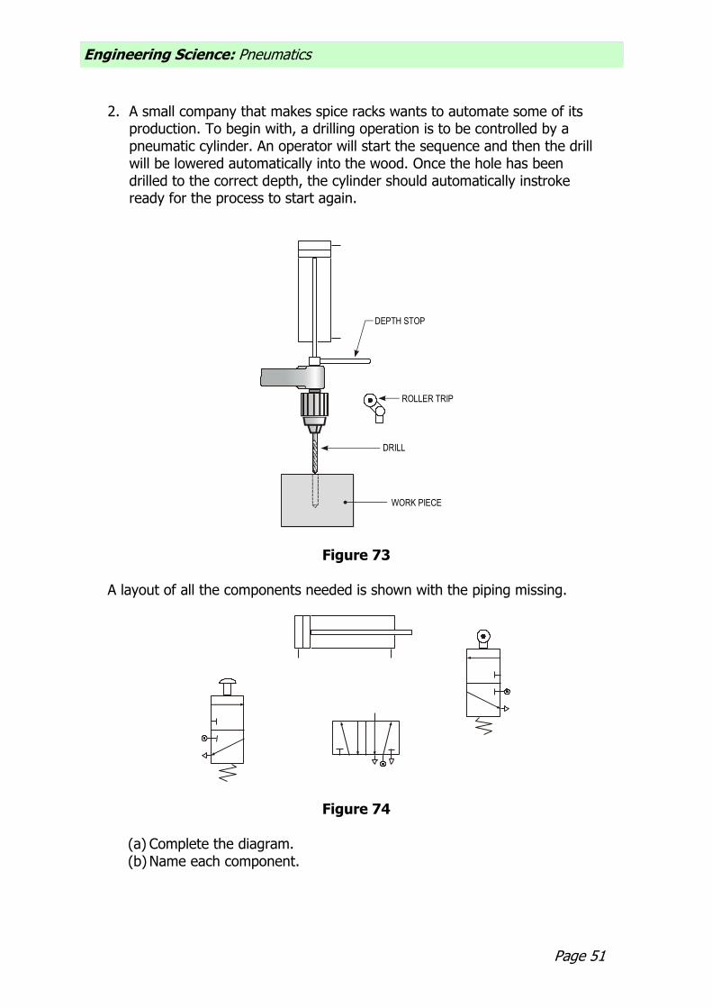
2. A small company that makes spice racks wants to automate some of its
production. To begin with, a drilling operation is to be controlled by a pneumatic cylinder. An operator will start the sequence and then the drill will be lowered automatically into the wood. Once the hole has been drilled to the correct depth, the cylinder should automatically instroke ready for the process to start again.
DEPTH STOP
ROLLER TRIP
DRILL
WORK PIECE
Figure 73 A layout of all the components needed is shown with the piping missing.
Figure 74
(a) Complete the diagram. (b) Name each component.
Engineering Science: Pneumatics
Page 52
(c) Build and test your solution. (d) The cylinder outstrokes far too quickly and the drill bits keep breaking.
Alter the circuit so that the cylinder outstrokes slowly.
Page 53
Engineering Science: Pneumatics
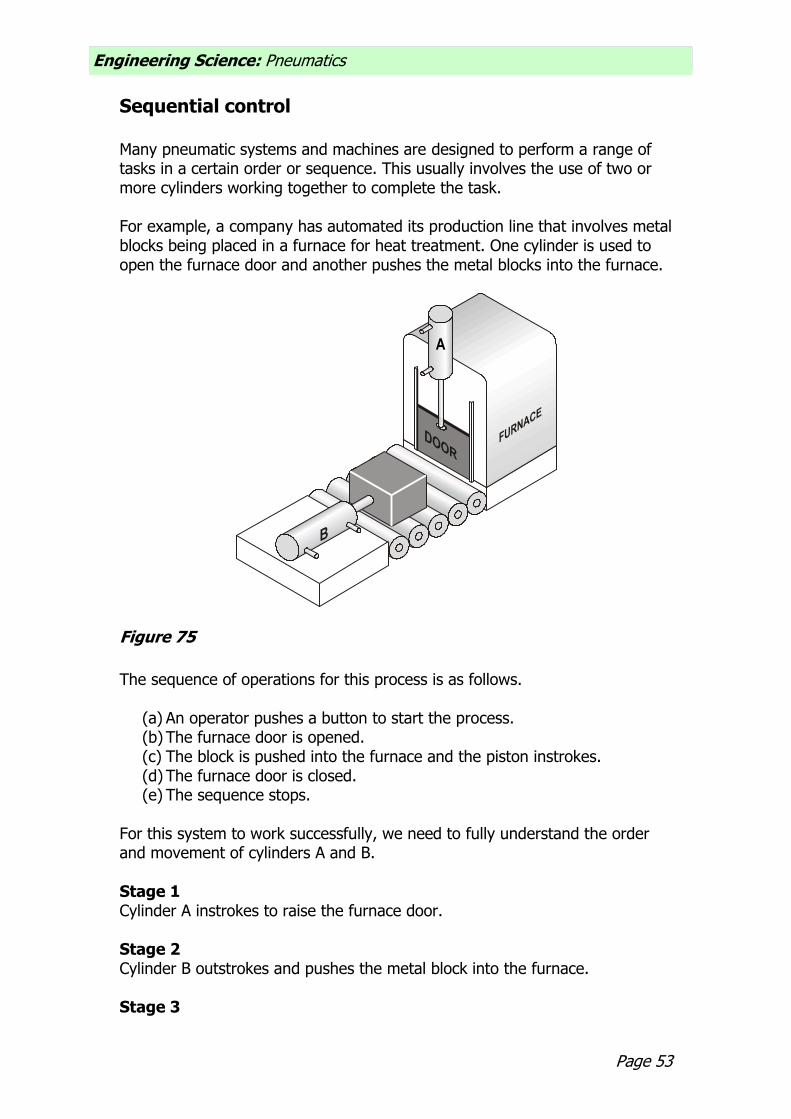
Sequential control Many pneumatic systems and machines are designed to perform a range of tasks in a certain order or sequence. This usually involves the use of two or more cylinders working together to complete the task. For example, a company has automated its production line that involves metal blocks being placed in a furnace for heat treatment. One cylinder is used to open the furnace door and another pushes the metal blocks into the furnace.
A
Figure 75
The sequence of operations for this process is as follows.
(a) An operator pushes a button to start the process. (b) The furnace door is opened. (c) The block is pushed into the furnace and the piston instrokes. (d) The furnace door is closed. (e) The sequence stops.
For this system to work successfully, we need to fully understand the order and movement of cylinders A and B. Stage 1 Cylinder A instrokes to raise the furnace door. Stage 2 Cylinder B outstrokes and pushes the metal block into the furnace. Stage 3
Engineering Science: Pneumatics
Page 54
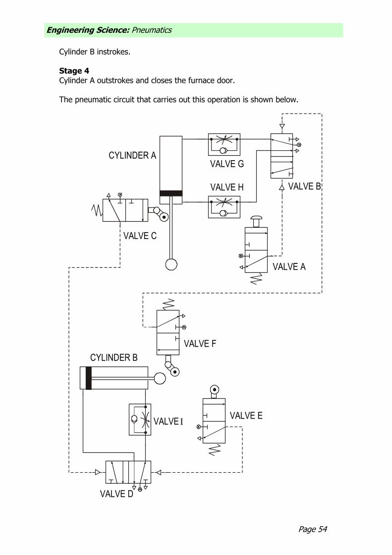
Cylinder B instrokes. Stage 4 Cylinder A outstrokes and closes the furnace door. The pneumatic circuit that carries out this operation is shown below.
CYLINDER B
CYLINDER A
VALVE A
VALVE B
VALVE C
VALVE D
VALVE E
VALVE F
VALVE G
VALVE H
VALVE I

Page 55
Engineering Science: Pneumatics
Figure 76
The system begins by actuating valve A. This changes the state of valve B and causes cylinder A to instroke, raising the door. When fully instroked, or negative, the piston trips valve C and this sends a signal to valve D. This 5/2 valve changes state and sends cylinder B positive. When fully outstroked, the piston trips valve E and the cylinder instrokes. When negative, valve F is actuated and causes cylinder A to outstroke and stay in the positive position. The system stops and waits for a signal from valve A. We can summarise the sequence of this circuit as follows.
Start, A, B+, B, A+, Stop
Assignment 14
1. Study this sequential circuit. (a) Name the components labelled Valve D, Valve F and Valve H.
(b) If Valve H were removed from the circuit, explain the effect this would have on the operation of the furnace door.
(c) Using appropriate terminology, explain how the circuit operates, starting, from when Valve A is pressed.
(d) A short delay is required before Cylinder B goes positive. Redraw the circuit to take this into account.

Engineering Science: Pneumatics
Page 56
2. A pneumatic system is used to transfer packages between conveyor belts
as shown. The pneumatic circuit is also shown.
Cylinder A
Cylinder B
Valve 1
Figure 77
The sequence of operation of the cylinders is A+, B+, A, B.
CYLINDER A CYLINDER B
1
2
3 4
5
6
Figure 78
(a) Build and test this circuit.
Page 57
Engineering Science: Pneumatics
(b) Name valves 1, 2 and 4.
(c) Describe how the circuit operates.
(d) If the packages were too light to actuate valve 1, describe another way to detect the packages.
(e) The outstroke speed of the cylinders needs to be slowed down. Describe how you would do this.

Engineering Science: Pneumatics
Page 58
Forces in a single-acting cylinder
When a single-acting cylinder outstrokes, it produces a force. We can use this force to carry out tasks. When we are designing pneumatic circuits, we must use a cylinder that is capable of completing its task. For example, if a single-acting cylinder is used to push parcels off a conveyor belt, then it must produce a big enough force to be able to do this. If the force is not big enough, then the parcels will not move, and if the force is too big, the parcels may be damaged. The size of the force produced by the cylinder as it outstrokes depends on
two things the air pressure supplied to the cylinder and the surface area of the piston. This means that if we want a bigger force we can either use a larger piston or increase the air pressure. However, it is not a good idea to increase the air pressure because this can damage components. The instroke of a single-acting cylinder is controlled by a spring. The spring returns the piston to its original position. We do not normally use the instroke of a single-acting cylinder to carry out tasks.

Page 59
Engineering Science: Pneumatics
Pressure Air pressure is measured in bars or in N/mm2 (newtons per square millimetre). We can measure the pressure in a pneumatic system using a pressure gauge. A gauge will always be connected to the compressor, but other gauges may be connected throughout large systems. This helps to detect leaks, as the pressure in the system would begin to fall if air was escaping from the pipes. Whenever we use pressure in calculations, we require the units to be in N/mm2. This sometimes means converting from bars to N/mm2. This conversion is easy, as you simply divide the value in bars by 10. For example, if the pressure supplied to a system is 5 bars, we can find the equivalent value in N/mm2 by simply dividing 5 by 10. Therefore, the value would be 0.5 N/mm2. The chart below provides a quick reference.
0
0
1 2 3 4 5 6 7 8 9 10
0.1 0.2 0.3 0.4 0.5 0.6 0.7 0.8 0.9 1
bar
N/mm2
Figure 79

Engineering Science: Pneumatics
Page 60
Area
The surface area of the piston is the area that the air pushes against to outstroke the piston. This area is circular.
Figure 80 The area of a circle is calculated using the formula
4
22 d
rArea
where r is the radius and d is the diameter of the circle.

Page 61
Engineering Science: Pneumatics
Force
The force produced when a single-acting cylinder outstrokes is calculated using the formula:
Force = Pressure Area where force is measured in newtons (N), pressure is measured in N/mm2 and area is measured in mm2. In some situations, we would know the size of the force needed to do a job properly. In this case, we would want to calculate the pressure needed or the size of the piston. To do this we need to rearrange our formula.
Pressure = Force Area
Area = Force Pressure
Worked example
Air is supplied to a single-acting cylinder at a pressure of 4 N/mm2. The diameter of the piston is 25 mm. Calculate the force produced as the piston outstrokes. Step 1
Write down any information that you have from the question. Pressure = 4 N/mm2
Diameter = 25 mm Step 2
We need to calculate the surface area.
2
2
2
mm491
4
2514.3
4
d
Area
Step 3
Use the correct formula for what you are trying to find. In this case, calculate the force.
Force = Pressure Area
= 4 491

Engineering Science: Pneumatics
Page 62
= 1964 N Force = 1.96 kN
Assignment 15
1. Write down the formula that we use to calculate the force in a single-acting cylinder as it outstrokes.
2. A pneumatic stamping machine is used to stamp the company logo onto
metal casings. It is discovered that the stamp does not imprint the logo properly. Suggest ways of increasing the size of the force produced by the cylinder.
3. What controls the instroke of a single-acting cylinder? 4. A single-acting cylinder is used to press two sheets of acrylic together
when they are gluing. The process requires a force of 300 N. The only piston available has a diameter of 20 mm and it is supplied with air at a pressure of 0.3 N/mm2. Will this arrangement enable this process to be carried out properly?
5. What force will be produced by a 20 mm diameter cylinder as it goes
positive using a pressure of 0.8 N/mm2?

Page 63
Engineering Science: Pneumatics
6. Calculate the outstroke force produced by a 40 mm diameter cylinder
when it operates with a supply pressure of 3 bars. 7. Write down the formula that we would use to calculate the pressure of a
system if we already knew the force required and the size of the cylinder available.
8. A stamping machine exerts a force of 454 N with a piston diameter of 34
mm. Calculate the air pressure required for this operation. 9. A machine that places tops on bottles uses a single-acting cylinder. The
process requires a force of 650 N. What air pressure needs to be supplied to the cylinder with a diameter of 56 mm?
10. A force of 540 N is needed to push a packing case off a conveyor belt. The
single-acting cylinder used has a diameter of 60 mm. What air pressure should be supplied to the system?

Engineering Science: Pneumatics
Page 64
11. A pneumatic system is used to test the quality of drawer guides in kitchen
cabinets. A force of 16 N is needed to open the drawer. The single-acting cylinder available has a piston diameter of 10 mm. What air pressure should be supplied?
12. Write down the formula we would use to find the area of a piston if we
already knew the size of the force it needed to produce and the air pressure being supplied.
13. A single-acting cylinder is used to lift parcels on to a conveyor. This
requires a force of 180 N with the system operating at a pressure of 6 bars. Calculate the area of the piston required.
14. A door requires a force of 400 N to slide it open. A single-acting cylinder
supplied with a pressure of 5 bars controls the operation. Calculate the diameter of the piston required to produce this force.
Use the formula:
AreaDiameter
4
Page 65
Engineering Science: Pneumatics
15. A furnace door weighs 100 N and is lifted by a single-acting cylinder as it outstrokes. Compressed air is supplied at a pressure of 4 bars. Calculate the diameter of the piston required to raise the door.
Use the formula:
AreaDiameter
4

Engineering Science: Pneumatics
Page 66
Forces in a double-acting cylinder
We already know that a double-acting cylinder can be much more useful to us in pneumatics because both the outstroke and instroke are controlled by compressed air. This allows us to make use of both the outstroke and the instroke force. What we learn, however, is that the outstroke force is greater than the instroke force. Why is this the case? During the outstroke, the compressed air pushes against the surface area of the piston in the same way as in the single-acting cylinder.
Figure 81
However, during the instroke the surface area is reduced because of the piston rod. This means that the compressed air does not have as big an area to push against and so it does not produce as big a force.
Figure 82
We can find this surface area, or effective area as it is known, by calculating the area of the piston rod and subtracting it from the surface area of the piston.
Effective area = piston area – piston rod area

Page 67
Engineering Science: Pneumatics
Worked example
A double-acting cylinder has a piston with a diameter of 25 mm. The piston rod is 5 mm in diameter. Pressure is supplied to the system at 4 N/mm2. Calculate the force produced by the cylinder as it outstrokes and instrokes. Step 1
Write down any information that you have from the question. Pressure = 4 N/mm2 Piston diameter = 25 mm Piston rod diameter = 5 mm Step 2
We need to calculate the surface area.
2
2
2
mm491
4
2514.3
4
d
Area
Step 3
Use the correct formula for what you are trying to find. In this case, calculate the outstroke force.
Force = Pressure Area
= 4 491
= 1964 N Outstroke force = 1.96 kN Step 4
Calculate the piston rod area.
2
2
2
mm20
4
514.3
4
d
arearodPiston
Step 5
Calculate the effective area. (We already know the piston area from step 2.)
2mm471
20491
arearodpistonareapistonareaEffective
Engineering Science: Pneumatics
Page 68
Step 6
Calculate the instroke force. Force = Pressure Effective Area
= 4 471 = 1884 N Instroke force = 1.88 kN Assignment 16 1. Explain why the forces produced by a double-acting cylinder on the
outstroke and instroke are different. 2. A double-acting cylinder found in a Technological Studies room has a
piston diameter of 20 mm and is supplied with air at a pressure of 0.3 N/mm2. What force is produced as the piston outstrokes? The piston rod has a diameter of 6 mm. What force is produced on the instroke?
3. A double-acting cylinder is used to raise and lower a barrier in a car park.
The air pressure is 0.4 N/mm2 and the piston has a diameter of 40 mm. The piston rod is 12 mm in diameter. What forces are produced when the piston outstrokes and instrokes?

Page 69
Engineering Science: Pneumatics
4. A double-acting cylinder is used to set up skittles in a bowling complex. An
instroking force of 0.04 kN is needed to move the skittles. The effective area of the piston is 133 mm2. (a) What pressure should be supplied to the cylinder? (b) At this pressure, will the outstroke force be larger or smaller than the
instroke? Explain your answer. 5. Components on a conveyor system travel along and drop onto a table
attached to the end of a double-acting cylinder.
Figure 83 As the cylinder instrokes, the components are raised up and then pushed by another cylinder on to the next conveyor. The piston diameter is 20
Engineering Science: Pneumatics
Page 70
mm and air is supplied at a pressure of 0.45 N/mm2. The effective area is 200 mm2. (a) Calculate the instroke force and say whether the system could lift a
component weighing 100 N.
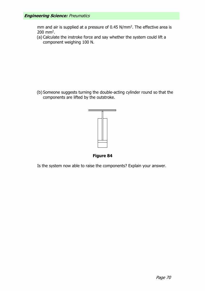
(b) Someone suggests turning the double-acting cylinder round so that the components are lifted by the outstroke.
Figure 84
Is the system now able to raise the components? Explain your answer.

Page 71
Engineering Science: Pneumatics
Section 2: Electronic Control There are many advantages in controlling pneumatic circuits with electronics. First, electronic signals are faster than pneumatic signals, so circuits respond much more quickly. We can also carry electrical signals over longer distances than pneumatic signals. Finally, electronic components are much smaller than pneumatic actuators, which can be bulky and interfere with the operation of a circuit. If we control pneumatic circuits with electronics we can design complicated control systems and still use pneumatic components for lifting and moving and all the things that they do best. To control a pneumatic circuit with electronics we need to use a solenoid-operated valve.
Figure 93
This type of valve works in the same way as other 3/2 or 5/2 valves with the exception that it is actuated by an electrical signal. This electrical signal can be produced by many different components such as microswitches and reed switches. Reed switches are useful if the cylinder has a magnetic piston band. This means that you can detect the position of the piston without relying on a switch or button that needed to be pressed. Most solenoids are 8 V or 12 V devices. The voltage rating will be stamped or printed onto the solenoid casing. You must always check this before you start work with solenoids. To find out more information about solenoids, you should look at video clips within the Festo CD-ROM. In particular, you should view film numbers 8, 9 and 10.
In a bottling plant, a single-acting cylinder is used to press the lids onto the bottles. A roller trip, spring return 3/2 valve is used to detect when the bottles are in the correct position. Sometimes, however, the roller is not actuated and the bottles pass to the next stage unsealed. Someone suggests that a microswitch be used instead to sense when the bottles are in place.

Engineering Science: Pneumatics
Page 72
Figure 94
The circuit diagram would look like this:
V+
0 V
Figure 95 V+ will depend on the voltage rating of your solenoid. This will usually be 8 V or
12 V. You should check this before wiring your circuit.
To get the single-acting cylinder to outstroke, you press the microswitch. This energises the solenoid valve and it changes state. The valve then allows air to flow into the cylinder. Once the switch is released, the cylinder instrokes. It is important that you do not keep the switch pressed for a long time as this can cause the solenoid to overheat and be damaged.
Page 73
Engineering Science: Pneumatics
Assignment 17 1. Build and test the circuit shown for pressing the lids onto bottles.
(a) Record all the important information about this circuit, including a systems diagram, a circuit diagram and an explanation of how the circuit works.
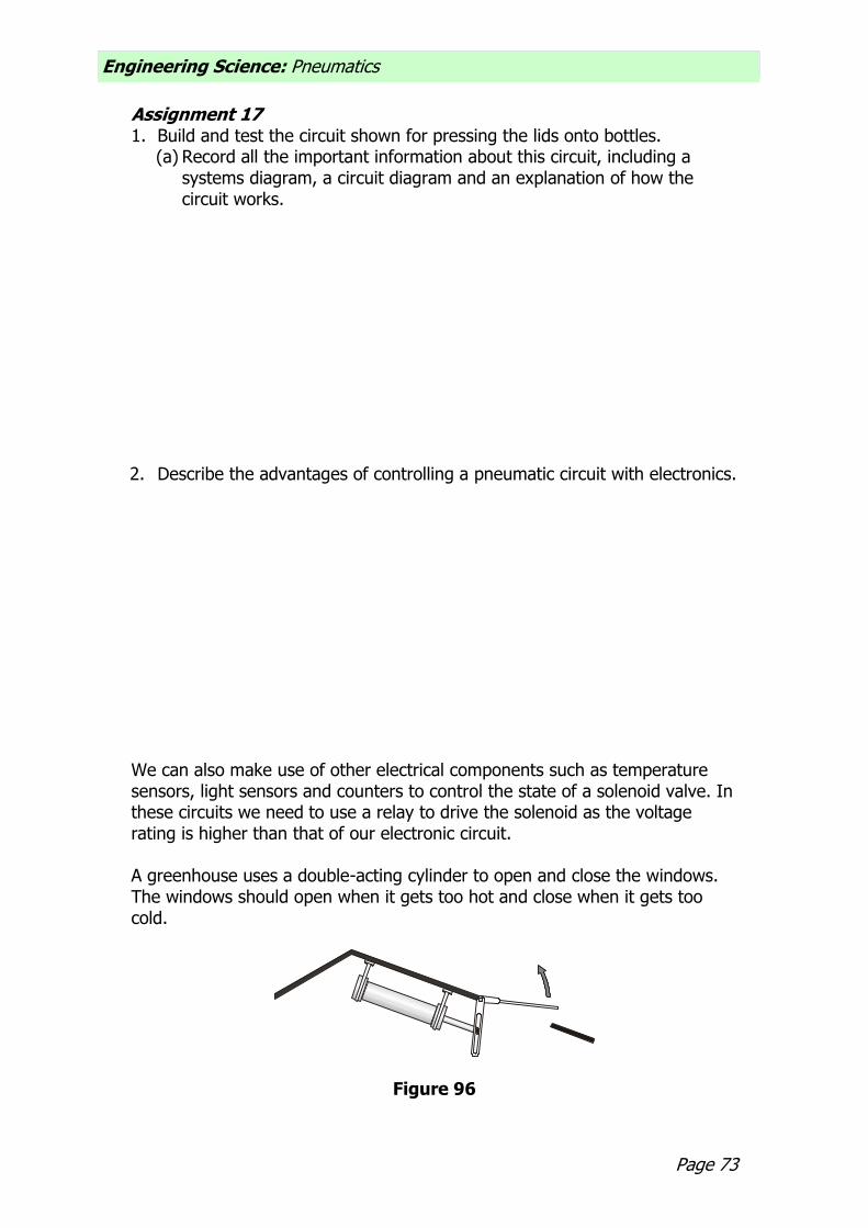
2. Describe the advantages of controlling a pneumatic circuit with electronics. We can also make use of other electrical components such as temperature sensors, light sensors and counters to control the state of a solenoid valve. In these circuits we need to use a relay to drive the solenoid as the voltage rating is higher than that of our electronic circuit. A greenhouse uses a double-acting cylinder to open and close the windows. The windows should open when it gets too hot and close when it gets too cold.
Figure 96

Engineering Science: Pneumatics
Page 74
The circuit diagram to solve this problem is shown below.
POS
SIG
0V
NEG
RANGE+5V DC TO +8V
DC
+
S
0V
-
+
S
0V
-
E & L INSTRUMENTS Ltd
TP
+V
0V
0V
+
S
0V
-
+
S
0V
-
E & L INSTRUMENTS Ltd
TP
WITH
REF VOLT S
REF
INC
REF VOLT S
VREF
0V
MAGIC
THINGY
+
S
0V
-
+
S
0V
-
E & L INSTRUMENTS Ltd
TP
0v
0v
+V
0V
+
S
-0V
+
S
-
E & L INSTRUMENTS Ltd
Vs
Figure 97
Assignment 18
1. Build and test the circuit shown for opening and closing the window. (a) Record all the important information about this circuit including a circuit
diagram and an explanation of how it works. (b) The window opens and closes too quickly. Alter your circuit so that it
moves slowly.

Page 75
Engineering Science: Pneumatics
Section 3: Programmable Control To achieve really complex control of pneumatics, it is much easier and more reliable to use a programmable system. One way is to use a microcontroller such as the Basic Stamp. Using this type of interface allows us to control the state of a solenoid valve. A solenoid valve is actuated by a brief electrical signal and should only really be used for signalling purposes. If the solenoid is energised for too long, the valve can overheat and be permanently damaged. Programmable control allows us to design sequences that are not possible
with pneumatic actuators, for example the sequence B+, A+, A, B. It also allows us to control the action of a solenoid by more than one switch and this could be very useful as part of a safety system. Exact time delays can be achieved too without the need for components such as a flow control valve and a reservoir. The greatest advantage, however, is that we can change the program at any time. In fact, we could have several programs written and saved on disc ready to be used. Let us look back at our car park problem.
Figure 98 Finally someone has suggested that the barrier should be controlled by a computerised system as this will help to speed up the flow of traffic entering the car park, especially when it is very busy. When cars approach the barrier, the car wheels will activate a switch and the barrier will rise automatically. Once the car has passed under the barrier, a second switch is pressed that lowers the barrier. The process is then ready to begin again.

Engineering Science: Pneumatics
Page 76
The flow chart is shown below.
START
Barrier
down
Is approach
switch
pressed?
Barrier
up
Is ‘clear’
switch
pressed?
Yes
No
Yes
No
Figure 99 A PBasic program that would achieve this operation is: init: let dirs = %11110000
main: low 7
check1:if pin0 = 1 then raise goto check 1
raise:high 7
if pin1 = 1 then main
goto raise
end
To test this program you will need to download it to a stamp controller. You will also need the input module and output driver module. The input module allows us to connect switches and sensors to the stamp controller. For this problem we need to connect two microswitches to the input module at pins 0 and 1.

Page 77
Engineering Science: Pneumatics
The output driver allows the stamp controller to drive devices such as buzzers and motors. In this problem it will be used to control a solenoid 3/2 valve. The solenoid needs its own power supply to energise the coil. Most solenoids are 8 V or 12 V devices and the casing of the component should tell you the voltage rating. This voltage should be applied to the ‘driver power supply’ terminals at the top of the board. You must also make sure that the slide switch is set to ‘External’. Finally, connect the black wire from the solenoid to pin 7 and the red wire to the V+ connection.
V+
V+
7
6
5
4
RP1
STAMP EXTERNAL 0V V+
DRIVERPOWERSUPPLY
DARLINGTONDRIVER
SERVO
B
PUSHPULLDRIVER
A
B
0V
7
6
5
4
Red
Black
Power
supplySet switch to
External
Figure 100

Engineering Science: Pneumatics
Page 78
The finished circuit should look like this.
Stamp
Controller
Output
Driver
Input
Module
0V V+
Figure 101
Assignment
1. Build and test the circuit shown. Name two other types of input device that could be used to detect the cars. State one advantage and disadvantage of each.

Page 79
Engineering Science: Pneumatics
2. Sheet-metal drainage panels are shaped on a pneumatic press. The press
uses two single-acting cylinders, a T-piece and a 3/2 solenoid valve. The sequence must only begin when the start switch has been pressed. The press is then held for three seconds before being released. A buzzer must sound when the press is in operation. (a) Design a pneumatic circuit to solve this problem. (b) Draw a flow chart. (c) Write a PBasic program. (d) Evaluate your solution. How well does it solve the problem? (You may
need to build your solution to check this.)

Engineering Science: Pneumatics
Page 80
3. Modern trains have many built-in safety features. One feature is an
automatic brake system that is activated if the driver does not press a switch every 30 seconds. This is to ensure that the driver is alert throughout the journey. Five seconds before the brakes are applied automatically, a warning buzzer sounds to alert the driver that the switch needs to be pressed. Pressing the button at this stage will reset the system. Large forces are needed to bring the train to a stop and pneumatic cylinders are used to activate the brakes. (a) Using two single-acting cylinders, a T-piece and a 3/2 solenoid valve,
design a pneumatic circuit that could be used to apply the brakes. (b) Draw a flow chart of this problem. (c) Write a PBasic program that would control the pneumatic circuit. (d) Build and test your solution. (e) Evaluate your solution. How well does it solve the problem? (f) As the train approaches a station, the driver needs to apply the brakes
to stop the train. Change your original program to allow for this.
Page 81
Engineering Science: Pneumatics

Engineering Science: Pneumatics
Page 82

Page 83
Engineering Science: Pneumatics