PNEUMATIC SPOOL VALVE ISLANDS VDMA 24563 ISO 02 - ISO … · 5 INSTALLATION OUTPUT INPUT INPUT 24V...
62
5 3 1 0 2 4 6 1 3 5 7 INPUT 0 2 4 6 1 3 5 7 INPUT + 5V + 24V RUN/MOD ERR/NET 0 2 4 6 1 3 5 7 INPUT 0 2 4 6 1 3 5 7 INPUT Installation manual MS-P588-3.GB.R4a (3839353) MODBUS PNEUMATIC SPOOL VALVE ISLANDS VDMA 24563 ISO 02 - ISO 01 (G1/8 - G1/4) designed for connection to a PLC by field bus and the following protocols: PROFIBUS-DP, INTERBUS-S, DEVICE NET, WORLDFIP / FIPIO and MODBUS BUSLINK - VDMA GB
Transcript of PNEUMATIC SPOOL VALVE ISLANDS VDMA 24563 ISO 02 - ISO … · 5 INSTALLATION OUTPUT INPUT INPUT 24V...

5
3
1
0246
1357
INPUT
0246
1357
INPUT
+ 5V
+ 24V
RUN/MOD
ERR/NET
0246
1357
INPUT
0246
1357
INPUT
Installation manual
MS-P588-3.GB.R4a(3839353)
MODBUS
PNEUMATIC SPOOL VALVE ISLANDSVDMA 24563 ISO 02 - ISO 01 (G1/8 - G1/4)
designed for connection to a PLC by fi eld bus and the following protocols:
PROFIBUS-DP, INTERBUS-S, DEVICE NET, WORLDFIP / FIPIO and MODBUS
BUSLINK - VDMA
GB

2
INSTALLATIONBUSLINK - VDMA
COPYRIGHT © 1999 - ASCO/JOUCOMATIC - All rights reserved.
CAUTION
To avoid malfunction of the bus system, please check on any valve island
• for correct addressing and speed parameters; • for correct wiring or connection of the terminating resistor for the bus at each end of the network when using
Profi bus-DP, Device Net, FIPIO and Modbus. All installation, adjustment and maintenance operations must be carried out by qualifi ed personnel.
NOTICE
The information in this manual is subject to change without notice.
In no event shall ASCO/JOUCOMATIC be liable for technical or editorial errors or omissions. Neither is any liability assumed for accidental or consequential damages arising out of or in connection with the supply or use of the informaton contained herein.
THIS MANUAL CONTAINS INFORMATION PROTECTED BY COPYRIGHT. NO PART OF THIS DOCUMENT MAY BE PHO-TOCOPIED OR REPRODUCED IN ANY FORM OR MANNER WHATSOEVER WITHOUT PRIOR WRITTEN PERMISSION FROM ASCO/JOUCOMATIC.
A separate Declaration of Incorporation in accordance with EEC-Directive 89/392/EEC Annex II B is available on request. Please provide acknowledgement number and serial numbers of products concerned.This product complies with the essential requirements of the EMC-Directive 89/336/EEC and amendments on electromagnetic compatibility. A Declaration of Conformity is available on request.

3
INSTALLATION BUSLINK - VDMACONTENTS Page
1. The BUSLINK-VDMA System _______________________________________________________________ 5 1.1 BUSLINK-VDMA with PROFIBUS-DP ________________________________________________ 6 1.2 BUSLINK-VDMA with INTERBUS-S __________________________________________________ 7 1.3 BUSLINK-VDMA with DEVICE NET __________________________________________________ 8 1.4 BUSLINK-VDMA with WORLDFIP-FIPIO ______________________________________________ 9 1.5 BUSLINK-VDMA with MODBUS _____________________________________________________ 102. System components _____________________________________________________________________ 11 2.1 Functional description ______________________________________________________________ 11 2.2 Description of BUSLINK ___________________________________________________________ 12 2.3 Dimensions - Mountings - Weights ____________________________________________________ 13 2.4 Ordering information for a BUSLINK-VDMA island ________________________________________ 14 2.5 VDMA ISO 02 - ISO 01 spool valves series 538 - 539 and pilot valves ________________________ 153. Assembly of BUSLINK-VDMA ______________________________________________________________ 16 3.1 Mounting _______________________________________________________________________ 16 3.2 Pneumatic connection ______________________________________________________________ 16 3.3 Manual override __________________________________________________________________ 184. Electrical connection ____________________________________________________________________ 19 4.1 General ________________________________________________________________________ 19 4.2 Voltage supply ____________________________________________________________________ 19 4.3 Connection of supply voltage ________________________________________________________ 20 4.4 Supply principles _________________________________________________________________ 21 4.5 Coupling and decoupling shunts of 24V DC power supplies ________________________________ 21 4.6 Connection of inputs _____________________________________________________________ 21 4.7 Fuses ________________________________________________________________________ 24 4.8 Addressing of inputs _______________________________________________________________ 245. PROFIBUS-DP ___________________________________________________________________________ 27 5.1 Bus connection to IP65 _____________________________________________________________ 27 5.2 Programming instructions ___________________________________________________________ 28 5.3 Startup of PROFIBUS-DP network ___________________________________________________ 32 5.4 Diagnostics _____________________________________________________________________ 32 5.5 Accessories for PROFIBUS-DP _____________________________________________________ 33 5.6 Dimensions of accessories for PROFIBUS-DP __________________________________________ 346. INTERBUS-S _____________________________________________________________________________ 35 6.1 Bus connection ___________________________________________________________________ 35 6.2 Programming instructions ___________________________________________________________ 37 6.3 Startup of INTERBUS-S network ____________________________________________________ 38 6.4 Diagnostics _____________________________________________________________________ 39 6.5 Accessories for INTERBUS-S _______________________________________________________ 40 6.6 Dimensions of accessories for INTERBUS-S ___________________________________________ 407. DEVICE NET ____________________________________________________________________________ 41 7.1 Bus connection __________________________________________________________________ 41 7.2 Programming instructions ___________________________________________________________ 43 7.3 Startup of DEVICE NET network ____________________________________________________ 44 7.4 Diagnostics _____________________________________________________________________ 46 7.5 Accessories for DEVICE NET _______________________________________________________ 47 7.6 Dimensions of accessories for DEVICE NET ___________________________________________ 488. FIPIO __________________________________________________________________________________ 49 8.1 Bus connection __________________________________________________________________ 49 8.2 Programming instructions ___________________________________________________________ 51 8.3 Startup of FIPIO network __________________________________________________________ 53 8.4 Diagnostics _____________________________________________________________________ 54 8.5 Accessories for FIPIO _____________________________________________________________ 55 8.6 Dimensions of accessories for FIPIO _________________________________________________ 569. MODBUS _______________________________________________________________________________ 57 9.1 Bus connection __________________________________________________________________ 57 9.2 Programming instructions ___________________________________________________________ 57 9.3 Startup of MODBUS network _______________________________________________________ 59 9.4 Diagnostics _____________________________________________________________________ 59 9.5 Accessories for MODBUS __________________________________________________________ 61 9.6 Dimensions of accessories for MODBUS ______________________________________________ 62Connector size 15 for the supply of a remote device _________________________________________________ 63

4
INSTALLATIONBUSLINK - VDMA

5
INSTALLATION
INPUTOUTPUT INPUT
24V =
1. The BUSLINK - VDMA system Pneumatic islands of 4 to 16 monostable or bistable spool valves to VDMA, ISO 02 (G1/8) - ISO 01 (G1/4), with integrated
connections for data exchange with a control system (PLC) by means of a fi eld bus and standardized protocol. Versions adapted to the following standardized communication protocols:
Spool valves (16 monostable or bistable spool valves at maximum)Module for bus connectionModule with 8 inputsModule with 16 inputs
1
2
3
4
BUSLINK - VDMA
MODBUSNTERFACE
N˚ 21401
See special ins-tallation manual
MS-P588-5
+ 5V
+ 24V
RUN/MOD
ERR/NET
2 14 3
0246
1357
0246
1357
BYTE
BYTE INPUT
0246
1357
BYTE
INPUT
INPUT
0246
1357
BYTE
3
CONNECTION STRUCTURE
PLC
Certif
ié-
Certified
-Z
ertifikat-N˚194
ADVANTAGESWith the many advantages it offers, the Buslink system meets modern needs for automated installations.• No bulky and diffi cult wiring.• Time and money saved due to direct electric cabling and common air supply.• Unit tested and equipped with spool valves at delivery.• Easy maintenance.
COMBINATIONSBuslink units can be grouped as follows:• Islands of 4, 6, 8, 10, 12, 14 or 16 monostable or bistable 5/2 or 5/3 spool
valves. It is possible to mix monostable and bistable spool valves (max. confi guration: 32 outputs).
• Differently sized islands for spool valve series 538 (ISO 02) - 539 (ISO 01) (only one valve size per island).
• Each island can be equipped with modules with 8 or 16 inputs (4 modules at maximum) which must be connected on the left side.
• Monostable and bistable spool valves with integrated push/pull pilot valves (E), all functions available on one island.
• Any confi guration possible upon request.
Max. 4 modulesMax. 32 inputs and 32 outputs
(D)(E)
The pilot valves size 15 (E) with pad mounting to CNOMO, E06.36.120N, are placed on the same side as the spool valves (D). The bistable spool valves are controlled by a new type of miniature solenoid valve with integrated push/pull pilot offering a compact solution as shown below.

6
INSTALLATION
1.1 PROFIBUS-DPPneumatic valve island for data exchange via fi eld bus and standardized Profi bus-DP protocol.The connection between a control system (PLC) and pneumatic spool valve islands by means of a fi eld bus with RS485 interface allows the transmission of data with a 2-wire cable:• control signals to the spool valves and additional outputs• information signals from the sensor inputs.
ADVANTAGESWith the many advantages it offers, the Buslink system meets modern needs for automated installations:• No bulky and diffi cult wiring.• Time and money saved due to direct electric cabling and com-
mon air supply.• Visual display and quick disconnection for easy maintenance.• Unit tested and equipped with spool valves at delivery.
COMBINATIONSBuslink units can be grouped as follows:• Modules for VDMA-type monostable or bistable spool valves,
5/2 or 5/3, ISO 02 (series 538 - G1/8) - ISO 01 (series 539 - G1/4).• Modules with 8 or 16 inputs. Any confi guration possible upon request
(only one valve size per island).
OPTIONS (consult us)• Island with air supplied at two different pressure rates.• Island with external air supply for pilot pressure.
COMMUNICATION CHARACTERISTICSCommunication protocol : PROFIBUS-DP
(DIN 19245 - part 3 - EN 50170)Transmission : shielded twisted pair, RS 485 interfaceBus structure : line or tree structure with repeatersMax. number of spool valve islands : 97 islands (121 participants)Number of valves per island : 4 to 16 spool valvesMax. number of inputs/outputs : 32 inputs and 32 outputs per island (including valve outputs)Max. bus cable length : 100 m - 1200 m, depending on the transmission speedTransmission speed : automatic selection from 9.6 KBaud to 12 MBaudIsland addressing (participants) : integrated rotary-type switchesCompatibility with control system : no modifi cation of current programsCompatible equipment : SIEMENS, BOSCH, etc.
ELECTRICAL CHARACTERISTICSSupply voltage : 24 V DC, ±10%. The outputs (valves) and the bus electronics/sensor inputs can be
supplied separately.Max. ripple ratio : 10 %Consumption per pilot valve : 50 mA (monostable spool valve), 79 mA (bistable spool valve)Consumption per input : 9 mACoil insulation class : FProtection : IP65Electrical insulation : optocouplersPeak voltage suppression : integrated in the island for each coil24 V supply connection : 4-pin male panel connector M18Bus connection (IN/OUT) : 5-pin male panel connector M12 (IP65) Option 01: protection to IP40 with 9-pin female SUB-D panel connectorInput connection : 5-pin female panel connector M12 or screw terminalsEarth connection : at supply connectorElectromagnetic compatibility : in accordance with EU directive EMC 89/336/EEC CE identifi cation
PNEUMATIC CHARACTERISTICSFluid : air or neutral gas, fi ltered at 30 µm, lubricated or notOperating pressure : 1.5 to 8 barFlow rate (Qv at 6 bar) series 538 : 500 l/min series 539 : 950 l/minAllowable temperature : +5°C to +50°C
0246
1357
INPUT + 5V
+ 24V
RUN/MOD
ERR/NET0246
1357
INPUT
INPUT
INPUTOUTPUT INPUT
2
2 2 2
2
2 2 2
24V =
24V =
INPUTOUTPUT
Repeater
For details on spool valves see P468
Repeater

7
INSTALLATION
1.2 INTERBUS-SPneumatic spool valve island for data exchange via fi eld bus and standardized INTERBUS-S protocol.The connection between a control system (PLC) and several spool valve islands by means of a fi eld bus with RS485 interface allows the transmission of the following data with a single 9-wire cable :• control signals to the spool valves and additional outputs• information signals from the sensor inputs.
ADVANTAGESWith the many advantages it offers, the Buslink system meets modern needs for automated installations:• No bulky and diffi cult wiring.• Time and money saved due to direct electric cabling and com-
mon air supply.• Visual display and quick disconnection for easy maintenance.• Unit tested and equipped with spool valves at delivery.
COMBINATIONSBuslink units can be grouped as follows:• Modules for VDMA-type monostable or bistable spool valves,
5/2 or 5/3, ISO 02 (series 538 - G1/8) - ISO 01 (series 539 - G1/4).• Modules with 8 or 16 inputs. Any confi guration possible upon request (only one valve size per island).
OPTIONS (consult us)• Island with air supplied at two different pressure rates.• Island with external air supply for pilot pressure.
COMMUNICATION CHARACTERISTICSCommunication protocol : INTERBUS-STransmission : shielded 3 x 2-wire cable, twisted in pairs, + 3 wires (2 forward, 2 return, 2 ground + 3 power supply wires), RS 485 interfaceBus structure : loopMax. number of spool valve islands : 256 (with max. 2048 inputs and 2048 outputs)Number of valves per island : 4 to 16 spool valvesMax. number of inputs/outputs : 32 inputs and 32 outputs per island (including valve outputs)Max. bus cable length : 400 m per segment, max. 13 kmTransmission speed : 500 KBaud (fi xed)Island addressing (participants) : automaticCompatibility with control system : no modifi cation of current programsCompatible equipment : SIEMENS, BOSCH, KLÖCKNER MOELLER, AEG, ALLEN BRADLEY, GE FANUC etc.
VME system
ELECTRICAL CHARACTERISTICSSupply voltage : 24 V DC, ±10%. The outputs (valves) and the bus electronics/sensor inputs can be
supplied separately.Max. ripple ratio : 10 %Consumption per pilot valve : 50 mA (monostable spool valve), 79 mA (bistable spool valve)Consumption per input : 9 mACoil insulation class : FProtection : IP65Electrical insulation : optocouplersPeak voltage suppression : integrated in the island for each coil24 V supply connection : 6-pin male panel connector M23Bus connection (IN/OUT) : 9-pin male panel connector M23 (IN) and 9-pin female panel connector M23 (OUT)Input connection : 5-pin female panel connector M12 or screw terminalsEarth connection : at supply connectorElectromagnetic compatibility : in accordance with EU directive EMC 89/336/EEC CE identifi cation
PNEUMATIC CHARACTERISTICSFluid : air or neutral gas, fi ltered at 50 µm, lubricated or notOperating pressure : 1.5 to 8 barFlow rate (Qv at 6 bar) series 538 : 500 l/min series 539 : 950 l/minAllowable temperature : +5°C to +50°C
0246
1357
INPUT + 5V
+ 24V
RUN/MOD
ERR/NET0246
1357
INPUT
INPUTOUTPUT INPUT9
9 99
24V =
For details on spool valves see P468
Certif
ié-
Certified
-Z
ertifikat-N˚194

8
INSTALLATION
0246
1357
INPUT + 5V
+ 24V
RUN/MOD
ERR/NET
BYTE
0246
1357
INPUT
INPUTOUTPUT INPUT4
4
4
24V =
4
1.3 DEVICE NETPneumatic spool valve island for data exchange via fi eld bus and standardized DEVICE NET protocol.The connection between a control system (PLC ) and several spool valve islands by means of a fi eld bus with DEVICE NET interface allows the transmission of the following data with a 2 x 2-wire cable:• control signals to the spool valves and additional outputs• information signals from the sensor inputs.
ADVANTAGESWith the many advantages it offers, the Buslink system meets modern needs for automated installations:• No bulky and diffi cult wiring.• Time and money saved due to direct electric cabling and com-
mon air supply.• Visual display and quick disconnection for easy maintenance.• Unit tested and equipped with spool valves at delivery.
COMBINATIONSBuslink units can be grouped as follows:• Modules for VDMA-type monostable or bistable spool valves,
5/2 or 5/3, ISO 02 (series 538 - G1/8) - ISO 01 (series 539 - G1/4).• Modules with 8 or 16 inputs.Any confi guration possible upon request (only one valve size per
island).
OPTIONS (consult us)• Island with air supplied at two different pressure rates.• Island with external air supply for pilot pressure.
COMMUNICATION CHARACTERISTICSCommunication protocol : DEVICE NET (Allen Bradley)Transmission : shielded 2 x 2-wire cable, twisted in pairs (2 power supply, 2 signal wires)Bus structure : line or tree structureMax. number of spool valve islands : 63Number of valves per island : 4 to 16 spool valvesMax. number of inputs/outputs : 32 inputs and 32 outputs per island (including valve outputs)Max. bus cable length : 500 m at a transmission speed of 125 KBaud 200 m at a transmission speed of 250 KBaud 100 m at a transmission speed of 500 KBaudTransmission speed : 125, 250 or 500 KBaud, adjustable with integrated DIP switchesIsland addressing (participants) : 8 DIP switches integrated in the connector housingCompatibility with control system : no modifi cation of current programsCompatible equipment : ALLEN BRADLEY etc.
ELECTRICAL CHARACTERISTICSSupply voltage : 24 V DC, ±10%. The outputs (valves) and the bus electronics/sensor inputs can be
supplied separately.Max. ripple ratio : 10 %Consumption per pilot valve : 50 mA (monostable spool valve), 79 mA (bistable spool valve)Consumption per input : 9 mACoil insulation class : FProtection : IP65Electrical insulation : optocouplersPeak voltage suppression : integrated for each coil24 V supply connection : 4-pin male panel connector M18Bus connection (IN/OUT) : 5-pin male panel connector 7/8" UNInput connection : 5-pin female panel connector M12 or screw terminalsEarth connection : at supply connectorElectromagnetic compatibility : in accordance with EU directive EMC 89/336/EEC CE identifi cation
PNEUMATIC CHARACTERISTICSFluid : air or neutral gas, fi ltered at 30 µm, lubricated or notOperating pressure : 1.5 to 8 barFlow rate (Qv at 6 bar) series 538 : 500 l/min series 539 : 950 l/minAllowable temperature : +5°C to +50°C
For details on spool valves see P468

9
INSTALLATION - FIPIO
0246
1357
INPUT + 5V
+ 24V
RUN
COM
I/OERR
Pg21
0246
1357
INPUT
1.4 FIPIOPneumatic spool valve island for data exchange via fi eld bus and standardized FIPIO protocol.The connection between a control system (PLC or PC) and several spool valve islands by means of a fi eld bus with FIPIO interface allows the transmission of the following data with a 2 x 2-wire cable:• control signals to the spool valves and additional outputs• information signals from the sensor inputs.
ADVANTAGESWith the many advantages it offers, the Buslink system meets modern needs for automated installations.• No bulky and diffi cult wiring.• Time and money saved due to direct electric cabling and common
air supply.• Visual display and quick disconnection for easy maintenance.• Unit tested and equipped with spool valves at delivery.
COMBINATIONSBuslink units can be grouped as follows:• Modules for VDMA-type monostable or bistable spool valves,
5/2 or 5/3, ISO 02 (series 538 - G1/8) - ISO 01 (series 539 - G1/4).• Modules with 8 or 16 additional inputs. Any confi guration possible upon request
(only one valve size per island).
OPTIONS• Island with air supplied at two different pressure rates.• Island with external air supply for pilot pressure.
COMMUNICATION CHARACTERISTICSCommunication protocol : FIPIO / World FIPTransmission : shielded twisted pairBus structure : line or tree structure with repeatersMax. number of spool valve islands : 62 islands, 32 per segment
with TSX FP ACC4 connectorhousings or T-connectors
Number of valves per island : 4 to 16 spool valvesMax. number of inputs/outputs : 32 inputs and 32 output per island (including valve outputs)Max. bus cable length : 1000 m per segment max. 5000 mTransmission speed : 1 MBaudIsland addressing : 8 DIP switches integrated in the connector housingCompatible equipment : TSX Model 7 ( 47) or APRIL 5000, Schneider Automation
ELECTRICAL CHARACTERISTICSSupply voltage : 24 VDC, ±10%. The outputs (valves) and the bus electronics/sensor inputs can be sup-
plied separately.Max. ripple ratio : 10 %Consumption per pilot valve : 50 mA (monostable spool valve), 79 mA (bistable spool valve)Consumption per input : 9 mACoil insulation class : FProtection : IP65Electrical insulation : optocouplersPeak voltage suppression : integrated in the island for each coil24 V supply connection : 4-pin male panel connector M18Bus connection (IN/OUT) : 5-pin male panel connector M12Input connection : 5-pin female panel connector M12 or screw terminalsEarth connection : at supply connectorElectromagnetic compatibility : in accordance with EU directive EMC 89/336/EEC CE identifi cation
PNEUMATIC CHARACTERISTICSFluid : air or neutral gas, fi ltered at 30 µm, lubricated or notOperating pressure : 1.5 to 8 barFlow rate (Qv at 6 bar) series 538 : 500 l/min series 539 : 950 l/minAllowable temperature : +5 °C to +50 °C
For details on spool valves see P468
INPUTOUTPUT INPUT
INPUTINPUTOUTPUT
24V =2
2 2 2
444
2 2 2
Connector housing TSX FP ACC4Terminating resistor
Connector housingTSX FP ACC4
Terminating resistor
Terminating resistor
T-connector
OR

10
INSTALLATION
1.5 MODBUSPneumatic valve island for data exchange by means of a fi eld bus and standardized MODBUS protocol.The connection between a control system (PLC) and several spool valve islands by means of a fi eld bus with MODBUS interface allows the transmission of the following data with a 2-wire cable:• control signals to the spool valves and additional outputs• information signals from the sensor inputs.
ADVANTAGESWith the many advantages it offers, the Buslink system meets modern needs for automated installations.• No bulky and diffi cult wiring.• Time and money saved due to direct electric cabling and common
air supply.• Visual display and quick disconnection for easy maintenance.• Unit tested and equipped with spool valves at delivery.
COMBINATIONSBuslink units can be grouped as follows:• Modules for VDMA-type monostable or bistable spool valves,
5/2 or 5/3, ISO 02 (series 538 - G1/8) - ISO 01 (series 539 - G1/4).• Modules with 8 or 16 additional inputs. Any confi guration possible upon request
(only one valve size per island).
OPTIONS• Island with air supplied at two different pressure rates.• Island with external air supply for pilot pressure.
COMMUNICATION CHARACTERISTICSCommunication protocol : Modbus in RTU format, 8 bits with parityTransmission : shielded 2-wire cable, twisted in pairs, conforming to RS 485 interfaceBus structure : line structureMax. number of spool valve islands : 255Number of valves per island : 4 to 16 spool valvesMax. number of inputs/outputs : 32 inputs and 32 outputs per island (including valve outputs)Max. bus cable length : 1200 mTransmission speed : 4800, 9600 or 19200 baud, adjustable with integrated DIP switchesIsland addressing (participants) : 8 DIP switches integrated in the connector housingCompatibility with control system : no modifi cation of current programsCompatible equipment : Crouzet, AEG-Schneider, OMRON etc.
ELECTRICAL CHARACTERISTICSSupply voltage : 24 VDC, ±10%. The outputs (valves) and the bus electronics/sensor inputs can be sup-
plied separately.Max. ripple ratio : 10 %Consumption per pilot valve : 50 mA (monostable spool valve, 79 mA (bistable spool valve)Consumption per input : 9 mACoil insulation class : FProtection : IP65Electrical insulation : optocouplersPeak voltage suppression : integrated in the island for each coil24 V supply connection : 4-pin male panel connector M18 Bus connection (IN/OUT) : 5-pin male panel connector M12Input connection : 5-pin female panel connector M12 or screw terminalsEarth connection : at supply connectorElectromagnetic compatibility : in accordance with the EU directive EMC 89/336/EEC CE identifi cation
PNEUMATIC CHARACTERISTICSFluid : air or neutral gas, fi ltered at 30 µm, lubricated or notOperating pressure : 1.5 to 8 barFlow rate (Qv at 6 bar) series 538 : 500 l/min series 539 : 950 l/minAllowable temperature : +5 °C to +50 °C
MODBUS
INPUTOUTPUT INPUT
2
2 2
2
24V =
0246
1357
INPUT + 5V
+ 24V
RUN/MOD
ERR/NET0246
1357
INPUT
For details on spool valves see P468

11
INSTALLATION BUSLINK - VDMA
2. SYSTEM COMPONENTS
2.1 FUNCTIONAL DESCRIPTIONBUSLINK spool valve islands are connected to a PLC with a bus cable to pilot the spool valves and detect the sensor status. An additional male connector is used to supply the islands with power. It is recommended to use two separate 24 V DC power supplies and safety fuses for the electrically operated spool valves and the bus electronics in order to prevent bus system failure in case of a short-circuit at the outputs. This also makes it possible to continue detecting the sensor status. The spool valves are piloted electrically via the electronic bus interface.The pressure supply and exhaust are collected in the pneumatic subbase. The spool valves ensure the pressure supply and exhaust of the pneumatic actuators. The pneumatic connection of the actuators is made on the top side of the spool valves. The island can be equipped with additional input and/or outputs. The electrical sensors are connected to the additional optional input modules with male connectors M12 or screw terminals.
MAXIMUM CAPACITY OF A BUSLINK SPOOL VALVE ISLANDThe spool valve islands can be equipped with 32 inputs and 32 outputs. The outputs are occupied with spool valves (see below). You can also extend an island with modules with 8 or 16 inputs (for the sensors). Only 4 input modules may be connected to one island.
Example for maximum confi guration:
I : 8 inputs module (I1 or I2)I5 : 16 inputs module
NOTE: - An island with 10 spool valves can be equipped with 4 input modules. - The maximum confi guration is 16 spool valves (32 outputs) and 4 modules with 8 inputs or 2 modules with 16 inputs
(32 inputs).
Number of spool valves
14 16
BUS connec-tion module input modules
I I I I
14 or 16 spool valves(32 outputs) - - I5 I5
Max. 32 inputs▼
▼
▼
▼
14 or 16 spool valves(32 outputs)
max. 32 outputs / 32 inputs

12
INSTALLATIONBUSLINK - VDMA
2.2 BUSLINK DESCRIPTIONPROFIBUS-DP
17
0+5V
+24VRUN/MODERR/NET
3
5
18
0
I/OERR
+5V+24VRUNCOM
3
5
+5V+24V
RUN/MODERR/NET
16
0
3
5
INTERBUS-S DEVICE NET WORLDFIP MODBUS FIPIO
19
0+5V
+24VRUN/MODERR/NET
3
5
3
1
5
INPUT
1357
0246
0OUTPUT
1357
0246
3+5V
+24VRUN/MODERR/NET
7510
1
2 14311 4
13 15
22
3
5
1
12
2
4 1
3 - 52
4
2
4
2
4
6
20
4 2 6
8 9
21
No. Description
1 Subbase for pneumatic connection of the Buslink island
2 Bus connection module
3 Module with 8 or 16 inputs (max. 4 modules)
4 Monostable or bistable 5/2 or 5/3 spool valves (max. 16)
5
2 x 3/2 pilot valves size 15 (1 push/pull pilot for one bistable spool valve) or 1 x 3/2 (for one monostable spool valve)
6 Pressure supply "1" and exhausts "3-5" with threaded connection
7
Operating ports "2-4" with threaded connection or instant fi tting (lateral ports)
8 External pilot pressure supply
9 Connectable pilot exhaust
10
24 V DC supply connection with 4-pin male panel connector ØM18, or 6-pin male panel connector M23 (Interbus-S only)
11
Input connection with female panel connector ØM12 or screw terminals
12 LED visual indicator for pilot valves
No. Description
13
LED visual indicator for additional inputs
14 Island addressing, speed, . . .
15
Profi bus-DP input and output with 5-pin male panel connector ØM12
16
Interbus-S input and output with 9-pin male/female panel connector ØM23
17 Device Net input and output with 5-pin male
connector 7/8-16 UN
18
FIPIO input and output with 5-pin male connector ØM12
19 MODBUS input and output with 5-pin male
connector Ø12
20 Blanking plate for unused valve place ISO 02 - ISO 01
21
Blanking plates for electrical and pneumatic mating surface (see accessories)

13
INSTALLATION BUSLINK - VDMA
4 6 8 10 12 14 16
2.2 2.9 3.6 4.3 5 5.7 6.4
3.1 4.2 5.2 6.3 7.3 8.3 9.4
2.3 DIMENSIONS - MOUNTING
The island is provided with four mounting holes in the spool valve subbase and two mounting holes on the left side for the input/output modules. The centre distances L1 and L2 are dependent on the number and size of the spool valves (L2) and on the number of additional input/output modules (L1); see table below.
Make sure to provide for enough room on the right side for pres-sure supply and optional exhaust silencers.
L1E4646
5
K1
D
2 Ø5,5
P1
n1
P3(
1)
Q
M
W
N
T
3 ØV
2 x G1/8
L1E4646
5
K1
D
2 Ø5,5 n1
Q
M
W
N
T
3 ØV
2 x G1/8
4
2
4
2
4
2
4
2
4
2
4
2 R
OSUU
B
L2
33,5
X
n2
53,6
ØZ
1
B
L2
40,5
42,3
X
n2
63
2
P2
19,7
P2
B D E K1 M N O P1 P2 P3(1) Q R
212 110 35.5 60.4 17.7 23.5 7.3 6 35 190 24 27
228 125 36 60.4 22 32.5 11 16 45 190 30 33.5
Valveseries
538 (ISO 02)
539 (ISO 01)
L1 L2 n1 : number of input modules n2 : number of spool valves
without 1 2 3 4 4 6 8 10 12 14 16
73.5 119.5 165.5 211.5 257.5 108 146 184 222 260 298 336
74 120 166 212 258 136 190 244 298 352 406 460
Valveseries
538 (ISO 02)
539 (ISO 01)
(1) Height P3 is the minimum dimension required for connector and cable mounting.
Weight of one bus connection module: 0.550 kg
Weight of one input module: 0.545 kgn2 : number of spool valves
Weight of a BUSLINK - VDMA island without bus input module (kg)
Valveseries
538 (ISO 02)
539 (ISO 01)
WEIGHTS
Total weight of a BUSLINK - VDMA spool valve island: Defi ne the weight of the pneumatic components from the spool valve series and number of valves required (see above table) + the weight of the bus connection module + the weight of the input modules (0.545 kg x n1 modules).
mm
mm
S T U ØV W X Z
38.5 43 19 G1/4 38 15.5 G1/8
46.5 51.5 27 G3/8 43.5 25 G1/4
Valveseries
538 (ISO 02)
539 (ISO 01)mm
538
(IS
O 0
2)53
9 (I
SO
01)
Overall lengthBUSLINK/VDMA
• 538 (ISO 02) : L1 + L2 + 20,5
• 539 (ISO 01) : L1 + L2 + 30
1 Mounting: 2xØ5,3 counterbored Ø9; depth 5
2 Mounting: exØ5,3 counterbored Ø9; depth 5

14
INSTALLATION
Positions for 4 to 16 spool valves
BUSLINK - VDMA
7 538 (ISO 02) 8 539 (ISO 01)
24
35
14 12
1
14 1214 2
35
4
1
14 1214 2
35
4
1
24
35
14 12
124
35
14 12
1
A
E
B
G
J
M
-
▼▼
▲
■ Pneumatic components
▲ ▲ ▲ ▲ ▲ ▲ ▲
Electrical modules (max. 4) 1 2 3 4OPTIONTYPE
C E
BA BUSLINK DEVICE NET / CAN BUS BP BUSLINK/PROFIBUS-DP BS BUSLINK/INTERBUS-S BF BUSLINK/FIP-IO BM BUSLINK/MODBUS
CP Pneumatic components
GR Spool valveseries and size
CE Electrical components
2
▲
OPTIONS 00 without option
35 external supply
of pilot valves - -
other options 99 }
G Gaz thread N NPT thread
Connection
PO
RT
S :
2 -
4
Position
1 lateral
G Gaz thread N NPT thread
Connection
Position
PO
RT
S :
1 -
3 -
5
1 lateral
Number of spool valveplaces on the island
04:
16
Valve position 1 2 3 4 5 6 7 8 9 10 11 12 13 14 15 16
No. of places
-
16
OPTIONGR
PC
14104 6 8 12
}
ORDERING EXAMPLE - Reference: CEBP00-E2E2 CP800G1G108-MMGMBJMABUSLINK - VDMA island, PROFIBUS-DP protocol, two PNP input modules with female M12 panel connectors, for 8 spool valves series 539 equipped as follows:4 5/2 spool valves, type M in positions 1,2,4 and 7 1 5/3 spool valve (W2), type B, in position 51 5/3 spool valve (W1), type G, in position 3 1 5/2 spool valve, type J, in position 61 free place (A) in position 8 for further extension equipped with a blanking plate for the pneumatic mating surface (please also provide for one set of blanking plates for electrical and pneumatic mating surface of pilots, see accessories).
ACCESSORIES (see end of chapter of each protocol)
11
Please indicate the type of module required
2.4 ORDERING INFORMATION FOR A BUSLINK VDMA ISLAND ISO 02 - ISO 01
2.4.1 DEFINITION OF A BUSLINK VDMA ISLAND ISO 02 - ISO 01 (except for AS-Interface)When ordering please specify the electrical components ■ , the pneumatic components ■ , and the optional accessories separately.
■ Electrical components
1 2
Type Spool valve functions
Blanking plates for pneumatic mating surface
5/2 - Solenoid air operated pilot Differential return
5/2 - Solenoid air operated pilot and return
5/3 - Pressure held (W1) Solenoid air operated pilot
5/3 - Pressure applied (W2) Solenoid air operated pilot
5/3 - Exhaust released (W3) Solenoid air operated pilot
1
OPTIONS 00 without option Inactivation of diagnosis 13 power 24V DC OFF (version Interbus-S/BS) 13 + M23 connector 25 for supply (version Interbus-S) - -
other options 99
Type Function of the input/output modules E1 8 PNP inputs, screw terminals (max. 4 modules) E2 8 PNP inputs, female panel connector M12 (max. 4 modules) E5 16 PNP inputs, female panel connector M12 (max. 2 modules)

15
INSTALLATION BUSLINK - VDMA
2.5 VDMA ISO 02 - ISO 01 SPOOL VALVES SERIES 538 (G1/8) - 539 (G1/4) AND PILOT VALVES
E
B
G
J
M
Type
14 1214 2
35
4
1
Function : 5/2
14 1214 2
35
4
1
Function : 5/2
24
35
14 12
1
Function : 5/3
Function : 5/324
35
14 12
1
Function : 5/324
35
14 12
1
ISO 02 538 00 001 + 1 x 30211178--P ▼
ISO 01 539 00 001 + 1 x 30211178--P ▼
ISO 02 538 00 002 + 1 x 302 00 050 ▼
ISO 01 539 00 002 + 1 x 302 00 050 ▼
ISO 02 538 00 003 + 1 x 302 00 050 ▼
ISO 01 539 00 003 + 1 x 302 00 050 ▼
ISO 02 538 00 004 + 1 x 302 00 050 ▼
ISO 01 539 00 004 + 1 x 302 00 050 ▼
ISO 02 538 00 005 + 1 x 302 00 050 ▼
ISO 01 539 00 005 + 1 x 302 00 050 ▼
(M)CODEPILOT VALVEquantity x code
(24V =)Pilot(14)
Return(12)
OperatorsSymbol VDMAsize
DESIRED FUNCTION (1) = SPOOL VALVE + PILOT VALVE
CODEspool valve ALONE
air operatedSPOOL VALVES
ISO 02 (series 538)
and
ISO 01 (series 539)solenoid
airdifferential
exhaust releasedW3
solenoid air
pressure appliedW2
solenoid air
pressure heldW1
solenoid air
solenoidair
solenoidair
TECHNICAL CHARACTERISTICS OF PILOT SOLENOID VALVES
30211178--P (3/2 NC) 302 00 050 (2 x 3/2 NC) for monostable spool valve for bistable spool valve
SPECIFICATIONSFLUID CONTROLLED : air or neutral gas, fi ltered 50µm, air or neutral gas, fi ltered 30µm, lubricated or not lubricated or notOPERATING PRESSURE : 0 to 8 bar 1.5 to 8 barMAXIMUM ALLOWABLE PRESSURE : 8 bar 8 barAMBIENT TEMPERATURE : -25°C, +60°C +5°C, +50°CORIFICE SIZE : 0.8 mm 0.6 mm
CONSTRUCTIONBody : Polyarylamide (IXEF) Ixef polyamide Internal parts : POM, PET, Stainless steel and brass Steel and plasticSealing : NBR, FPM Nitrile seals (NBR)Coil : Thermoplastic PET Moulded monolithic magnetic circuit and coilElectrical safety : EN 60730 NF C79300
ELECTRICAL CHARACTERISTICSSUPPLY VOLTAGE : 24V DC 24V DC ±10% (max. ripple 10%)POWER CONSUMPTION : 1 W 1.5 W (per coil)INSULATION CLASS : F FPROTECTION : IP65 IP65
Solenoid valve with integrated led (code : 30215187--P), on request
(M) Type of manual override ▼ : impulse
(1) In order to obtain the products necessary for obtaining one of the main functions above, please indicate the code of the (air operated) spool valve alone in the required size + the code of the corresponding pilot valve.

16
INSTALLATION
3
5
1 A
BPg21
CD
E
INPUTBYTE
BYTE
BYTE
INPUT
INPUTBYTE
BUSLINK - VDMA
A
B
C
D
E
538 (ISO 02) G 1/4 G 1/4 G1/8 G1/8
539 (ISO 01) G 3/8 G 3/8 G1/8 G1/4
The pilot valve exhausts can be collected in the G 1/8 port on the right side (no. 82/84).
Pressure supply 1and exhausts 3 - 5
Operating ports 2 - 4
Bus input/output
24 VDC power supply
Sensor inputs
3 ASSEMBLY OF BUSLINK - VDMA
3.1 MOUNTINGMount the island as described in chapter 2.3.Make sure to provide for enough room for the cables, connectors and optional exhaust silencers. Proceed with pneumatic and elec-trical connection.
3.2 PNEUMATIC CONNECTION3.2.1 GENERAL■ To subbaseThe lines for the following common pneumatic signals are collected in the subbase: supply pressure (1), exhausts (3) and (5), and pilot valve exhaust. The connecting ports are either on the right side or - in some versions - on the left side of the subbase (see opposite).
■ Connecting instructions- Remove all protective plastic caps.- Insert the gasket which generally comes with the cylindrical connectors or banjo-type screw-fi ttings.- Screw down the connectors and screw-fi ttings correctly.- Screw in the exhaust silencers.- Connect the pneumatic piping. Gather the tubes in order to have neat and accessible piping.
■ Recommendation for pressure supply connection (see following page)
■ Connections
Pressure supply
(1)
Exhausts
(3) (5)
Pilot valve exhausts
(82/84)
Operating ports
(2) (4)
Series

17
INSTALLATION BUSLINK - VDMA
3
1 P1
5
3
1 P1
53
5
1
P1
1
5
P13
Pg21
+ 5V
+ 24V
RUN/MOD
ERR/NET
3.2.2 CONNECTION OF PNEUMATIC SUPPLY
■ SUPPLY WITH 1 PRESSURE (P1) - Island with 4 to 6 spool valves: pressure supply on right side.
Mounting recommendations:A maximum of fi ve (5) spool valves can be operated at the same time without pneumatic malfunction.
- Island with 8 to 16 spool valves (AS-Interface: max. 8 spool valves)
The pressure on an island with more than 6 spool valves must be supplied from both sides. For this purpose, islands with 8 to 16 spool valves are provided with 3 additional connection ports to the left of the spool valves.
■ Supply with 2 different pressures (P1 - P2) Possibility of supplying modules of 4 or 6 spool valves with pressure P2 (consult us).
■ External pressure supply of pilot valves (consult us).

18
INSTALLATION
14 12
14 12
BUSLINK - VDMA
14 12
14 12
5/25/3
5/2
5/3
5/25/3
5/2
5/3
(A) (A)
14 12
(A)
3.3 MANUAL OVERRIDEPilot valves series 302 are equipped with manual override by impulse (A).
Pilot valve Pilot valve (push/pull pilot) for monostable spool valve for bistable spool valve
(Push/pull pilot)
Valve type Procedure Valve function
3/2 - 5/2monostable
5/2bistable
or
5/3with neutral position
The valve is activated as long as the manual override is pressed
in (*)
Reset when the manual override is released
The valve is activated (*) (identical to pilot 14)
Permanently activated position is maintained
Reset to central neutral position
Reset position is maintained
Reset to central neutral position
(*) These changes can only be made if the valve is under pressure. Supply pressure at port 1 (min. 1.5 bar).
Reset (*) (identical to return 12)

19
INSTALLATION
For other types of power supply connection consult us.
Safety fuses for one unit:
Connection of power supply(to be done by user)
(Interface and inputs)
: Quick-acting fuse 2A
: Emergency switch
: Quick-acting fuse 6.3A
(valves and outputs)
INPUTBYTE
V N.N
GND
BUSLINK - VDMA
D
B
C
+24V-BUS
+24V-
- GND
PE
+24V DC +/-10%
0 VOLT
(1)
(2)
(3)
(4)
B
C
+24V DC +/-10%D
BobineCoilSpule
The unit is grounded with pin 4 of the supply connector (BUSLINK).Grounding for personal protection is to be effected directly on the island over the threaded bore ØM4 in the pneumatic subbase.
4.2 VOLTAGE SUPPLYThe 24V DC power supply of the Buslink island feeds three separate circuits:- bus electronics- solenoid coils and outputs.- inputs (optional).
These three circuits can be connected in order to be able to use only one common supply source, or to have two or three external power supplies so that the bus electronics, the inputs and the solenoid coils can each be supplied separately with 24V (common ground).The islands are provided with two power supplies at delivery: one for the bus interface and the inputs, the other for the valves and the outputs (see wiring diagram below).
Advantage: Since the bus electronics is supplied with a separate 24V DC power supply, it can detect a fault and send a corresponding signal to the PLC (defective safety fuses, voltage drop etc.).
• Island with inputs: In this confi guration, the power supply of the inputs is coupled to the bus electronics (24V DC common power supply, common ground).
NOTE: In this confi guration, the input optocouplers are connected to the common ground of the separate power supplies.
Connection of the cable• Unscrew the cap at the back of the connector.• Feed the cable through the cable gland.• Strip the conductor ends and screw or solder them onto the wire guide insert.• Screw the cap back onto the connector.• Tighten the cable gland to seal off and fasten the cable.
4 ELECTRICAL CONNECTION
4.1 GENERALThe islands are equipped with multipolar panel connectors for the connection of all exterior electrical lines. Cables and connectors must be supplied separately (see corresponding accessories for each version).The connectors are protected to IP 65.Input/output modules with terminal strip are protected to IP20.
Integrated protection circuit for each coil.

20
INSTALLATIONBUSLINK - VDMA
4.3 CONNECTION OF SUPPLY VOLTAGE
4.3.1 POWER SUPPLY OVER CONNECTOR M18 OR M23The connection for the operating voltage is on the top of the island.The bus electronics/inputs and the spool valves/outputs are supplied separately.
4.3.2 SUPPLY BY NETWORK CABLEThe bus electronics of Interbus-S and Device-Net can be supplied with power over the network connector (see chap. 6 or 7).In this case, the power supply of the bus electronics/inputs must not be connected to the supply connector (pin 1 of the M18 connector or pin 4 of the M23 connector - see chap. 4.3.1) . The Interbus-S or Device-Net network supply the two following elements with 24V DC: bus electronics and inputs.
4.3.3 CALCULATION OF CURRENT CONSUMPTIONThe island's current consumption depends on its confi guration.Calculating this current consumption will allow the user to provide for optimal 24 V power supply.Consumption of the different elements: - Consumption of bus electronics = 200 mA - Consumption of one input = 9 mA - Consumption of one pilot + LED = 50 mA (monostable version) or 79 mA (bistable version) - Conssumption of one 24V output M12 = max. 0.2 A
The islands are equipped for separate power supply of:
- the electronics and the inputs - the spool valves and the M12 outputs
Pin Signal name
1 24V - BUS
2 24 V - OUT
3 GND
4 PE
32
1 4
supplyof bus electronics/inputs
supplyof spool valves/outputs
common ground
protection earth
Description Pin Signal name
1 PE
2 24 V - OUT
3 GND
4 24 V - BUS
5 GND
6 -
protection earth
supplyof spool valves
Description
supplyof bus electronics/inputs
ground 24 V - BUS
ground 24 V - OUT
-
3
2
1
4
56
0246
1357
INPUT + 5V
+ 24V
RUN/MOD
ERR/NET
0246
1357
INPUT + 5V
+ 24V
RUN/MOD
ERR/NET
Supply connector to be supplied separately: Straight 4-pin female connector Thread: M18 (250V~/16A) Cable feed-through: 6.5 - 8 mm Code: 881 61 903 (see accessories)
Supply connector to be supplied separately: Straight 6-pin female connector Thread: M23 (250V~/16A) Cable feed-through: 7.5 - 12.5 mm Code: 881 61 960 (see accessories)
Supply voltage : 24V DC ±10 %Max. ripple ratio : ±10 %Consumption - monostable spool valve : 1.7 W per coil + 0.2 W per LED = 1.2 W (50 mA) per signal - bistable spool valve : 1.7 W per coil + 0.2 W per LED = 1.9 W (79 mA) per signal Inputs: total value < 0.5 A Outputs: total value < 4 A Calculation of current consumption (see below). Check the supply voltage during operation and make sure that the admissible tolerance
(± 10 %) is observed.
View on screw side of female connector,female thread M18
Connectionof connector M18
on the top of the island
View on screw side of female connector,female thread M23
Connectionof connector M23
on the top of the island

21
INSTALLATION
INPUT
1357
0246
0
BUSLINK - VDMA
(B) 881 00 330 (B) 881 00 330(A) 881 00 253
1
!
4.4 SUPPLY PRINCIPLESThe three circuits may be coupled/decoupled in accordance with the specifi c confi gurations as described below.Once the supply diagram is defi ned, proceed as follows:1 - Remove the cover of the input module.2 - Confi gure the internal coupling/decoupling shunts as described below.3 - Mount the cover back onto the module. Make sure not to lose the 4 seals (1) which must
be placed on the female panel connectors.4 - Proceed with outside wiring.
4.5 COUPLING OR DECOUPLING SHUNT CONFIGURATION OF 24V DC POWER SUPPLIES
4.5.2 DECOUPLING• In order to decouple the supply of the inputs from the bus electronics,
the position of the shunts must be changed. In this case, the sensors (to detect the end of stroke allocated to the inputs) must be supplied over pins 1 and 3 of one of the M12 connectors on each input module (see following page).
Position of the shunts to couple input modules
Position of the shunts to decouple input modules
4.5.1 COUPLING• The supply of the inputs is coupled to the bus electronics
over pins 1 and 3 of the M18 supply connector at delivery.
4.6 CONNECTION OF INPUTS• The two following types of connection are recommended: - with detachable M12 connectors with protection to IP65; - with detachable screw terminals with protection to IP20.• Possibility of connecting sensors with 2 or 3 wires.
• The two following types of M12 connectors are recommended for the connection with connectors: - Straight duo connector (A) for the connection of 2 separate cables (one for each sensor or output). - Straight mono connector (B) for the connection of a sensor/output or cable bundle.
For connection details see following pages.
Sensor or load
Sensor or load
Sensor or load
Sensor or load
Sensor or load

22
INSTALLATIONBUSLINK - VDMA
Name Description Name 24 V DC IN Supply of inputs 24 V DC IN IN 0 Positive logic input IN 1 GROUND Common ground (3-wire sensor) GROUND 24 V DC IN Supply of inputs 24 V DC IN IN 2 Positive logic input IN 3 GROUND Common ground (3-wire sensor) GROUND 24 V DC IN Supply of inputs 24 V DC IN IN 4 Positive logic input IN 5 GROUND Common ground (3-wire sensor) GROUND 24 V DC IN Supply of inputs 24 V DC IN IN 6 Positive logic input IN 7 GROUND Common ground (3-wire sensor) GROUND
4.6.1 CONNECTION WITH M12 CONNECTOR
Wiring diagram of inputs ● 2-wire sensors ● 3-wire sensors
Sensor 0
Sensor 2
Input 0
Input 2
Input 4
Input 6
Input 1
Input 3
Input 5
Input 7
Input 0
Input 2
Input 6
0246
1357
INPUT
Pin Name Description 1 24V DC IN Supply of inputs 2 IN x +1 Input: positive logic x + 1 3 GROUND Common ground (sensor with 3 wires) 4 IN x Input: positive logic x 5 PE Protection earth
0246
1357
INPUT
Wiring diagram of inputsView from screw side of male connector
● 2-wire sensor ● 3-wire sensor (magnetoresistive example)
Input addressing
x : I0.0, I0.2, . . . , I3.6x + 1 : I0.1, I0.3, . . . , I3.7
4.6.2 CONNECTION WITH DETACHABLE SCREW TERMINALS (IP20)
Straight duo connector (for 2 cables)Thread: M 12 - with 5 male pinsCable feed-through: 3 to 5 mmCode : 881 00 253
1
2
4
3
5
+
-
+
-
INx+1
IN xSensorx
1
2
4
3
5Sensor x
IN x IN x+1
Sensor x+1
IN 2
IN 0
Sensorx+1
+
-+
-
IN 0
IN 2
Sensor0
Sensor 2
24V 24V 24V 24V
GND GND
Male connectors to be supplied separately for the inputs:
Straight mono connector (for 1 cable)Thread: M 12 - with 5 male pinsCable feed-through: 4 to 6 mmCode : 881 00 330
Input 1
Input 3
Input 7
Input 4 Input 5
24V 24V
GND
GND
24V 24V
NOTE:The status of the connected sensors can be sampled over the inputs. The inputs have positive logic, they can be operated together with sensors with pnp outputs. The inputs are "LOW" and must be switched to + 24 V (HIGH) in order to be activated.Typical input current: 9 mA at 24 VDC.● Logical status "LOW" : < 8 V ● Logical status "HIGH" : > 14 VMax. input voltage for external power supply of inputs: 40 V.When 2-wires sensors are connected, the max. residual current must be < 1 mA.In "LOW" status, the max. residual current at the input must be < 1 mA.

23
INSTALLATION
0 12 34 56 7
INPUT+5V
+24VRUN I/OCOM ERR
0 12 34 56 7
0 12 34 56 7
BYTEBYTE BYTE
INPUT
14
12
5
1
3
+ 5V
+ 24V
RUN/MOD
ERR/NET
BUSLINK - VDMA
(A)(B)
4.7 FUSESThe power supplies (bus module/sensor inputs and spool valves/outputs) are protected with fuses enclosed in the bus module housing. Replace the fuses by unscrewing the lid of the module housing. Remove the fuses with a thin pair of tweezers.
Only fuses of the same type and value may be used for replacement.
(A) Fuse type OMF63V/6.3A, set of 10 spare fuses (for outputs), code : 881 61 949
(B) Fuse type OMF 63V/2A, set of 10 spare fuses (for bus interface and inputs), code : 978 01 726
The addressing priority for the additional inputs is from top to bottom and from right to left. The priority for each module is given in the fi eld BYTE.
Label with the address byte for the module in reference to the basic address of the island.
4.8 INPUT ADDRESSINGThe addressing priority for the spool valves is from top to bottom and from left to right.
Example BYTE 3 :If in the user confi guration the fi rst address byte of the island is 8, the address byte of the module in question is 8 + 3 = 11.
Return signals: 12
Pilot signals: 14

24
INSTALLATIONBUSLINK - VDMA
x : island number (01 to 62) address on the network set by dip switch
! For FIPIO, the input/output addressing with a Telemecanique PLC is made by word.
General principle
Input : IN 0.0 = R I W x, 0, 0, 0
Application for BUSLINK-FIPIO with a Telemecanique PLC
ADDRESSING OF PILOT VALVES, ADDITIONAL INPUTS
Max. number of 16 16 16 16 spool valves
V 0.0 V 0.0 V 0.0 V 0.0
V 3.7 V 3.7 V 3.7 V 3.7
IN 0.0 IN 0.0 IN 0.0 IN 0.0 IN 0.7 IN 1.7 IN 2.7 IN 3.7
- spool valves
- inputs
AD
DR
ES
SE
S
ADDRESSES ( I = 8 inputs module (I1 or I2)) ( I5 = 16 inputs module)
Number andtype of modules
1I / - 2I / - 3I / - 4I / - or 1I5 / - or I5 I / - or 2I5 / -
IN0.0 = RIW x, 0, 0, 0
IN1.7 = RIW x, 0, 0, F
IN2.0 = RIW x, 0, 1, 0
IN3.7 = RIW x, 0, 1, F

25
INSTALLATION BUSLINK - VDMA

26
INSTALLATIONBUSLINK - PROFIBUS-DP
2 2
GG K
H
F
E
K
+ 5V
+ 24V
RUN/MOD
ERR/NET
0246
1357
INPUT
4
51
3
2
48
35 6
10
K
PS
13
5
5 PROFIBUS-DP
5.1 CONNECTION OF THE BUS TO IP 65
The front panel of the pneumatic spool valve island for Profi bus-DP is equipped with a 5-pin male panel connector M12 (E).The modules on either side of the system must be provided with terminating resistors (H).
The following accessories must be supplied separately for wiring purposes:■ T-connector M12 (F), with 5 male/female/male pins, code: 881 00 251
■ 5-pin female connectors M12 for Profi bus-DP (G) (for cable Ø4 to 6 mm), code: 881 00 304 (for cable Ø6 to 8 mm), code: 881 00 256
■ 5-pin female terminating resistor M12 for Profi bus-DP (H) (max. 3 MBaud), code: 881 00 262 (3 to 12 MBaud), code: 881 00 332
■ Cable for Profi bus-DP (K), shielded twisted pair, 2 wires x 0,22 mm2 (cable to be ordered separately).
Connection with M12 connectors (G)
Connection of the shielded bus cable (K) to the M12 connector (G): • Strip the cable as shown opposite. • Prepare an additional isolated piece of wire (S) • Solder the shield (P) onto the end of the additional wire; make sure that it
does not come into contact with ends 1 and 3. • Connection 5 allows for continuous shielding via the T-connector.
Pin Signal name Description
1 R x D/T x D - P Data line B/B
2 5V - Bus (*) -
3 R x D/T x D - N Data line A/A
4 GND - BUS (*) -
5 PE (**) Protection earth
View on screw side of female connector
(*) These terminating signals are for the terminating shunt only. They must not be wired.(**) Supply a shielded cable to wire pin 5 of the connector.
Island

27
INSTALLATION
Switch.2
Switch.1
+ 5 V
+ 24 V
RUN/MOD
ERR/NET
0 51
2 34
678
9
0 51
2 34
678
9
5.2 PROGRAMMING INSTRUCTIONSFor detailed information see the installation manuals for the PLC and the controllers.
The pneumatic spool valve island is addressed over 4 input bytes and 4 output bytes.
The data from the diskette supplied by JOUCOMATIC must be copied into the directory containing the slave islands in order to be able to confi gure the bus system of the JOUCOMATIC spool valve island.
For islands to DIN 19245 - part 3 use the fi les in the directory “NORM”:
- for a Siemens master PLC: fi le JM0005TX.200
- for all other master PLCs: fi le BPGENC01.GSD
For detailed information edit fi le BPGENC.GSD on the diskette.
5.2.1 ADDRESS SELECTION
Select the address of the pneumatic spool valve island as follows:
Example for spool valve with address # 03
NOTE:The default address of the module is "03" at delivery.Only addresses "03" to "99" are allowed for the pneumatic spool valve islands.
5.2.2 SETTING OF THE TRANSMISSION SPEEDThe baud value is set automatically in accordance whith the Profi bus controller (master).
Reset button
Switch 2(Switch for 10s digit)
Switch 1(Switch for 1s digit )
BUSLINK - PROFIBUS-DP

28
INSTALLATIONBUSLINK - PROFIBUS-DP
5.2.3 CONFIGURATION OF THE CONTROLLER CARD WITH THE JOUCOMATIC ISLANDSCONFIGURATION OF PROFIBUS-DP WITH PLC SERIES S5 AND COM PROFIBUS FOR WINDOWS(for detailed information on the program COM PROFIBUS see the Siemens COM PROFIBUS manual).
- Start the program COM PROFIBUS windows.
1) Copy the JOUCOMATIC fi le JM0005TX.200 into the subdirectory: \COMWINXX\TYPDAT5X.2) Start the program COM PROFIBUS.3) After having entered the con-
fi guration parameters for the master, add a new slave by clicking on the OTHER button.
4) Select the address.
5) Select the island type:"BP GEN C".
P.S. : Do not change the para-meters in the menu "PARAME-TERS"
6) Confi gure the slave and defi ne the input and output addresses (see window below), click on "Confi guration" and enter the address under the format "P..." example: "P064"
Physical island address

29
INSTALLATION
CONFIGURATION OF PROFIBUS-DP WITH PLCs SERIES S7(for detailed information on the program see the Siemens manual)
- Start the program STEP 7
1) Copy the JOUCOMATIC fi le BPGENC01.GSD or JOUC1107.GSD into the subdirectory: Installation directory\S7data\gsd or S7data\nsnet
2) Open the Station S300 window by double-clicking on the line “Station S300”.
3) Defi ne the network parameters: master address, transmission speed, protocol.
4) Choose the slave type in the menu "Catalogue" and choose the JOUCOMATIC islands “BP-GEN-C” in the directory \other fi eld devices\BP-GEN-C. Drag and drop the fi le into the master DP network (1).
BUSLINK - PROFIBUS-DP

30
INSTALLATIONBUSLINK - PROFIBUS-DP5) Double-click on "DP-Slave" to modify the island's properties and double-click on the icon "PROFIBUS" to modify its address.
6) Confi gure the address of the inputs/outputs in the PLC's memory under the format "P..." by double-clicking on "Slave I/O".

31
INSTALLATION
■ ON THE PLC:
Several indicators on the front panel of the PLC allow to locate errors in the PROFIBUS-DP system, sensors, relays, valves, LEDs etc. An error can be deleted with the RUN/STOP button on the controller. See also the PROFIBUS-DP controller manual.
5.4.2 DIAGNOSTICS REGISTER
The diagnostics register gives the error status of the PROFIBUS-DP system in bit information. An appropriate software evaluation and/or error reaction is possible by bit comparison. For detailed information see the manual for the PROFIBUS-DP controller.
5.4.3 RESET POSITION PROFIBUS-DP islands are provided with a reset into zero position.
The reset buton next to the rotary switches (see chapter 5.2.1) serves to set the outputs to zero. This can become necessary during startup.
5.4.4 FUSES See chapter 4.8.
5.3 STARTUP OF THE PROFIBUS-DP NETWORKConnect all the islands with the bus cable. All power supplies must be disconnected and all the RUN/STOP switches of the controller card must be in STOP position. Start as follows:
1) Make sure the confi guration has been loaded into the PLC’s EEPROM.
2) Connect the power supply of the islands (slaves).
3) Set the PLC’s RUN/STOP switch to RUN.
To disconnect the system from the power supply, follow the above steps in reverse order.
5.4 DIAGNOSTICS
5.4.1 LED INDICATIONS■ ON THE BUSLINK MODULE:
The Buslink module is provided with 4 diagnostic LEDs above the BUSLINK coupling (see 2.2)• ERR/NET (red) lights up as soon as data exchange from the bus is interrupted.• RUN/MOD (green) is constantly illuminated during regular operation as soon as signals can be received from the bus.• + 24V (green) is constantly illuminated as soon as the power supply to the valves is connected.• + 5V (green) is constantly illuminated as soon as the power supply for the electronics and the electrical inputs are connected.
BUSLINK - PROFIBUS-DP

32
INSTALLATIONBUSLINK - PROFIBUS-DP
5.5 ACCESSORIES FOR PROFIBUS-DP
Pneumatic blanking plate for unused spool valve place
Electrical and pneumatic blanking plates for unused pilot valve place
Straight 4-pin female connector M18 for 24 V DC power supply
Straight 5-pin male duo connector M12 for 2 inputs Ø3 - 5 mm
Straight 5-pin male mono connector M12 (1 cable) for inputs
F T-connector for Profi bus-DP
G 5-pin female connector M12 for Profi bus-DP for 4 - 6 mm cable
G 5-pin female connector M12 for Profi bus-DP for 6 - 8 mm cable
H Female terminating resistor for Profi bus-DP
3 1/2" fl oppy disk JM-VB-JOUCOMATIC for the confi guration of the PLC controller card intended for Buslink Profi bus-DP islands
881 00 358 881 00 357
881 00 356
881 61 903
881 00 253
881 00 330
881 00 251
881 00 304
881 00 256
881 00 262
881 00 332
881 61 925
Description Codes
(K) Cable to be ordered separately
(max 3MBaud)
(from 3 to 12 MBaud)
Spool valve
ISO 02ISO 01
+
33
INSTALLATION
56,5
Ø20
M12
56,5
Ø20
M12
M12
Ø 2
0
50
Pg7
Ø4 - 6mm
26
M18
x 1
64
PG 9
53
M12
Ø 2
0Pg11
Ø3 - 5mm
45
M12
M12
60
M12
11
2
3
61
Ø20
M12
Ø 4 - 6 mm
PG7
Ø 6 - 8 mm
PG9
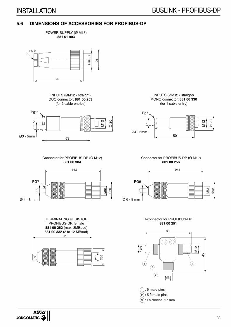
INPUTS (ØM12 - straight)MONO connector: 881 00 330
(for 1 cable entry)
T-connector for PROFIBUS-DP881 00 251
5.6 DIMENSIONS OF ACCESSORIES FOR PROFIBUS-DP
POWER SUPPLY (Ø M18)881 61 903
INPUTS (ØM12 - straight)DUO connector: 881 00 253
(for 2 cable entries)
Connector for PROFIBUS-DP (Ø M12)881 00 256
Connector for PROFIBUS-DP (Ø M12)881 00 304
TERMINATING RESISTORPROFIBUS-DP, female
881 00 262 (max. 3MBaud)881 00 332 (3 to 12 MBaud)
1 : 5 male pins
2 : 5 female pins
3 : Thickness: 17 mm
BUSLINK - PROFIBUS-DP

34
INSTALLATIONBUSLINK - INTERBUS-S
+ 5V
+ 24V
RUN/MOD
ERR/NET
0246
1357
INPUT
IN
OUTOUT
OUT
IN
OUT
IN
(*)
6.1.1 CONNECTION OF THE BUS CABLE TO THE INTERBUS-S CARD OR THE PHOENIX CONTACT BUS TERMINALTwo connecting possibilities:
directly to the Interbus-S card or to the Phoenix Contact bus terminal (*)
Check the pin assignment in the documentation provided with the Interbus-S card or Phoenix Contact bus terminal and observe the corresponding instructions.
Do not forget to set the above mentioned bridges on the corresponding SUB-D connector.
PLC
Island25-pin or 9-pin Sub-
D connector
PLC
Island
9-pin Sub-D
connector
Pin no. Pin no. Pin no. 25-pin 9-pin 9-pin Signal name Buslink / Interbus-S cable SUB-D SUB-D Round (colour)
5 1 1 DO yellow
18 6 2 /DO green
13 5 +5V pins 13 and 25 bridged,
25 9 9 - pins 5 and 9 bridged
9 2 3 DI grey
22 7 4 /DI pink
14 3 5 GND signal (ground) brown
Housing braiding
- - 6 PE green/yellow
- - 7 + 24 V red
- - 8 GND power (0V) blue
Interbus-S cardor Phoenix Contact bus
terminal
JOUCOMATICisland
OU
6 INTERBUS-S
6.1 BUS CONNECTIONThe front panel of the pneumatic spool valve island for Interbus-S is equipped with a 9-pin male panel connector M23 (BUS-IN) and a 9-pin female panel connector M23 (BUS-OUT).The bus cable from the PLC must be connected to the bus input on the fi rst spool valve island. The bus cable from the fi rst to the second spool valve island must be connected as follows:
• from the bus output on the fi rst island • to the bus input on the second island.
Connect the following spool valves islands in the same way (see chapter 1.2).
256 pneumatic spool valve islands can be connected to one Interbus-S branch with a shielded cable with 6 or 9 wires twisted in pairs. Use the 9-wire cable to supply the valve islands with power.

35
INSTALLATION
7
5
2
8
6
1
93
4
OUT2
4
7
1
3
8
96
5
IN
6.1.2 CONNECTION OF THE INTERBUS-S INPUT
View on soldered side of female connector
24V DC power supply: - external (with 6 pin M23 connector) - with the bus cable (see table below)
(*) to connect with cable for internal BUS supply (see chapter 4.3.2).
Female connector to be supplied: Straight 9-pin female connector Thread: M23 (250V~/7,5A) Cable feed-through: 5 - 8 mm Code : 881 61 951 (see accessories/Interbus-S)
6.1.3 CONNECTION OF INTERBUS-S OUTPUT
View on soldered side of male connector
Male connector to be supplied: Straight 9-pin male connector Thread: M23 (250 V~/7,5 A) Cable feed-through: 5 - 8 mm Code : 881 61 952 (see accessories/Interbus-s)
The BUS-OUT connection on the last island in the system must not be made. The bridge (5 - 9) must remain open.It is not necessary to install a terminating resistor. Plug the panel connector on the last island with a protective plug ØM23 (IP 65).
Pin Signal name Buslink Interbus-S cable (colour)
1 DO yellow
2 /DO green
3 DI grey
4 /DI pink
5 GND signal brown
6 PE green/yellow
7 + 24 V (*) red
8 GND power blue
9 - -
Shield terminal - braiding
Pin Signal name Buslink / Interbus-S cable (colour)
1 DO yellow
2 /DO green
3 DI grey
4 /DI pink
5 GND signal brown
6 PE green/yellow
7 + 24 V red
8 GND power blue
9 - -
Shield terminal - braiding
Soldered bridge - Do not forget the soldered bridge between 5 and 9
BUSLINK - INTERBUS-S

36
INSTALLATIONBUSLINK - INTERBUS-S
6.2 PROGRAMMING INSTRUCTIONSFor detailed programming instructions see the PLC and Interbus-S controller manuals.The addresses for the Buslink module are confi gured on the Interbus-S controller. Set the basic address (BA) and the window size with the dip switches. The addresses are not set on the spool valve island.
Automatic addressing: The address assignment is exclusively linked to the spool valve island's position in the bus system
Standard software is available and provided with the Phoenix Contact controller module.
■ PHYSICAL ADDRESSING:
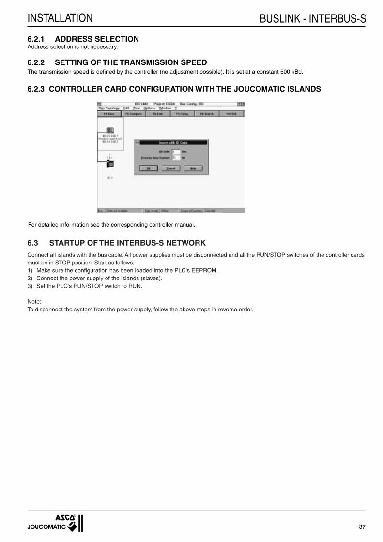
OFFLINE CONFIGURATION (PC not connected to the controller card): Software: IBS CMD.SWT 1 - After startup, the window "SETTING" is displayed: - Select your Interbus-S controller card. - Select "Extended" in the fi eld "scope of function" to access the confi guraton mode. 2 - Select BUS TOPOLOGY in the menu "confi guration". 3 - Select "Insert with identifi cation code . . ."in the menu "edit". 4 - A window "Insert with ID code" is displayed: Enter the following for a JOUCOMATIC island: - ID code : 3. The identifi cation numbers for the connected INTERBUS-S modules are important for the logical addressing (internal number). Each module type has its own identifi cation number (pneumatic, speed variator, analog input/output, etc,). The ID number of the BUSLINK modules is 03. This corresponds to a pneumatic interface addressed with 2 words in logical addressing. - Process data channel: 32 5 - The window "New Device Description" is displayed: - Enter a number for the island in the fi eld "Device number". - Click on "Device Icon . . ." and select the icon for the JOUCOMATIC island in your network (icon no. 5 for example). - Click on "Process Data Addresses" and enter the memory area the PLC allocates to the JOUCOMATIC island you are confi guring (this area can vary according to the PLC used, see the Phoenix-Contact manual).
ONLINE CONFIGURATION (PC connected to the network and islands in operation): 1 - After startup, the window "SETTING" is displayed: - Select "Extended" in the fi eld "scope of function" (confi guration mode). 2 - Click ONLINE 3 - The software displays the network topology (PLC + recognised connected islands) 4 - The JOUCOMATIC island is recognised (C-ad "ID code" and "Process data channel" are displayed) and identifi ed asPhoenix-Contact I module. 5 - Double-click on the right to display the inputs. 6 - Double-click on the left to display the island's characteristics.
37
INSTALLATION
6.2.1 ADDRESS SELECTIONAddress selection is not necessary.
6.2.2 SETTING OF THE TRANSMISSION SPEEDThe transmission speed is defi ned by the controller (no adjustment possible). It is set at a constant 500 kBd.
6.2.3 CONTROLLER CARD CONFIGURATION WITH THE JOUCOMATIC ISLANDS
For detailed information see the corresponding controller manual.
6.3 STARTUP OF THE INTERBUS-S NETWORKConnect all islands with the bus cable. All power supplies must be disconnected and all the RUN/STOP switches of the controller cards must be in STOP position. Start as follows:1) Make sure the confi guration has been loaded into the PLC's EEPROM.2) Connect the power supply of the islands (slaves).3) Set the PLC's RUN/STOP switch to RUN.
Note:To disconnect the system from the power supply, follow the above steps in reverse order.
BUSLINK - INTERBUS-S

38
INSTALLATIONBUSLINK - INTERBUS-S
6.4 DIAGNOSTICS
6.4.1 LED INDICATIONS■ ON THE BUSLINK MODULE:The Buslink module is provided with 4 diagnostic LEDs.• ERR/NET (red) lights up as soon as data exchange from the bus is interrupted.• RUN/MOD (green) is constantly illuminated during regular operation as soon as signals can be received from the bus.• + 24V (green) is constantly illuminated as soon as the 24V power supply to the valves is connected.• + 5V (green) is constantly illuminated as soon as the 24V power supply for the bus electronics (and to the sensor inputs) is connected.
■ ON THE INTERBUS-S CONTROLLER:Several indicators on the front panel of the controller allow to locate errors in the INTERBUS-S system, sensors / relays, valves, LEDs etc. An error can be deleted with the RUN/STOP button on the controller. See also the INTERBUS-S controller manual.
Module error:The power supply for the spool valve coils is monitored on the BUSLINK module. An error is signalised as soon as the voltage drops below 18 Volts. This error is indicated together with the segment number on the front panel of the controller. A module error does not cause the system to be stopped. The module error must be processed by the software. Take the option 13 or 25 to inhibit the 24 VDC detection (see chapter 2.4.1)
6.4.2 DIAGNOSTICS REGISTERThe diagnostics register gives the error status of the INTERBUS-S system in bit information. An appropriate software evaluation and/or error reaction is possible by bit comparison.
The following information is stored:• Module error (voltage loss for the spool valve supply)• Bus error (Remote Bus Error)• Controller error• Number of the bus segment at fault
For further information see the manual for the INTERBUS-S controller.
6.4.3 RESET POSITIONINTERBUS-S islands are provided with a reset into zero position.
6.4.4 FUSESSee chapter 4.8.

39
INSTALLATION
M12
Ø 2
0
50
Pg7
Ø4 - 6mm
53
M12
Ø 2
0
Pg11
Ø3 - 5mm
51
Ø26PG 9
ØM
23
51
Ø26PG 9
ØM
23
6.5 ACCESSORIES FOR INTERBUS-S
+
Pneumatic blanking plate for unused spool valve place
Electrical and pneumatic blanking plates for unused pilot valve place
Straight 6-pin female connector M23 for 24 V DC power supply
Straight 5-pin male duo connector M12 for 2 inputs Ø3 - 5 mm
Straight 5-pin male mono connector M12 (1 cable) for inputs
9-pin female connector M23 for Interbus-S input (BUS-IN)
9-pin male connector M23 for Interbus-S output (BUS-OUT)
881 00 358 881 00 357
881 00 356
881 61 960
881 00 253
881 00 330
881 61 951
881 61 952
Description CodesSpool valves
ISO 02ISO 01
6.6 DIMENSIONS OF ACCESSORIES FOR INTERBUS-S
POWER SUPPLY (Ø M23)881 61 960
INPUTS (ØM12 - straight)MONO connector: 881 00 330
(for 1 cable entry)
INPUTS (ØM12 - straight)DUO connector: 881 00 253
(for 2 cable entries)
FEMALE CONNECTOR - INTERBUS-S INPUT881 61 951
MALE CONNECTOR - INTERBUS-S OUTPUT881 61 952
61
Ø26
PG 13,5
ØM
23
BUSLINK - INTERBUS-S

40
INSTALLATIONBUSLINK - DEVICE NET
4
5 1
3
2
����44
K K
E
G H
L1
F
L2
+ 5V
+ 24V
RUN/MOD
ERR/NET
0246
1357
INPUT
Pg21
3
1
5
INPUT
1357
0246
0OUTPUT
1357
0246
3+5V
+24VRUN/MODERR/NET
3
5
1
H2
H1
ISO 02 ISO 01
H1 14 14
H2 43 28
7 DEVICE NET
7.1 BUS CONNECTIONThe front panel of the pneumatic spool valve island for DEVICE NET is equipped with a 5-pin male panel connector 7/8 - 16 UN (E).
The bus can be connected in the two following ways:
• directly to the island with the T-connector.• with a straight connector, cable (max. length: 3 m) and the Device Net distributor box.
The modules on either side of the system must be provided with terminating resistors (L1 or L2).
7.1.1 DIRECT CONNECTION WITH T-CONNECTOR
View on screw side Device Net connector
24V DC power supply: - either from an external source - or by the bus cable (see table below)
The following accessories are required for wiring:
■ 5-pin male/female/female T-connector 7/8 - 16 UN (F), code: 881 61 932.
■ 5-pin female connector 7/8 - 16 UN for Device Net input (G), code: 881 61 930.
■ 5-pin male connector 7/8 - 16 UN for Device Net output (H), code: 881 61 931.
■ Male terminating resistor for Device Net (L1), code: 881 61 934.NOTE : If the user connects the bus in the opposite way as described above, i.e. input over 5-pin male connector (H),a female terminating resistor (L2) must be used, code: 881 61 933.
■ Shielded cable for Device Net (K) 2 wires x 1,53 mm2 + 2 wires x 0,95 mm2, (cable to be ordered separately).
Connection of connectors 7/8 - 16 UN (G and H)
For installation purposes the T-connector for the bus and the 2 connectors are placed at a slant angle (see diagram below).
Pin Signal name Description Device-Net cable
(colours)
1 DRAIN shield, capacitive ground (shield)
2 +24V-CAN power supply by the bus red
3 GND-CAN ground black
4 CAN-H data - high active white
5 CAN-L data - low active blue
Island

41
INSTALLATION
��3m max.
44
4
K K
E
G
7.1.2 CONNECTION WITH STRAIGHT 5-PIN FEMALE CONNECTOR
The following accessories are required for wiring:
■ 5-pin female connector 7/8 - 16 UN (G), code: 881 61 930.
■ Shielded cable for Device Net (K) 2 wires x 1,53 mm2 + 2 wires x 0,95 mm2, (cable to be ordered separately).
Connection of the connector 7/8 - 16 UN (G)Identical to chapter 7.1.1 (see previous page).
Island
Device Net distributor box
BUSLINK - DEVICE NET

42
INSTALLATIONBUSLINK - DEVICE NET
125 kBd
250 kBd
500 kBd
-
+ 5 V
+ 24 V
RUN/MOD
ERR/NET
ON
81
41
ON
+ 5 V
+ 24 V
RUN/MOD
ERR/NET
ON
81
41
ON
ON
8 7 6 5 4 3 2 1
1 2 4 8 16 32 - -
ADR 03
ADR 04
. . .
ADR 10 . . .
ADR 63
0 0 1 0 0 0 - -
0 1 0 1 0 0 - -
1 1 1 1 1 1 - -
Position 8 7 6 5 4 3 2 1
1 1 0 0 0 0 - -
ON
4 3 2 1
4 3 2 1
0 0 - -
1 0 - -
- - - -
0
1
2
3
0 1 - -
Position
7.2.1 ADDRESS SELECTION
Example for spool valve with address # 03
NOTE: The default address of the module is "03" at delivery.You can change the island's address with the dip switches in the bus coupling module.Only addresses greater than "03" are allowed for the pneumatic spool valve islands.
7.2.2 SETTING OF THE TRANSMISSION SPEED
NOTE: The transmission speed is set at 500 kBd at delivery (dip switch in the position shown above).
Signifi cative value
Transmissionspeed decimal
7.2 PROGRAMMING INSTRUCTIONSConfi gure the controller card (DEVICE NET network card) with the "Device Net Manager" software.
To include pneumatic spool valve islands (slaves) in the confi guration, you must change the scanner's scanlist. For detailed information on the scanner and the software tool "DeviceNet Manager" see the corresponding manuals.

43
INSTALLATION
Click the "Save to SDN..." button to save the modifi cations in the scanner's scanlist.
7.2.3 CONFIGURATION OF THE CONTROLLER CARD WITH THE JOUCOMATIC ISLANDSTo change the scanlist, open the „scanlist setup“ window (see below) in the "DeviceNet Manager" and choose the default values as indicated below:
Position of the two codes (≡ 4 Byte ≡ 32 Bits) in the block transfer table.
7.3 STARTUP OF THE DEVICE NET NETWORKConnect all islands with the bus cable. All power supplies must be disconnected and all the RUN/STOP switches of the controller cards must be in STOP position. Start as follows:1) Make sure the confi guration has been loaded into the PLC's EEPROM.2) Connect the power supply of the islands (slaves).3) Set the PLC's RUN/STOP switch to RUN.
Note:To disconnect the system from the power supply, follow the above steps in reverse order.
OFFLINE CONFIGURATION (PC not connected to the controller card) Software: DEVICE-NET manager 1 - To integrate a JOUCOMATIC island in the network click on "ADD Device" and confi rm the "asco:joucomatic" Buslink by clic-king OK. 2 - Click on "ADD Device from" and select "Proj" The island is displayed in the "Scan list" window 3 - Double-click on the island and enter the following: - I/O type : Polled - I/O setup : Poll Rx Size : 4 bytes Poll Tx Size : 4 bytes
ONLINE CONFIGURATION (PC connected to the networks and islands in operation) All data is initialised automatically in case of an ONLINE confi guration connected to the controller card.
To obtain the following window, click on "Edit scan List" in "Module and Channel Confi guration".
To modify the parameters click the "Edit I/O Parameters" button.
BUSLINK - DEVICE NET

44
INSTALLATIONBUSLINK - DEVICE NETConfi gure the window as indicated below and confi rm by clicking OK.
Come back to the "Scan list Editor" window, click on "Auto Map" and enter the "Input Block Xfer" and "Output Block Xfer" parameters as indicated below. The 2 "Start Word" parameters must correspond to those parametered in the Datatable Map window.
Connect all islands with the bus cable. All power supplies must be disconnected and all the RUN/STOP switches of the controller cards must be in STOP position. Start as follows:1) Make sure the confi guration has been loaded into the PLC's EEPROM.2) Connect the power supply of the islands (slaves).3) Set the PLC's RUN/STOP switch to RUN.
Note:To disconnect the system from the power supply, follow the above steps in reverse order.

45
INSTALLATION
7.4 DIAGNOSTICS
7.4.1 LED INDICATIONSON THE BUSLINK MODULE:
The buslink module is provided with 4 diagnostic LEDs.
• ERR/NET green fl ashing the controller is ONLINE, but has no connection to the master. green connection to the master has been established. red no communication possible. This means, e.g. that two different islands have been provided with the same island number.
• RUN/MOD green fl ashing the island was disconnected during operation (idle). green regular operation. red fl ashing recoverable error, overvoltage, undervoltage, power supply to the spool valves/outputs is interrupted. red irrecoverable error, internal error.
• +24V (green) lights up as soon as the power supply for the spool valves/outputs is connected.
• +5V (green) lights up as soon as the power supply for the bus electronics/inputs is connected.
7.4.2 DIAGNOSTICS REGISTERThe diagnostics register gives the error status of the Device Net system in bit information. An appropriate software evaluation and/or error reaction is possible by bit comparison.
7.4.2 RESET POSITIONDEVICE NET islands are provided with a reset into zero position.
7.4.3 FUSESSee chapter 4.8.
BUSLINK - DEVICE NET

46
INSTALLATIONBUSLINK - DEVICE NET
7.5 ACCESSORIES FOR DEVICE-NET (for dimensions see following page)
+
(K) Cable to be supplied separately
Pneumatic blanking plate for unused spool valve place
Electrical and pneumatic blanking plates for unused pilot valve place
Straight 4-pin female connector M18 for 24 V DC power supply
Straight 5-pin male duo connector M12for 2 inputs Ø3 - 5 mm
Straight 5-pin male mono connector M12 (1 cable) for inputs
G Straight 5-pin female connector 7/8-16 UN for DEVICE NET
H Straight 5-pin male connector 7/8-16 UN for DEVICE NET
F
5-pin male / female / female T-connector 7/8-16 UN for DEVICE NET
L1 120 ohms male terminating resistor for DEVICE NET
L2 120 ohms female terminating resistor for DEVICE NET
3 1/2" fl oppy disk for the confi guration of the PLC controller card intended for Buslink Device-Net islands
881 00 358 881 00 357
881 00 356
881 61 903
881 00 253
881 00 330
881 61 930
881 61 931
881 61 932
881 61 934
881 61 933
881 66 909
Description CodesSpool valves
ISO 02ISO 01
�����
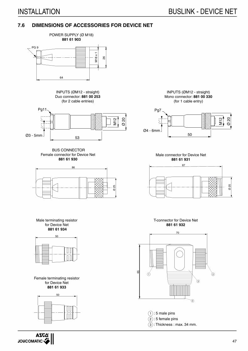
47
INSTALLATION
53
M12
Ø 2
0
Pg11
Ø3 - 5mm
����
86
Ø 2
5 ����87
Ø 2
5
65
70
1 2
2
3
26
M18
x 1
64
PG 9
50
50
M12
Ø 2
0
50
Pg7
Ø4 - 6mm
7.6 DIMENSIONS OF ACCESSORIES FOR DEVICE NET
BUS CONNECTORFemale connector for Device Net
881 61 930Male connector for Device Net
881 61 931
Male terminating resistorfor Device Net 881 61 934
T-connector for Device Net881 61 932
POWER SUPPLY (Ø M18)881 61 903
INPUTS (ØM12 - straight)Duo connector: 881 00 253
(for 2 cable entries)
Female terminating resistorfor Device Net
881 61 933
INPUTS (ØM12 - straight)Mono connector: 881 00 330
(for 1 cable entry)
1 : 5 male pins
2 : 5 female pins
3 : Thickness : max. 34 mm.
BUSLINK - DEVICE NET

48
INSTALLATIONBUSLINK - FIPIO
0246
1357
INPUT
Pg21
+ 5V
+ 24V
RUN
COM
I/OERR
1
2
4
3
5
G
E
K
4
H
K
2 2
ACC4
30
4
24
1 3
2 2
4
ACC4
8 FIPIO NETWORK
8.1 CONNECTION OF THE FIPIO BUSThe front panel of the pneumatic spool valve island for FIPIO is equipped with a 5-pin male panel connector ØM12 (E).
The bus can be connected in the two following ways:
• with a TSX FP ACC4 connector housing;• with a T-connector directly plugged into the M12 outlet on the island.
View from screw side of 5-pin female connector
Pins Signal name Description
1 + FIPIO network
2 not connected /
3 - FIPIO network
4 not connected /
5 not connected /
Housing shield
Island
The following accessories are required for wiring:
■ Straight 5-pin female connector M12 for FIPIO (G), (cable dia. 6 to 8 mm), code: 881 00 256.
■ Main cable for FIPIO (K), shielded twisted pair (cable to be ordered separately).
■ Stub cable for (H), 2 shielded twisted pairs (cable to be ordered separately).
The terminating resistors must be ordered separately.
Connection of the stub cable (H) to the straight connector (G)
• Strip the cable as shown in opposite diagram.
• Open the connector.
• Feed the cable into the cable gland.
• Connect the wires to the terminals (see below) and fi x the cable onto the shield with the metal clamp.
Connection to the straight M12 connector (G)
Stub cable (H)(double pair)
Straight 5-pin female con-nector M12 (G)
Main cable (K)(simple pair)
8.1.1 CONNECTION WITH CONNECTOR HOUSING (type TSX FP ACC4)With an ACC4 connector housing the max. number of islands on each segment is 32.NOTE - The TSX FP ACC4 connector housing must be ordered separately.

49
INSTALLATION
3024
4
3
1
5
INPUT
1357
0246
0OUTPUT
1357
0246
3+5V
+24VRUN/MODERR/NET
3
5
1
H1
H2
E
KK
2 2
F JJ
L
ISO 02 ISO 01
H1 4 4
H2 38 23
1
2
4
3
5
The following accessories are required for wiring:
■ 5-pin female/female/female T-connector M12 for FIPIO (F), code: 881 00 252.
■ Straight, 5-pin male connector M12 (J), code: 881 00 279 (provide for 2 for each island).
■ Male Terminating resistors for FIPIO network equipped with T-connectors (L), code: 881 00 333.
■ Shielded cable for FIPIO (K), twisted in pairs (to be ordered separately).
Cable connection • Strip the cable as shown in the diagram below. • Open the connector. • Feed the cable into the cable gland. • Connect the wires to the terminals and fi x the cable onto the shield with the metal clamp.
8.1.2 DIRECT CONNECTION WITH T-CONNECTOR
For installation purposes the T-connector for the bus and the 2 connectors are placed at a slant angle (see diagram below).
Connection of the straight M12 connectors (J)
View on screw side of 5-pin male connector
With a T-connection the max. number of islands on each segment is 24.
Island
BUSLINK - FIPIO
Pins Signal name Description
1 + FIPIO network
2 not connected /
3 - FIPIO network
4 not connected /
5 not connected /
Housing shield

50
INSTALLATIONBUSLINK - FIPIO
+ 5 V
+ 24 V
RUN
COM
ON
OF
F
81
ERR
I/O
ON
OFF
1 2 3 4 5 6 7 8
8.2.1 ADDRESS SELECTIONIn the FiPIO network the address 00 is reserved for the PLC (TSX model 40 or APRIL 5000) which is the bus manager.Address no. 63 is reserved for the programming terminal.
Select the address number for the pneumatic spool valve island as follows:
Example of an island with address # 03
NOTE:The default address of the module is "03" at deliveryYou can change the island's address with the dip switches in the bus coupling module.Only addresses greater than "01" are allowed for the pneumatic spool valve islands.
8.2 PROGRAMMING INSTRUCTIONSINTEGRATION UNDER XTELLimitations:The confi guration, programming and diagnostics of the BUSLINK on a FIPIO network with the XTEL-CONF tool is possible under the following conditions:· with XTEL V52 if the catalog diskette TXT R CTG V52 is installed;· with XTEL V6 (and PL7-3 V6).The island can only be put into operation from version V5.3 of the processor series 7, TSX model 40.
INTEGRATION UNDER ORPHEELimitations:- The confi guration editor of ORPHEE allows to connect and confi gure components on the FIPIO bus. - ORPHEE versions ≥V6.2 are required for confi guration.
The operating mode to be able to use the island on a FIPIO bus controlled by APRIL 5000 is described in the following paragraphs.For detailed information on the connecting principles and confi guration of the components on the FIPIO bus, see the documentation "Additive ORPHEE/ORPHEE-DIAG for using the FIPIO bus on APRIL 5000" no. TEM10000/10800F.The island can only be put into operation with a CPU5030 or CPU5130 version 2.
8.2.2 SETTING OF THE TRANSMISSION SPEEDThe transmission speed does not need to be adjusted, it is fi xed at 1 MBaud.
Signifi cative value 1 2 4 8 16 32 64 -
Address 00
ADR 01
ADR 02
ADR 03
. . .
ADR 62
ADR 63
0 1 0 0 0 0 0 -
1 1 0 0 0 0 0 -
Position 1 2 3 4 5 6 7 8
reserved
1 0 0 0 0 0 0 -
0 1 1 1 1 1 0 -
-reserved
-

51
INSTALLATION
8.2.3 CONFIGURATION OF THE CONTROLLER CARD WITH THE JOUCOMATIC ISLANDSINTEGRATION UNDER XTEL:To confi gure the FIPIO network see the documentation TXT DM FSDP V6F provided byTELEMECANIQUE.The confi guration, programming and diagnostics of an island on a FIPIO network with the XTEL-CONF tool is possible under the following conditions:· with XTEL V52 if the catalog diskette TXT R CTG V52 is installed;· with XTEL V6 (and PL7-3 V6).The island can only be put into operation from version V5.3 of the processor series 7, TSX model 40.
Selecting the BUSLINK:Click on Conf in the window Station Tool to display the Station Tool-conf. window.Select Confi g. distant I/O in the menu Defi nition to display the Confi guration of remote devices window in which you can choose the connections.
Select the fi eld corresponding to the Buslink island address you are confi guring and press RETURN. A window to defi ne the profi le is displayed. Select STD-P (= standard profi le).
The following window is displayed:
BUSLINK islands correspond to the profi le family FSD-C8. Select FSD C8 and confi rm you choice by pressing RETURN.
If you click on "Parameters", you can confi gure the data generated by the PLC. For further details on this mode of operation see the corresponding manual.
Confi rm you confi guration by clicking OK. The Confi guration of remote devices window is displayed once again with FSD-C8 next to the confi gured address number.As soon as the confi guraton of the spool valve island is fi nished you can change the address number of the next BUSLINK and confi gure it.
BUSLINK - FIPIO
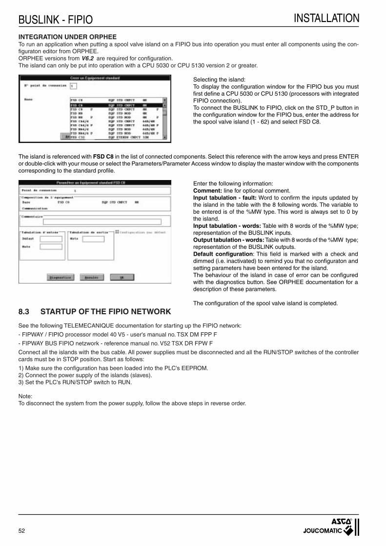
52
INSTALLATIONBUSLINK - FIPIO
8.3 STARTUP OF THE FIPIO NETWORK
See the following TELEMECANIQUE documentation for starting up the FIPIO network:
- FIPWAY / FIPIO processor model 40 V5 - user's manual no. TSX DM FPP F
- FIPWAY BUS FIPIO netzwork - reference manual no. V52 TSX DR FPW F
Connect all the islands with the bus cable. All power supplies must be disconnected and all the RUN/STOP switches of the controller cards must be in STOP position. Start as follows:
1) Make sure the confi guration has been loaded into the PLC's EEPROM.2) Connect the power supply of the islands (slaves).3) Set the PLC's RUN/STOP switch to RUN.
Note:To disconnect the system from the power supply, follow the above steps in reverse order.
INTEGRATION UNDER ORPHEETo run an application when putting a spool valve island on a FIPIO bus into operation you must enter all components using the con-fi guraton editor from ORPHEE.ORPHEE versions from V6.2 are required for confi guration.The island can only be put into operation with a CPU 5030 or CPU 5130 version 2 or greater.
Selecting the island:To display the confi guration window for the FIPIO bus you must fi rst defi ne a CPU 5030 or CPU 5130 (processors with integrated FIPIO connection).To connect the BUSLINK to FIPIO, click on the STD_P button in the confi guration window for the FIPIO bus, enter the address for the spool valve island (1 - 62) and select FSD C8.
The island is referenced with FSD C8 in the list of connected components. Select this reference with the arrow keys and press ENTER or double-click with your mouse or select the Parameters/Parameter Access window to display the master window with the components corresponding to the standard profi le.
Enter the following information:Comment: line for optional comment.Input tabulation - fault: Word to confi rm the inputs updated by the island in the table with the 8 following words. The variable to be entered is of the %MW type. This word is always set to 0 by the island.Input tabulation - words: Table with 8 words of the %MW type; representation of the BUSLINK inputs.Output tabulation - words: Table with 8 words of the %MW type; representation of the BUSLINK outputs.Default confi guration: This fi eld is marked with a check and dimmed (i.e. inactivated) to remind you that no confi guraton and setting parameters have been entered for the island.The behaviour of the island in case of error can be confi gured with the diagnostics button. See ORPHEE documentation for a description of these parameters.
The confi guration of the spool valve island is completed.

53
INSTALLATION
+ 5 V
+ 24 V
RUN
COM ERR
I/O
8.4.3 RESET POSITIONFIPIO islands are provided with a reset into zero position (confi guration bridge on two pins)
Bridge to confi gure the reset position
To obtain a self-locking reset position remove the bridge and put it on one pin only so as not to lose it.
8.4.4 FUSESSee chapter4.8.
If such an error occurs, the red I/O LED lights up (see above)
- ON THE BUS CONTROLLER OF THE PLCThe front panel of the controller is equipped with several displays which allow to locate errors in the FIPIO system and sensors/actu-ators. For detailed information see the FIPIO controller manual.
8.4.2 DIAGNOSTICS REGISTERThe diagnostics register gives the error status of the FIPIO system in bit information. An appropriate software evaluation and/or error reaction is possible by bit comparison.
8.4 DIAGNOSTICS
8.4.1 LED INDICATIONS- ON THE BUSLINK MODULEThe buslink module is provided with 6 diagnostic LEDs to FIPIO standard.• RUN / green: All components connected to power supply - No display if not connected to power supply - Flashing light if bus communication is interrupted because another component accesses the same address (fre-
quency = approx. 2Hz).• COM / yellow : Communication is activated. - No display when there is no data exchange over the FIPIO bus or when communication is interrupted. - Flashing light during autotest, initialisation and connection of new components (Frequency = approx. 2 Hz). - Flashing light when the components participate in the data exchange over the FIPIO bus; fl ashing is at a fi xed
frequency of approx. 2 MHz.• ERR / red: Major error - No display during regular operation. - Flashing light during autotest, initialisation and connection of new components and as long as the components are
not logically connected to the FIPIO network (frequency = approx. 2 Hz). - Lights up in case of error requiring an exchange of component or module (fault in a subassembly, assembly of
incompatible modules etc.)• I/O / red : Minor error - No display during regular operation. - Flashing light during autotest, initialisation and connection of new components (frequency = approx. 2Hz). - Lights up in case of error not caused by one of the components.As soon as the components are powered-on, these 4 LEDS fl ash simultaneously during the components' autotest phase. If the LEDS continue to fl ash after the autotest, this means that the address which was confi gured is already occupied.• + 24V (green) lights up as soon as the power supply for the spool valves/outputs is connected.• +5V (green) lights up as soon as the power supply to the bus electronics/inputs is connected.
ERRORSErrors in series 7 are displayed in the word STATUS A and in the APRIL 5000 under "external Error".
STATUS A External error Signifi cation
Bit 3 Bit 1 Problem with 24V power supply to the outputs
Bit 1 Bit 3 Problem with power supply to the bus interface
Bit 0 Bit 4 Problem of overload at the outputs
BUSLINK - FIPIO

54
INSTALLATIONBUSLINK - FIPIO
Pneumatic blanking plate for unused spool valve place
Electrical and pneumatic blanking plates for unused pilot valve place
Straight 4-pin female connector M18 for 24 V DC power supply
Straight 5-pin male duo connector M12for 2 inputs Ø3 - 5 mm
Straight 5-pin male mono connector M12 (1 cable) for inputs
F
5-pin female / female / female T-connector M12 for FIPIO
G Straight 5-pin female connector M12 for FIPIO
J Straight 5-pin male connector M12 for cable dia. 6 - 8 mm
L
Terminating resistor for FIPIO for a T-connector, male M12 plug
881 00 358 881 00 357
881 00 356
881 61 903
881 00 253
881 00 330
881 00 252
881 00 256
881 00 279
881 00 333
Description CodesSpool valves
ISO 02ISO 01
+
8.5 FIPIO ACCESSORIES (for dimensions see following page)
(K) (H) Cable to be supplied separately

55
INSTALLATION
53
M12
Ø 2
0
Pg11
Ø3 - 5mm
26
M18
x 1
64
PG 9
87,3
M12 25
M12
Ø19
38
63
M12
11
2
1
M12
Ø 2
0
50
Pg7
Ø4 - 6mm
56,5
Ø20
M12
Ø 6 - 8 mm
62
Ø20
M12
Ø 6-8 mm
PG9
67
Ø20
M12
PG9
8.6 DIMENSIONS OF ACCESSORIES FOR FIPIO
POWER SUPPLY (Ø M18)881 61 903
INPUTS (ØM12 - straight)DUO connector: 881 00 253
(for 2 cable entries)
Female connector for FIPIO (Ø M12)881 00 256
INPUTS (ØM12 - straight)MONO connector: 881 00 330
(for 1 cable entry)
T-CONNECTOR FOR FIPIO881 00 252
Male connector for FIPIO (ØM12)881 00 279
1 5 female pins
2 Thickness: max. 25 mm
MALE TERMINATING RESISTOR FOR FIPIO881 00 333
BUSLINK - FIPIO
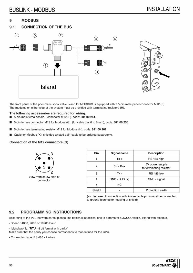
56
INSTALLATIONBUSLINK - MODBUS
2 2
GG K
H
F
E
K
+ 5V
+ 24V
RUN/MOD
ERR/NET
0246
1357
INPUT
4
51
3
2
9 MODBUS
9.1 CONNECTION OF THE BUS
The front panel of the pneumatic spool valve island for MODBUS is equipped with a 5-pin male panel connector M12 (E).The modules on either side of the system must be provided with terminating resistors (H).
The following accessories are required for wiring:■ 5-pin male/female/male T-connector M12 (F), code: 881 00 251.
■ 5-pin female connector M12 for Modbus (G), (for cable dia. 6 to 8 mm), code: 881 00 256.
■ 5-pin female terminating resistor M12 for Modbus (H), code: 881 00 262.
■ Cable for Modbus (K), shielded twisted pair (cable to be ordered separately).
Connection of the M12 connectors (G)
Pin Signal name Description
1 Tx + RS 485 high
2 5V - Bus
5V power supply to terminating resistor
3 Tx - RS 485 low
4 GND - BUS (*) GND - signal
5 NC -
Shield - Protection earth
View from screw side of connector
(*) In case of connection with 2-wire cable pin 4 must be connected to ground (connector housing or shield).
9.2 PROGRAMMING INSTRUCTIONSAccording to the PLC network cards, please fi nd below all specifi cations to parameter a JOUCOMATIC island with Modbus.
- Speed : 4800, 9600 or 19200 Baud
- Island profi le: "RTU - 8 bit format with parity"Make sure that the parity you choose corresponds to that defi ned for the CPU.
- Connection type: RS 485 - 2 wires
Island

57
INSTALLATION
+ 5 V
+ 24 V
RUN/MOD
ERR/NET
ON
81
41
ON
+ 5 V
+ 24 V
RUN/MOD
ERR/NET
ON
81
41
ON
OFF
ON
8 7 6 5 4 3 2 1
1 2 4 8 16 32 64 128
0 0 1 0 0 0 0 0
1 1 1 1 1 1 1 1
Position 8 7 6 5 4 3 2 1
0 0 0 0 0 0 0 0
0 1 0 0 0 0 0 0
1 1 0 0 0 0 0 0
OFF
ON
4 3 2 1
0 1 1 1 1 1 1 1
Signifi cative value
Address 00
ADR 02
ADR 03
ADR 04
I
I
ADR 254
ADR 255
9.2.1 ADDRESS SELECTION
Example of an island with address # 03
NOTE:The default address of the module is "03" at deliveryYou can change the island's address with the dip switches in the bus coupling module.
9.2.2 SETTING OF THE TRANSMISSION SPEED AND THE PARITY
NOTE: the transmission speed is factory set at 19200 Bd and the parity is factory set at "even".
4800 Bd
9600 Bd
19200 Bd
4 3 2 1
0 0
1 0
Transmissionspeed
0 1
Position
1 1
1 0
0 x
Parity
none
even
odd
x : neutral (0 or 1)
BUSLINK - MODBUS

58
INSTALLATIONBUSLINK - MODBUS
V3.7 . . . . . . . . . . . V2.0 V1.7 . . . . . . . . . . V0.0
9.2.3 CONFIGURATION OF THE CONTROLLER CARD WITH THE JOUCOMATIC ISLANDS
To enable data exchange between the JOUCOMATIC island and the PLC, you must parameter the rasters as follows:
- Use the write function to assign the outputs (spool valves + additional outputs) (function code 10H)
- Use the read function to read the inputs (additional inputs) (function code 03H or 04H)
- The number of words used in both cases is 2.
- The island is divided up as follows:
Outputs Register 0 : Spool valves/outputs V0.0 to V1.7
Register 1 : Spool valves/outputs V2.0 to V3.7
Inputs Register 2 : Inputs I0.0 t I1.7
Register 3 : Inputs I2.0 to I3.7
Example: Output register (2 words)
Basic register 0
For example, in order to read the inputs, enter in the raster
- the island's address
- the read function (03H or 04H)
- register 2 (basic register)
- the number of words = 2 (you then read register 2 and register 3, i.e. 2 words).
This results in the following table:
YY : PLC register number allocated to the spool valves/island outputsXX : PLC register number allocated to the island inputs
9.3 STARTUP OF THE MODBUS NETWORKConnect all the islands with the bus cable. All power supplies must be disconnected and all the RUN/STOP switches of the controller cards must be in STOP position. Start as follows.
1) Make sure the PLC's confi guration is correct.
2) Connect the power supply of the islands (slaves).
3) Set the PLC's RUN/STOP switch to RUN.
To disconnect the system from the power supply follow the above steps in reverse order.
Code function
03H/04H 10H
Number of words 2 2
Read address Register = 2 YY
Write address XX Register =0
Inputs Outputs
59
INSTALLATION
9.4 DIAGNOSTICS
9.4.1 LED INDICATIONS■ ON THE BUSLINK MODULE:
The buslink module is provided with 4 diagnostic LEDs (see 2.2).• ERR/NET (green) Flashing light signals that the module is connected.• RUN/MOD (green) Regular operation.• + 24V (green) is constantly illuminated as soon as the power supply to the spool valves is connected.• + 5V (green) is constantly illuminated as soon as the power supply for the electronics and the inputs is connected.
9.4.2 DIAGNOSTICS REGISTER
Module error:
The power supply for the spool valve coils is monitored on the BUSLINK module. An error is signalised as soon as the voltage drops below 20 Volts. A module error does not cause the system to be stopped. The module error must be processed by the software.
For detailed information see the MODBUS manual.
9.4.3 RESET POSITION If MODBUS islands are disconnected from the network they maintain their status, i.e. the coils remain in their last position (reset position is maintained).
- A reset into zero position is available upon request (i.e. all coils are reset to zero).
9.4.4 FUSES See chapter 4.8.
BUSLINK - MODBUS

60
INSTALLATIONBUSLINK - MODBUS
9.5 ACCESSORIES FOR MODBUS (for dimensions see following page)
Pneumatic blanking plate for unused spool valve place
Electrical and pneumatic blanking plates for unused pilot valve place
Straight 4-pin female connector M18 for 24 V DC power supply
Straight 5-pin male duo connector M12 for 2 inputs Ø3 - 5 mm
Straight 5-pin male mono connector M12 (1 cable) for inputs
F
5-pin male / female / male T-connector for Modbus
G Straight 5-pin female connector M12 for Modbus for cable dia. 6 - 8 mm
H Female plug - terminating resistor for Modbus
881 00 358 881 00 357
881 00 356
881 61 903
881 00 253
881 00 330
881 00 251
881 00 256
881 00 262
Description Codes
(K) Cable to be supplied separately
Spool valves
ISO 02ISO 01
+

61
INSTALLATION
26
M18
x 1
64
PG 9
53
M12
Ø 2
0Pg11
Ø3 - 5mm
45
M12
M12
60
M12
11
2
3
61
Ø20
M12
M12
Ø 2
0
50
Pg7
Ø4 - 6mm
56,5
Ø20
M12
Ø 6 - 8 mm
PG9
INPUTS (ØM12 - straight)MONO connector: 881 00 330
(for 1 cable entry)
T-connector for MODBUS (ØM12)881 00 251
9.6 DIMENSIONS OF ACCESSORIES FOR MODBUS
POWER SUPPLY (Ø M18)881 61 903
INPUTS (ØM12 - straight)DUO connector: 881 00 253
(for 2 cable entries)
CONNECTOR FOR MODBUS (Ø M12)881 00 256
Female terminating resistor for MODBUS, 881 00 262
1 : 5 male pins
2 : 5 female pins
3 : Thickness: 17 mm
BUSLINK - MODBUS
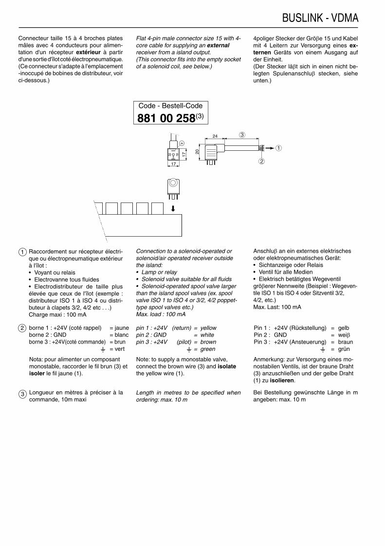
17
12 17
20
24
3
3
1
2
BUSLINK - VDMA
1
2
3
Connecteur taille 15 à 4 broches plates mâles avec 4 conducteurs pour alimen-tation d'un récepteur extérieur à partir d'une sortie d'îlot coté électropneumatique. (Ce connecteur s'adapte à l'emplacement -inoccupé de bobines de distributeur, voir ci-dessous.)
borne 1 : +24V (coté rappel) = jauneborne 2 : GND = blanc borne 3 : +24V(coté commande) = brun = vert
Raccordement sur récepteur électri-que ou électropneumatique extérieur à l'îlot :• Voyant ou relais• Electrovanne tous fl uides• Electrodistributeur de taille plus élevée que ceux de l'îlot (exemple : distributeur ISO 1 à ISO 4 ou distri-buteur à clapets 3/2, 4/2 etc . . .)Charge maxi : 100 mA
Flat 4-pin male connector size 15 with 4-core cable for supplying an externalreceiver from a island output.(This connector fi ts into the empty socket of a solenoid coil, see below.)
Connection to a solenoid-operated or solenoid/air operated receiver outside the island:• Lamp or relay• Solenoid valve suitable for all fl uids• Solenoid-operated spool valve larger than the island spool valves (ex. spool valve ISO 1 to ISO 4 or 3/2, 4/2 poppet-type spool valves etc.)Max. load : 100 mA
4poliger Stecker der Gröβe 15 und Kabel mit 4 Leitern zur Versorgung eines ex-ternen Geräts von einem Ausgang auf der Einheit.(Der Stecker läβt sich in einen nicht be-legten Spulenanschluβ stecken, siehe unten.)
Anschluβ an ein externes elektrisches oder elektropneumatisches Gerät:• Sichtanzeige oder Relais• Ventil für alle Medien• Elektrisch betätigtes Wegeventil gröβerer Nennweite (Beispiel : Wegeven-tile ISO 1 bis ISO 4 oder Sitzventil 3/2, 4/2, etc.)Max. Last: 100 mA
Code - Bestell-Code
881 00 258(3)
Longueur en mètres à préciser à la commande, 10m maxi
Length in metres to be specifi ed when ordering: max. 10 m
Bei Bestellung gewünschte Länge in m angeben: max. 10 m
pin 1 : +24V (return) = yellowpin 2 : GND = whitepin 3 : +24V (pilot) = brown = green
Pin 1 : +24V (Rückstellung) = gelbPin 2 : GND = weiβPin 3 : +24V (Ansteuerung) = braun = grün
Nota: pour alimenter un composant monostable, raccorder le fi l brun (3) et isoler le fi l jaune (1).
Note: to supply a monostable valve, connect the brown wire (3) and isolate the yellow wire (1).
Anmerkung: zur Versorgung eines mo-nostabilen Ventils, ist der braune Draht (3) anzuschließen und der gelbe Draht (1) zu isolieren.