Pneumatic Shut-off Valves - maxoncorp.com · general purpose or corrosive gases; oxygen...
54
MAXON Series 8000 Pneumatic Shut-off Valves Technical Catalog
-
Upload
vuongnguyet -
Category
Documents
-
view
226 -
download
0
Transcript of Pneumatic Shut-off Valves - maxoncorp.com · general purpose or corrosive gases; oxygen...

MAXON Series 8000Pneumatic Shut-off Valves
Technical Catalog

TABLE OF CONTENTSProduct overview .................................................................................................................................. 1
Features & benefits .................................................................................................................................. 1Body styles ............................................................................................................... 2Valve body material and trim selections ................................................................... 2Fire safe valves ........................................................................................................ 3Valve cycle requirements ......................................................................................... 3
Agency approvals and certifications .................................................................................................................................. 4
Valve model number description .................................................................................................................................. 5Options and accessories .......................................................................................... 6
Valve body assembly options & specifications ..................................................................................................................... 7
Valve body assembly specifications .................................................................................................................................. 9
Valve body assembly - gas compatibility ............................................................................................................................... 10
Valve actuator assembly specifications ................................................................................................................................. 11
Electrical data .................................................................................................................................. 12General Purpose - Series 8011, 8111, 8021 & 8121 ............................................... 13Non-incendive Valves - Series 8012, 8112, 8022 & 8122 ........................................ 13
Dimensions & weights .................................................................................................................................. 17Series 8100 valve bodies: .75” (DN20) to 3” (DN80) ............................................... 17Series 8100 actuator: .75” (DN20) to 3” (DN80) ...................................................... 18Series 8000 valve body: 2.5” CP (DN65), 3” CP (DN80), 4” CP (DN100) ............... 19Series 8000 actuator: 2.5” CP (DN65), 3” CP (DN80), 4” CP (DN100) ................... 20Series 8100 valve body: 2.5” CP, 3” CP, 4” CP ......................................................... 21Series 8100 actuator: 2.5” CP, 3” CP, 4” CP ............................................................ 22Series 8000 and 8100: 6” and 8” ............................................................................. 23
Accessories .................................................................................................................................. 24
Installation, operation and maintenance instructions ........................................................................................................... 27Component identification .......................................................................................... 29Installation ................................................................................................................ 30
Electrical data .................................................................................................................................. 36Normally-Closed Shut-Off Valves ............................................................................. 36Normally-Open Vent Valves ..................................................................................... 38
Operating instructions .................................................................................................................................. 40
Maintenance instructions .................................................................................................................................. 43Solenoid replacement procedure ............................................................................. 44Actuator assembly rotation/replacement .................................................................. 47Field installation of valve position switch .................................................................. 48
IEC 61508 Instruction Requirements .................................................................................................................................. 50
FITTING CERTIFICATE .................................................................................................................................. 51

SERIES 8000 PNEUMATIC SHUT-OFF VALVES
32M-05003E 1
PRODUCT OVERVIEW • Pneumatically actuated valves with powerful closing spring for reliable operation
• Compact design with integral solenoid, quick exhaust and position switches that protect components, simplify piping and minimize space requirements
• Factory Mutual, CSA, CE, IECEx, INMETRO and KTL (KC mark) approved safety shut-off and vent valves • Hazardous Location approved: Intrinsically Safe and Non-Incendive constructions available
• Full assessment to IEC 61508 as SIL 3 capable
• Large top mounted 360-degree open-shut visual position indicator, configurable in red/green or yellow/black color schemes
• Cast iron, carbon steel, low temperature carbon steel and stainless steel body assemblies with internal trim options to handle general purpose or corrosive gases; oxygen compatibility, NACE compliance, and fire safe conformance to API 6FA
• Ambient temperature ranges of -58°F (-50°C) to 140°F (60°C); Gas temperature range of -58°F (-50°C) to 212°F (100°C)• Actuator assemblies are field-replaceable and available in 120VAC 50/60 Hz, 240VAC 50/60 Hz, and 24VDC (with low power
option), rated for NEMA 4, NEMA 4X and IP65• Unique bonnet design eliminates packing adjustments, reducing maintenance and minimizing drag on closing
• Series 8000 Valves meet Fluid Control Institute (FCI) 70-2 control valve standard for Class VI seat leakage
• Option available to utilize customer-supplied, externally mounted solenoids. When used in hazardous locations, the component must be rated for the Class and Division of the hazardous area.
FEATURES & BENEFITS
MAXON Series 8000 Pneumatic Safety Shut-off Valves combine a unique space-saving design with a maintenance-free bonnet seal and a replaceable actuator for easy installation and smooth, trouble-free operation.
The valve's quick exhaust and powerful closing spring provide valve closure in less than one second and reliable, long-life operation.
Series 8000 Valve's compact design simplifies piping design and minimizes space requirements.
The field-replaceable actuator provides easier maintenance and reduced downtime. The actuator can also be rotated around the valve body in 90° increments to fit your specific application requirements.
A unique bonnet design eliminates packing adjustments for reduced maintenance and minimized drag on closing.
The large top-mounted open-shut indicator is visible from all angles for easy proof of valve position. SIL 3 capable design provides easy design for safety instrumented systems in the IEC 61508 and 61511 process. FM, CSA and CE approvals for use as a fuel safety shut-off valve making easy integration with worldwide certifications.
MAXON offers MAXON PSCheck partial stroke test technology designed especially for Series 8000 valves, to minimize probability of failure on demand by testing valve function without line shutdown. The combination of MAXON PSCheck and SIL 3 capable Series 8000 valves will help ensure safe, reliable operation of your process.

SERIES 8000 PNEUMATIC SHUT-OFF VALVES
2 www.maxoncorp.com 32M-05003E
Body styles
Valve body material and trim selectionsCast iron, carbon steel and stainless steel body assemblies feature metal-to-metal seating that meets the FCI 70-2 control valve standard for Class VI seat leakage. Various trim options are available depending on the fuel gas used in your application. Industrial strength trim options are available with a stainless steel seat and disc and PEEK follower for corrosive fuels that may contain traces of H2S and/or CO2 which meet NACE MR0175 requirements. Contact MAXON with your specific application details.Valve bodies are available in your choice of threaded, flanged, and socket-welded connections. Bodies are currently available in 3/4” (DN20) through 8” (DIN200) sizes. MAXON valve bodies are designed in accordance with many ASME/ANSI piping and valve standards. While no one ASME/ANSI specification covers our valve line in its entirety, our valve pipe connections comply with the applicable standard(s) listed below.
Normally-closed shut-off valves use instrument air to open quickly. Removal of electrical signal allows release of control air through solenoid and quick exhaust valve allowing the powerful closing spring in the Series 8000 Valve to close the valve in less than one second. Optional speed control set available for slower opening adjustment.Series 8011, 8012 & 8013 require 2.8-6.9 bar instrument airSeries 8111, 8112 & 8113 require 4.5-6.9 bar instrument air
Normally-open vent valves use instrument air to close quickly. Removal of electrical signal allows release of control air through solenoid and quick exhaust valve allowing the Series 8000 Valve to open in less than one second. Optional speed control set available for slower closing adjustment.Series 8021, 8022 & 8023 require 3.1-6.9 bar instrument airSeries 8121, 8122 & 8123 require 4.8-6.9 bar instrument air
• NPT threaded connections (end connections, test connections)• Cast iron valve flanged ends (125# Class end connections)
• Cast iron valve threaded connections (end connections)
• Steel & stainless steel valve flanged ends (Class 150# ends)• Face-to-face and end-to-end dimensions
• Flanged facings
• Valve body wall thickness
ASME/ANSI B.1.20.2ASME/ANSI B.16.1
ASME/ANSI B.16.4
ASME/ANSI B.16.5ASME/ANSI B.16.10
MSS SP-6
ASME/ANSI B16.34

SERIES 8000 PNEUMATIC SHUT-OFF VALVES
32M-05003E 3
Fire safe valves
Valve cycle requirementsThis is based on the standards that MAXON valves are approved to and the corresponding minimum number of cycles to be completed without failure as shown in the chart below.
Fire safe valves are offered with carbon steel and stainless steel body and bonnet materials. Fire safe trim options feature a stainless steel seat, disc and follower, preserving the high quality MAXON metal-to-metal seating and providing tight shut-off according to FCI 70-2 seat leakage requirements. A fire safe trim option is also available for those applications which necessitate NACE MR0175 compliance. All fire safe trims include graphite packing which provides a redundant seal to prevent leakage in case of a fire. The graphite packing used in fire safe trims is maintenance-free and requires no adjustment, allowing for the long life and reliability inherent to MAXON valves. MAXON fire safe design is validated against API 6FA requirements.
1) O-rings2) Retaining ring3) Packing washer4) Graphoil stem ring5) Flat washer6) Graphoil body-to-bonnet ring
CSA (CSA 6.5) FM (FM 7400) European (EN161)
Automatic - Normally ClosedSeries 8011, 8111, 8012, 8112, 8013, 8113 100,000 20,000
<= 1” 200,000<= 3” 100,000<= 8” 50,000
Vent ValvesSeries 8021, 8121, 8022, 8122, 8023, 8123
No specialrequirements
No specialrequirements
No specialrequirements
1
2
3
4
5
6

SERIES 8000 PNEUMATIC SHUT-OFF VALVES
4 www.maxoncorp.com 32M-05003E
AGENCY APPROVALS AND CERTIFICATIONS
����������� ������� ������ ����������������� ���������������������������� ���������������������������� ���� ���������������������������� ����
���� �� !��"��# ���� �� !��"��# ���� �� !��"��#
$!�%������� �������
����� ���� � ���
&�%�������������� �������
�������� ��� �������� ��� �������� ���
����� ���� � ��� ����� ���� � ���
�'&�%������� ��� ��� ���
����� ���� � ���
()* ����� ���� � ���
%�%�&������������ ������� ��� ������� ��� ������� ���
����� ����! ��"���#�����$��%��&�'&��(
)�*���+ ������,��+��"���-��, .��/0��1�2�#�����$��%��&�&��(
)'*�3-��� ��+�.�-���� �"��4� �� ��+5��6���� 7�" ��+�� ���+5���28��9���5�9���5�9���5�9����$� $���.� �� 7�����7��������$� �
���'���5�'������+�'9������+��+��
)�*�3-��� ��+�.�-���� �"��4� �� ��+5��6���� 7�" ��+�� ���+5���28��9��'5�9��'5�9��'5�9��'�$� $���.� �� 7�����7��������$� �
���'���5�'������+�'9������+��+��
+��,����� ���-+��,����"��#������
����������'������'������'9��
� ����:5�#�$��5�;� ����<�#5�1�� ����::5�#�$��5�;� ����;5�1�
� ����:::5�#�$��5�1��6�������::�����������������������������������������
1��1��=�4�����>����;��:���
����������'������'������'9��
� ����:5�#�$��5�;� ����<�#5�1�� ����::5�#�$��5�;� �����;5�1�
� ����:::5�#�$��5�1��6����::��1��1��=�4�����>����:����
$!�%������� ,�'&'.�&������������
:��������4�:��������4��
�6�������::�����������������������������������������1��1��=�4�����>��?��;��:���
�6���:::��1�'�?��#���;������'�2
:��������4�:��������4��
�6����::��1��1�=�4��?���>��?��:����6���:::��1���?��1�=�4��?���>��?�
��;������'�2
���������������������'�������������������������4�����������4��
� ����:5�#�$��5�;� ����<�#5�1�� ����::5�#�$��5�;� ����;5�1�
� ����:::5�#�$��5�1��6����::��1��1��=����%.�-����+��+�� ���+(
%@���������$� (�6����::��1��1��=����
%.�-�:��� ���+(%@���������$� (
�����������������������������������������������4�����������4��
� ����:5�#�$��5�;� ����<�#5�1�� ����::5�#�$��5�;� �����;5�1�
� ����:::5�#�$��5�1��6����::��1��1��=����%@���������$� (
'�������%������� ����
����������'���
�A&BA0��5�;C������:�0���9�����
����������'���
�A&BA0��5�;C������:�0���9�����
����������'���
�A&BA0��5�;C������:�0���9�����
'�������%������� ����/0�1�� � �*������� 2
��������4���������4������������������4������'��'4�����'��'4�
::���;������6����::��1�1�=4�����>����:���
::���#������6���#����:����1���D�1�=4�����>��D������1�2��'�
:��������4�:�������9
:��������4�:�������9
:��������4�:�������9
+&&-��3����
�<�1��<C�:��������4�:��������4��:��������4'�
�6�������::��1��;�%4���?��E�1��E�>���?�(�6���:::��1�'�?��#�
:���
�<�1��<C�:��������4��<�1��<C�:��������4��:��������4'�
�6����::��1��;�%4���?��E�1��E�>���?�(�6���:::��1�'�?��#�
:���
��� ���"����������4'��,�������7�,��"� 7"�����+�A���
�6�������::��1�&1��6���:::��1�'�?��:���%4��?��E�1��E�>��?(
��� ���"����������4'��,�������7�,��"� 7"�����+�A���
�6����::��1�%4��?��E�1��E�>��?�(
)�*���+ ���"� ����.�-�-��������� ���! ���"����,�-��, .��/0�;������ ������#�����$��%����&���&��(F�A.�G �/��#�����$��%����&��&��(F�����#�����$��%����&��9&��(F�
�������������
������
�������������
��� �
������
���
������

SERIES 8000 PNEUMATIC SHUT-OFF VALVES
32M-05003E 5
VALVE MODEL NUMBER DESCRIPTIONEvery MAXON Series 8000 Valve can be accurately identified by the model number shown on the valve nameplate. The example below shows a typical Series 8000 Valve model number, along with the available choices for each item represented in the model number. The first five choices determine the valve’s configured item number. Valve body and actuator options are identified by the next nine characters in the model number. Options and accessories are listed on the next page.
[1] 50°C maximum ambient temperature limit[2] -17°C minimum ambient temperature limit
Configured Item Number Valve Body Actuator
Val
ve
Siz
e
Flo
w C
apac
ity
Pre
ssur
e R
atin
g
Nor
mal
Pos
ition
Are
a C
lass
ifica
tion
Bod
yC
onne
ctio
n
Bod
y S
eals
Bod
yM
ater
ial
Inte
rnal
Trim
Pac
kage
Prim
ary
Vol
tage
Sw
itch
Opt
ion
Enc
losu
reR
atin
g
Inst
ruct
ion
Lang
uage
Vis
ual
Indi
catio
n
300 C 81 1 1 - A A 1 1 - B 1 A 1 1
Valve Size 075 – 3/4” (DN 20) 100 – 1” (DN 25)125 – 1-1/4” (DN 32) 150 – 1-1/2” (DN 40) 200 – 2” (DN 50) 250 – 2-1/2” (DN 65)300 – 3” (DN 80)400 – 4” (DN 100) 600 – 6” (DN 150)800 – 8” (DN 200)
Flow Capacity S – Standard C – CP Body Construction
Operating Pressure Rating80 – Pneumatic Standard Pressure 81 – Pneumatic High Pressure
Normal Position 1 – Normally-Closed Shut-Off Valve 2 – Normally-Open Vent Valve
Area Classification1 – General Purpose 2 – Non-incendive, Class I, II and III Division 2 3 – Intrinsically Safe, Class I, II and III Division 1 (and ATEX Zone 1/21 when ordered with the ATEX IS solenoid) [1] 4 – Valve Body Only
Body Connection A – NPT B – ANSI Flanged (ISO 7005 PN 20) C – ISO 7-1 Threaded D – DIN PN 16 Flanged E – Socket Welded Nipple F – Socket Welded Nipple w/Class 150 Flange (ISO 7005 PN 20)G – Socket Welded Nipple w/Class 300 Flange (ISO 7005 PN 50) H – EN1092-1 PN16 (ISO 7005-1 PN16)J – ANSI Class 300 Flange (ISO 7005 PN 50)* - Actuator Only
Body Seals A – Buna-N B – Viton C – Ethylene Propylene [2]F – OmniflexX – Special * - Actuator Only
Body Material 1 – Cast Iron 2 – Carbon Steel 5 – Stainless Steel 6 – Low Temp Carbon SteelX – Special * - Actuator Only
Internal Trim Package 1 – Trim Package 1 2 – Trim Package 2 3 – Trim Package 3 (NACE)4 – Trim Package 2, oxy clean [2]5 – Trim Package 3, oxy clean [2]6 – Trim 2 fire safe7 – Trim 3 fire safeX – Special [2]* - Actuator Only
Primary Voltage A – 120VAC 50Hz B – 120VAC 60Hz D – 240VAC 50Hz E – 240VAC 60Hz G – 24VDC H – 24VDC IS [1]J – 24VDC IS-ATEX [1]X – Special Z – None (customer-supplied, external mount)* - Valve Body Only
Switch Option 0 – None 1 – VOS1/VCS1 - V7 2 – VOS2/VCS2 - V73 – VOS1/VCS1 - IP674 – VOS2/VCS2 - IP67X – Special * - Valve Body Only
Enclosure Rating A – NEMA 4, IP65 B – NEMA 4X, IP65X – Special * - Valve Body Only
Instruction Language 0 – English1 – French 3 – German4 – Portuguese5 – Spanish
Visual Indication1 – Red closed/green open2 – Green closed/red open3 – Black closed/yellow open

SERIES 8000 PNEUMATIC SHUT-OFF VALVES
6 www.maxoncorp.com 32M-05003E
Options and accessories
[1] Material certifications provided for valve body, bonnet, pipe nipples (when applicable) and flanges (when applicable). Material certifications for other components may be available by special request.
[2] Agency approvals and certifications apply to valve only and do not apply to optional external accessories, such as redundant solenoids.
Certifications [1] Inspections Accessories
Mat
eria
l Cer
t Req
uire
d
Cas
ting
Insp
ectio
nS
peci
ficat
ion
Cas
ting
Insp
ectio
n(N
DE
) 1
Cas
ting
Insp
ectio
n(N
DE
) 2
Wel
d In
spec
tion
Spe
cific
atio
n
Wel
d In
spec
tion
(ND
E)
1
Wel
d In
spec
tion
(ND
E)
2
Pre
-bui
ld
Mat
eria
l FAT
Fin
al V
erifi
catio
n FA
T
Red
unda
nt
Sol
enoi
d
Spe
ed C
ontr
ol
N 1 1 1 1 1 0 N N 1 2
Material Cert RequiredN – NoY – Yes
Casting Inspection Specification0 – None1 – Casting per ASME B31.12 – Casting per ASME B31.33 – Casting per ASME B16.344 – MSS-SP55
Casting Inspection (NDE) 1 [1]0 – None1 – Liquid Penetrant Inspection (PT)2 – Magnetic Particle Inspection (MT)4 – Positive Material Identification (PMI)
Casting Inspection (NDE) 2 [1]0 – None1 – Liquid Penetrant Inspection (PT)2 – Magnetic Particle Inspection (MT)4 – Positive Material Identification (PMI)
Weld Inspection Specification0 – None1 – Weld per ASME B31.12 – Weld per ASME B31.3
Weld Inspection (NDE) 1 [1]0 – None1 – Liquid Penetrant Inspection (PT)2 – Magnetic Particle Inspection (MT)
Weld Inspection (NDE) 2 [1]0 – None1 – Liquid Penetrant Inspection (PT)2 – Magnetic Particle Inspection (MT)
Pre-build Material FATN – NoX – Special
Final Verification FATN – NoX – Special
Redundant Solenoid [2]0 – None1 – External Redundant Solenoid2 – External Redundant Manual Reset Solenoid
Speed Control0 – None1 – Speed Control Valve, Steel2 – Speed Control Valve, Stainless Steel

SERIES 8000 PNEUMATIC SHUT-OFF VALVES
32M-05003E 7
VALVE BODY ASSEMBLY OPTIONS & SPECIFICATIONS
Series 8000 Normally-Closed Shut-Off ValvesNominal Pipe Size
FlowCapacity
ActuatorPressure Class
Body Connections Available
BodyMaterial
Trim Package Options
CvRating
MOPD Rating (bar)
.75” Std. High Press.
A, C 1, Cast Iron 1, 2, 3, 4, 5
19
13
A, C, E, F, G2, 6 Carbon Steel
2, 3, 4, 5, 6, 7 175, Stainless Steel
1” Std. High Press.
A, C 1, Cast Iron 1, 2, 3, 4, 5
20
13
A, C, E, F, G2, 6 Carbon Steel
2, 3, 4, 5, 6, 7 175, Stainless Steel
1.25” Std. High Press. A, C 1, Cast Iron 1, 2, 3, 4, 5 45 13
1.5” Std. High Press.
A, C 1, Cast Iron 1, 2, 3, 4, 5
53
13
A, C, E, F, G2, 6 Carbon Steel
2, 3, 4, 5, 6, 7 175, Stainless Steel
2” Std. High Press.
A, B, C, D, H 1, Cast Iron 1, 2, 3, 4, 5
86
13
A, C, E, F, G2, 6 Carbon Steel
2, 3, 4, 5, 6, 7 175, Stainless Steel
2.5”
Std. High Press.A, B, C, D
1, Cast Iron 1 127 10
CP
Std.
1, Cast Iron 1, 2, 3, 4, 5
304
3.4B, D, H G
2, 6 Carbon Steel2, 3, 4, 5
5, Stainless Steel
High Press.
A, B, C, D, H 1, Cast Iron 1, 2, 3, 4, 5
12B, D, H, G
2, 6 Carbon Steel2, 3, 4, 5, 6, 7
5, Stainless Steel
3”
Std. High Press. A, C 1, Cast Iron 1 173 10
CP
Std.
A, B, C, D, H 1, Cast Iron 1, 2, 3, 4, 5
423
2.8B, D, H, G
2, 6 Carbon Steel2, 3, 4, 5
5, Stainless Steel
High Press.
A, B, C, D, H 1, Cast Iron 1, 2, 3, 4, 5
9B, D, H, G
2, 6 Carbon Steel2, 3, 4, 5, 6, 7
5, Stainless Steel
4” CP
Std.
B, D, H, G
1, Cast Iron 1, 2, 3, 4, 5
490
2.82, 6 Carbon Steel2, 3, 4, 5
5, Stainless Steel
High Press.
1, Cast Iron 1, 2, 3, 4, 5
92, 6 Carbon Steel2, 3, 4, 5, 6, 7
5, Stainless Steel
6” Std.
Std.
B, D, H
1, Cast Iron 1, 2, 3, 4, 5
1172
4.12, 6 Carbon Steel2, 3, 4, 5, 6, 7
5, Stainless Steel
High Press.
1, Cast Iron 1, 2, 3, 4, 5
6.92, 6 Carbon Steel2, 3, 4, 5, 6, 7
5, Stainless Steel
8” Std.
Std.
B, D, H, J
2, 6 Carbon Steel 2, 3, 4, 5, 6, 7
1320
4.15, Stainless Steel
High Press.2, 6 Carbon Steel 2, 3, 4, 5, 6, 7 6.95, Stainless Steel
Body Connections:A - NPTB - ANSI Flanged (ISO 7005 PN20)C - ISO 7-1 ThreadedD - DIN PN16 FlangedE - Socket Welded NippleF - Socket Welded Nipple w/Class 150 Flange (ISO 7005 PN20)G - Socket Welded Nipplew/Class 300 Flange (ISO 7005 PN50)H - EN1092-1 PN16 (ISO 7005-1 PN16)J - ANSI Class 300 Flange (ISO 7005 PN50)
Body Material:1 - Cast Iron2 - Carbon Steel5 - Stainless Steel6 - Low Temp Carbon Steel
Trim Package Options and Typical Material:1 - 400 Series Stainless Steel Seat, Hardened Ductile Iron Disc, PEEK Follower Ring2 - 300 Series Stainless Steel Seat, 300 Series Stainless Steel Disc, PEEK Follower Ring3 - 300 Series Stainless Steel Seat, 300 Series Stainless Steel Disc, 300 Series Stain-less Steel Stem, PEEK Follower Ring (NACE compliant)4 - Oxy Clean, Trim 25 - Oxy Clean, Trim 36 - Trim 2 fire safe7 - Trim 3 fire safe
Body Seals:All configurations allow for Buna-N and Viton elastomers as standard. Omniflex andEthylene Propylene are available for special services. Consult MAXON for proper application.

SERIES 8000 PNEUMATIC SHUT-OFF VALVES
8 www.maxoncorp.com 32M-05003E
Series 8000 Normally-Open Vent Valves
NominalPipe Size
FlowCapacity
ActuatorPressure
Class
BodyConnections
Available
BodyMaterial
TrimPackageOptions
CvRating
MOPDRating(bar)
.75” Std. High Press.
A, C 1, Cast Iron 1, 2, 3, 4, 5
19
13
A, C, E, F, G2, 6 Carbon Steel
2, 3, 4, 5, 6, 7 175, Stainless Steel
1” Std. High Press.
A, C 1, Cast Iron 1, 2, 3, 4, 5
20
13
A, C, E, F, G2, 6 Carbon Steel
2, 3, 4, 5, 6, 7 175, Stainless Steel
1.5” Std. High Press.
A, C 1, Cast Iron 1, 2, 3, 4, 5
53
13
A, C, E, F, G2, 6 Carbon Steel
2, 3, 4, 5, 6, 7 175, Stainless Steel
2” Std. High Press.
A, B, C, D, H 1, Cast Iron 1, 2, 3, 4, 5
86
13
A, C, E, F, G2, 6 Carbon Steel
2, 3, 4, 5, 6, 7 175, Stainless Steel
2.5” CP
Std.
A, B, C, D 1, Cast Iron 1, 2, 3, 4, 5
304
3.4B, D, H
2, 6 Carbon Steel2, 3, 4, 5
5, Stainless Steel
High Press.
A, B, C, D, H 1, Cast Iron 1, 2, 3, 4, 5
12B, D, H
2, 6 Carbon Steel 2, 3, 4, 5, 6, 7
5, Stainless Steel
3” CP
Std.
A, B, C, D, H 1, Cast Iron 1, 2, 3, 4, 5
423
2.8B, D, H
2, 6 Carbon Steel2, 3, 4, 5
5, Stainless Steel
High Press.
A, B, C, D, H 1, Cast Iron 1, 2, 3, 4, 5
9.3B, D, H
2, 6 Carbon Steel 2, 3, 4, 5, 6, 7
5, Stainless Steel
4” CP
Std.
B, D, H
1, Cast Iron 1, 2, 3, 4, 5
490
2.82, 6 Carbon Steel2, 3, 4, 5
5, Stainless Steel
High Press.
1, Cast Iron 1, 2, 3, 4, 5
9.32, 6 Carbon Steel 2, 3, 4, 5, 6, 7
5, Stainless Steel
Body Connections:A - NPTB - ANSI Flanged (ISO 7005 PN20)C - ISO 7-1 ThreadedD - DIN PN16 FlangedE - Socket Welded NippleF - Socket Welded Nipple w/Class 150 Flange (ISO 7005 PN20)G - Socket Welded Nipple w/Class 300 Flange (ISO 7005 PN50)H - EN1092-1 PN16 (ISO 7005-1 PN16)
Body Material:1 - Cast Iron2 - Carbon Steel5 - Stainless Steel6 - Low Temp Carbon Steel
Trim Package Options and Typical Material:1 - 400 Series Stainless Steel Seat, Hardened Ductile Iron Disc, PEEK Follower Ring2 - 300 Series Stainless Steel Seat, 300 Series Stainless Steel Disc, PEEK Follower Ring3 - 300 Series Stainless Steel Seat, 300 Series Stainless Steel Disc, 300 Series Stainless Steel Stem, PEEK Follower Ring (NACE compliant)4 - Oxy Clean, Trim 25 - Oxy Clean, Trim 36 - Trim 2 fire safe7 - Trim 3 fire safe
Body Seals:All configurations allow for Buna-N and Viton elastomers as standard. Omniflex andEthylene Propylene are available for special services. Consult MAXON for proper application.

SERIES 8000 PNEUMATIC SHUT-OFF VALVES
32M-05003E 9
VALVE BODY ASSEMBLY SPECIFICATIONS
Body Seal Material
Item No. Description Material
1 Seat O-Ring Standard material options are Buna-N and Viton.Omniflex and Ethylene Propylene are available for special service.Consult MAXON for proper material selection.
2 Body O-Ring
3 Stem O-Ring
Body and Bonnet Materials
Item No. DescriptionMaterial Code
1 2 5 6
4 Body Cast IronASTM A126, Class B
Cast SteelASTM A216 Gr. WCB
Stainless SteelASTM A351 Gr. CF8M
Low Temp Carbon SteelASTM A352 Gr. LCB5 Bonnet
Trim Package Materials
Item No. DescriptionInternal Trim Package
1 2 3 6 7
6 SeatHardened 400 Series
Stainless Steel300 Series Stainless Steel
7 Disc Hardened Ductile Iron 300 Series Stainless Steel
8 Follower Ring PEEK 300 Series Stainless Steel
9 Wavy Spring 300 Series Stainless Steel
10 Stem 17-4 PH Stainless Steel300 Series
Stainless Steel17-4 PH Stainless
Steel300 Series
Stainless Steel
11 Spring Retainer Blackened Carbon Steel
12 Compression Spring 17-7 PH Stainless Steel
13 Jam Nut Zinc Plated Carbon Steel
14 Spring Pin (when req’d.) Carbon Steel
15 Body Graphite Ring --- --- --- Flexible Graphite
16 Packing Washer --- --- --- 300 Series Stainless Steel
17 Stem Graphite Ring --- --- --- Flexible Graphite
18 Flat Washer --- --- --- 300 Series Stainless Steel
19 Retaining Ring --- --- --- Zinc Plated Carbon Steel
A10 13 11
2
5
4
15
3
1
67
8
12
9
19
16
17
18
DETAIL A

SERIES 8000 PNEUMATIC SHUT-OFF VALVES
10 www.maxoncorp.com 32M-05003E
VALVE BODY ASSEMBLY - GAS COMPATIBILITY
GasGas
Code
Suggested Material Options
MOPDRating
Agency Approvals and Certifications
Seals & BumperBody & Bonnet
[7]Trim Option [5] FM
CSA [3]
CE [4]
GAD [6]
PED [7]
Air AIR A, B, C, F 1, 2, 5, 6 1, 2, 3, 6, 7 Std. X X X
Ammonia AMM A, C, F 1, 2, 5, 6 1, 2, 3, 6, 7 Std. X X X
Butane Gas BUT A, B, F 1, 2, 5, 6 1, 2, 3, 6, 7 Std. X X X XCoke Oven Gas COKE B, F 5 Analysis Required Std. X X X
Delco DEL A, B, F 1, 2, 5, 6 1, 2, 3, 6, 7 Std. X X X
Digester [1] DIG Analysis Required 5 Analysis Required Std. X X XEndothermic AGA ENDO A, B, F 1, 2, 5, 6 1, 2, 3, 6, 7 Std. X X X
Exothermic Gas EXO A, B, F 1, 2, 5, 6 1, 2, 3, 6, 7 Std. X X X
Hydrogen Gas HYD A, B, C, F 1, 2, 5, 6 1, 2, 3, 6, 7 Reduced [2] X X XManufactured [1] MFGD Analysis Required 5 Analysis Required Std. X X X
Natural Gas NAT A, B, F 1, 2, 5, 6 1, 2, 3, 6, 7 Std. X X X X
Nitrogen NIT A, B, C, F 1, 2, 5, 6 1, 2, 3, 6, 7 Std. X X XOxygen (High P) OXYH B, C, F 2, 5, 6 4, 5 13 bar X X X
Oxygen (Low P) OXYL B, C, F 1, 2, 5, 6 4, 5 2 bar X X X
Oxygen X OXYX B, C, F 2, 5, 6 4, 5 Std. X X XPropane PROP A, B, F 1, 2, 5, 6 1, 2, 3, 6, 7 Std. X X X X
Refinery [1] REF Analysis Required 5 Analysis Required Std. X X X
Sour Natural Gas [1] SOUR Analysis Required 5 Analysis Required Std. X X XTown Gas [1] TOWN Analysis Required 5 Analysis Required Std. X X X X
Land Fill Gas [1] LAND Analysis Required 5 Analysis Required Std. X X X
Notes:[1] Other body and trim packages may be acceptable pending fuel analysis. For pricing inquiries, Viton or Omniflex o-rings should be used. Contact MAXON for details.[2] Valve maximum operating pressure differential (MOPD) to be reduced by 25% from standard ratings.[3] ISO connections are not recognized by CSA or UL standards.[4] 8000 Series electro-pneumatic valves meet the essential requirements of the Low Voltage - LVD (2006/95/EC), Electromagnetic Compatibility - EMC (2004/108/EC), Gas Appliances - GAD (2009/142/EC), and Pressure Equipment - PED (97/23/EC) Directives.[5] Trim Option 1 is only allowed with Body and Bonnet Option 1.[6] The Gas Appliance Directive only covers the use of commercially available fuels (natural gas, butane, town gas and LPG).[7] PED certification limited to 1-1/2" (DIN 40) through 4" (DIN 100) valves with steel or stainless steel body options (2, 5, 6). Body option 2 has a min ambient temp of -29°C.
Body Seals:A - Buna-NB - VitonC - Ethylene PropyleneF - Omniflex
Body & Bonnet:1 - Cast Iron2 - Carbon Steel5 - Stainless Steel6 - Low Temp Carbon Steel
Trim Package:1 - Trim Package 12 - Trim Package 23 - Trim Package 3 (NACE)4 - Trim Package 2, Oxy Clean5 - Trim Package 3, Oxy Clean6 - Trim 2 fire safe7 - Trim 3 fire safe

SERIES 8000 PNEUMATIC SHUT-OFF VALVES
32M-05003E 11
VALVE ACTUATOR ASSEMBLY SPECIFICATIONS
View Without Top Plate
Typical Actuator Assembly Typical Cylinder Assembly Mounting General Purpose Switch Assembly
Item Number Description Item No. Description1 Base Plate 29 M6-1.0 x 20 Cap Screw
2 Bonnet Gasket 30 3/4” Pipe Plug
3 Drive Pin 31 .125 Inlet Pipe Plug
4 Filter Vent 32 Info Plate
5 Cylinder Assembly 33 Actuator Bolts (not shown)
6 M6 Lock Washer 34 Switch Assembly
7 M5-0.8 x 40 Hex Screw 35 Liquid Tight Connector
8 O-Ring 36 Solenoid w/Quick Exhaust Assembly
9 O-Ring 36A Solenoid Coil
10 Solenoid Adapter Inlet 36B Solenoid Cap
11 Housing 37 Switch & Terminal Bracket
12 Housing Gasket 38 DIN Rail
13 M6-1.0 x 60 Soc HD Cap Screw 39 End Stop
14 O-Ring 40 Terminal Block
15 Top Plate 41 End Cover
16 Switch Indicator 42 Marker Strips
17 Washer 43 M4-0.7 x 6 Slotted Screw
18 M5-0.8 x 10 Ground Screw 44 Switch Bracket
19 Top Housing 45 Switch Insulator
20 M4-0.7 x 6 Slotted Screw 46 V7 Switch
21 Terminal Block Cover Gasket 46A IP67 Switch
22 Info Label 47 #4-40 x .75 Slotted Screw
23 Terminal Block Cover 47A #2-56 x .437 Slotted Screw
24 M5-0.8 x 12 Cap Screw 48 #4-40 Hex Nut
25 Top Housing Gasket 48A #2-56 Hex Nut
26 External Retaining Ring 49 Wire
27 O-Ring 50 Visual Indicator
28 Indicator Cover 51 Spring
19
20
7
629
4
2
1
5
14
29
21 23
24
11
12
25
36
17 18
12
32
10
31
9
8
30
2850
15
22
27
26
16
51
35
13
20
34
3
629
1
4
36B
5
7
12
36A
36
48 46 45 47
49
43
34
44
3837394140
42
46A47A
48A

SERIES 8000 PNEUMATIC SHUT-OFF VALVES
12 www.maxoncorp.com 32M-05003E
ELECTRICAL DATAGENERALSeries 8000 Valves are pneumatically operated and a solenoid valve controls the air supply. The solenoid valve is directly wired into the control system. Position switch wiring diagrams (reproduced below) are part of each valve assembly, summarizing electrical data and wiring for a valve equipped with terminal block and a full complement of optional switches. Good practice normally dictates that auxiliary switches in valves should be used for signal duty only, not to operate additional safety devices. Valve position switches are offered in SPDT (Single Pole/Double Throw). Recommended packages include one open switch and one closed switch (VOS1/VCS1) and additional auxiliary switches designated by VOS2/VCS2.VCS (Valve Closed Switch) is actuated at the end of the closing stroke. VOS (Valve Open Switch) is actuated at the end of the opening stroke.
Switch amperage ratings are shown on the schematic wiring diagrams below. DO NOT EXCEED rated amperage or total load shown. Diagrams show valve with a full complement of switches. The indicated internal wiring is present only when the appropriate auxiliary switches are specified.
Figure 1: Normally-Closed Shut-Off Valve
Figure 2: Normally-Open Vent Valve
1 2 3 4 5 6 7 8 9 10 11 12 13 141 2 3 4 5 6 7 8 9 10 11 12 13 14
VOS-1 VCS-1 VOS-2 VCS-2VOS-1 VCS-1 VOS-2 VCS-2
IP67IP67
VOS-1VOS-1 VCS-1VCS-1 VOS-2VOS-2 VCS-2VCS-2
3-43-4 3-53-5 6-76-7 6-86-8 9-109-10 9-119-11 12-1312-13 12-1412-14
24VDC24VDC 2.0 Amps2.0 Amps
120VAC120VAC
240VAC240VAC
2.0 Amps2.0 Amps
2.0 Amps2.0 Amps
24VDC24VDC 0.5 Amps0.5 Amps
120VAC120VAC
240VAC240VAC
11 Amps11 Amps
11 Amps11 Amps
L NL N
V7V7
1 2 3 4 5 6 7 8 9 10 11 12 13 14
VCS-1 VOS-1 VCS-2 VOS-2
L N
IP67
VCS-1 VOS-1 VCS-2 VOS-2
3-4 3-5 6-7 6-8 9-10 9-11 12-13 12-14
24VDC 2.0 Amps
120VAC
240VAC
2.0 Amps
2.0 Amps
24VDC 0.5 Amps
120VAC
240VAC
11 Amps
11 Amps
V7

SERIES 8000 PNEUMATIC SHUT-OFF VALVES
32M-05003E 13
General Purpose - Series 8011, 8111, 8021 & 8121
Non-incendive Valves - Series 8012, 8112, 8022 & 8122
Solenoid valve power ratings
VoltageAmperage (A) Power
In-Rush Holding In-Rush Holding
24VDC 0.20 0.20 4.8 W 4.8 W120VAC 50 Hz 0.09 0.07 11 VA 8.5 VA
120VAC 60 Hz 0.08 0.05 9.4 VA 6.9 VA
240VAC 50 Hz 0.05 0.04 11 VA 8.5 VA
240VAC 60 Hz 0.04 0.03 9.4 VA 6.9 VA
Standard switch amperage ratingsas shown on the valve switch wiring diagram
Voltage Maximum Amperage (A)24VDC 0.5
120VAC 50/60 Hz 11
240VAC 50/60 Hz 11
Solenoid valve power ratings
VoltageAmperage (A) Power
In-Rush Holding In-Rush Holding
24VDC 0.20 0.20 4.8 W 4.8 W120VAC 50 Hz 0.09 0.07 11 VA 8.5 VA
120VAC 60 Hz 0.08 0.05 9.4 VA 6.9 VA
240VAC 50 Hz 0.05 0.04 11 VA 8.5 VA240VAC 60 Hz 0.04 0.03 9.4 VA 6.9 VA
24VDC IS 0.09 0.09 2.1 W 2.1 W
IP67 switch amperage ratingsas shown on the valve switch wiring diagram
Voltage Maximum Amperage (A)
24VDC 2.0120VAC 50/60 Hz 2.0
240VAC 50/60 Hz 2.0

SERIES 8000 PNEUMATIC SHUT-OFF VALVES
14 www.maxoncorp.com 32M-05003E
INTRINSICALLY SAFE VALVES - SERIES 8013, 8023, 8113 & 8123The Series 8000 Valve achieves Class I Div.1 hazardous location certification through the Intrinsically Safe (IS) protection method. Below is a representation of the Control Drawing. The MAXON standard offering does not include the barriers/isolators that are depicted below in the non-hazardous location; however, they can be provided as an additional accessory. Consult MAXON for details.
The intrinsic safety and operational criteria for most applications can be met with a 24 VDC supply and the barriers described in the Control Drawing. Specific installations with long cable runs, low power requirements, or other complications may require a barrier with different parameters.
NOTES:1) The Intrinsic Safety Entity concept allows the interconnection of two FM approved (CSA Certified when installed in Canada) Intrinsically Safe
devices with entity parameters not specifically examined in combination as a system when:Voc or Uo or Vt ≤ Vmax, Isc or Io or It ≤ Imax, Ca or Co ≥ Ci+ Ccable, La or Lo ≥ Li + Lcable, and for FM only: Po ≤ Pi.
2) Dust-tight conduit seal must be used when installed in Class II and Class III environments. 3) Control equipment connected to the Associated Apparatus must not use or generate more than 250 Vrms or Vdc.4) Installation in the U.S. should be in accordance with ANSI/ISA RP12.06.01 “Installation of Intrinsically Safe Systems for Hazardous (Classi-
fied) Locations” and the National Electric Code® (ANSI/NFPA 70) Sections 504 and 505.5) Installation in Canada should be in accordance with the Canadian Electrical Code, CSA C22.1, Part 1, Appendix F.6) Installation in the European Union should be in accordance to Directive 94/9/EC (ATEX 95).7) The configuration of associated Apparatus must be FM Approved (CSA Certified when in Canada) under Entity Concept.8) Associated Apparatus manufacturer’s installation drawing must be followed when installing this equipment.9) No revision to drawing without prior authorization from FM Approval and CSA International.
HAZARDOUS (CLASSIFIED) LOCATIONCLASS I, DIVISION 1, GROUPS A,B,C,DCLASS II, DIVISION 1, GROUPS E,F,GCLASS III, DIVISION 1
NON-HAZARDOUS LOCATION
Factory Mutual/CSA ApprovedBarrier(s) used in an Approved Configuratonwith “V” max. greater than “VI” or
“Voc” and “I” max. greater than “I t” or “I sc”
PowerSupply
250 RMS max.
CSA/FM/ATEX certified Barrier
min. or equivalentrated 28 V max. / 300 Ohms
“CSA/FM/ATEX certified Barrierfor a simple apparatus”
SolenoidValve
Solenoid Entity ParametersV max. = 28 VDCI max. = 115 mAPi = 1.6 WCi = O µFLi = O µH
ValvePositionSwitch
Switch Entity ParametersV max. = 30 VDCI max. = 500 mAPi = 2 WCi= O µFLi = O µH

SERIES 8000 PNEUMATIC SHUT-OFF VALVES
32M-05003E 15
CONTROL DRAWING FOR CUSTOMER-SUPPLIED, EXTERNALLY MOUNTED SOLENOIDS
NOTES:1) The Intrinsic Safety Entity concept allows the interconnection of two FM approved (CSA Certified when installed in Canada) Intrinsically Safe
devices with entity parameters not specifically examined in combination as a system when:Voc or Uo or Vt ≤ Vmax, Isc or Io or It ≤ Imax, Ca or Co ≥ Ci+ Ccable, La or Lo ≥ Li + Lcable, and for FM only: Po ≤ Pi.
2) Dust-tight conduit seal must be used when installed in Class II and Class III environments. 3) Control equipment connected to the Associated Apparatus must not use or generate more than the maximum permissible safe area voltage
(Um) for the barrier.4) Installation in the U.S. should be in accordance with ANSI/ISA RP12.06.01 “Installation of Intrinsically Safe Systems for Hazardous (Classi-
fied) Locations” and the National Electric Code® (ANSI/NFPA 70) Sections 504 and 505.5) Installation in Canada should be in accordance with the Canadian Electrical Code, CSA C22.1, Part 1, Appendix F.6) Installation in the European Union should be in accordance to Directive 94/9/EC (ATEX 95).7) The configuration of associated Apparatus must be FM Approved (CSA Certified when in Canada) under Entity Concept.8) Associated Apparatus manufacturer’s installation drawing must be followed when installing this equipment.9) No revision to drawing without prior authorization from FM Approval and CSA International.
Powersupply
see note 3
Factory Mutual/CSA ApprovedBarrier(s) used in an Approved con-figuration with "V" max. greater than "Vt"or "Voc" and "I" max. greater than "I t" or "I sc"
HAZARDOUS (CLASSIFIED) LOCATIONCLASS I, DIVISION 1, GROUPS A,B,C,DCLASS II, DIVISION 1, GROUPS E,F,GCLASS III, DIVISION 1
Customer Supplied Solenoid Valve-To be mounted external to valve actuator.-Component must be rated for the Class and Division of the hazardous environment as stated above.-Component must be rated for instrinsic safety and be interconnected with other intrinsically safe devices as required under the Intrinsic Safety Entity Concept (see note 1).
NON-HAZARDOUS LOCATION
Solenoid Valve
"CSA/FM/ATEX certified Barrier for a simple apparatus"
Switch Entity Parameters
V max.=30 VDCI max.=500 mAPi= 2 WCi= O µFLi= O µH
ValvePositionSwitch

SERIES 8000 PNEUMATIC SHUT-OFF VALVES
16 www.maxoncorp.com 32M-05003E
To select a different safety barrier, choose a design that limits voltage, current, and power under worst-case fault conditions to values less than the IS entity parameters, while still meeting the minimum operational requirements under worst-case non-fault conditions. The IS entity parameters and operational requirements are listed in the following tables.
The barrier will specify a maximum voltage peak Voc 1, a maximum short-circuit current, Isc 2 and maximum power output Po 3. These barrier ratings must be less than or equal to the IS entity parameters of the field device, i.e., Voc ≤ Vmax, Isc ≤ Imax, and Po ≤ Pi.The barrier will also specify a maximum allowed capacitance Ca and inductance La, which must be greater than or equal to the sum of those of the load device and field wiring, i.e., Ca ≥ Ci + Ccable and La ≥ Li + Lcable.
The solenoid requires a minimum current (Imin) to operate properly. The nominal barrier input voltage (Vworking, as specified by the barrier) must be adequate to provide Imin through the maximum barrier resistance, the maximum wiring resistance, the resistance of any fuses, and the maximum solenoid resistance (Ri).
[1] The maximum voltage possible at the barrier input or output under a no-load condition.[2] Found when the barrier input is at Voc and a short-circuit appears on the barrier output.[3] Found when the barrier input is at Voc and a matched load appears on the barrier output. Note that this value is the transmitted power, and does not
include the power dissipated by the barrier itself.
BARRIER SELECTION CRITERIA FOR SOLENOID
BARRIER SELECTION CRITERIA FOR SWITCH
NOTE: Vworking will always be less than Vmax or Voc. Never intentionally supply Voc to the barrier, as this could blow an internal fuse and ruin the barrier.
IS entity parameters 4
Maximum voltage input (Vmax) 28 V 5
Maximum current input (Imax) 115 mA
Maximum power input (Pi) 1.6 W
Internal capacitance (Ci) 0 μF
Internal inductance (Li) 0 μH
Operational ParametersMinimum operational current (Imin) 37 mA
Solenoid internal resistance (Ri) 275 ohms ± 8%
IS entity parameters (simple apparatus)
Maximum voltage input (Vmax) 30 V 6
Maximum current input (Imax) 500 mA 6
Maximum power input (Pi) 1.3 W 7
Internal capacitance (Ci) 0 μF
Internal inductance (Li) 0 μH
Operational Parameters
Minimum operational current (Imin) Application specific
Switch internal on-resistance (Ri) < 1 ohm
[4] Obtained from the manufacturer’s published entity parameters.[5] Never intentionally supply Vmax to the barrier, as this could blow an internal fuse and ruin the barrier.[6] Obtained from the switch’s safety ratings.[7] Standard Pi for a simple apparatus.

SERIES 8000 PNEUMATIC SHUT-OFF VALVES
32M-05003E 17
DIMENSIONS & WEIGHTS
Series 8100 valve bodies: .75” (DN20) to 3” (DN80)
1) 2x 1/4” NPT test connection
Body Connection A & C Body Connection B, D & H
Body Connection E Body Connection F & G
Valve Size
FlowCapacity
BodyConnection
Body/BonnetMaterial
Approximate Dimensions (mm) Approximate Weight (kg)
H K LNØ
PØ
RØ
S# of holes
BodyAssembly
ActuatorAssembly
Total Weight
.75” S
A, C Cast Iron
50
48 96 N/A 3
5
9
A, CCarbon Steel & Stainless
Steel
48 96 N/A 4 9
E 175 350 N/A 5 10
F 185 368
98 70 154
6 12
G 117 82 19 7 13
1” S
A, C Cast Iron 48 96 N/A 3 9
A, CCarbon Steel & Stainless
Steel
48 96 N/A 4 9
E 175 350 N/A 5 10
F 185 368
109 78 154
6 12
G 124 88 19 7 13
1.25” S A, C Cast Iron 60
50 101
N/A 4 9
1.5” S
A, C Cast Iron
68
N/A 5 10
A, CCarbon Steel & Stainless
Steel
N/A 5 10
E 172 345 N/A 6 11
F 182 365
127 99 154
9 15
G 154 114 22 11 17
2” S
A, C
Cast Iron
83
55 111 N/A 7 12
B 88 177
152 121 194
11 17
D, H 165 124 18 11 17
A, CCarbon Steel & Stainless
Steel
55 111 N/A 8 13
E 175 350 N/A 10 15
F 185 368
152 121 19 4 15 20
G 165 127 19 8 16 22
2.5” S
A, C
Cast Iron
73 63 127 N/A 8 14
B 78 96 190
177 139 194
13 19
D 185 144 18 13 19
3” S A, C Cast Iron 76 66 132 N/A 9 14
Flow Capacity:S - StandardC - CP Body Construction
Body Connection:A - NPTB - ANSI Flanged (ISO 7005 PN20)C - ISO 7-1 Threaded
D - DIN PN16 FlangedE - Socket Welded NippleF - Socket Welded Nipple w/ Class150 Flange (ISO 7005 PN20)G - Socket Welded Nipple w/ Class 300 Flange (ISO 7005 PN50)H - EN1092-1 PN16 (ISO 7005-1 PN16)
L K
H
1
R S
N
H
K L
P
1
L K
H
1
R S
L
N
K
H
P
1

SERIES 8000 PNEUMATIC SHUT-OFF VALVES
18 www.maxoncorp.com 32M-05003E
Series 8100 actuator: .75” (DN20) to 3” (DN80)
1) 1/8” NPT air inlet connection2) Visual indication of valve
position3) Air exhaust - do not block4) 2x 3/4” conduit connection5) 2x 1/4” NPT test connection
Valve SizeApproximate dimensions (mm)
A B C D E F G H
.75”
88 71 305 66
177
101
381
63
1”1.25”
203 4061.5”
2” 228 4322.5”
3”
1
A B
C
E
F
D
G
H H
2
4
3
5

SERIES 8000 PNEUMATIC SHUT-OFF VALVES
32M-05003E 19
Series 8000 valve body: 2.5” CP (DN65), 3” CP (DN80), 4” CP (DN100)
1) 2x 1/4” NPT test connec-tion
Body Connection A & C Body Connection B, D & H
Body Connection E Body Connection F & G
ValveSize
FlowCapacity
BodyConnection
Body/BonnetMaterial
Approximate Dimensions (mm) Approximate Weight (kg)
H K LNØ
PØ
RØ
S# of
holes
BodyAssembly
ActuatorAssembly
Total Weight
2.5”C
A, C
Cast Iron
109 63 127 N/A 8
5
14
B
114 96 190
177 139 194
14 19
D 185 144 19 14 19
H 185 144 19 8 14 19
BCarbon Steel & Stainless Steel
177 139 194
15 21
D 185 144 18 15 21
H 185 144 18 8 13 19
C G CS & SS 112 155 312 190 150 22 8 18 23
3”C
A, C
Cast Iron
129 71 139 N/A 10 16
B
132 101 203
190 152 19 4 20 26
D, H 200 160 19 8 20 26
B Carbon Steel & Stainless Steel
190 152 19 4 21 27
D, H 200 160 18 8 21 27
C G CS & SS 132 168 338 211 168 22 8 25 30
4”C
BCast Iron
139 114 228
228 190 19
8
29 34
D, H 220 180 19 29 34
B Carbon Steel & Stainless Steel
228 190 19 29 34
D, H 220 180 18 29 34
C G CS & SS 130 188 389 254 200 22 8 38 43
Flow Capacity:S - StandardC - CP Body Construction
Body ConnectionA - NPTB - ANSI Flanged (ISO 7005 PN20)C - ISO 7-1 ThreadedD - DIN PN16 FlangedE - Socket Welded NippleF - Socket Welded Nipple w/ Class 150 Flange (ISO 7005 PN20)G - Socket Welded Nipple w/ Class 300 Flange (ISO 7005 PN50)H - EN1092-1 PN16 (ISO 7005-1 PN16)
L K
H
1
R S
N
H
K L
P
1
L K
H
1
R S
L
N
K
H
P
1
SERIES 8000 PNEUMATIC SHUT-OFF VALVES
20 www.maxoncorp.com 32M-05003E
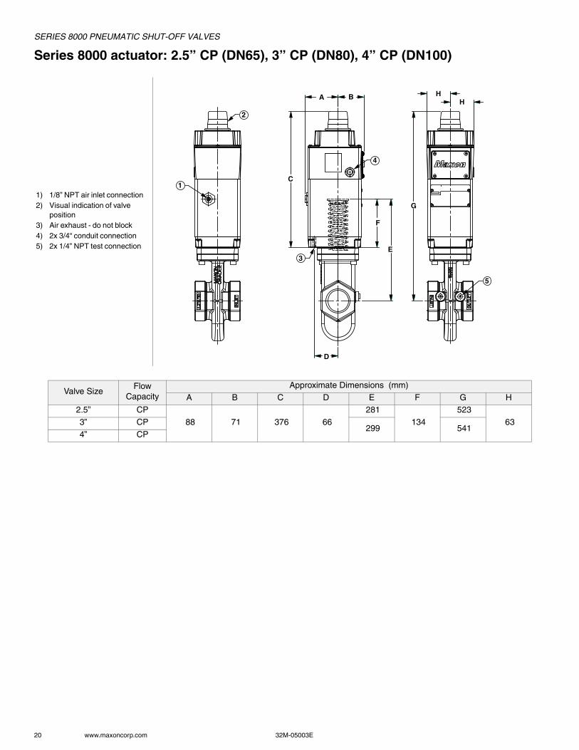
Series 8000 actuator: 2.5” CP (DN65), 3” CP (DN80), 4” CP (DN100)
1) 1/8” NPT air inlet connection2) Visual indication of valve
position3) Air exhaust - do not block4) 2x 3/4“ conduit connection5) 2x 1/4” NPT test connection
Valve SizeFlow
CapacityApproximate Dimensions (mm)
A B C D E F G H2.5” CP
88 71 376 66
281
134
523
633” CP 299 541
4” CP
1
A B
D
E
F
C
H H
G
2
4
3
5

SERIES 8000 PNEUMATIC SHUT-OFF VALVES
32M-05003E 21
Series 8100 valve body: 2.5” CP, 3” CP, 4” CP
1) 2x 1/4” NPT test connec-tion
Body Connection A & C Body Connection B, D & H
Body Connection E Body Connection F & G
Valve Size
FlowCapacity
BodyConnection
Body/BonnetMaterial
Approximate Dimensions (mm)Approximate Weight
(kg)
H K LNØ
PØ
RØ
S# of
holes
BodyAssembly
ActuatorAssembly
TotalWeight
2.5”C
A, C
Cast Iron
109 63 127 N/A 8
5
14
B
114 96 190
177 139 194
14 19
D 185 144 19 14 19
H 185 144 19 8 14 19
BCarbon Steel & Stainless Steel
177 139 194
15 21
D 185 144 18 15 21
H 185 144 18 8 15 21
C G CS & SS 112 155 312 190 150 22 8 18 23
3”C
A, C
Cast Iron
129 71 139 N/A 12 18
B
132 101 203
190 152 19 4 21 27
D, H 200 160 19 8 21 27
B Carbon Steel & Stainless Steel
190 152 19 4 22 28
D, H 200 160 18 8 22 28
C G CS & SS 132 168 338 211 168 22 8 25 30
4”C
BCast Iron
139 114 228
228 190 19
8
29 35
D, H 220 180 19 29 35
B Carbon Steel & Stainless Steel
228 190 19 30 36
D, H 220 180 18 30 36
C G CS & SS 130 188 389 254 200 22 8 38 43
Flow Capacity:S - StandardC - CP Body Construction
Body Connection:A - NPTB - ANSI Flanged (ISO 7005 PN20)C - ISO 7-1 ThreadedD - DIN PN16 FlangedE - Socket Welded NipplesF - Socket Welded Nipples w/ Class 150 Flange (ISO 7005 PN20)G - Socket Welded Nipples w/ Class 300 Flange (ISO 7005 PN50)H - EN1092-1 PN16 (ISO 7005-1 PN16)
L K
H
1
R S
N
H
K L
P
1
L K
H
1
R S
L
N
K
H
P
1

SERIES 8000 PNEUMATIC SHUT-OFF VALVES
22 www.maxoncorp.com 32M-05003E
Series 8100 actuator: 2.5” CP, 3” CP, 4” CP
1) 1/8” NPT air inlet connection2) Visual indication of valve
position3) Air exhaust - do not block4) 2x 3/4” conduit connection5) 2x 1/4” NPT test connection
Valve SizeFlow
CapacityApproximate Dimensions (mm)
A B C D E F G H2.5” CP
114 83 414 91
309
162
561
763” CP 327 579
4” CP
1
A B
D
E
F
H H
C
G
2
4
3
5

SERIES 8000 PNEUMATIC SHUT-OFF VALVES
32M-05003E 23
Series 8000 and 8100: 6” and 8”
1) 1/8” NPT air inlet connec-tion
2) Visual indication of valve position
3) 1/8” NPT air exhaust - do not block
4) 2x 3/4” conduit connection5) 2x 1/4” NPT test connec-
tion
Valve Size
FlowCapacity
Body Conn.
Body/BonnetMaterial
Approximate Dimensions (mm) Approximate Weight (kg)
A B C D E H J K L M NØ
PØ
RØ
S#of
holes
BodyAssembly
ActuatorAssembly
TotalWeight
6” S
BCast Iron
116 83 91 165 76 218 840 133 266 553
279 241 22
8
53
10
63
D, H 284 241 21 53 63
B Carbon Steel & Stainless Steel
279 241 22 57 67
D 284 241 21 57 67
8” S
BCarbon Steel & Stainless Steel 116 83 91 165 76 218 840
146 292553
342 298 22 8 77
10 88
D, H 340 295 21 12
J 146 292 380 330 25 12 98 108
Flow Capacity:S - Standard
Body Connection:B - ANSI 150 lbs (ISO7005 - PN20)D - DIN PN16 FlangedH - EN1092-1 PN16 (ISO 7005-1 PN16)J - ANSI Class 300 Flange (ISO 7005 PN50)
1
3
2
4
5
N
RS
A B C
M
D
E E
L K
H
J
P INLET
OUTLET

SERIES 8000 PNEUMATIC SHUT-OFF VALVES
24 www.maxoncorp.com 32M-05003E
ACCESSORIESSPEED CONTROL SET
Manually adjustable valve restricts flow to the actuator inlet and so reduces opening speed of the normally-closed shut-off valve or reduces the closing speed of normally-open vent valves.• Available in carbon steel and stainless steel construction
• 90° mating elbow provided for easy assembly• Tamper-proof set screw prevents accidental misadjustment
Carbon Steel construction Stainless Steel construction
1) Speed control adjustment knob
Speed Control Set A B C D E
Carbon Steel 142 106 33 66 25Stainless Steel 157 116 43 71 25
AB
CD
E1

SERIES 8000 PNEUMATIC SHUT-OFF VALVES
32M-05003E 25
EXTERNAL REDUNDANT SOLENOID WITH MANUAL RESETCombination of both external redundant solenoids and manual reset option. If either solenoid trips, the valve will close and cannot be reset until it is done manually at the site of the valve before operations can resume.
EXTERNAL REDUNDANT SOLENOIDDual shut-off solenoids provide additional SIL 2 certification levels to offer a higher level of protection against potential solenoid failure. The double redundant solenoid valve will automatically trip as a series shut-down mode and will close or open the valve (depending on set-up) if either of the solenoid valves trip.
1) Manual reset latching pin
2) Manual reset button3) 1/8” NPT exhaust filter
(do not block)4) Speed control
(optional)5) Speed adjustment lock
screw6) Speed control adjust-
ment knob7) 1/8” NPT air inlet con-
nection
A B C D E F
190 68 124 91 53 135
General Purpose Intrinsically Safe
Solenoid type A B C D E FGeneral Purpose 182 132 --- 25 55 25
Intrinsically Safe 182 130 150 25 96 10
A
B
CD
E
1
2
34
5
6
7
F
A
B D
E
F
AB
C
D
E
F

SERIES 8000 PNEUMATIC SHUT-OFF VALVES
26 www.maxoncorp.com 32M-05003E
EXTERNAL REDUNDANT SOLENOID WITH SPEED CONTROL SETCombination of both external redundant solenoids and speed control set option. If either solenoid trips, the valve will close and cannot be reset until it is done manually. Speed control set features manually adjustable valve that restricts flow to the actuator inlet and so reduces opening speed of the normally-closed shut-off valve or reduces the closing speed of normally-open vent valves.
INTRINSIC SAFETY INTERFACESApproved units interposed between the hazardous and safe area circuits limit parameters such as voltage, current or power. • Suitable for use in Class I, Div. 2 areas• DIN rail mounted
• Complements intrinsically safe Series 8000 Valves
General Purpose Intrinsically Safe
Solenoid type / speed control set type A B C D E F G HGeneral Purpose / carbon steel 132 56 68 28 25 13 220 132
General Purpose / stainless steel 132 56 71 28 25 13 226 132
Intrinsically Safe / stainless steel 130 --- 71 43 25 --- 226 ---
Engineering recommendations for barriers and isolator optionManufacturer IS interface type Model no. Application MAXON no.
MTLZener Diode [1]
MTL 7728+ Solenoid 1067656
MTL 7787+ Switch [2] 1067655
Isolator [3]MTL 5025 Solenoid 1067660MTL 5018 Switch [4] 1067659
[1] Circuit must be isolated from earth in hazardous area[2] Two barriers required for VOS1 / VCS1[3] Circuit may be earthed at one point in hazardous area[4] One barrier required for VOS1 / VCS1
A
B
CD
E
F
G
H
A
DC
E G

SERIES 8000 PNEUMATIC SHUT-OFF VALVES
32M-05003E 27
INSTALLATION, OPERATION AND MAINTENANCE INSTRUCTIONS
Please read the operating and mounting instructions before using the equipment. Install the equipment in compliance with the prevailing regulations.
Bedrijfs- en montagehandleiding voor gebruik goed lezen! Apparaat moet volgens de geldende voorschriften worden geïnstalleerd.
Lire les instructions de montage et de service avant utilisation! L’appareil doit imperativement être installé selon les règlementations en vigueur.
Betriebs- und Montageanleitung vor Gebrauch lesen! Gerät muß nach den geltenden Vorschriften installiert werden.

SERIES 8000 PNEUMATIC SHUT-OFF VALVES
28 www.maxoncorp.com 32M-05003E
DESCRIPTIONThe Series 8000 Valve is a pneumatically operated fuel shut-off valve. These valves require compressed air for actuation. The 8000 Series valve will open or close by the addition of a control voltage signal. Removal of the signal will cause a fast acting return to the at rest position.Options are available in both normally-closed and normally-open versions.
Series 8*1* Normally-Closed will shut off flow when de-energized and pass flow when energized.
Series 8*2* Normally-Open will shut off flow when energized and pass flow when de-energized.
The Series 8000 Valve has optional configurations that meet hazardous locations.
The Series 8000 Valve has fire safe trim configurations that meet API 6FA.
NAMEPLATE AND ABBREVIATIONSConsult the nameplate on your valve. This lists the maximum operating pressure, temperature limitations, voltage requirements and service conditions of your specific valve. Do not exceed nameplate ratings.
The Installation, Operating and Maintenance Instructions contain important information that must be read and followed by anyone operating or servicing this product. Do not operate or service this equipment unless the instructions have been read. IMPROPER INSTALLATION OR USE OF THIS PRODUCT COULD RESULT IN BODILY INJURY OR DEATH.
Abbreviation or Symbol DescriptionM.O.P. or MOPD (PS) Maximum Operating Pressure or Maximum Operating Pressure Differential
PACT Required actuator pressure
TS(AMB) Ambient service temperature range
TS(FL) Fluid service temperature range
Visual indication determined by text, color and symbol; valve is shown in open position
Visual indication determined by text, color and symbol; valve is shown in closed position
Valve is shut
Valve is partially open
Valve is full open
VOS-1/2 Valve open switch(es)VCS-1/2 Valve closed switch(es); proof of closure

SERIES 8000 PNEUMATIC SHUT-OFF VALVES
32M-05003E 29
Component identification
1) Flow arrow2) Visual indication3) Terminal block cover screws, M5 x 124) Switch access cover5) Terminal block cover6) Actuator bolts, M8 x 45 or M10 x 1.507) Valve body8) Actuator9) Switch access cover screws, M6 x 2010) Nameplate11) Nameplate screws, M4 x 6
4
2
9
3
10
1
5
8
6
7
11

SERIES 8000 PNEUMATIC SHUT-OFF VALVES
30 www.maxoncorp.com 32M-05003E
Installation1. A gas filter or strainer of 40 mesh (0.6 mm maximum) or greater is recommended in the fuel gas piping to protect the downstream
safety shut-off valves.2. Properly support and pipe the valve in the direction of the flow arrow on the valve body. Valve seats are directional. Sealing will be
maintained at full rated pressures in one direction only. Sealing will be provided in reverse flow only at reduced pressures.3. Mount valve so that open/shut indicator will not face downward.4. Series 8000 Valves require clean, dry compressed air or gas piped to the inlet of the actuator. Guidelines for various actuating gases:
A. Compressed Air1. The vent, located on the underside of the base plate, should be protected from blockage.2. Although MAXON Series 8000 Valves do not require lubrication, they do contain Buna-N (-40°C) or silicone (-50°C) seals in
the actuator sub-assembly. Compressed air supply must not contain any lubricant that is not compatible with Buna-N or silicone elastomers.
B. Natural gas and other fuel gases can be used to actuate the Series 8000 Valve when the appropriate considerations are taken into account. 1. Apply only the Intrinsically Safe Series 8000 Valve for the application. The general purpose and non-incendive options are
not suitable for fuel gas activation.2. The activating fuel gas must be clean and free of moisture. The Series 8000 actuator contains Buna-N elastomers and brass
components that will come in contact with the activating gas. The quality of the gas must not contain any constituents that are not compatible with Buna-N or brass.
3. The exhaust gas must be vented to the atmosphere in a safe manner by piping from the filtered vent, located on the underside of the actuator’s base. A 1/8” NPT female connection in the base plate allows for proper piping.
4. The use of fuel gases for actuation is not permitted in EC areas due to ATEX Zone 2 restrictions.5. Actuators for fuel gas activation are only rated from -40°C to 60°C.
C. For applications that are governed by the ATEX Directive (94/9/EC), use of fuel gas activation is not acceptable.5. In some instances, it may be desired to utilize a slow opening feature for either application or code-related reasons. If a slow opening
feature is required for normally-closed shut-off valves, use MAXON’s optional speed control set.6. Wire the valve in accordance with all applicable local and national codes and standards. In U.S. and Canada, wiring must conform to
the NEC ANSI/NFPA 70 and/or CSA C22.1, Part 1.A. Supply voltages must agree with valve’s nameplate voltage within -15%/+10% for proper operation. For electrical wiring
schematic, see instructions or sample affixed inside valve terminal block cover.B. Grounding is achieved with a grounding screw, which is located in the top assembly.C. Customer connections are provided via terminal block located in the top assembly.D. Main power wiring (120 VAC or 240 VAC) must be segregated from lower voltage 24 VDC signal wiring, when both are required.E. WARNING: For Division 2 installations using the intrinsically safe solenoid, the power source is not to exceed 28VDC with a
minimum series resistance of 300 ohms.7. Maintain integrity of the Series 8000 actuator enclosure by using the appropriate electrical connectors for the (2) 3/4” NPT conduit
threaded connections.The Series 8000 electrical enclosure is NEMA 4 and IP65 rated with an option for NEMA 4X.A.To eliminate any potential for gas to enter the electrical wiring system, install a conduit seal fitting at the actuator conduit hub.
8. All access cover plate screws should be tightened using an alternate cross-corner tightening pattern to the values shown in Table 1.
9. Verify proper installation and operation by electrically actuating the valve for 10-15 cycles prior to the first introduction of gas.
10.When customer-supplied, externally mounted solenoids are used, the component must be rated for the Class and Division of the hazardous area. MAXON 8112, 8122, 8012, 8022 valves will only carry FM approval to FM 3611, 3600 and 3810 standards. MAXON 8113, 8123, 8013, 8023 valves will only carry FM approval to 3610, 3600 and 3810 standards.
Table 1 - Torque SpecificationsItem Number Description Torque
3 Terminal Block Cover Screws, M5 x 12 2.25 N.m
9 Switch Access Cover Screws, M6 x 20 2.25 N.m6 Actuator Bolts, M8 x 45 17.6 N.m
6 Actuator Bolts, M10 x 1.50 17.6 N.m
11 Nameplate Screws, M4 x 6 1.13 N.m

SERIES 8000 PNEUMATIC SHUT-OFF VALVES
32M-05003E 31
SPECIFICATIONSValve Body Assemblies
Valve Size Flow CapacityActuator Pressure
Class
Body ConnectionsAvailable [1]
BodyMaterial
Cv Rating
Flow Rate [2] MOP/MOPD
.75”(DN 20)
Std.High
Pressure
A, C Iron
19 1060 / 30
200/13.8
A, C, E, F, GSteel
255/17.6Stainless
1”(DN 25)
Std.High
Pressure
A, C Iron
20 1115 / 31
200/13.8
A, C, E, F, GSteel
255/17.6Stainless
1.25”(DN 32)
Std.HIgh
PressureA, C Iron 45 2510 / 71 200/13.8
1.5”(DN 40)
Std.High
Pressure
A, C Iron
53 2956 / 83
200/13.8
A, C, E, F, GSteel
255/17.6Stainless
2”(DN 50)
Std.High
Pressure
A, B, C, D, H Iron
86 4796 / 135
200/13.8
A, C, E, F, GSteel
255/17.6Stainless
2.5”(DN 65)
Std.High
PressureA, B, C, D, H Iron 127 7083 / 200 150/10.3
CP
Std.
A, B, C, D, H Iron
304 16955 / 480
50/3.4B, D, H
Steel
Stainless
HighPressure
A, B, C, D, H Iron
175/12.1B, D, H
Steel
Stainless
3”(DN 80)
Std.High
PressureA, C Iron 173 9648 / 273 150/10.3
CP
Std.
A, B, C, D, H Iron
423 23591 / 668
40/2.7B, D, H
Steel
Stainless
HighPressure
A, B, C, D, H Iron
135/9.3B, D, H
Steel
Stainless
4”(DN 100)
CP
Std.
B, D, H
Iron
490 27328 / 773
40/2.7Steel
Stainless
HighPressure
Iron
135/9.3Steel
Stainless
6”(DN 150)
Std.
Std.
B, D, H
Iron
1172 65364 / 1850
60/4.1Steel
Stainless
HighPressure
Iron
100/6.9Steel
Stainless
8”(DN 200)
Std.
Std.
B, D, H, J
Steel
1320 73406 / 2078
60/4.1Stainless
High Pressure
Steel100/6.9
Stainless
Note 1: Body ConnectionsA - NPTB - ANSI 150 lb Flange (ISO 7005 PN 20)C - ISO ThreadedD - DIN PN16 Flange
E - Socket Welded NippleF - Socket Welded Nipple w/ANSI 150 lb flange (ISO 7005 PN20)G - Socket Welded Nipple w/ANSI 300 lb flange (ISO 7005 PN50)H - EN 1092-1 PN16 (ISO 7005-1 PN16)J - ANSI Class 300 Flange (ISO 7005 PN50)
Note 2: Flow for Natural Gas (S.G. 0.60) at differential pressure = 2.5 mbar and standard temperature (15°C) and pressure (1.013 bar)
cfhm3 h------------- psig
bar-----------

SERIES 8000 PNEUMATIC SHUT-OFF VALVES
32 www.maxoncorp.com 32M-05003E
OPERATING CHARACTERISTICS• Opening time varies with valve size, air pressure, temperature, and fuel pressure. Typically about 3 seconds for larger sizes and down
to approximately 1 second for smaller valves. For slower opening, a speed control set can be supplied by MAXON.
• Closing time is less than 1 second for all sizes, regardless of application parameters.• Type of Gas
AUXILIARY FEATURES• Non-adjustable Proof of Closure Switch(es) with valve seal over travel interlock.
• Auxiliary switch for indication of full travel (open for normally-closed valves, closed for normally-open valves).
GasGas
Code
Suggested Material Options
MOPDRating
Agency Approvals and Certifications
Seals & BumperBody & Bonnet
[7]Trim Option [5] FM
CSA [3]
CE [4]GAD [6]
PED [7]
Air AIR A, B, C, F 1, 2, 5, 6 1, 2, 3, 6, 7 Std. X X X
Ammonia AMM A, C, F 1, 2, 5, 6 1, 2, 3, 6, 7 Std. X X X
Butane Gas BUT A, B, F 1, 2, 5, 6 1, 2, 3, 6, 7 Std. X X X XCoke Oven Gas COKE B, F 5 Analysis Required Std. X X X
Delco DEL A, B, F 1, 2, 5, 6 1, 2, 3, 6, 7 Std. X X X
Digester [1] DIG Analysis Required 5 Analysis Required Std. X X XEndothermic AGA ENDO A, B, F 1, 2, 5, 6 1, 2, 3, 6, 7 Std. X X X
Exothermic Gas EXO A, B, F 1, 2, 5, 6 1, 2, 3, 6, 7 Std. X X X
Hydrogen Gas HYD A, B, C, F 1, 2, 5, 6 1, 2, 3, 6, 7 Reduced [2] X X XManufactured [1] MFGD Analysis Required 5 Analysis Required Std. X X X
Natural Gas NAT A, B, F 1, 2, 5, 6 1, 2, 3, 6, 7 Std. X X X X
Nitrogen NIT A, B, C, F 1, 2, 5, 6 1, 2, 3, 6, 7 Std. X X XOxygen (High P) OXYH B, C, F 2, 5, 6 4, 5 13 bar X X X
Oxygen (Low P) OXYL B, C, F 1, 2, 5, 6 4, 5 2 bar X X X
Oxygen X OXYX B, C, F 2, 5, 6 4, 5 Std. X X XPropane PROP A, B, F 1, 2, 5, 6 1, 2, 3, 6, 7 Std. X X X X
Refinery [1] REF Analysis Required 5 Analysis Required Std. X X X
Sour Natural Gas [1] SOUR Analysis Required 5 Analysis Required Std. X X XTown Gas [1] TOWN Analysis Required 5 Analysis Required Std. X X X X
Land Fill Gas [1] LAND Analysis Required 5 Analysis Required Std. X X X
Notes:[1] Other body and trim packages may be acceptable pending fuel analysis. For pricing inquiries, Viton or Omniflex o-rings should be used. Contact MAXON for details.[2] Valve maximum operating pressure differential (MOPD) to be reduced by 25% from standard ratings.[3] ISO connections are not recognized by CSA or UL standards.[4] 8000 Series electro-pneumatic valves meet the essential requirements of the Low Voltage - LVD (2006/95/EC), Electromagnetic Compatibility - EMC (2004/108/EC), Gas Appliances - GAD (2009/142/EC), and Pressure Equipment - PED (97/23/EC) Directives.[5] Trim Option 1 is only allowed with Body and Bonnet Option 1.[6] The Gas Appliance Directive only covers the use of commercially available fuels (natural gas, butane, town gas and LPG).[7] PED certification limited to 1-1/2" (DIN 40) through 4" (DIN 100) valves with steel or stainless steel body options (2, 5, 6). Body option 2 has a min ambient temp of -29°C.
Body Seals:A - Buna-NB - VitonC - Ethylene PropyleneF - Omniflex
Body & Bonnet:1 - Cast Iron2 - Carbon Steel5 - Stainless Steel6 - Low Temp Carbon Steel
Trim Package:1 - Trim Package 12 - Trim Package 23 - Trim Package 3 (NACE)4 - Trim Package 2, Oxy Clean5 - Trim Package 3, Oxy Clean6 - Trim 2 fire safe7 - Trim 3 fire safe

SERIES 8000 PNEUMATIC SHUT-OFF VALVES
32M-05003E 33
OPERATING ENVIRONMENT• Fluid temperature range of -40°C to 100°C, with options available for -50°C to 100°C.• Actuators are rated for NEMA 4, IP65 or optional NEMA 4X, IP65.
• Ambient temperature range of -40°C to 60°C for the 8011, 8111, 8021 and 8121 General Purpose and 8012, 8112, 8022 and 8122 Non-Incendive series valves; option of -50°C to 60°C also available.
• Ambient temperature range of -40°C to 50°C for 8013, 8113, 8023 and 8123 Intrinsically Safe series valves; option of -50°C to 50°C also available.
• All valves for oxygen service or using Ethylene Propylene body seals are limited to a minimum ambient and fluid temperature of -17°C.

SERIES 8000 PNEUMATIC SHUT-OFF VALVES
34 www.maxoncorp.com 32M-05003E
PRODUCT APPROVALS
����������� ������� ������ ����������������� ���������������������������� ���������������������������� ���� ���������������������������� ����
���� �� !��"��# ���� �� !��"��# ���� �� !��"��#
$!�%������� �������
����� ���� � ���
&�%�������������� �������
�������� ��� �������� ��� �������� ���
����� ���� � ��� ����� ���� � ���
�'&�%������� ��� ��� ���
����� ���� � ���
()* ����� ���� � ���
%�%�&������������ ������� ��� ������� ��� ������� ���
����� ����! ��"���#�����$��%��&�'&��(
)�*���+ ������,��+��"���-��, .��/0��1�2�#�����$��%��&�&��(
)'*�3-��� ��+�.�-���� �"��4� �� ��+5��6���� 7�" ��+�� ���+5���28��9���5�9���5�9���5�9����$� $���.� �� 7�����7��������$� �
���'���5�'������+�'9������+��+��
)�*�3-��� ��+�.�-���� �"��4� �� ��+5��6���� 7�" ��+�� ���+5���28��9��'5�9��'5�9��'5�9��'�$� $���.� �� 7�����7��������$� �
���'���5�'������+�'9������+��+��
+��,����� ���-+��,����"��#������
����������'������'������'9��
� ����:5�#�$��5�;� ����<�#5�1�� ����::5�#�$��5�;� ����;5�1�
� ����:::5�#�$��5�1��6�������::�����������������������������������������
1��1��=�4�����>����;��:���
����������'������'������'9��
� ����:5�#�$��5�;� ����<�#5�1�� ����::5�#�$��5�;� �����;5�1�
� ����:::5�#�$��5�1��6����::��1��1��=�4�����>����:����
$!�%������� ,�'&'.�&������������
:��������4�:��������4��
�6�������::�����������������������������������������1��1��=�4�����>��?��;��:���
�6���:::��1�'�?��#���;������'�2
:��������4�:��������4��
�6����::��1��1�=�4��?���>��?��:����6���:::��1���?��1�=�4��?���>��?�
��;������'�2
���������������������'�������������������������4�����������4��
� ����:5�#�$��5�;� ����<�#5�1�� ����::5�#�$��5�;� ����;5�1�
� ����:::5�#�$��5�1��6����::��1��1��=����%.�-����+��+�� ���+(
%@���������$� (�6����::��1��1��=����
%.�-�:��� ���+(%@���������$� (
�����������������������������������������������4�����������4��
� ����:5�#�$��5�;� ����<�#5�1�� ����::5�#�$��5�;� �����;5�1�
� ����:::5�#�$��5�1��6����::��1��1��=����%@���������$� (
'�������%������� ����
����������'���
�A&BA0��5�;C������:�0���9�����
����������'���
�A&BA0��5�;C������:�0���9�����
����������'���
�A&BA0��5�;C������:�0���9�����
'�������%������� ����/0�1�� � �*������� 2
��������4���������4������������������4������'��'4�����'��'4�
::���;������6����::��1�1�=4�����>����:���
::���#������6���#����:����1���D�1�=4�����>��D������1�2��'�
:��������4�:�������9
:��������4�:�������9
:��������4�:�������9
+&&-��3����
�<�1��<C�:��������4�:��������4��:��������4'�
�6�������::��1��;�%4���?��E�1��E�>���?�(�6���:::��1�'�?��#�
:���
�<�1��<C�:��������4��<�1��<C�:��������4��:��������4'�
�6����::��1��;�%4���?��E�1��E�>���?�(�6���:::��1�'�?��#�
:���
��� ���"����������4'��,�������7�,��"� 7"�����+�A���
�6�������::��1�&1��6���:::��1�'�?��:���%4��?��E�1��E�>��?(
��� ���"����������4'��,�������7�,��"� 7"�����+�A���
�6����::��1�%4��?��E�1��E�>��?�(
)�*���+ ���"� ����.�-�-��������� ���! ���"����,�-��, .��/0�;������ ������#�����$��%����&���&��(F�A.�G �/��#�����$��%����&��&��(F�����#�����$��%����&��9&��(F�
�������������
������
�������������
��� �
������
���
������

SERIES 8000 PNEUMATIC SHUT-OFF VALVES
32M-05003E 35
VALVE CYCLE REQUIREMENTSThis is based on the standards that MAXON valves are approved to and the corresponding minimum number of cycles to be completed without failure as shown in the chart below.
CSA (CSA 6.5) FM (FM 7400) European (EN161)Automatic - Normally-ClosedSeries 8011, 8111, 8012, 8112, 8013, 8113 100,000 20,000
<= 1” 200,000<= 3” 100,000<= 8” 50,000
Vent ValvesSeries 8021, 8121, 8022, 8122, 8023, 8123
No specialrequirements
No specialrequirements
No specialrequirements
SERIES 8000 PNEUMATIC SHUT-OFF VALVES
36 www.maxoncorp.com 32M-05003E
ELECTRICAL DATA
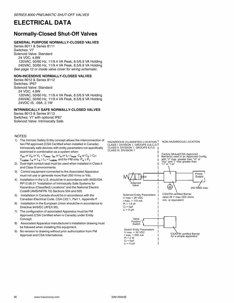
Normally-Closed Shut-Off ValvesGENERAL PURPOSE NORMALLY-CLOSED VALVESSeries 8011 & Series 8111Switches: V7Solenoid Valve: Standard
24 VDC, 4.8W120VAC, 50/60 Hz, 11/9.4 VA Peak, 8.5/6.9 VA Holding240VAC, 50/60 Hz, 11/9.4 VA Peak, 8.5/6.9 VA Holding
See page 12 or inside valve cover for wiring schematic.
NON-INCENDIVE NORMALLY-CLOSED VALVESSeries 8012 & Series 8112Switches: IP67Solenoid Valve: Standard
24 VDC, 4.8W120VAC, 50/60 Hz, 11/9.4 VA Peak, 8.5/6.9 VA Holding240VAC, 50/60 Hz, 11/9.4 VA Peak, 8.5/6.9 VA Holding24VDC IS, .09A, 2.1W
INTRINSICALLY SAFE NORMALLY-CLOSED VALVESSeries 8013 & Series 8113Switches: V7 with optional IP67Solenoid Valve: Intrinsically Safe
NOTES:1) The Intrinsic Safety Entity concept allows the interconnection of
two FM approved (CSA Certified when installed in Canada) Intrinsically safe devices with entity parameters not specifically examined in combination as a system when:Voc or Uo or Vt ≤ Vmax, Isc or Io or It ≤ Imax, Ca or Co ≥ Ci+ Ccable, La or Lo ≥ Li + Lcable, and for FM only: Po ≤ Pi.
2) Dust-tight conduit seal must be used when installed in Class II and Class III environments.
3) Control equipment connected to the Associated Apparatus must not use or generate more than 250 Vrms or Vdc.
4) Installation in the U.S. should be in accordance with ANSI/ISA RP12.06.01 “Installation of Intrinsically Safe Systems for Hazardous (Classified) Locations” and the National Electric Code® (ANSI/NFPA 70) Sections 504 and 505.
5) Installation in Canada should be in accordance with the Canadian Electrical Code, CSA C22.1, Part 1, Appendix F.
6) Installation in the European Union should be in accordance to Directive 94/9/EC (ATEX 95).
7) The configuration of associated Apparatus must be FM Approved (CSA Certified when in Canada) under Entity Concept.
8) Associated Apparatus manufacturer’s installation drawing must be followed when installing this equipment.
9) No revision to drawing without prior authorization from FM Approval and CSA International.
HAZARDOUS (CLASSIFIED) LOCATION NON-HAZARDOUS LOCATIONCLASS I, DIVISION 1, GROUPS A,B,C,DCLASS II, DIVISION 1, GROUPS E,F,GCLASS III, DIVISION 1
Factory Mutual/CSA ApprovedBarrier(s) used in an Approved Config.with “V” max. greater than “VI” or“Voc” and “I” max greater than“I t” or “I sc”
PowerSupply
250 RMS max.
CSA/FM certified Barrier
“CSA/FM certified Barrierfor a simple apparatus”
SolenoidValve
Solenoid Entity ParametersV max = 28 VDCI max. = 115 mAPi = 1.6 WCi = 0µFLi = 0 µH
ValvePositionSwitch
Switch Entity ParametersV max. = 30 VDCI max. = 500 mAPi = 2 WCi = 0µFLi = 0 µH
rated 28 V max./300 ohmsmin. or equivalent

SERIES 8000 PNEUMATIC SHUT-OFF VALVES
32M-05003E 37
INTRINSICALLY SAFE NORMALLY-CLOSED VALVESSeries 8013 & Series 8113
Switches: V7 with optional IP67
Solenoid Valve: Customer-supplied, externally mounted
NOTES:1) The Intrinsic Safety Entity concept allows the interconnection of two
FM approved (CSA Certified when installed in Canada) Intrinsically safe devices with entity parameters not specifically examined in combination as a system when:Voc or Uo or Vt ≤ Vmax, Isc or Io or It ≤ Imax, Ca or Co ≥ Ci+ Ccable, La or Lo ≥ Li + Lcable, and for FM only: Po ≤ Pi.
2) Dust-tight conduit seal must be used when installed in Class II and Class III environments.
3) Control equipment connected to the Associated Apparatus must not use or generate more than the maximum permissible safe area voltage (Um) for the barrier.
4) Installation in the U.S. should be in accordance with ANSI/ISA RP12.06.01 “Installation of Intrinsically Safe Systems for Hazardous (Classified) Locations” and the National Electric Code® (ANSI/NFPA 70) Sections 504 and 505.
5) Installation in Canada should be in accordance with the Canadian Electrical Code, CSA C22.1, Part 1, Appendix F.
6) Installation in the European Union should be in accordance to Directive 94/9/EC (ATEX 95).
7) The configuration of associated Apparatus must be FM Approved (CSA Certified when in Canada) under Entity Concept.
8) Associated Apparatus manufacturer’s installation drawing must be followed when installing this equipment.
9) No revision to drawing without prior authorization from FM Approval and CSA International.
Powersupply
see note 3
Factory Mutual/CSA ApprovedBarrier(s) used in an Approved con-figuration with "V" max. greater than "Vt"or "Voc" and "I" max. greater than "I t" or "I sc"
HAZARDOUS (CLASSIFIED) LOCATIONCLASS I, DIVISION 1, GROUPS A,B,C,DCLASS II, DIVISION 1, GROUPS E,F,GCLASS III, DIVISION 1
Customer Supplied Solenoid Valve-To be mounted external to valve actuator.-Component must be rated for the Class and Division of the hazardous environment as stated above.-Component must be rated for instrinsic safety and be interconnected with other intrinsically safe devices as required under the Intrinsic Safety Entity Concept (see note 1).
NON-HAZARDOUS LOCATION
Solenoid Valve
"CSA/FM/ATEX certified Barrier for a simple apparatus"
Switch Entity Parameters
V max.=30 VDCI max.=500 mAPi= 2 WCi= O µFLi= O µH
ValvePositionSwitch

SERIES 8000 PNEUMATIC SHUT-OFF VALVES
38 www.maxoncorp.com 32M-05003E
Normally-Open Vent ValvesGENERAL PURPOSE NORMALLY-OPEN VENT VALVESSeries 8021 & Series 8121Switches: V7Solenoid Valve: Standard
24 VDC, 4.8W120VAC, 50/60 Hz, 11/9.4 VA Peak, 8.5/6.9 VA Holding240VAC, 50/60 Hz, 11/9.4 VA Peak, 8.5/6.9 VA Holding
See page 12 or inside valve cover for wiring schematic.
NON-INCENDIVE NORMALLY-OPEN VENT VALVESSeries 8022 & Series 8122Switches: IP67Solenoid Valve: Standard
24 VDC, 4.8W120VAC, 50/60 Hz, 11/9.4 VA Peak, 8.5/6.9 VA Holding240VAC, 50/60 Hz, 11/9.4 VA Peak, 8.5/6.9 VA Holding24VDC IS, .09A, 2.1W
INTRINSICALLY SAFE NORMALLY-OPEN VENT VALVESSeries 8023 & Series 8123Switches: V7 with optional IP67Solenoid Valve: Intrinsically Safe
NOTES:1) The Intrinsic Safety Entity concept allows the interconnection of
two FM approved (CSA Certified when installed in Canada) Intrinsically safe devices with entity parameters not specifically examined in combination as a system when:Voc or Uo or Vt ≤ Vmax, Isc or Io or It ≤ Imax, Ca or Co ≥ Ci+ Ccable, La or Lo ≥ Li + Lcable, and for FM only: Po ≤ Pi.
2) Dust-tight conduit seal must be used when installed in Class II and Class III environments.
3) Control equipment connected to the Associated Apparatus must not use or generate more than 250 Vrms or Vdc.
4) Installation in the U.S. should be in accordance with ANSI/ISA RP12.06.01 “Installation of Intrinsically Safe Systems for Hazardous (Classified) Locations” and the National Electric Code® (ANSI/NFPA 70) Sections 504 and 505.
5) Installation in Canada should be in accordance with the Canadian Electrical Code, CSA C22.1, Part 1, Appendix F.
6) Installation in the European Union should be in accordance to Directive 94/9/EC (ATEX 95).
7) The configuration of associated Apparatus must be FM Approved (CSA Certified when in Canada) under Entity Concept.
8) Associated Apparatus manufacturer’s installation drawing must be followed when installing this equipment.
9) No revision to drawing without prior authorization from FM Approval and CSA International.
HAZARDOUS (CLASSIFIED) LOCATION NON-HAZARDOUS LOCATIONCLASS I, DIVISION 1, GROUPS A,B,C,DCLASS II, DIVISION 1, GROUPS E,F,GCLASS III, DIVISION 1
Factory Mutual/CSA ApprovedBarrier(s) used in an Approved Config.with “V” max. greater than “VI” or“Voc” and “I” max greater than“I t” or “I sc”
PowerSupply
250 RMS max.
CSA/FM certified Barrier
“CSA/FM certified Barrierfor a simple apparatus”
SolenoidValve
Solenoid Entity ParametersV max = 28 VDCI max. = 115 mAPi = 1.6 WCi = 0µFLi = 0 µH
ValvePositionSwitch
Switch Entity ParametersV max. = 30 VDCI max. = 500 mAPi = 2 WCi = 0µFLi = 0 µH
rated 28 V max./300 ohmmin. or equivalents

SERIES 8000 PNEUMATIC SHUT-OFF VALVES
32M-05003E 39
INTRINSICALLY SAFE NORMALLY-OPEN VENT VALVESSeries 8023 & Series 8123
Switches: V7 with optional IP67
Solenoid Valve: Customer-supplied, externally mounted
NOTES:1) The Intrinsic Safety Entity concept allows the interconnection of two
FM approved (CSA Certified when installed in Canada) Intrinsically safe devices with entity parameters not specifically examined in combination as a system when:Voc or Uo or Vt ≤ Vmax, Isc or Io or It ≤ Imax, Ca or Co ≥ Ci+ Ccable, La or Lo ≥ Li + Lcable, and for FM only: Po ≤ Pi.
2) Dust-tight conduit seal must be used when installed in Class II and Class III environments.
3) Control equipment connected to the Associated Apparatus must not use or generate more than the maximum permissible safe area voltage (Um) for the barrier.
4) Installation in the U.S. should be in accordance with ANSI/ISA RP12.06.01 “Installation of Intrinsically Safe Systems for Hazardous (Classified) Locations” and the National Electric Code® (ANSI/NFPA 70) Sections 504 and 505.
5) Installation in Canada should be in accordance with the Canadian Electrical Code, CSA C22.1, Part 1, Appendix F.
6) Installation in the European Union should be in accordance to Directive 94/9/EC (ATEX 95).
7) The configuration of associated Apparatus must be FM Approved (CSA Certified when in Canada) under Entity Concept.
8) Associated Apparatus manufacturer’s installation drawing must be followed when installing this equipment.
9) No revision to drawing without prior authorization from FM Approval and CSA International.
Powersupply
see note 3
Factory Mutual/CSA ApprovedBarrier(s) used in an Approved con-figuration with "V" max. greater than "Vt"or "Voc" and "I" max. greater than "I t" or "I sc"
HAZARDOUS (CLASSIFIED) LOCATIONCLASS I, DIVISION 1, GROUPS A,B,C,DCLASS II, DIVISION 1, GROUPS E,F,GCLASS III, DIVISION 1
Customer Supplied Solenoid Valve-To be mounted external to valve actuator.-Component must be rated for the Class and Division of the hazardous environment as stated above.-Component must be rated for instrinsic safety and be interconnected with other intrinsically safe devices as required under the Intrinsic Safety Entity Concept (see note 1).
NON-HAZARDOUS LOCATION
Solenoid Valve
"CSA/FM/ATEX certified Barrier for a simple apparatus"
Switch Entity Parameters
V max.=30 VDCI max.=500 mAPi= 2 WCi= O µFLi= O µH
ValvePositionSwitch

SERIES 8000 PNEUMATIC SHUT-OFF VALVES
40 www.maxoncorp.com 32M-05003E
OPERATING INSTRUCTIONSRefer to appropriate catalog page for operating features applying to your specific valve. Never operate valve until all essential allied equipment is operative and any necessary purges completed. Failure of valve to operate normally indicates that it is not powered or supply air pressure is not adequate. Check this first!
Main system shut-off should always be accomplished with an upstream leak-tight manual fuel cock.
Users are responsible for providing protection against surface temperatures.Users are responsible for providing suitable protective devices to protect against over pressure conditions.Users are responsible for limiting momentary pressure surges to within 10% of the maximum allowed pressure in accordance with the Pressure Equipment Directive.
• Normally-closed shut-off valves begin opening cycle immediately upon being powered.
• Normally-open vent valves begin to close immediately upon being powered.
The Series 8000 Pneumatic Safety Shut-off Valve is not intended to be used for end of line service.

SERIES 8000 PNEUMATIC SHUT-OFF VALVES
32M-05003E 41
ALTERNATE OPERATOR PRESSURESSeries 8000 Valves may be operated within a range of actuator pressures. Consult charts below for application fluid pressure and corresponding required actuator pressure.

SERIES 8000 PNEUMATIC SHUT-OFF VALVES
42 www.maxoncorp.com 32M-05003E

SERIES 8000 PNEUMATIC SHUT-OFF VALVES
32M-05003E 43
MAINTENANCE INSTRUCTIONSMAXON Series 8000 Valves are endurance tested far in excess of the most stringent requirements of the various approval agencies. They are designed for long life even if frequently cycled, and to be as maintenance-free and trouble-free as possible.
A valve operational test should be performed on an annual basis. If abnormal opening or closing is observed, the valve should be removed from service and your MAXON representative should be contacted. (See Valve Technical Data page 10-35.1.)
Valve leak test should be performed on an annual basis to assure continued safe and reliable operation. Every MAXON valve is operationally tested and meets the requirements of FCI 70-2 Class VI Seat Leakage when in good operable condition. Zero leakage may not be obtained in the field after it has been in service. For specific recommendations on leak test procedures, see MAXON Valve Technical Data page 10-35.2. Any valve that exceeds the allowable leakage, as set forth by your local codes or insurance requirements, should be removed from service and your MAXON representative should be contacted.
Actuator assembly components require no field lubrication and should never be oiled.
Auxiliary switches, solenoids or complete actuator may be replaced in the field.
If foreign material or corrosive substances are present in the fuel line, it will be necessary to inspect the valve to make certain it is operating properly. If abnormal opening or closing is observed, the valve should be removed from service. Contact your MAXON representative for instructions.
Operator should be aware of and observe characteristic opening/closing action of the valve. Should operation ever become sluggish, remove valve from service and contact MAXON for recommendations.
Address inquiries to MAXON. Local worldwide offices may be located at www.maxoncorp.com or by phoning 011-765-284-3304.
Include valve serial number and nameplate information.
Do not attempt field repair of valve body or actuator. Any alterations void all warranties and can create potentially hazardous situations.
Specific conditions of use: Clean the enclosure only with a damp cloth to prevent the accumulation of electrostatic charges.

SERIES 8000 PNEUMATIC SHUT-OFF VALVES
44 www.maxoncorp.com 32M-05003E
Solenoid replacement procedure• All power sources, both pneumatic and electric, must be de-energized and follow all proper safety procedures prior to servicing valve.
• Use a 4 mm allen wrench to remove the top plate. A 3 mm allen wrench is used to remove the terminal block cover.
• Use a 5/16” open end wrench to hold the cylinder shaft, then use a pair of pliers to unthread the switch indicator from the cylinder shaft. When using pliers, grab the indicator from the top.
• Loosen the liquid tight connector nut where the solenoid wires come into the top housing. Remove #1 and #2 wire from the terminal block.
1) Top plate screw M6 x 20 socket head cap screw
2) M6 Lock washer3) Top plate4) Switch indicator5) Cylinder shaft6) Terminal block cover7) M5 Lock washer8) Terminal block cover
screw M5 x 12 socket head cap screw
1) Liquid tight connector
1
2
3
4
5
6
78
1

SERIES 8000 PNEUMATIC SHUT-OFF VALVES
32M-05003E 45
• Use a 3/4” wrench to remove the solenoid inlet fitting. An adjustable wrench is used to loosen the housing collar. Slightly loosen the housing collar but do not remove, due to the nut and o-ring located inside the housing becoming dislocated.
• Use a 4 mm allen wrench and remove the 4 screws that hold the housing to the base plate. Pull the housing straight up and remove. Old solenoid wires will pass through liquid tight connector.
• Use a 4 mm allen wrench and remove the 2 screws that hold the solenoid on. Replace the solenoid ensuring that there are 2 o-rings, one on the solenoid inlet and one on the solenoid outlet. The solenoid must be level when tightening screws.
1) Housing collar2) Solenoid inlet fitting
1) Housing 2) Base plate3) Housing screws M6 x 20
cap screws
1) Solenoid o-ring2) Solenoid3) M5 x 40 socket head cap
screw4) Solenoid o-ring
1
2
1
2
3
12
3
4
SERIES 8000 PNEUMATIC SHUT-OFF VALVES
46 www.maxoncorp.com 32M-05003E
• Run the new solenoid wires back up through the liquid tight connector in the housing and align the cylinder shaft with the hole in the housing. Carefully slide housing back into position. Replace the 4 housing screws and leave loose.
• Verify the o-ring is still on the solenoid inlet by looking through the housing collar. Reinstall solenoid inlet fitting tight. Leave the housing collar loose.
• Reinstall solenoid wire #1 and #2 back to the terminal block and tighten down the liquid tight connector nut.• A locking sealant must be used on the cylinder shaft threads and then reinstall the switch indicator. Make sure to remove any locking
sealant that runs down the cylinder shaft. Re-energize pneumatic and electric power and cycle the valve several times to ensure it operates smoothly. Tighten down the 4 housing screws that hold the housing to the base plate using a cross pattern (see torque val-ues in Table 1 on page 30). Then tighten the housing collar on the solenoid inlet fitting. The o-ring under the housing collar must not be pinched while tightening the housing collar.
• Cycle valve several more times to see if it still operates smoothly. If not, loosen the 4 screws that hold the housing to the base plate and cycle again. Retighten the 4 housing screws. Put the top plate and terminal block covers back on valve (see torque values in Table 1 on page 30).

SERIES 8000 PNEUMATIC SHUT-OFF VALVES
32M-05003E 47
Actuator assembly rotation/replacement
• Shut off all electrical power and close off upstream manual cock.
• Remove terminal block access cover plate [4] and disconnect power lead wires. Caution: Label all wires prior to disconnection when servicing valve. Wiring errors can cause improper and dangerous operation.
• Remove conduit and electrical leads.
• Remove all pneumatic lines.
• Unscrew the actuator/body bolts [5] screwed up from the bottom. These bolts secure the valve actuator [7] to the valve body [6].• Gently lift the actuator [7] off valve body assembly enough to break the seal between body assembly and the rubber gasket adher-
ing to the bottom of the actuator base plate. • Carefully rotate/replace actuator assembly to the desired position. Reposition the actuator back down onto the valve body casting.
• Realign holes in valve body casting with the corresponding tapped holes in the bottom of the actuator base plate. Be sure the gasket is still in place between the body and actuator base plate.
• Reinsert the body bolts up from the bottom through the body and carefully engage threads of the actuator assembly. Tighten securely referring to Table 1 on page 30 for appropriate torque specifications.
• Reconnect conduit, electrical leads, and all pneumatic lines, then check that signal switch wands are properly positioned. Failure to correct any such misalignment can result in extensive damage to the internal mechanism of your valve.
• Energize valve and cycle several times from closed to full open position. Also electrically trip the valve in a partially opened position to prove valve operates properly.
• Replace and secure cover plates.
• Verify proper operation after servicing.
Note 1: Open/Shut indication is 360°. If required, the observation window may be cleaned with a damp cloth.
MAXON Series 8000 Valves should be ordered in a configuration compatible with planned piping. If valve orientation is not correct, the actuator assembly can be rotated in 90° increments around the valve body centerline axis using the procedure below. This procedure should also be followed for field replacement of the actuator.
1) Flow arrow on valve body2) Open/shut indicator (see
Note 1 below)3) Switch access cover4) Terminal block cover and
screws5) Actuator/body bolts6) Valve body7) Actuator assembly8) Switch access cover
screws
1
5
2
38
4
7
6

SERIES 8000 PNEUMATIC SHUT-OFF VALVES
48 www.maxoncorp.com 32M-05003E
Field installation of valve position switch
General: Shut off fuel supply upstream of valve, then de-energize valve electrically.Remove top cover and terminal block cover to provide access, being careful not to damage gasket.See pages 48 and 49 for instructions on adding or replacing switches.
FIELD REPLACEMENT ITEMS• Position Switches
• Actuators
• Solenoids
Contact MAXON with valve serial numbers to locate appropriate switch kit assembly.
REPLACEMENT SWITCHES:• Carefully remove field wiring from the terminal block (see page 29, item 5). Insure field wires are clearly marked to correct terminal.
• Unwire the solenoid valve lead wires from terminals labeled #1 and #2.• Remove screws that secure the switch sub-assembly to the actuator housing. The switch sub-assembly should be easily removable
from actuator assembly (see Figure 3: Typical Switch Sub-Assemblies).• Note wand position and mounting hole location. Carefully remove the 2 screws and lift existing switch. Reference Figures 4 through 9
(page 49) to ensure correct switch location.• Install replacement switch in same mounting holes on bracket and verify correct wand position.
• Replace existing wiring one connection at a time, following original route and placement.
• Reassemble switch sub-assembly in actuator housing. Dowel pins are provided to insure proper placement of switch sub-assembly.• Wire the solenoid valve leads to terminals labeled #1 and #2.
• Cycle valve, checking switch actuation points carefully. VCS switch actuates at top of stem stroke and VOS at bottom for normally-closed shut-off valves; vice-versa for normally-open vent valves.
• Replace covers using torque values in Table 1 on page 30, and then return valve to service.
Instructions below are written for normally-closed shut-off valves. For normally-open vent valves, reverse switch nomenclature. (VOS becomes VCS and vice versa.)
Substitution of components may affect suitability for Hazardous Locations.
Figure 3: Typical switch sub-assemblies
V7 assembly for General Purpose and Intrinsically Safe valves
IP67 Switch assembly for Non-Incendive and optional Intrinsically Safe valves

SERIES 8000 PNEUMATIC SHUT-OFF VALVES
32M-05003E 49
ADD SWITCHES:• Carefully remove field wiring from the terminal block (see page 29, item 5). Insure field wires are clearly marked to correct terminal.• Unwire the solenoid valve lead wires from terminals labeled #1 and #2.
• Remove screws that secure the switch sub-assembly to the actuator housing. The switch sub-assembly should be easily removable from actuator assembly (see Figure 3: Typical Switch Sub-Assemblies).
• Reference Figures 4 through 9 (below) to ensure correct switch location. Valve size is depicted in the model number by the first 4 dig-its. For example, a 3” CP valve should have Model No. 300C.
• Install switch and insulators, when provided, to correct hole. Insure proper alignment. VCS switch should have activation wand pointed upward and VOS activation wand should be pointed downward.
• Wire new switches to terminals provided.
• Reassemble switch sub-assembly in actuator housing. Dowel pins are provided to insure proper placement of switch sub-assembly.
• Wire the solenoid valve leads to terminals labeled #1 and #2.• Cycle valve, checking switch actuation points carefully. VCS switch actuates at top of stem stroke and VOS at bottom for normally-
closed shut-off valves; vice-versa for normally-open vent valves.• Replace covers using torque values in Table 1 on page 30, and then return valve to service.
Figure 4:IP67 Switch Bracket
Figure 5:IP67 Switch Bracket
Figure 6:General PurposeSwitch Bracket
Figure 7: General PurposeSwitch Assembly
Figure 8:6” & 8” Valve IP67
Switch Bracket
Figure 9:6” & 8” Valve General
Purpose Switch Bracket
.75”, 1”, 1.25”, 1.5”2”, 2.5” & 3” VCS
.75” & 1” VOS
1.25” VOS
1.5” VOS
2”, 2.5” & 3” VOS
2.5”CP, 3”CP, 4”CP
2.5”CP VOS
3”CP, 4”CP
.75”, 1”, 1.25”, 1.5”2”, 2.5” & 3” VCS
.75” & 1” VOS
1.25” VOS
1.5” VOS
2”, 2.5” & 3” VOS
2.5”CP, 3”CP, 4”CP
2.5”CP VOS
3”CP, 4”CP

SERIES 8000 PNEUMATIC SHUT-OFF VALVES
50 www.maxoncorp.com 32M-05003E
IEC 61508 INSTRUCTION REQUIREMENTSPRODUCT DESCRIPTIONA Failure Mode, Effects, and Diagnostics Analysis (FMEDA) report is available from MAXON. Detailed failure rate data is available in the FMEDA reports. Data for Series 8000 Valves with internal solenoids only can be found in Exida Report MAX 08/09-07 R002. Data for Series 8000 Valves with internal solenoid and redundant external solenoid can be found in Exida Report MAX 1208063 R002.
PRIMARY SAFETY FUNCTIONa. Series 8*1*, Normally Closed will pass flow when energized and shut off flow within the stated leakage specification when de-
energized.b. Series 8*2*, Normally Open will pass flow when de-energized and shut off flow within the stated leakage specification when
energized.c. The valves are designed for low demand applications.d. The valve must be within specified operating conditions, as found in the instruction manual.
PROOF TESTThe objective of proof testing is to detect failures within the Series 8000 Valve that prevent the valve from performing its safety function.
The frequency of proof testing, or the proof test interval, is to be determined in reliability calculations for the safety instrumented functions for which the Series 8000 Valve is applied. The proof tests must be performed more frequently or as frequently as specified in the calculation in order to maintain the required safety integrity of the safety instrumented function.
Maintenance instructions include a Valve Leak Test. These instructions must be followed during the proof test. This Valve Leak Test will detect approximately 99% of possible DU (Dangerous Undetected) failures resulting in a Proof Test Coverage of 99% for the valve. For specific recommendations on leak test procedures, see MAXON Valve Technical Document 10-35.2-1.
The person(s) performing the proof test of the Series 8000 Valve should be trained in SIS (Safety Instrumented Systems) operations, including bypass procedures, valve maintenance and Company Management of Change procedures.
If implementing partial stroke testing of Series 8000 Valves, see MAXON PSCheck documentation (Form Number 32M-05004) for diagnostic coverage information related to Series 8000 Valves.
RELIABILITY DATA AND LIFETIME LIMITA detailed Failure Mode, Effects, and Diagnostics Analysis (FMEDA) report is available from MAXON. This report details all failure rates and failure modes, common cause factors for applications with redundant devices and the expected lifetime of the Series 8000 Valve.
a. The Series 8000 Valve is intended for low demand mode applications up to SIL 3 for use in a simplex (1oo1) configuration, depending on the PFDAVG calculation of the entire Safety Instrumented Function.
b. The development process of the Series 8000 Valve is certified up to SIL 3, allowing redundant use of the valve up to this Safety Integrity Level, depending on the PFDAVG calculation of the entire Safety Instrumented Function.
c. When using the Series 8000 Valve in a redundant configuration, a common cause factor should be included in reliability calcu-lations. For details, see the FMEDA report.
d. The reliability data listed in the FMEDA report is only valid for the useful lifetime of the Series 8000 Valve. The failure rates of the Series 8000 Valve may increase sometime after this period. Reliability calculations based on the data listed in the FMEDA report for mission times beyond the lifetime may yield results that are too optimistic, i.e. the calculated Safety Integrity Level will not be achieved.
PRODUCT SAFETY OFFICERAny failures that are detected and that compromise functional safety should be reported to the Product Safety Officer within MAXON. Please contact MAXON Customer Service.

SERIES 8000 PNEUMATIC SHUT-OFF VALVES
32M-05003E 51
FITTING CERTIFICATE
We:
Maxon Corporation
Address:
201 E. 18th Street
Muncie, IN 47302
USA
Declare that all fittings produced at the above address within the following product group:
Maxon Series 8000 Air Actuated Valves
Conform to all applicable provisions of the European Gas Appliance Directive.
Certification: Product Identification Number C86CM45 applies
EC Surveillance: BSI (Notified Body Number 0086)
This certificate issued by: Maxon Corporation
Name: Lora Davis
Title/Position: Product Engineering Manager
Date of issue: April 15, 2011

Commercial & Industrial Combustion (C&IC)
Honeywell
MUNCIE, INDIANA, USAMaxon201 East 18th StreetP.O. Box 2068Muncie, IN 47307-0068Tel: 765.284.3304Fax: 765.286.8394
GOLDEN VALLEY, MINNESOTA, USAHoneywell Automation and Control Solutions1985 Douglas Drive NorthGolden Valley, MN 55422-3992www.honeywell.com
Canada Sales OfficeTORONTOMaxon Industrial Equipment3333 Unity DriveMississauga, Ontario L5L 3S6Tel: 800.489.4111Fax: 855.262.0792
European Sales OfficeBELGIUMMaxon International BVBALuchthavenlaan 16-181800 Vilvoorde, BelgiumTel: 32.2.255.09.09Fax: 32.2.251.82.41
Asia/Pacific Sales OfficeSINGAPOREMaxonHoneywell Building17 Changi Business Park, Central 1Singapore 486073Tel: 65.6580.3358Fax:65.6580.3345
China Sales OfficeSHANGHAIMaxon Combustion Equipment(Shanghai) Co., Ltd.1st Floor & Section A, 4th Floor225 Meisheng RoadWai Gao Qiao Free Trade ZonePudong New AreaShanghai 200131, P.R. ChinaTel: 86.21.5866.1166Fax:86.21.5868.1569
India Sales OfficePUNEMaxon53, 54, 56, 57 Hadapsar Industrial EstateEnvironmental & Combustion ControlsSapphire Building 2nd Floor, A WingPune 411013 IndiaTel: 91.98.50907894Tel: 91.20.66008330Tel: 91.20.66008509Fax: 91.20.66039979
Sales Offices &Representatives Worldwide
maxoncorp.comcustomer.honeywell.com
32M-05003E - Metric versionMaxon P/N 50111985-001/C01February 2016 Printed in USA© 2016 Honeywell International Inc.