Pneumatic Seeder Air 8 - Opico · Pneumatic Seeder Air 8 OPICO LIMITED South Road, Bourne, Lincs,...
43
2012 2012 omas Hatzenbichler Agro-Technik GmbH Fischering 2, A-9433 St. Andrä Tel: +43 (0) 4358/2287 Fax: +43 (0) 4358/2208 E-mail: [email protected] Manual Manual and and spare parts catalog spare parts catalog Pneumatic Seeder Air 8 Pneumatic Seeder Air 8 OPICO LIMITED South Road, Bourne, Lincs, PE10 9LG Tel.: 01778 / 42 11 11 – Fax: 01778 / 42 50 80 [email protected] – www.opico.co.uk
Transcript of Pneumatic Seeder Air 8 - Opico · Pneumatic Seeder Air 8 OPICO LIMITED South Road, Bourne, Lincs,...

20122012Th omas Hatzenbichler Agro-Technik GmbHFischering 2, A-9433 St. AndräTel: +43 (0) 4358/2287Fax: +43 (0) 4358/2208E-mail: [email protected]
Manual Manual andand
spare parts catalogspare parts catalog
Pneumatic Seeder Air 8Pneumatic Seeder Air 8
OPICO LIMITEDSouth Road, Bourne, Lincs, PE10 9LGTel.: 01778 / 42 11 11 – Fax: 01778 / 42 50 [email protected] – www.opico.co.uk

Page 1
contents
Seite1. EC Declaration of Conformity ........................................................................................ 2
2. Safety information ............................................................................................................... 3
3. Intended Use ........................................................................................................................ 4
4. Accident prevention ........................................................................................................... 4
5. Germination requirements ................................................................................................ 5
6. Warranty .............................................................................................................................. 5
7. Installation instructions .................................................................................................... 6
8. Note for the operation ........................................................................................................ 9
9. Work at the fi eld .................................................................................................................. 13
10. Before start working ......................................................................................................... 13
11. Care and Maintance ......................................................................................................... 14
12. Storage in winter ............................................................................................................... 14
13. Description the meter calibration .................................................................................. 15
14. Conversion chart .............................................................................................................. 17
15. Turn off the agitator shaft ................................................................................................ 18
16. Spare parts catalog Air 8................................................................................................... 19

Page 2

Page 3
Second. Safety information:
Before starting,read the instruction manual and note.
When attaching the machine and during operation of the hydraulic folding sure that no one in between.
Beware of high pressure fl uid escaping!
Th e transport of the ma-chine is prohibited!
Th e stay in the danger zone is permitted only if a memory Hubzylindersi-cherung or safety support!
Stay clear of swinging ran-ge folding machine parts!
Never reach into the crushing area as long as parts may move!
the stripper is to be che-cked prior to each start of work

Page 4
third. Intended Use
Dear Customer!
We are pleased to congratulate you on your buying decision and wish you much fun and success in working with this device.
Please read necessarily before using this product all the instructions in this manual carefully.
Th is will avoid, reduce risks, downtime and repair costs, increase reliability and service life of your machine.
With illustrations and information on technical data and dimensions in this manual changes designed to improve, are reserved.
4th. Accident prevention• The General accident prevention regulations of each country are taken into account.• When is arrival and uncoupling the machine to the hitch of the tractor injury.• The unit must be secured to prevent accidental switching off when rolling.• The device may only be used by anyone on the regulations for public transport streets know.• The attached machine before hanging off the ground.
Th e machine is equipped with state of the art and the recognized securities safety rules. Nevertheless, results from the use of injury to the user or third parties.
Th e only machine in perfect working condition for its intended purpose, safety andrisk of danger with respect to use of the manual!
In particular, problems that can aff ect safety must be corrected immediately.
Th e machine may only be used by individuals, maintained and repaired, who are familiar with and aware of the danger.
Th e installation or modifi cation of products can not Hatzenbichler constructively givenCharacteristics of the machine to change negative and thereby impair the safety of man and machine.
Th e machine is designed for normal use for cultivation in the agricultural sector determined. Any other or additional use is considered improper.
Shall not be liable for damages resulting from Hatzenbichler.Th e risk is borne entirely by the user.
Intended use also includes compliance with the instruction manual and the adherence to the manufacturer‘s instructions for operation, maintenance and maintenance requirements.

Page 5
Th e company assumes no liability for Hatzenbichler the germination of seeds.
Grounds:
We lack any ability to predict the following factors: fi rst soil second State of the seed third Depth of sowing 4th Preparation of the soil before application 5th Was built on what device the seeder
Instructions for installation and operation of the device:Th e calibration test must be performed by the operator in the fi eld.
„Air 8“ - pneumatic seed drill with 8 hoses to over-or reseeding to 6,50m working width. For sowing in the fi eld plowed to 3.00 m working width.
„Air 16“ - pneumatic seed drill with 16 hoses to over- or reseeding 12m working width. For sowing in plowed fi eld to 6m working width.
5th Germination requirements
6th. Warranty
Th e unit immediately upon acceptance check for possible shipping damage. Subsequent complaints from transit damage can not be accepted.
We give a one year warranty from date of shipment (your invoice or delivery note as proof of valid).Th is warranty is valid in the case of material or construction failure and does not cover parts that are damaged by normal-or excessive wear.
Th e warranty is void• if damage is caused by external forces• when an operation error• if the specifi ed KW/horsepower limit is exceeded• if the device is changed without our consent, extended, or is equipped with foreign parts.

Page 6
7th Air 8 - Installation Instructions7.1 PNEUMATIC SEEDER
1. Th e support provided to the pneumatic seeder mounted behind the headstock.
2. Th e Seedbox on this mount bracket build such that the electric blower and the metering device to the rear point and the seed tubes forward lead to the distributor hoses.
3. Th e operator platform should be behind the seed box and positioned as desired.
4. Respect them in the setting of seed retention brush
7.2 TAIL WHEEL1. Th e wheel is mounted with the included locating on the lower hole in the rear parking stand. Th e cable should have the right hose.2. Th e bracket for the cable conduit is mounted right on the roller suspension.
7.3 DISTRIBUTOR TUBES
1. Remove the plastic caps on the front of the carrier, perform the mounting bracket all the way into the pipe and tighten the screw.2. Carrier distribution profi le of C-insert into the mounting bracket, and 20 to 40cm above the ground set.3. Distribution hoses with the supplied screws on the carrier C-section at a distance of approximately 37.50 cm place.4. Hoses and trim used between Saatkastenauslass and distribution plate, tubing it out so that when hydraulic folding (if any) are not the hoses clamped be.
Working width Distance distributor hoses
3,00m 37,50cm4,50m 56,25cm5,00m 62,50cm6,00m 75,00cm6,50m 81,25cm

Page 7
7.4 POWER OF THE BLOWER
Th e fans need 12V/30A directly from the battery of the tractor. Th e two fans are separately connected to the battery. When connecting, make sure that the fan running in the right direction, ie in plan view in a clockwi-se direction.
1. Power cable (see Figure 1) connect directly to the tractor battery put on / off switch and 7-pin connector in the cab.2. Th e cable of the Seeding machine has a 7-pin socket which is connected to the power cord of the tractor.3. Th e supplied cable has the positive wire to the battery via two series fuses (16 A).
Ari 8 electric

Page 8
Air 8 mechanical
monitor unit for air 8 mechanical drive item code: 1918030002
cable set for Air 8 mechanical item code: 1918030001

Page 9
8th Note for the operation
2. basic settings
Before fi lling the seed box, note the following:
1. Th e correct seed shaft is installed?
Attention!!! Th e drill shaft must be according to the size of the seed and authorizations for future Amount to be elected!
Seed, which is applied to the coarse seed shaft :
grass seed mixtures, rye, barley, wheat, oats, etc.(usually small amounts, 10kg/ha - ≥)
Seed, the seed shaft is applied with the fi ne:
Pure clover seed, rape, phacelia, granules, etc. (usually small amounts, 15kg/ha ≤ - ≥)
3. Setting the seed retention brush:
Th e distance between the retaining brush from the seed shaft can be adjusted with the lever on the right side of the pneumatic Seeding machine. It is possible a distance between 1 and 7mm to choose.
It is, however, note the following:Th e distance between the brush and roller corresponds to about 1/2 of seedmeans the oilseed rape, clover 0,1mm grass mixtures 1-2mm Ground cover and feed mixtures 2-3mmTh e gap at the bottom of the drill shaft should never be more than 1mm (factory setting).
Lever for adjusting the retaining brush
ding to the size of the seed and authorizations for
rough seed roller
fi ne seed roller
8.1 basic settings for the Cover of the seed hopper
• Before start seeding check if the cover of the seed hopper ist closed with the handle.• Check the screw of the cover of the seed hopper if it´s fi xed
d

Page 10
8.2 Changing the seed roller:
1. Ensure that the seed box is completely empty2. To replace the right side to be on the pneumatic seed drill, the bearing support of the end cap to be removed.3.Pull out the role - so, while the counterclockwise turn and pull.
Installation of a new seed roller:
1. New push seed roller shaft to the drive axle.
2. Replace the bearing bracket in place.
3. Aft er insertion of the bearing holder should the spring washers at the ends of the seed shaft existing balance game
Attention!!! the slices should not sit tight
4. Trail wheel and make sure that the drill shaft to rotate properly.
opening the Bearing support of the closing fl ap by thumbscrew
Pull out the seed roller
New seed roller shaft to the drive axle
Th e bearing retainer refi t using the thumb screws
Page 11
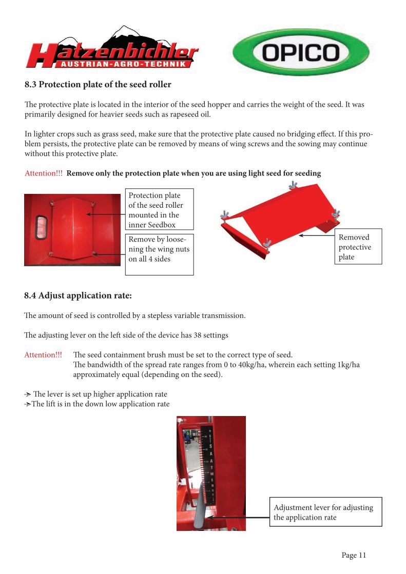
8.3 Protection plate of the seed roller
Th e protective plate is located in the interior of the seed hopper and carries the weight of the seed. It was primarily designed for heavier seeds such as rapeseed oil.
In lighter crops such as grass seed, make sure that the protective plate caused no bridging eff ect. If this pro-blem persists, the protective plate can be removed by means of wing screws and the sowing may continue without this protective plate.
Attention!!! Remove only the protection plate when you are using light seed for seeding
8.4 Adjust application rate:
Th e amount of seed is controlled by a stepless variable transmission.
Th e adjusting lever on the left side of the device has 38 settings
Attention!!! Th e seed containment brush must be set to the correct type of seed. Th e bandwidth of the spread rate ranges from 0 to 40kg/ha, wherein each setting 1kg/ha approximately equal (depending on the seed).
• Th e lever is set up higher application rate•The lift is in the down low application rate
Adjustment lever for adjusting the application rate
Protection plate of the seed roller mounted in the inner Seedbox
Remove by loose-ning the wing nuts on all 4 sides
Removed protective plate

Page 12
8.5 Drive
Trail wheel:Solved before the start of sowing spure from the transport position and let down to the ground. Th e wheel in working position is also in constant contact with the ground fl oor irregularities. If the device is lift ed, the pin holding the lever under the wheel away from the ground.
drive cableTh e cable conduit is fed to the struts in such a way that kinking.
Attention: Th e direction of the wheel can not be reversed.
8.6 Calibrate
1. Put away the cover of the seed roller 2. Calibration tank to insert into the tray of running roller3. Trail wheel 50x rotate anticlockwise
Attention!!! Th e wheel shoulded turnde faster than in real work 4. Quantity of seed delivered to within a scale.5. Th e measured weight in the formula to use. _____________10.000m²_______________ x weight= amount kg/ha (wheel diameter x revolutions x working width)
Example:Wheel diameter = 1,35m 10.000 m² x 0,6kg =14,8 kg/haRevolutions = 50 (1,35x50x6)Working width = 6mDischarged amount of seed =0,6kg
7. By moving the lever (upward or downward) can be connected to the left side of the device the amount per hectare can be set.8. Repeat calibration until the desired application rate is reached.
e lever under the wheel away f
ed f d h
1. 1. 2. 3.

Page 13
8.7 Drain the Seedbox
• Th e calibration tank into the compartment (as well as performing the calibration)• Th e lever for adjusting the maximum spray rate and retention brush (on the right side). and set the spure clockwise until the Seedbox is empty.• In complete emptying of the seedbox the seed roller must also be removed.
9th Working at the fi eld
Litter:Old pastures can be optimized by applying new seed. Preparing the old fl oor with the harrow, so that cost-eff ective broadcast seeding can be done. Th e combined use of pneumatic seeder VERTIKATOR and makes the most of every litter program, because at the same time fi ghting weeds, aerates the soil and the conditions for germination are optimized.
Overseeding:The seeding has the advantage of clearly higher yields and improved feed quality. Seeding on cultivated soil with the harrow and the pneumatic sowing machine easy to handle. However some points to consider:• Determined before application of the pH, phosphate and potassium content of the soil.• Th e seedbed should be fi ne and fi rm• Seeding depth observed
Intercropping:It is also possible aft er harvest in stubble intercrop, the application of a pneumatic seeder Air 8. For example, the installation of a disc harrow or Hatzenbichler Delta.
10th Before start working:• Operation of both fans and the true direction?• It is recommended to allow both fans run briefl y to allow for any moisture in the Distributor tubing to dry. Th us, the risk that reduces clog the tubes.• It should be min. 10kg seed in the seed box.•The lid of the hopper to the air.• Th e distribution tubes 20 - 40cm above the ground set.• Check all hoses to ensure uniform output across the entire width to guarantee.

Page 14
11th Care and Maintenance• Electric fan with compressed air, especially in dusty environments.
• Check cables and connectors for damage.
• Check whether the mixer is clean and ready.
• Damage or wear study. Any defects rectifi ed immediately.
• Check nuts and bolts regularly for tightness and tighten if necessary. (On new units every 3 hours and again aft er 20 hours.)
• Do not use high pressure washers for cleaning bearings and hydraulic parts used.
12th Storage in winter• Th e completely empty Seedbox
• Completely and thoroughly cleaned
• Off device protected from the weather cover, so that the distribution pipes and the dosing may accumulate moisture.

Page 15
13th Instructions for calibration

Page 16

Page 17
14th Conversion chart

Page 18
15th Turn off the agitator shaft
• Turning off the agitator shaft is only useful if fi ne seed is spread example clover seed.

Page 19
16th Spare parts catalog for pneumatic seeder „Air 8“

Page 20
item code item number designation930001 1 seeder base „Air 8“93090921 1.1 holding plate for protection plate930002 2 transmission gearbox9300142 3 toothed-belt roller, Z020, Drilling hole 15mm930004 4 transmission protection guard9300041 4.1 toothed-belt roller, Z=20, Drilling hole 15mm930033 4.2 sticker for scale930006 6 lever long for seed rate94061K 8.1 clutch complete9300101 10 tensioner pulley9406K 10.1 clamp for tensioner pulley9406F 10.2 guiding for tensioner pulley9406S 10.3 screw M8x100930012 12 bearing9300131 13 extension shaft for transmission930096 13.1 fi tting key 4x4x20mm9300141 14 toothed-belt roller, Z=36, Drilling hole 12mm93000811 15 toothed belt AT 5-525mm9300211 21.1 cover plate rubber seal, 90° 300mm long930028 28 mouting plate „Air 8“39474 28.1 holder for calibration tray94937 29 mounting clamp930034 34 lock complete for cover (bolt with handle) M8x5094985 35 fan blower Air 8 electrical drive949851 35 fan blower Air 8 mechanical drive - 2013930037 37 platic clamp 1, size 3930039 39 allen screw M8x40930040 40 tenons930041 41 threaded pin930042 42 hexagonal screw M6x20930043 43 washer M6930044 44 stop nut M6930045 45 coiled spring pin 5x22930046 46 connection930047 47 threaded shaft M8x409316 48 hexagonal screw M5x10930043 48.1 washer M6930237 48.3 big washer M870012 49 stop nut M8930050 50 hexagonal screw M8x16930051 51 hexagonal screw M12x3070013 52 stop nut M129300572 57.2 hexagonal screw M12x130412124 73 washer M1293000511 42.1 hexagonal screw M6x35
AIR 8 COMPLETE

Page 21
Metering box

Page 22
item code item number designation9310190 4.3 protection guard931187 2.1 elektric motor9300031 3.1 toothed-belt roller, Z=189300141 3.2 toothed-belt roller, Z=36 eith magnet for sensor93001310 5 adapter for electric motor930194 7 screw M5x16930193 7.1 holder for sensor8030341 9 stop nut M44100570 9.1 sensor9120870 9.2 screw M4x204100572 9.3 screw M4x209300128 12.1 bearing 204930096 13.1 fi tting key 4x4x2093000811 15 toothed belt AT5-525mm930042 42 hex bolt M6x20930044 44 stop nut M69316 48 hex bolt M5x10930043 48.1 washer M6
Metering box

Page 23
PLANTING UNIT

Page 24
item code item number designation9300143 8 toothed-belt roller, 30z, Drilling hole 15mm930011 11 hexagonal axle930090 11.1 fi tting key 5x5x20mm930012 12 bearing930018 18 hose distributor, PVC, with 8 holes930019 19 hose clamp930022 22 brush „Air8“930023 23 rod for brush adjustment94984 24 divider plate „Air8“930025 25 seed roller rough „Air8“934822 25.1 seed roller fi ne „Air8“9311041 25.2 foam cover with cap931088E 25.3 end cap for micro roller394751 26 calibration tray „Air8“930027 27 cover9300271 27.1 rubber seal for cover, straight 160mm long9300320 32.1 lever short for brush „Air 8“93000511 42.1 hexagonal screw M6x35930044 44 stop nut M6930043 48.1 washer M6930230 48.2 washer M8930237 48.3 big washer M870012 49 stop nut M8930050 50 hexagonal screw M8x16930053 53 nut M6930054 54 bearing930055 55 end cap assembly complete with bearing, zinc coated9300551 55.1 plastic disc for bearing zinc coated
PLANTING UNIT

Page 25
SEED BOX

Page 26
item code item number designation930030 30 seed hopper „Air8“, 150l9300301 30.1 acrylic glass screen and seal9300491 30.2 Seal outlet930049 30.3 Cover for outlet9310981 30.4 toggle screw M8x1539005 31 hopper lid „Air8“390052 31.1 seal for hopper lid930032 32 blower protection guard93003234 32.1 lever short for blower protection9316 48 hexagonal screw M5x1070012 49 stop nut M8930050 50 hexagonal screw M8x1693003912 50.1 wing bold M8x12930051 51 hexagonal screw M12x3070013 52 stop nut M128009F1 52.1 washer M129300561 56 lid lock galvanised9300570 57 screw M5x109300571 57.1 nut M5
SEED BOX
item code item number designation930092 2xL-part for seed roller protection shield, 4xtoggle screws
M8

Page 27
SEED BOX - NEW 2012complete: 0403010000

Page 28
item code item number designation quantity0403010002 1 draining lid 10403010003 2 cover for Air 8 10403010004 3 bolt lock 10403010005 4 counter plate holder for gas spring 10403010006 5 holder for gas spring 10403010007 6 bearing tube for cover 20403010008 7 gas spring for Air 8 11901010014 8 hexagonal screw M12x70 21904030003 9 circlip 15x1 21902010003 10 hexagonal screw M6x16 21901040001 11 hexagonal screw M5x20 21901010041 12 hexagonal screw M6x16 21908010002 13 washer A13 40403010001 14 container for Air 8 10403010009 15 gasket for cover 11902020002 16 hexagonal nut M6 20403010010 17 gasket for discharge opening 1
SEED BOX - NEW 2012complete: 0403010000

Page 29
COVER - NEW 2012
item code item number designation quantity0403010014 1 pin for closure 11902010003 2 hexagonal nut M12 11901010042 3 hexagonal screw M12x140 11908010002 4 washer A13 11904030005 5 circlip 1
complete: 0403010003

Page 30
SEED SHAFT PROTECTION - NEW 2012SEED SHAFT PROTECTION NEW 2012
item code item number designation quantity0403020002 1 Seed shaft apron 10403020003 2 holder for seed shaft apron 11902070001 3 knurled M8 31902080001 4 butterfl y nut M8 41908010004 5 washer DIN 125 -A8,4 61901010045 6 hexagonal screw M8x35 61902010002 7 hexagonal nut M8 6
complete: 0403020001

Page 31
TRAIL WHEEL

Page 32
item code item number designation930037 37 pipe clamp part930039 39 allen bolt M6x25 plated930041 41 threaded shaft M8x1070013 52 nut M12930065 65 hole plate for trail wheel930052 65.1 hexagonal screw M12x25930066 66 holder for trail wheel930067 67 trail wheel80312SP 67.1 fl ansh for trail wheel70036 67.2 Stop-nut M89300392 67.3 hexagonal screw M8x2560052Z 68.1 bearing 6005 2Z930069 69 distance ring95128 70 roll pin 8x40930224 71 spring pin d=4mm9414 72 glacier bush 20/15930074 74 pin d=14mm930075 75 pin d=10mm930076 76 distance tube, l=4693225 77 hexagonal screw M12x70
TRAIL WHEEL COMPLETE

Page 33
HOSES COMPLETE

Page 34
item code item number designation930039 39 allen bolt M6x25 plated934821 58 fl exible shaft 2,4m9348214 fl exible shaft 2,65m9348215 fl exible shaft 3,0m9348216 fl exible shaft 3,5m9348217 fl exible shaft 4,0m930059 59 seed hose949832 60 distributor931084 61 cable, part 1(from battery, with switch to the plug)931085 62 cable, part 2 (from the plug to the electric motor)949831 81 bracket 25x70x639111 82 C-Profi le/m391011 82.1 C-Profi le, l=1,50m391022 82.2 C-Profi le, l=2,00m80272 83 holder for c-profi le, V6930214 84 hexagonal screw M12x208009F 85 washer M1270018 86 nut M1293935 87 expand bracket 193934 88 expand bracket 2930220 89 allen screw M12x130930219 90 hexagonal screw M12x1309316S 91 hexagonal screw M8x30 m. Mutter70036 91.1 nut M8949833 92 bracket 90x25x6949834 93 bracket to fi t distributor in bed, part 1949835 94 bracket for distributor in bed70017 95 stop nut M10930230 96 washer M8
HOSES COMPLETE

Page 35
item code item number designation9310802 62.1 electro cable (part 2)9310801 62.2 electro cable (part 1)
ELECTRO CABLE

Page 36
HOSE HOLDERHOLDERcomplete: 0401010001
item code item number designation1908010002 1 clamp for tube 80 incl. lock washer1901010036 2 centerpiece for drive shaft holder1901010009 3 management for fl exible shaft 1901010035 4 tail holder for transmission shaft s1902010003 5 fi rst piece for transmission shaft s holder0401020003 6 80s terminal with tooth washer0401010004 7 hexagonal nut M120401010003 8 hex head screw M12x300401020002 9 hex head screw M12x450401010002 10 hex head screw M12x1301913010003 11 washer A 13

Page 37
SENSOR TRAIL WHEEL
complete: 0402010001

Page 38
item code item number designation quantity1918010001 1 sensor for trail wheel 10402010003 2 cover disc for trail wheel 10402010002 3 spacer tube Ø=20x4 l=43,5mm 10402010004 4 cover for sensor 10402010006 5 plate for brake 10402010005 6 sensor wheel loose 10402010007 7 arm for sensor wheel 10402010008 8 brake for sensor wheel 10402010009 9 multi-hole adjustment for sensor wheel 10402010010 10 spacer tube Ø20x4 l=16mm 11903030006 11 connecting pins Ø=10mm, l=75mm 11903030008 12 connecting pins Ø=14mm l=75mm 11906030002 13 deep groove ball bearings DIN 625 -6004 -2RS 21901010010 14 hexagonal screw DIN 931 M12x100 11904020002 15 linch pin Ø=4mm 21904030001 16 circlip DIN 472 -42x1,75 11904030002 17 circlip DIN 472 - 20x1,2 11902050001 18 hexagonal nut M18 21906030003 19 wheel hub for plant protection 11902010003 20 hexagonal nut M12 11902010002 21 hexagonal nut M8 61901070001 22 cylinder screw M6x30 21901010005 23 hexagonal screw M12x25 11901010038 24 hexagonal screw M5x10 41901010039 25 hexagonal screw M6x12 31901010032 26 hexagonal screw M8x25 61912070001 27 Stauff -clamp 21906010001 28 cylindrical socket TFZ2015B 21918020001 29 Brush for sensor wheel 1
SENSOR TRAIL WHEEL

Page 39
HYDRAULIC FANcomplete: 0404010001
HYDRAULIC FANomplete: 0404010001

Page 40
HYDRAULIC FANcomplete: 0404010001
item code item number designation quantity0404010008 1 basket for hydraulik fan 11901080001 2 fl at Head Screw M6x10 71908030001 3 spring ring DIN 127B-10 11901080002 4 fl at Head Screw M4x10 81902010009 5 hexagonal nut M6 50404010009 6 blower half small section 10404010010 7 wings for fan 11902060001 8 hexagonal nut M10 - Linksgewinde 10404010011 9 blower half big section 11902010010 10 hexagonal nut M4 51916020001 11 foam 20x5 l=180mm 31901090001 12 thumbscrew M5x12 30404010012 13 fi lter mat 11912100001 14 blast hose Ø=75mm 11916010002 15 sealing Cap ZK 30/25 11912070002 16 hose clamp 70-90 1

Page 41
MOTOR WITH CLUTCHcomplete: 0404010001

Page 42
complete: 0404010001
item code item number designation quantity1912020012 1 hydraulik hose for hydraulik fan 21912090001 2 shaft for hydraulic fan 10404010002 3 fan holder 11904030002 4 circlip 20x1,2 11904040001 5 wedge AS 6x6x16 10404010003 6 clutch - hub with Ø =20mm 10404010004 7 clutch - sprocket 92 Shore 10404010005 8 clutch- Hub with taper 10404010006 9 hydraulic motor for fan 11901010043 10 hexagonal screw M6x30 41901010044 11 hexagonal screw M5x8 11918010002 12 speed sensor with cable and connector 11906030004 13 deep groove ball bearings - 6204 -22RS 21902010009 14 hexagonal nut M6 30404010007 15 high pressure seal 11904030004 16 circlip 22x1 11912030004 17 screwed 21912040001 18 dust cap red 2
MOTOR WITH CLUTCH