Pneumatic Cylinder - P1D-C Ultra Clean ISO Series ... · Pneumatic Cylinders aerospac e climate...
28
Pneumatic Cylinders aerospace climate control electromechanical filtration fluid & gas handling hydraulics pneumatics process control sealing & shielding Series P1D-C Ultra Clean According to ISO 15552 PDE2642TCUK June 2014
Transcript of Pneumatic Cylinder - P1D-C Ultra Clean ISO Series ... · Pneumatic Cylinders aerospac e climate...
Pneumatic Cylinders
aerospaceclimate control electromechanicalfiltrationfluid & gas handlinghydraulicspneumaticsprocess controlsealing & shielding
Series P1D-C Ultra CleanAccording to ISO 15552PDE2642TCUK June 2014

2
Parker Hannifin CorporationPneumatic Division - Europe
PDE2642TCUK
P1D-C...N Pneumatic ISO Cylinders
SALE CONDITIONSThe items described in this document are available for sale by Parker Hannifin Corporation, its subsidiaries or its authorized distributors. Any sale contract entered into by Parker will be governed by the provisions stated in Parker’s standard terms and conditions of sale (copy available upon request).
WARNING
FAILURE OR IMPROPER SELECTION OR IMPROPER USE OF THE PRODUCTS AND/OR SYSTEMS DESCRIBED HEREIN OR RELATED ITEMS CAN CAUSE DEATH, PERSONAL INJURY ANDPROPERTY DAMAGE.This document and other information from Parker Hannifin Corporation, its subsidiaries and authorized distributors provide product and/or system options for further investigation by users having technical expertise. It is important that you analyze all aspects of your application and review the information concerning the product or system in the current product catalog. Due to the variety of operating conditions and applications for these products or systems, the user, through its own analysis and testing, is solely responsible for making the final selection of the products and systems and assuring that all performance, safety and warning requirements of the application are met. The products described herein, including without limitation, product features, specifications, designs, availability and pricing, are subject to change by Parker Hannifin Corporation and its subsidiaries at any time without notice.
NoteAll technical data in this catalogue are typical data only.Air quality is essential for maximum cylinder service life (see ISO 8573).
ImportantBefore attempting any external or internal work on the cylinder or any connected components, make sure the cylinder is vented and dis connect the air supply in order to ensure isolation of the air supply.
Contents
P1D-C…N – ISO 15552 Cylinders Range .......................................................
EHEDG design principles ................................................................................
Design variants ...............................................................................................
Cylinder forces, double acting variants ...........................................................
Main data .......................................................................................................
Total mass including moving parts ..................................................................
Standard strokes ............................................................................................
Operation data ...............................................................................................
Working medium, air quality..............................................................................
Material specification ......................................................................................
Cushioning characteristics ..............................................................................
Guide for selecting suitable tubing ..................................................................
Dimensions .....................................................................................................
Standard strokes ............................................................................................
Mountings overview........................................................................................
Cylinder mountings .........................................................................................
Piston rod mountings .....................................................................................
Accessories ...................................................................................................
Seal kits ..........................................................................................................
Grease …………….........................................................................................
Spare parts ....................................................................................................
Order code ...................................................................................................
Air quality .......................................................................................................
page
3
4
5
6
6
6
7
7
7
8
8
9-10
11
12
13
14-18
19-20
21
22
22
23
24
25

3
Pneumatic cylinders for clean design applicationsA clean external design of pneumatic cylinders is a request in more and more applications. It is always an advantage to able to keep the cylinders clean. Within the food and packaging industries this is a clear demand. However, also in various applications on vehicles and within the sawmill and bag-filling industries a clean design is important.
The new P1D-C...N range is an ISO 15552 cylinder version without sensor function meeting the demands for a clean pneumatic cylinder.
Ultimately clean designP1D-C has a careful design providing a fully clean machine element. The end covers do not have any cavities from the outside (which is the most common design of pneumatic cylinders) thanks to the sandwich design with internal plastic parts. The cavities for the end cover screws can be sealed off (IP67) by plugs. On the top face you find the protruding cushioning screws which allows thorough cleaning. The new range of body extrusions is designed without any grooves or cavities whatsoever. To summarize - the new P1D-C is an ultimately clean ISO 15552 cylinder.
Corrosion resistanceThe P1D-C…N cylinder range is designed for high chemical resistance. Aluminium end covers and body extrusion are anodised for excellent corrosion resistance. Piston rod in stainless steel and acetal plastic cushioning screws makes the cylinder suitable for demanding applications in the food and packaging industries. The IP67 plugs, available as accessory, seal off the end cover screws in zinc-plated steel. Stainless steel end cover screws are available as option.
Every P1D-C…N cylinder is delivered with a piston rod nut in stainless steel as standard.
Conforms to ISO 15552 standardThe P1D-C cylinder range is developed for full compliance with the installation dimensions in ISO 15552. This means that the cylinder range gives you global interchangeability.
Bore size and stroke lengthsP1D-C...N is available in bore 32 to 125 mm and in any stroke length up to 2800 mm.
The Ultra Clean cylinders, ISO 15552
The clean design P1D-C cylinder range is available in bore sizes 32 - 125 mm and stroke lengths up to 2800 mm.
Parker Hannifin CorporationPneumatic Division - Europe
PDE2642TCUK
P1D-C...N Pneumatic ISO Cylinders

4
EHEDG design principlesThe innovative design of P1D-C follows the preferred principles for products used in the food industrydeveloped by EHEDG (European Hygienic Engineering & Design Group) of which Parker Hannifin is an active member. The careful design of this ultra clean cylinder range eliminates spots or traps, where liquids, dirt etc. can stay - no recesses, grooves, pockets or any other "inbound" geometry.
All design elements are worked out in detail to have a protruding shape, i. e. a positive geometry. This facilitates cleaning and eliminates dirt traps. Examples of this are the convex shape body extrusion, end covers without any cavities or recesses and the protruding cushioning screws.
Food approved greaseThe initial lubrication of the P1D-C cylinder range is made with our proven grease approved for use in the food industry. This edible grease is used for all our standard cylinders.
Patented clean design centre trunnionsThe design of traditional centre trunnions is typically not clean. Pockets, cavities and slots accumulate dirt, liquids etc. which disqualify this type of trunnion fore use in the food industry.
The P1D-C range offers a new solution for centre trunnion. This is an exceptionally clean design. The innovative design uses principles in line with EHEDG recommendations. All main dimensions comply with ISO 15552. The stainless steel pivots are countersunk into the body extrusion which seals off the pivots. The new centre trunnion allows you to have an articulated cylinder installation in applications with high hygienic requirements.
The clean design centre trunnion represents a new and important opportunity for applications in the food and packaging industries. The new centre trunnion is factory-fitted and is available for all P1D-C cylinders in bore sizes 32-80 mm and up to stroke length 700 mm. Longer stroke length on request.
Dedicated plugs seal off end cover screw recessesNormally 4 out of the 8 threads in the end cover screws are used for the installation. In order to seal off the threads not used, dedicated plugs are available. The collar of the head has a convex lip design and a rubber gasket is supplied with every plug. The plug is threaded into the end cover screw thread providing a high force and reliable sealing function. Assembled plugs seal against water intrusion as per IP67. These plugs are available as accessory in bags of 4.
The biggest (bore 125 mm) and the smallest (bore 32 mm) of the P1D-C cylinder series.
Dedicated threaded plugs in high strength plastics provides IP67 tightness. The external hexagon makes them easy to mount.
Parker Hannifin CorporationPneumatic Division - Europe
PDE2642TCUK
P1D-C...N Pneumatic ISO Cylinders
The stainless steel pivots fit flush to the surface of the body extrusion. The picture shows the patented centre trunnion for bore size 32 mm.

5
Parker Hannifin CorporationPneumatic Division - Europe
PDE2642TCUK
P1D-C...N Pneumatic ISO Cylinders
Design variants for P1D-C...N
Alternative piston rod materials All P1D cylinders in all bores, Ø32-125 mm, can be ordered with the following piston rod materials: – Steel, chromed-plated– Stainless steel, roller polished (standard) – Acid-proof steel, roller polished – Stainless steel, chromed-plated
Through piston rod All P1D cylinders in all bores, Ø32-125 mm, are available with a through rod. Cylinders with a through rod can take higher side forces thanks to the double support for the piston rod.
Operation with dry piston rod In many applications, primarily in the foodstuffs industry, the cylinders are cleaned frequently. This means that the film of grease on the piston rod is washed off, which puts special demands on the materials and the design of the piston rod seal system (scraper ring and piston rod seal). Parker Hannifin has developed a piston rod seal system specially designed for dry rod operation. This is available as options for this type of applications, for all bores of P1D cylinders. The system has a specially designed L-shaped seal and the material is self-lubricating, high molecular weight plastics (HDPE) – the same system as in our P1S stainless steel cylinders.
Alternative scraper materialsFor use in applications where chemicals may affect the scraper in the front end cover, an option with a scraper in FPM rubber for better chemical resistance is available.
On request there is also a scraper in food approved polyurethane material.
6
Parker Hannifin CorporationPneumatic Division - Europe
PDE2642TCUK
P1D-C...N Pneumatic ISO Cylinders
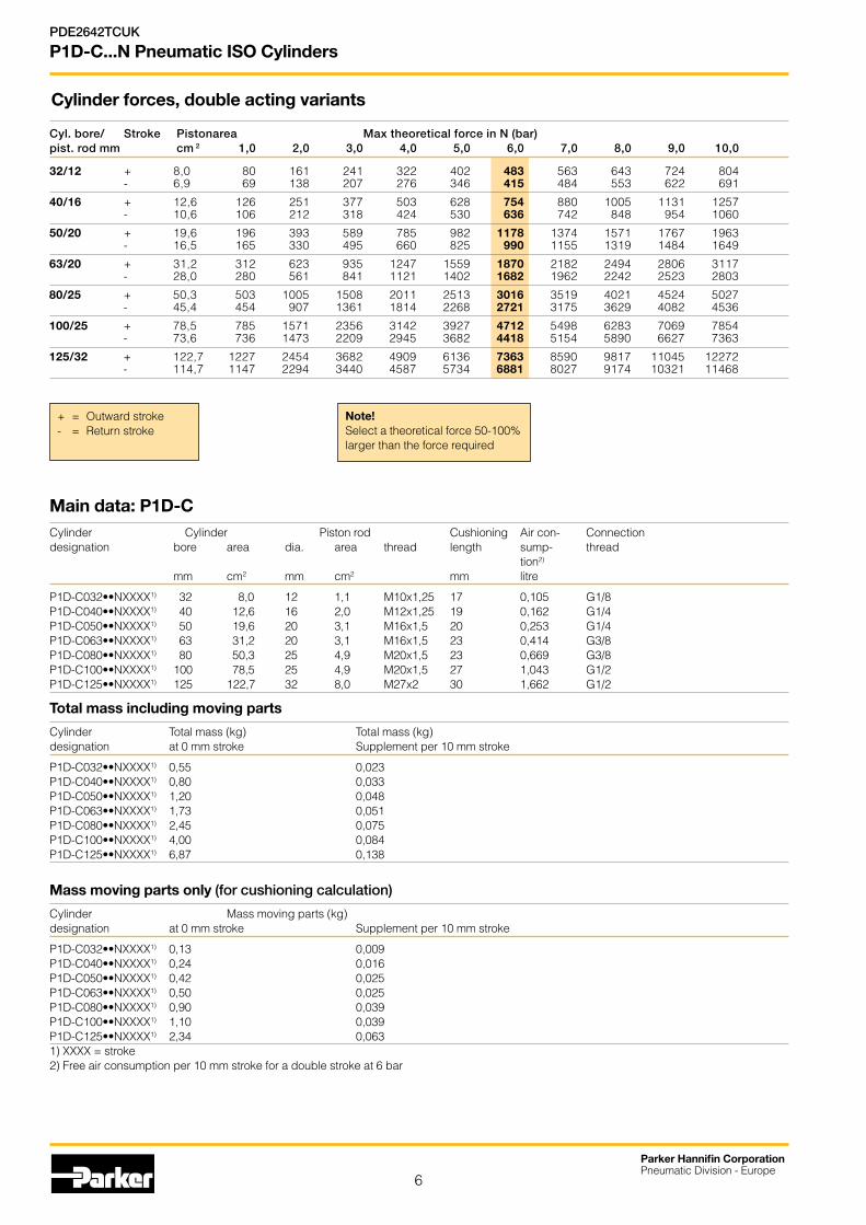
Main data: P1D-C Cylinder Cylinder Piston rod Cushioning Air con- Connection designation bore area dia. area thread length sump- thread tion2)
mm cm2 mm cm2 mm litre
P1D-C032••NXXXX1) 32 8,0 12 1,1 M10x1,25 17 0,105 G1/8P1D-C040••NXXXX1) 40 12,6 16 2,0 M12x1,25 19 0,162 G1/4P1D-C050••NXXXX1) 50 19,6 20 3,1 M16x1,5 20 0,253 G1/4P1D-C063••NXXXX1) 63 31,2 20 3,1 M16x1,5 23 0,414 G3/8P1D-C080••NXXXX1) 80 50,3 25 4,9 M20x1,5 23 0,669 G3/8P1D-C100••NXXXX1) 100 78,5 25 4,9 M20x1,5 27 1,043 G1/2P1D-C125••NXXXX1) 125 122,7 32 8,0 M27x2 30 1,662 G1/2
Total mass including moving parts
Cylinder Total mass (kg) Total mass (kg) designation at 0 mm stroke Supplement per 10 mm stroke
P1D-C032••NXXXX1) 0,55 0,023P1D-C040••NXXXX1) 0,80 0,033P1D-C050••NXXXX1) 1,20 0,048P1D-C063••NXXXX1) 1,73 0,051P1D-C080••NXXXX1) 2,45 0,075P1D-C100••NXXXX1) 4,00 0,084P1D-C125••NXXXX1) 6,87 0,138
Mass moving parts only (for cushioning calculation)
Cylinder Mass moving parts (kg) designation at 0 mm stroke Supplement per 10 mm stroke
P1D-C032••NXXXX1) 0,13 0,009P1D-C040••NXXXX1) 0,24 0,016P1D-C050••NXXXX1) 0,42 0,025P1D-C063••NXXXX1) 0,50 0,025P1D-C080••NXXXX1) 0,90 0,039P1D-C100••NXXXX1) 1,10 0,039P1D-C125••NXXXX1) 2,34 0,0631) XXXX = stroke 2) Free air consumption per 10 mm stroke for a double stroke at 6 bar
Cyl. bore/ Stroke Pistonarea Max theoretical force in N (bar) pist. rod mm cm 2 1,0 2,0 3,0 4,0 5,0 6,0 7,0 8,0 9,0 10,0
32/12 + 8,0 80 161 241 322 402 483 563 643 724 804 - 6,9 69 138 207 276 346 415 484 553 622 691
40/16 + 12,6 126 251 377 503 628 754 880 1005 1131 1257 - 10,6 106 212 318 424 530 636 742 848 954 1060
50/20 + 19,6 196 393 589 785 982 1178 1374 1571 1767 1963 - 16,5 165 330 495 660 825 990 1155 1319 1484 1649
63/20 + 31,2 312 623 935 1247 1559 1870 2182 2494 2806 3117 - 28,0 280 561 841 1121 1402 1682 1962 2242 2523 2803
80/25 + 50,3 503 1005 1508 2011 2513 3016 3519 4021 4524 5027 - 45,4 454 907 1361 1814 2268 2721 3175 3629 4082 4536
100/25 + 78,5 785 1571 2356 3142 3927 4712 5498 6283 7069 7854 - 73,6 736 1473 2209 2945 3682 4418 5154 5890 6627 7363
125/32 + 122,7 1227 2454 3682 4909 6136 7363 8590 9817 11045 12272 - 114,7 1147 2294 3440 4587 5734 6881 8027 9174 10321 11468
Note!Select a theoretical force 50-100% larger than the force required
+ = Outward stroke- = Return stroke
Cylinder forces, double acting variants

7
Parker Hannifin CorporationPneumatic Division - Europe
PDE2642TCUK
P1D-C...N Pneumatic ISO Cylinders
Operation data Working pressure Min 0,5 bar Max 10 barWorking temperature Min -20 °C Max +80 °C
Greased for life, does not normally need additional lubrication. If extra lubrication is given, this must always be continued.
Bores and strokesBores 32 - 125 mmStandard strokes 25 - 500 mm according to ISO 4393Max stroke P1D-C...N without sensor 2800 mm
Chemical resistanceTested for normally used industrial detergents both acid and alkaline.
Working medium, air quality Working medium Dry, filtered compressed air to ISO 8573-1 class 3.4.3.
Recommended air quality for cylinders
For best possible service life and trouble-free operation, ISO 8573-1 quality class 3.4.3 should be used. This means 5 µm filter (standard filter), dew point +3 ºC for indoor operation (a lower dew point should be selected for outdoor operation) and oil concentration 1.0 mg oil/m3, which is what a standard compressor with a standard filter gives.
ISO 8573-1 quality classes
Quality Pollution Water Oil class particle max max. press. max size concentration dew point concentration (µm) (mg/m³) (°C) (mg/m³)
1 0,1 0,1 -70 0,01 2 1 1 -40 0,1 3 5 5 -20 1,0 4 15 8 +3 5,0 5 40 10 +7 25 6 - - +10 -
Standard strokes Standard strokes for all P1D-C...N cylinders comply with ISO 4393 (with the exception of stroke 40 mm).Special strokes up to 2800 mm for P1D-C without sensors.
Order no Cylinder bore = Standard stroke (mm) = Stroke to special order XXXX = Stroke (mm) 25 40 50 80 100 125 160 200 250 320 400 500 600 700 800 2800
P1D-C withoutsensor
P1D-C032MSNXXXX 32P1D-C040MSNXXXX 40P1D-C050MSNXXXX 50P1D-C063MSNXXXX 63P1D-C080MSNXXXX 80P1D-C100MSNXXXX 100P1D-C125MSNXXXX 125
Important!If the cylinder is used in applications with significant lateral loads on the piston rod, an external guide must be used to achieve maximum service life. See the P1D-S series.

8
Parker Hannifin CorporationPneumatic Division - Europe
PDE2642TCUK
P1D-C...N Pneumatic ISO Cylinders
4,03,0
2,0
1,5
1,0
0,50,4
0,3
0,2
0,11 2 3 4 5 10 20 30 40 50 100 200 300 500 1000 2000
Ø32Ø40 Ø50
Ø63Ø80
Ø100Ø125
Speed [m/s]
Mass [kg]
Material specificationStandard design Body extrusion Natural colour, anodised aluminium End cover Black anodised aluminium End cover inserts POM End cover screws Zinc plated steel 8.8 Piston rod nut Zinc plated steelPiston rod Stainless steel, X 10 CrNiS 18 9Scraper ring PUR Piston rod bearing POM Piston POM Piston bearing POMPiston bolt Zinc plated steelPiston seal PUR O-rings Nitrile rubber, NBR End-of-stroke washers PUR Cushioning seals PUR Cushioning screws POM
Cushioning characteristicsThe diagram below is used for dimensioning of cylinders related to the cushioning capacity. The maximum cushioning capacity shown in the diagram assumes the following:
• Low load, i.e. low pressure drop across the piston• Equilibrium speed • Correctly adjusted cushioning screw • 6 bar at cylinder port
The load is the sum of internal and external friction, plus any gravitational forces. At high relative load (pressure drop exceeding 1 bar), we recommend that for any given speed, the mass should be reduced by a factor of 2.5, or for a given mass, the speed should be reduced by a factor of 1.5. This is in relation to the maximum performance given in the diagram
OptionsCylinders for dry rod operation
Seals/scraper ring FPM/HDPE
Alternative piston rod material
Piston rod material - Hard-chromium plated steel, Fe 490-2 FN - Acid-proof steel, X 5 CrNiMo 17 13 3 - Hard-chromium plated stainless steel,
X 10 CrNiS 18 9
Alternative end cover screws
End cover screws Stainless steel X 10 CrNiS 18 9

9
Parker Hannifin CorporationPneumatic Division - Europe
PDE2642TCUK
P1D-C...N Pneumatic ISO Cylinders
Guide for selecting suitable tubingThe selection of the correct size of tubing is often based on experience, with no great thought to optimizing energy efficiency and cylinder velocity. This is usually acceptable, but making a rough calculation can result in worthwhile economic gains.
The following is the basic principle:1. The primary line to the working valve could be over sized (this
does not cause any extra air consumption and consequently does not create any extra costs in operation).
2. The tubes between the valve and the cylinder should, however, be optimized according to the principle that an insufficient bore throttles the flow and thus limits the cylinder speed, while an oversized pipe creates a dead volume which increases the air consumption and filling time.
The chart below is intended to help when selecting the correct size of tube to use between the valve and the cylinder.
The following prerequisites apply:The cylinder load should be about 50% of the theoretical force (= normal load). A lower load gives a higher velocity and vice versa. The tube size is selected as a function of the cylinder bore, the desired cylinder velocity and the tube length between the valve and the cylinder.
If you want to use the capacity of the valve to its maximum, and obtain maximum speed, the tubing should be chosen so that they at least correspond with the equivalent restriction diameter (see description below), so that the tubing does not restrict the total flow. This means that a short tubing must have at least the equivalent restriction diameter. If the tubing is longer, choose it from the table below. Straight fittings should be chosen for highest flow rates. (Elbow and banjo fittings cause restriction.)
1) The “equivalent throttling bore“ is a long throttle (for example a tube) or a series of throttles (for example, through a valve) converted to a short throttle which gives a corresponding flow rate. This should not be confused with the “orifice“ which is sometimes specified for valves. The value for the orifice does not normally take account of the fact that the valve contains a number of throttles.
2) Qn is a measure of the valve flow capacity, with flow measured in litre per minute (l/min) at 6 bar(e) supply pressure and 1 bar pressure drop across the valve.
Cylinder Ø [mm]
Equivalent throttling bore 1) Tube ØOut./ØInt. [mm]
Length of tubing [m]Cylinder speed [m/s]0,2 0,5 0,8 1,1 1,4 0 1 2 3 4 5 6 7 8 9 10
1
2
3
4
5
6
7
8
9
10
11
Ø10Ø16Ø20Ø25Ø32Ø40Ø50
Ø63
Ø80
Ø100
Ø125
Ø160
Ø200
14/11–/12
–/13
–/14
–/15
–/16
12/10
10/8
8/6
6/45/34/2,7
200
400
800
1000
1200
14001600
1800200022002400
3000
4000
2800
3200340036003800
2600
4
3
2
1
Air flow Qn [Nl/min]

10
Parker Hannifin CorporationPneumatic Division - Europe
PDE2642TCUK
P1D-C...N Pneumatic ISO Cylinders
Example 1 : Which tube diameter should be used?A 50 mm bore cylinder is to be operated at 0.5 m/s. The tube length between the valve and cylinder is 2 m. In the diagram we follow the line from 50 mm bore to 0.5 m/s and get an “equivalent throttling bore“ of approximately 4 mm. We continue out to the right in the chart and intersect the line for a 2 m tube between the curves for 4 mm (6/4 tube) and 6 mm(8/6 tube). This means that a 6/4 tube throttles the velocity somewhat, while an 8/6 tube is a little too large. We select the 8/6 tube to obtain full cylinder velocity.
Example 2 : What cylinder velocity will be obtained?A 80 mm bore cylinder will be used, connected by 8 m 12/10 tube to a valve with Qn 1200 Nl/min. What cylinder velocity will we get? We refer to the diagram and follow the line from 8 mm tube length up to the curve for 12/10 tube. From there, we go horizontally to the curve for the Ø80 cylinder. We find that the velocity will be about 0.5 m/s.
Example 3 : What is the minimum inner diameter and maximum lenght of tube?For a application a 125 mm bore cylinder will be used. Maximum velocity of piston rod is 0.5 m/s. The cylinder will be controlled by a valve with Qn 3200 Nl/min. What diameter of tube can be used and what is maximum lenght of tube.We refer to the diagram. We start at the left side of the diagram cylinder Ø125. We follow the line until the intersection with the velocity line of 0.5 m/s. From here we draw a horizontal line in the diagram. This line shows us we need an equivalent throttling bore of approximately 10 mm. Following this line horizontally we cross a few intersections. These intersections shows us the minimum inner diameter (rightside diagram) in combination with the maximum length of tube (bottomside diagram).
For example: Intersection one: When a tube (14/11) will be used, the maximum length of tube is 0.7 meter. Intersection two: When a tube (—/13) will be used, the maximum length of tube is 3.7 meter. Intersection three: When a tube (—/14) will be used, the maximum length of tube is 6 meter.
Example 4 : Determining tube size and cylinder velocity with a particular cylinder and valve?For an application using a 40 mm bore cylinder with a valve with Qn=800 Nl/min. The distance between the cylinder and valve has been set to 5 m.Tube dimension: What tube bore should be selected to obtain the maximum cylinder velocity? Start at pipe length 5 m, follow the line up to the intersection with 800 Nl/min. Select the next largest tube diameter, in this case Ø10/8 mm.Cylinder velocity: What maximum cylinder velocity will be obtained? Follow the line for 800 Nl/min to the left until it intersects with the line for the Ø40 mm cylinder. In this example, the speed is just above 1.1 m/s.
Valve series with respective flows in Nl/minute
Valve series Qn in Nl/Min
Interface PS1 120
Moduflex Size 1 - Double 4/2 single solenoid 165
Adex A05 173
Isys Micro - Single 5/3 APB 228
Moduflex Size 1 - Single or Double 3/2 235
Isys Micro - Double 3/2 276
Isys Micro - Single 5/2 282
Moduflex Size 1 - Single 4/2 310
ISOMAX DX02 378
ISYS ISO HB 390
Moduflex Size 2 - Single or Double 3/2 440
PVL-B stackable inline valve 540
Adex A12 560
ISOMAX DX01 588
Viking Xtrem P2LAX - G1/8" 660
Moduflex Size 2 - Single 4/2 800
ISYS ISO HA 918
ISOMAX DX1 & DX Rail 1032
PVL-C stackable inline valve 1100
ISYS ISO H1 1248
Viking Xtrem P2LBX - G1/4" 1290
ISOMAX DX2 & DX Rail 2298
Viking Xtrem P2LCX - G3/8" 2460
ISYS ISO H2 2520
Viking Xtrem P2LDX - G1/2" 2658
ISOMAX DX3 & DX Rail 3840
ISYS ISO H3 5022

11
Parker Hannifin CorporationPneumatic Division - Europe
PDE2642TCUK
P1D-C...N Pneumatic ISO Cylinders
Dimensions (mm)Cylinder bore A AM B B1 BA BG C D D4 E EE G KK L2 mm mm mm mm mm mm mm mm mm mm mm mm mm mm
32 15 22 30 8 30 16 5,2 12 45,0 50,0 G1/8 28,5 M10x1,25 16,0 40 15 24 35 8 35 16 5,2 16 52,0 57,4 G1/4 33,0 M12x1,25 19,0 50 18,5 32 40 10 40 16 6,7 20 60,7 69,4 G1/4 33,5 M16x1,5 24,0 63 18,5 32 45 10 45 16 6,7 20 71,5 82,4 G3/8 39,5 M16x1,5 24,0 80 21,5 40 45 11 45 17 7,8 25 86,7 99,4 G3/8 39,5 M20x1,5 30,0100 21,5 40 55 11 55 17 7,8 25 106,7 116,0 G1/2 44,5 M20x1,5 32,4125 24 54 60 13 60 20 9,3 32 134,0 139,0 G1/2 51,0 M27x2 45,0
Cylinder bore L8 L9 L12 PL PP R RT SS SW TT VA VD WH WL WT mm mm mm mm mm mm mm mm mm mm mm mm mm mm 32 94 146 6,0 13,0 21,8 32,5 M6 4,0 10 4,5 3,5 4,5 26 21 M8x1 40 105 165 6,5 14,0 21,9 38,0 M6 8,0 13 5,5 3,5 4,5 30 23 M10x1,25 50 106 180 8,0 14,0 23,0 46,5 M8 4,0 17 7,5 3,5 5,0 37 31 M14x1,5 63 121 195 8,0 16,4 27,4 56,5 M8 6,5 17 11,0 3,5 5,0 37 31 M14x1,5 80 128 220 10,0 16,0 30,5 72,0 M10 0 22 15,0 3,5 4,0 46 39 M18x1,5100 138 240 14,0 18,0 35,8 89,0 M10 0 22 20,0 3,5 4,0 51 39 M18x1,5125 160 290 18,0 28,0 40,5 110,0 M12 0 27 17,5 5,5 6,0 65 53 M24x2S=Stroke
Tolerances (mm)Cylinder bore B BA L8 L9 R Stroke tolerance Stroke tolerancemm mm mm mm up to stroke 500 mm for stroke over 500 mm
32 d11 d11 ±0,4 ±2 ±0,5 +0,3/+2,0 +0,3/+3,0 40 d11 d11 ±0,7 ±2 ±0,5 +0,3/+2,0 +0,3/+3,0 50 d11 d11 ±0,7 ±2 ±0,6 +0,3/+2,0 +0,3/+3,0 63 d11 d11 ±0,8 ±2 ±0,7 +0,3/+2,0 +0,3/+3,0 80 d11 d11 ±0,8 ±3 ±0,7 +0,3/+2,0 +0,3/+3,0100 d11 d11 ±1,0 ±3 ±0,7 +0,3/+2,0 +0,3/+3,0125 d11 d11 ±1,0 ±3 ±1,1 +0,3/+2,0 +0,3/+3,0
Internal piston rod thread
WT
WH
WHWL
WH + S
L 9 + 2 x S
BG
E2
C
AM
ØB
ØD
KK
VDG
WHL2
L12
D 4
PPPL
SS
TT Ø
BA
VAG
L8 + S
RT
R
E
DIN 439B
SW
EE
ØA
B1
P1D-C...N Without sensor Sealing plug as accessory
WT
WH
WHWL
WH + S
L 9 + 2 x S
BG
E2
C
AM
ØB
ØD
KK
VDG
WHL2
L12
D 4
PPPL
SS
TT Ø
BA
VAG
L8 + S
RT
R
E
DIN 439B
SW
EE
ØA
B1
WT
WH
WHWL
WH + S
L 9 + 2 x S
BG
E2
C
AM
ØB
ØD
KK
VDG
WHL2
L12
D 4
PPPL
SS
TT Ø
BA
VAG
L8 + S
RT
R
E
DIN 439B
SW
EE
ØA
B1

12
Parker Hannifin CorporationPneumatic Division - Europe
PDE2642TCUK
P1D-C...N Pneumatic ISO Cylinders
P1D-C...N without sensor
Cyl. bore Stroke Order codemm mm
32 25 P1D-C032MSN0025Conn. G1/8 40 P1D-C032MSN0040 50 P1D-C032MSN0050 80 P1D-C032MSN0080 100 P1D-C032MSN0100 125 P1D-C032MSN0125 160 P1D-C032MSN0160 200 P1D-C032MSN0200 250 P1D-C032MSN0250 320 P1D-C032MSN0320 400 P1D-C032MSN0400 500 P1D-C032MSN0500
40 25 P1D-C040MSN0025Conn. G1/4 40 P1D-C040MSN0040 50 P1D-C040MSN0050 80 P1D-C040MSN0080 100 P1D-C040MSN0100 125 P1D-C040MSN0125 160 P1D-C040MSN0160 200 P1D-C040MSN0200 250 P1D-C040MSN0250 320 P1D-C040MSN0320 400 P1D-C040MSN0400 500 P1D-C040MSN0500
50 25 P1D-C050MSN0025Conn. G1/4 40 P1D-C050MSN0040 50 P1D-C050MSN0050 80 P1D-C050MSN0080 100 P1D-C050MSN0100 125 P1D-C050MSN0125 160 P1D-C050MSN0160 200 P1D-C050MSN0200 250 P1D-C050MSN0250 320 P1D-C050MSN0320 400 P1D-C050MSN0400 500 P1D-C050MSN0500
63 25 P1D-C063MSN0025Conn. G3/8 40 P1D-C063MSN0040 50 P1D-C063MSN0050 80 P1D-C063MSN0080 100 P1D-C063MSN0100 125 P1D-C063MSN0125 160 P1D-C063MSN0160 200 P1D-C063MSN0200 250 P1D-C063MSN0250 320 P1D-C063MSN0320 400 P1D-C063MSN0400 500 P1D-C063MSN0500
P1D-C...N without sensorThe order numbers on this page refer to P1D-C without sensor. The cylinders can be ordered as a complete unit with fittings, piston rod and cylinder mountings, speed controls etc. for efficient logistics. Please refer to the order code key to select cylinders with factory-fitted accessories.
Cyl. bore Stroke Order codemm mm
80 25 P1D-S080MSN0025Conn. G3/8 40 P1D-C080MSN0040 50 P1D-C080MSN0050 80 P1D-C080MSN0080 100 P1D-C080MSN0100 125 P1D-C080MSN0125 160 P1D-C080MSN0160 200 P1D-C080MSN0200 250 P1D-C080MSN0250 320 P1D-C080MSN0320 400 P1D-C080MSN0400 500 P1D-C080MSN0500
100 25 P1D-C100MSN0025Conn. G1/2 40 P1D-C100MSN0040 50 P1D-C100MSN0050 80 P1D-C100MSN0080 100 P1D-C100MSN0100 125 P1D-C100MSN0125 160 P1D-C100MSN0160 200 P1D-C100MSN0200 250 P1D-C100MSN0250 320 P1D-C100MSN0320 400 P1D-C100MSN0400 500 P1D-C100MSN0500
125 25 P1D-C125MSN0025Conn. G1/2 40 P1D-C125MSN0040 50 P1D-C125MSN0050 80 P1D-C125MSN0080 100 P1D-C125MSN0100 125 P1D-C125MSN0125 160 P1D-C125MSN0160 200 P1D-C125MSN0200 250 P1D-C125MSN0250 320 P1D-C125MSN0320 400 P1D-C125MSN0400 500 P1D-C125MSN0500

13
Parker Hannifin CorporationPneumatic Division - Europe
PDE2642TCUK
P1D-C...N Pneumatic ISO Cylinders
Flange trunnion 11 Center Trunnion 12 Swivel rod eye AP6 13 Clevis AP2 14 Flexo coupling PM5 15 MT5/MT6 MT4
Ø 32 P1D-4KMYF Factory fitted P1C-4KRS P1C-4KRC P1C-4KRF Ø 40 P1D-4LMYF Factory fitted P1C-4LRS P1C-4LRC P1C-4LRFØ 50 P1D-4MMYF Factory fitted P1C-4MRS P1C-4MRC P1C-4MRFØ 63 P1D-4NMYF Factory fitted P1C-4MRS P1C-4MRC P1C-4MRFØ 80 P1D-4PMYF Factory fitted P1C-4PRS P1C-4PRC P1C-4PRFØ 100 P1D-4QMYF Factory fitted P1C-4PRS P1C-4PRC P1C-4PRFØ 125 Factory fitted P1C-4RRS P1C-4RRC P1C-4RRF
Clevis bracket MP4 6 Clevis bracket AB6 7 Pivot bracket with 8 3 and 4 positions Pivot brackets AT4 10
swivel bearing CS7 flange JP1 for MT* trunnion
Ø 32 P1C-4KME P1C-4KMCA P1C-4KMA P1E-6KB0 9301054261 Ø 40 P1C-4LME P1C-4LMCA P1C-4LMA P1E-6LB0 9301054262Ø 50 P1C-4MME P1C-4MMCA P1C-4MMA P1E-6MB0 9301054262Ø 63 P1C-4NME P1C-4NMCA P1C-4NMA P1E-6NB0 9301054264Ø 80 P1C-4PME P1C-4PMCA P1C-4PMA P1E-6PB0 9301054264Ø 100 P1C-4QME P1C-4QMCA P1C-4QMA P1E-6QB0 9301054266Ø 125 P1C-4RME P1C-4RMCA P1C-4RMA 9301054266
Flange MF1/MF2 1 Foot brackets MS1 2 Pivot bracket with 3 Swivel eye bracket 4 Clevis bracket MP2 5
rigid bearing AB7 MP6
Ø 32 P1C-4KMB P1C-4KMF P1C-4KMD P1C-4KMSA P1C-4KMT Ø 40 P1C-4LMB P1C-4LMF P1C-4LMD P1C-4LMSA P1C-4LMTØ 50 P1C-4MMB P1C-4MMF P1C-4MMD P1C-4MMSA P1C-4MMTØ 63 P1C-4NMB P1C-4NMF P1C-4NMD P1C-4NMSA P1C-4NMTØ 80 P1C-4PMB P1C-4PMF P1C-4PMD P1C-4PMSA P1C-4PMTØ 100 P1C-4QMB P1C-4QMF P1C-4QMD P1C-4QMSA P1C-4QMTØ 125 P1C-4RMB P1C-4RMF P1C-4RMD P1C-4RMSA P1C-4RMT
1 15
1413
11
10
8
7
6
54
3
2
11
10
7
54
21
10
Zinc-plated steel nut MR9
Ø 32 P14-4KRPZØ 40 P14-4LRPZØ 50 P14-4MRPZØ 63 P14-4MRPZØ 80 P14-4PRPZØ 100 P14-4PRPZØ 125 P14-4RRPZ
12
Mountings

14
Parker Hannifin CorporationPneumatic Division - Europe
PDE2642TCUK
P1D-C...N Pneumatic ISO Cylinders Cylinder mountings
Flange MF1/MF2 Intended for fixed mounting of cylinder. Flange can be fitted to front or rear end cover of cylinder. Material: Flange: Surface-treated steel Mounting screws acc. to DIN 6912: Zinc-plated steel 8.8 Supplied complete with mounting screws for attachment to cylinder.
Cyl. d1 FB TG1 E R MF TF UF l1 W ZF ZB bore H11 H13 JS14 JS14 JS14 -0,5mm mm mm mm mm mm mm mm mm mm mm mm mm
32 30 7 32,5 45 32 10 64 80 5,0 16 130 123,5 40 35 9 38,0 52 36 10 72 90 5,0 20 145 138,5 50 40 9 46,5 65 45 12 90 110 6,5 25 155 146,5 63 45 9 56,5 75 50 12 100 120 6,5 25 170 161,5 80 45 12 72,0 95 63 16 126 150 8,0 30 190 177,5100 55 14 89,0 115 75 16 150 170 8,0 35 205 192,5125 60 16 110,0 140 90 20 180 205 10,5 45 245 230,5S = Stroke length
Foot brackets MS1 Intended for fixed mounting of cylinder. Foot bracket can be fitted to front and rear end covers of cylinder. Material: Foot bracket: Surface-treated steel Mounting screws acc. to DIN 912: Zinc-plated steel 8.8 Supplied in pairs with mounting screws for attachment to cylinder .
Cyl. AB TG1 E TR AO AU AH l7 AT l9 SA bore H14 JS14 JS15 JS14mm mm mm mm mm mm mm mm mm mm mm mm
32 7 32,5 45 32 10 24 32 30 4,5 17,0 142 40 9 38,0 52 36 8 28 36 30 4,5 18,5 161 50 9 46,5 65 45 13 32 45 36 5,5 25,0 170 63 9 56,5 75 50 13 32 50 35 5,5 27,5 185 80 12 72,0 95 63 14 41 63 49 6,5 40,5 210100 14 89,0 115 75 15 41 71 54 6,5 43,5 220125 16 110,0 140 90 22 45 90 71 8,0 60,0 250
S = Stroke length
Pivot bracket with Intended for flexible mounting of cylinder. The rigid bearing AB7 pivot bracket can be combined with clevis bracket MP2.
Material: Pivot bracket: Surface-treated aluminium, black Bearing: Sintered oil-bronze bushing
Cyl. CK S5 K1 K2 G1 G2 EM G3 CA H6 R1 bore H9 H13 JS14 JS14 JS14 JS15mm mm mm mm mm mm mm mm mm mm mm mm
32 10 6,6 38 51 21 18 25,5 31 32 8 10,0 40 12 6,6 41 54 24 22 27,0 35 36 10 11,0 50 12 9,0 50 65 33 30 31,0 45 45 12 13,0 63 16 9,0 52 67 37 35 39,0 50 50 12 15,0 80 16 11,0 66 86 47 40 49,0 60 63 14 15,0100 20 11,0 76 96 55 50 59,0 70 71 15 19,0125 25 14,0 94 124 70 60 69,0 90 90 20 22,5
32 0,23 P1C-4KMB 40 0,28 P1C-4LMB 50 0,53 P1C-4MMB 63 0,71 P1C-4NMB 80 1,59 P1C-4PMB100 2,19 P1C-4QMB125 3,78 P1C-4RMB
ØF
B
R
UF
Ød1 TF
E
TG1
ZB+S
MFMF
W
ZF+S
I1
5
G
ØC
K
CA
G2
G3
1R1
H6
KK12
SØ
EM
SA+S
ØAB
AU AO
AT
E
TG1
9 IAH
TR7
I
32 0,06** P1C-4KMF 40 0,08** P1C-4LMF 50 0,16** P1C-4MMF 63 0,25** P1C-4NMF 80 0,50** P1C-4PMF100 0,85** P1C-4QMF125 1,48** P1C-4RMF
** Weight per item
32 0,06 P1C-4KMD 40 0,08 P1C-4LMD 50 0,15 P1C-4MMD 63 0,20 P1C-4NMD 80 0,33 P1C-4PMD100 0,49 P1C-4QMD125 1,02 P1C-4RMD
Type Description Cyl. bore Weight Order code Ø mm kg
For mounting screwsin stainless steel seepage 21

15
Parker Hannifin CorporationPneumatic Division - Europe
PDE2642TCUK
P1D-C...N Pneumatic ISO Cylinders Cylinder mountings
Swivel eye bracket MP6 Intended for use together with clevis bracket GA Material: Bracket: Surface-treated aluminium, black Swivel bearing acc. to DIN 648K: Hardened steel Supplied complete with mounting screws for attachment to cylinder.
Mounting screws acc. to DIN 912: Zinc-plated steel 8.8
Cyl. E B1 B2 EN R1 R2 FL l2 L CN XD Z bore H7 mm mm mm mm mm mm mm mm mm mm mm mm
32 45 10,5 - 14 16 - 22 5,5 12 10 142 4° 40 52 12,0 - 16 18 - 25 5,5 15 12 160 4° 50 65 15,0 51 21 21 19 27 6,5 15 16 170 4° 63 75 15,0 - 21 23 - 32 6,5 20 16 190 4° 80 95 18,0 - 25 29 - 36 10,0 20 20 210 4°100 115 18,0 - 25 31 - 41 10,0 25 20 230 4°125 140 25,0 - 37 40 - 50 10,0 30 30 275 4°S = Stroke length
Clevis bracket MP2 Intended for flexible mounting of cylinder. Clevis bracket MP2 can be combined with clevis bracket MP4. Material: Clevis bracket: Surface-treated aluminium, black Pin: Surface hardened steel Circlips according to DIN 471: Spring steel Mounting screws acc. to DIN 912: Zinc-plated steel 8.8 Supplied complete with mounting screws for attachment to cylinder .
Cyl. C E UB CB FL L l2 CD MR XD bore h14 H14 ±0,2 H9 mm mm mm mm mm mm mm mm mm mm mm
32 53 45 45 26 22 13 5,5 10 10 142 40 60 52 52 28 25 16 5,5 12 12 160 50 68 65 60 32 27 16 6,5 12 12 170 63 78 75 70 40 32 21 6,5 16 16 190 80 98 95 90 50 36 22 10,0 16 16 210100 118 115 110 60 41 27 10,0 20 20 230125 139 140 130 70 50 30 10,0 25 25 275S = Stroke length
32 0,08 P1C-4KMSA 40 0,11 P1C-4LMSA 50 0,20 P1C-4MMSA 63 0,27 P1C-4NMSA 80 0,52 P1C-4PMSA100 0,72 P1C-4QMSA125 1,53 P1C-4RMSA
32 0,08 P1C-4KMT 40 0,11 P1C-4LMT 50 0,14 P1C-4MMT 63 0,29 P1C-4NMT 80 0,36 P1C-4PMT100 0,64 P1C-4QMT125 1,17 P1C-4RMT
UB
CB
E
XD+S
MR
I
FL
L
2
C
XD+S
ØCN
R1
L
R2
B
B1
2
EN
L2FL
ZZ
Type Description Cyl. bore Weight Order code Ø mm kg
For mounting screwsin stainless steel seepage 21

16
Parker Hannifin CorporationPneumatic Division - Europe
PDE2642TCUK
P1D-C...N Pneumatic ISO Cylinders Cylinder mountings
Clevis bracket MP4 Intended for flexible mounting of cylinder. Clevis bracket MP4 can be combined with clevis bracket MP2. Material: Clevis bracket: Surface-treated aluminium, black Mounting screws acc. to DIN 912: Zinc-plated steel 8.8 Supplied complete with mounting screws for attachment to cylinder .
Cyl. E EW FL L l2 CD MR XD bore ±0,2 H9mm mm mm mm mm mm mm mm mm
32 45 26 22 13 5,5 10 10 142 40 52 28 25 16 5,5 12 12 160 50 65 32 27 16 6,5 12 12 170 63 75 40 32 21 6,5 16 16 190 80 95 50 36 22 10,0 16 16 210100 115 60 41 27 10,0 20 20 230125 140 70 50 30 10,0 25 25 275S = Stroke length
Clevis bracket AB6 Intended for flexible mounting of cylinder. Clevis bracket GA can be combined with pivot bracket with swivel bearing, swivel eye bracket and swivel rod eye. Material: Clevis bracket: Surface-treated aluminium Pin: Surface hardened steel Locking pin: Spring steel Circlips according to DIN 471: Spring steel Mounting screws acc. to DIN 912: Zinc-plated steel 8.8 Supplied complete with mounting screws for attachment to cylinder .
Cyl. C E B2 B1 T B3 R2 L1 FL l2 L CN R1 XD bore d12 H14 ±0,2 F7mm mm mm mm mm mm mm mm mm mm mm mm mm mm mm
32 41 45 34 14 3 3,3 17 11,5 22 5,5 12 10 11 142 40 48 52 40 16 4 4,3 20 12,0 25 5,5 15 12 13 160 50 54 65 45 21 4 4,3 22 14,0 27 6,5 17 16 18 170 63 60 75 51 21 4 4,3 25 14,0 32 6,5 20 16 18 190 80 75 95 65 25 4 4,3 30 16,0 36 10,0 20 20 22 210100 85 115 75 25 4 4,3 32 16,0 41 10,0 25 20 22 230125 110 140 97 37 6 6,3 42 24,0 50 10,0 30 30 30 275S = Stroke length
32 0,09 P1C-4KMCA 40 0,13 P1C-4LMCA 50 0,17 P1C-4MMCA 63 0,36 P1C-4NMCA 80 0,58 P1C-4PMCA100 0,89 P1C-4QMCA125 1,75 P1C-4RMCA
EW
E
XD+S
CD
MR
I
FL
L
2
32 0,09 P1C-4KME 40 0,13 P1C-4LME 50 0,17 P1C-4MME 63 0,36 P1C-4NME 80 0,46 P1C-4PME100 0,83 P1C-4QME125 1,53 P1C-4RME
XD+S
CN
R1
L
L
R2
B
B
E
1
2B
3
T1
L2FL
C
Type Description Cyl. bore Weight Order code Ø mm kg
For mounting screwsin stainless steel seepage 21

17
Parker Hannifin CorporationPneumatic Division - Europe
PDE2642TCUK
P1D-C...N Pneumatic ISO Cylinders Cylinder mountings
Pivot bracket with Intended for use together with clevis bracket GA.swivel bearing CS7
Material: Pivot bracket: Surface-treated steel, black Swivel bearing acc. to DIN 648K: Hardened steel
Cyl. CN S5 K1 K2 EU G1 G2 EN G3 CH H6 ER Z bore H7 H13 JS14 JS14 JS14 JS15mm mm mm mm mm mm mm mm mm mm mm mm mm
32 10 6,6 38 51 10,5 21 18 14 31 32 10 16 4° 40 12 6,6 41 54 12,0 24 22 16 35 36 10 18 4° 50 16 9,0 50 65 15,0 33 30 21 45 45 12 21 4° 63 16 9,0 52 67 15,0 37 35 21 50 50 12 23 4° 80 20 11,0 66 86 18,0 47 40 25 60 63 14 28 4°100 20 11,0 76 96 18,0 55 50 25 70 71 15 30 4°125 30 14,0 94 124 25,0 70 60 37 90 90 20 40 4°
3 and 4 positions flange JP1 Mounting kit for back to back mounted cylinders, 3 and 4 position cylinders. Material: Mounting: Aluminium Mounting screws acc. to DIN 912: Zinc-plated steel 8.8 Material:
Pivot bracket: Surface-treated steel, black Swivel bearing acc. to DIN 648K: Hardened steel
Cyl. E TG ØFB MF A ØBA bore mm mm mm mm mm mm mm
32 50 32,5 6,5 5 16 30 40 60 38,0 6,5 5 16 35 50 66 46,5 8,5 6 20 40 63 80 56,5 8,5 6 20 45 80 100 72,0 10,5 8 25 45100 118 89,0 10,5 8 25 55
Pivot brackets AT4 Intended for use together with centre trunnion MT4.for MT* Trunnion Material: Pivot bracket: Surface-treated aluminium Bearing acc. to DIN 1850 C: Sintered oil-bronze bushing Supplied in pairs.
Cyl. B1 B2 A C d1 d2 H1 H2 fx45° bore H13 minmm mm mm mm mm mm mm mm mm mm
32 46 18,0 32 10,5 12 6,6 30 15 1,0 40 55 21,0 36 12,0 16 9,0 36 18 1,6 50 55 21,0 36 12,0 16 9,0 36 18 1,6 63 65 23,0 42 13,0 20 11,0 40 20 1,6 80 65 23,0 42 13,0 20 11,0 40 20 1,6100 75 28,5 50 16,0 25 14,0 50 25 2,0125 75 28,5 50 16,0 25 14,0 50 25 2,0
5
G
ØC
N
CH
G2
G3
1ER
H6
KK12
SØ
EU
ZZ
EN
E
TG
ØFB
ETG
A
MF
ØBA
32 0,04* 9301054261 40 0,07* 9301054262 50 0,07* 9301054262 63 0,12* 9301054264 80 0,12* 9301054264100 0,21* 9301054266125 0,21* 9301054266
* Weight per item.
32 0,18 P1C-4KMA 40 0,25 P1C-4LMA 50 0,47 P1C-4MMA 63 0,57 P1C-4NMA 80 1,05 P1C-4PMA100 1,42 P1C-4QMA125 3,10 P1C-4RMA
32 0,060 P1E-6KB0 40 0,078 P1E-6LB0 50 0,162 P1E-6MB0 63 0,194 P1E-6NB0 80 0,450 P1E-6PB0100 0,672 P1E-6QB0
C
B2
fx45°
H2
Ød1
H1
AB1
Ød2
Type Description Cyl. bore Weight Order code Ø mm kg
For mounting screwsin stainless steel seepage 21

18
Parker Hannifin CorporationPneumatic Division - Europe
PDE2642TCUK
P1D-C...N Pneumatic ISO Cylinders Cylinder mountings
32 0,036 See order 40 0,082 key on 50 0,082 pages 63 0,100 28-29 80 0,110
TL
UW
TM
TD
TL
R
XVstd
XVmin
XVmax
32 0,17 P1D-4KMYF 40 0,43 P1D-4LMYF 50 0,55 P1D-4MMYF 63 1,10 P1D-4NMYF 80 1,66 P1D-4PMYF100 3,00 P1D-4QMYF
TL
UW
TM
TD
TL
R
XV1
L1LL
XV2
L1LL
Type Description Cyl. bore Trunnion weight Order code Ø mm kg
Clean design centre trunnion Intended for articulated mounting of P1D-C cylinders. for P1D-C Ultra Clean only The trunnion is factory-fitted in the centre of the cylinder or at an optional location specified by the XV-measure – see
the order code key. Combined with pivot bracket for MT4. Max stroke length 700 mm. Longer stroke length on request. Material: Trunnion: stainless steel
Trunnion centred The centre trunnion for P1D-C is ordered with letter D in
position 17 (no dimension specified in positions 18-20). See the order code key at pages 28-29.
Trunnion with optional locationThe centre trunnion for P1D-C is ordered with letter G in position 17 and desired XV-measure (3-digit measure in mm) in positions 18-20. See the order code key at page 24-25.
Cyl. TM TL TD R UW X1* XVmin X2 Stroke bore h14 h14 e9 minmm mm mm mm mm mm mm mm mm mm
32 50 12 12 1,0 52 73,0 69,5 76,0 0 40 63 16 16 1,6 59 82,5 78,0 86,5 0 50 75 16 16 1,6 71 90,0 85,5 94,5 0 63 90 20 20 1,6 84 97,5 103,5 91,0 15 80 110 20 20 1,6 105 110,0 112,5 107,0 10
XVstd = X1 + Stroke length/2, XVmax = X2 + Stroke length
Flange trunnion Intended for articulated mounting of cylinder. This trunnion MT5/MT6 can be flange mounted on the front or rear end cover of all P1D cylinders. At your choice, you can order a complete cylinder with factory-fitted flange mounted trunnion – see the order code key at pages 28 and 29. Individual trunnions have order code as shown to the right. Material: Trunnion: zinc plated steel Mounting screws acc. to DIN 912: Zinc-plated steel 8.8 Delivered complete with mounting screws for attachment to the cylinder
Cyl. TM TL TD R UW L1 XV1 X Ybore h14 h14 e9mm mm mm mm mm mm mm mm mm mm
32 50 12 12 1,0 46 14 19,5 126,5 11 40 63 16 16 1,6 59 19 21,0 144,0 14 50 75 16 16 1,6 69 19 28,0 152,0 20 63 90 20 20 1,6 84 24 25,5 169,5 20 80 110 20 20 1,6 102 24 34,5 185,5 26100 132 25 25 2,0 125 29 37,0 203,0 31
For mounting screwsin stainless steel seepage 21

19
Parker Hannifin CorporationPneumatic Division - Europe
PDE2642TCUK
P1D-C...N Pneumatic ISO Cylinders Piston rod mountings
Swivel rod eye AP6 Swivel rod eye for articulated mounting of cylinder. Swivel rod eye can be combined with clevis bracket GA. Maintenance-free. Material: Swivel rod eye: Zinc-plated steel Swivel bearing according to DIN 648K: Hardened steel
Stainless steel swivel rod Stainless-steel swivel rod eye for articulated mounting eye AP6 of cylinder. Swivel rod eye can be combined with clevis bracket GA. Maintenance-free. Material: Swivel rod eye: Stainless steel Swivel bearing according to DIN 648K: Stainless steel
According to ISO 8139
Cyl. A B B CE CN EN ER KK LE N O Z bore min max H9 h12 minmm mm mm mm mm mm mm mm mm mm mm
32 20 48,0 55 43 10 14 14 M10x1,25 15 17 10,5 12° 40 22 56,0 62 50 12 16 16 M12x1,25 17 19 12,0 12° 50 28 72,0 80 64 16 21 21 M16x1,5 22 22 15,0 15° 63 28 72,0 80 64 16 21 21 M16x1,5 22 22 15,0 15° 80 33 87,0 97 77 20 25 25 M20x1,5 26 32 18,0 15°100 33 87,0 97 77 20 25 25 M20x1,5 26 32 18,0 15°125 51 123,5 137 110 30 37 35 M27x2 36 41 25,0 15°
Clevis AP2 Clevis for articulated mounting of cylinder. Material: Clevis, clip: Galvanized steel Pin: Hardened steel
Stainless steel clevis AP2 Stainless-steel clevis for articulated mounting of cylinder. Material: Clevis: Stainless steel Pin: Stainless steel Circlips according to DIN 471: Stainless steel
According to ISO 8140
Cyl. A B B CE CK CL CM ER KK LE O bore min max h11/E9mm mm mm mm mm mm mm mm mm mm mm
32 20 45,0 52 40 10 20 10 16 M10x1,25 20 28,0 40 24 54,0 60 48 12 24 12 19 M12x1,25 24 32,0 50 32 72,0 80 64 16 32 16 25 M16x1,5 32 41,5 63 32 72,0 80 64 16 32 16 25 M16x1,5 32 41,5 80 40 90,0 100 80 20 40 20 32 M20x1,5 40 50,0100 40 90,0 100 80 20 40 20 32 M20x1,5 40 50,0125 56 123,5 137 110 30 55 30 45 M27x2 54 72,0
CK
B
ER
CELEA
CL
CM O
KK
32 0,08 P1C-4KRS 40 0,12 P1C-4LRS 50 0,25 P1C-4MRS 63 0,25 P1C-4MRS 80 0,46 P1C-4PRS100 0,46 P1C-4PRS125 1,28 P1C-4RRS
32 0,08 P1S-4JRT 40 0,12 P1S-4LRT 50 0,25 P1S-4MRT 63 0,25 P1S-4MRT 80 0,46 P1S-4PRT100 0,46 P1S-4PRT125 1,28 P1S-4RRT
32 0,09 P1C-4KRC 40 0,15 P1C-4LRC 50 0,35 P1C-4MRC 63 0,35 P1C-4MRC 80 0,75 P1C-4PRC100 0,75 P1C-4PRC125 2,10 P1C-4RRC
32 0,09 P1S-4JRD 40 0,15 P1S-4LRD 50 0,35 P1S-4MRD 63 0,35 P1S-4MRD 80 0,75 P1S-4PRD100 0,75 P1S-4PRD125 2,10 P1S-4RRD
CN
B
N
Z
ACE
LE
O
KK
EN
ER
Z
Type Description Cyl. bore Weight Order code Ø mm kg

20
Parker Hannifin CorporationPneumatic Division - Europe
PDE2642TCUK
P1D-C...N Pneumatic ISO Cylinders Piston rod mountings
Flexo coupling PM5 Flexo coupling for articulated mounting of piston rod. Flexo fitting is intended to take up axial angle errors within a range of ±4°. Material: Flexo coupling, nut: Zinc-plated steel Socket: Hardened steel Supplied complete with galvanized adjustment nut.
A
C B
Type Description Cyl. bore Weight Order code Ø mm kg
Cyl. KK B C D E OF SW1 SW2 SW3 SW4 SW5 bore mm mm mm mm mm mm mm mm mm mm mm mm
32 M10x1.25 20 23 73 31 21 12 30 30 19 17 40 M12x1.25 24 23 77 31 21 12 30 30 19 19 50 M16x1.5 32 32 108 45 33.5 19 41 41 30 24 63 M16x1.5 32 32 108 45 33.5 19 41 41 30 24 80 M20x1.5 40 42 122 56 33.5 19 41 41 30 30100 M20x1.5 40 42 122 56 33.5 19 41 41 30 30125 M27x2 54 48 147 51 39 24 55 55 32 41
Type Description Cyl. bore Weight Order code Ø mm kg
Nut MR9 * Intended for fixed mounting of accessories to the piston rod. Material: Zinc-plated steel
Stainless steel nut MR9 * Intended for fixed mounting of accessories to the piston rod.All P1D..N cylinders are delivered with a stainless steel piston rod nut Material: Stainless steel A2
Acid-proof nut MR9 * Intended for fixed mounting of accessories to the piston rod. Material: Acid-proof steel A4
According to DIN 439 B
Cyl. bore A B C mm mm mm
32 17 5,0 M10x1,25 40 19 6,0 M12x1,25 50 24 8,0 M16x1,5 63 24 8,0 M16x1,5 80 30 10,0 M20x1,5100 30 10,0 M20x1,5125 41 13,5 M27x2
32 0,21 P1C-4KRF 40 0,22 P1C-4LRF 50 0,67 P1C-4MRF 63 0,67 P1C-4MRF 80 0,72 P1C-4PRF100 0,72 P1C-4PRF125 1,80 P1C-4RRF
32 0,007 P14-4KRPZ 40 0,010 P14-4LRPZ 50 0,021 P14-4MRPZ 63 0,021 P14-4MRPZ 80 0,040 P14-4PRPZ100 0,040 P14-4PRPZ125 0,100 P14-4RRPZ
32 0,007 P14-4KRPS 40 0,010 P14-4LRPS 50 0,021 P14-4MRPS 63 0,021 P14-4MRPS 80 0,040 P14-4PRPS100 0,040 P14-4PRPS125 0,100 P14-4RRPS
32 0,007 P14-4KRPX 40 0,010 P14-4LRPX 50 0,021 P14-4MRPX 63 0,021 P14-4MRPX 80 0,040 P14-4PRPX100 0,040 P14-4PRPX125 0,100 P14-4RRPX
* Supplied as pack of 10 off
** Weight per item
21
Parker Hannifin CorporationPneumatic Division - Europe
PDE2642TCUK
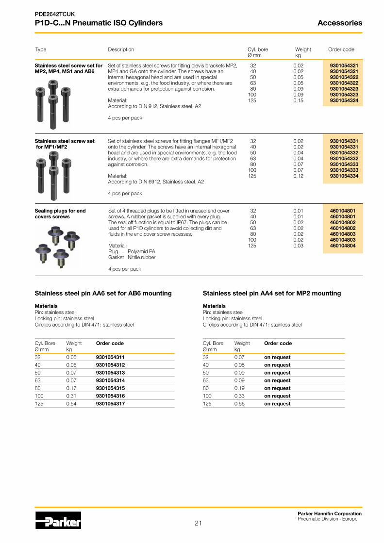
P1D-C...N Pneumatic ISO Cylinders Accessories
Stainless steel screw set for Set of stainless steel screws for fitting clevis brackets MP2,MP2, MP4, MS1 and AB6 MP4 and GA onto the cylinder. The screws have an
internal hexagonal head and are used in special environments, e.g. the food industry, or where there are extra demands for protection against corrosion. Material: According to DIN 912, Stainless steel, A2 4 pcs per pack.
Stainless steel screw set Set of stainless steel screws for fitting flanges MF1/MF2 for MF1/MF2 onto the cylinder. The screws have an internal hexagonal
head and are used in special environments, e.g. the food industry, or where there are extra demands for protection against corrosion. Material: According to DIN 6912, Stainless steel, A2 4 pcs per pack
Sealing plugs for end Set of 4 threaded plugs to be fitted in unused end cover covers screws screws. A rubber gasket is supplied with every plug. The seal off function is equal to IP67. The plugs can be used for all P1D cylinders to avoid collecting dirt and fluids in the end cover screw recesses. Material: Plug Polyamid PA Gasket Nitrile rubber 4 pcs per pack
32 0,02 9301054321 40 0,02 9301054321 50 0,05 9301054322 63 0,05 9301054322 80 0,09 9301054323100 0,09 9301054323125 0,15 9301054324
32 0,02 9301054331 40 0,02 9301054331 50 0,04 9301054332 63 0,04 9301054332 80 0,07 9301054333100 0,07 9301054333125 0,12 9301054334
32 0,01 460104801 40 0,01 460104801 50 0,02 460104802 63 0,02 460104802 80 0,02 460104803100 0,02 460104803125 0,03 460104804
Type Description Cyl. bore Weight Order code Ø mm kg
Stainless steel pin AA6 set for AB6 mounting
MaterialsPin: stainless steelLocking pin: stainless steelCirclips according to DIN 471: stainless steel
Cyl. Bore Weight Order codeØ mm kg
32 0.05 9301054311
40 0.06 9301054312
50 0.07 9301054313
63 0.07 9301054314
80 0.17 9301054315
100 0.31 9301054316
125 0.54 9301054317
Stainless steel pin AA4 set for MP2 mounting
MaterialsPin: stainless steelLocking pin: stainless steelCirclips according to DIN 471: stainless steel
Cyl. Bore Weight Order codeØ mm kg
32 0.07 on request
40 0.08 on request
50 0.09 on request
63 0.09 on request
80 0.19 on request
100 0.33 on request
125 0.56 on request
22
Seal kits
Parker Hannifin CorporationPneumatic Division - Europe
PDE2642TCUK
P1D-C...N Pneumatic ISO Cylinders
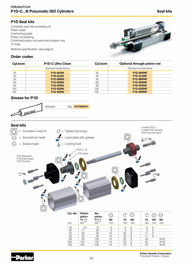
Grease for P1D Standard 30g 9127394541
Order codes
Cyl.bore Optional through piston rod Standard temperature
32 P1D-6KRNF 40 P1D-6LRNF 50 P1D-6MRNF 63 P1D-6NRNF 80 P1D-6PRNF 100 P1D-6QRNF 125 P1D-6RRNF
P1D Seal kitsComplete seal kits consisting of:Piston sealsCushioning seals Piston rod bearing Combined piston rod seal and scraper ring O-rings
Material specification, see page 8
T1
T2T2
Loctite 270 or Loctite 2701 locking fluid must be used
P1D-C...N
P1D otherP1D-StandardP1D-Ultra CleanP1D-Tie Rod
Cyl.bore P1D-C Ultra Clean Standard temperature
32 P1D-6KRN 40 P1D-6LRN 50 P1D-6MRN 63 P1D-6NRN 80 P1D-6PRN 100 P1D-6QRN 125 P1D-6RRN
Cyl.-dia Plastic Alu. piston piston T1 T1 NV T2 NV T3 NV NVmm Nm Nm mm Nm mm Nm mm mm
32 4,5 15 6 8 6 6 6 40 11 30 8 8 6 6 6 50 20 40 10 20 8 11 8 63 20 40 10 20 8 11 8 80 40 120 14 20 6 20 3x16100 120 120 14 20 6 20 3x16125 120 120 14 70 8 40 4x18
Seal kits= Included in seal kit = Tightening torque
= Screwdriver head = Lubricated with grease
= Socket head = Locking fluid

23
Parker Hannifin CorporationPneumatic Division - Europe
PDE2642TCUK
P1D-C...N Pneumatic ISO Cylinders Spare Parts
Cylinder dia. mm
032
040
050
063
080
100
125
Stroke** (mm) e.g. 0100 = 100 mm
Any stroke up to max. 2800 mm.
** When ordering piston rods for cylinders with an extended piston rod, add together the stroke and the extension in the order key. For example, a cylinder with stroke 100 mm and a piston rod extension of 25 mm is ordered with 0125 in the order number.
1 2 3 4 5 6 7 8 9 10 11 12 13 14 15
P 1 D – 8 0 3 2 D G – 0 1 0 0
Piston rod*
D Standard external thread
G Standard internal thread
H Through rod ext. threads
J Through rod int. threads
Cylinder barrel
N Smooth profile (without T slots)
Piston rod
G Stainless steel
H Hard-chromium plated
J Acid-resistant steel
K Chromium plated stainless
Cylinder barrel
A Aluminium
Order code key, spare parts
8 Spare parts
* 2 piston rod pieces delivered in one set if through rod option selected
P1D without T slots
Piston rod
Cylinder barrel type N

24
Parker Hannifin CorporationPneumatic Division - Europe
PDE2642TCUK
P1D-C...N Pneumatic ISO Cylinders
15-digit order code
6-7-8 7-86 Rod extension only
Cylinder bore mm
032
040
050
063
080
100
125
Cylinder bore mm
K 32
L 40
M 50
N 63
P 80
Q 100
R 125
Piston rod extension
E.g. KR5 = Cylinder bore 32 mm with piston rod extension = 255 mm
01-99 1-99 N0-N9 220-229
A0-A9 100-109 P0-P9 230-239
B0-B9 110-119 Q0-Q9 240-249
C0-C9 120-129 R0-R9 250-259
D0-D9 130-139 S0-S9 260-269
E0-E9 140-149 T0-T9 270-279
F0-F9 150-159 U0-U9 280-289
G0-G9 160-169 V0-V9 290-299
H0-H9 170-179 W0-W9 300-309
J0-J9 180-189 X0-X9 310-319
K0-K9 190-199 Y0-Y9 320-329
L0-L9 200-209 Z0-Z9 330-339
M0-M9 210-219 Longer on request
Stai
nles
s st
eel
Chr
omiu
m-p
late
d st
eel
Aci
d-pr
oof s
teel
Chr
om.-p
l. st
ainl
ess
stee
l
Piston rod Seals material
S C M R Standard -20 °C to +70 °C.
10
Order code key
* Note: Model code with 20 digits used only for the trunnion option or for a female thread on the piston rod.
1) Piston rod thread according to the ISO-standard. Other threads on request.
2) P1D Ultra Clean without sensor function.
3) XV-measure (from the piston rod thread according to ISO to the centre of the pivots) stated in mm in positions 18-20.
Max 700 mm stroke length for P1D-C with centre trunnion.
P1D cylinders are always delivered with one piston rod nut in stainless steel.
Piston rod thread 1)
6 Internal piston rod thread
Integrated Sensor System
N Without sensor 2)
11
Stroke (mm) e.g. 0100 = 100 mm
Optional stroke lengths up to 2800 mm. Standard strokes see table page 7
12-13-14-15
20-digit order code *
Cylinder version
C Ultra Clean smooth profile 2)
5
9
Std
scra
per
HD
PE s
crap
er)
FPM
ssc
rape
r
Std
scra
per
HD
PE s
crap
er
FPM
ssc
rape
r
End cover screws Function Standard Stainless steel
M D V A H W Double-acting
F E B G Y Z Double-acting through rod
17-18-19-20
Centre trunnion mountings
90° 0° See page 20 for orientation details
D - Centre trunnion MT4, mid position NNN digits 18-19-20
G - Trunnion MT4, optional pos. (XV-meas. digits 18-19-20)
1 2 3 4 5 6 7 8 9 10 11 12 13 14 15 16 17 18 19 20
P 1 D - C 0 4 0 M S N 0 3 2 0 N D N N N
19
16 17 18 19 20
N D N N N 1 2 3 4 5 6 7 8 9 10 11 12 13 14 15
P 1 D – B 0 3 2 M S – 0 1 0 0

25
Parker Hannifin CorporationPneumatic Division - Europe
PDE2642TCUK
P1D-C...N Pneumatic ISO Cylinders
Specifying air quality (purity) in accordance with ISO8573-1:2010, the international standard for Compressed Air QualityISO8573-1 is the primary document used from the ISO8573 series as it is this document which specifies the amount of contamination allowed in each cubic metre of compressed air.
ISO8573-1 lists the main contaminants as Solid Particulate, Water and Oil. The purity levels for each contaminant are shown separately in tabular form,
however for ease of use, this document combines all three contaminants into one easy to use table.
ISO8573-1:2010 CLASS
Solid Particulate Water Oil
Maximum number of particles per m3 MassConcentration
mg/m3
Vapour Pressure
Dewpoint
Liquid g/m3
Total Oil (aerosol liquid and vapour)
0,1 - 0,5 micron 0,5 - 1 micron 1 - 5 micron mg/m3
0 As specified by the equipment user or supplier and more stringent than Class 1
1 ≤ 20 000 ≤ 400 ≤ 10 - ≤ -70 °C - 0,01
2 ≤ 400 000 ≤ 6 000 ≤ 100 - ≤ -40 °C - 0,1
3 - ≤ 90 000 ≤ 1 000 - ≤ -20 °C - 1
4 - - ≤ 10 000 - ≤ +3 °C - 5
5 - - ≤ 100 000 - ≤ +7 °C - -
6 - - - ≤ 5 ≤ +10 °C - -
7 - - - 5 - 10 - ≤ 0,5 -
8 - - - - - 0,5 - 5 -
9 - - - - - 5 - 10 -
X - - - > 10 - > 10 > 10
Specifying air purity in accordance with ISO8573-1:2010
When specifying the purity of air required, the standard must always be referenced, followed by the purity class selected for each contaminant (a different purity class can be selected for each contamination if required).
An example of how to write an air quality specification is shown below:
ISO 8573-1:2010 Class 1.2.1ISO 8573-1:2010 refers to the standard document and its revision, the three digits refer to the purity classifications selected for solid particulate, water and total oil. Selecting an air purity class of 1.2.1 would specify the following air quality when operating at the standard’s reference conditions :
Class 1 - ParticulateIn each cubic metre of compressed air, the particulate count should not exceed 20,000 particles in the 0.1 - 0.5 micron size range, 400 particles in the 0.5 - 1 micron size range and 10 particles in the 1 - 5 micron size range.
Class 2 - WaterA pressure dewpoint (PDP) of -40°C or better is required and no liquid water is allowed.
Class 1 - OilIn each cubic metre of compressed air, not more than 0.01mg of oil is allowed. This is a total level for liquid oil, oil aerosol and oil vapour.
ISO8573-1:2010 Class zero • Class0doesnotmeanzerocontamination.
• Class 0 requires the user and the equipment manufacturer to agree contamination levels as part of a written specification.
• TheagreedcontaminationlevelsforaClass0specificationshould be within the measurement capabilities of the test equipment and test methods shown in ISO8573 Pt 2 to Pt 9.
• The agreed Class 0 specification must be written on all documentation to be in accordance with the standard.
• StatingClass0withouttheagreedspecificationismeaninglessand not in accordance with the standard.
• Anumberofcompressormanufacturersclaimthatthedeliveredair from their oil-free compressors is in compliance with Class 0.
• Ifthecompressorwastestedincleanroomconditions,thecontamination detected at the outlet will be minimal. Should the same compressor now be installed in typical urban environment, the level of contamination will be dependent upon what is drawn into the compressor intake, rendering the Class 0 claim invalid.
• AcompressordeliveringairtoClass0willstillrequirepurificationequipment in both the compressor room and at the point of use for the Class 0 purity to be maintained at the application.
• Airforcriticalapplicationssuchasbreathing,medical,food,etctypically only requires air quality to Class 2.2.1 or Class 2.1.1.
• PurificationofairtomeetaClass0specificationisonlycosteffective if carried out at the point of use.

26
Parker Hannifin CorporationPneumatic Division - Europe
PDE2642TCUK
P1D-C...N Pneumatic ISO Cylinders

27
Parker Hannifin CorporationPneumatic Division - Europe
PDE2642TCUK
P1D-C...N Pneumatic ISO Cylinders

Your local authorized Parker distributor
Parker Worldwide
Catalogue PDE2642TCUK - V4 - June 2014© 2014 Parker Hannifin Corporation. All rights reserved.
Parker Hannifin Ltd. Tachbrook Park DriveTachbrook Park, Warwick, CV34 6TUUnited Kingdom Tel.: +44 (0) 1926 317 878 Fax: +44 (0) 1926 317 [email protected]
Europe, Middle East, AfricaAE – United Arab Emirates, Dubai Tel: +971 4 8127100 [email protected]
AT – Austria, Wiener NeustadtTel: +43 (0)2622 23501-0 [email protected]
AT – Eastern Europe, Wiener Neustadt Tel: +43 (0)2622 23501 900 [email protected]
AZ – Azerbaijan, BakuTel: +994 50 2233 458 [email protected]
BE/LU – Belgium, NivellesTel: +32 (0)67 280 900 [email protected]
BY – Belarus, MinskTel: +375 17 209 9399 [email protected]
CH – Switzerland, EtoyTel: +41 (0)21 821 87 00 [email protected]
CZ – Czech Republic, KlecanyTel: +420 284 083 111 [email protected]
DE – Germany, KaarstTel: +49 (0)2131 4016 0 [email protected]
DK – Denmark, BallerupTel: +45 43 56 04 00 [email protected]
ES – Spain, MadridTel: +34 902 330 001 [email protected]
FI – Finland, VantaaTel: +358 (0)20 753 2500 [email protected]
FR – France, Contamine s/ArveTel: +33 (0)4 50 25 80 25 [email protected]
GR – Greece, AthensTel: +30 210 933 6450 [email protected]
HU – Hungary, BudapestTel: +36 1 220 4155 [email protected]
IE – Ireland, DublinTel: +353 (0)1 466 6370 [email protected]
IT – Italy, Corsico (MI)Tel: +39 02 45 19 21 [email protected]
KZ – Kazakhstan, AlmatyTel: +7 7272 505 800 [email protected]
NL – The Netherlands, OldenzaalTel: +31 (0)541 585 000 [email protected]
NO – Norway, AskerTel: +47 66 75 34 00 [email protected]
PL – Poland, WarsawTel: +48 (0)22 573 24 00 [email protected]
PT – Portugal, Leca da PalmeiraTel: +351 22 999 7360 [email protected]
RO – Romania, BucharestTel: +40 21 252 1382 [email protected]
RU – Russia, MoscowTel: +7 495 645-2156 [email protected]
SE – Sweden, SpångaTel: +46 (0)8 59 79 50 00 [email protected]
SK – Slovakia, Banská BystricaTel: +421 484 162 252 [email protected]
SL – Slovenia, Novo MestoTel: +386 7 337 6650 [email protected]
TR – Turkey, IstanbulTel: +90 216 4997081 [email protected]
UA – Ukraine, KievTel +380 44 494 2731 [email protected]
UK – United Kingdom, WarwickTel: +44 (0)1926 317 878 [email protected]
ZA – South Africa, Kempton ParkTel: +27 (0)11 961 0700 [email protected]
North AmericaCA – Canada, Milton, OntarioTel: +1 905 693 3000
US – USA, Cleveland Tel: +1 216 896 3000
Asia PacificAU – Australia, Castle HillTel: +61 (0)2-9634 7777
CN – China, ShanghaiTel: +86 21 2899 5000
HK – Hong Kong Tel: +852 2428 8008
IN – India, MumbaiTel: +91 22 6513 7081-85
JP – Japan, TokyoTel: +81 (0)3 6408 3901
KR – South Korea, SeoulTel: +82 2 559 0400
MY – Malaysia, Shah AlamTel: +60 3 7849 0800
NZ – New Zealand, Mt WellingtonTel: +64 9 574 1744
SG – Singapore Tel: +65 6887 6300
TH – Thailand, BangkokTel: +662 186 7000 99
TW – Taiwan, TaipeiTel: +886 2 2298 8987
South AmericaAR – Argentina, Buenos AiresTel: +54 3327 44 4129
BR – Brazil, Sao Jose dos CamposTel: +55 800 727 5374
CL – Chile, SantiagoTel: +56 2 623 1216
MX – Mexico, ApodacaTel: +52 81 8156 6000
European Product Information Centre
Free phone: 00 800 27 27 5374
(from AT, BE, CH, CZ, DE, DK, EE, ES, FI,
FR, IE, IL, IS, IT, LU, MT, NL, NO, PL, PT, RU,
SE, SK, UK, ZA)