PMS2000 PROFESSIONAL MODULAR SYSTEM SISTEMA …
52
- PMS2000 System - Ref. 11/595 PMW500-V PMW500-V SISTEMA MODULARE PROFESSIONALE PMS2000 PMS2000 PROFESSIONAL MODULAR SYSTEM Istruzioni per l’uso Instructions for use Manuel d’utilisation Gebrauchsanleitung Gebruiksinstructies Instrucciones de empleo Unità di potenza Booster Unité de puissance Leistungseinheit Vermogenseenheden Unidad de potencia PMW500-V dB ON -10 SPK -3 OVL -40 GND -6 AMP. 0 HOT ON OFF POWER PROFESSIONAL MODULAR SYSTEM 1
Transcript of PMS2000 PROFESSIONAL MODULAR SYSTEM SISTEMA …

- PMS2000 System -
Ref. 11/595 PMW500-V
- PMS2000 System -
Ref. 11/595 PMW500-V
PMW500-V
SISTEMA MODULARE PROFESSIONALE PMS2000PMS2000 PROFESSIONAL MODULAR SYSTEM
Istruzioni per l’usoInstructions for useManuel d’utilisationGebrauchsanleitungGebruiksinstructiesInstrucciones de empleo
Unità di potenzaBoosterUnité de puissanceLeistungseinheitVermogenseenhedenUnidad de potencia
PMW500-V
dB
ON
-10
SPK
-3
OVL
-40
GND
-6
AMP.
0
HOT
ON
OFF
POWER
PROFESSIONAL
MODULAR SYSTEM
Via Mecenate, 90 - 20138 MILANO - ITALIATEL. +39-02-580 77 1 (15 linee r.a.)
FAX +39-02-580 77 277http://www.paso.it
Printed in Italy - 11/06 - 0.02K - 11/595
NOTALa PASO declina ogni responsabilità per danni a cose e/o persone derivanti dall'uso non corretto dell'apparecchio o da procedurenon rispondenti a quanto riportato sul presente libretto. Nel continuo intento di migliorare i propri prodotti, la PASO S.p.A. siriserva il diritto di apportare modifiche ai disegni e alle caratteristiche tecniche in qualsiasi momento e senza alcun preavviso.
NOTEPASO will not accept any liability for damage to property and/or persons arising out of incorrect use of the equipment or ofprocedures that do not comply with the instructions provided in this booklet. PASO S.p.A. strive to improve their productscontinuously, and therefore reserve the right to make changes to the drawings and technical specifications at any time andwithout notice.
NOTEPASO décline toute responsabilité en cas de dommages matériels et/ou physiques provoqués par l'utilisation impropre del'appareil ou encore par des opérations ou des interventions ne respectant pas les instructions figurant dans la présente notice.En raison de l’amélioration constante de ses produits, PASO S.p.A. se réserve le droit d’apporter des modifications aux dessinset caractéristiques techniques à tout instant et sans préavis aucun.
MERKEPASO lehnt jede Haftung für Schäden an Personen und / oder Gegenständen ab, die durch unzweckmäßige Verwendung oderVorgehen entstehen, die nicht den Anweisungen dieses Handbuches entsprechen. In der Überzeugung, die eigenen Produktebeständig verbessern zu wollen, behält sich PASO S.p.A. das Recht vor, jederzeit und ohne Vorankündigung Änderungen antechnischen Zeichnungen und - Merkmalen vorzunehmem.
OPMERKINGPASO kan niet aansprakelijk worden gesteld voor schade aan voorwerpen en/of persoonlijk letsel die het gevolg zijn van eenonjuist gebruik van het apparaat of van procedures die niet overeenkomen met de voorschriften uit deze handleiding. AangezienPASO S.p.A. voortdurend verbeteringen aanbrengt aan haar producten, behoudt zij zich het recht voor op ieder moment zondervoorbericht de tekeningen en technische eigenschappen aan wijzigen te onderwerpen.
NOTALa PASO rehusa cualquier responsabilidad ante daños a cosas y/o personas causados por una utilización no correcta del aparatoo por operaciones no conformes a cuanto indicado en este folleto. Siempre con la firme intención de mejorar sus productos, PasoS.p.A. se reserva el derecho de modificar los dibujos y las características técnicas, sin preaviso alguno.
52 1
S.p.A
- PMS2000 System -
Ref. 11/595 PMW500-V
- PMS2000 System -
Ref. 11/595 PMW500-V
IntroduzioneNel ringraziarVi per aver scelto un prodotto PASO, vogliamoricordarVi che la nostra azienda opera con sistema di qualitàcertificato. Tutti i nostri prodotti vengono pertanto controllati inogni fase della produzione per garantirVi la piena soddisfazionedel Vostro acquisto. Per ogni evenienza la garanzia coprirà, nelperiodo di validità, eventuali difetti di fabbricazione.Vi raccomandiamo di leggere attentamente le seguenti istruzionid’uso per sfruttare appieno le prestazioni offerte da questoprodotto e per evitare eventuali problemi.
IntroductionWhile thanking you for having chosen a PASO product, we wouldlike to remind you that our company works according to a certifiedQuality System. This means that all our products are checkedduring every phase of manufacturing in order to ensure that youwill be fully satisfied with your purchase. In any case, theguarantee will cover any manufacturing flaws during theguarantee period. We recommend that you read the followinginstructions for use and follow them carefully in order to exploitin full the performance of this product and use it correctly.
SOMMARIO
1. Descrizione generale .......................................... 31.1 Pannello frontale ...................................................... 31.2 Pannello posteriore ................................................... 3
2. Avvertenze generali ........................................... 42.1 Installazione ............................................................. 42.2 Alimentazione e messa a terra .................................. 42.3 Note di sicurezza ...................................................... 4
3. Connessioni ........................................................ 53.1 Criteri generali ......................................................... 53.2 Ingresso/uscita di linea ............................................. 53.3 Uscite di potenza ...................................................... 5
• Regolazione del volume ......................................... 53.3.1 Sistemi a tensione costante ...................................... 63.4 Scheda traslatore di linea ......................................... 73.5 Scheda di controllo ................................................... 73.5.1 Connessioni .............................................................. 7
• Collegamento alla linea altoparlanti ........................ 8• Collegamento ingressi (opzionale) .......................... 8• Collegamento relè ................................................. 8• Funzionamento del relè ......................................... 8• Impostazione della modalità di funzionamento ....... 8• Potenziometro remoto ........................................... 8• Connettore ‘REMOTE CONTROL’ ............................. 9
3.5.2 Modalità di funzionamento ........................................ 9a) Modalità ‘STAND-ALONE’ ...................................... 9
• Acquisizione dell’impianto ................................. 9• Impostazione dell’intervallo
tra un test ed il successivo .............................. 10• Display a led ................................................... 10• Controllo di volume ......................................... 10• Selezione degli ingressi ................................... 11• Filtro ‘LOW CUT’ ............................................. 12• Modalità di risparmio energetico ...................... 12
b) Modalità ‘REMOTE CONTROL’ ............................. 12• Impostazione indirizzo .................................... 12
3.5.3 Calibrazione ........................................................... 13
4. Uso dell’apparecchio ........................................ 144.1 Accensione ............................................................. 144.2 Display ................................................................... 14
5. Note di servizio ................................................ 145.1 Ventilazione forzata ................................................ 145.2 Condizioni di sovraccarico e protezioni .................... 145.3 Tarature ................................................................. 15
6. Caratteristiche tecniche ................................... 15
7. Accessori .......................................................... 16
8. Lista delle parti di ricambio ............................. 16
• Tavola di configurazione ...................................... 47/48
• Ricerca guasti ........................................................... 49
TABLE OF CONTENTS
1. General description ........................................... 31.1 Front panel .............................................................. 31.2 Rear panel ............................................................... 3
2. General warnings .............................................. 42.1 Installation .............................................................. 42.2 Power supply and connection to earth ..................... 42.3 Safety notes ............................................................ 4
3. Connections ....................................................... 53.1 General criteria ........................................................ 53.2 Line input/output ..................................................... 53.3 Power outputs ......................................................... 5
• Volume control ...................................................... 53.3.1 Constant-voltage systems ........................................ 63.4 Line transformer card .............................................. 73.5 Control card ............................................................. 73.5.1 Connections ............................................................. 7
• Connection to the loudspeakers line ...................... 8• Connecting the inputs (optional) ........................... 8• Connecting the relay ............................................. 8• Operation of the relay ........................................... 8• Setting the operating mode ................................... 8• Remote potentiometer .......................................... 8• ‘REMOTE CONTROL’ Connector ............................. 9
3.5.2 Operating modes ..................................................... 9a) ‘STAND-ALONE’ mode ......................................... 9
• Acquisition of the system ................................. 9• Setting the interval
between one test and the next ....................... 10• LED display .................................................... 10• Volume control ............................................... 10• Selection of inputs ......................................... 11• ‘LOW CUT’ Filter ............................................. 12• Energy-saving mode ....................................... 12
b) ‘REMOTE CONTROL’ Mode ................................. 12• Address assignment ....................................... 12
3.5.3 Calibration ............................................................. 13
4. Using the equipment ....................................... 144.1 Switching on .......................................................... 144.2 Display .................................................................. 14
5. Service notes ................................................... 145.1 Forced ventilation .................................................. 145.2 Overload conditions and protection devices ............ 145.3 Adjustments .......................................................... 15
6. Technical specifications .................................. 15
7. Accessories ....................................................... 16
8. List of spare parts ............................................ 16
• Configuration table ............................................. 47/48
• Failure conditions ..................................................... 49
2 51
MODEL / MODELO / MODEL: ..........................................................................................................................................................
SERIAL NUMBER / NÚMERO DE SERIE / SERIENUMMER: ................................................................................................................
PURCHASE DATE / FECHA DE COMPRA / AANKOOPDATUM: ............................................................................................................
Belangrijke informatie voor de verwerking van het product in overeenstemming met de EuropeseRichtlijn 2002/96/EC Aan het einde van zijn levensduur mag het product niet samen met het gewone huishoudelijkeafval worden verwerkt. Het moet naar het daartoe bestemde gemeentelijke verzamelpunt voor gescheiden afvalworden gebracht, of naar een verkooppunt dat deze service verleent. Het apart verwerken van afgedankte elektrischeen elektronische apparatuur (AEEA) voorkomt mogelijk negatieve gevolgen voor het milieu en de gezondheid diedoor een ongeschikte verwerking ontstaan en zorgt ervoor dat de materialen waaruit het apparaat is samengesteldteruggewonnen kunnen worden om een aanmerkelijke besparing van energie en grondstoffen te verkrijgen. Om opde verplichting tot gescheiden verwerking van elektrische apparatuur te wijzen, is op het product het symbool vaneen doorgekruiste vuilnisbak aangebracht.
Garantie • Dit product is gegarandeerd vrij van materiaal- en constructiefouten; de garantieduur wordt geregeld door de geldendewettelijke voorschriften. Paso voert de reparatie van de hier gegarandeerde defecte producten kosteloos uit, indien blijkt dat hetdefect tijdens normaal gebruik is opgetreden. De garantie heeft dus geen betrekking op verkeerd gebruikte of geïnstalleerdeproducten, producten die mechanisch beschadigd zijn of beschadigingen hebben opgelopen door vloeistoffen of de invloed vanweersomstandigheden. Producten waarbij een defect is geconstateerd dienen franco verzend- en retourkosten aan Paso opgestuurdte worden. Deze garantie omvat geen enkele andere expliciete of impliciete garantie en dekt geen schade aan personen of zaken.Voor verdere informatie over de garantie dient contact opgenomen te worden met de dichtstbijzijnde PASO distributeur.
Belangrijk! De gebruik(st)er is verantwoordelijk voor het overleggen van een aankoopbewijs (factuur of ontvangstbewijs), indien hij/zij gebruik wenst te maken van door de garantie gedekte assistentie. Bovendien moet hij/zij opgave doen van de aankoopdatum, hetmodel en serienummer, die op het apparaat zijn aangebracht. Vul daarom de gevraagde gegevens hieronder in, als geheugensteun.
Dit product is conform de Richtlijnen van de Europese Gemeenschap waaronder het valt.
Important information for disposal of the product in accordance with EC Directive 2002/96/ECThis product must not be disposed of as urban waste at the end of its working life. It must be taken to a special wastecollection centre licensed by the local authorities or to a dealer providing this service. Separate disposal of electricand/or electronic equipment (WEEE) will avoid possible negative consequences for the environment and for healthresulting from inappropriate disposal, and will enable the constituent materials to be recovered, with significantsavings in energy and resources. As a reminder of the need to dispose of this equipment separately, the product ismarked with a crossed-out wheeled dustbin.
Warranty • This product is warranted to be free from defects in raw materials and assembly. The warranty period is governed bythe applicable provisions of law. Paso will repair the product covered by this warranty free of charge if it is faulty, provided the defecthas occurred during normal use. The warranty does not cover products that are improperly used or installed, mechanically damagedor damaged by liquids or the weather. If the product is found to be faulty, it must be sent to Paso free of charges for shipment andreturn. This warranty does not include any others, either explicit or implicit, and does not cover consequential damage to propertyor personal injury. For further information concerning the warranty contact your local PASO distributor.
Important! Should the user wish to avail himself of servicing under the warranty, he must provide evidence of the purchase (invoiceor receipt). The user shall also indicate the date of purchase, model and serial number indicated on the equipment. For this reason,you should complete the box below as a reminder of the data required.
This product is in keeping with the relevant European Community Directives.
Advertencias para la eliminación correcta del producto según establece la Directiva Europea 2002/96/EC Al final de su vida útil, el producto no debe eliminarse junto a los residuos urbanos. Debe entregarse a centrosespecíficos de recogida selectiva establecidos por las administraciones municipales, o a los revendedores que facilitaneste servicio. Eliminar por separado un aparato eléctrico o electrónico (WEEE) significa evitar posibles consecuenciasnegativas para el medio ambiente y la salud derivadas de una eliminación inadecuada y permite reciclar los materialesque lo componen, obteniendo así un ahorro importante de energía y recursos. Para subrayar la obligación de eliminarpor separado el aparato, en el producto aparece un contenedor de basura móvil listado.
Este producto cumple con sus correspondientes Directivas de la Comunidad Europea.
Garantía • Este producto está garantizado libre de defectos en sus materias primas y en su montaje; el periodo de garantía se rigepor las normas vigentes. La Paso reparará gratuitamente el producto defectuoso aquí garantizado si el defecto resultará habersepresentado durante el uso normal; la garantía no ampara pues los productos utilizados e instalados de manera errónea, dañadosmecánicamente, dañados por líquidos o por agentes atmosféricos. El producto, que haya resultado defectuoso, deberá ser enviadoa la Paso con portes pagados de envío y de vuelta. Esta garantía no incluye otras, explícitas o implícitas, y no incluye daños oaccidentes consiguientes a personas o cosas. Contactar con los distribuidores PASO de la zona para más información acerca de lagarantía.
¡Importante! El usuario tiene la responsabilidad de presentar una prueba de compra (factura o recibo) si desea utilizar la asistenciaamparada por la garantía. Deberá así mismo demostrar la fecha de compra e indicar el modelo y el número de serie indicados en elaparato; con tal fin, rellenar como memorando de los datos necesarios el cuadro siguiente.

- PMS2000 System -
Ref. 11/595 PMW500-V
- PMS2000 System -
Ref. 11/595 PMW500-V
1. DESCRIZIONE GENERALEL’unità di potenza PMW500-V, abbinata al sistema PMS2000è in grado di rispondere ai requisiti richiesti dalla normativa IEC60849 riguardante i sistemi per la gestione delle emergenze edell'evacuazione VES (Voice Evacuation System).
I componenti del sistema modulare contrassegnati dal suffisso‘-V’ in coda al codice del prodotto sono stati realizzati al fine dicorrispondere alla normativa sopraccitata.
1.1 Pannello frontale[1] Feritoie d’aerazione.[2] Spia d’accensione.[3] Display a led.[4] Interruttore di rete.
PMW500-V
dB
ON
-10
SPK
-3
OVL
-40
GND
-6
AMP.
0
HOT
ON
OFF
POWER
PROFESSIONAL
MODULAR SYSTEM
1 32 4
CAUTION:DISCONNECT POWERSUPPLY CORDBEFORE CHANGINGFUSE.
CAUTION:TO REDUCE THE RISKOF FIRE, REPLACEONLY WITH SAMETYPE FUSE.
MAINS RATING CONSUMPT.
500W RMS 950W
FUSE
V
230V
50/60Hz
FUSE
T 10 A
CONSUMPT. 800W24V
POWER AMPLIFIERPMW500-V
50V00
90V 70V 100V16 5 9,4 20
FUSE
32A
MADE IN ITALY
CAUTION: DO NOT OBSTRUCT OPENING !
IN/OUT IN/OUT
C
O
N
T
R
O
L
I
/
OTO SPEAKER LINE
TO POWER OUTPUT
RELAY
NORMAL OPEN
COMMON
NORMAL CLOSED
V max 100V
I max 3A
IN +INPUT
LINE
IN -10
9
1
2
8
7
6
5
4
3
REMOTE VOL.
min. 10K LIN.
.
MODE
SEL
1
8
REMOTE CONTROL
LEVEL OK
91011121314
5 6 7 8
1.2 Pannello posteriore[5] Morsettiera per alimentazione esterna in c.c.[6] Morsettiera per collegamento diffusori.[7] Dip-switch per impostazioni di funzionamento.[8] Morsettiera connessioni.[9] Feritoie d’aerazione.[10] Prese per ingresso/uscita di linea.[11] Regolazione del volume d’uscita.[12] Connettore per controllo remoto.[13] Spina di rete con fusibile incorporato.[14] Fusibile di protezione per alimentazione esterna in c.c.
1.1 Front panel[1] Louvers.[2] Power signalling lamp.[3] LED display.[4] Mains switch.
1.2 Rear panel[5] Terminal strip for external DC power supply.[6] Terminal strip for loudspeakers connection.[7] Dip-switch for operational settings.[8] Connections terminal strip.[9] Louvers.[10] Line input/output sockets.[11] Output volume controller.[12] Remote-control connector.[13] Mains plug with built-in fuse.[14] Fuse for protecting the DC power supply.
1. GENERAL DESCRIPTIONThe PMW500-V booster, combined with the PMS2000 system,is capable of meeting the requirements of IEC standard 60849concerning systems for managing emergencies and evacuation(VES - Voice Evacuation System).
The components of the modular system with the suffix ‘-V’ atthe end of their product codes were designed specifically forcompliance with the standard in question.
Garantie • Ce produit est garanti comme étant exempt de défauts de matières premières et de fabrication. La durée de la garantieest conforme aux normes en vigueur. Paso réparera gratuitement tout produit défectueux en garantie dès lors que l'anomalie sevérifiera dans le cadre d'une utilisation normale du produit. La garantie ne couvre donc pas les produits utilisés et installés de façonerronée, endommagés mécaniquement ou encore souillés par des liquides ou des agents atmosphériques. Le produit défectueuxdevra être envoyé à Paso franco de frais d'expédition et de réexpédition. La présente garantie n'en inclut aucune autre, explicite ouimplicite, et ne couvre pas les lésions ou dommages causés aux personnes ou aux choses. Pour plus d'informations sur la garantie,veuillez contacter le distributeur PASO de votre zone.Important! L'utilisateur devra présenter une preuve d'achat (facture ou récépissé) pour pouvoir bénéficier de l'assistance engarantie. Il devra par ailleurs fournir la date d'achat, le modèle et le numéro de série reportés sur l'appareil. Veuillez à cette finremplir le mémento des données demandées dans le cadre ci-dessous.
Garantie • Für dieses Produkt wird eine Garantie für Rohmaterialfehler und Montagefehler gewährt; die Garantiezeit unterliegt dengültigen gesetzlichen Bestimmungen. Paso repariert das garantierte Produkt kostenlos, wenn sich herausstellt, dass der Defektwährend des normalen Gebrauchs aufgetreten ist; die Garantie erstreckt sich demnach nicht auf Produkte, die falsch gebraucht undinstalliert oder mechanisch, durch Flüssigkeiten oder Umwelteinflüsse beschädigt wurden. Das defekte Produkt muss francoVersandkosten für den Hin- und Rücktransport zu und von Paso gesendet werden. Diese Garantie schließt keine weiteren, explizitenoder impliziten Leistungen und Folgeschäden an Personen, Gegenständen oder Unfälle ein. Bitte wenden Sie sich an PASO-Fachhandelin Ihrer Gegend, wenn Sie weitere Informationen zu dieser Garantie wünschen.
Wichtig! Der Kunde muss einen Verkaufsbeleg (Rechnung oder Quittung) vorlegen, wenn er Serviceleistungen, die unter dieGarantie fallen, in Anspruch nehmen möchte. Er muss zu diesem Zweck außerdem das Kaufdatum angeben sowie das Modell und dieSeriennummer, die auf dem Gerät vermerkt sind. Diese Daten müssen in den unten stehenden Textkasten eingetragen werden.
50 3
Avvertenze per lo smaltimento di questo prodotto ai sensi della Direttiva Europea 2002/96/ECAlla fine della sua vita utile il prodotto non deve essere smaltito insieme ai rifiuti urbani, ma deve essere consegnatopresso gli appositi centri di raccolta differenziata predisposti dalla Vostra amministrazione comunale, oppure presso irivenditori che forniscono questo servizio. Smaltire separatamente un rifiuto elettrico e/o elettronico (RAEE) consentedi evitare possibili conseguenze negative per l’ambiente e per la salute derivanti da un suo smaltimento inadeguatoe permette di recuperare i materiali di cui è composto al fine di ottenere un importante risparmio di energia e dirisorse. Su ciascun prodotto è riportato a questo scopo il marchio del contenitore di spazzatura barrato.
Garanzia • Questo prodotto è garantito esente da difetti nelle sue materie prime e nel suo montaggio; il periodo di garanziaè regolamentato dalle norme vigenti. La Paso riparerà gratuitamente il prodotto difettoso qui garantito se il difetto risulteràessersi verificato durante l’uso normale; la garanzia non si estende quindi a prodotti usati ed installati in modo errato, danneggiatimeccanicamente, danneggiati da liquidi o da agenti atmosferici. Il prodotto, risultato difettoso, dovrà essere inviato alla Pasofranco di spese di spedizione e ritorno. Questa garanzia non ne comprende altre, esplicite od implicite, e non comprende dannio incidenti conseguenti a persone o cose. Contattare i distributori PASO della zona per maggiori informazioni sulla garanzia.
Importante! L'utente ha la responsabilità di produrre una prova d'acquisto (fattura o ricevuta) se vuole servirsi dell'assistenzacoperta da garanzia. Dovrà inoltre fornire data di acquisto, modello e numero di serie riportati sull'apparecchio; a questoscopo, compilare come promemoria dei dati richiesti lo spazio in basso.
Questo prodotto è conforme alle Direttive della Comunità Europea sotto le quali lo stesso ricade.
Recommandations pour l'élimination du produit conformément à la Directive Européenne 2002/96/ECAu terme de son utilisation, le produit ne doit pas être éliminé avec les déchets urbains. L'appareil doit être remis à l'undes centres de tri sélectif agréés par l'administration communale ou à un revendeur assurant ce service. L'éliminationdifférenciée des appareils électroniques (WEEE) permet non seulement d'éviter les retombées négatives pourl'environnement et la santé dues à une élimination incorrecte, mais aussi de récupérer les matériaux qui le composentet permet ainsi d'effectuer d'importantes économies en termes d'énergie et de ressources. Pour rappeler l'obligationd'éliminer séparément les appareils électroniques, le produit porte le symbole d'un caisson à ordures barré.
Ce produit est conforme aux Directives de la Communauté européenne auxquelles il est soumis.
MODELLO / MODÈLE / MODELL: .....................................................................................................................................................
NUMERO DI SERIE / NUMÉRO DE SÉRIE / SERIENNUMMER: ...........................................................................................................
DATA D’ACQUISTO / DATE D'ACHAT/ DATUM DES ERWERBS: .........................................................................................................
Dieses Produkt entspricht den diesbezüglichen EU-Richtlinien.
Wichtiger Hinweis für die Entsorgung des produkts in übereinstimmung mit der EG-richtlinie 2002/96/EC Am Ende seiner Nutzzeit darf das Produkt nicht zusammen mit dem Siedlungsabfall beseitigt werden,sondern es muss bei den zu diesem Zweck von den städtischen Behörden eingerichteten Sammelstellen oder zuden Fachhändlern, die einen Rücknahmeservice anbieten, gebracht werden. Die getrennte Entsorgung von Elektro-und Elektronik-Altgeräten (WEEE - Waste Electric and Electronic Equipment) vermeidet mögliche negativeAuswirkungen auf die Umwelt und die Gesundheit infolge einer nicht vorschriftsmäßigen Entsorgung. Zudemwird die Wiederverwertung der Materialen, aus denen das Gerät besteht, ermöglicht, so dass eine bedeutendeEinsparung an Energie und Ressourcen erzielt wird. Aus diesem Grund ist das Produkt mit dem Symbol einerdurchgestrichenen Mülltonne gekennzeichnet.

- PMS2000 System -
Ref. 11/595 PMW500-V
- PMS2000 System -
Ref. 11/595 PMW500-V
2. AVVERTENZE GENERALI2.1 InstallazioneTutti gli apparecchi PASO sono costruiti nel rispetto delle piùsevere normative internazionali di sicurezza ed in ottemperanzaai requisiti della Comunità Europea. Per un corretto ed efficaceuso dell’apparecchio è importante prendere conoscenza di tuttele caratteristiche leggendo attentamente le presenti istruzionied in particolare le note di sicurezza.Durante il funzionamento dell’apparecchio è necessarioassicurare un’adeguata ventilazione. Evitare di racchiuderel’apparecchio in un mobile privo di aerazione o di ostruirne lefessure di ventilazione.Evitare inoltre di tenere l’apparecchio in prossimità di sorgentidi calore (termosifoni, impianti di riscaldamento, ecc.).Prima dell’accensione assicurarsi che tutti gli ingressi e le uscitesiano correttamente collegati.
2.2 Alimentazione e messa a terraL’apparecchio è predisposto per il funzionamento con tensionedi rete a 230 V ± 10% 50/60 Hz. E’ prevista, in alternativa, lapossibilità di alimentare l’apparecchio con una tensione continuaesterna di 24V da applicare agli appositi morsetti ‘24V’ dellamorsettiera [5]. Tipicamente questa tensione proviene daaccumulatori mantenuti sotto carica in tampone ed entra infunzione soltanto in caso di emergenza; è necessario, in questocaso, prevedere l’uso di un relè esterno che connetta le batterieall’apparecchio solo quando viene a mancare l’alimentazione direte.L’apparecchio è protetto contro le inversioni di polarità.In accordo con le normative di sicurezza, l’ interruttore diaccensione [4] agisce solo sulla tensione di rete.
2.3 Note di sicurezzaOgni intervento all’interno dell’apparecchio, quale la selezionedi alcuni modi d’uso o l’applicazione di accessori, deve essereeffettuato solo da personale specializzato: la rimozione delcoperchio rende accessibili parti con rischio di scosse elettriche.Prima di rimuovere i pannelli di chiusura, accertarsi sempreche il cavo di rete sia staccato. Nel caso di accidentale cadutadi liquidi sull’apparecchio, staccare immediatamente la spinadi rete ed interpellare il centro di assistenza PASO più vicino.L’apparecchio é corredato di cavo di alimentazione con filo diterra ed il relativo terminale sulla spina di rete non deve essererimosso in alcun caso.Assicurarsi che la presa di corrente sia dotata di collegamentodi terra a norma di legge.
IMPORTANTE
I terminali marcati con il simbolo
sono attivi e pericolosi.Il cablaggio esterno collegato a questi terminali, DEVE essereeseguito esclusivamente da personale specializzato.
2. GENERAL WARNINGS2.1 InstallationAll PASO equipment is built according to the strictestinternational safety standards and complies with EuropeanCommunity requisites. In order to use the equipment correctlyand effectively, it is important to be aware of all its featuresby reading these instructions and in particular the notes onsafety carefully.While the equipment is working, it is necessary to ensureadequate ventilation. Avoid closing the equipment inside acabinet without ventilation and take care not to obstruct theventilation slits.Also avoid keeping the equipment near a source of heat(radiator, heating systems and so on).Before switching on the equipment, make sure that all theinputs and outputs are correctly connected.
2.2 Power supply and connection to earthThe equipment has provisions for operation with a mainsvoltage of 230 V ± 10% 50/60 Hz. As an alternative, it ispossible to power the equipment with an external continuousvoltage of 24V to be applied to the appropriate ‘24V’ terminalon the terminal strip [5].Typically, this voltage is taken from accumulators under floatcharged that only starts working in case of emergencies. Inthis case, it is necessary to envisage use of an external relayfor connecting the batteries to the equipment only when themains power supply fails.The equipment is protected against polarity inversions.In accordance with the safety regulations, the ON/OFF switch[4] is only effective for the mains power supply.
2.3 Safety notesAny work inside the equipment, such as selecting some of themodes of operation or applying accessories may only be carriedout by specialised personnel. On removing the cover, partsentailing a danger of electric shocks will be made accessible.Always make sure that the mains cable of the power-supplymodule is disconnected before removing the panels. If anyliquid is accidentally spilt on the equipment, disconnect themains cable immediately and contact the nearest PASO ServiceCentre. The equipment is supplied with its own power-supplycable with an earth wire. The relevant terminal on the mainsplug must never be removed, under any circumstances. Makesure that the power outlet has a connection to earth inaccordance with the law.
IMPORTANT
The terminals marked with the symbol
are active and dangerous.The external connections toward these terminals MUST becarried out by specialized personnel only.
4 49
!
" #$% &%#'(
!"#$
%&
!
'%
(("#$(
%&
%%)*
+,)-*
!"#$
%&
!
'%
(("#$
%&
.,
.,
%%% %!
%%/
0(/
1 2%%
1 2
% % %
%$)" )%$(* )%$(*)
- %
0/
3%3
33"#$
4%&
56(
!(("#$
76!/&5
- 3)
%*
%
3%3
33"#$
4%&
56(
!("#$
76!/&5
-.,%
.,0/
& 0%
89
!(%76/
-1 2
1 2%
&
%
8%76/
" )%$(+$ ,-)
/
%
%"#$
%%%
:
(
"#$
(
;%):*
0)*
%
%"#$
%%%
:
(
"#$
(
.,
.,/
%
<%-
/:
1 2
%
1 20
%<% =(
%/
.!/! !/0 !
!!! 1 !

- PMS2000 System -
Ref. 11/595 PMW500-V
- PMS2000 System -
Ref. 11/595 PMW500-V
3. CONNESSIONI3.1 Criteri generaliPer un corretto funzionamento dell’apparecchio è opportunoosservare alcuni criteri di massima nell’esecuzione deicollegamenti:- evitare il posizionamento di cavi e di microfoni sul mobile
dell’apparecchio.- evitare di stendere le linee di segnale parallele a quelle di
rete; osservare una distanza minima di 30/40 cm.- posizionare le linee di ingresso e le linee di uscita distanti
tra loro.- posizionare i microfoni al di fuori dell’angolo di radiazione dei
diffusori sonori per evitare il fenomeno di reazione acustica(effetto Larsen).
3.2 Ingresso/uscita di lineaSul pannello posteriore dell’apparecchio sono disponibili leprese XLR d’ingresso/uscita [10] per segnali a livello linea (0 dB,775 mV) dell’unità di potenza; le prese sono parallelate peragevolare il collegamento in cascata di più unità di potenza.In fig. 3.2.1 sono riportate le connessioni a queste prese.L’ingresso dell’amplificatore è bilanciato elettronicamente; perparticolari esigenze come, ad esempio, nel caso di lunghi cavidi collegamento e/o forti campi elettromagnetici disturbanti,é possibile isolare galvanicamente l’ingresso dell’amplificatoretramite la scheda opzionale TM92, dotata di traslatore di linea(vedi paragrafo 3.4).
Fig. 3.2.1
1: schermo / shield2: segnale (lato caldo) / signal (warm side)3: segnale (lato freddo) / signal (cold side)
3.3 Uscite di potenzaLe uscite di potenza per i diffusori sono disponibili sullamorsettiera per impianti di distribuzione a tensione costante(50,70, 90 e 100 V) [6].In tabella 3.3.1 sono riportati i valori nominali d’impedenzariferiti alle prese d’uscite a tensione costante.
USCITA PMW500-V50 V 5 Ω
70 V 9,4 Ω
90 V 16 Ω
100 V 20 Ω
Tab. 3.3.1
• Regolazione del volumeLa regolazione del volume di uscita può essere effettuatasemplicemente agendo sull'apposito trimmer ‘LEVEL’ [11]posto sul lato posteriore dell'apparecchio. Ruotando con unpiccolo giravite in senso orario, il livello viene incrementato;ruotando in senso antiorario, il livello viene decrementato.
Fig. 3.3.2
IN/OUT
2 1
3
IN/OUT.
E
SEL 8
REMOTE CONTROL
LEVEL OK
3. CONNECTIONS3.1 General criteriaIn order to allow the equipment to work correctly, it is advisableto comply with a number of general criteria when making theconnections:- Avoid positioning cables or microphones on the cabinet of the
equipment.- Avoid laying the signal lines parallel to the power-supply lines.
Keep a minimum distance of 30/40 cm.- Position the input lines and the output lines at a distance from
one another.- In order to avoid acoustic feedback (the Larsen effect), position
the microphones out of the angle of coverage of theloudspeakers.
3.2 Line input/outputThe XLR input/output sockets [10] for the line-level signals(0 dB, 775 mV) of the power unit are located on the rearpanel of the equipment. The sockets are paralleled in order tofacilitate cascade connection of several power units. Figure3.2.1 shows the connections to these sockets. The input ofthe ampli f ier is e lectronical ly balanced. For specia lrequirements such as, for example, in case of long connectingcables and/or strong electromagnetic fields that causeinterference, it is possible to insulate the amplifier inputgalvanically using the optional TM92 card, equipped with aline transformer (see paragraph 3.4).
3.3 Power outputsThe power outputs for the loudspeakers are available on theterminal strips for constant-voltage distribution systems(50,70, 90 and 100 V) [6].Table 3.3.1 shows the rated impedance values referred to theconstant-voltage output sockets.
OUTPUT PMW500-V50 V 5 Ω
70 V 9,4 Ω
90 V 16 Ω
100 V 20 Ω
Tab. 3.3.1
• Volume controlThe output volume can be adjusted simply by turning the‘LEVEL’ trimmer [11] provided for this purpose on the rearside of the equipment. It can be turned with a smallscrewdriver. In a clockwise direction the volume is increasedwhile in an anticlockwise direction the volume is decreased.
AVEL1
AVEL2
AVEL3
AVEL4
AVEL5
AVEL6
AVEL7
AVEL8
OZZIRIDNISSERDDA
NO FFO FFO FFO FFO FFO 23
NO FFO FFO FFO FFO NO 33
NO FFO FFO FFO NO FFO 43
NO FFO FFO FFO NO NO 53
NO FFO FFO NO FFO FFO 63
NO FFO FFO NO FFO NO 73
NO FFO FFO NO NO FFO 83
NO FFO FFO NO NO NO 93
NO FFO NO FFO FFO FFO 04
NO FFO NO FFO FFO NO 14
NO FFO NO FFO NO FFO 24
NO FFO NO FFO NO NO 34
NO FFO NO NO FFO FFO 44
NO FFO NO NO FFO NO 54
NO FFO NO NO NO FFO 64
NO FFO NO NO NO NO 74
NO NO FFO FFO FFO FFO 84
NO NO FFO FFO FFO NO 94
NO NO FFO FFO NO FFO 05
NO NO FFO FFO NO NO 15
NO NO FFO NO FFO FFO 25
NO NO FFO NO FFO NO 35
NO NO FFO NO NO FFO 45
NO NO FFO NO NO NO 55
NO NO NO FFO FFO FFO 65
NO NO NO FFO FFO NO 75
NO NO NO FFO NO FFO 85
NO NO NO FFO NO NO 95
NO NO NO NO FFO FFO 06
NO NO NO NO FFO NO 16
NO NO NO NO NO FFO 26
NO NO NO NO NO NO 36
48 5

- PMS2000 System -
Ref. 11/595 PMW500-V
- PMS2000 System -
Ref. 11/595 PMW500-V
Fig. 3.3.3
numero diffusori =impedenza nominale diffusore
impedenza amplificatore
numero diffusori =500 W10 W
= 50
• Calcolo del numero di diffusori(tramite le potenze)
Si supponga di avere definito sia l’amplificatore (cioé la suapotenza di uscita) che il tipo di diffusore con relativa potenzaassorbita. In questo caso il massimo numero di diffusoricollegabile sulla linea é determinato dalla seguente formula:
Esempio: si utilizzino un amplificatore PMW500-V, in grado dierogare una potenza pari a 500 watt, con plafoniere da 10watt nominali. Per sapere quanti diffusori sono collegabili allalinea di uscita si calcola:
3.3.1 Sistemi a tensione costanteIn questo tipo di impianto, i diffusori, provvisti di trasformatoridi adattamento d’ impedenza, sono tutt i col legat i inderivazione al la l inea (vedi es. di Fig. 3.3.3). Questoparticolare rende di facile realizzazione l’impianto e, nel casoin cui un altoparlante dovesse per qualche motivo scollegarsidalla linea, il resto dell’impianto proseguirebbe nel suo regolarefunzionamento. Le tensioni costanti disponibili in uscitadall’amplificatore sono da 50, 70, 90 e 100 V. Per il correttodimensionamento dell’impianto (scelta della tensione di lineadell’apparecchio e selezione della potenza del diffusore) épossibile individuare diverse procedure, di seguito riportatecon esempi numerici.
potenza amplificatorepotenza diffusore
numero diffusori =
• Calcolo del numero di diffusori(tramite le impedenze)
Se il dato disponibile é l’impedenza del diffusore, il numeromassimo di diffusori collegabili ad una linea é:
• Connessione alle terminazioni di linea PM2094-VPer il controllo dell’integrità della linea altoparlanti, è necessariocollegare alla fine della linea stessa due schede PM2094-V comemostrato in figura 3.3.3.N.B.: le schede devono avere lo stesso indirizzo logico; devonoinoltre essere inseriti i jumper CN106 e CN107 (vedi librettorelativo).
MAINS RATING CONSUMPT.
500W RMS 950W230V
50/60Hz
FUSE
T 10 A
CONSUMPT. 800W24V
POWER AMPLIFIERPMW500-V
FUSE
MADE IN ITALY
C
O
N
T
R
O
L
I
/
OTO SPEAKER LINE
TO POWER OUTPUT
RELAY
NORMAL OPEN
COMMON
NORMAL CLOSED
V max 100V
I max 3A
IN +INPUT
LINE
IN -10
9
1
2
8
7
6
5
4
3
REMOTE VOL.
min. 10K LIN.
N.B.: in impianti d’evacuazione VES (Voice Evacuation System) èobbligatorio eseguire le connessioni degli altoparlanti come illustrato.
3.3.1 Constant-voltage systemsIn this type of system the loudspeakers, which are equippedwith impedance-matching transformers, are all connected bybranching them from the line (see example in Figure 3.3.3).This fact makes the system easy to create and, if any of theloudspeakers should be disconnected from the line for anyreason, the rest of the system would continue to functionproperly. The constant voltages available as outputs from theamplifier are 50, 70, 90 and 100 V. There are several possibleprocedures for sizing the system correctly (by choosing theline voltage of the equipment or by choosing the output powerof the loudspeaker). Numerical examples of these proceduresare provided below.
• Connection to PM2094-V line terminationsIn order to monitor the integrity of the loudspeaker line, twoPM2094-V cards shall be connected to the end of the line asshown in Figure 3.3.3.N.B.: The cards must have the same logical address, andjumpers CN106 and CN107 must also be in place (see theappropriate booklet).
• Calculating the number of loudspeakers(on the basis of the power output)
It is assumed that both the amplifier (that is to say its outputpower) and the type of loudspeaker with the relevant absorbedpower have both been defined. In this case the maximumnumber of loudspeakers that can be connected to the line isdetermined by means of the following formula:
number of loudspeakers =amplifier power
loudspeaker power
Example: a PMW500-V booster capable of delivering an outputpower equal to 500 watt is used, with ceiling fixtures rated at10 watt. To find out how many loudspeakers can be connectedto the output line, calculate the following:
number of loudspeakers =500 W10 W
= 50
• Calculating the number of loudspeakers(on the basis of the impedance values)
If the available datum is the impedance of the loudspeaker, themaximum number of loudspeakers that can be connected to aline is:
dove l’impedenza nominale dell’amplificatore é ricavabile dallatabella 3.3.1 (pag. 5).
number of loudspeakers =loudspeaker rated impedance
amplifier impedance
N.B.: It is compulsory in VES’s (Voice Evacuation System) to makethe connections of the loudspeakers as illustrated.
Where the rated impedance of the amplifier can be found intable 3.3.1 (page 5).
ENOIZARUGIFNOCIDALOVAT • ELBATNOITARUGIFNOC
AVEL1
AVEL2
AVEL3
AVEL4
AVEL5
AVEL6
AVEL7
AVEL8
OZZIRIDNISSERDDA
FFO FFO FFO FFO FFO FFO 0
FFO FFO FFO FFO FFO NO 1
FFO FFO FFO FFO NO FFO 2
FFO FFO FFO FFO NO NO 3
FFO FFO FFO NO FFO FFO 4
FFO FFO FFO NO FFO NO 5
FFO FFO FFO NO NO FFO 6
FFO FFO FFO NO NO NO 7
FFO FFO NO FFO FFO FFO 8
FFO FFO NO FFO FFO NO 9
FFO FFO NO FFO NO FFO 01
FFO FFO NO FFO NO NO 11
FFO FFO NO NO FFO FFO 21
FFO FFO NO NO FFO NO 31
FFO FFO NO NO NO FFO 41
FFO FFO NO NO NO NO 51
FFO NO FFO FFO FFO FFO 61
FFO NO FFO FFO FFO NO 71
FFO NO FFO FFO NO FFO 81
FFO NO FFO FFO NO NO 91
FFO NO FFO NO FFO FFO 02
FFO NO FFO NO FFO NO 12
FFO NO FFO NO NO FFO 22
FFO NO FFO NO NO NO 32
FFO NO NO FFO FFO FFO 42
FFO NO NO FFO FFO NO 52
FFO NO NO FFO NO FFO 62
FFO NO NO FFO NO NO 72
FFO NO NO NO FFO FFO 82
FFO NO NO NO FFO NO 92
FFO NO NO NO NO FFO 03
FFO NO NO NO NO NO 13
6 47

- PMS2000 System -
Ref. 11/595 PMW500-V
- PMS2000 System -
Ref. 11/595 PMW500-V
3.4 Scheda traslatore di lineaPer installare questo accessorio è necessario rimuovere lacopertura dell’apparecchio. Dopo aver identificato il connettoreCN204 (part. [A], fig. 3.4.1)occorrerà rimuovere i ponticellicortocircuitanti in esso inseriti eposizionare, al loro posto, lascheda TM92.
Richiudere l’unità riposizionandola copertura.
Fig. 3.4.1
Fig. 3.5.1
3.5.1 ConnessioniLa morsett iera ‘CONTROL I/O ’[8] presente sul pannello posterioredell’amplificatore deve essere usata pereffettuare le principali connessioni.
3.5 Scheda di controlloAll’interno dell’amplificatore viene di serie montata la scheda dicontrollo PM2092-V, che è stata creata per consentirel'esecuzione semplice e veloce di test sull’ amplificatore stessoe della/e linee altoparlanti tramite l’utilizzo delle schedePM2094-V.Questa scheda gestisce tutte le funzioni dell'amplificatore, dagliingressi alla diagnostica ed è in grado di eseguire le seguentifunzioni:• misure di impedenza di linea;• diagnostica dell'amplificatore;• verifica dell’integrità della linea altoparlanti (PM2094-V).• verifica isolamento di terra (GND FAULT);• controllo di volume (locale o tramite potenziometro remoto);• selezione di due ingressi;• controllo del relè di potenza;• possibilità di inserimento del filtro LOW CUT;• funzionamento in modalità di risparmio energetico ‘LOW POWER’.La scheda può inoltre essere controllata tramite interfacciaseriale. Oltre ad eseguire tutte le operazioni e/o verificheimpostate localmente con i dip-switch, sarà possibile visualizzaree modificare tutti i parametri tra cui:• lettura dell'impedenza di riferimento per il test;• valore minimo e massimo entro cui il test risulta valido;• lettura dello stato dei test;• test dell'ingresso;• misura della temperatura dei transistor finali;• regolazione del volume;• comando remoto del relè.
C
O
N
T
R
O
L
I
/
OTO SPEAKER LINE
TO POWER OUTPUT
RELAY
NORMAL OPEN
COMMON
NORMAL CLOSED
V max 100V
I max 3A
IN +INPUT
LINE
IN -10
9
1
2
8
7
6
5
4
3
REMOTE VOL.
min. 10K LIN.
numero diffusori =833 Ω20 Ω
= 41
Esempio: si utilizzino un amplificatore PMW500-V con diffusoriche presentano una impedenza nominale pari a 833 ohm(corrispondenti ad una potenza di 12 watt su linea a 100 volt).Dalla tabella 3.3.1 si trova che l’impedenza nominale della lineadi uscita a 100 volt è pari a 20 ohm. Quindi:
Example: a PMW500-V booster with loudspeakers that have arated impedance of 833 ohm (corresponding to an output powerof 12 watt on a 100 volt line) is used. Based on table 3.3.1 it canbe seen that the rated output of the output line at 100 volt isequal to 20 ohm. Therefore:
number of loudspeakers =833 Ω20 Ω
= 41
3.4 Line transformer cardTo install this accessory, it is necessary to remove the cover ofthe equipment. After identifying connector CN204 (item [A],
Fig. 3.4.1), the short-circuitingjumpers in place on it will have tobe removed and a TM92 cardinserted in their place.
Close the unit by putting the coverback into place.
3.5 Control cardA PM2092-V is mounted inside the amplifier as a standard.This card was designed specifically to enable simple and rapidtests to be carried out on the amplifier itself and on theloudspeaker line(s) using the PM2094-V card.
This card manages all the functions of the amplifier, from theinputs to diagnostics, and is capable of carrying out the followingfunctions:• line impedance measurements;• amplifier diagnostics;• check of the integrity of the loudspeaker line (PM2094-V).• check of insulation to earth (GND FAULT);• volume control (local or by means of a remote potentiometer);• selection of two inputs;• check of the power relay;• possibility of including the LOW CUT filter;• operation in the ‘LOW POWER’ energy-saving mode.The card can also be controlled via a serial interface.In addition to carrying out all the operations and/or checks setlocally by means of the dip-switch, it will also be possible todisplay and alter all the parameters, including the following:• reading of the reference impedance for the test;• minimum and maximum values between which the test is valid;• reading of the test status;• testing of the input;• measurement of the temperature of the end transistors;• volume adjustment;• remote control of the relay.
3.5.1 ConnectionsThe ‘CONTROL I/O’ terminal strip[8] on the rear panel of the amplifierhas to be used to make the mainconnections.
CI202 R2
30
CN
20
4
C218
R2
29
R2
16
R2
36 R2
33
C2
20
R2
08
D2
18
D2
19
R226 C217
X2
07
C219
CC
N2
02
PR201PR202
X208
A
8. LIJST VERVANGINGSONDERDELEN
7. ACCESSOIRES
Kaart lijntransformator ................................................. TM92
7. ACCESORIOS
Tarjeta trasladador de línea .......................................... TM92
8. LISTA DE LAS PIEZAS DE REPUESTO
Gezeefdrukt frontpaneel 36/2481-S1 Panel frontal serigrafiado
Samenstel vermogenskring (Links) 27/4253 Conjunto circuito de potencia (IZDA)
Samenstel vermogenskring (Rechts) 27/4254 Conjunto circuito de potencia (DCHA
Samenstel circuit besturingskaart 27/4340-V Conjunto circuito tarjeta control
Samenstel circuit stroombegrenzer 27/4356 Conjunto circuito limitador de corriente
Samenstel circuit Vu-Meter 27/4370 Conjunto circuito Vu-Meter
Samenstel circuit bedieningen en besturing 27/4575 Conjunto circuito de mandos y pilotaje
Voedingstransformator TF197 Transformador de alimentación
Uitgangstransformator TU138/16 Transformador de salida
Geprogrammeerde micro 01PMW1.2 Micro programado
Netschakelaar 19/113 Interruptor de red
Handvat 38/341-VNO Asa
Koelventilator VT7 Ventilador de enfriamiento
Gelijkrichterbrug 50 A – 200 V 16/73 Rectificador 50 A - 200 V
Elektrolitische condensator 10000µF 63V 649060103 Condensador electrolítico 10000µF 63V
Keramische condensator 2,2 nF 400V 709010222 Condensador cerámico 2.2 nF 400V
Transistor TIP35 17/79 Transistor TIP35
Transistor BD911 17/65 Transistor BD911
46 7

- PMS2000 System -
Ref. 11/595 PMW500-V
- PMS2000 System -
Ref. 11/595 PMW500-V
• Collegamento ingressi (opzionale)Qualora si volesse collegare un secondo ingresso, utilizzare iterminali 8, 9 e 10 della morsettiera ‘CONTROL I/O’ [8] comemostrato in figura 3.5.2.
• Potenziometro remotoIl potenziometro remoto deveessere collegato ai terminali6, 7 e 8 del la morsettiera‘CONTROL I/O’ [8].
Fare riferimento alla figura 3.5.5per incrementare o decrementareil volume.
Fig. 3.5.5
• Collegamento alla linea altoparlantiCollegare il terminale 1 della morsettiera ‘CONTROL I/O’ [8]all’uscita di potenza 100 V. La linea altoparlanti deve essereinvece collegata al terminale 2 (vedi figura 3.3.3, pag. 6).
Fig. 3.5.2
C
O
N
T
R
O
L
I
/
OTO SPEAKER LINE
TO POWER OUTPUT
RELAY
NORMAL OPEN
COMMON
NORMAL CLOSED
V max 100V
I max 3A
IN +INPUT
LINE
IN -10
9
1
2
8
7
6
5
4
3
REMOTE VOL.
min. 10K LIN.
IN –
IN +C
O
N
T
R
O
L
I
/
OTO SPEAKER LINE
TO POWER OUTPUT
RELAY
NORMAL OPEN
COMMON
NORMAL CLOSED
V max 100V
I max 3A
IN +INPUT
LINE
IN -10
9
1
2
8
7
6
5
4
3
REMOTE VOL.
min. 10K LIN.
• Collegamento relèCome riportato sul pannello posteriore dell’amplificatore, icollegamenti del relè sono quelli illustrati in figura 3.5.3.
• Funzionamento del relèLe modalità di funzionamento del relè sono tre.La prima (MODE 0 - impostazione di fabbrica) prevede che ilrelè sia sempre eccitato e si disecciti solo per mancanza dialimentazione o guasto all’amplificatore. In questa modalità èpossibile, tramite l’utilizzo della scheda PM2095, impostareun sistema di più amplificatori con l’inserzione automatica diuna o più riserve. La seconda modalità (MODE 1), il relè èsempre eccitato e si diseccita solo in presenza di un guastosulla linea degli altoparlanti. Nella terza modalità (MODE 2), ilrelè è sempre eccitato e si diseccita se vi è un guasto di linea odell’amplificatore.
• Impostazione della modalità di funzionamentoViene di seguito illustrata la sequenza da effettuare per impostarele diverse modalità tramite il dip-switch della scheda. Le levevanno azionate in modo sequenziale (non simultaneo).
Fig. 3.5.3
d
51
23
4
ON
67
8
a
51
23
4
ON
67
8
b
51
23
4
ON
67
8
c
51
23
4
ON
67
8
MODE 0
da
51
23
4
ON
67
8
b
51
23
4
ON
67
8
c
51
23
4
ON
67
8
51
23
4
ON
67
8
MODE 1
da
51
23
4
ON
67
8
b
51
23
4
ON
67
8
c
51
23
4
ON
67
8
51
23
4
ON
67
8
MODE 2
C
O
N
T
R
O
L
I
/
OTO SPEAKER LINE
TO POWER OUTPUT
RELAY
NORMAL OPEN
COMMON
NORMAL CLOSED
V max 100V
I max 3A
IN +INPUT
LINE
IN -10
9
1
2
8
7
6
5
4
3
REMOTE VOL.
min. 10K LIN.
Volume
–
Volume
+
Fig. 3.5.4
• Connecting the inputs (optional)If you wish to connect a second input, use terminals 8, 9 and 10of the ‘CONTROL I/O’ terminal strip [8], as shown in Figure3.5.2.
• Connection to the loudspeakers lineConnect terminal 1 of the ‘CONTROL I/O’ terminal strip [8] tothe 100 V power output. The loudspeaker line has instead to beconnected to terminal 2 (see Figure 3.3.3, page 6).
• Connecting the relayAs shown on the rear panel of the amplifier, the connections forthe relay are those illustrated in Figure 3.5.3.
• Operation of the relayThere are three operation modes of the relay.In the first mode (MODE 0 – factory setting), the relay is alwaysexcited and is de-energized only if it is not powered or in theevent of a failure of the amplifier. In this mode, a systemconsisting of several amplifiers, with automatic switching ofone or more stand-by units, can be set using the PM2095card. In the second mode (MODE 1), the relay is always excitedand is de-energised only in the event of a failure on theloudspeaker line. In the third mode (MODE 2), the relay isalways excited and is de-energised if there is a line or anamplifier failure.
• Setting the operating modeThe sequence to be carried out to set the various modes bymeans of the dip-switch on the card is illustrated below.he levers must be lowered in sequence (not simultaneously).
• Remote potentiometerThe remote potentiometer has tobe connected to terminals 6, 7and 8 of the ‘CONTROL I/O’terminal strip [8].
Refer to Figure 3.5.5 for raisingor lowering the volume
5.3 AfstellingenDeze handeling mag alleen worden uitgevoerd doorgekwalificeerde technici die over de juiste apparatuurbeschikken. Afstelling is alleen nodig na een reparatie van debetroffen versterkingstrappen, bijvoorbeeld in het geval er éénof meer eindtransistoren zijn vervangen.1- Stel P101 (met warmtewisselaar op omgevingstemperatuur)
af tot er een spanning van 6mV wordt gemeten op deuiteinden van R110.
2- Stel P151 (met warmtewisselaar op omgevingstemperatuur)af tot er een spanning van 6mV wordt gemeten op deuiteinden van R160.
5.3 AjustesEsta operación puede ser efectuada sólo por parte depersonal técnico cualificado que disponga de los aparatosnecesarios. Se requiere el ajuste exclusivamente después deuna reparación de las etapas de amplificación afectadas; porejemplo en caso de sustitución de uno o varios transistores finales.1- Ajustar P101 (con disipador a temperaturas ambiente) hasta
medir una tensión de 6 mV en los cabos de R110.
2- Ajustar P151 (con disipador a temperaturas ambiente) hastamedir una tensión de 6 mV en los cabos de R160.
6. TECHNISCHE KENMERKEN 6. CARACTERÍSTICAS TÉCNICAS
Nom inale uitgangsverm ogen 500 W Potencia de salida nom inal
Gelijkspanningsuitgangen 100, 70, 50, 90 V(20, 9.4, 5, 16 Ω) Salidas a tensión constante
Vervorm ing bij nom inaal vermogen < 1% Distorsión a la potencia nom inal
Frequentie filteronderbreking (Low Cut) 320 Hz ± 20 Hz Frequencia de corte del filtro (Low Cut)
Vmax relè 100 V Vmax relais
A ctiveringsdrem pel (Mod. Low Power) ~ 55 mV Um bral de activación (Mod. Low Power)
A fleesdrempel 20 kHz (ingang) ~ 30 mV Um bral de lectura 20 kHz (entrada)
SER IËLE C OMM U NIC A T IE • R S485 • C OMU NIC A C IÓN SER IE
Snelheid 19200 bit/s Velocidad
Verzendwijze 8 bit Modalidad de transm isión
Pariteitsbit no Bit de paridad
Stop bit 1 Stop bit
INGA NGEN XLR • ENT R A DA S XLR
Gevoeligheid/im pedantie 775 mV 100 kΩ Sensib ilidad/impedancia
Verhouding signaal/storing > 80 dB Relaci ón señal/ruido
Respons in frequentie 50 ÷ 20000 Hz (0/-3 dB) Respuesta en frequencia
INGA NG KLEMST ROOK • ENT RA DA BORNERO
Gevoeligheid/im pedantie 720 mV 100 kΩ Sensib ilidad/impedancia
Verhouding signaal/storing > 80 dB Relaci ón señal/ruido
Respons in frequentie 50 ÷ 20000 Hz (0/-3 dB) Respuesta en frequencia
BEDIJFSOMT A NDIGHEDEN • CONDICIONES DE FUNCIONA MIENT O
Netvoeding 230 V ± 10% 50 / 60 Hz A lim entación desde la red
Elektriciteitsverbruik (@ 230 Vca) 950 W / 1150 VA Consum o de potencia (@ 230 Vca)
Externe gelijkstroomvoeding 22 ÷ 28 V A lim entación externa en c.c.
Stroom verbruik (@ 22÷28 Vcc) 25 A (MA X) Consum o de corriente (@ 22÷28 Vcc)
A fmetingen 482 x 133 x 420 mm Dim ensiones
Gew icht 25 kg Peso
Bedrijfs /Opslagtem peratuur
-10°C ÷ +45°C-40°C ÷ +70°C
Tem peratura operativa /Temperatura de alm acenaje
Relatieve vochtigheid < 90 % Hum edad relativa
Overeenkomstig de veiligheidsnorm CEI EN 60065 Seguridad conform e a norm a
8 45

- PMS2000 System -
Ref. 11/595 PMW500-V
- PMS2000 System -
Ref. 11/595 PMW500-V
• Connettore ‘REMOTE CONTROL’Questo connettore deve essere utilizzato per il collegamentodell’amplificatore ad un personal computer.
3.5.2 Modalità di funzionamentoLe modalità di funzionamento consentite dalla scheda sono due:• Modalità ‘STAND-ALONE’;• Modalità ‘CONTROLLO REMOTO’Nei paragrafi seguenti verranno illustrate tutte le impostazioni ele modifiche che possono essere applicate alla scheda in entrambele modalità d’uso.
A) Modalità ‘STAND-ALONE’In questa modalità, è necessario impostare alcuni parametritramite l'apposito dip-switch ‘MODE SEL.’ presente sulposteriore dell'amplificatore.NOTALa levetta 1 del dip-switch svolge la funzione di ‘Invio’: deveessere cioè utilizzata per dare conferma delle scelte effettuatecon le altre leve.
Pin Descrizione1 alimentazione esterna 24V (opzionale)2 alimentazione esterna 24V (opzionale)3 massa4 selezione ingressi5 RS485 +6 alimentazione esterna 24V (opzionale)7 massa8 massa9 RS485 –
Una volta effettuata questa connessione,sarà possibile controllare tramite softwarededicato la scheda PM2092-V.Nella tabella sottostante è riportata lapiedinatura del connettore.
• Acquisizione dell'impiantoUna volta installata in modo definitivo la linea di altoparlantie collegato l 'amplif icatore come indicato nel capitolo‘Connessioni’, è necessario che l'amplificatore acquisiscal'impedenza corrente. Tale impedenza verrà presa comeriferimento per le misurazioni future.Qualora le misure superino i l ± 20% della misura diriferimento, l'amplificatore segnalerà tramite led l'anomaliarilevata. Per acquisire l'impedenza di riferimento, procedere nelseguente modo:1. Accendere l'amplificatore.2. Operare sul dip-switch portando in posizione ON la levetta 8 e
successivamente la levetta 1 come indicato in figura 3.5.7.
Il led verde ‘OK’ lampeggierà due volte e dopo alcuni secondirimarrà acceso in modo fisso ad indicare la corretta acquisizionedella linea.3. Riportare la leva 1 e la leva 8 in posizione OFF: il led verde si
spegne.
Fig. 3.5.6
Fig. 3.5.7
• ‘REMOTE CONTROL’ ConnectorThis connector has to be used to connect the amplifier to apersonal computer.
Once this connection has been made, it willthen be possible to control the PM2092-Vcard by means of dedicated software.The following table shows the pinout of theconnector.
Pin Description1 24V external power supply (optional)2 24V external power supply (optional)3 GND4 inputs selection5 RS485 +6 24V external power supply (optional)7 GND8 GND9 RS485 –
3.5.2 Operating modesThere are two possible operating modes enabled by the card:• ‘STAND-ALONE’ mode;• ‘REMOTE CONTROL’ mode.The settings and the changes that can be applied to the card ineach of the operating modes are described in the followingparagraphs.
A) ‘STAND-ALONE’ modeIn this mode, it is necessary to set some parameters using the‘MODE SEL.’ dip-switch provided for this purpose on the rearof the amplifier.NOTELever 1 of the dip-switch has an ‘Enter’ function. That is to say,it has to be used to confirm the choices opted for with the otherlevers.
• Acquisition of the systemOnce the loudspeaker line has been permanently installed, andthe amplifier has been connected as indicated in the chapteron ‘Connections’, it is necessary for the amplifier to acquire thecurrent impedance. This impedance value will be used as areference for the future measurements. If the results of themeasurements exceed the reference value by ± 20%, theamplifier will signal the problem that has been detected bymeans of the LED. To acquire the reference impedance value,proceed as follows:1. Switch on the amplifier.2. Operate the dip-switch by moving lever 8 to the ON position
and then lever 1 as shown in Figure 3.5.7.
The green ‘OK’ LED will then flash twice, and after a few secondsit will remain on steadily to indicate that the line has beencorrectly acquired.3. Return lever 1 and lever 8 to their OFF positions.
The green LED will extinguish.
4. GEBRUIK VAN HET APPARAAT4.1 InschakelingAlvorens het apparaat in werking te stellen, dient u zich ervan teverzekeren dat u alle voor het systeem benodigde aansluitingentot stand heeft gebracht. Zet de netschakelaar [4] op de standON. Het controlelampje ‘ON’ [2] geeft aan dat het apparaat isingeschakeld.
4.2 DisplayMet uitzondering van de led die aangeeft dat het apparaat isingeschakeld [2], kunnen de led’s [3] op het frontpaneel hetuitgangsniveau en/of de functietoestand van de versterkeraangeven (zie par. ‘Display met led’s. pagina 40).
5. OPMERKINGEN5.1 Geforceerde ventilatieDe versterkers PMW500-V zijn uitgerust met een ventilatorvoor de geforceerde koeling van de laatste vermogenstrappenen van het binnenste van het apparaat. Deze ventilator, diebeschikt over een eigen voedings- en besturingscircuit, treedtautomatisch in werking bij het bereiken van een bepaaldetemperatuur van de warmtewisselaar en schakelt uit wanneerde temperatuur weer op een normale waarde komt. In de praktijkis bij standaard gebruikscondities van dit soort versterkers, datwil zeggen de verspreiding van achtergrondmuziek afgewisseldmet gesproken mededelingen op vol vermogen, en bij normaleklimatologische omstandigheden, geforceerde ventilatie niet nodigen wordt deze dan ook niet ingeschakeld; dit leidt tot eenaanzienlijke reductie van de mechanische slijtage van debewegende delen, een vermindering van de hoeveelheid stofdie door de ventilator in het apparaat wordt gevoerd en, niet opde laatste plaats, een vermindering van het omgevingslawaaiveroorzaakt door het grote aantal draaiende ventilatoren in hetgeval van systemen met één of meer kasten met een grotehoeveelheid boosters. De ventilator zuigt frisse lucht aan doorde openingen op de achterzijde van het apparaat [9] en voertde verwarmde lucht af via de openingen op de voorzijde [1];het is dan ook van het grootste belang dat deze openingennooit geblokkeerd worden.
5.2 Overbelasting en beveiligingenDe PMW500-V zijn niet alleen uitgerust met de traditionelebeveiliging door middel van zekeringen, maar beschikken ook overeen elektronische beveiliging en een thermische beveiliging diehet apparaat beschermen tegen het risico van eventuelebeschadigingen. Toepassing van een lagere belastingsimpedantiedan de nominale waarde betekent dat aan het apparaatvoortdurend een hoger vermogen wordt gevraagd dan het op kanbrengen. Hierdoor kunnen de eindvermogenstrappen en deuitgangstransformator beschadigd raken. Om dergelijke problemente voorkomen, zijn de versterkers van het modulaire systeemuitgerust met een beveiligingscircuit tegen overbelasting metautomatische reset. Het beveiligingscircuit zal onmiddellijk inwerking treden indien zich één van de volgende situaties voordoet:- kortsluiting op één van de uitgangen voor luidsprekers.- belastingsimpedantie lager dan 50% van de nominale waarde.- vermogen dat gevraagd wordt door het systeem van
luidsprekers, aangesloten op de constante spanningslijnen,hoger dan het vermogen dat de versterker kan leveren.
De overbelastingsconditie wordt aangegeven door dat hetcontrolelampje ‘OVD’ [3] op het frontpaneel van het apparaatgaat knipperen. Het apparaat zal de normale werking hervattenzo gauw men de oorzaak van de overbelasting heeftweggenomen. De thermische beveiliging, die eveneens over eenautomatische reset beschikt, treedt in werking in het geval hetapparaat een te hoge temperatuur bereikt, bijvoorbeeld als gevolgvan een te hoge omgevingstemperatuur of een onvoldoendeventilatie van de kast. Wanneer de thermische beveiliginggeactiveerd wordt, stopt de versterker met werken, alle led'sgaan uit en alleen de ventilator blijft in werking.
4. USO DEL APARATO4.1 ENCENDIDOAntes de encender el aparato es preciso comprobar que todaslas conexiones necesarias para completar la instalación hayansido realizadas correctamente. Poner el interruptor de red [4]en la posición ON. El piloto luminoso ‘ON’ [2] confirma elencendido del aparato.
4.2 DisplayLos LEDs [3] del panel frontal, salvo el correspondiente alencendido del aparato [2], pueden actuar como indicadoresdel nivel de salida y/o como indicadores del estado defuncionamiento del amplificador (ver apartado ‘Display de LEDs,página 40).
5. NOTAS DE SERVICIO5.1 Ventilación forzadaLos amplificadores PMW500-V disponen de un ventilador paraenfriar de manera forzada las etapas finales de potencia y elinterior del aparato.Este ventilador, con su proprio circuito de alimentación ycontrol, se activa automáticamente cuando se alcanza unadeterminada temperatura en el disipador de calor y se detienecuando la temperatura vuelve a n ive les normales.Prácticamente, en condiciones de uso normales paraamplificadores de este calibre, como la difusión de músicaambiente con intercalados anuncios vocales a plena potencia,y en condiciones climáticas normales, la ventilación forzadano es necesaria por lo que no es activada; esto conlleva unareducción notable del desgaste mecánico de las partes enmovimiento, la reducción de la acumulación de polvointroducida en el aparato por los ventiladores y también lareducción del ruido ambiente causado por el alto número deventiladores en movimiento en el caso de instalaciones conuno o más armarios que contengan un gran número de booster.El ventilador aspira aire fresco por las ranuras traseras delaparato [9] y expulsa el aire caliente por las ranuras delanteras[1], por lo tanto es preciso no tapar nunca dichas ranuras.
5.2 Condiciones de sobrecarga y proteccionesEl PMW500-V dispone, además que de la protección clásicaproporcionada por los fusibles, de una protección electrónica yde una térmica que los protegen contra eventuales riesgos dedaños. Aplicar un valor de impedancia de carga inferior a lanominal significa pedir al aparato una potencia superior a laproporcionable con continuidad.Esto puede llevar a dañar las etapas finales de potencia y eltransformador de salida.Para no correr estos riesgos los amplificadores del sistemamodular disponen de circuito de protección contra lassobrecargas con restablecimiento automático. El circuito deprotección interviene inmediatamente sobre el amplificador enel caso de que se produzca uno de los casos siguientes:- cortocircuito en una de las salidas para altavoces.- impedancia de carga inferior al 50% del valor nominal.- potencia requerida por el sistema de difusores, conectados
en las l íneas de tensión constante, superior a lasuministrable por el amplificador.
La condición de sobrecarga queda señalada por el encendido,intermitente, del piloto luminoso ‘OVD’ [3] situado en el panelfrontal del aparato. El aparato vuelve a funcionar normalmentetan pronto se haya procedido a eliminar la causa de la sobrecarga.La protección térmica, también ella del tipo con autoresta-blecimiento, interviene cuando el aparato alcanza unatemperatura excesiva debida, por ejemplo, a una temperaturaambiente demasiado alta o a una escasa ventilación del armariorack. Durante la intervención de la protección térmica elamplificador cesa de funcionar, todos los LED se apagan y quedaen función sólo el ventilador.
44 9
- PMS2000 System -
Ref. 11/595 PMW500-V
- PMS2000 System -
Ref. 11/595 PMW500-V
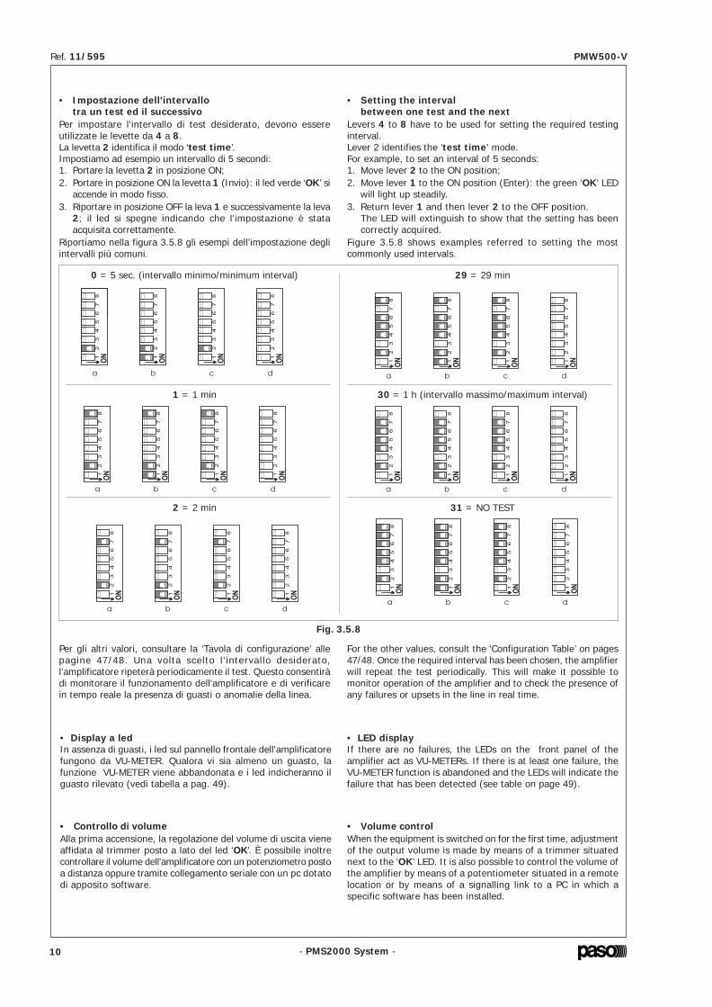
• Impostazione dell'intervallotra un test ed il successivo
Per impostare l'intervallo di test desiderato, devono essereutilizzate le levette da 4 a 8.La levetta 2 identifica il modo ‘test time’.Impostiamo ad esempio un intervallo di 5 secondi:1. Portare la levetta 2 in posizione ON;2. Portare in posizione ON la levetta 1 (Invio): il led verde ‘OK’ si
accende in modo fisso.3. Riportare in posizione OFF la leva 1 e successivamente la leva
2; il led si spegne indicando che l'impostazione è stataacquisita correttamente.
Riportiamo nella figura 3.5.8 gli esempi dell’impostazione degliintervalli più comuni.
0 = 5 sec. (intervallo minimo/minimum interval)
1 = 1 min
29 = 29 min
30 = 1 h (intervallo massimo/maximum interval)
Per gli altri valori, consultare la ‘Tavola di configurazione’ allepagine 47/48. Una volta scelto l' intervallo desiderato,l'amplificatore ripeterà periodicamente il test. Questo consentiràdi monitorare il funzionamento dell'amplificatore e di verificarein tempo reale la presenza di guasti o anomalie della linea.
• Display a ledIn assenza di guasti, i led sul pannello frontale dell'amplificatorefungono da VU-METER. Qualora vi sia almeno un guasto, lafunzione VU-METER viene abbandonata e i led indicheranno ilguasto rilevato (vedi tabella a pag. 49).
Fig. 3.5.8
2 = 2 min 31 = NO TEST
• Controllo di volumeAlla prima accensione, la regolazione del volume di uscita vieneaffidata al trimmer posto a lato del led ‘OK’. È possibile inoltrecontrollare il volume dell'amplificatore con un potenziometro postoa distanza oppure tramite collegamento seriale con un pc dotatodi apposito software.
• Setting the intervalbetween one test and the next
Levers 4 to 8 have to be used for setting the required testinginterval.Lever 2 identifies the ‘test time’ mode.For example, to set an interval of 5 seconds:1. Move lever 2 to the ON position;2. Move lever 1 to the ON position (Enter): the green ‘OK’ LED
will light up steadily.3. Return lever 1 and then lever 2 to the OFF position.
The LED will extinguish to show that the setting has beencorrectly acquired.
Figure 3.5.8 shows examples referred to setting the mostcommonly used intervals.
For the other values, consult the ‘Configuration Table’ on pages47/48. Once the required interval has been chosen, the amplifierwill repeat the test periodically. This will make it possible tomonitor operation of the amplifier and to check the presence ofany failures or upsets in the line in real time.
• LED displayIf there are no failures, the LEDs on the front panel of theamplifier act as VU-METERs. If there is at least one failure, theVU-METER function is abandoned and the LEDs will indicate thefailure that has been detected (see table on page 49).
• Volume controlWhen the equipment is switched on for the first time, adjustmentof the output volume is made by means of a trimmer situatednext to the ‘OK’ LED. It is also possible to control the volume ofthe amplifier by means of a potentiometer situated in a remotelocation or by means of a signalling link to a PC in which aspecific software has been installed.
4. Zet de versterker weer aan en ga na of de groene led ‘OK’gaat branden.
5. Breng hefboom 1 op OFF: de led ‘OK’ gaat uit.6. Breng alle andere hefbomen op de OFF stand.
3.5.3 AfstellenDaar de combinatie kaart-versterker variaties kan veroorzakenin de orde van 5%, kunnen die variaties (maar dit is nietnoodzakelijk) gecorrigeerd worden door het apparaat als volgtaf te stellen:1. Sluit een resistentie van 100 ohm met een adequate
nauwkeurigheid aan op de lijn.2. Zet hefboompjes 2 t/m 8 op de dip-switch op ON, zoals
aangegeven op afbeelding 3.5.15.3. Breng hefboompje 1 op de ON stand om uw keuze te
bevestigen en wacht tot de groene led ‘OK’ gaat branden.4. Breng hefboom 1 weer op OFF.5. Breng alle andere hefboompjes weer op de OFF stand.Met deze handeling brengt het impedantie-meetapparaatabsolute meetwaarden tot stand.
Adrestoekenning • Asignación dirección Afstellen • Calibrado
Afb./Fig. 3.5.14 Afb./Fig. 3.5.15
4. Encender de nuevo el amplificador y comprobar que seencienda el LED verde ‘OK’.
5. Poner de nuevo en la posición OFF la palanca 1: el LED ‘OK’se apaga.
6. Poner de nuevo en la posición OFF todas las otras palancas.
3.5.3 CalibradoDado que la conexión tarjeta-amplificador puede conllevar unasvariaciones de ganancia del orden del 5%, es posible (perono indispensable) corregir dichas variaciones efectuando elcalibrado como sigue:1. Conectar en la línea de salida una resistencia de 100 ohm
de precisión adecuada.2. Maniobrando el dip-switch, llevar en la posición ON las palancas
desde la 2 hasta la 8 como mostrado en la fig. 3.5.15.3. Llevar en la posición ON la palanca 1 para confirmar la
selección y esperar que el LED verde ‘OK’ se encienda.4. Poner de nuevo la palanca 1 en OFF.5. Poner de nuevo en la posición OFF todas las otras palancas.Con esta acción el medidor de impedancia efectúa medidasabsolutas.
10 43
- PMS2000 System -
Ref. 11/595 PMW500-V
- PMS2000 System -
Ref. 11/595 PMW500-V
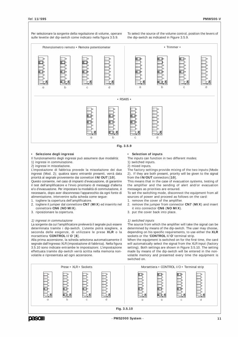
Per selezionare la sorgente della regolazione di volume, operaresulle levette del dip-switch come indicato nella figura 3.5.9.
Potenziometro remoto • Remote potentiometer • Trimmer •
• RS485 •
Fig. 3.5.9
• Selezione degli ingressiIl funzionamento degli ingressi può assumere due modalità:1) ingressi in commutazione.2) ingressi in miscelazione.L’impostazione di fabbrica prevede la miscelazione dei dueingressi (Mod. 2); qualora siano entrambi presenti, verrà datapriorità al segnale proveniente dai connettori IN/OUT [10].Questo consente, nel caso di impianti d’evacuazione, di garantireil test dell’amplificatore e l’invio prioritario di messaggi d’allertae/o d’evacuazione. Per impostare la modalità di commutazione, ènecessario, dopo aver disconnesso l’apparecchio da ogni fonte dialimentazione, intervenire sulla scheda come segue:1. togliere la copertura dell’amplificatore.2. togliere il jumper dal connettore CN7 (MIX) ed inserirlo nel
connettore CN6 (NO MIX).3. riposizionare la copertura.
1) ingressi in commutazioneLa sorgente da cui l’amplificatore preleverà il segnale può esseredeterminata tramite i dip-switch. L’utente potrà scegliere, aseconda delle esigenze, di utilizzare le prese XLR o lamorsettiera ‘CONTROL I/O’ [8].Alla prima accensione, la scheda seleziona automaticamente ilsegnale dall'ingresso XLR (impostazione di fabbrica). Nella figura3.5.10 sono indicate entrambe le impostazioni. L’impostazioneeffettuata tramite dip-switch verrà scritta nella memoria non-volatile e ripresentata ad ogni accensione.
Prese • XLR • Sockets Morsettiera • CONTROL I/O • Terminal strip
Fig. 3.5.10
To select the source of the volume control, position the levers ofthe dip-switch as indicated in Figure 3.5.9.
1) switched inputsThe source from which the amplifier will take the signal can bedetermined by means of the dip-switch. The user may choose,depending on his specific requirements, to use either the XLRsockets or the ‘CONTROL I/O’ terminal strip.When the equipment is switched on for the first time, the cardwill automatically select the signal from the XLR input (factorysetting). Both settings are shown in Figure 3.5.10. The settingmade by means of the dip-switch will be entered in the non-volatile memory and presented every time the equipment isswitched on.
• Selection of inputsThe inputs can function in two different modes:1) switched inputs.2) mixed inputs.The factory settings provide mixing of the two inputs (Mode2). If they are both present, priority will be given to the signalfrom the IN/OUT connectors [10].This means that in the case of evacuation systems, testing ofthe amplifier and the sending of alert and/or evacuationmessages as priorities are ensured.To set the switching mode, disconnect the equipment from allsources of power and proceed as follows on the card:1. remove the cover of the amplifier.2. remove the jumper from connector CN7 (MIX) and insert
it into connector CN6 (NO MIX).3. put the cover back into place.
De selectie van de ingang kan bovendien worden uitgevoerdvia een afstandsschakelaar: hiervoor dient er een schakelaartussen pin 4 en 8 van de connector ‘REMOTE CONTROL’aangesloten te worden, zoals aangegeven op afb. 3.5.11.
Om de ingang met behulp van de afstandsschakelaar te kunnenwijzigen, dient door middel van de dip-switch de XLR ingang teworden geselecteerd.
• Energiebesparende modeDoor het activeren van deze functie blijft de versterker stand-by,en verbruikt zo een minimum aan energie: de led ‘ON’ knippert.Het apparaat gaat weer gewoon werken zodra er een signaalwordt opgevangen bij één van de ingangen.
• ‘LOW CUT’ FilterOm de gesproken tekst beter verstaanbaar te maken, kan wordengekozen voor het inschakelen van een filter voor de lage tonen;de gebruiker dient ook in dat geval de dip-switch te gebruikenvoor het activeren van de functie.
Open = XLRGesloten = Klemmenbord
Abierto = XLRCerrado = Bornera
Afb./Fig. 3.5.11
Filter • ON • Filtro Filter • OFF • Filtro
Afb./Fig. 3.5.12
Low Power • ON Low Power • OFF
Afb./Fig. 3.5.13
B) ‘REMOTE CONTROL’ werking (Afstandsbediening)Voor het besturen door middel van de afstandsbediening wordtverwezen naar de documentatie over de betreffende software.Wanneer het apparaat voor het eerst wordt aangezet, is hetdoor de fabriek ingestelde adres van de kaart gelijk aan 1.
• AdrestoekenningOm het adres te wijzigen handelt u als volgt:1. Schakel de versterker uit.2. Zet met behulp van een potlood het hefboompje 2 en hefboompje
1 op stand ON, zoals aangegeven op afb. 3.5.14a.3. Zodra deze handelingen zijn uitgevoerd gebruikt u hefboompje
3 t/m 8 voor het instellen van het gewenste adres (0 t/m63), aan de hand van de configuratietabel op pag. 47/48.
La selección de la entrada puede ser efectuada tambiénmediante un interruptor remoto: para ello es necesario conectarun interruptor entre los polos 4 y 8 del conectador ‘REMOTECONTROL’ como mostrado en la fig. 3.5.11.
Para poder cambiar la entrada mediante el interruptor remotoes indispensable seleccionar la entrada XLR mediante los dip-switch.
• Filtro ‘LOW CUT’Para mejorar la claridad del habla se puede seleccionar laactivación de un filtro para los tonos graves; el usuario debe ental caso utilizar los dip-switch para activar la función.
• Modalidad de ahorro energéticoActivando esta función el amplificador queda en stand-by,consumiendo de tal manera una cantidad mínima de energía: elLED ‘ON’ destella. La actividad normal es reanudada tan prontoes detectada una señal en una de las dos entradas.
B) Modalidad ‘REMOTE CONTROL’ (Control remoto)Para la gestión mediante el control remoto se remite a ladocumentación de los software correspondientes.Al primer encendido, la configuración de fábrica de la tarjetaprevé que la dirección sea igual que 1.
• Asignación direcciónPara cambiar de dirección, proceder como sigue:1. Apagar el amplificador.2. Con un lápiz llevar en la posición ON la palanca 2 y la palanca
1, como mostrado en la figura 3.5.14a.3. Efectuadas estas operaciones utilizar las palancas desde
la 3 hasta la 8 para configurar la dirección deseada (de0 a 63), conforme a la tabla de configuración de la pág.47/48.
42 11

- PMS2000 System -
Ref. 11/595 PMW500-V
- PMS2000 System -
Ref. 11/595 PMW500-V
La selezione dell'ingresso può essere inoltre essere effettuataattraverso un'interruttore remoto: per fare ciò, è necessariocollegare un interruttore tra i pin 4 e 8 del connettore ‘REMOTECONTROL’ come mostrato in figura 3.5.11.
Per poter cambiare l’ingresso tramite interruttore remoto, èindispensabile selezionare per mezzo dei dip-switch l’ingressoXLR.
• Modalità di risparmio energeticoAttivando questa funzione l’amplificatore rimarrà in stand-by,consumando così una minima quantità di energia: il led ‘ON’lampeggia. La normale attività riprenderà nel momento in cuiverrà rilevato un segnale da uno dei due ingressi.
• Filtro ‘LOW CUT’Ai fini di migliorare l’intelligibilità del parlato, può essere sceltol’inserimento di un filtro per i toni gravi; l’utente dovrà anche inquesto caso utilizzare i dip-switch per attivare la funzione.
Aperto = XLRChiuso = Morsettiera
Opened = XLRClosed = Terminal strip
Fig. 3.5.11
Filtro • ON • Filter Filtro • OFF • Filter
Fig. 3.5.12
Low Power • ON Low Power • OFF
Fig. 3.5.13
B) Modalità ‘REMOTE CONTROL’ (Controllo remoto)Per la gestione tramite il controllo remoto, si rimanda alladocumentazione dei software relativi. Alla prima accensione,l'impostazione di fabbrica della scheda prevede che l'indirizzosia uguale a 1.
• Impostazione indirizzoPer cambiare indirizzo, procedere come segue:1. Spegnere l'amplificatore.2. Con l'aiuto di un matita, portare in posizione ON la levetta 1
e la levetta 2 come indicato in figura 3.5.14a.3. Effettuate queste operazioni utilizzare le levette da 3 a 8 per
impostare l'indirizzo desiderato (da 0 a 63), seguendo la tavoladi configurazione alle pagine 47/48.
The input can also be selected by means of a remote switch. Inorder to be able to do this, it is necessary to connect a switchbetween pins 4 and 8 of the ‘REMOTE CONTROL’ connector, asshown in Fig. 3.5.11.
In order to be able to change the input by means of the remoteswitch, it is essential to select the XLR input by means of thedip-switch.
• ‘LOW CUT’ FilterFor the purpose of improving the speech intelligibility, it is possibleto choose to include a filter for the bass tones. Again in this casethe user will have to use the dip-switch to activate the function.
• Energy-saving modeIf this function is activated, the amplifier will remain on stand-by, so that it will only use up a minimum quantity of power. The‘ON’ LED will flash. Normal activity will be resumed as soon as asignal on either of the two inputs is detected.
B) ‘REMOTE CONTROL’ modeFor management via a remote control, reference should be madeto the documentation concerning the software being used. Onswitching on the equipment for the first time, the address will beequal to 1 according to the factory setting of the card.
• Address assignmentTo change this address, proceed as follows:1. Switch off the amplifier.2. With the help of a pencil, move lever 1 and lever 2 to the
ON position as indicated in Figure 3.5.14a.3. Carry out these operations using levers from 3 to 8 to set
the required address (from 0 to 63), on the basis of theconfiguration table on pages 47/48.
Om de bron van de volumeregeling te selecteren, dienen dehefbomen van de dip-switch gebruikt te worden, zoalsaangegeven op afbeelding 3.5.9.
Potentiometer op afstand • Potenciómetro remoto • Trimmer •
• RS485 •
Afb./Fig. 3.5.9
• Selectie van ingangenDe ingangen kunnen op twee manieren functioneren:1) als geschakelde ingangen2) als gemengde ingangenIn de fabriek worden de twee ingangen in de gemengde modusingesteld (Mod. 2); indien ze beide aanwezig zijn, krijgt hetsignaal afkomstig uit de connectors IN/OUT [10] voorrang.Hierdoor is men, in het geval van ontruimingsinstallaties,verzekerd van de test van de versterker en de prioritaireverzending van alert- en/of ontruimingsberichten.Het instellen van de geschakelde modus dient, nadat hetapparaat is losgekoppeld van alle voedingsbronnen, plaats tevinden met behulp van de kaart en wel als volgt:1. verwijder het deksel van de versterker2. verwijder de jumper uit de connector CN7 (MIX) en steek
deze in connector CN6 (NO MIX).3. plaats het deksel terug.
1) als geschakelde ingangenDe bron van waaruit de versterker het signaal haalt kan wordenvastgesteld met behulp van de dip-switch. De gebruiker kan,naar gelang de behoefte, kiezen om de XLR bussen te gebruikenof de klemmenstrook CONTROL I/O. Wanneer het apparaatvoor het eerst wordt aangezet, selecteert de kaart automatischhet signaal van de XLR ingang (fabrieksinstelling). In afbeelding3.5.10 worden beide instellingen aangegeven. De met behulpvan de dip-switch tot stand gebrachte instelling wordtopgenomen in het niet-vluchtige geheugen en komt bij elkeaanschakeling weer terug.
Bussen • XLR • Tomas Klemmenbord • CONTROL I/O • Bornera
Afb./Fig. 3.5.10
Para seleccionar la fuente de la regulación de volumen, maniobrarlas palancas del dip-switch como indicado en la figura 3.5.9.
1) entradas en conmutaciónLa fuente de la cual el amplificador tomará la señal se puededeterminar mediante los dip-switch. El usuario puede elegir,según las exigencias, entre utilizar las tomas XLR o elterminal de conexión CONTROL I/O. Al primer encendido,la tarjeta selecciona automáticamente la señal de la entradaXLR (configuración de fábrica).En la figura 3.5.10 se muestran ambas configuraciones.La configuración efectuada mediante dip-switch es escritaen la memoria no-volátil y es reactivada a cada encendido.
• Selección de las entradasEl funcionamiento de las entradas puede asumir dosmodalidades:1) entradas en conmutación2) entradas en mezclaEl ajuste de fábrica prevé la mezcla de las dos entradas (Mod.2); si están presentes ambas, se da la prioridad a la señalprocedentes de los conectores IN/OUT [10]. Esto permite,en el caso de instalaciones de evacuación, garantizar el testdel amplificador y el envío prioritario de mensajes de alerta y/o de evacuación. Para programar la modalidad de conmutaciónes necesario, después de haber desconectado el aparato decualquier fuente de alimentación, actuar sobre la tarjeta comosigue:1. quitar la tapa del amplificador2. quitar el puente del conector CN7 (MIX) y ponerlo en el
conector CN6 (NO MIX).3. poner de nuevo la tapa en su sitio.
12 41

- PMS2000 System -
Ref. 11/595 PMW500-V
- PMS2000 System -
Ref. 11/595 PMW500-V
4. Riaccendere l'amplificatore e verificare che si accenda il ledverde ‘OK’.
5. Riportare in posizione OFF la leva 1: il led ‘OK’ si spegne.
6. Riportare in posizione OFF tutte le altre leve.
3.5.3 CalibrazionePoichè l'accoppiamento scheda-amplificatore può portare dellevariazioni di guadagno nell'ordine del 5%, è possibile (ma nonindispensabile) correggere tali variazioni effettuando lacalibrazione nel seguente modo:1. Collegare sulla linea di uscita una resistenza da 100 ohm di
adeguata precisione.2. Agendo sul dip-switch, portare in posizione ON le levette da
2 a 8 come indicato in figura 3.5.15.3. Portare in posizione ON la levetta 1 per confermare la scelta
ed attendere che il led verde ‘OK’ si accenda.4. Riposizionare la leva 1 su OFF.5. Riportare tutte le altre leve in posizione OFF.Con questa azione, il misuratore di impedenza effettuerà misureassolute.
Impostazione indirizzo • Address setting Calibrazione • Calibration
Fig. 3.5.14 Fig. 3.5.15
4. Switch the amplifier on again and check that the green ‘OK’LED lights up.
5. Return lever 1 to the OFF position: the ‘OK’ LED will extinguish.6. Return all the other levers to the OFF position.
3.5.3 CalibrationSince the amplifier-card connection may lead to variations ingain of the order of 5%, it is possible (but not essential) tocorrect these variations by carrying out a calibration as follows:1. Connect a suitably accurate 100 ohm resistor on the output
line.2. On the dip-switch, move levers from 2 to 8 to the ON
position, as shown in Figure 3.5.15.3. Move lever 1 to the ON position to confirm the choice and
wait for the green ‘OK’ LED to light up.4. Return lever 1 to the OFF position.5. Return all the other levers to the OFF position.After doing this, the impedance measurement device will carryout absolute measurements.
• Instelling van eeninterval tussen twee tests in
Om het gewenste testinterval in te stellen dienen de hefboompjes4 t/m 8 gebruikt te worden.Hefboom 2 geeft de ‘test time’ mode aan.Laten we bijvoorbeeld een interval van 5 seconden instellen:1. Breng hefboom 2 op stand ON;2. Breng hefboom 1 op stand ON (Start): de groene led ‘OK’
gaat blijvend branden.3. Breng hefboom 1 weer terug naar stand OFF en vervolgens
ook hefboom 2; de led houdt op met branden om aan te gevendat de instelling correct is uitgevoerd.
In afbeelding 3.5.8 staan de voorbeelden van de instelling vande meest voorkomende intervals.
0 = 5 sec. (min. interval/intervalo mínimo)
1 = 1 min
29 = 29 min
30 = 1 h (max. interval/intervalo máximo)
Raadpleeg voor de overige waarden de ‘Configuratietafel’ oppag. 47/48. Wanneer het gewenste interval is gekozen, herhaaltde versterker regelmatig de test. Hierdoor is het mogelijk omde werking van de versterker te bewaken en onmiddellijk na tegaan of er defecten of storingen op de lijn zijn.
• Display met led’sAls er geen storingen zijn, hebben de led’s op het frontpaneelvan de versterker de functie van VU-METER. In het geval vanten minste één storing, wordt de VU-METER-functie verlaten enwordt de opgespoorde storing door de led’s aangegeven (zietabel op pag. 49).
Fig. 3.5.8
2 = 2 min 31 = NO TEST
• Instelling geluidsvolumeWanneer het apparaat voor het eerst wordt aangezet, wordtde uitgangsvolumeregeling overgelaten aan de trimmer naastde led ‘OK’. Bovendien kan het volume van de versterker ookworden geregeld met een op afstand geplaatste potentiometer,of door middel van een seriële aansluiting met een van speciaalsoftware voorziene PC.
• Configuración delintervalo entre un test y el siguiente
Para configurar el intervalo de test deseado se deben utilizar laspalancas desde la 4 hasta la 8.La palanca 2 identifica el modo ‘test time’.Configurar por ejemplo un intervalo de 5 segundos:1. Poner la palanca 2 en la posición ON;2. Poner en la posición ON la palanca 1 (Intro): el LED verde
‘OK’ se enciende fijo.3. Poner de nuevo en la OFF la palanca 1 y seguidamente la
palanca 2; el LED se apaga para indicar que la configuraciónha sido adquirida correctamente.
En la figura 3.5.8 se muestran los ejemplos de configuración delos intervalos más comunes.
Para los otros valores consultar la ‘Tabla de configuración’ en lapág. 47/48. Una vez seleccionado el intervalo deseado, elamplificador repite periódicamente el test. Esto consentirámonitorizar el funcionamiento del amplificador y verificar entiempo real la presencia de averías o anomalías de la línea.
• Display de LEDsNo habiendo averías, los LEDs en el panel frontal del amplificadorhacen de VU-METER. Cuando hay por lo menos una avería, esabandonada la función VU-METER y los LEDs indican la averíaregistrada (ver la tabla en la pág. 49).
• Control de volumenAl primer encendido, la regulación del volumen de salida esconfiada al condensador de ajuste situado al lado del LED‘OK’. Es posible también controlar el volumen del amplificadorcon un potenciómetro situado a distancia o bien medianteenlace serie con un PC provisto del software correspondiente.
40 13

- PMS2000 System -
Ref. 11/595 PMW500-V
- PMS2000 System -
Ref. 11/595 PMW500-V
4. USO DELL’APPARECCHIO4.1 AccensionePrima di mettere in funzione l’apparecchio accertarsi di averrealizzato tutte le connessioni necessarie al completamentodell’impianto. Portare l’interruttore di rete [4] in posizione ON.La spia luminosa ‘ON’ [2] confermerà l’accensione delloapparecchio.
4.2 DisplayI led [3] del pannello frontale, ad esclusione di quello relativoall’accensione dell’apparecchio [2] fungono da indicatori dellivello di uscita e/o da indicatori dello stato di funzionamentodell’amplificatore (vedi par. ‘Display a led’. pagina 10).
5. NOTE DI SERVIZIO5.1 Ventilazione forzataL’unità di potenza PMW500-V dispone di due ventole per ilraffreddamento forzato degli stadi finali di potenza e dell’internodell’apparecchio. Queste ventole, asservite da un proprio circuitodi alimentazione e controllo, si attivano automaticamente alraggiungimento di una determinata temperatura del dissipatoredi calore e si arrestano quando la temperatura ritorna a livellinormali. In pratica, in condizioni d’uso tipiche per amplificatoridi questa caratura, quali la diffusione di musica di sottofondointervallata da annunci vocali a piena potenza, ed in condizioniclimatiche normali, la ventilazione forzata non si rendenecessaria e non viene quindi attivata; ciò comporta unanotevole riduzione dell’usura meccanica delle parti in movimento,la riduzione dell’accumulo di polvere introdotta nell’apparecchiodalle ventole e, non ultimo, la riduzione del rumore ambientalecausato dall’elevato numero di ventole in rotazione nel caso diimpianti con uno o più armadi contenenti un gran numero dibooster. Le ventole aspirano aria fresca dalle feritoie posterioridell’apparecchio [9] ed espellono l’aria riscaldata dalle feritoieanteriori [1], pertanto, è indispensabile che le feritoie nonvengano in alcun modo ostruite.
5.2 Condizioni di sovreccarico e protezioniIl modello PMW500-V dispone, oltre alla protezione classicaofferta dai fusibili, di una protezione elettronica e di una termicache lo salvaguarda da eventuali rischi di danneggiamento.Applicare un valore di impedenza di carico inferiore a quellanominale significa richiedere all’apparecchio una potenzasuperiore a quella erogabile con continuità.Questo potrebbe portare al danneggiamento degli stadi finali dipotenza e del trasformatore di uscita.Per non incorrere in questi inconvenienti l’amplificatore del sistemamodulare sono dotati di circuito di protezione contro i sovraccarichicon ripristino automatico. Il circuito di protezione interverràimmediatamente sull’amplificatore qualora si verificasse uno deiseguenti casi:- cortocircuito su una delle uscite per altoparlanti.- impedenza di carico inferiore al 50% del valore nominale.- potenza richiesta dal sistema di diffusori, collegati sulle linee
a tensione costante, superiore a quella erogabiledall’amplificatore.
La condizione di sovraccarico é segnalata dall’accensione,intermittente, della spia luminosa ‘OVD’ [3] posta sul pannellofrontale dell’apparecchio. L’apparecchio riprenderà il regolarefunzionamento non appena si sarà provveduto a rimuovere lacausa del sovraccarico. La protezione termica, anch’essa di tipoautoripristinante, interviene nel caso che l’apparecchio raggiungauna temperatura eccessiva dovuta, per esempio, ad unatemperatura ambiente troppo elevata o ad una scarsa aerazionedell’armadio rack.Durante l’intervento della protezione termica l’amplificatoresmetterà di funzionare, tutti i led si spegneranno e rimarranno infunzione soltanto le ventole.
4. USING THE EQUIPMENT4.1 Switching onBefore starting up the equipment, make sure that all theappropriate connections have been made to complete thesystem. Position the main power switch [4] in the ON position.The ‘ON’ [2] signalling lamp will confirm that the equipmenthas been switched on.
4.2 DisplayWith the exception of the LED indicating the on or off status ofthe equipment [2], the LEDs [3] on the front panel can act asindicators of the output level and/or of the operating status ofthe amplifier (see point ‘LED display’ on page 10).
5. SERVICE NOTES5.1 Forced ventilationModel PMW500-V boosters have a fan for the forced coolingof the final power stages and of the inside of the equipment.This fan, controlled by its own power-supply and control circuit,is activated automatically when the heat-sink reaches a giventemperature and turns off once the temperature has returnedto the normal level. In practice, in typical conditions of use foramplifiers of this size, such as the broadcasting of backgroundmusic with full-power voice announcement at intervals, andin normal climatic conditions, forced ventilation is not necessaryand will therefore not be activated. This leads to a considerablereduction in the mechanical wear rate of the moving parts, areduction in the accumulation of dust introduced inside theequipment by the fan and, last but not least, a reduction inthe environmental noise caused by the high number of fansthat would be running in case of systems with one or morecabinets containing a large number of boosters.The fan takes in cool air through the slits on the rear of theequipment [9] and expels the heated air through the slits infront [1]. It is therefore essential that these slits should notbe obstructed in any way.
5.2 Overload conditions and protection devicesIn addition to the usual protection consisting of fuses, thePMW500-V boosters have an electronic protection device anda thermal protection device in order to safeguard them frompossible risks of damage. Applying a lower loading impedancethan the rated value means requiring the equipment to supplya power higher than it can do on a continuous basis.This could cause damage to the final power stages and to theoutput transformer.In order to avoid these problems, the amplifiers of the modularsystem are equipped with protection circuits against overloads,with automatic reinstatement.The protection circuit will be tripped immediately on the amplifierif any of the following cases occurs:- short circuit on one of the loudspeaker outputs;- loading impedance less than 50% of the rated value;- power required of the loudspeaker system connected to
the constant-voltage lines higher than the power that theamplifier is able to deliver.
Overload conditions are signalled by the fact that the ‘OVD’signalling lamp [3] located on the front panel of the equipmentwill start to flash. The equipment will resume normal operationas soon as the cause of the overload has been eliminated.The thermal protection is also of the self-resetting type, andis tripped when the equipment reaches an excessively hightemperature. This may be due, for example, to the fact thatthe ambient temperature is too high or to the insufficientventilation of the rack cabinet.When the thermal protection is tripped, the amplifier will stopworking, all the LED's will extinguish and only the fan willcontinue to run.
• Connector ‘REMOTE CONTROL’Deze connector dient voor de aansluiting van de versterkerop een personal computer gebruikt te worden.
3.5.2 WerkwijzeMet de PM2092-V kaart zijn de volgende werkwijzen mogelijk:• ‘STAND-ALONE’ werking;• ‘REMOTE CONTROL’ werking (Afstandsbediening).In de volgende paragrafen worden alle instellingen enwijzigingen aangegeven, die in beide gevallen op de kaart vantoepassing zijn.
A) ‘STAND-ALONE’ werkingIn dit geval dienen er enkele parameters ingesteld te wordenmet behulp van de speciale, op de achterzijde van de versterkeraangebrachte dip-switch ‘MODE SEL.’.OPMERKING: het hefboompje 1 van de dip-switch heeft een‘Start’ functie: het dient dus gebruikt te worden om de met deandere hefbomen uitgevoerde keuzes te bevestigen.
Pin Beschrijving1 24V externe voeding (optional)2 24V externe voeding (optional)3 massa4 selectie ingangen5 RS485 +6 24V externe voeding (optional)7 massa8 massa9 RS485 –
Zodra deze aansluiting is uitgevoerd, kan metbehulp van speciale software de PM2092-Vkaart bestuurd worden.In de onderstaande tabel is de pinconfiguratievan de connector weergegeven.
• Afstemming van installatieZodra de luidsprekerslijn eenmaal geïnstalleerd is en deversterker volgens de aanwijzignen in het hoofdstuk‘Aansluitingen’ aangesloten, dient de versterker op de ingebruik zijnde impedantie te worden afgestemd. Dieimpedantie geldt als referentie voor al le toekomstigemetingen. Indien de metingen hoger zijn dan ± 20% vanhet referentiegegeven, wordt de opgespoorde storing via deled door de versterker gesignaleerd.Voor het verkrijgen vande referentie-impedantie dient u als volgt te handelen:1. Zet de versterker aan.2. Werk nu op de dip-switch en zet het hefboompje 8 op ON en
vervolgens hefboompje 1 zoals aangegeven op afbeelding 3.5.7.
De groene led ‘OK’ gaat tweemaal knipperen en na enigeseconden blijft deze branden, waarmee de juiste afstemmingvan de lijn wordt bevestigd.3. Breng hefboom 1 en hefboom 8 op stand OFF: de groene led
houdt op met branden.
Afb./Fig. 3.5.6
Afb./Fig. 3.5.7
• Conectador ‘REMOTE CONTROL’Este conectador debe ser utilizado para la conexión delamplificador a un ordenador personal.
Una vez efectuada esta conexión será posiblecontrolar la tarjeta PM2092-V mediantesoftware dedicado.En la tabla siguiente se indican los polos delconectador.
Polo Descripción1 alimentación externa 24V (opción)2 alimentación externa 24V (opción)3 masa4 selección entradas5 RS485 +6 alimentación externa 24V (opción)7 masa8 masa9 RS485 –
3.5.2 Modalidades de funcionamientoLas modalidades de funcionamiento consentidas por la tarjetaPM2092-V son dos:• Modalidad ‘STAND-ALONE’;• Modalidad ‘REMOTE CONTROL’ (Control remoto).En los párrafos siguientes se muestran todas las configuracionesy modificaciones que se pueden aplicar a la tarjeta en ambasmodalidades de uso.
A) Modalidad ‘STAND-ALONE’En esta modalidad es necesario configurar algunos parámetrosmediante el dip-switch correspondiente ‘MODE SEL.’ presenteen la parte trasera del amplificador.NOTA: la palanca 1 del dip-switch tiene la función de ‘Intro’: esdecir que debe ser utilizada para confirmar las seleccionesefectuadas con las otras palancas.
• Adquisición de la instalaciónUna vez instalada de manera definitiva la línea de altavoces yconectado el amplificador como indicado en el capítulo‘Conexiones’, es necesario que el amplificador adquiera laimpedancia corriente. Dicha impedancia será tomada comoreferencia para las medidas futuras. Si las medidas sobrepasanel ± 20% de la medida de referencia, el amplificador señalará,mediante LED, la anomalía detectada.Para adquirir la impedancia de referencia, proceder comosigue:1. Encender el amplificador.2. Maniobrar el dip-switch llevando en la posición ON la palanca
8 y seguidamente la palanca 1 como indicado en la fig. 3.5.7.
El LED verde ‘OK’ destellará dos veces y al cabo de unossegundos quedará encendido fijo para indicar la correctaadquisición de la línea.3. Poner de nuevo la palanca 1 y la palanca 8 en la posición
OFF: el LED verde se apagará.
14 39

- PMS2000 System -
Ref. 11/595 PMW500-V
- PMS2000 System -
Ref. 11/595 PMW500-V
5.3 TaratureQuesta operazione può essere effettuata solo dapersonale tecnico qualificato munito di appropriateapparecchiature.La taratura è necessaria esclusivamente in seguito ad unariparazione degli stadi di amplificazione interessati, ad esempio,in caso di sostituzione di uno o più transistor finali.1- Regolare P101 (con dissipatore a temperatura ambiente) fino
a misurare una tensione di 6 mV ai capi di R110.2- Regolare P151 (con dissipatore a temperatura ambiente) fino
a misurare una tensione di 6 mV ai capi di R160.
5.3 AdjustmentsThis operation can only be carried out by qualifiedtechnical personnel using the appropriate equipment.
Calibration will only be necessary following repair of the amplifierstages concerned, for example in the event of replacement ofone or more final transistors.1- Adjust P101 (with ambient temperature heat sink) until a
voltage of 6 mV is measured at the ends of R110.2- Adjust P151 (with ambient temperature heat sink) until a
voltage of 6 mV is measured at the ends of R160.
6. CARATTERISTICHE TECNICHE 6. TECHNICAL SPECIFICATIONS
Potenza di uscita nom inale 500 W Nom inal power
Uscita a tensione costante 100, 70, 50, 90 V(20, 9.4, 5, 16 Ω) Constant vo ltage outputs
Distorsione alla potenza nom inale < 1% Distorsion at rated power
Frequenza di taglio del filtro (Low Cut) 320 Hz ± 20 Hz Cut-off frequency of the filter (Low Cut)
Vmax relè 100 V Relay Vm ax
Soglia di attivazione (m od. Low Power) ~ 55 mV A ctivation threshold (Low Power mode)
Soglia d i lettura 20 kHz (ingresso) ~ 30 mV Reading threshold (input)
C OMU NIC A ZIONE SER IA LE • R S485 • SER IA L C OMM U NIC A T ION
Velocità 19200 bit/s Speed
Modalità di trasm issione 8 bit Transm ission mode
Bit di parità no Parity bit
Stop bit 1 Stop bit
INGRESSI XLR • XLR INPUT S
Sensib ilità / impedenza 775 mV 100 kΩ Sensitivity/impedance
Rapporto segnale/disturbo > 80 dB S/N ratio
Risposta in frequenza 50 ÷ 20000 Hz (0/-3 dB) Frequency Response
INGRESSO MORSET T IERA • T ERMINA L ST RIP INPUT
Sensib ilità / impedenza 720 mV 100 kΩ Sensitivity/impedance
Rapporto segnale/disturbo > 80 dB S/N ratio
Risposta in frequenza 50 ÷ 20000 Hz (0/-3 dB) Frequency Response
CONDIZIONI DI FUNZIONA MENT O • OPERA T ING CONDIT IONS
A limentazione da rete 230 V ± 10% 50 / 60 Hz Mains power supply
Consumo di potenza (@ 230 Vca) 950 W / 1150 VA Power consumption (@ 230 VA C)
A limentazione esterna in c.c. 22 ÷ 28 V External DC power supply
Consumo di corrente (@ 22÷28 Vcc) 25 A (MA X) Current consumption (@ 22÷28 VDC)
Dimensioni 482 x 133 x 420 mm Dimensions
Peso 25 kg Weight
Temperatura operativa /Temperatura di stoccaggio
-10°C ÷ +45°C-40°C ÷ +70°C
Operating temperature range /Storage temperature range
Um idità relativa < 90 % Relative hum idity
Sicurezza secondo norma CEI EN 60065 Safety according to
• Aansluiting ingangen (optie)Indien men een tweede ingang wenst aan te sluiten, dienen deklemmen 8, 9 e 10 van de klemmenstrook ‘CONTROL I/O’ [8]gebruikt te worden, zoals aangegeven op afbeelding 3.5.2.
• Potentiometer metafstandsbediening
De potentiometer met afstands-bediening moet worden aangeslotenop de klemmen 6, 7 en 8 van deklemmenstrook ‘CONTROL I/O’ [8].
Zie afb. 3.5.5 voor het verhogen ofverlagen van het geluidsvolume.
Afb./Fig. 3.5.5
• Aansluiting op de luidsprekerslijnSluit klem 1 van de klemmenstrook ‘CONTROL I/O’ aan op de100 V vermogensuitgang. De luidsprekerslijn moet daarentegenop klem 2 worden aangesloten (zie afb. 3.3.3, pag. 36).
Afb./Fig. 3.5.2
C
O
N
T
R
O
L
I
/
OTO SPEAKER LINE
TO POWER OUTPUT
RELAY
NORMAL OPEN
COMMON
NORMAL CLOSED
V max 100V
I max 3A
IN +INPUT
LINE
IN -10
9
1
2
8
7
6
5
4
3
REMOTE VOL.
min. 10K LIN.
IN –
IN +C
O
N
T
R
O
L
I
/
OTO SPEAKER LINE
TO POWER OUTPUT
RELAY
NORMAL OPEN
COMMON
NORMAL CLOSED
V max 100V
I max 3A
IN +INPUT
LINE
IN -10
9
1
2
8
7
6
5
4
3
REMOTE VOL.
min. 10K LIN.
• Aansluiting relaisZoals te zien is op het achterpaneel van de versterker, zijn derelaisaansluitingen zoals aangegeven op afbeelding 3.5.3.
• Werking van het relaisHet relais kent drie werkingsmodi. Bij de eerste modus (MODE0 - fabrieksinstelling) is het relais altijd bekrachtigd en wordthet uitsluitend gedeactiveerd als er geen voeding is of wanneerde versterker stuk is. In deze modus is het mogelijk om, metbehulp van de kaart PM2095, een systeem met meerdereversterkers in te stellen, met automatische inschakeling vanéén of meer reserveversterkers. Bij de tweede modus (MODE1) is het relais altijd bekrachtigd en het wordt het uitsluitendgedeactiveerd wanneer er een defect is op de luidsprekerlijn.Bij de derde modus (MODE 2) is het relais altijd bekrachtigden wordt het gedeactiveerd wanneer de lijn of de versterkerstuk is.
• Werkingsmodus van het relaisHieronder volgt een beschrijving van de procedure die gevolgdmoet worden om de verschillende modi in te stellen middels dedip-switch van de kaart. De hendels moeten achtereenvolgens(niet tegelijkertijd) omlaag gezet worden.
Afb./Fig. 3.5.3
d
51
23
4
ON
67
8
a
51
23
4
ON
67
8
b
51
23
4
ON
67
8
c
51
23
4
ON
67
8
MODE 0
da
51
23
4
ON
67
8
b
51
23
4
ON
67
8
c
51
23
4
ON
67
8
51
23
4
ON
67
8
MODE 1
da
51
23
4
ON
67
8
b
51
23
4
ON
67
8
c
51
23
4
ON
67
8
51
23
4
ON
67
8
MODE 2
C
O
N
T
R
O
L
I
/
OTO SPEAKER LINE
TO POWER OUTPUT
RELAY
NORMAL OPEN
COMMON
NORMAL CLOSED
V max 100V
I max 3A
IN +INPUT
LINE
IN -10
9
1
2
8
7
6
5
4
3
REMOTE VOL.
min. 10K LIN.
Volume
–
Volume
+
Afb./Fig. 3.5.4
• Conexión entradas (opción)Si se desea conectar una segunda entrada, utilizar los terminales8, 9 y 10 de la bornera de conexión ‘CONTROL I/O’ comomostrado en la figura 3.5.2.
• Conexión a la línea altavocesConectar el terminal 1 de la bornera ‘CONTROL I/O’a la salidade potencia 100 V. La línea altavoces se debe conectar al terminal2 (ver figura 3.3.3, pág 36).
• Conexión reléComo indicado en el panel trasero del amplificador, lasconexiones del relé son las mostradas en la figura 3.5.3.
• Funcionamiento del reléLas modalidades de funcionamiento del relé son tres.La primera (MODE 0 - configuración de fábrica) prevé que elrelé esté siempre excitado y se desexcita sólo por falta dealimentación o avería del amplificador. En esta modalidad esposible, utilizando la tarjeta PM2095, configurar un sistemade varios amplificadores con la activación automática de unao más reservas. En la segunda modalidad (MODE 1) el reléestá siempre excitado y se desexcita sólo ante una avería enla línea de los altavoces.En la tercera modalidad (MODE 2) el relé está siempreexcitado y se desexcita si hay una avería en la línea o en elamplificador.
• Modalidad de funcionamiento del reléA continuación se presenta la secuencia a efectuar paraconfigurar las distintas modalidades trámite el dip-switch dela tarjeta. Las palancas se deben bajar de manera secuencial(no simultánea).
• Potenciómetro remotoEl potenciómetro remoto se debeconectar a los terminales 6, 7 y 8 dela bornera de conexión ‘CONTROL I/O’ [8].
Hacer referencia a la fig. 3.5.5 paraaumentar o reducir el volumen.
38 15

- PMS2000 System -
Ref. 11/595 PMW500-V
- PMS2000 System -
Ref. 11/595 PMW500-V
8. LISTA DELLE PARTI DI RICAMBIO
Pannello frontale serigrafato 36/2481-S1 Silk-screen printed front panel
A ssieme circuito di potenza (SX) 27/4253 Power circuit assembly (left)
A ssieme circuito di potenza (DX) 27/4254 Power circuit assembly (right)
A ssieme circuito scheda controllo 27/4340-V Control card circuit assembly
Assieme circuito limitatore di corrente 27/4356 Current limiter circuit assembly
Assieme circuito Vu-Meter 27/4370 Circuit assembly Vu-Meter
Assieme circuito comandi e pilotaggio 27/4575 Control and driving circuit assembly
Trasformatore d’alimentazione TF197 Power-supply transformer
Trasformatore d’uscita TU138/16 Output transformer
Micro programmato 01PMW1.2 Programmed micro
Interruttore di rete 19/113 Mains switch
Maniglia 38/341-VNO Handle
Ventola di raffreddamento VT7 Cooling fan
Ponte raddrizzatore 50 A – 200 V 16/73 50 A – 200 V rectifier bridge
Condensatore elettrolitico 10000µF 63V 649060103 10000µF 63V electrolytic capacitor
Condensatore ceramico 2,2 nF 400V 709010222 2.2 nF 400V ceramic capacitor
Transistor TIP35 17/79 Transistor TIP35
Transistor BD911 17/65 Transistor BD911
7. ACCESSORI
Scheda traslatore di linea ............................................. TM92
7. ACCESSORIES
Line transformer card .................................................... TM92
8. LIST OF SPARE PARTS
3.4 Kaart lijntransformatorVoor het installeren van dit hulpstuk moet eerst het deksel vanhet apparaat worden verwijderd. Zodra de connector CN204(detail [A], afb. 3.4.1) is geïdentificeerd,moeten de daarin bevestigdekortsluitbruggen worden verwijderd endaarvoor in de plaats de kaart TM92worden ingestoken.
Sluit de eenheid door het deksel weerterug te plaatsen.
Afb./Fig. 3.4.1
Afb./Fig. 3.5.1
3.5.1 AansluitingenDe klemmenstrook ‘CONTROL I/O’ [8]die zich op het achterpaneel van deversterker bevindt, dient gebruikt teworden voor het tot stand brengen vande hoofdaansluit ingen van dePM2092-V kaart.
3.5 BesturingskaartIn het binnenste van de versterker wordt standaard debesturingskaart PM2092-V geïnstalleerd, speciaal ontworpenom de versterker zelf en de versterkerslijn(en) eenvoudig ensnel te kunnen testen met behulp van de kaarten PM2094-V.Deze kaart bestuurt alle functies van de versterker, van deingangen tot de diagnostiek, en kan de volgende functiesuitvoeren:• impedantiemetingen van de lijn;• diagnostiek van de versterker;• controle van de goede staat van de versterkerslijn.• controle aardingsisolatie (GND FAULT);• geluidsvolumecontrole;• selectie van twee ingangen;• controle van het vermogensrelais;• mogelijkheid om LOW CUT filter in te schakelen;• energiebesparende werking ‘LOW POWER’.De kaart kan bovendien door middel van een seriële interfacebestuurd worden. Niet alleen alle lokaal met de dip-switchingestelde handelingen en/of controles worden uitgevoerd, maarook is het mogelijk alle parameters weer te geven en te wijzigen,onder andere:• aflezen van de referentie-impedantie voor de tests;• minimum- en maximumwaarde waarbinnen de test geldig is;• aflezen van teststatus;• ingangstest;• temperatuurmeting van eindtransistoren;• regeling geluidsvolume;• afstandsbediening van het relais.
C
O
N
T
R
O
L
I
/
OTO SPEAKER LINE
TO POWER OUTPUT
RELAY
NORMAL OPEN
COMMON
NORMAL CLOSED
V max 100V
I max 3A
IN +INPUT
LINE
IN -10
9
1
2
8
7
6
5
4
3
REMOTE VOL.
min. 10K LIN.
Aantal luidsprekers =833 Ω20 Ω
= 41
Voorbeeld: er wordt een PMW500-V versterker gebruikt metluidsprekers met een nominale impedantie van 833 ohm (ditkomt overeen met een vermogen van 12W op 100 volt lijn). Uittabel 3.3.1 kan men afleiden dat de nominale impedantie van de100 volt uitgangslijn 20 ohm bedraagt. Dus:
Ejemplo: se emplea un amplificador PMW500-V con difusoresque tienen una impedancia nominal de 833 ohm(correspondientes a una potencia de 12 W en línea de 100 V).De la tabla 3.3.1 se saca que la impedancia nominal de la líneade salida de 100 V es de 20 ohm. Por lo tanto:
Número de difusores =833 Ω20 Ω
= 41
3.4 Tarjeta transformador de líneaPara instalar este accesorio es necesario quitar la tapa delaparato. Después de haber identificado al conector CN204
(elemento [A], fig. 3.4.1) es precisoquitar los puentes de cortocircuitopuestos en él y colocar, en su lugar, latarjeta TM92.
Cerrar la unidad poniendo la tapa en susitio.
3.5 Tarjeta de controlDentro del amplificador en la fábrica se monta la tarjeta de controlPM2092-V, que ha sido creada para consentir la ejecución,simple y rápida, de pruebas del propio amplificador, como tambiénde la/las líneas de altavoces utilizando la tarjeta PM2094-V.Esta tarjeta gestiona todas las funciones amplificador, desdelas entradas al diagnóstico, y realiza las siguientes funciones:• medidas de impedancia de línea;• diagnóstico del amplificador;• comprobación de la integridad de la línea de altavoces.• verificación del aislamiento de tierra (GND FAULT);• control de volumen;• selección de dos entradas;• control del relé de potencia;• posibilidad de activación del filtro LOW CUT;• modalidad de ahorro energético ‘LOW POWER’.La tarjeta también se puede controlar mediante interfaz serie.Además de efectuar todas las operaciones y/o verificacionesconfiguradas localmente con los dip-switch, es posible visualizary modificar todos los parámetros entre los cuales:• lectura de la impedancia de referencia para el test;• valor mínimo y máximo dentro de los cuales el test es válido;• lectura del estado de los test;• test de la entrada;• medida de la temperatura de los transistores finales;• regulación del volumen;• comando remoto del relé.
3.5.1 ConexiónesEl terminal de conexión ‘CONTROLI/O’ [8] presente en el panel traserodel amplificador se debe utilizar paraefectuar las conexiones principales de latarjeta PM2092-V.
CI202
R2
32
R2
30
CN
20
4
C218
R2
29
R2
16
R2
33
R2
27
C2
20
R2
31
R2
08
D2
19
R226 C217
X2
07
R2
28
C219
CN
20
3C
N2
02
C221
PR201PR202
R
X208
A
16 37

- PMS2000 System -
Ref. 11/595 PMW500-V
- PMS2000 System -
Ref. 11/595 PMW500-V
IntroductionVous remerciant d’avoir accordé votre préférence à un produitPASO, nous tenons à vous rappeler que nous appliquons à notreproduction un Système Qualité certifié. Aussi, pour donner entièresatisfaction à notre clientèle, tous nos produits sont contrôlés àchaque étape de la production. Ils sont en outre garantis contretout défaut de fabrication pendant toute la période de validitéde la garantie. Nous vous recommandons de lire attentivementles instructions d’installation et d’utilisation qui suivent; elles vouspermettront d’obtenir le maximum des prestations offertes parle produit et en outre d’éviter tout problème.
EinleitungWir danken Ihnen für die Wahl eines PASO-Produkts und möchtenSie daran erinnern, dass wir mit einem zertifizerten anerkanntenQualitätssicherungssystem arbeiten. D.h., alle unsere Produktewerden in jeder Fertigungsphase kontrolliert, um Ihre vollständigeZufriedenheit zu gewährleisten. Während desGültigkeitszeitraums deckt die Garantie auf jeden Fall eventuellvorliegende Produktionsmängel ab. Wir empfehlen Ihnen, diehier vorliegende Bedienungsanweisung aufmerksam zu lesen,um das Leistungsangebot des Produkts voll nutzen zu könnenund um Probleme beim Gebrauch zu vermeiden.
SOMMAIRE
1. Description générale ........................................ 181.1 Panneau frontal ...................................................... 181.2 Panneau postérieur ................................................ 18
2. Recommandations générales ........................... 192.1 Installation ............................................................. 192.2 Alimentation et mise à la terre ................................ 192.3 Notes de sécurité ................................................... 19
3. Connexions ....................................................... 203.1 Critères généraux ................................................... 203.2 Entrée/sortie de ligne ............................................. 203.3 Sorties de puissance ............................................... 20
• Réglage du volume .............................................. 203.3.1 Systèmes à tension constante ................................. 213.4 Carte translateur de ligne ....................................... 223.5 Carte de contrôle ................................................... 223.5.1 Branchements ........................................................ 22
• Branchement à la ligne des haut-parleurs ............. 23• Branchement des entrées (option) ....................... 23• Branchement du relais ......................................... 23• Fonctionnement du relais ..................................... 23• Sélection du mode de fonctionnement du relais .... 23• Potentiomètre à distance ..................................... 23• Connecteur ‘REMOTE CONTROL’ .......................... 24
3.5.2 Modalités de fonctionnement .................................. 24a) Modalité ‘STAND-ALONE’ .................................... 24
• Acquisition du système ................................... 24• Établissement de
l'intervalle entre deux tests ............................. 25• Afficheur à leds .............................................. 25• Contrôle du volume ........................................ 25• Sélection des entrées ...................................... 26• Filtre ‘LOW CUT’ ............................................. 27• Modalité économie d'énergie ........................... 27
b) Modalité ‘REMOTE CONTROL’ ............................. 27• Allocation d'adresse ........................................ 27
3.5.3 Calibrage ............................................................... 28
4. Utilisation de l'appareil .................................... 294.1 Allumage ................................................................ 294.2 Écran ..................................................................... 29
5. Notes de service ............................................... 295.1 Ventilation forcée ................................................... 295.2 Conditions de surcharge et protections .................... 295.3 Calibrages .............................................................. 30
6. Caractéristiques techniques ............................ 30
7. Accessoires ....................................................... 31
8. Liste des pièces détachées............................... 31
• Planche de configuration ..................................... 47/48
• Conditions d'anomalie .............................................. 49
INHALTSGABE
1. Allgemeine Beschreibung ................................ 181.1 Frontpaneel ............................................................ 181.2 Rückpaneel ............................................................ 18
2. Allgemeine Hinweise ........................................ 192.1 Installation ............................................................. 192.2 Einspeisung und Erdschutzleitung ........................... 192.3 Sicherheitshinweise ................................................ 19
3. Anschlüsse ........................................................ 203.1 Allgemeine Kriterien ............................................... 203.2 Leitungseingang-/Ausgang ..................................... 203.3 Leistungsausgänge ................................................. 20
• Volumenregulierung ............................................ 203.3.1 Systeme mit konstanter Spannung .......................... 213.4 Karte Leitungsüberträger ........................................ 223.5 Kontrollkarte .......................................................... 223.5.1 Anschlüsse ............................................................. 22
• Anschluss an die Lautsprecherleitung ................... 23• Anschluss der Eingänge (optional) ....................... 23• Anschluss des Relais ............................................ 23• Betrieb des Relais ................................................ 23• Einstellung der Betriebsmodalitäten des Relais ..... 23• Fern-Potentiometer .............................................. 23• Anschlussstück ‘REMOTE CONTROL’ ..................... 24
3.5.2 Betriebsmodalitäten ................................................ 24a) Modalität ‘STAND-ALONE’ ................................... 24
• Akquirierung der Anlage ................................. 24• Einstellung des Intervalls
zwischen einem Test und dem nächsten .......... 25• LED-Display .................................................... 25• Lautstärkekontrolle ......................................... 25• Auswahl der Eingänge .................................... 26• ‘LOW CUT’ Filter ............................................. 27• Modalität zur Energieeinsparung ..................... 27
b) Modalität ‘REMOTE CONTROL’ ............................ 27• Adressenzuweisung ........................................ 27
3.5.3 Kalibrieren ............................................................. 28
4. Gebrauch des Geräts ........................................ 294.1 Einschalten ............................................................ 294.2 Display ................................................................... 29
5. Hinweise für den Betrieb ................................. 295.1 Zusätzliche Ventilation ............................................ 295.2 Überlastung und Überlastungsschutz ...................... 295.3 Eichungen .............................................................. 30
6. Technische Eigenschaften ................................ 30
7. Zubehör ............................................................ 31
8. Ersatzteilliste ................................................... 31
• Konfigurationsübersicht ...................................... 47/48
• Betriebsstörungen .................................................... 49
Afb./Fig. 3.3.3
Aantal luidsprekers =nominale luidsprekerimpedantie
versterkerimpedantie
Aantal luidsprekers =500 W10 W
= 50
• Berekening van het aantal luidsprekers(op grond van het vermogen)
We veronderstellen dat zowel de versterker (dat wil zeggen hetuitgangsvermogen van de versterker) als het type luidsprekeren het opgenomen vermogen hiervan gedefinieerd zijn. In ditgeval wordt het maximum aantal luidsprekers dat op de lijn kanworden aangesloten bepaald aan de hand van de volgendeformule:
Voorbeeld: er wordt een PMW500-V versterker gebruikt dieeen vermogen van 500 W levert, met plafondfittingen met eennominaal vermogen van 10 W. Om te weten hoeveel luidsprekerser op de uitgangslijn kunnen worden aangesloten berekent men:
3.3.1 Systemen met constante spanningIn dit type systemen zijn de luidsprekers, die voorzien zijn vantransformatoren voor aanpassing van de impedantie, allemaalaangesloten door aftakking van de lijn (zie het voorbeeld uitAfb. 3.3.3). Hierdoor is het systeem gemakkelijk aan te leggen,en in het geval één luidspreker om wat voor reden dan ook vande lijn wordt afgekoppeld, blijft de rest van het systeem gewoondoorwerken. De constante spanningen die beschikbaar zijn aande uitgang van de versterker bedragen 50, 70, 90 en 100 V.Om de correcte dimensies van het systeem te bepalen (keuzevan de lijnspanning van het apparaat en keuze van het vermogenvan de luidspreker) kunnen verschillende procedures wordengevolgd. Rekenvoorbeelden van deze procedures vindt uhieronder.
kracht versterkerkracht luidspreker
Aantal luidsprekers =
• Berekening van het aantal luidsprekers(op grond van de impedantie)
Indien we daarentegen de impedantie van de luidspreker kennen,is het maximum aantal luidsprekers dat op een lijn kan wordenaangesloten:
• Verbinding met lijnaansluitingen PM2094-VOm te testen of de versterkerslijn in goede staat is, moeten aanhet eind van die lijn twee kaarten PM2094-V wordengeïnstalleerd, zoals aangegeven in figuur 3.3.3.N.B.: deze kaarten moet hetzelfde logische adres hebben;bovendien moeten de jumpers CN106 en CN107 zijn geplaatst(zie betreffend instructieboekje).
MAINS RATING CONSUMPT.
500W RMS 950W230V
50/60Hz
FUSE
T 10 A
CONSUMPT. 800W24V
POWER AMPLIFIERPMW500-V
FUSE
MADE IN ITALY
C
O
N
T
R
O
L
I
/
OTO SPEAKER LINE
TO POWER OUTPUT
RELAY
NORMAL OPEN
COMMON
NORMAL CLOSED
V max 100V
I max 3A
IN +INPUT
LINE
IN -10
9
1
2
8
7
6
5
4
3
REMOTE VOL.
min. 10K LIN.
N.B.: bij VES (Voice Evacuation System) ontruimingsinstallaties dienen de aansluitingenvan de versterkers te worden uitgevoerd aan de hand van de aanwijzingen.
3.3.1 Sistemas con tensión constanteEn este tipo de instalación los difusores, provistos detransformadores de adaptación de impedancia, están todosconectados en derivación respecto a la línea (ver el ejemplo dela Fig. 3.3.3). Esto, en particular, facilita la realización de lainstalación y, en el En caso de que por cualquier motivo seapreciso desconectar un altavoz de la línea, el resto de lainstalación sigue funcionando normalmente. Las tensionesconstantes disponibles en la salida del amplificador son de50, 70, 90 y 100 V. Para dimensionar correctamente lainstalación (selección de la tensión de línea del aparato yselección de la potencia del difusor) es posible individuar variosprocedimientos, presentados a continuación con unos ejemplosnuméricos.
• Conexión con las terminaciones de línea PM2094-VPara el control de la integridad de la línea de altavoces, esnecesario conectar, al final de la propia línea, dos tarjetasPM2094-V como mostrado en la figura 3.3.3.N.B.: las tarjetas deben tener la misma dirección lógica; ademásdeben estar puestos los puentes CN106 y CN107 (vercorrespondiente folleto).
• Cálculo del número de difusores(mediante las potencias)
Supongamos haber definido tanto el amplificador (es decir supotencia de salida) como el tipo de difusor con consumo depotencia correspondiente. En este caso el número máximo dedifusores que es posible conectar sobre la línea estádeterminado por la siguiente fórmula:
Número de difusores =potencia amplificador
potencia difusor
Ejemplo: se emplea un amplificador PMW500-V, capaz deproporcionar una potencia de 500 W, con plafones de 10 Wnominales. Para saber cuántos difusores se pueden conectaren la línea de salida se calcula:
Número de difusores =500 W10 W
= 50
• Cálculo del número de difusores(mediante las impedancias)
Si el dato disponible es la impedancia del difusor, el númeromáximo de difusores conectables a una línea es:
waar de nominale impedantie van de luidspreker kan wordenafgeleid uit tabel 3.3.1.
Número de difusores =impedancia nominal difusor
impedancia amplificador
N.B.: En instalaciones de evacuación VES (Voice Evacuation System) es obligatorioefectuar las conexiones de los altavoces tal y como mostrado.
donde la impedancia nominal del amplificador se saca de la tabla3.3.1.
36 17

- PMS2000 System -
Ref. 11/595 PMW500-V
- PMS2000 System -
Ref. 11/595 PMW500-V
1. DESCRIPTION GÉNÉRALEL’unité de puissance PMW500-V, associée au systèmePMS2000, répond parfaitement aux prescriptions requises parles normes IEC 60849 sur les systèmes pour la gestion dessituations de danger et de l'évacuation VES (Voice EvacuationSystem).
Les composantes du système modulaire qui sont indiquées parle suffixe ‘-V’ à la fin du code du produit ont été réalisées afind'être conformes aux normes susmentionnées.
1.1 Panneau frontal[1] Ouvertures d’aération.[2] Led d’allumage.[3] Afficheur à leds.[4] Interrupteur de secteur.
PMW500-V
dB
ON
-10
SPK
-3
OVL
-40
GND
-6
AMP.
0
HOT
ON
OFF
POWER
PROFESSIONAL
MODULAR SYSTEM
1 32 4
CAUTION:DISCONNECT POWERSUPPLY CORDBEFORE CHANGINGFUSE.
CAUTION:TO REDUCE THE RISKOF FIRE, REPLACEONLY WITH SAMETYPE FUSE.
MAINS RATING CONSUMPT.
500W RMS 950W
FUSE
V
230V
50/60Hz
FUSE
T 10 A
CONSUMPT. 800W24V
POWER AMPLIFIERPMW500-V
50V00
90V 70V 100V16 5 9,4 20
FUSE
32A
MADE IN ITALY
CAUTION: DO NOT OBSTRUCT OPENING !
IN/OUT IN/OUT
C
O
N
T
R
O
L
I
/
OTO SPEAKER LINE
TO POWER OUTPUT
RELAY
NORMAL OPEN
COMMON
NORMAL CLOSED
V max 100V
I max 3A
IN +INPUT
LINE
IN -10
9
1
2
8
7
6
5
4
3
REMOTE VOL.
min. 10K LIN.
.
MODE
SEL
1
8
REMOTE CONTROL
LEVEL OK
91011121314
5 6 7 8
1.2 Panneau postérieur[5] Bornier d’alimentation externe en courant continu.[6] Bornier de branchement des haut-parleurs.[7] Dip-switch pour les configurations de fonctionnement.[8] Bornier de branchement.[9] Ouvertures d’aération.[10] Prises pour entrée/sortie de ligne.[11] Régulateur volume de sortie.[12] Connecteur pour le contrôle à distance.[13] Fiche de secteur avec fusible incorporé.[14] Fusible de protection de l’alimentation en courant continu.
1.1 Frontpaneel[1] Luftschlitze.[2] LED-Anzeige der Einschaltung.[3] LED-Display.[4] Netzschalter.
1.2 Rückpaneel[5] Klemmenbrett für die externe Gleichstromeinspesung.[6] Klemmenbrett für den Anschluß der Lautsprecher.[7] Dip-Switch für Betriebseinstellungen.[8] Klemmenbrett für den Anschluß.[9] Luftschlitze.[10] Leitungseingänge/-Ausgänge Buchsen.[11] Regulierung des Ausgangvolumens.[12] Anschlussstück für Fernkontrolle.[13] Netzstecker mit integrierter Sicherung.[14] Schutzsicherung für die Gleichstromeinspesung.
1. ALLGEMEINE BESCHREIBUNGDie Leistungseinheit PMW500-V entspricht, wenn sie an dasSystem PMS2000 angeschlossen wird, den von der NormIEC 60849 gestellten Anforderungen in bezug auf Systeme fürdie Steuerung von Notfällen und Evakuationen VES (VoiceEvacuation System).
Die Komponenten des modularen Systems, die am Ende desArtikelcodes mit dem Suffix ‘-V’ ausgezeichnet sind, wurden sogefertigt, dass sie dem oben zitierten Norm entsprechen.
3. AANSLUITINGEN3.1 Algemene criteriaU dient bij het tot stand brengen van de aansluitingen enkelealgemene principes te volgen om een correcte werking van hetapparaat te garanderen:- plaats geen kabels en microfoons op de kast van het apparaat.- leg de signaallijnen niet parallel aan met de lijnen van het
elektriciteitsnet; houd een afstand van minimaal 30/40 cmaan.
- plaats de ingangslijnen en de uitgangslijnen op de nodigeafstand van elkaar.
- plaats de microfoons buiten de stralingshoek van degeluidsprekers om verschijnselen van akoestische reactie(Larsen effect) te voorkomen.
3.2 Lijningang/uitgangOp het achterpaneel van het apparaat bevinden zich de XLR-ingangs/uitgangsbussen [10] voor signalen op lijnniveau (0dB, 775 mV) van de vermogenseenheid; de bussen zijnparallel geschakeld om de cascade aansluiting van meerderevermogenseenheden te vergemakkelijken. Op afb. 3.2.1 zijnde aansluitingen op deze bussen weergegeven. De ingang vande versterker is elektronisch gebalanceerd; wanneer deinstallatie aan speciale eisen moet voldoen, bijvoorbeeld inhet geval van lange verbindingskabels en/of sterke storendeelektromagnetische velden, is het mogelijk de ingang van deversterker galvanisch te isoleren met behulp van de optionelekaart TM92, die voorzien is van een lijntransformator (ziepar. 3.4).
Afb./Fig. 3.2.1
1: Afscherming / Blindaje2: Signaal (warme kant) / señal (lado caliente)3: Signaal (koude kant) / señal (lado frío)
3.3 VermogensuitgangenDe vermogensuitgangen voor de luidsprekers bevinden zichop de klemmenstrook voor distributiesystemen met constantespanning (50,70, 90 en 100 V) [6].In tabel 3.3.1 staan de nominale impedantiewaarden voor deuitgangsbussen met constante spanning.
UITGANG PMW500-V50 V 5 Ω
70 V 9,4 Ω
90 V 16 Ω
100 V 20 Ω
Tab. 3.3.1
• VolumeregelingDe regeling van het uitgangsvolume vindt plaats met behulpvan de hiervoor bestemde trimmer ‘LEVEL’ [11] die zich aande achterkant van het apparaat bevindt. Door de trimmer meteen kleine schroevendraaier met de klok mee te draaien, wordthet volume verhoogd; door de trimmer tegen de klok in tedraaien, wordt het volume verlaagd.
Afb./Fig. 3.3.2
IN/OUT
2 1
3
IN/OUT.
SEL 8
REMOTE CONTROL
LEVEL OK
3. CONEXIONES3.1 Criterios generalesPara un funcionamiento correcto del aparato es oportunoajustarse a unos criterios generales cuando se realizan lasconexiones:- evitar la colocación de cables y de micrófonos sobre el mueble
del aparato;- evitar colocar las líneas de señal paralelas a las de la red
eléctrica; dejar una distancia de como mínimo 30/40 cm entreellas;
- colocar las líneas de entrada y las líneas de salida distantesentre ellas;
- colocar los micrófonos fuera del ángulo de radiación de losdifusores sonoros a fin de evitar el fenómeno de reacciónacústica (efecto Larsen).
3.2 Entrada/salida de líneaEn el panel trasero hay disponibles las tomas XLR de entrada/salida [10] para señales con nivel de línea (0 dB, 775 mV)de la unidad de potencia; las tomas están conectadas enparalelo para facilitar la conexión en cascada de variasunidades de potencia.En la fig. 3.2.1 se indican las conexiones a estas tomas. Laentrada del amplificador está balanceada electrónicamente;para exigencias particulares como, por ejemplo, en caso decab les de conex ión la rgos y/o de fuer tes campose lect romagnét icos per turbadores, es pos ib le a is largalvánicamente la entrada del amplificador mediante latarjeta en opción TM92, provista de trasladador de línea(ver párrafo 3.4).
3.3 Salidas de potenciaLas salidas de potencia para los difusores están disponiblesen el terminal de conexión para instalaciones de distribucióncon tensión constante (50,70, 90 y 100 V) [6]. En la tabla3.3.1 se indican los valores nominales de impedancia referidosa las tomas de salida con tensión constante.
SALIDA PMW500-V50 V 5 Ω
70 V 9,4 Ω
90 V 16 Ω
100 V 20 Ω
Tab. 3.3.1
• Ajuste del volumenEl ajuste del volumen de salida se puede efectuar simplementemaniobrando el condensador de ajuste ‘LEVEL’ [11] situadoen el lado trasero del aparato.Girando con un destornillador pequeño en sentido horario(hacia la derecha), se aumenta el nivel; girando en sentidoantihorario se baja el nivel.
18 35

- PMS2000 System -
Ref. 11/595 PMW500-V
- PMS2000 System -
Ref. 11/595 PMW500-V
2. RECOMMANDATIONS GÉNÉRALES2.1 InstallationTous les appareils PASO sont réalisés en conformité avec lesnormes de sécurité internationales les plus sévères et enconformité avec les standards de l'Union européenne.Pour garantir une bonne utilisation de l'appareil, il est essentield'en connaître toutes les caractéristiques en lisant attentivementà cet effet les présentes instructions et en particulier les notesde sécurité. Il est nécessaire de garantir une bonne ventilationdurant le fonctionnement de l'appareil. Éviter de loger l'appareildans un meuble dépourvu de système d'aération et veiller à ceque les fentes d'aération ne soient pas bouchées. Veillerégalement à ce que l'appareil ne soit pas placé à proximité desources de chaleurs (radiateurs, appareils de chauffage, etc.).Avant d'allumer l'appareil s'assurer que toutes les entrées ettoutes les sorties soient correctement raccordées.
2.2 Alimentation et mise à la terreL'appareil est prévu pour fonctionner sur une tension de secteurde 230 V ± 10% 50/60 Hz. Il est également possible d'alimenterl'appareil sur tension continue externe de 24V, cette alimentationdevant être raccordée aux bornes ‘24V’ de la plaquette deconnexions [5] prévues à cet effet.Généralement cette alimentation provient d'accumulateursmaintenus sous charge comme alimentation tampon et utiliséeuniquement comme alimentation de secours; il est nécessaireen ce cas de prévoir l'utilisation d'un relais externe assurant leraccordement des batteries uniquement en cas de coupure del'alimentation de secteur. L'appareil est protégé contre lesinversions de polarité. En conformité avec les normes de sécuritéapplicables, l'interrupteur d'allumage [4] ne commande que latension de secteur.
2.3 Notes de sécuritéToute intervention à l'intérieur de l'appareil, telle que lasélection de certains modes d'utilisation ou l'installationd'accessoires, doit être exclusivement confiée à un technicienqualifié: le démontage du couvercle rend accessibles des partiessous tension exposant à un risque de décharge électrique. Avantde retirer les panneaux de fermeture, s'assurer que le fild'alimentation de secteur est bien débranché. Dans le cas où unliquide serait accidentellement renversé sur l'appareil, débrancherimmédiatement la fiche d'alimentation de secteur et contacter lecentre d'assistance PASO le plus proche. L'appareil est doté d'uncâble d'alimentation avec conducteur de terre; la terminaison dece conducteur sur la fiche de secteur ne doit en aucun cas êtreretirée. S'assurer que la prise de courant est bien reliée à uneligne de mise à la terre conforme.
IMPORTANT
Les terminaisons marquées du symbole
sont actives et dangereuses.Le câblage externe raccordé à ces terminaisons DOITIMPÉRATIVEMENT être confié à un personnel qualifié.
2. ALLGEMEINE HINWEISE2.1 InstallationAl le PASO-Geräte s ind entsprechend den strengsteninternationalen Sicherheitsvorschriften und den Anforderungender Europäischen Gemeinschaft gebaut. Zum Zweck eineskorrekten und effizienten Einsatzes des Geräts ist es wichtig,alle Eigenschaften zu kennen und hierzu die vorliegendenAnweisungen und insbesondere die Sicherheitshinweiseaufmerksam zu lesen. Während des Betriebs des Systems mußeine ausreichende Ventilation sichergestellt werden. DieMontage des Geräts in einem Schrank ohne Belüftung oder dasVerschließen der Luftschlitze ist zu vermeiden. Das Gerät sollteauch nicht in der Nähe von Heizkörpern, Beheizungsanlagen,usw. aufgestellt werden. Vor Einschalten des Geräts mußsichergestel l t werden, daß al le Ein- und Ausgängeordnungsgemäß angeschlossen sind.
2.2 Einspeisung und ErdschutzleitungDas Gerät ist für den Betrieb mit einer Netzspannung von230 V ± 10% 50/60 Hz vorgesehen. Alternativ besteht dieMöglichkeit das Gerät mit einer externen Gleichstromeinspeisungvon 24V zu versorgen, die an den Klemmen ‘24V’ desKlemmenbretts [5] angelegt wird.Typischerweise kommt diese Spannung von gepuffertgeladenen Akkumulatoren, die sich nur bei Stromausfalleinschalten; in diesem Fall ist es notwendig für den Einsatzeines externen Relais zu sorgen, das die Batterie des Gerätesnur dann anschließt, wenn der Netzstrom aussetzt. Das Gerätist gegen Polumkehrungen geschützt.In Übereinstimmung mit den Sicherheitsvorschriften ist derSchalter [4] des Geräts nur für die Netzspannung bestimmt.
2.3 SicherheitshinweiseJeder Eingriff im Innern des Geräts, wie die Wahl einigerBetriebsmodalitäten oder der Einsatz von Zubehör, darf nurvon Fachpersonal vorgenommen werden: das Entfernen desDeckels legt Teile frei, die die Gefahr des Stromschlagesbergen. Vor Entfernen der Abdeckpaneele, muß immersichergestellt werden, daß zuvor der Netzstecker abgezogenwurde. Bei zufälligem Kontakt des Geräts mit Flüssigkeiten,muß unverzüglich der Netzstecker abgezogen und der nächstePASO-Kundendienst verständigt werden.Das Gerät besitzt eine Einspeisungskabel mit einer Erdleitungund dem Endstück auf dem Netzstecker, das auf keinen Fallentfernt werden darf. Es muß sichergestellt werden, daß dieSteckdose einen gesetzlich vorgeschriebenen Erdanschlußbesitzt.
WICHTIG
Die mit dem Symbol ausgezeichnet
en Module sind aktiv und gefährlich.Die externe Verkabelung dieser Endstücke, DARF NUR vonFachpersonal vorgenommen werden.
2. ALGEMENE AANWIJZINGEN2.1 InstallatieAlle PASO apparaten zijn gebouwd overeenkomstig de strengsteinternationale veiligheidsvoorschriften en voldoen aan devereisten van de Europese Gemeenschap. Voor een correct endoeltreffend gebruik van het apparaat is het belangrijk alleeigenschappen ervan te kennen; lees daarom dezegebruiksinstructies en met name de veiligheidsvoorschriftenaandachtig door. Wanneer het apparaat in werking is, is hetbelangrijk te zorgen voor voldoende ventilatie. Plaats hetapparaat niet in een gesloten kast zonder ventilatie, en blokkeernooit de ventilatie-openingen van het apparaat. Plaats hetapparaat bovendien niet in de buurt van warmtebronnen(radiatoren, verwarmingsketels, etc.). Verzeker u er, alvorenshet apparaat in te schakelen, van dat alle ingangen en uitgangencorrect zijn aangesloten.
2.2 Voeding en aardingHet apparaat is geschikt om te functioneren op een netspanningvan 230 V ± 10% 50/60 Hz. Als alternatief hierop is het ookmogeli jk het apparaat te voeden met een externegelijkstroomvoeding van 24V die moet worden aangesloten opde klemmen ‘24V’ van de klemmenstrook [5]. Deze spanningwordt in het algemeen afgenomen van accumulators die geladenworden gehouden door een buffersysteem, dat alleen in werkingtreedt in geval van nood; in dit geval is gebruik van een externrelais, dat de batterijen alleen met het apparaat verbindtwanneer de netvoeding uitvalt, noodzakelijk. Het apparaat isbeschermd tegen omkering van de polariteit. Overeenkomstigde veiligheidsvoorschriften, werkt de on/off schakelaar [4] alleenvoor de netspanning.
2.3 VeiligheidsvoorschriftenWerkzaamheden in het binnenste van het apparaat, zoals deselectie van bepaalde gebruiksmodes of de installatie vanaccessoires, mogen uitsluitend worden uitgevoerd doorgespecialiseerde technici: bij het verwijderen van het dekselworden onderdelen toegankelijk die gevaar voor elektrischeschokken op kunnen leveren. Alvorens de sluitpanelen teverwijderen, dient u zich er altijd van te verzekeren dat denetkabel is afgekoppeld. Indien er per ongeluk vloeistoffenop het apparaat gemorst worden, dient u onmiddellijk denetstekker uit het stopcontact te trekken en contact op tenemen met het dichtstbijzijnde PASO servicecentrum. Hetapparaat is voorzien van een voedingskabel met aarddraaden de overeenkomstige klem op de netstekker mag in geenenkel geval worden verwijderd. Ga na of het stopcontactovereenkomstig de wettelijke voorschriften geaard is.
BELANGRIJK
De met het teken gemarkeerde
aansluitklemmen zijn actief en gevaarlijk.De op deze aansluitklemmen aangesloten externe bekabelingDIENT UITSLUITEND door gespecialiseerde technici te wordenuitgevoerd.
2. ADVERTENCIA GENERALES2.1 InstalaciónTodos los aparatos PASO están fabricados conforme a las másseveras normas internacionales de seguridad y cumplen losrequisitos de la Comunidad Europea. Para un uso correcto yef icaz del aparato es importante conocer todas lascaracterísticas leyendo detenidamente estas instrucciones yen particular las notas de seguridad.Durante el funcionamiento del aparato es preciso aseguraruna ventilación adecuada. Evitar encerrar el aparato en unmueble sin ventilación o tapar sus ranuras de ventilación.Evitare además poner el aparato cerca de fuentes de calor(termosifones, instalaciones de calefacción, etc.).Antes de encenderlo comprobar que todas las entradas y salidasestén conectadas correctamente.
2.2 Alimentación y conexión a tierraEl aparato está predispuesto para el funcionamiento con tensiónde red de 230 V ± 10% 50/60 Hz.En alternativa está prevista la posibilidad de alimentar el aparatocon una tensión continua externa de 24V a aplicar en los bornescorrespondientes ‘24V’ del terminal de conexiones [5].Típicamente esta tensión procede de acumuladores mantenidosbajo carga en tampón y entra en función sólo en caso deemergencia; en tal caso es preciso prever el empleo de un reléexterno que conecta las baterías al aparato sólo cuando hay unapagón de red.El aparato está protegido contra las inversiones de polaridad.Conforme a las normas de seguridad, el interruptor deencendido [4] actúa sólo sobre la tensión de red.
2.3 Notas de seguridadCualquier intervención dentro del aparato, como la selecciónde algunos modos de uso o la aplicación de accesorios, debeser efectuada sólo por parte de personal especialista: laremoción de la tapa permite acceder a partes que presentanriesgo de electrocución. Antes de retirar los paneles de cierrees preciso comprobar siempre que el cable de red estédesconectado. En el caso de caída accidental de líquidos en elaparato, es preciso desconectar inmediatamente la clavija dela toma de red y dirigirse al centro de servicio PASO máspróximo. El aparato viene equipado con cable de alimentacióncon hilo de tierra y no se debe retirar en ningún caso ni porningún motivo el correspondiente terminal en la clavija dered. Comprobar que la toma de corriente disponga de conexióna tierra conforme a la ley.
¡IMPORTANTE!
Los terminales marcados con el símbolo
están activos y son peligrosos.El cableado externo conectado con estos terminales, DEBE SERREALIZADO exclusivamente por personal especializado.
34 19

- PMS2000 System -
Ref. 11/595 PMW500-V
- PMS2000 System -
Ref. 11/595 PMW500-V
3. CONNEXIONS3.1 Critères générauxPour assurer le bon fonctionnement de l'appareil, il est importantde respecter un certain nombre de critères durant lesbranchements:- éviter de positionner câbles et micros sur le meuble de
l'appareil;- éviter de placer des lignes de signal le long des lignes
d'alimentation électrique de secteur; respecter une distanced'au moins 30/40 cm;
- respecter une bonne distance entre les lignes d'entrée et leslignes de sortie;
- positionner les micros hors de l'angle de diffusion desdiffuseurs sonores pour éviter les phénomènes de réactionacoustique (effet Larsen).
3.2 Entrée/sortie de ligneLes prises XLR d'entrée/sortie [10] pour les signaux au niveaude la ligne (0 dB, 775 mV) de l'unité de puissance se trouventsur le panneau postérieur de l'appareil; les prises sontdisposées en parallèle pour faciliter les branchements encascade de plusieurs unités de puissance. La fig. 3.2.1 montreles connexions sur ces prises. L'entrée de l'amplificateur estéquilibrée électroniquement; en cas d'exigences spécifiques,ainsi par exemple dans le cas de câbles de branchement degrande longueur et/ou en cas de champs électromagnétiquesproduisant des interférences, i l est possible d' isolergalvaniquement l'entrée de l'amplificateur au moyen de la carteTM92 (option), dotée de transformateur de ligne (voir chapitre3.4).
Fig./Abb. 3.2.1
1: Blindage / Schirm2: Signal (côté chaud) / Signal (warme Seite)3: Signal (côté froid) / Signal (kalte Seite)
3.3 Sorties de puissanceLes sorties de puissance pour les diffuseurs sont présentessur la plaquette de connexions pour des installations dedistribution à puissance constante (50,70, 90 et 100 V) [6].Le tableau 3.3.1 ci-dessous indique les valeurs nominalesd'impédance sur les prises de sortie à tension constante.
SORTIE PMW500-V50 V 5 Ω
70 V 9,4 Ω
90 V 16 Ω
100 V 20 Ω
Tab. 3.3.1
• Réglage du volumeLe réglage du volume de sortie peut s'effectuer en intervenantsur le trimmer ‘LEVEL’ [11] prévu à cet effet et présent sur lapartie postérieure de l'appareil. En tournant le trimmer, à l'aided'un petit tournevis, dans le sens des aiguilles d'une montre,le volume augmente, dans le sens contraire des aiguilles d'unemontre, il diminue.
Fig./Abb. 3.3.2
IN/OUT
2 1
3
IN/OUT.
E
SEL 8
REMOTE CONTROL
LEVEL OK
3. ANSCHLÜSSE3.1 Allgemeine KriterienZum Zweck eines ordnungsgemäßen Betrieb des Geräts müsseneinige wesentl iche Kriter ien bei der Herstel lung derVerbindungen beachtet:- Das Ablegen von Kabeln und Mikrofonen auf dem
Gerätschrank ist zu vermeiden.- Das Verlegen der Signalleitungen parallel zu den Netzleitungen
ist zu vermeiden, einen Mindestabstand von 30/40 cmeinhalten.
- Die Eingangs- und Ausgangsleitungen müssen in einerbestimmten Entfernung zueinander verlegen.
- Die Mikrofone außerhalb des Ausstrahlungswinkels derLautsprecher aufstellen, um den akustischen Rückhall (Larsen)zu vermeiden.
3.2 Leitungseingang-/AusgangAuf dem Rückpaneel des Geräts sind die Buchsen XLR desEingangs/Ausgangs [10] für die Signale der Leitung (0 dB,775 mV) der Leistungseinheit vorhanden; die Buchsen sindparallel geschaltet, um den Kaskadenanschluß mehrererLeistungseinheiten zu erleichtern. Abb. 3.2.1 zeigt dieAnschlüsse an diese Buchsen. Der Eingang des Verstärkers istelektronisch symmetriert; bei besonderen Anforderungen, wiebspw. bei langen Verbindungskabeln und/oder starkenelektromagnetischen Störfeldern kann der Eingang desVerstärkers mit Hilfe der optionalen Zubehörkarte TM92, diemit einem Leitungstransformator ausgerüstet ist, galvanischisoliert werden (s. Abschnitt 3.4).
3.3 LeistungsausgängeThe power outputs for the loudspeakers are available on theterminal strips for constant-voltage distribution systems (50,70,90 und 100 V) [6] zur Verfügung.In der Tabelle 3.3.1 sind die nominalen Impedanzwerte derAusgangsbuchsen mit Gleichspannung angegeben.
AUSGANG PMW500-V50 V 5 Ω
70 V 9,4 Ω
90 V 16 Ω
100 V 20 Ω
Tab. 3.3.1
• VolumenregulierungDie Regulierung des Ausgangsvolumens kann auf einfacheWeise durch die Bedienung des entsprechenden Trimmers‘LEVEL’ [11] auf der Rückseite des Gerätes erfolgen. DurchDrehen eines kleinen Schraubenziehers im Uhrzeigersinn wirddie Lautstärke erhöht; durch Drehen entgegen demUhrzeigersinn wird sie herabgesetzt.
1. ALGEMENE BESCHRIJVINGDe vermogenseenheid PMW500-V kan, in combinatie met hetsysteem PMS2000, voldoen aan de door de norm IEC 60849gestelde eisen met betrekking tot VES (Voice EvacuationSystem) systemen voor het besturen van noodsituatiesen ontruiming. De componenten van het modulair systeemdie worden aangeduid met het achtervoegsel ‘-V’ volgendop de productcode, zijn zodanig vervaardigd dat zij inovereenstemming zijn met de bovengenoemde norm.
1.1 Frontpaneel[1] Luchtspleten.[2] Controlelampje apparaat aan.[3] Display met led’s.[4] Netschakelaar.
PMW500-V
dB
ON
-10
SPK
-3
OVL
-40
GND
-6
AMP.
0
HOT
ON
OFF
POWER
PROFESSIONAL
MODULAR SYSTEM
1 32 4
CAUTION:DISCONNECT POWERSUPPLY CORDBEFORE CHANGINGFUSE.
CAUTION:TO REDUCE THE RISKOF FIRE, REPLACEONLY WITH SAMETYPE FUSE.
MAINS RATING CONSUMPT.
500W RMS 950W
FUSE
V
230V
50/60Hz
FUSE
T 10 A
CONSUMPT. 800W24V
POWER AMPLIFIERPMW500-V
50V00
90V 70V 100V16 5 9,4 20
FUSE
32A
MADE IN ITALY
CAUTION: DO NOT OBSTRUCT OPENING !
IN/OUT IN/OUT
C
O
N
T
R
O
L
I
/
OTO SPEAKER LINE
TO POWER OUTPUT
RELAY
NORMAL OPEN
COMMON
NORMAL CLOSED
V max 100V
I max 3A
IN +INPUT
LINE
IN -10
9
1
2
8
7
6
5
4
3
REMOTE VOL.
min. 10K LIN.
.
MODE
SEL
1
8
REMOTE CONTROL
LEVEL OK
91011121314
5 6 7 8
1.2 Achterpaneel[5] Klemmenbord voor externe gelijkstroomvoeding.[6] Klemmenbord voor luidsprekers.[7] Dip-switch voor functie-instellingen.[8] Klemmenbord voor aansluitingen.[9] Luchtspleten.[10] Ingangs/Uitgangs-bussen.[11] Regelaar uitgangsvolume.[12] Connector voor afstandsbediening.[13] Netstekker met ingebouwde zekering.[14] Zekering voor beveiliging van de gelijkstroomvoeding.
1.1 Panel frontal[1] Ranuras de ventilación.[2] Luz indicadora de encendido.[3] Display de LEDs.[4] Interruptor de red.
1.2 Panel trasero[5] Bornera de conexión para alimentación externa en c.c.[6] Bornera de conexión para difusores.[7] Dip-switch para programaciones de funcionamiento.[8] Bornera de conexión.[9] Ranuras de ventilación.[10] Tomas de entrada/salida de línea.[11] Regulador volumen de salida.[12] Conector para control remoto.[13] Clavija de red con fusible incorporado.[14] Fusible de protección de la alimentación en c.c.
1. DESCRIPCIÓN GENERALLa unidad de potencia PMW500-V, combinada con el sistemaPMS2000, responde a los requisitos impuestos por la norma IEC60849 referente a los sistemas para la gestión de las emergenciasy de la evacuación VES (Voice Evacuation System). Los componentes del sistema modular que llevan el sufijo ‘-V’detrás del código del producto, han sido realizados para cumplirla antedicha norma.
20 33

- PMS2000 System -
Ref. 11/595 PMW500-V
- PMS2000 System -
Ref. 11/595 PMW500-V
• Berechnung der Anzahl der Lautsprecher(mit Hilfe der Impedanzwerte)
Wenn die verfügbare Angabe die der Lautsprecherimpedanzist, beträgt die maximale Zahl der anschließbaren Lautsprecher:
Fig./Abb. 3.3.3
• Calcul du nombre de diffuseurs(par l'intermédiaire des puissances)
Si l'on suppose que le choix de l'amplificateur (à savoir lapuissance de sortie) et le type de diffuseurs ainsi que lapuissance absorbée correspondante ont été définis, le nombremaximum de diffuseurs qu'il est possible de raccorder sur laligne s'obtient au moyen de la formule suivante:
Exemple: utilisation d'un amplificateur PMW500-V en mesurede distribuer une puissance de 500 W avec plafonnier depuissance nominal de 10 W; pour connaître le nombre dediffuseurs qu'il est possible de raccorder sur la ligne de sortie, oneffectue le calcul suivant:
3.3.1 Systèmes à tension constanteSur ce type d' instal lat ion, les di f fuseurs, dotés detransformateurs d'adaptation d'impédance, sont tous reliés àla ligne en dérivation (voir l'exemple de la fig. 3.3.3).Ceci permet de faciliter la réalisation de l'installation et dans lecas où un haut-parleur, pour une quelconque raison, sedébrancherait de la ligne, le reste de l'installation continue defonctionner normalement. Les tensions constantes en sortie del'amplificateur sont de 50, 70, 90 et 100V. Pour assurer undimensionnement correct de l'installation (choix de la tensionde ligne de l'appareil et choix de la puissance des diffuseurs), ilest possible de recourir à de différentes méthodes (voir ci-aprèsles exemples de calculs).
puissance amplificateurpuissance diffuseur
Nombre de diffuseurs =
• Calcul du nombre de diffuseurs(par l'intermédiaire des impédances)
Si la donnée d'impédance du diffuseur est disponible, le nombremaximum de diffuseurs qu'il est possible de raccorder sur uneligne est le suivant:
• Connexion aux terminaisons de ligne PM2094-VPour le contrôle de l'intégrité de la ligne des hauts-parleurs, ilfaut connecter à la fin de ligne deux cartes PM2094-V commecela est illustré à la figure 3.3.3.N.B.: les cartes doivent avoir la même adresse logique et lesjumpers CN106 et CN107 (voir livret correspondant) doiventêtre insérés.
MAINS RATING CONSUMPT.
500W RMS 950W230V
50/60Hz
FUSE
T 10 A
CONSUMPT. 800W24V
POWER AMPLIFIERPMW500-V
FUSE
MADE IN ITALY
C
O
N
T
R
O
L
I
/
OTO SPEAKER LINE
TO POWER OUTPUT
RELAY
NORMAL OPEN
COMMON
NORMAL CLOSED
V max 100V
I max 3A
IN +INPUT
LINE
IN -10
9
1
2
8
7
6
5
4
3
REMOTE VOL.
min. 10K LIN.
N.B.: dans les installations d'évacuation VES (Voice Evacuation System), lesconnexions des hauts-parleurs doivent être obligatoirement réalisées commecela est indiqué sur la figure.
3.3.1 Systeme mit konstanter SpannungBei dieser Art von Anlagen sind die mit Transformatoren für dieImpedanzanpassung ausgerüsteten Lautsprecher mitAbzweigleitungen angeschlossen (s. Beispiel in Abb. 3.3.3).Diese Besonderheit erleichtert die Installation einer Anlage, inder ein Lautsprecher sich aus bestimmten Gründen von derLeitung trennt, und die dann ihren normalen Betrieb trotzdemfortsetzen kann. Die vom Verstärker austretenden konstantenSpannungen sind 50, 70, 90 und 100V. Zum Zweck einerkorrekten Einstellung der Größe der Anlage (Wahl derLeitungsspannung des Geräts und Wahl der Leistung desLautsprechers) sind nachstehend verschiedene Verfahrendargestellt, die von numerierten Beispielen erläutert werden.
• Anschlüsse an die Leitungsendstücke PM2094-VFür die Kontrolle der Unversehrtheit der Lautsprecherleitungmüssen am Ende dieser Leitung zwei Karten PM2094-V installiertwerden, wie in der Abbildung 3.3.3 gezeigt.N.B.: Die Karten müssen die gleiche logische Adresse haben;außerdem müssen die Jumper CN106 und CN107 eingesetztwerden (s. entsprechendes Handbuch).
• Berechnung der Anzahl der Lautsprecher(mit Hilfe der Leistungen)
Man nehme an, sowohl den Verstärker (d.h. die Ausgangsleistung),als auch die Art des Lautsprechers mit entsprechenderLeistungsaufnahme definiert zu haben. In diesem Fall ist diemaximale Anzahl der an einer Leitung anschließbaren Lautsprechermit Hilfe der folgenden Formel zu berechnen:
Anzahl Lautsprecher =Leistung Verstärker
Leistung Lautsprecher
Beispiel: man verwende einen Verstärker PMW500-V, dereine Leistung von 500 W mit Deckenlautsprechern mit einemNominalwert von 10 W abgeben kann. Um zu berechnen, wieviele Lautsprecher an die Ausgangsleitung angeschlossenwerden können rechnet man:
500 W10 W
= 50
l'impédance nominale de l'amplificateur est indiquée dans le tableau3.3.1 (page 20).
N.B.: In Evakuationsanlagen VES (Voice Evacuation System) müssen dieAnschlüsse der Lautsprecher zwingend wie dargestellt hergestellt werden.
Die nominale Impedanz des Verstärkers ist in der Tabelle 3.3.1angegeben (Seite 20).
Nombre de diffuseurs =impédance nominal diffuseur
impédance amplificateur
500 W10 W
= 50Nombre de diffuseurs = Anzahl Lautsprecher =
Nennimpedanz LautsprecherVerstärkerimpedanz
Anzahl Lautsprecher =
InleidingWij danken u voor uw keuze van een PASO product enherinneren u eraan dat de productie van ons bedrijf volgenseen certificeerd kwaliteitssysteem plaatsvindt. Onze productenworden daarom in iedere productiefase controleerd zodat u zekertevreden zult zijn met uw aankoop. Eventuele fabrieksfoutjeszijn in de periode dat de garantie geldig is, gedekt. Voor eengoed gebruik van dit product en voor een volledige benuttingvan de prestaties hiervan, raden wij u aan onderstaandegebruiksvoorschriften met aandacht door te lezen.
IntroducciónLes agradecemos que hayan elegido un producto PASO ydeseamos recordarles que nuestra empresa trabaja con sistemade calidad certificado. Todos nuestros productos son puescontrolados en cada fase de la producción para garantizarlesuna plena satisfacción en su adquisición. Para cualquier tipo deeventualidad la garantía cubrirá, durante el periodo de validez,eventuales defectos de fabricación. Les aconsejamos que leandetenidamente y se ajusten a las siguientes instrucciones deuso, para utilizar correctamente este producto y aprovechar almáximo sus prestaciones.
INHOUD
1. Algemene beschrijving .................................... 331.1 Frontpaneel ........................................................... 331.2 Achterpaneel ......................................................... 33
2. Algemene aanwijzingen .................................. 342.1 Installatie .............................................................. 342.2 Voeding en aarding ................................................ 342.3 Veiligheidsvoorschriften ......................................... 34
3. Aansluitingen ................................................... 353.1 Algemene criteria ................................................... 353.2 Lijningang/uitgang ................................................. 353.3 Vermogensuitgangen ............................................. 35
• Volumeregeling .................................................... 353.3.1 Systemen met constante spanning ......................... 363.4 Kaart lijntransformator ........................................... 373.5 Besturingskaart ...................................................... 373.5.1 Aansluitingen ......................................................... 37
• Aansluiting op de luidsprekerslijn ......................... 38• Aansluiting ingangen (optie) ................................ 38• Aansluiting relais ................................................. 38• Werking van het relais ......................................... 38• Werkingsmodus van het relais ............................. 38• Potentiometer met afstandsbediening .................. 38• Connector ‘REMOTE CONTROL’ ............................ 39
3.5.2 Werkwijze .............................................................. 39a) ‘STAND-ALONE’ werkwijze ................................. 39
• Afstemming van installatie ............................. 39• Instelling van een
interval tussen twee tests in ........................... 40• Display met led’s ............................................ 40• Instelling geluidsvolume ................................. 40• Selectie van ingangen .................................... 41• ‘LOW CUT’ Filter ............................................. 42• Energiebesparende mode ............................... 42
b) ‘REMOTE CONTROL’ werkwijze .......................... 42• Adrestoekenning ............................................ 42
3.5.3 Afstellen ................................................................ 43
4. Gebruik van het apparaat ............................... 444.1 Inschakeling .......................................................... 444.2 Display .................................................................. 44
5. Opmerkingen ................................................... 445.1 Geforceerde ventilatie ............................................ 445.2 Overbelasting en beveiligingen .............................. 445.3 Afstellingen ............................................................ 45
6. Technische kenmerken .................................... 45
7. Accessoires ....................................................... 46
8. Lijst vervangingsonderdelen .......................... 46
• Configuratietafel ................................................. 47/48
• Storingscondities ...................................................... 49
SUMARIO
1. Descripción general ......................................... 331.1 Panel frontal .......................................................... 331.2 Panel trasero ......................................................... 33
2. Advertencia generales ..................................... 342.1 Instalación ............................................................. 342.2 Alimentación y conexión a tierra ............................ 342.3 Notas de seguridad ................................................ 34
3. Conexiónes ....................................................... 353.1 Criterios generales ................................................. 353.2 Entrada/salida de línea .......................................... 353.3 Salidas de potencia ................................................ 35
• Ajuste del volumen ............................................. 353.3.1 Sistemas con tensión constante ............................. 363.4 Tarjeta transformador de línea ............................... 373.5 Tarjeta de control .................................................. 373.5.1 Conexiónes ............................................................ 37
• Conexión a la línea altavoces .............................. 38• Conexión entradas (opción) ................................ 38• Conexión relé ...................................................... 38• Funcionamiento del relé ...................................... 38• Modalidad de funcionamiento del relé ................. 38• Potenciómetro remoto ......................................... 38• Conectador ‘REMOTE CONTROL’ ......................... 39
3.5.2 Modalidades de funcionamiento ............................. 39a) Modalidad ‘STAND-ALONE’ ................................ 39
• Adquisición de la instalación ........................... 39• Configuración del intervalo
entre un test y el siguiente ............................. 40• Display de LEDs ............................................. 40• Control de volumen ........................................ 40• Selección de las entradas ............................... 41• Filtro ‘LOW CUT’ ............................................. 42• Modalidad de ahorro energético ..................... 42
b) Modalidad ‘REMOTE CONTROL’ ......................... 42• Asignación dirección ....................................... 42
3.5.3 Calibrado ............................................................... 43
4. Uso del aparato ................................................ 444.1 Encendido .............................................................. 444.2 Display .................................................................. 44
5. Notas de servicio ............................................. 445.1 Ventilación forzada ................................................ 445.2 Condiciones de sobrecarga y protecciones ............. 445.3 Ajustes .................................................................. 45
6. Características técnicas .................................. 45
7. Accesorios ........................................................ 46
8. Lista de las piezas de repuesto ....................... 46
• Tabla de configuración ........................................ 47/48
• Condiciones de avería .............................................. 49
32 21

- PMS2000 System -
Ref. 11/595 PMW500-V
- PMS2000 System -
Ref. 11/595 PMW500-V
3.4 Carte translateur de lignePour installer cet accessoire, il est nécessaire d'enlever lecouvercle de l'appareil. Après avoir identifié le connecteur CN204(part. [A], fig. 3.4.1), il fautenlever les pontets de court-circuitqui sont insérés dans celui-ci etinstaller, à leur place, la carteTM92.
Refermer l'unité en remettant lecouvercle à sa place.
Fig./Abb. 3.4.1
Fig./Abb. 3.5.1
3.5.1 BranchementsLe bornier ‘CONTROL I/O’ [8] présentsur le panneau postérieur de l'amplificateurdoit être utilisé pour les branchementsprincipaux de la carte.
3.5 Carte de contrôleLa dotation de série prévoit la présence, à l'intérieur del'amplificateur, de la carte de contrôle PM2092-V spécialementcréée pour assurer l'exécution simple et rapide de tests surl'amplificateur même et de la (ou des) ligne(s) des hauts-parleursen utilisant des cartes PM2094-V. Cette carte est en mesure degérer l'ensemble des fonctions de l'amplificateur, des entréesaux fonctions de diagnostic, et permet en outre d'assurer lesfonctions suivantes:• mesures d'impédance de ligne;• diagnostic de l'amplificateur;• vérification de l'intégrité de la ligne des haut-parleurs.• contrôle de l'isolation de terre (GND FAULT);• contrôle du volume;• sélection de deux entrées;• contrôle du relais de puissance;• activation du filtre ‘LOW CUT’;• fonctionnement modalité économie d'énergie ‘LOW POWER’.La carte peut également être contrôlée par une interface de typesérie. Outre la possibilité d'effectuer l'ensemble des opérationset/ou contrôles programmés localement par l'intermédiaire desdip-switch, elle offre la possibilité de visualiser et de modifierl'ensemble des paramètres, parmi lesquels:• lecture de l'impédance de référence pour le test;• valeur minimum et maximum établissant la validité du test;• lecture de l'état des tests;• test de l'entrée;• mesure de la température des transistors terminaux;• réglage du volume;• commande à distance du relais.
C
O
N
T
R
O
L
I
/
OTO SPEAKER LINE
TO POWER OUTPUT
RELAY
NORMAL OPEN
COMMON
NORMAL CLOSED
V max 100V
I max 3A
IN +INPUT
LINE
IN -10
9
1
2
8
7
6
5
4
3
REMOTE VOL.
min. 10K LIN.
Nombre de diffuseurs =833 Ω20 Ω
= 41
Exemple: utilisation d'un amplificateur PMW500-V avecdiffuseurs dont l'impédance nominale est de 833 ohm(correspondant à une puissance de 12 W sur ligne à 100 V). Letableau 3.3.1 indique que l'impédance nominale de la ligne desortie à 100 V est égale à 20 ohm. Aussi:
Beispiel: man nehme einen Verstärker PMW500-V mitLautsprechern mit einer nominalen Impedanz von 833 ohm(entsprechend einer Leistung von 12 W bei einer 100 V-Leitung).Aus der Tabelle 3.3.1 entnimmt man die nominale Impedanz desAusgangsleitung mit 100 V, entsprechend 20 ohm. Daraus ergibtsich:
Anzahl Lautsprecher =833 Ω20 Ω
= 41
3.4 Karte LeitungsüberträgerFür die Installation dieses Zubehörs muss die Abdeckung desGeräts entfernt werden. Nach Erkennen des Anschlussstücks
CN204 (Detail [A], Abb. 3.4.1)müssen die in ihm installiertenkurzschließenden Überbrückungenentfernt und an ihrer Stelle dieKarte TM92 eingesetzt werden.
Die Abdeckung wieder aufsetzenund die Einheit verschließen
3.5 KontrollkarteIm Innern des Verstärkers ist serienmäßig die KontrollkartePM2092-V eingebaut, die zum Zweck der einfachen undzügigen Durchführung von Tests des Verstärkers und derLautsprecherleitung/en mit Hilfe der Karten PM2094-Ventwickelt wurde.Diese Einheit steuert alle Funktionen des Verstärkers, vonEingängen bis hin zur Diagnostik, und ist in der Lage, diefolgenden Funktionen zu übernehmen:• Messung der Leitungsimpedanz;• Diagnose des Verstärkers;• Überprüfung der Unversehrtheit der Lautsprecherleitung.• Überprüfung der Erdschutzleitung (GND FAULT);• Lautstärkekontrolle;• Auswahl von zwei Eingängen;• Kontrolle des Leistungsrelais;• Möglichkeit des Einsatzes des ‘LOW CUT’-Filters;• Betrieb in der energieeinsparenden Modalität ‘LOW POWER’.Die Einheit kann auch über eine serielle Schnittstelle kontrolliertwerden. Außer der Durchführung von Operationen und/oderPrüfungen, die lokal mit Dip-Switch eingestellt werden, könnenalle nachstehenden Parameter gesichtet und geändert werden:• Lesen der Bezugsimpedanz für die Testfunktion;• Minimale und maximale Ergebnisse, innerhalb der der Test
gültig ist;• Lesen des Testzustands;• Eingangstest;• Messung der Temperatur der Endtransistoren;• Lautstärkeregelung;• Fernsteuerung des Relais.
3.5.1 AnschlüsseDas Klemmenbrett ‘CONTROL I/O ’[8] auf dem Rückpaneel des Verstärkersmuss verwendet werden, um die Haupt-anschlüsse der Einheit herzustellen.
CI202 R2
30
CN
20
4
C218
R2
29
R2
16
R2
36 R2
33
C2
20
R2
08
D2
18
D2
19
R226 C217
X2
07
C219
CC
N2
02
PR201PR202
X208
A
8. LISTE DES PIÈCES DÉTACHÉES
7. ACCESSOIRES
Carte transformateur de ligne ........................................ TM92
7. ZUBEHÖR
Karte Leitungstransformator ......................................... TM92
8. ERSATZTEILLISTE
Panneau frontal sérigraphié 36/2481-S1 Siebbedrucktes Frontpaneel
Ensemble circuit de puissance (gauche) 27/4253 Einheit Leistungsschaltkreis (links)
Ensemble circuit de puissance (droit) 27/4254 Einheit Leistungsschaltkreis (rechts)
Ensemble circuit carte de contrôle 27/4340-V Einheit Karten-Kontrollschaltkreis
Ensemble circuit limiteur de courant 27/4356 Einheit Strombegrenzungsschaltkreis
Ensemble circuit Vu-Meter 27/4370 Einheit Vu-Meter-Schaltkreis
Ensemble circuit commandes et pilotage 27/4575 Einheit Steuer- und Befehlsschaltkreis
Transformateur d'alimentation TF197 Einspeisungstransformator
Transformateur de sortie TU138/16 Ausgangstransformator
Micro programmé 01PMW1.2 Programmiertes Mikrofon
Interrupteur de secteur 19/113 Netzschalter
Poignée 38/341-VNO Griff
Ventilateur de refroidissement VT7 Kühlventilator
Pont redresseur 50 A – 200 V 16/73 Gleichrichterüberbrückung 50 A - 200 V
Condensateur électrolytique 10000µF 63V 649060103 Elektrolytkondensator 10000µF 63V
Condensateur céramique 2,2 nF 400V 709010222 Keramikkondensator 2.2 nF 400V
Transistor TIP35 17/79 Transistor TIP35
Transistor BD911 17/65 Transistor BD911
22 31
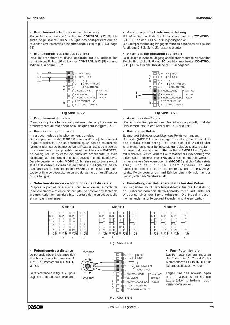
- PMS2000 System -
Ref. 11/595 PMW500-V
- PMS2000 System -
Ref. 11/595 PMW500-V
• Branchement des entrées (option)Pour le branchement d'une seconde entrée, utiliser lesterminaisons 8, 9 et 10 du bornier ‘CONTROL I/O’ [8] commeindiqué à la figure 3.5.2.
• Potentiomètre à distanceLe potentiomètre à distance doitêtre branché aux terminaisons 6,7 et 8 du bornier ‘CONTROL I/O’ [8].
Faire référence à la fig. 3.5.5 pouraugmenter ou abaisser le volume.
Fig./Abb. 3.5.5
• Branchement à la ligne des haut-parleursRaccorder la terminaison 1 du bornier ‘CONTROL I/O’ [8] à lasortie de puissance 100 V. La ligne des haut-parleurs doit enrevanche être raccordée à la terminaison 2 (voir fig. 3.3.3, page21).
Fig./Abb. 3.5.2
C
O
N
T
R
O
L
I
/
OTO SPEAKER LINE
TO POWER OUTPUT
RELAY
NORMAL OPEN
COMMON
NORMAL CLOSED
V max 100V
I max 3A
IN +INPUT
LINE
IN -10
9
1
2
8
7
6
5
4
3
REMOTE VOL.
min. 10K LIN.
IN –
IN +C
O
N
T
R
O
L
I
/
OTO SPEAKER LINE
TO POWER OUTPUT
RELAY
NORMAL OPEN
COMMON
NORMAL CLOSED
V max 100V
I max 3A
IN +INPUT
LINE
IN -10
9
1
2
8
7
6
5
4
3
REMOTE VOL.
min. 10K LIN.
• Branchement du relaisComme indiqué sur le panneau postérieur de l'amplificateur, lesbranchements du relais sont ceux indiqués sur la figure 3.5.3.
• Fonctionnement du relaisIl y a trois modes de fonctionnement du relais.Dans le premier mode (MODE 0 - valeur d'usine), le relais esttoujours excité et il ne se désexcite qu'en cas de coupure del'alimentation ou de panne de l'amplificateur. Dans ce mode defonctionnement il est possible, en utilisant la carte PM2095,de configurer un système de plusieurs amplificateurs avecl'activation automatique d'une ou de plusieurs unités de réserve.Dans le deuxième mode (MODE 1), le relais est toujours excitéet il ne se désexcite qu'en cas de panne sur la ligne des hauts-parleurs. Dans le troisième mode (MODE 2), le relais est toujoursexcité et il ne se désexcite qu'en cas de panne de l'amplificateurou sur la ligne.
• Sélection du mode de fonctionnement du relaisCi-après la procédure à suivre pour sélectionner le mode defonctionnement à l'aide de l'interrupteur à positions multiples dela carte. Actionner les micro-interrupteurs de façon séquentielleet non pas simultanée.
Fig./Abb. 3.5.3
d
51
23
4
ON
67
8
a
51
23
4
ON
67
8
b
51
23
4
ON
67
8
c
51
23
4
ON
67
8
MODE 0
da
51
23
4
ON
67
8
b
51
23
4
ON
67
8
c
51
23
4
ON
67
8
51
23
4
ON
67
8
MODE 1
da
51
23
4
ON
67
8
b
51
23
4
ON
67
8
c
51
23
4
ON
67
8
51
23
4
ON
67
8
MODE 2
C
O
N
T
R
O
L
I
/
OTO SPEAKER LINE
TO POWER OUTPUT
RELAY
NORMAL OPEN
COMMON
NORMAL CLOSED
V max 100V
I max 3A
IN +INPUT
LINE
IN -10
9
1
2
8
7
6
5
4
3
REMOTE VOL.
min. 10K LIN.
Volume
–
Volume
+
Fig./Abb. 3.5.4
• Anschluss der Eingänge (optional)Falls Sie einen zweiten Eingang anschließen möchten, verwendenSie die Endstücke 8, 9 und 10 des Klemmenbretts ‘CONTROLI/O’ [8], wie in der Abbildung 3.5.2 angegeben.
• Anschluss an die LautsprecherleitungSchließen Sie das Endstück 1 des Klemmenbretts ‘CONTROLI/O’ [8] an den 100 V Leistungsausgang an.Die Lautsprecherleitung hingegen muss an das Endstück 2 (sieheAbbildung 3.3.3, Seite 21) gesetzt werden.
• Anschluss des RelaisWie auf dem Rückpaneel des Verstärkers dargestellt, sind dieRelaisanschlüsse in der Abbildung 3.5.3 erläutert.
• Betrieb des RelaisEs sind drei Betriebsmodalitäten des Relais vorhanden.Die erste (MODE 0 - werkseitige Einstellung) sieht vor, dassdas Relais stets erregt ist und nur bei Ausfal l derStromversorgung oder bei Beschädigung des Verstärkers abfällt.In diesem Modus kann mit Hilfe der Karte PM2095 ein Systemmit mehreren Verstärkern mit automatischer Einschaltung voneinem oder mehreren Reserveverstärkern eingestellt werden.In der zweiten Betriebsmodalität (MODE 1) ist das Relais stetserregt und fä l l t nur bei e inem Schaden an derLautsprecherleitung ab. In der dritten Modalität (MODE 2)ist das Relais stets erregt und fällt bei einem Schaden an derLeitung oder am Verstärker ab.
• Einstellung der Betriebsmodalitäten des RelaisIm Folgenden wird Handlungsabfolge für die Einstellungder unterschiedlichen Betriebsmodalitäten mit Hilfe derWippenschalter der Karte erläutert. Die Hebel müssennacheinander hinuntergedrückt werden (nicht gleichzeitig).
• Fern-PotentiometerDas Fernpotentiometer muss andie Endstücke 6, 7 und 8 desKlemmenbretts ‘CONTROL I/O’[8] angeschlossen werden.
Folgen Sie den Anweisungenin Abb. 3.5.5, wenn Sie dieLautstärke erhöhen odervermindern wollen.
5.3 CalibragesCette opération doit être effectuée uniquement par unpersonnel qualifié muni des appareillages nécessaires àcet effet. Le calibrage est nécessaire uniquement après uneréparation des étages d'amplification, par exemple après lechangement d'un ou de plusieurs transistors terminaux.1- Régler le P101 (avec le dissipateur à la temp. ambiante)
jusqu'à mesurer une tension de 6 mV au niveau desterminaisons de R110.
2- Régler le P151 (avec le dissipateur à la temp. ambiante)jusqu'à mesurer une tension de 6 mV au niveau desterminaisons de R160.
5.3 EichungenDiese Maßnahme darf nur von Fachpersonalvorgenommen werden, das über entsprechende Geräteverfügt. Die Eichung ist nur nach einer Reparatur derbetroffenen Verstärkerstufen erforderlich, z. Beispiel, beiAuswechseln eines oder mehrerer Endtransistoren.1- P101 regulieren (mit Hilfe des Hitzeableiters) bis an den
Enden von R110 eine Spannung von 6 mV gemessen wird.2- P151 regulieren (mit Hilfe des Hitzeableiters) bis an den
Enden von R160 eine Spannung von 6 mV gemessen wird.
6. CARACTÉRISTIQUES TECHNIQUES 6. TECHNISCHE EIGENSCHAFTEN
Puissance nom inale de sortie 500 W Nom inale A usgangleistung
Sorties à tension constante 100, 70, 50, 90 V(20, 9.4, 5, 16 Ω) A usgänge bei G leichspannung
Distorsion à la puissanvce nom inale < 1% Verzerrung bei Nom inalleistung
Fréquence de coupure du filtre (Low Cut) 320 Hz ± 20 Hz Filterabschnittfrequenz (Low Cut)
Vm ax relais 100 V Vm ax Relais
Seuil d 'activation (m od. Low Power) ~ 55 m V A ktivierungsschwelle (Mod. Low Power)
Seuil de lecture 20 kHz (entrée) ~ 30 m V Leseschwelle 20 kHz (Eingang)
C OM M U NIC A T ION SÉ R IE • R S485 • SE R IE LLE K OM M U NIK A T ION
Vitesse 19200 bit/s Geschwindigkeit
Modalité de transm ision 8 bit Ü bertragungsm odalität
Bit de parité no Päritatsb it
Stop b it 1 Stop bit
ENT RÉES XLR • XLR-EINGÄ NGE
Sensib il ité/Im pédance 775 mV 100 kΩ Em pfindlichkeit/Im pedanz
Rapport signal/bruit > 80 dB Verhältn is von S ignal/Störung
Réponse en fréquence 50 ÷ 20000 Hz (0/-3 dB) Frequenzgang
ENT R ÉE BORNIER • EINGA NG KLEMMENBRET T
Sensib il ité/Im pédance 720 mV 100 kΩ Em pfindlichkeit/Im pedanz
Rapport signal/bruit > 80 dB Verhältn is von S ignal/Störung
Réponse en fréquence 50 ÷ 20000 Hz (0/-3 dB) Frequenzgang
CONDIT IONS DE FONC T IONNEMENT • BET RIEBSBEDIGUNGEN
A lim entation de secteur 230 V ± 10% 50 / 60 Hz Netzeinspeisung
Consom m ation de puissance (@ 230Vca) 950 W / 1150 VA Leistungsaufnahm e (@ 230V-WS)
A lim entation externe en courant continu 22 ÷ 28 V Externe G leichsstrom einspeisung
Consom m ation de puissance (@ 22÷28Vcc) 25 A (MA X) Leistungsaufnahm e (@ 22÷28V-GS)
D im ensions 482 x 133 x 420 mm A bm essungen
Po ids 25 kg Gewicht
Tem pérature de m ise en service /Tem pérature de stockage
-10°C ÷ +45°C-40°C ÷ +70°C
Betriebstem peratur /Lagerungstem peratur
Hum id ité relative < 90 % Relative Feuchtigkeit
Sécurité selon norm e CEI EN 60065 Sicherheits gem äß
30 23

- PMS2000 System -
Ref. 11/595 PMW500-V
- PMS2000 System -
Ref. 11/595 PMW500-V
• Connecteur ‘REMOTE CONTROL’Ce connecteur doit être utilisé pour le branchement del'amplificateur à un PC.
3.5.2 Modalités de fonctionnementDeux modalités de fonctionnement de la carte sont disponibles:• Modalité ‘STAND-ALONE’;• Modalité ‘REMOTE CONTROL’ (Contrôle à distance).Les chapitres ci-dessous décrivent les configurations et lesmodifications qu'il est possible d'appliquer à la carte selonchacune des deux modalités de fonctionnement.
A) Modalité ‘STAND-ALONE’Cette modalité nécessite la configuration d'un certain nombrede paramètres par l'intermédiaire du dip-switch ‘MODE SEL.’prévu à cet effet et présent sur la partie postérieure del'amplificateur.NOTE: le levier 1 du dip-switch assure la fonction ‘Envoi’: elledoit être utilisée pour valider les sélections effectuées parl'intermédiaire des autres leviers.
Borne Description1 alimentation externe 24V (option)2 alimentation externe 24V (option)3 masse4 sélection entrées5 RS485 +6 alimentation externe 24V (option)7 masse8 masse9 RS485 –
Une fois cette connexion effectuée, il estpossible de contrôler la carte PM2092-V parl'intermédiaire d'un logiciel dédié.Le tableau ci-dessous indique les bornes duconnecteur.
• Acquisition du systèmeUne fois terminée l'installation de la ligne de haut-parleurs etune fois l'amplificateur raccordé comme indiqué au chapitre‘Connexions’, il est nécessaire que l'amplificateur acquièrel'impédance. Cette impédance constituera la référence pour lesmesures effectuées par la suite. Dans le cas où les mesuresseraient supérieures à ± 20% de la mesure de référence,l'amplificateur signalera l'anomalie détectée à travers l'allumaged'un témoin. Pour l'acquisition de l'impédance de référence,procéder comme suit:1. Allumer l'amplificateur.2. Intervenir sur le dip-switch en plaçant sur la position ON le
levier 8 et ensuite le levier 1 comme indiqué sur la figure3.5.7.
Le voyant vert ‘OK’ devra clignoter deux fois et rester allumésans clignoter au bout de quelques secondes, indiquant ainsique l'acquisition de la ligne s'est effectuée correctement.3. Ramener les leviers 1 et 8 sur la position OFF: le voyant vert
doit alors s'éteindre.
Fig./Abb. 3.5.6
Fig./Abb. 3.5.7
• Anschlussstück ‘REMOTE CONTROL’Dieses Anschlussstück wird für die Verbindung des Verstärkersmit einem Personal Computer verwendet.
Nach Herstellung der Verbindung kann dieEinheit PM2092-V mit Hilfe einer dediziertenSoftware gesteuert werden.In der nachstehenden Tabelle sind diePinstellungen des Anschlussstücks angegeben.
Klem Beschreibung1 Externe Speisung 24V (Optional)2 Externe Speisung 24V (Optional)3 Erdung4 Wahl Eingänge5 RS485 +6 Externe Speisung 24V (Optional)7 Erdung8 Erdung9 RS485 –
3.5.2 BetriebsmodalitätenDie Einheit lässt 2 Betriebsmodalitäten zu:• Modalität ‘STAND-ALONE’;• Modalität ‘REMOTE CONTROL’ (Fernkontrolle).In den folgenden Abschnitten werden alle Einstellungen undÄnderungen beschrieben, die für die Einheit bei beidenBetriebsarten möglich sind.
A) Modalität ‘STAND-ALONE’Bei dieser Modalität müssen bestimmte Parameter mit dementsprechenden Dip-Switch ‘MODE SEL.’ auf der Rückseite desVerstärkers eingestellt werden.
HINWEIS: der Hebel 1 des Dip-Switch hat die Funktion ‘Enter’:er muss folglich betätigt werden, um die mit anderen Hebelngetätigte Wahl zu bestätigen.
• Akquirierung der AnlageNach definitiver Installation der Lautsprecherleitung undAnschluss des Verstärkers gemäß den Anweisungen im Kapitel‘Anschlüsse’, muss der Verstärker die verwendete Impedanzerfassen. Diese Impedanz wird als Bezug für die zukünftigenMessungen verwendet. Falls die Messungen ± 20% desBezugswertes überschreiten, ziegt der Verstärker diesen Zustandmit Hilfe von Leds an.Zur Erfassung der Bezugsimpedanz gehen Sie wie folgt vor:1. Schalten Sie den Verstärker ein.2. Betätigen Sie den Dip-Switch, indem Sie den Hebel 8 in die
Position ON bringen und betätigen Sie anschließend denHebel 1, wie in Abbildung Figure 3.5.7 dargestellt.
Das grüne Led ‘OK’ blinkt zweimal auf und leuchtet nach einigenSekunden stetig, um die korrekte Erfassung der Leitunganzuzeigen.3. Setzen sie den Hebel 1 zurück und den Hebel 8 in die Position
OFF: das Led erlöscht.
4. UTILISATION DE L'APPAREIL4.1 AllumageAvant d'allumer l'appareil, s'assurer que toutes les connexionsnécessaires au fonctionnement de l'installation ont bien étéeffectuées. Placer l'interrupteur de secteur [4] sur la positionON. Le témoin lumineux ‘ON’ [2] doit s'allumer, confirmant ainsila mise sous tension de l'appareil.
4.2 AfficheurLes diodes électroluminescentes (leds) [3] de la façade,exceptée celle relative à l'allumage de l'appareil [2] peuventservir d'indicateurs du niveau de sortie et/ou d'indicateurs del'état de fonctionnement de l'amplificateur (voir le paragraphe‘Afficheur à leds’ à la page 25).
5. NOTES DE SERVICE5.1 Ventilation forcéeLes amplificateurs PMW500-V disposent d'un ventilateur pourassurer le refroidissement forcé des étages finaux de puissanceet des parties internes de l'appareil. Ce ventilateur asservi parun circuit d'alimentation et de contrôle propre, se metautomatiquement en marche lorsque le dissipateur de chaleuratteint un certain seuil de température et s'arrête lorsque latempérature redescend à des valeurs normaux. En conditionsd'utilisation standard, avec des amplificateurs de ce type devantassurer la diffusion de musique d'ambiance interrompue par desannonces vocales à pleine puissance, et en conditions climatiquesnormales, la ventilation forcée n'est pas nécessaire, aussi n'est-elle pas activée; ceci permet de limiter considérablement l'usuredes pièces mécaniques, de limiter l'accumulation de poussière àl'intérieur de l'appareil provoquée par le fonctionnement desventilateurs et, un autre avantage non négligeable, de réduire lebruit produit par un grand nombre de ventilateurs dans le casd'installations composées d'une ou de plusieurs armoirescontenant un grand nombre de boosters. Le ventilateur aspirede l'air frais à travers les fentes postérieures de l'appareil [9] etexpulse l'air chaud à travers les fentes antérieures [1], aussiest-il indispensable que les fentes ne soient pas bouchées.
5.2 Conditions de surcharge et protectionsEn plus de la protection standard assurée par des fusibles, lesamplificateurs PMW500-V disposent d'une protectionélectronique et d'une protection thermique qui les mettent àl'abri de tout risque. Appliquer une valeur d'impédance inférieureà la valeur nominale a pour effet de demander à l'appareil unepuissance supérieure à celle qu'il est en mesure de fournir encontinu. Ceci peut avoir pour effet d'endommager les étagesfinaux de puissance et le transformateur de sortie.Pour prévenir ce risque, les amplificateurs du système modulairesont dotés d'un circuit de protection à recouvrement automatiquecontre les surcharges.Le circuit de protection intervient instantanément surl'amplificateur dans les cas suivants:- court-circuit sur une des sorties haut-parleurs.- impédance de charge inférieure à 50% de la valeur nominale.- puissance demandée par le système des diffuseurs, raccordés
sur les lignes à tension constante, supérieure à celle quel'amplificateur est en mesure de fournir.
La condition de surcharge est signalée par le clignotement duvoyant lumineux ‘OVD’ [3] présent sur le panneau frontal del'appareil. L'appareil reprend son fonctionnement normal dès quela cause de la surcharge est éliminée.La protection thermique, à recouvrement automatiqueégalement, intervient dans le cas où la température de l'appareildeviendrait excessive, par exemple lorsque la températureambiante est trop élevée ou lorsque l'aération du rack estinsuffisante.Après l'intervention de la protection thermique, l'amplificateurcesse de fonctionner, tous les voyants s'éteignent et seul leventilateur continue de fonctionner.
4. GEBRAUCH DES GERÄTS4.1 EinschaltenVor Inbetriebnahme des Geräts sicherstellen, daß al leAnschlüsse für die Fertigstellung der Anlage hergestellt wurden.Den Netzschalter [4] in die Position ON setzen. Das Led ‘ON’[2] bestätigt das Einschalten des Geräts.
4.2 DisplayDie LED [3] des Frontpaneels, mit Ausnahme der LED für dieEinschaltung des Geräts [2] können als Anzeigen für dieAusgangsstufe und oder als Anzeigen des Betriebszustands desVerstärkers funktionieren (s. Abschnitt ‘LED-Display’,Seite 25).
5. HINWEISE FÜR DEN BETRIEB5.1 Zusätzliche VentilationDie Verstärker PMW500-V besitzen ein Kühlrad für die Kühlungder Leistungsendstufen und des Geräteinnern. Dieses Kühlradist mit einem eigenen Versorgungs- und Kontrollschaltkreisausgerüstet und tritt automatisch in Funktion, wenn derHitzeableiter eine bestimmte Temperatur erreicht; er schaltetsich ab, wenn die Temperatur auf ihre normalen Wertezurückgekehrt ist. Praktisch ist bei der typischen Verwendungvon Verstärkern dieser Größe wie die Sendung vonHintergrundmusik und dazwischengeschalteten Durchsagen beihöchster Verstärkung und normalen klimatischen Bedingungenkeine zusätzliche Ventilation erforderlich, sodaß diese Funktionauch nicht aktviert wird; dadurch wird ein wesentlich geringererVerschleiß der in Bewegung befindlichen Komponenten und dieReduzierung von Staubansammlung durch das Lüftungsradverursacht und nicht zuletzt auch eine Verminderung derGeräuschbelastung durch die hohe Anzahl der rotierendenLüftungsräder in Anlagen mit einem oder mehreren Schränken,die zahlreiche Booster enthalten. Das Lüftungsrad zieht Frischluftdurch die rückseitigen Schlitze des Geräts [9] ein und gibt dieerwärmte Luft durch die vorderen Luftschlitze wieder [1]; ausdiesem Grund dürfen die Luftschlitze auf keinen Fall verschlossenwerden.
5.2 Überlastung und ÜberlastungsschutzDie Geräte PMW500-V verfügen, zusätzl ich zu demherkömmlichen Schutz mittels Sicherungen, auch über eineelektronische und eine thermische Sicherung, die sie voreventuellen Risiken der Beschädigung schützen. Bei Betrieb miteinem niedrigeren Impedanzwert als dem Nominalwert wirddem Gerät eine höhere Leistung als die dauerhaft lieferbareabverlangt. Dieser Zustand kann zu einer Beschädigung derEndstufen und des Ausgangstransformators führen.Um dieses Risikos auszuschließen, sind die Verstärker desModulsystems mit einem Schutzschaltkreis gegen Überlastungmit automatischer Wiederaufnahme des Betriebs ausgerüstet.Der Schutzschaltkreis tritt automatisch dann in Funktion, wennam Verstärker die folgendes passiert:- Kurzschluß an einem Lautsprecherausgang.- Impedanz 50% geringer als der Nominalwert.- Vom System der Lautsprecher, die an eine Leitung mit
Konstanter Spannung angeschlossen sind,höhere geforderteLeistung als die vom Verstärker lieferbare.
Der Überlastungszustand wird durch das Blinken des Leds‘OVD’ [3] auf dem Frontpaneel des Geräts angezeigt. Das Gerätnimmt seinen normalen Betrieb wieder auf, sobald die Ursachefür die Belastung beseitigt wurde.Der automatische Überhitzungsschutz setzt dann ein, wenn dasGerät eine zu hohe Temperatur erreicht, z.B., wenn eine zu hoheUmgebungstemperatur vorhanden ist oder bei unzureichenderBelüftung des Racks.Während des Einsatzes des Überhitzungsschutzes, setzt derVerstärker aus, alle Leds schalten sich aus und lediglich dasKühlrad bleibt in Betrieb.
24 29

- PMS2000 System -
Ref. 11/595 PMW500-V
- PMS2000 System -
Ref. 11/595 PMW500-V
• Établissement del'intervalle entre deux tests
Pour établir l'intervalle entre deux tests, on doit utiliser les leviers4 à 8.Le levier 2 correspond au mode ‘test time’.Pour programmer par ex. un intervalle de 5 secondes:1. Amener le levier 2 sur la position ON;2. Amener le levier 1 sur la position ON (Envoi): le voyant vert
‘OK’ doit s'allumer.3. Ramener sur la position OFF le levier 1 et ensuite le levier 2;
le voyant doit alors s'éteindre, indiquant que la programmationa été correctement effectuée.
La figure 3.5.8 montre les exemples de programmation desintervalles standard.
0 = 5 sec. (Intervalle minimum/Mindestintervall)
1 = 1 min
29 = 29 min
30 = 1 h (Intervalle maximum/Maximales Intervall)
Pour les autres valeurs, se reporter à la ‘Planche de configuration’pages 47/48. Une fois l'intervalle programmé, l'amplificateureffectuera les tests à intervalles réguliers. Ceci permettra demonitorer le fonctionnement de l'amplificateur et de s'assureren temps réel de la présence ou de l'absence d'éventuellesdéfectuosités ou d'anomalies de la ligne.
• Afficheur à ledsEn l'absence de pannes, les diodes électroluminescentes de lafaçade de l'amplificateur font fonction de VU-METER. Enprésence d'au moins une panne, la fonction VU-METER estabandonnée et les diodes électroluminescentes indiqueront lapanne détectée (voir le tableau à la page 49).
Fig./Abb. 3.5.8
2 = 2 min 31 = NO TEST
• Contrôle du volumeLors du premier allumage, le réglage du volume de sorties'effectue par l'intermédiaire du trimmer présent à côté duvoyant ‘OK’. Il est également possible de contrôler le volumede l'amplificateur par l'intermédiaire d'un potentiomètre àdistance ou par l'intermédiaire d'une connexion de type sérieau moyen d'un PC et d'un logiciel dédié.
• Einstellung des Intervallszwischen einem Test und dem nächsten
Zur Einstellung des gewünschten Testintervalls müssen die Hebel4 bis 8 verwendet werden.Der Hebel 2 bestimmt den Modus ‘test time’.Stellen wir bspw. ein Intervall von 5 Sekunden ein:1. Bringen Sie den Hebel 2 in die Position ON;2. Bringen Sie den Hebel 1 (Enter) in die Position ON: Das
grüne Led ‘OK’ leuchtet nun stetig.3. Setzen Sie den Hebel 1 und anschließend den Hebel 2 in die
Stellung OFF zurück; das Led erlöscht, um anzuzeigen, dassdie Einstellung korrekt erfasst wurde.
In der Abbildung 3.5.8 finden Sie die Einstellung der gängigenIntervalle.
Für andere Werte konsultieren Sie die ‘Konfigurationsübersicht’auf Seite 47/48. Nach Auswahl der gewünschten Intervalls,wiederholt der Verstärker den Test regelmäßig.Hierdurch ist die Überwachung des Betriebs des Verstärkers unddie Ermittlung in Echtzeit von Schäden und Anomalien der Leitungmöglich.
• LED-DisplayWenn keine Defekte vorliegen, haben die LED am Frontpaneeldie Funktion eines VU-Meters. Wenn auch nur ein Defekt vorliegt,setzt die VU-Meter-Funktion aus und die LED zeigen denerhobenen Defekt an (s. Tabelle auf Seite 49).
• LautstärkekontrolleBeim erstmaligen Einschalten, ist die Lautstärkekontrolle demTrimmer überlassen, der sich seitlich des Leds ‘OK’ befindet.Außerdem besteht die Möglichkeit, die Lautstärke desVerstärkers mit einem Fern-Potentiometer zu kontrollieren oderaber mit einem seriellen Anschluss an einen PC mit dedizierterSoftware.
4. Rallumer amplificateur et s'assurer que le voyant vert ‘OK’s'allume.
5. Ramener le levier 1 sur la position OFF: le voyant ‘OK’ doits'éteindre.
6. Ramener tous les autres leviers sur OFF.
3.5.3 CalibrageL'accouplement carte-amplificateur pouvant entraîner desvariations de gain de l'ordre de 5%, il est possible (mais nonindispensable) de corriger de telles variations en procédant aucalibrage de la manière suivante:1. Raccorder à la ligne de sortie une résistance de 100 ohm et
de précision adaptée.2. En intervenant sur le dip-switch amener sur la position ON
les leviers 2 à 8 comme indiqué à la figure 3.5.15.3. Amener le levier 1 sur la position ON pour valider la sélection
et attendre que le voyant vert ‘OK’ s'allume.4. Ramener le levier 1 sur la position OFF.5. Ramener tous les autres leviers sur la position OFF.Grâce à cette procédure, le mesureur d'impédance effectuerades mesures absolues.
Allocation d’adresse • Adressenzuweisung Calibrage • Kalibrieren
Fig./Abb. 3.5.14 Fig./Abb. 3.5.15
4. Schalten Sie den Verstärker wieder ein und überprüfen Sie,dass das grüne Led ‘OK’ leuchtet.
5. Bringen Sie den Hebel 1 in die Position OFF: das Led ‘OK’erlöscht.
6. Bringen Sie alle Hebel in die Position OFF.
3.5.3 KalibrierenDa die Verbindung von Einheit und Verstärker Gewinnänderungenvon ca. 5% mit sich bringt, ist es möglich (aber nicht notwendig)die Änderungen durch die folgenden Kalibrierungsoperationenzu korrigieren:1. Schließen Sie an die Ausgangsleitung einen Widerstand von
100 ohm mit ausreichender Präzision an.2. Bringen Sie die Hebel 2 bis 8 in die Stellung ON, indem Sie
die Dip-Switch betäitigen, wie in Abbildung Figure 3.5.15dargestellt.
3. Bringen Sie den Hebel 1 in die Position ON, um die Wahlzu bestätigen, und warten Sie, bis das grüne Led ‘OK’beginnt zu leuchten.
4. Bringen Sie den Hebel 1 in die Stellung OFF.5. Bringen Sie alle anderen Hebel in die Stellung OFF.Der Impedanzmesser liefert dann absolute Messungen.
28 25

- PMS2000 System -
Ref. 11/595 PMW500-V
- PMS2000 System -
Ref. 11/595 PMW500-V
Pour sélectionner la source de réglage de volume, intervenir surles leviers du dip-switch comme indiqué à la figure 3.5.9.
Potentiomètre à distance • Fern-potentiometer • Trimmer •
• RS485 •
Fig./Abb. 3.5.9
• Sélection des entréesIl existe deux modes de fonctionnement des entrées:1) entrées commutées.2) entrées mélangées.La valeur d'usine prévoit le mélange des deux entrées(Mode 2); lorsqu'elles sont toutes deux présentes, la prioritésera accordée au signal en provenance des connecteursIN/OUT [10]. Ceci permet, dans le cas des installationsd'évacuation, de garantir le test de l 'amplificateur etl'adressage prioritaire de messages d'alerte et/ou d'évacuation.Pour configurer le mode de commutation, débrancher toutd'abord l'appareil de toutes les sources d'alimentation puisintervenir sur la carte comme suit:1. enlever le carter de protection de l'amplificateur.2. enlever le jumper présent sur le connecteur CN7 (MIX) et
l'installer sur le connecteur CN6 (NO MIX).3. remettre le carter de protection en place.
1) Entrées commutéesLa source permettant à l'amplificateur de prélever le signal peutêtre établie par l'intermédiaire des dip-switch. L'utilisateur peutdécider, selon ses besoins spécifiques, d'utiliser les prises XLRou bien le bornier CONTROL I/O. Lors du premier allumage,la carte sélectionne automatiquement le signal prélevé surl'entrée XLR (configuration usine).La fig. 3.5.10 montre les deux configurations. La configurationeffectuée par l'intermédiaire des dip-switch est enregistrée dansla mémoire non-volatile et est automatiquement réactivée àchaque allumage.
Prises • XLR • Buchsen Bornier • CONTROL I/O • Klemmenbrett
Fig./Abb. 3.5.10
Zur Wahl der zu kontrollierenden Quelle betätigen Sie die Hebeldes Dip-Switch, wie in Abbildung 3.5.9 angegeben.
1) Eingänge im UmschaltbetriebDie Tonquelle, von der der Verstärker die Signale erhält, kannMit Hilfe der Dip-Switch eingestellt werden. Der Bediener kannje nach Erfordernis wählen ob er die XLR-Buchsen oder dasKlemmenbrett CONTROL I/O verwenden will. Beim erstmaligeneinschalten, wählt die Einheit automatisch den XLR-Eingang(werkseitige Einstellung).In der Abb. 3.5.10 sind beide Einstellungen angegeben.Die mit Hilfe der Dip-Switch getätigte Einstellung wird im nicht-flüchtigen Speicher erfasst und bei jedem erneuten Einschaltenangezeigt.
• Auswahl der EingängeDer Betrieb der Eingänge kann in zwei Modi erfolgen:1) Eingänge im Umschaltbetrieb.2) Eingänge im Mischbetrieb.Die werkseitige Einstellung sieht die Mischung der beidenEingänge vor (Mod. 2); falls beide vorhanden sein sollten, hatdas Signal Vorrang, das von den Anschlussstücken IN/OUT[10] kommt. Dies gewährleistet bei Evakuationsanlagen dieDurchführung von Tests des Verstärkers und das vorrangigeSenden von Alarm- und/oder Evakuationsmeldungen.Zur Einstellung des Umschaltmodus muss nach Trennen desGeräts von allen Stromspeisungen an der Karte wie folgtvorgegangen werden:1. Die Abdeckung des Verstärkers entfernen.2. Den Jumper vom Anschlussstück CN7 (MIX) entfernen und
in das Anschlussstück CN6 (NO MIX) einsetzen.3. Die Abdeckung wieder aufsetzen.
La sélection de l'entrée peut également s'effectuer parl'intermédiaire d'un interrupteur à distance. Pour cela, il estnécessaire de raccorder un interrupteur entre les bornes 4 et 8du connecteur ‘REMOTE CONTROL’ comme indiqué à lafig. 3.5.11.
Pour modifier l'entrée par l'intermédiaire de l'interrupteur àdistance, il est nécessaire de sélectionner l'entrée XLR parl'intermédiaire des dip-switch.
• Modalité économie d'énergieEn activant cette fonction, l'amplificateur reste en stand-by pourconsommer une quantité minimum d'énergie, le voyant ‘ON’en ce cas clignote.Le fonctionnement normal est rétabli lorsquela présence d'un signal est relevée par une des deux entrées.
• Filtre ‘LOW CUT’Afin d'améliorer l'audibilité, il est possible d'activer un filtre pourles tonalités graves; pour cela l'utilisateur doit également utiliserles dip-switch afin d'activer la fonction.
Ouvert = XLRFermé = Bornier
Geôffnet = XLRGeschlossen = Klemmenbrett
Fig./Abb. 3.5.11
Filtre • ON • Filter Filtre • OFF • Filter
Fig./Abb. 3.5.12
Low Power • ON Low Power • OFF
Fig./Abb. 3.5.13
B) Modalité ‘REMOTE CONTROL’ (Contrôle à distance)Pour le fonctionnement par contrôle à distance, se reporter àla documentation des logiciels correspondants. Au premierallumage, la configuration usine de la carte prévoit que l'adressesoit égale 1.• Allocation d'adressePour modifier l'adresse procéder comme suit:1. Éteindre l'amplificateur.2. A l'aide d'un crayon, placer le levier 2 sur la position ON et le
levier 1 comme indiqué sur la figure 3.5.14a.3. Une fois ces opérations effectuées, utiliser les leviers 3
à 8 pour sélectionner l'adresse voulu (de 0 à 63), enfaisant référence à la planche de configuration de lespages 47/48.
Die Wahl des Eingangs kann auch über einen Fernschaltererfolgen: Zu diesem Zweck muss ein Schalter der Pinne 4 bis 8 andas Verbindungsstück ‘REMOTE CONTROL’ angeschlossenwerden, wie in Abb. 3.5.11 dargestellt.
Zur Änderung des Eingangs mit Hilfe des Fernschalters, mussder Eingang XLR mit Hilfe der Dip-Switch ausgewählt werden.
• ‘LOW CUT’ FilterZur Verbesserung der Verständlich der Sprache kann einTieftonfilter eingesetzt werden; der Anwender muss auch hierdie Dip-Switch betätigen, um diese Funktion zu aktivieren.
• Modalität zur EnergieeinsparungBei Aktivierung dieser Funktion bleibt der Verstärker in derStand-By Schaltung und verbraucht auf diese Weise eineminimale Menge an Energie: das Led ‘ON’ blinkt. Der normaleBetrieb wird dann aufgenommen, wenn ein Signal von einemder beiden Eingänge empfangen wird.
B) Modalität ‘REMOTE CONTROL’ (Fernkontrolle)Für die Kontrolle mit Hilfe der Fernsteuerung wird auf dieDokumentation der entsprechenden Software verwiesen. Beierstmaligem Einschalten ist die werkseitige Adressenzuweisung1 vorgesehen.• AdressenzuweisungZur Änderung der Adresse gehen Sie wie folgt vor:1. Schalten Sie den Verstärker aus.2. Stellen Sie den Hebel 2 und den Hebel 1 mit Hilfe eines Bleistifts
in die Position ON, wie in der Abbildung 3.5.14a dargestellt.3. Nach dieser Operation betätigen Sie die Hebel 3 bis 8, um
die gewünschte Adresse (von 0 bis 63) einzustellen undgehen Sie hierbei entsprechend der Konfigurationsübersichtauf Seite 47/48.
26 27

- PMS2000 System -
Ref. 11/595 PMW500-V
- PMS2000 System -
Ref. 11/595 PMW500-V
Pour sélectionner la source de réglage de volume, intervenir surles leviers du dip-switch comme indiqué à la figure 3.5.9.
Potentiomètre à distance • Fern-potentiometer • Trimmer •
• RS485 •
Fig./Abb. 3.5.9
• Sélection des entréesIl existe deux modes de fonctionnement des entrées:1) entrées commutées.2) entrées mélangées.La valeur d'usine prévoit le mélange des deux entrées(Mode 2); lorsqu'elles sont toutes deux présentes, la prioritésera accordée au signal en provenance des connecteursIN/OUT [10]. Ceci permet, dans le cas des installationsd'évacuation, de garantir le test de l 'amplificateur etl'adressage prioritaire de messages d'alerte et/ou d'évacuation.Pour configurer le mode de commutation, débrancher toutd'abord l'appareil de toutes les sources d'alimentation puisintervenir sur la carte comme suit:1. enlever le carter de protection de l'amplificateur.2. enlever le jumper présent sur le connecteur CN7 (MIX) et
l'installer sur le connecteur CN6 (NO MIX).3. remettre le carter de protection en place.
1) Entrées commutéesLa source permettant à l'amplificateur de prélever le signal peutêtre établie par l'intermédiaire des dip-switch. L'utilisateur peutdécider, selon ses besoins spécifiques, d'utiliser les prises XLRou bien le bornier CONTROL I/O. Lors du premier allumage,la carte sélectionne automatiquement le signal prélevé surl'entrée XLR (configuration usine).La fig. 3.5.10 montre les deux configurations. La configurationeffectuée par l'intermédiaire des dip-switch est enregistrée dansla mémoire non-volatile et est automatiquement réactivée àchaque allumage.
Prises • XLR • Buchsen Bornier • CONTROL I/O • Klemmenbrett
Fig./Abb. 3.5.10
Zur Wahl der zu kontrollierenden Quelle betätigen Sie die Hebeldes Dip-Switch, wie in Abbildung 3.5.9 angegeben.
1) Eingänge im UmschaltbetriebDie Tonquelle, von der der Verstärker die Signale erhält, kannMit Hilfe der Dip-Switch eingestellt werden. Der Bediener kannje nach Erfordernis wählen ob er die XLR-Buchsen oder dasKlemmenbrett CONTROL I/O verwenden will. Beim erstmaligeneinschalten, wählt die Einheit automatisch den XLR-Eingang(werkseitige Einstellung).In der Abb. 3.5.10 sind beide Einstellungen angegeben.Die mit Hilfe der Dip-Switch getätigte Einstellung wird im nicht-flüchtigen Speicher erfasst und bei jedem erneuten Einschaltenangezeigt.
• Auswahl der EingängeDer Betrieb der Eingänge kann in zwei Modi erfolgen:1) Eingänge im Umschaltbetrieb.2) Eingänge im Mischbetrieb.Die werkseitige Einstellung sieht die Mischung der beidenEingänge vor (Mod. 2); falls beide vorhanden sein sollten, hatdas Signal Vorrang, das von den Anschlussstücken IN/OUT[10] kommt. Dies gewährleistet bei Evakuationsanlagen dieDurchführung von Tests des Verstärkers und das vorrangigeSenden von Alarm- und/oder Evakuationsmeldungen.Zur Einstellung des Umschaltmodus muss nach Trennen desGeräts von allen Stromspeisungen an der Karte wie folgtvorgegangen werden:1. Die Abdeckung des Verstärkers entfernen.2. Den Jumper vom Anschlussstück CN7 (MIX) entfernen und
in das Anschlussstück CN6 (NO MIX) einsetzen.3. Die Abdeckung wieder aufsetzen.
La sélection de l'entrée peut également s'effectuer parl'intermédiaire d'un interrupteur à distance. Pour cela, il estnécessaire de raccorder un interrupteur entre les bornes 4 et 8du connecteur ‘REMOTE CONTROL’ comme indiqué à lafig. 3.5.11.
Pour modifier l'entrée par l'intermédiaire de l'interrupteur àdistance, il est nécessaire de sélectionner l'entrée XLR parl'intermédiaire des dip-switch.
• Modalité économie d'énergieEn activant cette fonction, l'amplificateur reste en stand-by pourconsommer une quantité minimum d'énergie, le voyant ‘ON’en ce cas clignote.Le fonctionnement normal est rétabli lorsquela présence d'un signal est relevée par une des deux entrées.
• Filtre ‘LOW CUT’Afin d'améliorer l'audibilité, il est possible d'activer un filtre pourles tonalités graves; pour cela l'utilisateur doit également utiliserles dip-switch afin d'activer la fonction.
Ouvert = XLRFermé = Bornier
Geôffnet = XLRGeschlossen = Klemmenbrett
Fig./Abb. 3.5.11
Filtre • ON • Filter Filtre • OFF • Filter
Fig./Abb. 3.5.12
Low Power • ON Low Power • OFF
Fig./Abb. 3.5.13
B) Modalité ‘REMOTE CONTROL’ (Contrôle à distance)Pour le fonctionnement par contrôle à distance, se reporter àla documentation des logiciels correspondants. Au premierallumage, la configuration usine de la carte prévoit que l'adressesoit égale 1.• Allocation d'adressePour modifier l'adresse procéder comme suit:1. Éteindre l'amplificateur.2. A l'aide d'un crayon, placer le levier 2 sur la position ON et le
levier 1 comme indiqué sur la figure 3.5.14a.3. Une fois ces opérations effectuées, utiliser les leviers 3
à 8 pour sélectionner l'adresse voulu (de 0 à 63), enfaisant référence à la planche de configuration de lespages 47/48.
Die Wahl des Eingangs kann auch über einen Fernschaltererfolgen: Zu diesem Zweck muss ein Schalter der Pinne 4 bis 8 andas Verbindungsstück ‘REMOTE CONTROL’ angeschlossenwerden, wie in Abb. 3.5.11 dargestellt.
Zur Änderung des Eingangs mit Hilfe des Fernschalters, mussder Eingang XLR mit Hilfe der Dip-Switch ausgewählt werden.
• ‘LOW CUT’ FilterZur Verbesserung der Verständlich der Sprache kann einTieftonfilter eingesetzt werden; der Anwender muss auch hierdie Dip-Switch betätigen, um diese Funktion zu aktivieren.
• Modalität zur EnergieeinsparungBei Aktivierung dieser Funktion bleibt der Verstärker in derStand-By Schaltung und verbraucht auf diese Weise eineminimale Menge an Energie: das Led ‘ON’ blinkt. Der normaleBetrieb wird dann aufgenommen, wenn ein Signal von einemder beiden Eingänge empfangen wird.
B) Modalität ‘REMOTE CONTROL’ (Fernkontrolle)Für die Kontrolle mit Hilfe der Fernsteuerung wird auf dieDokumentation der entsprechenden Software verwiesen. Beierstmaligem Einschalten ist die werkseitige Adressenzuweisung1 vorgesehen.• AdressenzuweisungZur Änderung der Adresse gehen Sie wie folgt vor:1. Schalten Sie den Verstärker aus.2. Stellen Sie den Hebel 2 und den Hebel 1 mit Hilfe eines Bleistifts
in die Position ON, wie in der Abbildung 3.5.14a dargestellt.3. Nach dieser Operation betätigen Sie die Hebel 3 bis 8, um
die gewünschte Adresse (von 0 bis 63) einzustellen undgehen Sie hierbei entsprechend der Konfigurationsübersichtauf Seite 47/48.
26 27
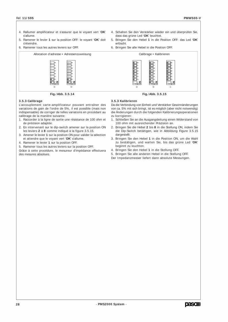
- PMS2000 System -
Ref. 11/595 PMW500-V
- PMS2000 System -
Ref. 11/595 PMW500-V
• Établissement del'intervalle entre deux tests
Pour établir l'intervalle entre deux tests, on doit utiliser les leviers4 à 8.Le levier 2 correspond au mode ‘test time’.Pour programmer par ex. un intervalle de 5 secondes:1. Amener le levier 2 sur la position ON;2. Amener le levier 1 sur la position ON (Envoi): le voyant vert
‘OK’ doit s'allumer.3. Ramener sur la position OFF le levier 1 et ensuite le levier 2;
le voyant doit alors s'éteindre, indiquant que la programmationa été correctement effectuée.
La figure 3.5.8 montre les exemples de programmation desintervalles standard.
0 = 5 sec. (Intervalle minimum/Mindestintervall)
1 = 1 min
29 = 29 min
30 = 1 h (Intervalle maximum/Maximales Intervall)
Pour les autres valeurs, se reporter à la ‘Planche de configuration’pages 47/48. Une fois l'intervalle programmé, l'amplificateureffectuera les tests à intervalles réguliers. Ceci permettra demonitorer le fonctionnement de l'amplificateur et de s'assureren temps réel de la présence ou de l'absence d'éventuellesdéfectuosités ou d'anomalies de la ligne.
• Afficheur à ledsEn l'absence de pannes, les diodes électroluminescentes de lafaçade de l'amplificateur font fonction de VU-METER. Enprésence d'au moins une panne, la fonction VU-METER estabandonnée et les diodes électroluminescentes indiqueront lapanne détectée (voir le tableau à la page 49).
Fig./Abb. 3.5.8
2 = 2 min 31 = NO TEST
• Contrôle du volumeLors du premier allumage, le réglage du volume de sorties'effectue par l'intermédiaire du trimmer présent à côté duvoyant ‘OK’. Il est également possible de contrôler le volumede l'amplificateur par l'intermédiaire d'un potentiomètre àdistance ou par l'intermédiaire d'une connexion de type sérieau moyen d'un PC et d'un logiciel dédié.
• Einstellung des Intervallszwischen einem Test und dem nächsten
Zur Einstellung des gewünschten Testintervalls müssen die Hebel4 bis 8 verwendet werden.Der Hebel 2 bestimmt den Modus ‘test time’.Stellen wir bspw. ein Intervall von 5 Sekunden ein:1. Bringen Sie den Hebel 2 in die Position ON;2. Bringen Sie den Hebel 1 (Enter) in die Position ON: Das
grüne Led ‘OK’ leuchtet nun stetig.3. Setzen Sie den Hebel 1 und anschließend den Hebel 2 in die
Stellung OFF zurück; das Led erlöscht, um anzuzeigen, dassdie Einstellung korrekt erfasst wurde.
In der Abbildung 3.5.8 finden Sie die Einstellung der gängigenIntervalle.
Für andere Werte konsultieren Sie die ‘Konfigurationsübersicht’auf Seite 47/48. Nach Auswahl der gewünschten Intervalls,wiederholt der Verstärker den Test regelmäßig.Hierdurch ist die Überwachung des Betriebs des Verstärkers unddie Ermittlung in Echtzeit von Schäden und Anomalien der Leitungmöglich.
• LED-DisplayWenn keine Defekte vorliegen, haben die LED am Frontpaneeldie Funktion eines VU-Meters. Wenn auch nur ein Defekt vorliegt,setzt die VU-Meter-Funktion aus und die LED zeigen denerhobenen Defekt an (s. Tabelle auf Seite 49).
• LautstärkekontrolleBeim erstmaligen Einschalten, ist die Lautstärkekontrolle demTrimmer überlassen, der sich seitlich des Leds ‘OK’ befindet.Außerdem besteht die Möglichkeit, die Lautstärke desVerstärkers mit einem Fern-Potentiometer zu kontrollieren oderaber mit einem seriellen Anschluss an einen PC mit dedizierterSoftware.
4. Rallumer amplificateur et s'assurer que le voyant vert ‘OK’s'allume.
5. Ramener le levier 1 sur la position OFF: le voyant ‘OK’ doits'éteindre.
6. Ramener tous les autres leviers sur OFF.
3.5.3 CalibrageL'accouplement carte-amplificateur pouvant entraîner desvariations de gain de l'ordre de 5%, il est possible (mais nonindispensable) de corriger de telles variations en procédant aucalibrage de la manière suivante:1. Raccorder à la ligne de sortie une résistance de 100 ohm et
de précision adaptée.2. En intervenant sur le dip-switch amener sur la position ON
les leviers 2 à 8 comme indiqué à la figure 3.5.15.3. Amener le levier 1 sur la position ON pour valider la sélection
et attendre que le voyant vert ‘OK’ s'allume.4. Ramener le levier 1 sur la position OFF.5. Ramener tous les autres leviers sur la position OFF.Grâce à cette procédure, le mesureur d'impédance effectuerades mesures absolues.
Allocation d’adresse • Adressenzuweisung Calibrage • Kalibrieren
Fig./Abb. 3.5.14 Fig./Abb. 3.5.15
4. Schalten Sie den Verstärker wieder ein und überprüfen Sie,dass das grüne Led ‘OK’ leuchtet.
5. Bringen Sie den Hebel 1 in die Position OFF: das Led ‘OK’erlöscht.
6. Bringen Sie alle Hebel in die Position OFF.
3.5.3 KalibrierenDa die Verbindung von Einheit und Verstärker Gewinnänderungenvon ca. 5% mit sich bringt, ist es möglich (aber nicht notwendig)die Änderungen durch die folgenden Kalibrierungsoperationenzu korrigieren:1. Schließen Sie an die Ausgangsleitung einen Widerstand von
100 ohm mit ausreichender Präzision an.2. Bringen Sie die Hebel 2 bis 8 in die Stellung ON, indem Sie
die Dip-Switch betäitigen, wie in Abbildung Figure 3.5.15dargestellt.
3. Bringen Sie den Hebel 1 in die Position ON, um die Wahlzu bestätigen, und warten Sie, bis das grüne Led ‘OK’beginnt zu leuchten.
4. Bringen Sie den Hebel 1 in die Stellung OFF.5. Bringen Sie alle anderen Hebel in die Stellung OFF.Der Impedanzmesser liefert dann absolute Messungen.
28 25

- PMS2000 System -
Ref. 11/595 PMW500-V
- PMS2000 System -
Ref. 11/595 PMW500-V
• Connecteur ‘REMOTE CONTROL’Ce connecteur doit être utilisé pour le branchement del'amplificateur à un PC.
3.5.2 Modalités de fonctionnementDeux modalités de fonctionnement de la carte sont disponibles:• Modalité ‘STAND-ALONE’;• Modalité ‘REMOTE CONTROL’ (Contrôle à distance).Les chapitres ci-dessous décrivent les configurations et lesmodifications qu'il est possible d'appliquer à la carte selonchacune des deux modalités de fonctionnement.
A) Modalité ‘STAND-ALONE’Cette modalité nécessite la configuration d'un certain nombrede paramètres par l'intermédiaire du dip-switch ‘MODE SEL.’prévu à cet effet et présent sur la partie postérieure del'amplificateur.NOTE: le levier 1 du dip-switch assure la fonction ‘Envoi’: elledoit être utilisée pour valider les sélections effectuées parl'intermédiaire des autres leviers.
Borne Description1 alimentation externe 24V (option)2 alimentation externe 24V (option)3 masse4 sélection entrées5 RS485 +6 alimentation externe 24V (option)7 masse8 masse9 RS485 –
Une fois cette connexion effectuée, il estpossible de contrôler la carte PM2092-V parl'intermédiaire d'un logiciel dédié.Le tableau ci-dessous indique les bornes duconnecteur.
• Acquisition du systèmeUne fois terminée l'installation de la ligne de haut-parleurs etune fois l'amplificateur raccordé comme indiqué au chapitre‘Connexions’, il est nécessaire que l'amplificateur acquièrel'impédance. Cette impédance constituera la référence pour lesmesures effectuées par la suite. Dans le cas où les mesuresseraient supérieures à ± 20% de la mesure de référence,l'amplificateur signalera l'anomalie détectée à travers l'allumaged'un témoin. Pour l'acquisition de l'impédance de référence,procéder comme suit:1. Allumer l'amplificateur.2. Intervenir sur le dip-switch en plaçant sur la position ON le
levier 8 et ensuite le levier 1 comme indiqué sur la figure3.5.7.
Le voyant vert ‘OK’ devra clignoter deux fois et rester allumésans clignoter au bout de quelques secondes, indiquant ainsique l'acquisition de la ligne s'est effectuée correctement.3. Ramener les leviers 1 et 8 sur la position OFF: le voyant vert
doit alors s'éteindre.
Fig./Abb. 3.5.6
Fig./Abb. 3.5.7
• Anschlussstück ‘REMOTE CONTROL’Dieses Anschlussstück wird für die Verbindung des Verstärkersmit einem Personal Computer verwendet.
Nach Herstellung der Verbindung kann dieEinheit PM2092-V mit Hilfe einer dediziertenSoftware gesteuert werden.In der nachstehenden Tabelle sind diePinstellungen des Anschlussstücks angegeben.
Klem Beschreibung1 Externe Speisung 24V (Optional)2 Externe Speisung 24V (Optional)3 Erdung4 Wahl Eingänge5 RS485 +6 Externe Speisung 24V (Optional)7 Erdung8 Erdung9 RS485 –
3.5.2 BetriebsmodalitätenDie Einheit lässt 2 Betriebsmodalitäten zu:• Modalität ‘STAND-ALONE’;• Modalität ‘REMOTE CONTROL’ (Fernkontrolle).In den folgenden Abschnitten werden alle Einstellungen undÄnderungen beschrieben, die für die Einheit bei beidenBetriebsarten möglich sind.
A) Modalität ‘STAND-ALONE’Bei dieser Modalität müssen bestimmte Parameter mit dementsprechenden Dip-Switch ‘MODE SEL.’ auf der Rückseite desVerstärkers eingestellt werden.
HINWEIS: der Hebel 1 des Dip-Switch hat die Funktion ‘Enter’:er muss folglich betätigt werden, um die mit anderen Hebelngetätigte Wahl zu bestätigen.
• Akquirierung der AnlageNach definitiver Installation der Lautsprecherleitung undAnschluss des Verstärkers gemäß den Anweisungen im Kapitel‘Anschlüsse’, muss der Verstärker die verwendete Impedanzerfassen. Diese Impedanz wird als Bezug für die zukünftigenMessungen verwendet. Falls die Messungen ± 20% desBezugswertes überschreiten, ziegt der Verstärker diesen Zustandmit Hilfe von Leds an.Zur Erfassung der Bezugsimpedanz gehen Sie wie folgt vor:1. Schalten Sie den Verstärker ein.2. Betätigen Sie den Dip-Switch, indem Sie den Hebel 8 in die
Position ON bringen und betätigen Sie anschließend denHebel 1, wie in Abbildung Figure 3.5.7 dargestellt.
Das grüne Led ‘OK’ blinkt zweimal auf und leuchtet nach einigenSekunden stetig, um die korrekte Erfassung der Leitunganzuzeigen.3. Setzen sie den Hebel 1 zurück und den Hebel 8 in die Position
OFF: das Led erlöscht.
4. UTILISATION DE L'APPAREIL4.1 AllumageAvant d'allumer l'appareil, s'assurer que toutes les connexionsnécessaires au fonctionnement de l'installation ont bien étéeffectuées. Placer l'interrupteur de secteur [4] sur la positionON. Le témoin lumineux ‘ON’ [2] doit s'allumer, confirmant ainsila mise sous tension de l'appareil.
4.2 AfficheurLes diodes électroluminescentes (leds) [3] de la façade,exceptée celle relative à l'allumage de l'appareil [2] peuventservir d'indicateurs du niveau de sortie et/ou d'indicateurs del'état de fonctionnement de l'amplificateur (voir le paragraphe‘Afficheur à leds’ à la page 25).
5. NOTES DE SERVICE5.1 Ventilation forcéeLes amplificateurs PMW500-V disposent d'un ventilateur pourassurer le refroidissement forcé des étages finaux de puissanceet des parties internes de l'appareil. Ce ventilateur asservi parun circuit d'alimentation et de contrôle propre, se metautomatiquement en marche lorsque le dissipateur de chaleuratteint un certain seuil de température et s'arrête lorsque latempérature redescend à des valeurs normaux. En conditionsd'utilisation standard, avec des amplificateurs de ce type devantassurer la diffusion de musique d'ambiance interrompue par desannonces vocales à pleine puissance, et en conditions climatiquesnormales, la ventilation forcée n'est pas nécessaire, aussi n'est-elle pas activée; ceci permet de limiter considérablement l'usuredes pièces mécaniques, de limiter l'accumulation de poussière àl'intérieur de l'appareil provoquée par le fonctionnement desventilateurs et, un autre avantage non négligeable, de réduire lebruit produit par un grand nombre de ventilateurs dans le casd'installations composées d'une ou de plusieurs armoirescontenant un grand nombre de boosters. Le ventilateur aspirede l'air frais à travers les fentes postérieures de l'appareil [9] etexpulse l'air chaud à travers les fentes antérieures [1], aussiest-il indispensable que les fentes ne soient pas bouchées.
5.2 Conditions de surcharge et protectionsEn plus de la protection standard assurée par des fusibles, lesamplificateurs PMW500-V disposent d'une protectionélectronique et d'une protection thermique qui les mettent àl'abri de tout risque. Appliquer une valeur d'impédance inférieureà la valeur nominale a pour effet de demander à l'appareil unepuissance supérieure à celle qu'il est en mesure de fournir encontinu. Ceci peut avoir pour effet d'endommager les étagesfinaux de puissance et le transformateur de sortie.Pour prévenir ce risque, les amplificateurs du système modulairesont dotés d'un circuit de protection à recouvrement automatiquecontre les surcharges.Le circuit de protection intervient instantanément surl'amplificateur dans les cas suivants:- court-circuit sur une des sorties haut-parleurs.- impédance de charge inférieure à 50% de la valeur nominale.- puissance demandée par le système des diffuseurs, raccordés
sur les lignes à tension constante, supérieure à celle quel'amplificateur est en mesure de fournir.
La condition de surcharge est signalée par le clignotement duvoyant lumineux ‘OVD’ [3] présent sur le panneau frontal del'appareil. L'appareil reprend son fonctionnement normal dès quela cause de la surcharge est éliminée.La protection thermique, à recouvrement automatiqueégalement, intervient dans le cas où la température de l'appareildeviendrait excessive, par exemple lorsque la températureambiante est trop élevée ou lorsque l'aération du rack estinsuffisante.Après l'intervention de la protection thermique, l'amplificateurcesse de fonctionner, tous les voyants s'éteignent et seul leventilateur continue de fonctionner.
4. GEBRAUCH DES GERÄTS4.1 EinschaltenVor Inbetriebnahme des Geräts sicherstellen, daß al leAnschlüsse für die Fertigstellung der Anlage hergestellt wurden.Den Netzschalter [4] in die Position ON setzen. Das Led ‘ON’[2] bestätigt das Einschalten des Geräts.
4.2 DisplayDie LED [3] des Frontpaneels, mit Ausnahme der LED für dieEinschaltung des Geräts [2] können als Anzeigen für dieAusgangsstufe und oder als Anzeigen des Betriebszustands desVerstärkers funktionieren (s. Abschnitt ‘LED-Display’,Seite 25).
5. HINWEISE FÜR DEN BETRIEB5.1 Zusätzliche VentilationDie Verstärker PMW500-V besitzen ein Kühlrad für die Kühlungder Leistungsendstufen und des Geräteinnern. Dieses Kühlradist mit einem eigenen Versorgungs- und Kontrollschaltkreisausgerüstet und tritt automatisch in Funktion, wenn derHitzeableiter eine bestimmte Temperatur erreicht; er schaltetsich ab, wenn die Temperatur auf ihre normalen Wertezurückgekehrt ist. Praktisch ist bei der typischen Verwendungvon Verstärkern dieser Größe wie die Sendung vonHintergrundmusik und dazwischengeschalteten Durchsagen beihöchster Verstärkung und normalen klimatischen Bedingungenkeine zusätzliche Ventilation erforderlich, sodaß diese Funktionauch nicht aktviert wird; dadurch wird ein wesentlich geringererVerschleiß der in Bewegung befindlichen Komponenten und dieReduzierung von Staubansammlung durch das Lüftungsradverursacht und nicht zuletzt auch eine Verminderung derGeräuschbelastung durch die hohe Anzahl der rotierendenLüftungsräder in Anlagen mit einem oder mehreren Schränken,die zahlreiche Booster enthalten. Das Lüftungsrad zieht Frischluftdurch die rückseitigen Schlitze des Geräts [9] ein und gibt dieerwärmte Luft durch die vorderen Luftschlitze wieder [1]; ausdiesem Grund dürfen die Luftschlitze auf keinen Fall verschlossenwerden.
5.2 Überlastung und ÜberlastungsschutzDie Geräte PMW500-V verfügen, zusätzl ich zu demherkömmlichen Schutz mittels Sicherungen, auch über eineelektronische und eine thermische Sicherung, die sie voreventuellen Risiken der Beschädigung schützen. Bei Betrieb miteinem niedrigeren Impedanzwert als dem Nominalwert wirddem Gerät eine höhere Leistung als die dauerhaft lieferbareabverlangt. Dieser Zustand kann zu einer Beschädigung derEndstufen und des Ausgangstransformators führen.Um dieses Risikos auszuschließen, sind die Verstärker desModulsystems mit einem Schutzschaltkreis gegen Überlastungmit automatischer Wiederaufnahme des Betriebs ausgerüstet.Der Schutzschaltkreis tritt automatisch dann in Funktion, wennam Verstärker die folgendes passiert:- Kurzschluß an einem Lautsprecherausgang.- Impedanz 50% geringer als der Nominalwert.- Vom System der Lautsprecher, die an eine Leitung mit
Konstanter Spannung angeschlossen sind,höhere geforderteLeistung als die vom Verstärker lieferbare.
Der Überlastungszustand wird durch das Blinken des Leds‘OVD’ [3] auf dem Frontpaneel des Geräts angezeigt. Das Gerätnimmt seinen normalen Betrieb wieder auf, sobald die Ursachefür die Belastung beseitigt wurde.Der automatische Überhitzungsschutz setzt dann ein, wenn dasGerät eine zu hohe Temperatur erreicht, z.B., wenn eine zu hoheUmgebungstemperatur vorhanden ist oder bei unzureichenderBelüftung des Racks.Während des Einsatzes des Überhitzungsschutzes, setzt derVerstärker aus, alle Leds schalten sich aus und lediglich dasKühlrad bleibt in Betrieb.
24 29

- PMS2000 System -
Ref. 11/595 PMW500-V
- PMS2000 System -
Ref. 11/595 PMW500-V
• Branchement des entrées (option)Pour le branchement d'une seconde entrée, utiliser lesterminaisons 8, 9 et 10 du bornier ‘CONTROL I/O’ [8] commeindiqué à la figure 3.5.2.
• Potentiomètre à distanceLe potentiomètre à distance doitêtre branché aux terminaisons 6,7 et 8 du bornier ‘CONTROL I/O’ [8].
Faire référence à la fig. 3.5.5 pouraugmenter ou abaisser le volume.
Fig./Abb. 3.5.5
• Branchement à la ligne des haut-parleursRaccorder la terminaison 1 du bornier ‘CONTROL I/O’ [8] à lasortie de puissance 100 V. La ligne des haut-parleurs doit enrevanche être raccordée à la terminaison 2 (voir fig. 3.3.3, page21).
Fig./Abb. 3.5.2
C
O
N
T
R
O
L
I
/
OTO SPEAKER LINE
TO POWER OUTPUT
RELAY
NORMAL OPEN
COMMON
NORMAL CLOSED
V max 100V
I max 3A
IN +INPUT
LINE
IN -10
9
1
2
8
7
6
5
4
3
REMOTE VOL.
min. 10K LIN.
IN –
IN +C
O
N
T
R
O
L
I
/
OTO SPEAKER LINE
TO POWER OUTPUT
RELAY
NORMAL OPEN
COMMON
NORMAL CLOSED
V max 100V
I max 3A
IN +INPUT
LINE
IN -10
9
1
2
8
7
6
5
4
3
REMOTE VOL.
min. 10K LIN.
• Branchement du relaisComme indiqué sur le panneau postérieur de l'amplificateur, lesbranchements du relais sont ceux indiqués sur la figure 3.5.3.
• Fonctionnement du relaisIl y a trois modes de fonctionnement du relais.Dans le premier mode (MODE 0 - valeur d'usine), le relais esttoujours excité et il ne se désexcite qu'en cas de coupure del'alimentation ou de panne de l'amplificateur. Dans ce mode defonctionnement il est possible, en utilisant la carte PM2095,de configurer un système de plusieurs amplificateurs avecl'activation automatique d'une ou de plusieurs unités de réserve.Dans le deuxième mode (MODE 1), le relais est toujours excitéet il ne se désexcite qu'en cas de panne sur la ligne des hauts-parleurs. Dans le troisième mode (MODE 2), le relais est toujoursexcité et il ne se désexcite qu'en cas de panne de l'amplificateurou sur la ligne.
• Sélection du mode de fonctionnement du relaisCi-après la procédure à suivre pour sélectionner le mode defonctionnement à l'aide de l'interrupteur à positions multiples dela carte. Actionner les micro-interrupteurs de façon séquentielleet non pas simultanée.
Fig./Abb. 3.5.3
d
51
23
4
ON
67
8
a
51
23
4
ON
67
8
b
51
23
4
ON
67
8
c
51
23
4
ON
67
8
MODE 0
da
51
23
4
ON
67
8
b
51
23
4
ON
67
8
c
51
23
4
ON
67
8
51
23
4
ON
67
8
MODE 1
da
51
23
4
ON
67
8
b
51
23
4
ON
67
8
c
51
23
4
ON
67
8
51
23
4
ON
67
8
MODE 2
C
O
N
T
R
O
L
I
/
OTO SPEAKER LINE
TO POWER OUTPUT
RELAY
NORMAL OPEN
COMMON
NORMAL CLOSED
V max 100V
I max 3A
IN +INPUT
LINE
IN -10
9
1
2
8
7
6
5
4
3
REMOTE VOL.
min. 10K LIN.
Volume
–
Volume
+
Fig./Abb. 3.5.4
• Anschluss der Eingänge (optional)Falls Sie einen zweiten Eingang anschließen möchten, verwendenSie die Endstücke 8, 9 und 10 des Klemmenbretts ‘CONTROLI/O’ [8], wie in der Abbildung 3.5.2 angegeben.
• Anschluss an die LautsprecherleitungSchließen Sie das Endstück 1 des Klemmenbretts ‘CONTROLI/O’ [8] an den 100 V Leistungsausgang an.Die Lautsprecherleitung hingegen muss an das Endstück 2 (sieheAbbildung 3.3.3, Seite 21) gesetzt werden.
• Anschluss des RelaisWie auf dem Rückpaneel des Verstärkers dargestellt, sind dieRelaisanschlüsse in der Abbildung 3.5.3 erläutert.
• Betrieb des RelaisEs sind drei Betriebsmodalitäten des Relais vorhanden.Die erste (MODE 0 - werkseitige Einstellung) sieht vor, dassdas Relais stets erregt ist und nur bei Ausfal l derStromversorgung oder bei Beschädigung des Verstärkers abfällt.In diesem Modus kann mit Hilfe der Karte PM2095 ein Systemmit mehreren Verstärkern mit automatischer Einschaltung voneinem oder mehreren Reserveverstärkern eingestellt werden.In der zweiten Betriebsmodalität (MODE 1) ist das Relais stetserregt und fä l l t nur bei e inem Schaden an derLautsprecherleitung ab. In der dritten Modalität (MODE 2)ist das Relais stets erregt und fällt bei einem Schaden an derLeitung oder am Verstärker ab.
• Einstellung der Betriebsmodalitäten des RelaisIm Folgenden wird Handlungsabfolge für die Einstellungder unterschiedlichen Betriebsmodalitäten mit Hilfe derWippenschalter der Karte erläutert. Die Hebel müssennacheinander hinuntergedrückt werden (nicht gleichzeitig).
• Fern-PotentiometerDas Fernpotentiometer muss andie Endstücke 6, 7 und 8 desKlemmenbretts ‘CONTROL I/O’[8] angeschlossen werden.
Folgen Sie den Anweisungenin Abb. 3.5.5, wenn Sie dieLautstärke erhöhen odervermindern wollen.
5.3 CalibragesCette opération doit être effectuée uniquement par unpersonnel qualifié muni des appareillages nécessaires àcet effet. Le calibrage est nécessaire uniquement après uneréparation des étages d'amplification, par exemple après lechangement d'un ou de plusieurs transistors terminaux.1- Régler le P101 (avec le dissipateur à la temp. ambiante)
jusqu'à mesurer une tension de 6 mV au niveau desterminaisons de R110.
2- Régler le P151 (avec le dissipateur à la temp. ambiante)jusqu'à mesurer une tension de 6 mV au niveau desterminaisons de R160.
5.3 EichungenDiese Maßnahme darf nur von Fachpersonalvorgenommen werden, das über entsprechende Geräteverfügt. Die Eichung ist nur nach einer Reparatur derbetroffenen Verstärkerstufen erforderlich, z. Beispiel, beiAuswechseln eines oder mehrerer Endtransistoren.1- P101 regulieren (mit Hilfe des Hitzeableiters) bis an den
Enden von R110 eine Spannung von 6 mV gemessen wird.2- P151 regulieren (mit Hilfe des Hitzeableiters) bis an den
Enden von R160 eine Spannung von 6 mV gemessen wird.
6. CARACTÉRISTIQUES TECHNIQUES 6. TECHNISCHE EIGENSCHAFTEN
Puissance nom inale de sortie 500 W Nom inale A usgangleistung
Sorties à tension constante 100, 70, 50, 90 V(20, 9.4, 5, 16 Ω) A usgänge bei G leichspannung
Distorsion à la puissanvce nom inale < 1% Verzerrung bei Nom inalleistung
Fréquence de coupure du filtre (Low Cut) 320 Hz ± 20 Hz Filterabschnittfrequenz (Low Cut)
Vm ax relais 100 V Vm ax Relais
Seuil d 'activation (m od. Low Power) ~ 55 m V A ktivierungsschwelle (Mod. Low Power)
Seuil de lecture 20 kHz (entrée) ~ 30 m V Leseschwelle 20 kHz (Eingang)
C OM M U NIC A T ION SÉ R IE • R S485 • SE R IE LLE K OM M U NIK A T ION
Vitesse 19200 bit/s Geschwindigkeit
Modalité de transm ision 8 bit Ü bertragungsm odalität
Bit de parité no Päritatsb it
Stop b it 1 Stop bit
ENT RÉES XLR • XLR-EINGÄ NGE
Sensib il ité/Im pédance 775 mV 100 kΩ Em pfindlichkeit/Im pedanz
Rapport signal/bruit > 80 dB Verhältn is von S ignal/Störung
Réponse en fréquence 50 ÷ 20000 Hz (0/-3 dB) Frequenzgang
ENT R ÉE BORNIER • EINGA NG KLEMMENBRET T
Sensib il ité/Im pédance 720 mV 100 kΩ Em pfindlichkeit/Im pedanz
Rapport signal/bruit > 80 dB Verhältn is von S ignal/Störung
Réponse en fréquence 50 ÷ 20000 Hz (0/-3 dB) Frequenzgang
CONDIT IONS DE FONC T IONNEMENT • BET RIEBSBEDIGUNGEN
A lim entation de secteur 230 V ± 10% 50 / 60 Hz Netzeinspeisung
Consom m ation de puissance (@ 230Vca) 950 W / 1150 VA Leistungsaufnahm e (@ 230V-WS)
A lim entation externe en courant continu 22 ÷ 28 V Externe G leichsstrom einspeisung
Consom m ation de puissance (@ 22÷28Vcc) 25 A (MA X) Leistungsaufnahm e (@ 22÷28V-GS)
D im ensions 482 x 133 x 420 mm A bm essungen
Po ids 25 kg Gewicht
Tem pérature de m ise en service /Tem pérature de stockage
-10°C ÷ +45°C-40°C ÷ +70°C
Betriebstem peratur /Lagerungstem peratur
Hum id ité relative < 90 % Relative Feuchtigkeit
Sécurité selon norm e CEI EN 60065 Sicherheits gem äß
30 23

- PMS2000 System -
Ref. 11/595 PMW500-V
- PMS2000 System -
Ref. 11/595 PMW500-V
3.4 Carte translateur de lignePour installer cet accessoire, il est nécessaire d'enlever lecouvercle de l'appareil. Après avoir identifié le connecteur CN204(part. [A], fig. 3.4.1), il fautenlever les pontets de court-circuitqui sont insérés dans celui-ci etinstaller, à leur place, la carteTM92.
Refermer l'unité en remettant lecouvercle à sa place.
Fig./Abb. 3.4.1
Fig./Abb. 3.5.1
3.5.1 BranchementsLe bornier ‘CONTROL I/O’ [8] présentsur le panneau postérieur de l'amplificateurdoit être utilisé pour les branchementsprincipaux de la carte.
3.5 Carte de contrôleLa dotation de série prévoit la présence, à l'intérieur del'amplificateur, de la carte de contrôle PM2092-V spécialementcréée pour assurer l'exécution simple et rapide de tests surl'amplificateur même et de la (ou des) ligne(s) des hauts-parleursen utilisant des cartes PM2094-V. Cette carte est en mesure degérer l'ensemble des fonctions de l'amplificateur, des entréesaux fonctions de diagnostic, et permet en outre d'assurer lesfonctions suivantes:• mesures d'impédance de ligne;• diagnostic de l'amplificateur;• vérification de l'intégrité de la ligne des haut-parleurs.• contrôle de l'isolation de terre (GND FAULT);• contrôle du volume;• sélection de deux entrées;• contrôle du relais de puissance;• activation du filtre ‘LOW CUT’;• fonctionnement modalité économie d'énergie ‘LOW POWER’.La carte peut également être contrôlée par une interface de typesérie. Outre la possibilité d'effectuer l'ensemble des opérationset/ou contrôles programmés localement par l'intermédiaire desdip-switch, elle offre la possibilité de visualiser et de modifierl'ensemble des paramètres, parmi lesquels:• lecture de l'impédance de référence pour le test;• valeur minimum et maximum établissant la validité du test;• lecture de l'état des tests;• test de l'entrée;• mesure de la température des transistors terminaux;• réglage du volume;• commande à distance du relais.
C
O
N
T
R
O
L
I
/
OTO SPEAKER LINE
TO POWER OUTPUT
RELAY
NORMAL OPEN
COMMON
NORMAL CLOSED
V max 100V
I max 3A
IN +INPUT
LINE
IN -10
9
1
2
8
7
6
5
4
3
REMOTE VOL.
min. 10K LIN.
Nombre de diffuseurs =833 Ω20 Ω
= 41
Exemple: utilisation d'un amplificateur PMW500-V avecdiffuseurs dont l'impédance nominale est de 833 ohm(correspondant à une puissance de 12 W sur ligne à 100 V). Letableau 3.3.1 indique que l'impédance nominale de la ligne desortie à 100 V est égale à 20 ohm. Aussi:
Beispiel: man nehme einen Verstärker PMW500-V mitLautsprechern mit einer nominalen Impedanz von 833 ohm(entsprechend einer Leistung von 12 W bei einer 100 V-Leitung).Aus der Tabelle 3.3.1 entnimmt man die nominale Impedanz desAusgangsleitung mit 100 V, entsprechend 20 ohm. Daraus ergibtsich:
Anzahl Lautsprecher =833 Ω20 Ω
= 41
3.4 Karte LeitungsüberträgerFür die Installation dieses Zubehörs muss die Abdeckung desGeräts entfernt werden. Nach Erkennen des Anschlussstücks
CN204 (Detail [A], Abb. 3.4.1)müssen die in ihm installiertenkurzschließenden Überbrückungenentfernt und an ihrer Stelle dieKarte TM92 eingesetzt werden.
Die Abdeckung wieder aufsetzenund die Einheit verschließen
3.5 KontrollkarteIm Innern des Verstärkers ist serienmäßig die KontrollkartePM2092-V eingebaut, die zum Zweck der einfachen undzügigen Durchführung von Tests des Verstärkers und derLautsprecherleitung/en mit Hilfe der Karten PM2094-Ventwickelt wurde.Diese Einheit steuert alle Funktionen des Verstärkers, vonEingängen bis hin zur Diagnostik, und ist in der Lage, diefolgenden Funktionen zu übernehmen:• Messung der Leitungsimpedanz;• Diagnose des Verstärkers;• Überprüfung der Unversehrtheit der Lautsprecherleitung.• Überprüfung der Erdschutzleitung (GND FAULT);• Lautstärkekontrolle;• Auswahl von zwei Eingängen;• Kontrolle des Leistungsrelais;• Möglichkeit des Einsatzes des ‘LOW CUT’-Filters;• Betrieb in der energieeinsparenden Modalität ‘LOW POWER’.Die Einheit kann auch über eine serielle Schnittstelle kontrolliertwerden. Außer der Durchführung von Operationen und/oderPrüfungen, die lokal mit Dip-Switch eingestellt werden, könnenalle nachstehenden Parameter gesichtet und geändert werden:• Lesen der Bezugsimpedanz für die Testfunktion;• Minimale und maximale Ergebnisse, innerhalb der der Test
gültig ist;• Lesen des Testzustands;• Eingangstest;• Messung der Temperatur der Endtransistoren;• Lautstärkeregelung;• Fernsteuerung des Relais.
3.5.1 AnschlüsseDas Klemmenbrett ‘CONTROL I/O ’[8] auf dem Rückpaneel des Verstärkersmuss verwendet werden, um die Haupt-anschlüsse der Einheit herzustellen.
CI202 R2
30
CN
20
4
C218
R2
29
R2
16
R2
36 R2
33
C2
20
R2
08
D2
18
D2
19
R226 C217
X2
07
C219
CC
N2
02
PR201PR202
X208
A
8. LISTE DES PIÈCES DÉTACHÉES
7. ACCESSOIRES
Carte transformateur de ligne ........................................ TM92
7. ZUBEHÖR
Karte Leitungstransformator ......................................... TM92
8. ERSATZTEILLISTE
Panneau frontal sérigraphié 36/2481-S1 Siebbedrucktes Frontpaneel
Ensemble circuit de puissance (gauche) 27/4253 Einheit Leistungsschaltkreis (links)
Ensemble circuit de puissance (droit) 27/4254 Einheit Leistungsschaltkreis (rechts)
Ensemble circuit carte de contrôle 27/4340-V Einheit Karten-Kontrollschaltkreis
Ensemble circuit limiteur de courant 27/4356 Einheit Strombegrenzungsschaltkreis
Ensemble circuit Vu-Meter 27/4370 Einheit Vu-Meter-Schaltkreis
Ensemble circuit commandes et pilotage 27/4575 Einheit Steuer- und Befehlsschaltkreis
Transformateur d'alimentation TF197 Einspeisungstransformator
Transformateur de sortie TU138/16 Ausgangstransformator
Micro programmé 01PMW1.2 Programmiertes Mikrofon
Interrupteur de secteur 19/113 Netzschalter
Poignée 38/341-VNO Griff
Ventilateur de refroidissement VT7 Kühlventilator
Pont redresseur 50 A – 200 V 16/73 Gleichrichterüberbrückung 50 A - 200 V
Condensateur électrolytique 10000µF 63V 649060103 Elektrolytkondensator 10000µF 63V
Condensateur céramique 2,2 nF 400V 709010222 Keramikkondensator 2.2 nF 400V
Transistor TIP35 17/79 Transistor TIP35
Transistor BD911 17/65 Transistor BD911
22 31

- PMS2000 System -
Ref. 11/595 PMW500-V
- PMS2000 System -
Ref. 11/595 PMW500-V
• Berechnung der Anzahl der Lautsprecher(mit Hilfe der Impedanzwerte)
Wenn die verfügbare Angabe die der Lautsprecherimpedanzist, beträgt die maximale Zahl der anschließbaren Lautsprecher:
Fig./Abb. 3.3.3
• Calcul du nombre de diffuseurs(par l'intermédiaire des puissances)
Si l'on suppose que le choix de l'amplificateur (à savoir lapuissance de sortie) et le type de diffuseurs ainsi que lapuissance absorbée correspondante ont été définis, le nombremaximum de diffuseurs qu'il est possible de raccorder sur laligne s'obtient au moyen de la formule suivante:
Exemple: utilisation d'un amplificateur PMW500-V en mesurede distribuer une puissance de 500 W avec plafonnier depuissance nominal de 10 W; pour connaître le nombre dediffuseurs qu'il est possible de raccorder sur la ligne de sortie, oneffectue le calcul suivant:
3.3.1 Systèmes à tension constanteSur ce type d' instal lat ion, les di f fuseurs, dotés detransformateurs d'adaptation d'impédance, sont tous reliés àla ligne en dérivation (voir l'exemple de la fig. 3.3.3).Ceci permet de faciliter la réalisation de l'installation et dans lecas où un haut-parleur, pour une quelconque raison, sedébrancherait de la ligne, le reste de l'installation continue defonctionner normalement. Les tensions constantes en sortie del'amplificateur sont de 50, 70, 90 et 100V. Pour assurer undimensionnement correct de l'installation (choix de la tensionde ligne de l'appareil et choix de la puissance des diffuseurs), ilest possible de recourir à de différentes méthodes (voir ci-aprèsles exemples de calculs).
puissance amplificateurpuissance diffuseur
Nombre de diffuseurs =
• Calcul du nombre de diffuseurs(par l'intermédiaire des impédances)
Si la donnée d'impédance du diffuseur est disponible, le nombremaximum de diffuseurs qu'il est possible de raccorder sur uneligne est le suivant:
• Connexion aux terminaisons de ligne PM2094-VPour le contrôle de l'intégrité de la ligne des hauts-parleurs, ilfaut connecter à la fin de ligne deux cartes PM2094-V commecela est illustré à la figure 3.3.3.N.B.: les cartes doivent avoir la même adresse logique et lesjumpers CN106 et CN107 (voir livret correspondant) doiventêtre insérés.
MAINS RATING CONSUMPT.
500W RMS 950W230V
50/60Hz
FUSE
T 10 A
CONSUMPT. 800W24V
POWER AMPLIFIERPMW500-V
FUSE
MADE IN ITALY
C
O
N
T
R
O
L
I
/
OTO SPEAKER LINE
TO POWER OUTPUT
RELAY
NORMAL OPEN
COMMON
NORMAL CLOSED
V max 100V
I max 3A
IN +INPUT
LINE
IN -10
9
1
2
8
7
6
5
4
3
REMOTE VOL.
min. 10K LIN.
N.B.: dans les installations d'évacuation VES (Voice Evacuation System), lesconnexions des hauts-parleurs doivent être obligatoirement réalisées commecela est indiqué sur la figure.
3.3.1 Systeme mit konstanter SpannungBei dieser Art von Anlagen sind die mit Transformatoren für dieImpedanzanpassung ausgerüsteten Lautsprecher mitAbzweigleitungen angeschlossen (s. Beispiel in Abb. 3.3.3).Diese Besonderheit erleichtert die Installation einer Anlage, inder ein Lautsprecher sich aus bestimmten Gründen von derLeitung trennt, und die dann ihren normalen Betrieb trotzdemfortsetzen kann. Die vom Verstärker austretenden konstantenSpannungen sind 50, 70, 90 und 100V. Zum Zweck einerkorrekten Einstellung der Größe der Anlage (Wahl derLeitungsspannung des Geräts und Wahl der Leistung desLautsprechers) sind nachstehend verschiedene Verfahrendargestellt, die von numerierten Beispielen erläutert werden.
• Anschlüsse an die Leitungsendstücke PM2094-VFür die Kontrolle der Unversehrtheit der Lautsprecherleitungmüssen am Ende dieser Leitung zwei Karten PM2094-V installiertwerden, wie in der Abbildung 3.3.3 gezeigt.N.B.: Die Karten müssen die gleiche logische Adresse haben;außerdem müssen die Jumper CN106 und CN107 eingesetztwerden (s. entsprechendes Handbuch).
• Berechnung der Anzahl der Lautsprecher(mit Hilfe der Leistungen)
Man nehme an, sowohl den Verstärker (d.h. die Ausgangsleistung),als auch die Art des Lautsprechers mit entsprechenderLeistungsaufnahme definiert zu haben. In diesem Fall ist diemaximale Anzahl der an einer Leitung anschließbaren Lautsprechermit Hilfe der folgenden Formel zu berechnen:
Anzahl Lautsprecher =Leistung Verstärker
Leistung Lautsprecher
Beispiel: man verwende einen Verstärker PMW500-V, dereine Leistung von 500 W mit Deckenlautsprechern mit einemNominalwert von 10 W abgeben kann. Um zu berechnen, wieviele Lautsprecher an die Ausgangsleitung angeschlossenwerden können rechnet man:
500 W10 W
= 50
l'impédance nominale de l'amplificateur est indiquée dans le tableau3.3.1 (page 20).
N.B.: In Evakuationsanlagen VES (Voice Evacuation System) müssen dieAnschlüsse der Lautsprecher zwingend wie dargestellt hergestellt werden.
Die nominale Impedanz des Verstärkers ist in der Tabelle 3.3.1angegeben (Seite 20).
Nombre de diffuseurs =impédance nominal diffuseur
impédance amplificateur
500 W10 W
= 50Nombre de diffuseurs = Anzahl Lautsprecher =
Nennimpedanz LautsprecherVerstärkerimpedanz
Anzahl Lautsprecher =
InleidingWij danken u voor uw keuze van een PASO product enherinneren u eraan dat de productie van ons bedrijf volgenseen certificeerd kwaliteitssysteem plaatsvindt. Onze productenworden daarom in iedere productiefase controleerd zodat u zekertevreden zult zijn met uw aankoop. Eventuele fabrieksfoutjeszijn in de periode dat de garantie geldig is, gedekt. Voor eengoed gebruik van dit product en voor een volledige benuttingvan de prestaties hiervan, raden wij u aan onderstaandegebruiksvoorschriften met aandacht door te lezen.
IntroducciónLes agradecemos que hayan elegido un producto PASO ydeseamos recordarles que nuestra empresa trabaja con sistemade calidad certificado. Todos nuestros productos son puescontrolados en cada fase de la producción para garantizarlesuna plena satisfacción en su adquisición. Para cualquier tipo deeventualidad la garantía cubrirá, durante el periodo de validez,eventuales defectos de fabricación. Les aconsejamos que leandetenidamente y se ajusten a las siguientes instrucciones deuso, para utilizar correctamente este producto y aprovechar almáximo sus prestaciones.
INHOUD
1. Algemene beschrijving .................................... 331.1 Frontpaneel ........................................................... 331.2 Achterpaneel ......................................................... 33
2. Algemene aanwijzingen .................................. 342.1 Installatie .............................................................. 342.2 Voeding en aarding ................................................ 342.3 Veiligheidsvoorschriften ......................................... 34
3. Aansluitingen ................................................... 353.1 Algemene criteria ................................................... 353.2 Lijningang/uitgang ................................................. 353.3 Vermogensuitgangen ............................................. 35
• Volumeregeling .................................................... 353.3.1 Systemen met constante spanning ......................... 363.4 Kaart lijntransformator ........................................... 373.5 Besturingskaart ...................................................... 373.5.1 Aansluitingen ......................................................... 37
• Aansluiting op de luidsprekerslijn ......................... 38• Aansluiting ingangen (optie) ................................ 38• Aansluiting relais ................................................. 38• Werking van het relais ......................................... 38• Werkingsmodus van het relais ............................. 38• Potentiometer met afstandsbediening .................. 38• Connector ‘REMOTE CONTROL’ ............................ 39
3.5.2 Werkwijze .............................................................. 39a) ‘STAND-ALONE’ werkwijze ................................. 39
• Afstemming van installatie ............................. 39• Instelling van een
interval tussen twee tests in ........................... 40• Display met led’s ............................................ 40• Instelling geluidsvolume ................................. 40• Selectie van ingangen .................................... 41• ‘LOW CUT’ Filter ............................................. 42• Energiebesparende mode ............................... 42
b) ‘REMOTE CONTROL’ werkwijze .......................... 42• Adrestoekenning ............................................ 42
3.5.3 Afstellen ................................................................ 43
4. Gebruik van het apparaat ............................... 444.1 Inschakeling .......................................................... 444.2 Display .................................................................. 44
5. Opmerkingen ................................................... 445.1 Geforceerde ventilatie ............................................ 445.2 Overbelasting en beveiligingen .............................. 445.3 Afstellingen ............................................................ 45
6. Technische kenmerken .................................... 45
7. Accessoires ....................................................... 46
8. Lijst vervangingsonderdelen .......................... 46
• Configuratietafel ................................................. 47/48
• Storingscondities ...................................................... 49
SUMARIO
1. Descripción general ......................................... 331.1 Panel frontal .......................................................... 331.2 Panel trasero ......................................................... 33
2. Advertencia generales ..................................... 342.1 Instalación ............................................................. 342.2 Alimentación y conexión a tierra ............................ 342.3 Notas de seguridad ................................................ 34
3. Conexiónes ....................................................... 353.1 Criterios generales ................................................. 353.2 Entrada/salida de línea .......................................... 353.3 Salidas de potencia ................................................ 35
• Ajuste del volumen ............................................. 353.3.1 Sistemas con tensión constante ............................. 363.4 Tarjeta transformador de línea ............................... 373.5 Tarjeta de control .................................................. 373.5.1 Conexiónes ............................................................ 37
• Conexión a la línea altavoces .............................. 38• Conexión entradas (opción) ................................ 38• Conexión relé ...................................................... 38• Funcionamiento del relé ...................................... 38• Modalidad de funcionamiento del relé ................. 38• Potenciómetro remoto ......................................... 38• Conectador ‘REMOTE CONTROL’ ......................... 39
3.5.2 Modalidades de funcionamiento ............................. 39a) Modalidad ‘STAND-ALONE’ ................................ 39
• Adquisición de la instalación ........................... 39• Configuración del intervalo
entre un test y el siguiente ............................. 40• Display de LEDs ............................................. 40• Control de volumen ........................................ 40• Selección de las entradas ............................... 41• Filtro ‘LOW CUT’ ............................................. 42• Modalidad de ahorro energético ..................... 42
b) Modalidad ‘REMOTE CONTROL’ ......................... 42• Asignación dirección ....................................... 42
3.5.3 Calibrado ............................................................... 43
4. Uso del aparato ................................................ 444.1 Encendido .............................................................. 444.2 Display .................................................................. 44
5. Notas de servicio ............................................. 445.1 Ventilación forzada ................................................ 445.2 Condiciones de sobrecarga y protecciones ............. 445.3 Ajustes .................................................................. 45
6. Características técnicas .................................. 45
7. Accesorios ........................................................ 46
8. Lista de las piezas de repuesto ....................... 46
• Tabla de configuración ........................................ 47/48
• Condiciones de avería .............................................. 49
32 21

- PMS2000 System -
Ref. 11/595 PMW500-V
- PMS2000 System -
Ref. 11/595 PMW500-V
3. CONNEXIONS3.1 Critères générauxPour assurer le bon fonctionnement de l'appareil, il est importantde respecter un certain nombre de critères durant lesbranchements:- éviter de positionner câbles et micros sur le meuble de
l'appareil;- éviter de placer des lignes de signal le long des lignes
d'alimentation électrique de secteur; respecter une distanced'au moins 30/40 cm;
- respecter une bonne distance entre les lignes d'entrée et leslignes de sortie;
- positionner les micros hors de l'angle de diffusion desdiffuseurs sonores pour éviter les phénomènes de réactionacoustique (effet Larsen).
3.2 Entrée/sortie de ligneLes prises XLR d'entrée/sortie [10] pour les signaux au niveaude la ligne (0 dB, 775 mV) de l'unité de puissance se trouventsur le panneau postérieur de l'appareil; les prises sontdisposées en parallèle pour faciliter les branchements encascade de plusieurs unités de puissance. La fig. 3.2.1 montreles connexions sur ces prises. L'entrée de l'amplificateur estéquilibrée électroniquement; en cas d'exigences spécifiques,ainsi par exemple dans le cas de câbles de branchement degrande longueur et/ou en cas de champs électromagnétiquesproduisant des interférences, i l est possible d' isolergalvaniquement l'entrée de l'amplificateur au moyen de la carteTM92 (option), dotée de transformateur de ligne (voir chapitre3.4).
Fig./Abb. 3.2.1
1: Blindage / Schirm2: Signal (côté chaud) / Signal (warme Seite)3: Signal (côté froid) / Signal (kalte Seite)
3.3 Sorties de puissanceLes sorties de puissance pour les diffuseurs sont présentessur la plaquette de connexions pour des installations dedistribution à puissance constante (50,70, 90 et 100 V) [6].Le tableau 3.3.1 ci-dessous indique les valeurs nominalesd'impédance sur les prises de sortie à tension constante.
SORTIE PMW500-V50 V 5 Ω
70 V 9,4 Ω
90 V 16 Ω
100 V 20 Ω
Tab. 3.3.1
• Réglage du volumeLe réglage du volume de sortie peut s'effectuer en intervenantsur le trimmer ‘LEVEL’ [11] prévu à cet effet et présent sur lapartie postérieure de l'appareil. En tournant le trimmer, à l'aided'un petit tournevis, dans le sens des aiguilles d'une montre,le volume augmente, dans le sens contraire des aiguilles d'unemontre, il diminue.
Fig./Abb. 3.3.2
IN/OUT
2 1
3
IN/OUT.
E
SEL 8
REMOTE CONTROL
LEVEL OK
3. ANSCHLÜSSE3.1 Allgemeine KriterienZum Zweck eines ordnungsgemäßen Betrieb des Geräts müsseneinige wesentl iche Kriter ien bei der Herstel lung derVerbindungen beachtet:- Das Ablegen von Kabeln und Mikrofonen auf dem
Gerätschrank ist zu vermeiden.- Das Verlegen der Signalleitungen parallel zu den Netzleitungen
ist zu vermeiden, einen Mindestabstand von 30/40 cmeinhalten.
- Die Eingangs- und Ausgangsleitungen müssen in einerbestimmten Entfernung zueinander verlegen.
- Die Mikrofone außerhalb des Ausstrahlungswinkels derLautsprecher aufstellen, um den akustischen Rückhall (Larsen)zu vermeiden.
3.2 Leitungseingang-/AusgangAuf dem Rückpaneel des Geräts sind die Buchsen XLR desEingangs/Ausgangs [10] für die Signale der Leitung (0 dB,775 mV) der Leistungseinheit vorhanden; die Buchsen sindparallel geschaltet, um den Kaskadenanschluß mehrererLeistungseinheiten zu erleichtern. Abb. 3.2.1 zeigt dieAnschlüsse an diese Buchsen. Der Eingang des Verstärkers istelektronisch symmetriert; bei besonderen Anforderungen, wiebspw. bei langen Verbindungskabeln und/oder starkenelektromagnetischen Störfeldern kann der Eingang desVerstärkers mit Hilfe der optionalen Zubehörkarte TM92, diemit einem Leitungstransformator ausgerüstet ist, galvanischisoliert werden (s. Abschnitt 3.4).
3.3 LeistungsausgängeThe power outputs for the loudspeakers are available on theterminal strips for constant-voltage distribution systems (50,70,90 und 100 V) [6] zur Verfügung.In der Tabelle 3.3.1 sind die nominalen Impedanzwerte derAusgangsbuchsen mit Gleichspannung angegeben.
AUSGANG PMW500-V50 V 5 Ω
70 V 9,4 Ω
90 V 16 Ω
100 V 20 Ω
Tab. 3.3.1
• VolumenregulierungDie Regulierung des Ausgangsvolumens kann auf einfacheWeise durch die Bedienung des entsprechenden Trimmers‘LEVEL’ [11] auf der Rückseite des Gerätes erfolgen. DurchDrehen eines kleinen Schraubenziehers im Uhrzeigersinn wirddie Lautstärke erhöht; durch Drehen entgegen demUhrzeigersinn wird sie herabgesetzt.
1. ALGEMENE BESCHRIJVINGDe vermogenseenheid PMW500-V kan, in combinatie met hetsysteem PMS2000, voldoen aan de door de norm IEC 60849gestelde eisen met betrekking tot VES (Voice EvacuationSystem) systemen voor het besturen van noodsituatiesen ontruiming. De componenten van het modulair systeemdie worden aangeduid met het achtervoegsel ‘-V’ volgendop de productcode, zijn zodanig vervaardigd dat zij inovereenstemming zijn met de bovengenoemde norm.
1.1 Frontpaneel[1] Luchtspleten.[2] Controlelampje apparaat aan.[3] Display met led’s.[4] Netschakelaar.
PMW500-V
dB
ON
-10
SPK
-3
OVL
-40
GND
-6
AMP.
0
HOT
ON
OFF
POWER
PROFESSIONAL
MODULAR SYSTEM
1 32 4
CAUTION:DISCONNECT POWERSUPPLY CORDBEFORE CHANGINGFUSE.
CAUTION:TO REDUCE THE RISKOF FIRE, REPLACEONLY WITH SAMETYPE FUSE.
MAINS RATING CONSUMPT.
500W RMS 950W
FUSE
V
230V
50/60Hz
FUSE
T 10 A
CONSUMPT. 800W24V
POWER AMPLIFIERPMW500-V
50V00
90V 70V 100V16 5 9,4 20
FUSE
32A
MADE IN ITALY
CAUTION: DO NOT OBSTRUCT OPENING !
IN/OUT IN/OUT
C
O
N
T
R
O
L
I
/
OTO SPEAKER LINE
TO POWER OUTPUT
RELAY
NORMAL OPEN
COMMON
NORMAL CLOSED
V max 100V
I max 3A
IN +INPUT
LINE
IN -10
9
1
2
8
7
6
5
4
3
REMOTE VOL.
min. 10K LIN.
.
MODE
SEL
1
8
REMOTE CONTROL
LEVEL OK
91011121314
5 6 7 8
1.2 Achterpaneel[5] Klemmenbord voor externe gelijkstroomvoeding.[6] Klemmenbord voor luidsprekers.[7] Dip-switch voor functie-instellingen.[8] Klemmenbord voor aansluitingen.[9] Luchtspleten.[10] Ingangs/Uitgangs-bussen.[11] Regelaar uitgangsvolume.[12] Connector voor afstandsbediening.[13] Netstekker met ingebouwde zekering.[14] Zekering voor beveiliging van de gelijkstroomvoeding.
1.1 Panel frontal[1] Ranuras de ventilación.[2] Luz indicadora de encendido.[3] Display de LEDs.[4] Interruptor de red.
1.2 Panel trasero[5] Bornera de conexión para alimentación externa en c.c.[6] Bornera de conexión para difusores.[7] Dip-switch para programaciones de funcionamiento.[8] Bornera de conexión.[9] Ranuras de ventilación.[10] Tomas de entrada/salida de línea.[11] Regulador volumen de salida.[12] Conector para control remoto.[13] Clavija de red con fusible incorporado.[14] Fusible de protección de la alimentación en c.c.
1. DESCRIPCIÓN GENERALLa unidad de potencia PMW500-V, combinada con el sistemaPMS2000, responde a los requisitos impuestos por la norma IEC60849 referente a los sistemas para la gestión de las emergenciasy de la evacuación VES (Voice Evacuation System). Los componentes del sistema modular que llevan el sufijo ‘-V’detrás del código del producto, han sido realizados para cumplirla antedicha norma.
20 33

- PMS2000 System -
Ref. 11/595 PMW500-V
- PMS2000 System -
Ref. 11/595 PMW500-V
2. RECOMMANDATIONS GÉNÉRALES2.1 InstallationTous les appareils PASO sont réalisés en conformité avec lesnormes de sécurité internationales les plus sévères et enconformité avec les standards de l'Union européenne.Pour garantir une bonne utilisation de l'appareil, il est essentield'en connaître toutes les caractéristiques en lisant attentivementà cet effet les présentes instructions et en particulier les notesde sécurité. Il est nécessaire de garantir une bonne ventilationdurant le fonctionnement de l'appareil. Éviter de loger l'appareildans un meuble dépourvu de système d'aération et veiller à ceque les fentes d'aération ne soient pas bouchées. Veillerégalement à ce que l'appareil ne soit pas placé à proximité desources de chaleurs (radiateurs, appareils de chauffage, etc.).Avant d'allumer l'appareil s'assurer que toutes les entrées ettoutes les sorties soient correctement raccordées.
2.2 Alimentation et mise à la terreL'appareil est prévu pour fonctionner sur une tension de secteurde 230 V ± 10% 50/60 Hz. Il est également possible d'alimenterl'appareil sur tension continue externe de 24V, cette alimentationdevant être raccordée aux bornes ‘24V’ de la plaquette deconnexions [5] prévues à cet effet.Généralement cette alimentation provient d'accumulateursmaintenus sous charge comme alimentation tampon et utiliséeuniquement comme alimentation de secours; il est nécessaireen ce cas de prévoir l'utilisation d'un relais externe assurant leraccordement des batteries uniquement en cas de coupure del'alimentation de secteur. L'appareil est protégé contre lesinversions de polarité. En conformité avec les normes de sécuritéapplicables, l'interrupteur d'allumage [4] ne commande que latension de secteur.
2.3 Notes de sécuritéToute intervention à l'intérieur de l'appareil, telle que lasélection de certains modes d'utilisation ou l'installationd'accessoires, doit être exclusivement confiée à un technicienqualifié: le démontage du couvercle rend accessibles des partiessous tension exposant à un risque de décharge électrique. Avantde retirer les panneaux de fermeture, s'assurer que le fild'alimentation de secteur est bien débranché. Dans le cas où unliquide serait accidentellement renversé sur l'appareil, débrancherimmédiatement la fiche d'alimentation de secteur et contacter lecentre d'assistance PASO le plus proche. L'appareil est doté d'uncâble d'alimentation avec conducteur de terre; la terminaison dece conducteur sur la fiche de secteur ne doit en aucun cas êtreretirée. S'assurer que la prise de courant est bien reliée à uneligne de mise à la terre conforme.
IMPORTANT
Les terminaisons marquées du symbole
sont actives et dangereuses.Le câblage externe raccordé à ces terminaisons DOITIMPÉRATIVEMENT être confié à un personnel qualifié.
2. ALLGEMEINE HINWEISE2.1 InstallationAl le PASO-Geräte s ind entsprechend den strengsteninternationalen Sicherheitsvorschriften und den Anforderungender Europäischen Gemeinschaft gebaut. Zum Zweck eineskorrekten und effizienten Einsatzes des Geräts ist es wichtig,alle Eigenschaften zu kennen und hierzu die vorliegendenAnweisungen und insbesondere die Sicherheitshinweiseaufmerksam zu lesen. Während des Betriebs des Systems mußeine ausreichende Ventilation sichergestellt werden. DieMontage des Geräts in einem Schrank ohne Belüftung oder dasVerschließen der Luftschlitze ist zu vermeiden. Das Gerät sollteauch nicht in der Nähe von Heizkörpern, Beheizungsanlagen,usw. aufgestellt werden. Vor Einschalten des Geräts mußsichergestel l t werden, daß al le Ein- und Ausgängeordnungsgemäß angeschlossen sind.
2.2 Einspeisung und ErdschutzleitungDas Gerät ist für den Betrieb mit einer Netzspannung von230 V ± 10% 50/60 Hz vorgesehen. Alternativ besteht dieMöglichkeit das Gerät mit einer externen Gleichstromeinspeisungvon 24V zu versorgen, die an den Klemmen ‘24V’ desKlemmenbretts [5] angelegt wird.Typischerweise kommt diese Spannung von gepuffertgeladenen Akkumulatoren, die sich nur bei Stromausfalleinschalten; in diesem Fall ist es notwendig für den Einsatzeines externen Relais zu sorgen, das die Batterie des Gerätesnur dann anschließt, wenn der Netzstrom aussetzt. Das Gerätist gegen Polumkehrungen geschützt.In Übereinstimmung mit den Sicherheitsvorschriften ist derSchalter [4] des Geräts nur für die Netzspannung bestimmt.
2.3 SicherheitshinweiseJeder Eingriff im Innern des Geräts, wie die Wahl einigerBetriebsmodalitäten oder der Einsatz von Zubehör, darf nurvon Fachpersonal vorgenommen werden: das Entfernen desDeckels legt Teile frei, die die Gefahr des Stromschlagesbergen. Vor Entfernen der Abdeckpaneele, muß immersichergestellt werden, daß zuvor der Netzstecker abgezogenwurde. Bei zufälligem Kontakt des Geräts mit Flüssigkeiten,muß unverzüglich der Netzstecker abgezogen und der nächstePASO-Kundendienst verständigt werden.Das Gerät besitzt eine Einspeisungskabel mit einer Erdleitungund dem Endstück auf dem Netzstecker, das auf keinen Fallentfernt werden darf. Es muß sichergestellt werden, daß dieSteckdose einen gesetzlich vorgeschriebenen Erdanschlußbesitzt.
WICHTIG
Die mit dem Symbol ausgezeichnet
en Module sind aktiv und gefährlich.Die externe Verkabelung dieser Endstücke, DARF NUR vonFachpersonal vorgenommen werden.
2. ALGEMENE AANWIJZINGEN2.1 InstallatieAlle PASO apparaten zijn gebouwd overeenkomstig de strengsteinternationale veiligheidsvoorschriften en voldoen aan devereisten van de Europese Gemeenschap. Voor een correct endoeltreffend gebruik van het apparaat is het belangrijk alleeigenschappen ervan te kennen; lees daarom dezegebruiksinstructies en met name de veiligheidsvoorschriftenaandachtig door. Wanneer het apparaat in werking is, is hetbelangrijk te zorgen voor voldoende ventilatie. Plaats hetapparaat niet in een gesloten kast zonder ventilatie, en blokkeernooit de ventilatie-openingen van het apparaat. Plaats hetapparaat bovendien niet in de buurt van warmtebronnen(radiatoren, verwarmingsketels, etc.). Verzeker u er, alvorenshet apparaat in te schakelen, van dat alle ingangen en uitgangencorrect zijn aangesloten.
2.2 Voeding en aardingHet apparaat is geschikt om te functioneren op een netspanningvan 230 V ± 10% 50/60 Hz. Als alternatief hierop is het ookmogeli jk het apparaat te voeden met een externegelijkstroomvoeding van 24V die moet worden aangesloten opde klemmen ‘24V’ van de klemmenstrook [5]. Deze spanningwordt in het algemeen afgenomen van accumulators die geladenworden gehouden door een buffersysteem, dat alleen in werkingtreedt in geval van nood; in dit geval is gebruik van een externrelais, dat de batterijen alleen met het apparaat verbindtwanneer de netvoeding uitvalt, noodzakelijk. Het apparaat isbeschermd tegen omkering van de polariteit. Overeenkomstigde veiligheidsvoorschriften, werkt de on/off schakelaar [4] alleenvoor de netspanning.
2.3 VeiligheidsvoorschriftenWerkzaamheden in het binnenste van het apparaat, zoals deselectie van bepaalde gebruiksmodes of de installatie vanaccessoires, mogen uitsluitend worden uitgevoerd doorgespecialiseerde technici: bij het verwijderen van het dekselworden onderdelen toegankelijk die gevaar voor elektrischeschokken op kunnen leveren. Alvorens de sluitpanelen teverwijderen, dient u zich er altijd van te verzekeren dat denetkabel is afgekoppeld. Indien er per ongeluk vloeistoffenop het apparaat gemorst worden, dient u onmiddellijk denetstekker uit het stopcontact te trekken en contact op tenemen met het dichtstbijzijnde PASO servicecentrum. Hetapparaat is voorzien van een voedingskabel met aarddraaden de overeenkomstige klem op de netstekker mag in geenenkel geval worden verwijderd. Ga na of het stopcontactovereenkomstig de wettelijke voorschriften geaard is.
BELANGRIJK
De met het teken gemarkeerde
aansluitklemmen zijn actief en gevaarlijk.De op deze aansluitklemmen aangesloten externe bekabelingDIENT UITSLUITEND door gespecialiseerde technici te wordenuitgevoerd.
2. ADVERTENCIA GENERALES2.1 InstalaciónTodos los aparatos PASO están fabricados conforme a las másseveras normas internacionales de seguridad y cumplen losrequisitos de la Comunidad Europea. Para un uso correcto yef icaz del aparato es importante conocer todas lascaracterísticas leyendo detenidamente estas instrucciones yen particular las notas de seguridad.Durante el funcionamiento del aparato es preciso aseguraruna ventilación adecuada. Evitar encerrar el aparato en unmueble sin ventilación o tapar sus ranuras de ventilación.Evitare además poner el aparato cerca de fuentes de calor(termosifones, instalaciones de calefacción, etc.).Antes de encenderlo comprobar que todas las entradas y salidasestén conectadas correctamente.
2.2 Alimentación y conexión a tierraEl aparato está predispuesto para el funcionamiento con tensiónde red de 230 V ± 10% 50/60 Hz.En alternativa está prevista la posibilidad de alimentar el aparatocon una tensión continua externa de 24V a aplicar en los bornescorrespondientes ‘24V’ del terminal de conexiones [5].Típicamente esta tensión procede de acumuladores mantenidosbajo carga en tampón y entra en función sólo en caso deemergencia; en tal caso es preciso prever el empleo de un reléexterno que conecta las baterías al aparato sólo cuando hay unapagón de red.El aparato está protegido contra las inversiones de polaridad.Conforme a las normas de seguridad, el interruptor deencendido [4] actúa sólo sobre la tensión de red.
2.3 Notas de seguridadCualquier intervención dentro del aparato, como la selecciónde algunos modos de uso o la aplicación de accesorios, debeser efectuada sólo por parte de personal especialista: laremoción de la tapa permite acceder a partes que presentanriesgo de electrocución. Antes de retirar los paneles de cierrees preciso comprobar siempre que el cable de red estédesconectado. En el caso de caída accidental de líquidos en elaparato, es preciso desconectar inmediatamente la clavija dela toma de red y dirigirse al centro de servicio PASO máspróximo. El aparato viene equipado con cable de alimentacióncon hilo de tierra y no se debe retirar en ningún caso ni porningún motivo el correspondiente terminal en la clavija dered. Comprobar que la toma de corriente disponga de conexióna tierra conforme a la ley.
¡IMPORTANTE!
Los terminales marcados con el símbolo
están activos y son peligrosos.El cableado externo conectado con estos terminales, DEBE SERREALIZADO exclusivamente por personal especializado.
34 19

- PMS2000 System -
Ref. 11/595 PMW500-V
- PMS2000 System -
Ref. 11/595 PMW500-V
1. DESCRIPTION GÉNÉRALEL’unité de puissance PMW500-V, associée au systèmePMS2000, répond parfaitement aux prescriptions requises parles normes IEC 60849 sur les systèmes pour la gestion dessituations de danger et de l'évacuation VES (Voice EvacuationSystem).
Les composantes du système modulaire qui sont indiquées parle suffixe ‘-V’ à la fin du code du produit ont été réalisées afind'être conformes aux normes susmentionnées.
1.1 Panneau frontal[1] Ouvertures d’aération.[2] Led d’allumage.[3] Afficheur à leds.[4] Interrupteur de secteur.
PMW500-V
dB
ON
-10
SPK
-3
OVL
-40
GND
-6
AMP.
0
HOT
ON
OFF
POWER
PROFESSIONAL
MODULAR SYSTEM
1 32 4
CAUTION:DISCONNECT POWERSUPPLY CORDBEFORE CHANGINGFUSE.
CAUTION:TO REDUCE THE RISKOF FIRE, REPLACEONLY WITH SAMETYPE FUSE.
MAINS RATING CONSUMPT.
500W RMS 950W
FUSE
V
230V
50/60Hz
FUSE
T 10 A
CONSUMPT. 800W24V
POWER AMPLIFIERPMW500-V
50V00
90V 70V 100V16 5 9,4 20
FUSE
32A
MADE IN ITALY
CAUTION: DO NOT OBSTRUCT OPENING !
IN/OUT IN/OUT
C
O
N
T
R
O
L
I
/
OTO SPEAKER LINE
TO POWER OUTPUT
RELAY
NORMAL OPEN
COMMON
NORMAL CLOSED
V max 100V
I max 3A
IN +INPUT
LINE
IN -10
9
1
2
8
7
6
5
4
3
REMOTE VOL.
min. 10K LIN.
.
MODE
SEL
1
8
REMOTE CONTROL
LEVEL OK
91011121314
5 6 7 8
1.2 Panneau postérieur[5] Bornier d’alimentation externe en courant continu.[6] Bornier de branchement des haut-parleurs.[7] Dip-switch pour les configurations de fonctionnement.[8] Bornier de branchement.[9] Ouvertures d’aération.[10] Prises pour entrée/sortie de ligne.[11] Régulateur volume de sortie.[12] Connecteur pour le contrôle à distance.[13] Fiche de secteur avec fusible incorporé.[14] Fusible de protection de l’alimentation en courant continu.
1.1 Frontpaneel[1] Luftschlitze.[2] LED-Anzeige der Einschaltung.[3] LED-Display.[4] Netzschalter.
1.2 Rückpaneel[5] Klemmenbrett für die externe Gleichstromeinspesung.[6] Klemmenbrett für den Anschluß der Lautsprecher.[7] Dip-Switch für Betriebseinstellungen.[8] Klemmenbrett für den Anschluß.[9] Luftschlitze.[10] Leitungseingänge/-Ausgänge Buchsen.[11] Regulierung des Ausgangvolumens.[12] Anschlussstück für Fernkontrolle.[13] Netzstecker mit integrierter Sicherung.[14] Schutzsicherung für die Gleichstromeinspesung.
1. ALLGEMEINE BESCHREIBUNGDie Leistungseinheit PMW500-V entspricht, wenn sie an dasSystem PMS2000 angeschlossen wird, den von der NormIEC 60849 gestellten Anforderungen in bezug auf Systeme fürdie Steuerung von Notfällen und Evakuationen VES (VoiceEvacuation System).
Die Komponenten des modularen Systems, die am Ende desArtikelcodes mit dem Suffix ‘-V’ ausgezeichnet sind, wurden sogefertigt, dass sie dem oben zitierten Norm entsprechen.
3. AANSLUITINGEN3.1 Algemene criteriaU dient bij het tot stand brengen van de aansluitingen enkelealgemene principes te volgen om een correcte werking van hetapparaat te garanderen:- plaats geen kabels en microfoons op de kast van het apparaat.- leg de signaallijnen niet parallel aan met de lijnen van het
elektriciteitsnet; houd een afstand van minimaal 30/40 cmaan.
- plaats de ingangslijnen en de uitgangslijnen op de nodigeafstand van elkaar.
- plaats de microfoons buiten de stralingshoek van degeluidsprekers om verschijnselen van akoestische reactie(Larsen effect) te voorkomen.
3.2 Lijningang/uitgangOp het achterpaneel van het apparaat bevinden zich de XLR-ingangs/uitgangsbussen [10] voor signalen op lijnniveau (0dB, 775 mV) van de vermogenseenheid; de bussen zijnparallel geschakeld om de cascade aansluiting van meerderevermogenseenheden te vergemakkelijken. Op afb. 3.2.1 zijnde aansluitingen op deze bussen weergegeven. De ingang vande versterker is elektronisch gebalanceerd; wanneer deinstallatie aan speciale eisen moet voldoen, bijvoorbeeld inhet geval van lange verbindingskabels en/of sterke storendeelektromagnetische velden, is het mogelijk de ingang van deversterker galvanisch te isoleren met behulp van de optionelekaart TM92, die voorzien is van een lijntransformator (ziepar. 3.4).
Afb./Fig. 3.2.1
1: Afscherming / Blindaje2: Signaal (warme kant) / señal (lado caliente)3: Signaal (koude kant) / señal (lado frío)
3.3 VermogensuitgangenDe vermogensuitgangen voor de luidsprekers bevinden zichop de klemmenstrook voor distributiesystemen met constantespanning (50,70, 90 en 100 V) [6].In tabel 3.3.1 staan de nominale impedantiewaarden voor deuitgangsbussen met constante spanning.
UITGANG PMW500-V50 V 5 Ω
70 V 9,4 Ω
90 V 16 Ω
100 V 20 Ω
Tab. 3.3.1
• VolumeregelingDe regeling van het uitgangsvolume vindt plaats met behulpvan de hiervoor bestemde trimmer ‘LEVEL’ [11] die zich aande achterkant van het apparaat bevindt. Door de trimmer meteen kleine schroevendraaier met de klok mee te draaien, wordthet volume verhoogd; door de trimmer tegen de klok in tedraaien, wordt het volume verlaagd.
Afb./Fig. 3.3.2
IN/OUT
2 1
3
IN/OUT.
SEL 8
REMOTE CONTROL
LEVEL OK
3. CONEXIONES3.1 Criterios generalesPara un funcionamiento correcto del aparato es oportunoajustarse a unos criterios generales cuando se realizan lasconexiones:- evitar la colocación de cables y de micrófonos sobre el mueble
del aparato;- evitar colocar las líneas de señal paralelas a las de la red
eléctrica; dejar una distancia de como mínimo 30/40 cm entreellas;
- colocar las líneas de entrada y las líneas de salida distantesentre ellas;
- colocar los micrófonos fuera del ángulo de radiación de losdifusores sonoros a fin de evitar el fenómeno de reacciónacústica (efecto Larsen).
3.2 Entrada/salida de líneaEn el panel trasero hay disponibles las tomas XLR de entrada/salida [10] para señales con nivel de línea (0 dB, 775 mV)de la unidad de potencia; las tomas están conectadas enparalelo para facilitar la conexión en cascada de variasunidades de potencia.En la fig. 3.2.1 se indican las conexiones a estas tomas. Laentrada del amplificador está balanceada electrónicamente;para exigencias particulares como, por ejemplo, en caso decab les de conex ión la rgos y/o de fuer tes campose lect romagnét icos per turbadores, es pos ib le a is largalvánicamente la entrada del amplificador mediante latarjeta en opción TM92, provista de trasladador de línea(ver párrafo 3.4).
3.3 Salidas de potenciaLas salidas de potencia para los difusores están disponiblesen el terminal de conexión para instalaciones de distribucióncon tensión constante (50,70, 90 y 100 V) [6]. En la tabla3.3.1 se indican los valores nominales de impedancia referidosa las tomas de salida con tensión constante.
SALIDA PMW500-V50 V 5 Ω
70 V 9,4 Ω
90 V 16 Ω
100 V 20 Ω
Tab. 3.3.1
• Ajuste del volumenEl ajuste del volumen de salida se puede efectuar simplementemaniobrando el condensador de ajuste ‘LEVEL’ [11] situadoen el lado trasero del aparato.Girando con un destornillador pequeño en sentido horario(hacia la derecha), se aumenta el nivel; girando en sentidoantihorario se baja el nivel.
18 35

- PMS2000 System -
Ref. 11/595 PMW500-V
- PMS2000 System -
Ref. 11/595 PMW500-V
IntroductionVous remerciant d’avoir accordé votre préférence à un produitPASO, nous tenons à vous rappeler que nous appliquons à notreproduction un Système Qualité certifié. Aussi, pour donner entièresatisfaction à notre clientèle, tous nos produits sont contrôlés àchaque étape de la production. Ils sont en outre garantis contretout défaut de fabrication pendant toute la période de validitéde la garantie. Nous vous recommandons de lire attentivementles instructions d’installation et d’utilisation qui suivent; elles vouspermettront d’obtenir le maximum des prestations offertes parle produit et en outre d’éviter tout problème.
EinleitungWir danken Ihnen für die Wahl eines PASO-Produkts und möchtenSie daran erinnern, dass wir mit einem zertifizerten anerkanntenQualitätssicherungssystem arbeiten. D.h., alle unsere Produktewerden in jeder Fertigungsphase kontrolliert, um Ihre vollständigeZufriedenheit zu gewährleisten. Während desGültigkeitszeitraums deckt die Garantie auf jeden Fall eventuellvorliegende Produktionsmängel ab. Wir empfehlen Ihnen, diehier vorliegende Bedienungsanweisung aufmerksam zu lesen,um das Leistungsangebot des Produkts voll nutzen zu könnenund um Probleme beim Gebrauch zu vermeiden.
SOMMAIRE
1. Description générale ........................................ 181.1 Panneau frontal ...................................................... 181.2 Panneau postérieur ................................................ 18
2. Recommandations générales ........................... 192.1 Installation ............................................................. 192.2 Alimentation et mise à la terre ................................ 192.3 Notes de sécurité ................................................... 19
3. Connexions ....................................................... 203.1 Critères généraux ................................................... 203.2 Entrée/sortie de ligne ............................................. 203.3 Sorties de puissance ............................................... 20
• Réglage du volume .............................................. 203.3.1 Systèmes à tension constante ................................. 213.4 Carte translateur de ligne ....................................... 223.5 Carte de contrôle ................................................... 223.5.1 Branchements ........................................................ 22
• Branchement à la ligne des haut-parleurs ............. 23• Branchement des entrées (option) ....................... 23• Branchement du relais ......................................... 23• Fonctionnement du relais ..................................... 23• Sélection du mode de fonctionnement du relais .... 23• Potentiomètre à distance ..................................... 23• Connecteur ‘REMOTE CONTROL’ .......................... 24
3.5.2 Modalités de fonctionnement .................................. 24a) Modalité ‘STAND-ALONE’ .................................... 24
• Acquisition du système ................................... 24• Établissement de
l'intervalle entre deux tests ............................. 25• Afficheur à leds .............................................. 25• Contrôle du volume ........................................ 25• Sélection des entrées ...................................... 26• Filtre ‘LOW CUT’ ............................................. 27• Modalité économie d'énergie ........................... 27
b) Modalité ‘REMOTE CONTROL’ ............................. 27• Allocation d'adresse ........................................ 27
3.5.3 Calibrage ............................................................... 28
4. Utilisation de l'appareil .................................... 294.1 Allumage ................................................................ 294.2 Écran ..................................................................... 29
5. Notes de service ............................................... 295.1 Ventilation forcée ................................................... 295.2 Conditions de surcharge et protections .................... 295.3 Calibrages .............................................................. 30
6. Caractéristiques techniques ............................ 30
7. Accessoires ....................................................... 31
8. Liste des pièces détachées............................... 31
• Planche de configuration ..................................... 47/48
• Conditions d'anomalie .............................................. 49
INHALTSGABE
1. Allgemeine Beschreibung ................................ 181.1 Frontpaneel ............................................................ 181.2 Rückpaneel ............................................................ 18
2. Allgemeine Hinweise ........................................ 192.1 Installation ............................................................. 192.2 Einspeisung und Erdschutzleitung ........................... 192.3 Sicherheitshinweise ................................................ 19
3. Anschlüsse ........................................................ 203.1 Allgemeine Kriterien ............................................... 203.2 Leitungseingang-/Ausgang ..................................... 203.3 Leistungsausgänge ................................................. 20
• Volumenregulierung ............................................ 203.3.1 Systeme mit konstanter Spannung .......................... 213.4 Karte Leitungsüberträger ........................................ 223.5 Kontrollkarte .......................................................... 223.5.1 Anschlüsse ............................................................. 22
• Anschluss an die Lautsprecherleitung ................... 23• Anschluss der Eingänge (optional) ....................... 23• Anschluss des Relais ............................................ 23• Betrieb des Relais ................................................ 23• Einstellung der Betriebsmodalitäten des Relais ..... 23• Fern-Potentiometer .............................................. 23• Anschlussstück ‘REMOTE CONTROL’ ..................... 24
3.5.2 Betriebsmodalitäten ................................................ 24a) Modalität ‘STAND-ALONE’ ................................... 24
• Akquirierung der Anlage ................................. 24• Einstellung des Intervalls
zwischen einem Test und dem nächsten .......... 25• LED-Display .................................................... 25• Lautstärkekontrolle ......................................... 25• Auswahl der Eingänge .................................... 26• ‘LOW CUT’ Filter ............................................. 27• Modalität zur Energieeinsparung ..................... 27
b) Modalität ‘REMOTE CONTROL’ ............................ 27• Adressenzuweisung ........................................ 27
3.5.3 Kalibrieren ............................................................. 28
4. Gebrauch des Geräts ........................................ 294.1 Einschalten ............................................................ 294.2 Display ................................................................... 29
5. Hinweise für den Betrieb ................................. 295.1 Zusätzliche Ventilation ............................................ 295.2 Überlastung und Überlastungsschutz ...................... 295.3 Eichungen .............................................................. 30
6. Technische Eigenschaften ................................ 30
7. Zubehör ............................................................ 31
8. Ersatzteilliste ................................................... 31
• Konfigurationsübersicht ...................................... 47/48
• Betriebsstörungen .................................................... 49
Afb./Fig. 3.3.3
Aantal luidsprekers =nominale luidsprekerimpedantie
versterkerimpedantie
Aantal luidsprekers =500 W10 W
= 50
• Berekening van het aantal luidsprekers(op grond van het vermogen)
We veronderstellen dat zowel de versterker (dat wil zeggen hetuitgangsvermogen van de versterker) als het type luidsprekeren het opgenomen vermogen hiervan gedefinieerd zijn. In ditgeval wordt het maximum aantal luidsprekers dat op de lijn kanworden aangesloten bepaald aan de hand van de volgendeformule:
Voorbeeld: er wordt een PMW500-V versterker gebruikt dieeen vermogen van 500 W levert, met plafondfittingen met eennominaal vermogen van 10 W. Om te weten hoeveel luidsprekerser op de uitgangslijn kunnen worden aangesloten berekent men:
3.3.1 Systemen met constante spanningIn dit type systemen zijn de luidsprekers, die voorzien zijn vantransformatoren voor aanpassing van de impedantie, allemaalaangesloten door aftakking van de lijn (zie het voorbeeld uitAfb. 3.3.3). Hierdoor is het systeem gemakkelijk aan te leggen,en in het geval één luidspreker om wat voor reden dan ook vande lijn wordt afgekoppeld, blijft de rest van het systeem gewoondoorwerken. De constante spanningen die beschikbaar zijn aande uitgang van de versterker bedragen 50, 70, 90 en 100 V.Om de correcte dimensies van het systeem te bepalen (keuzevan de lijnspanning van het apparaat en keuze van het vermogenvan de luidspreker) kunnen verschillende procedures wordengevolgd. Rekenvoorbeelden van deze procedures vindt uhieronder.
kracht versterkerkracht luidspreker
Aantal luidsprekers =
• Berekening van het aantal luidsprekers(op grond van de impedantie)
Indien we daarentegen de impedantie van de luidspreker kennen,is het maximum aantal luidsprekers dat op een lijn kan wordenaangesloten:
• Verbinding met lijnaansluitingen PM2094-VOm te testen of de versterkerslijn in goede staat is, moeten aanhet eind van die lijn twee kaarten PM2094-V wordengeïnstalleerd, zoals aangegeven in figuur 3.3.3.N.B.: deze kaarten moet hetzelfde logische adres hebben;bovendien moeten de jumpers CN106 en CN107 zijn geplaatst(zie betreffend instructieboekje).
MAINS RATING CONSUMPT.
500W RMS 950W230V
50/60Hz
FUSE
T 10 A
CONSUMPT. 800W24V
POWER AMPLIFIERPMW500-V
FUSE
MADE IN ITALY
C
O
N
T
R
O
L
I
/
OTO SPEAKER LINE
TO POWER OUTPUT
RELAY
NORMAL OPEN
COMMON
NORMAL CLOSED
V max 100V
I max 3A
IN +INPUT
LINE
IN -10
9
1
2
8
7
6
5
4
3
REMOTE VOL.
min. 10K LIN.
N.B.: bij VES (Voice Evacuation System) ontruimingsinstallaties dienen de aansluitingenvan de versterkers te worden uitgevoerd aan de hand van de aanwijzingen.
3.3.1 Sistemas con tensión constanteEn este tipo de instalación los difusores, provistos detransformadores de adaptación de impedancia, están todosconectados en derivación respecto a la línea (ver el ejemplo dela Fig. 3.3.3). Esto, en particular, facilita la realización de lainstalación y, en el En caso de que por cualquier motivo seapreciso desconectar un altavoz de la línea, el resto de lainstalación sigue funcionando normalmente. Las tensionesconstantes disponibles en la salida del amplificador son de50, 70, 90 y 100 V. Para dimensionar correctamente lainstalación (selección de la tensión de línea del aparato yselección de la potencia del difusor) es posible individuar variosprocedimientos, presentados a continuación con unos ejemplosnuméricos.
• Conexión con las terminaciones de línea PM2094-VPara el control de la integridad de la línea de altavoces, esnecesario conectar, al final de la propia línea, dos tarjetasPM2094-V como mostrado en la figura 3.3.3.N.B.: las tarjetas deben tener la misma dirección lógica; ademásdeben estar puestos los puentes CN106 y CN107 (vercorrespondiente folleto).
• Cálculo del número de difusores(mediante las potencias)
Supongamos haber definido tanto el amplificador (es decir supotencia de salida) como el tipo de difusor con consumo depotencia correspondiente. En este caso el número máximo dedifusores que es posible conectar sobre la línea estádeterminado por la siguiente fórmula:
Número de difusores =potencia amplificador
potencia difusor
Ejemplo: se emplea un amplificador PMW500-V, capaz deproporcionar una potencia de 500 W, con plafones de 10 Wnominales. Para saber cuántos difusores se pueden conectaren la línea de salida se calcula:
Número de difusores =500 W10 W
= 50
• Cálculo del número de difusores(mediante las impedancias)
Si el dato disponible es la impedancia del difusor, el númeromáximo de difusores conectables a una línea es:
waar de nominale impedantie van de luidspreker kan wordenafgeleid uit tabel 3.3.1.
Número de difusores =impedancia nominal difusor
impedancia amplificador
N.B.: En instalaciones de evacuación VES (Voice Evacuation System) es obligatorioefectuar las conexiones de los altavoces tal y como mostrado.
donde la impedancia nominal del amplificador se saca de la tabla3.3.1.
36 17

- PMS2000 System -
Ref. 11/595 PMW500-V
- PMS2000 System -
Ref. 11/595 PMW500-V
8. LISTA DELLE PARTI DI RICAMBIO
Pannello frontale serigrafato 36/2481-S1 Silk-screen printed front panel
A ssieme circuito di potenza (SX) 27/4253 Power circuit assembly (left)
A ssieme circuito di potenza (DX) 27/4254 Power circuit assembly (right)
A ssieme circuito scheda controllo 27/4340-V Control card circuit assembly
Assieme circuito limitatore di corrente 27/4356 Current limiter circuit assembly
Assieme circuito Vu-Meter 27/4370 Circuit assembly Vu-Meter
Assieme circuito comandi e pilotaggio 27/4575 Control and driving circuit assembly
Trasformatore d’alimentazione TF197 Power-supply transformer
Trasformatore d’uscita TU138/16 Output transformer
Micro programmato 01PMW1.2 Programmed micro
Interruttore di rete 19/113 Mains switch
Maniglia 38/341-VNO Handle
Ventola di raffreddamento VT7 Cooling fan
Ponte raddrizzatore 50 A – 200 V 16/73 50 A – 200 V rectifier bridge
Condensatore elettrolitico 10000µF 63V 649060103 10000µF 63V electrolytic capacitor
Condensatore ceramico 2,2 nF 400V 709010222 2.2 nF 400V ceramic capacitor
Transistor TIP35 17/79 Transistor TIP35
Transistor BD911 17/65 Transistor BD911
7. ACCESSORI
Scheda traslatore di linea ............................................. TM92
7. ACCESSORIES
Line transformer card .................................................... TM92
8. LIST OF SPARE PARTS
3.4 Kaart lijntransformatorVoor het installeren van dit hulpstuk moet eerst het deksel vanhet apparaat worden verwijderd. Zodra de connector CN204(detail [A], afb. 3.4.1) is geïdentificeerd,moeten de daarin bevestigdekortsluitbruggen worden verwijderd endaarvoor in de plaats de kaart TM92worden ingestoken.
Sluit de eenheid door het deksel weerterug te plaatsen.
Afb./Fig. 3.4.1
Afb./Fig. 3.5.1
3.5.1 AansluitingenDe klemmenstrook ‘CONTROL I/O’ [8]die zich op het achterpaneel van deversterker bevindt, dient gebruikt teworden voor het tot stand brengen vande hoofdaansluit ingen van dePM2092-V kaart.
3.5 BesturingskaartIn het binnenste van de versterker wordt standaard debesturingskaart PM2092-V geïnstalleerd, speciaal ontworpenom de versterker zelf en de versterkerslijn(en) eenvoudig ensnel te kunnen testen met behulp van de kaarten PM2094-V.Deze kaart bestuurt alle functies van de versterker, van deingangen tot de diagnostiek, en kan de volgende functiesuitvoeren:• impedantiemetingen van de lijn;• diagnostiek van de versterker;• controle van de goede staat van de versterkerslijn.• controle aardingsisolatie (GND FAULT);• geluidsvolumecontrole;• selectie van twee ingangen;• controle van het vermogensrelais;• mogelijkheid om LOW CUT filter in te schakelen;• energiebesparende werking ‘LOW POWER’.De kaart kan bovendien door middel van een seriële interfacebestuurd worden. Niet alleen alle lokaal met de dip-switchingestelde handelingen en/of controles worden uitgevoerd, maarook is het mogelijk alle parameters weer te geven en te wijzigen,onder andere:• aflezen van de referentie-impedantie voor de tests;• minimum- en maximumwaarde waarbinnen de test geldig is;• aflezen van teststatus;• ingangstest;• temperatuurmeting van eindtransistoren;• regeling geluidsvolume;• afstandsbediening van het relais.
C
O
N
T
R
O
L
I
/
OTO SPEAKER LINE
TO POWER OUTPUT
RELAY
NORMAL OPEN
COMMON
NORMAL CLOSED
V max 100V
I max 3A
IN +INPUT
LINE
IN -10
9
1
2
8
7
6
5
4
3
REMOTE VOL.
min. 10K LIN.
Aantal luidsprekers =833 Ω20 Ω
= 41
Voorbeeld: er wordt een PMW500-V versterker gebruikt metluidsprekers met een nominale impedantie van 833 ohm (ditkomt overeen met een vermogen van 12W op 100 volt lijn). Uittabel 3.3.1 kan men afleiden dat de nominale impedantie van de100 volt uitgangslijn 20 ohm bedraagt. Dus:
Ejemplo: se emplea un amplificador PMW500-V con difusoresque tienen una impedancia nominal de 833 ohm(correspondientes a una potencia de 12 W en línea de 100 V).De la tabla 3.3.1 se saca que la impedancia nominal de la líneade salida de 100 V es de 20 ohm. Por lo tanto:
Número de difusores =833 Ω20 Ω
= 41
3.4 Tarjeta transformador de líneaPara instalar este accesorio es necesario quitar la tapa delaparato. Después de haber identificado al conector CN204
(elemento [A], fig. 3.4.1) es precisoquitar los puentes de cortocircuitopuestos en él y colocar, en su lugar, latarjeta TM92.
Cerrar la unidad poniendo la tapa en susitio.
3.5 Tarjeta de controlDentro del amplificador en la fábrica se monta la tarjeta de controlPM2092-V, que ha sido creada para consentir la ejecución,simple y rápida, de pruebas del propio amplificador, como tambiénde la/las líneas de altavoces utilizando la tarjeta PM2094-V.Esta tarjeta gestiona todas las funciones amplificador, desdelas entradas al diagnóstico, y realiza las siguientes funciones:• medidas de impedancia de línea;• diagnóstico del amplificador;• comprobación de la integridad de la línea de altavoces.• verificación del aislamiento de tierra (GND FAULT);• control de volumen;• selección de dos entradas;• control del relé de potencia;• posibilidad de activación del filtro LOW CUT;• modalidad de ahorro energético ‘LOW POWER’.La tarjeta también se puede controlar mediante interfaz serie.Además de efectuar todas las operaciones y/o verificacionesconfiguradas localmente con los dip-switch, es posible visualizary modificar todos los parámetros entre los cuales:• lectura de la impedancia de referencia para el test;• valor mínimo y máximo dentro de los cuales el test es válido;• lectura del estado de los test;• test de la entrada;• medida de la temperatura de los transistores finales;• regulación del volumen;• comando remoto del relé.
3.5.1 ConexiónesEl terminal de conexión ‘CONTROLI/O’ [8] presente en el panel traserodel amplificador se debe utilizar paraefectuar las conexiones principales de latarjeta PM2092-V.
CI202
R2
32
R2
30
CN
20
4C218
R2
29
R2
16
R2
33
R2
27
C2
20
R2
31
R2
08
D2
19
R226 C217
X2
07
R2
28
C219
CN
20
3C
N2
02
C221
PR201PR202
R
X208
A
16 37

- PMS2000 System -
Ref. 11/595 PMW500-V
- PMS2000 System -
Ref. 11/595 PMW500-V
5.3 TaratureQuesta operazione può essere effettuata solo dapersonale tecnico qualificato munito di appropriateapparecchiature.La taratura è necessaria esclusivamente in seguito ad unariparazione degli stadi di amplificazione interessati, ad esempio,in caso di sostituzione di uno o più transistor finali.1- Regolare P101 (con dissipatore a temperatura ambiente) fino
a misurare una tensione di 6 mV ai capi di R110.2- Regolare P151 (con dissipatore a temperatura ambiente) fino
a misurare una tensione di 6 mV ai capi di R160.
5.3 AdjustmentsThis operation can only be carried out by qualifiedtechnical personnel using the appropriate equipment.
Calibration will only be necessary following repair of the amplifierstages concerned, for example in the event of replacement ofone or more final transistors.1- Adjust P101 (with ambient temperature heat sink) until a
voltage of 6 mV is measured at the ends of R110.2- Adjust P151 (with ambient temperature heat sink) until a
voltage of 6 mV is measured at the ends of R160.
6. CARATTERISTICHE TECNICHE 6. TECHNICAL SPECIFICATIONS
Potenza di uscita nom inale 500 W Nom inal power
Uscita a tensione costante 100, 70, 50, 90 V(20, 9.4, 5, 16 Ω) Constant vo ltage outputs
Distorsione alla potenza nom inale < 1% Distorsion at rated power
Frequenza di taglio del filtro (Low Cut) 320 Hz ± 20 Hz Cut-off frequency of the filter (Low Cut)
Vmax relè 100 V Relay Vm ax
Soglia di attivazione (m od. Low Power) ~ 55 mV A ctivation threshold (Low Power mode)
Soglia d i lettura 20 kHz (ingresso) ~ 30 mV Reading threshold (input)
C OMU NIC A ZIONE SER IA LE • R S485 • SER IA L C OMM U NIC A T ION
Velocità 19200 bit/s Speed
Modalità di trasm issione 8 bit Transm ission mode
Bit di parità no Parity bit
Stop bit 1 Stop bit
INGRESSI XLR • XLR INPUT S
Sensib ilità / impedenza 775 mV 100 kΩ Sensitivity/impedance
Rapporto segnale/disturbo > 80 dB S/N ratio
Risposta in frequenza 50 ÷ 20000 Hz (0/-3 dB) Frequency Response
INGRESSO MORSET T IERA • T ERMINA L ST RIP INPUT
Sensib ilità / impedenza 720 mV 100 kΩ Sensitivity/impedance
Rapporto segnale/disturbo > 80 dB S/N ratio
Risposta in frequenza 50 ÷ 20000 Hz (0/-3 dB) Frequency Response
CONDIZIONI DI FUNZIONA MENT O • OPERA T ING CONDIT IONS
A limentazione da rete 230 V ± 10% 50 / 60 Hz Mains power supply
Consumo di potenza (@ 230 Vca) 950 W / 1150 VA Power consumption (@ 230 VA C)
A limentazione esterna in c.c. 22 ÷ 28 V External DC power supply
Consumo di corrente (@ 22÷28 Vcc) 25 A (MA X) Current consumption (@ 22÷28 VDC)
Dimensioni 482 x 133 x 420 mm Dimensions
Peso 25 kg Weight
Temperatura operativa /Temperatura di stoccaggio
-10°C ÷ +45°C-40°C ÷ +70°C
Operating temperature range /Storage temperature range
Um idità relativa < 90 % Relative hum idity
Sicurezza secondo norma CEI EN 60065 Safety according to
• Aansluiting ingangen (optie)Indien men een tweede ingang wenst aan te sluiten, dienen deklemmen 8, 9 e 10 van de klemmenstrook ‘CONTROL I/O’ [8]gebruikt te worden, zoals aangegeven op afbeelding 3.5.2.
• Potentiometer metafstandsbediening
De potentiometer met afstands-bediening moet worden aangeslotenop de klemmen 6, 7 en 8 van deklemmenstrook ‘CONTROL I/O’ [8].
Zie afb. 3.5.5 voor het verhogen ofverlagen van het geluidsvolume.
Afb./Fig. 3.5.5
• Aansluiting op de luidsprekerslijnSluit klem 1 van de klemmenstrook ‘CONTROL I/O’ aan op de100 V vermogensuitgang. De luidsprekerslijn moet daarentegenop klem 2 worden aangesloten (zie afb. 3.3.3, pag. 36).
Afb./Fig. 3.5.2
C
O
N
T
R
O
L
I
/
OTO SPEAKER LINE
TO POWER OUTPUT
RELAY
NORMAL OPEN
COMMON
NORMAL CLOSED
V max 100V
I max 3A
IN +INPUT
LINE
IN -10
9
1
2
8
7
6
5
4
3
REMOTE VOL.
min. 10K LIN.
IN –
IN +C
O
N
T
R
O
L
I
/
OTO SPEAKER LINE
TO POWER OUTPUT
RELAY
NORMAL OPEN
COMMON
NORMAL CLOSED
V max 100V
I max 3A
IN +INPUT
LINE
IN -10
9
1
2
8
7
6
5
4
3
REMOTE VOL.
min. 10K LIN.
• Aansluiting relaisZoals te zien is op het achterpaneel van de versterker, zijn derelaisaansluitingen zoals aangegeven op afbeelding 3.5.3.
• Werking van het relaisHet relais kent drie werkingsmodi. Bij de eerste modus (MODE0 - fabrieksinstelling) is het relais altijd bekrachtigd en wordthet uitsluitend gedeactiveerd als er geen voeding is of wanneerde versterker stuk is. In deze modus is het mogelijk om, metbehulp van de kaart PM2095, een systeem met meerdereversterkers in te stellen, met automatische inschakeling vanéén of meer reserveversterkers. Bij de tweede modus (MODE1) is het relais altijd bekrachtigd en het wordt het uitsluitendgedeactiveerd wanneer er een defect is op de luidsprekerlijn.Bij de derde modus (MODE 2) is het relais altijd bekrachtigden wordt het gedeactiveerd wanneer de lijn of de versterkerstuk is.
• Werkingsmodus van het relaisHieronder volgt een beschrijving van de procedure die gevolgdmoet worden om de verschillende modi in te stellen middels dedip-switch van de kaart. De hendels moeten achtereenvolgens(niet tegelijkertijd) omlaag gezet worden.
Afb./Fig. 3.5.3
d
51
23
4
ON
67
8
a
51
23
4
ON
67
8
b
51
23
4
ON
67
8
c
51
23
4
ON
67
8
MODE 0
da
51
23
4
ON
67
8
b
51
23
4
ON
67
8
c
51
23
4
ON
67
8
51
23
4
ON
67
8
MODE 1
da
51
23
4
ON
67
8
b
51
23
4
ON
67
8
c
51
23
4
ON
67
8
51
23
4
ON
67
8
MODE 2
C
O
N
T
R
O
L
I
/
OTO SPEAKER LINE
TO POWER OUTPUT
RELAY
NORMAL OPEN
COMMON
NORMAL CLOSED
V max 100V
I max 3A
IN +INPUT
LINE
IN -10
9
1
2
8
7
6
5
4
3
REMOTE VOL.
min. 10K LIN.
Volume
–
Volume
+
Afb./Fig. 3.5.4
• Conexión entradas (opción)Si se desea conectar una segunda entrada, utilizar los terminales8, 9 y 10 de la bornera de conexión ‘CONTROL I/O’ comomostrado en la figura 3.5.2.
• Conexión a la línea altavocesConectar el terminal 1 de la bornera ‘CONTROL I/O’a la salidade potencia 100 V. La línea altavoces se debe conectar al terminal2 (ver figura 3.3.3, pág 36).
• Conexión reléComo indicado en el panel trasero del amplificador, lasconexiones del relé son las mostradas en la figura 3.5.3.
• Funcionamiento del reléLas modalidades de funcionamiento del relé son tres.La primera (MODE 0 - configuración de fábrica) prevé que elrelé esté siempre excitado y se desexcita sólo por falta dealimentación o avería del amplificador. En esta modalidad esposible, utilizando la tarjeta PM2095, configurar un sistemade varios amplificadores con la activación automática de unao más reservas. En la segunda modalidad (MODE 1) el reléestá siempre excitado y se desexcita sólo ante una avería enla línea de los altavoces.En la tercera modalidad (MODE 2) el relé está siempreexcitado y se desexcita si hay una avería en la línea o en elamplificador.
• Modalidad de funcionamiento del reléA continuación se presenta la secuencia a efectuar paraconfigurar las distintas modalidades trámite el dip-switch dela tarjeta. Las palancas se deben bajar de manera secuencial(no simultánea).
• Potenciómetro remotoEl potenciómetro remoto se debeconectar a los terminales 6, 7 y 8 dela bornera de conexión ‘CONTROL I/O’ [8].
Hacer referencia a la fig. 3.5.5 paraaumentar o reducir el volumen.
38 15
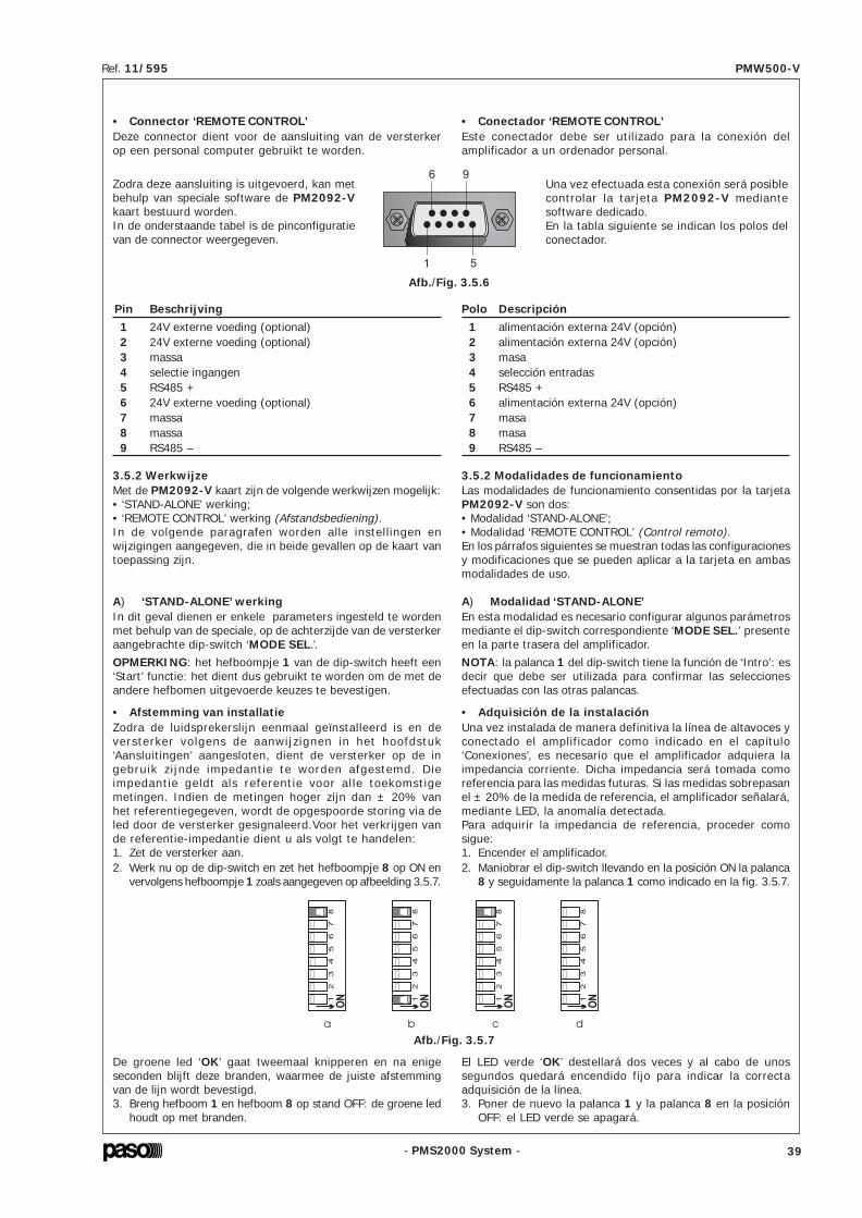
- PMS2000 System -
Ref. 11/595 PMW500-V
- PMS2000 System -
Ref. 11/595 PMW500-V
4. USO DELL’APPARECCHIO4.1 AccensionePrima di mettere in funzione l’apparecchio accertarsi di averrealizzato tutte le connessioni necessarie al completamentodell’impianto. Portare l’interruttore di rete [4] in posizione ON.La spia luminosa ‘ON’ [2] confermerà l’accensione delloapparecchio.
4.2 DisplayI led [3] del pannello frontale, ad esclusione di quello relativoall’accensione dell’apparecchio [2] fungono da indicatori dellivello di uscita e/o da indicatori dello stato di funzionamentodell’amplificatore (vedi par. ‘Display a led’. pagina 10).
5. NOTE DI SERVIZIO5.1 Ventilazione forzataL’unità di potenza PMW500-V dispone di due ventole per ilraffreddamento forzato degli stadi finali di potenza e dell’internodell’apparecchio. Queste ventole, asservite da un proprio circuitodi alimentazione e controllo, si attivano automaticamente alraggiungimento di una determinata temperatura del dissipatoredi calore e si arrestano quando la temperatura ritorna a livellinormali. In pratica, in condizioni d’uso tipiche per amplificatoridi questa caratura, quali la diffusione di musica di sottofondointervallata da annunci vocali a piena potenza, ed in condizioniclimatiche normali, la ventilazione forzata non si rendenecessaria e non viene quindi attivata; ciò comporta unanotevole riduzione dell’usura meccanica delle parti in movimento,la riduzione dell’accumulo di polvere introdotta nell’apparecchiodalle ventole e, non ultimo, la riduzione del rumore ambientalecausato dall’elevato numero di ventole in rotazione nel caso diimpianti con uno o più armadi contenenti un gran numero dibooster. Le ventole aspirano aria fresca dalle feritoie posterioridell’apparecchio [9] ed espellono l’aria riscaldata dalle feritoieanteriori [1], pertanto, è indispensabile che le feritoie nonvengano in alcun modo ostruite.
5.2 Condizioni di sovreccarico e protezioniIl modello PMW500-V dispone, oltre alla protezione classicaofferta dai fusibili, di una protezione elettronica e di una termicache lo salvaguarda da eventuali rischi di danneggiamento.Applicare un valore di impedenza di carico inferiore a quellanominale significa richiedere all’apparecchio una potenzasuperiore a quella erogabile con continuità.Questo potrebbe portare al danneggiamento degli stadi finali dipotenza e del trasformatore di uscita.Per non incorrere in questi inconvenienti l’amplificatore del sistemamodulare sono dotati di circuito di protezione contro i sovraccarichicon ripristino automatico. Il circuito di protezione interverràimmediatamente sull’amplificatore qualora si verificasse uno deiseguenti casi:- cortocircuito su una delle uscite per altoparlanti.- impedenza di carico inferiore al 50% del valore nominale.- potenza richiesta dal sistema di diffusori, collegati sulle linee
a tensione costante, superiore a quella erogabiledall’amplificatore.
La condizione di sovraccarico é segnalata dall’accensione,intermittente, della spia luminosa ‘OVD’ [3] posta sul pannellofrontale dell’apparecchio. L’apparecchio riprenderà il regolarefunzionamento non appena si sarà provveduto a rimuovere lacausa del sovraccarico. La protezione termica, anch’essa di tipoautoripristinante, interviene nel caso che l’apparecchio raggiungauna temperatura eccessiva dovuta, per esempio, ad unatemperatura ambiente troppo elevata o ad una scarsa aerazionedell’armadio rack.Durante l’intervento della protezione termica l’amplificatoresmetterà di funzionare, tutti i led si spegneranno e rimarranno infunzione soltanto le ventole.
4. USING THE EQUIPMENT4.1 Switching onBefore starting up the equipment, make sure that all theappropriate connections have been made to complete thesystem. Position the main power switch [4] in the ON position.The ‘ON’ [2] signalling lamp will confirm that the equipmenthas been switched on.
4.2 DisplayWith the exception of the LED indicating the on or off status ofthe equipment [2], the LEDs [3] on the front panel can act asindicators of the output level and/or of the operating status ofthe amplifier (see point ‘LED display’ on page 10).
5. SERVICE NOTES5.1 Forced ventilationModel PMW500-V boosters have a fan for the forced coolingof the final power stages and of the inside of the equipment.This fan, controlled by its own power-supply and control circuit,is activated automatically when the heat-sink reaches a giventemperature and turns off once the temperature has returnedto the normal level. In practice, in typical conditions of use foramplifiers of this size, such as the broadcasting of backgroundmusic with full-power voice announcement at intervals, andin normal climatic conditions, forced ventilation is not necessaryand will therefore not be activated. This leads to a considerablereduction in the mechanical wear rate of the moving parts, areduction in the accumulation of dust introduced inside theequipment by the fan and, last but not least, a reduction inthe environmental noise caused by the high number of fansthat would be running in case of systems with one or morecabinets containing a large number of boosters.The fan takes in cool air through the slits on the rear of theequipment [9] and expels the heated air through the slits infront [1]. It is therefore essential that these slits should notbe obstructed in any way.
5.2 Overload conditions and protection devicesIn addition to the usual protection consisting of fuses, thePMW500-V boosters have an electronic protection device anda thermal protection device in order to safeguard them frompossible risks of damage. Applying a lower loading impedancethan the rated value means requiring the equipment to supplya power higher than it can do on a continuous basis.This could cause damage to the final power stages and to theoutput transformer.In order to avoid these problems, the amplifiers of the modularsystem are equipped with protection circuits against overloads,with automatic reinstatement.The protection circuit will be tripped immediately on the amplifierif any of the following cases occurs:- short circuit on one of the loudspeaker outputs;- loading impedance less than 50% of the rated value;- power required of the loudspeaker system connected to
the constant-voltage lines higher than the power that theamplifier is able to deliver.
Overload conditions are signalled by the fact that the ‘OVD’signalling lamp [3] located on the front panel of the equipmentwill start to flash. The equipment will resume normal operationas soon as the cause of the overload has been eliminated.The thermal protection is also of the self-resetting type, andis tripped when the equipment reaches an excessively hightemperature. This may be due, for example, to the fact thatthe ambient temperature is too high or to the insufficientventilation of the rack cabinet.When the thermal protection is tripped, the amplifier will stopworking, all the LED's will extinguish and only the fan willcontinue to run.
• Connector ‘REMOTE CONTROL’Deze connector dient voor de aansluiting van de versterkerop een personal computer gebruikt te worden.
3.5.2 WerkwijzeMet de PM2092-V kaart zijn de volgende werkwijzen mogelijk:• ‘STAND-ALONE’ werking;• ‘REMOTE CONTROL’ werking (Afstandsbediening).In de volgende paragrafen worden alle instellingen enwijzigingen aangegeven, die in beide gevallen op de kaart vantoepassing zijn.
A) ‘STAND-ALONE’ werkingIn dit geval dienen er enkele parameters ingesteld te wordenmet behulp van de speciale, op de achterzijde van de versterkeraangebrachte dip-switch ‘MODE SEL.’.OPMERKING: het hefboompje 1 van de dip-switch heeft een‘Start’ functie: het dient dus gebruikt te worden om de met deandere hefbomen uitgevoerde keuzes te bevestigen.
Pin Beschrijving1 24V externe voeding (optional)2 24V externe voeding (optional)3 massa4 selectie ingangen5 RS485 +6 24V externe voeding (optional)7 massa8 massa9 RS485 –
Zodra deze aansluiting is uitgevoerd, kan metbehulp van speciale software de PM2092-Vkaart bestuurd worden.In de onderstaande tabel is de pinconfiguratievan de connector weergegeven.
• Afstemming van installatieZodra de luidsprekerslijn eenmaal geïnstalleerd is en deversterker volgens de aanwijzignen in het hoofdstuk‘Aansluitingen’ aangesloten, dient de versterker op de ingebruik zijnde impedantie te worden afgestemd. Dieimpedantie geldt als referentie voor al le toekomstigemetingen. Indien de metingen hoger zijn dan ± 20% vanhet referentiegegeven, wordt de opgespoorde storing via deled door de versterker gesignaleerd.Voor het verkrijgen vande referentie-impedantie dient u als volgt te handelen:1. Zet de versterker aan.2. Werk nu op de dip-switch en zet het hefboompje 8 op ON en
vervolgens hefboompje 1 zoals aangegeven op afbeelding 3.5.7.
De groene led ‘OK’ gaat tweemaal knipperen en na enigeseconden blijft deze branden, waarmee de juiste afstemmingvan de lijn wordt bevestigd.3. Breng hefboom 1 en hefboom 8 op stand OFF: de groene led
houdt op met branden.
Afb./Fig. 3.5.6
Afb./Fig. 3.5.7
• Conectador ‘REMOTE CONTROL’Este conectador debe ser utilizado para la conexión delamplificador a un ordenador personal.
Una vez efectuada esta conexión será posiblecontrolar la tarjeta PM2092-V mediantesoftware dedicado.En la tabla siguiente se indican los polos delconectador.
Polo Descripción1 alimentación externa 24V (opción)2 alimentación externa 24V (opción)3 masa4 selección entradas5 RS485 +6 alimentación externa 24V (opción)7 masa8 masa9 RS485 –
3.5.2 Modalidades de funcionamientoLas modalidades de funcionamiento consentidas por la tarjetaPM2092-V son dos:• Modalidad ‘STAND-ALONE’;• Modalidad ‘REMOTE CONTROL’ (Control remoto).En los párrafos siguientes se muestran todas las configuracionesy modificaciones que se pueden aplicar a la tarjeta en ambasmodalidades de uso.
A) Modalidad ‘STAND-ALONE’En esta modalidad es necesario configurar algunos parámetrosmediante el dip-switch correspondiente ‘MODE SEL.’ presenteen la parte trasera del amplificador.NOTA: la palanca 1 del dip-switch tiene la función de ‘Intro’: esdecir que debe ser utilizada para confirmar las seleccionesefectuadas con las otras palancas.
• Adquisición de la instalaciónUna vez instalada de manera definitiva la línea de altavoces yconectado el amplificador como indicado en el capítulo‘Conexiones’, es necesario que el amplificador adquiera laimpedancia corriente. Dicha impedancia será tomada comoreferencia para las medidas futuras. Si las medidas sobrepasanel ± 20% de la medida de referencia, el amplificador señalará,mediante LED, la anomalía detectada.Para adquirir la impedancia de referencia, proceder comosigue:1. Encender el amplificador.2. Maniobrar el dip-switch llevando en la posición ON la palanca
8 y seguidamente la palanca 1 como indicado en la fig. 3.5.7.
El LED verde ‘OK’ destellará dos veces y al cabo de unossegundos quedará encendido fijo para indicar la correctaadquisición de la línea.3. Poner de nuevo la palanca 1 y la palanca 8 en la posición
OFF: el LED verde se apagará.
14 39

- PMS2000 System -
Ref. 11/595 PMW500-V
- PMS2000 System -
Ref. 11/595 PMW500-V
4. Riaccendere l'amplificatore e verificare che si accenda il ledverde ‘OK’.
5. Riportare in posizione OFF la leva 1: il led ‘OK’ si spegne.
6. Riportare in posizione OFF tutte le altre leve.
3.5.3 CalibrazionePoichè l'accoppiamento scheda-amplificatore può portare dellevariazioni di guadagno nell'ordine del 5%, è possibile (ma nonindispensabile) correggere tali variazioni effettuando lacalibrazione nel seguente modo:1. Collegare sulla linea di uscita una resistenza da 100 ohm di
adeguata precisione.2. Agendo sul dip-switch, portare in posizione ON le levette da
2 a 8 come indicato in figura 3.5.15.3. Portare in posizione ON la levetta 1 per confermare la scelta
ed attendere che il led verde ‘OK’ si accenda.4. Riposizionare la leva 1 su OFF.5. Riportare tutte le altre leve in posizione OFF.Con questa azione, il misuratore di impedenza effettuerà misureassolute.
Impostazione indirizzo • Address setting Calibrazione • Calibration
Fig. 3.5.14 Fig. 3.5.15
4. Switch the amplifier on again and check that the green ‘OK’LED lights up.
5. Return lever 1 to the OFF position: the ‘OK’ LED will extinguish.6. Return all the other levers to the OFF position.
3.5.3 CalibrationSince the amplifier-card connection may lead to variations ingain of the order of 5%, it is possible (but not essential) tocorrect these variations by carrying out a calibration as follows:1. Connect a suitably accurate 100 ohm resistor on the output
line.2. On the dip-switch, move levers from 2 to 8 to the ON
position, as shown in Figure 3.5.15.3. Move lever 1 to the ON position to confirm the choice and
wait for the green ‘OK’ LED to light up.4. Return lever 1 to the OFF position.5. Return all the other levers to the OFF position.After doing this, the impedance measurement device will carryout absolute measurements.
• Instelling van eeninterval tussen twee tests in
Om het gewenste testinterval in te stellen dienen de hefboompjes4 t/m 8 gebruikt te worden.Hefboom 2 geeft de ‘test time’ mode aan.Laten we bijvoorbeeld een interval van 5 seconden instellen:1. Breng hefboom 2 op stand ON;2. Breng hefboom 1 op stand ON (Start): de groene led ‘OK’
gaat blijvend branden.3. Breng hefboom 1 weer terug naar stand OFF en vervolgens
ook hefboom 2; de led houdt op met branden om aan te gevendat de instelling correct is uitgevoerd.
In afbeelding 3.5.8 staan de voorbeelden van de instelling vande meest voorkomende intervals.
0 = 5 sec. (min. interval/intervalo mínimo)
1 = 1 min
29 = 29 min
30 = 1 h (max. interval/intervalo máximo)
Raadpleeg voor de overige waarden de ‘Configuratietafel’ oppag. 47/48. Wanneer het gewenste interval is gekozen, herhaaltde versterker regelmatig de test. Hierdoor is het mogelijk omde werking van de versterker te bewaken en onmiddellijk na tegaan of er defecten of storingen op de lijn zijn.
• Display met led’sAls er geen storingen zijn, hebben de led’s op het frontpaneelvan de versterker de functie van VU-METER. In het geval vanten minste één storing, wordt de VU-METER-functie verlaten enwordt de opgespoorde storing door de led’s aangegeven (zietabel op pag. 49).
Fig. 3.5.8
2 = 2 min 31 = NO TEST
• Instelling geluidsvolumeWanneer het apparaat voor het eerst wordt aangezet, wordtde uitgangsvolumeregeling overgelaten aan de trimmer naastde led ‘OK’. Bovendien kan het volume van de versterker ookworden geregeld met een op afstand geplaatste potentiometer,of door middel van een seriële aansluiting met een van speciaalsoftware voorziene PC.
• Configuración delintervalo entre un test y el siguiente
Para configurar el intervalo de test deseado se deben utilizar laspalancas desde la 4 hasta la 8.La palanca 2 identifica el modo ‘test time’.Configurar por ejemplo un intervalo de 5 segundos:1. Poner la palanca 2 en la posición ON;2. Poner en la posición ON la palanca 1 (Intro): el LED verde
‘OK’ se enciende fijo.3. Poner de nuevo en la OFF la palanca 1 y seguidamente la
palanca 2; el LED se apaga para indicar que la configuraciónha sido adquirida correctamente.
En la figura 3.5.8 se muestran los ejemplos de configuración delos intervalos más comunes.
Para los otros valores consultar la ‘Tabla de configuración’ en lapág. 47/48. Una vez seleccionado el intervalo deseado, elamplificador repite periódicamente el test. Esto consentirámonitorizar el funcionamiento del amplificador y verificar entiempo real la presencia de averías o anomalías de la línea.
• Display de LEDsNo habiendo averías, los LEDs en el panel frontal del amplificadorhacen de VU-METER. Cuando hay por lo menos una avería, esabandonada la función VU-METER y los LEDs indican la averíaregistrada (ver la tabla en la pág. 49).
• Control de volumenAl primer encendido, la regulación del volumen de salida esconfiada al condensador de ajuste situado al lado del LED‘OK’. Es posible también controlar el volumen del amplificadorcon un potenciómetro situado a distancia o bien medianteenlace serie con un PC provisto del software correspondiente.
40 13

- PMS2000 System -
Ref. 11/595 PMW500-V
- PMS2000 System -
Ref. 11/595 PMW500-V
La selezione dell'ingresso può essere inoltre essere effettuataattraverso un'interruttore remoto: per fare ciò, è necessariocollegare un interruttore tra i pin 4 e 8 del connettore ‘REMOTECONTROL’ come mostrato in figura 3.5.11.
Per poter cambiare l’ingresso tramite interruttore remoto, èindispensabile selezionare per mezzo dei dip-switch l’ingressoXLR.
• Modalità di risparmio energeticoAttivando questa funzione l’amplificatore rimarrà in stand-by,consumando così una minima quantità di energia: il led ‘ON’lampeggia. La normale attività riprenderà nel momento in cuiverrà rilevato un segnale da uno dei due ingressi.
• Filtro ‘LOW CUT’Ai fini di migliorare l’intelligibilità del parlato, può essere sceltol’inserimento di un filtro per i toni gravi; l’utente dovrà anche inquesto caso utilizzare i dip-switch per attivare la funzione.
Aperto = XLRChiuso = Morsettiera
Opened = XLRClosed = Terminal strip
Fig. 3.5.11
Filtro • ON • Filter Filtro • OFF • Filter
Fig. 3.5.12
Low Power • ON Low Power • OFF
Fig. 3.5.13
B) Modalità ‘REMOTE CONTROL’ (Controllo remoto)Per la gestione tramite il controllo remoto, si rimanda alladocumentazione dei software relativi. Alla prima accensione,l'impostazione di fabbrica della scheda prevede che l'indirizzosia uguale a 1.
• Impostazione indirizzoPer cambiare indirizzo, procedere come segue:1. Spegnere l'amplificatore.2. Con l'aiuto di un matita, portare in posizione ON la levetta 1
e la levetta 2 come indicato in figura 3.5.14a.3. Effettuate queste operazioni utilizzare le levette da 3 a 8 per
impostare l'indirizzo desiderato (da 0 a 63), seguendo la tavoladi configurazione alle pagine 47/48.
The input can also be selected by means of a remote switch. Inorder to be able to do this, it is necessary to connect a switchbetween pins 4 and 8 of the ‘REMOTE CONTROL’ connector, asshown in Fig. 3.5.11.
In order to be able to change the input by means of the remoteswitch, it is essential to select the XLR input by means of thedip-switch.
• ‘LOW CUT’ FilterFor the purpose of improving the speech intelligibility, it is possibleto choose to include a filter for the bass tones. Again in this casethe user will have to use the dip-switch to activate the function.
• Energy-saving modeIf this function is activated, the amplifier will remain on stand-by, so that it will only use up a minimum quantity of power. The‘ON’ LED will flash. Normal activity will be resumed as soon as asignal on either of the two inputs is detected.
B) ‘REMOTE CONTROL’ modeFor management via a remote control, reference should be madeto the documentation concerning the software being used. Onswitching on the equipment for the first time, the address will beequal to 1 according to the factory setting of the card.
• Address assignmentTo change this address, proceed as follows:1. Switch off the amplifier.2. With the help of a pencil, move lever 1 and lever 2 to the
ON position as indicated in Figure 3.5.14a.3. Carry out these operations using levers from 3 to 8 to set
the required address (from 0 to 63), on the basis of theconfiguration table on pages 47/48.
Om de bron van de volumeregeling te selecteren, dienen dehefbomen van de dip-switch gebruikt te worden, zoalsaangegeven op afbeelding 3.5.9.
Potentiometer op afstand • Potenciómetro remoto • Trimmer •
• RS485 •
Afb./Fig. 3.5.9
• Selectie van ingangenDe ingangen kunnen op twee manieren functioneren:1) als geschakelde ingangen2) als gemengde ingangenIn de fabriek worden de twee ingangen in de gemengde modusingesteld (Mod. 2); indien ze beide aanwezig zijn, krijgt hetsignaal afkomstig uit de connectors IN/OUT [10] voorrang.Hierdoor is men, in het geval van ontruimingsinstallaties,verzekerd van de test van de versterker en de prioritaireverzending van alert- en/of ontruimingsberichten.Het instellen van de geschakelde modus dient, nadat hetapparaat is losgekoppeld van alle voedingsbronnen, plaats tevinden met behulp van de kaart en wel als volgt:1. verwijder het deksel van de versterker2. verwijder de jumper uit de connector CN7 (MIX) en steek
deze in connector CN6 (NO MIX).3. plaats het deksel terug.
1) als geschakelde ingangenDe bron van waaruit de versterker het signaal haalt kan wordenvastgesteld met behulp van de dip-switch. De gebruiker kan,naar gelang de behoefte, kiezen om de XLR bussen te gebruikenof de klemmenstrook CONTROL I/O. Wanneer het apparaatvoor het eerst wordt aangezet, selecteert de kaart automatischhet signaal van de XLR ingang (fabrieksinstelling). In afbeelding3.5.10 worden beide instellingen aangegeven. De met behulpvan de dip-switch tot stand gebrachte instelling wordtopgenomen in het niet-vluchtige geheugen en komt bij elkeaanschakeling weer terug.
Bussen • XLR • Tomas Klemmenbord • CONTROL I/O • Bornera
Afb./Fig. 3.5.10
Para seleccionar la fuente de la regulación de volumen, maniobrarlas palancas del dip-switch como indicado en la figura 3.5.9.
1) entradas en conmutaciónLa fuente de la cual el amplificador tomará la señal se puededeterminar mediante los dip-switch. El usuario puede elegir,según las exigencias, entre utilizar las tomas XLR o elterminal de conexión CONTROL I/O. Al primer encendido,la tarjeta selecciona automáticamente la señal de la entradaXLR (configuración de fábrica).En la figura 3.5.10 se muestran ambas configuraciones.La configuración efectuada mediante dip-switch es escritaen la memoria no-volátil y es reactivada a cada encendido.
• Selección de las entradasEl funcionamiento de las entradas puede asumir dosmodalidades:1) entradas en conmutación2) entradas en mezclaEl ajuste de fábrica prevé la mezcla de las dos entradas (Mod.2); si están presentes ambas, se da la prioridad a la señalprocedentes de los conectores IN/OUT [10]. Esto permite,en el caso de instalaciones de evacuación, garantizar el testdel amplificador y el envío prioritario de mensajes de alerta y/o de evacuación. Para programar la modalidad de conmutaciónes necesario, después de haber desconectado el aparato decualquier fuente de alimentación, actuar sobre la tarjeta comosigue:1. quitar la tapa del amplificador2. quitar el puente del conector CN7 (MIX) y ponerlo en el
conector CN6 (NO MIX).3. poner de nuevo la tapa en su sitio.
12 41

- PMS2000 System -
Ref. 11/595 PMW500-V
- PMS2000 System -
Ref. 11/595 PMW500-V
Per selezionare la sorgente della regolazione di volume, operaresulle levette del dip-switch come indicato nella figura 3.5.9.
Potenziometro remoto • Remote potentiometer • Trimmer •
• RS485 •
Fig. 3.5.9
• Selezione degli ingressiIl funzionamento degli ingressi può assumere due modalità:1) ingressi in commutazione.2) ingressi in miscelazione.L’impostazione di fabbrica prevede la miscelazione dei dueingressi (Mod. 2); qualora siano entrambi presenti, verrà datapriorità al segnale proveniente dai connettori IN/OUT [10].Questo consente, nel caso di impianti d’evacuazione, di garantireil test dell’amplificatore e l’invio prioritario di messaggi d’allertae/o d’evacuazione. Per impostare la modalità di commutazione, ènecessario, dopo aver disconnesso l’apparecchio da ogni fonte dialimentazione, intervenire sulla scheda come segue:1. togliere la copertura dell’amplificatore.2. togliere il jumper dal connettore CN7 (MIX) ed inserirlo nel
connettore CN6 (NO MIX).3. riposizionare la copertura.
1) ingressi in commutazioneLa sorgente da cui l’amplificatore preleverà il segnale può esseredeterminata tramite i dip-switch. L’utente potrà scegliere, aseconda delle esigenze, di utilizzare le prese XLR o lamorsettiera ‘CONTROL I/O’ [8].Alla prima accensione, la scheda seleziona automaticamente ilsegnale dall'ingresso XLR (impostazione di fabbrica). Nella figura3.5.10 sono indicate entrambe le impostazioni. L’impostazioneeffettuata tramite dip-switch verrà scritta nella memoria non-volatile e ripresentata ad ogni accensione.
Prese • XLR • Sockets Morsettiera • CONTROL I/O • Terminal strip
Fig. 3.5.10
To select the source of the volume control, position the levers ofthe dip-switch as indicated in Figure 3.5.9.
1) switched inputsThe source from which the amplifier will take the signal can bedetermined by means of the dip-switch. The user may choose,depending on his specific requirements, to use either the XLRsockets or the ‘CONTROL I/O’ terminal strip.When the equipment is switched on for the first time, the cardwill automatically select the signal from the XLR input (factorysetting). Both settings are shown in Figure 3.5.10. The settingmade by means of the dip-switch will be entered in the non-volatile memory and presented every time the equipment isswitched on.
• Selection of inputsThe inputs can function in two different modes:1) switched inputs.2) mixed inputs.The factory settings provide mixing of the two inputs (Mode2). If they are both present, priority will be given to the signalfrom the IN/OUT connectors [10].This means that in the case of evacuation systems, testing ofthe amplifier and the sending of alert and/or evacuationmessages as priorities are ensured.To set the switching mode, disconnect the equipment from allsources of power and proceed as follows on the card:1. remove the cover of the amplifier.2. remove the jumper from connector CN7 (MIX) and insert
it into connector CN6 (NO MIX).3. put the cover back into place.
De selectie van de ingang kan bovendien worden uitgevoerdvia een afstandsschakelaar: hiervoor dient er een schakelaartussen pin 4 en 8 van de connector ‘REMOTE CONTROL’aangesloten te worden, zoals aangegeven op afb. 3.5.11.
Om de ingang met behulp van de afstandsschakelaar te kunnenwijzigen, dient door middel van de dip-switch de XLR ingang teworden geselecteerd.
• Energiebesparende modeDoor het activeren van deze functie blijft de versterker stand-by,en verbruikt zo een minimum aan energie: de led ‘ON’ knippert.Het apparaat gaat weer gewoon werken zodra er een signaalwordt opgevangen bij één van de ingangen.
• ‘LOW CUT’ FilterOm de gesproken tekst beter verstaanbaar te maken, kan wordengekozen voor het inschakelen van een filter voor de lage tonen;de gebruiker dient ook in dat geval de dip-switch te gebruikenvoor het activeren van de functie.
Open = XLRGesloten = Klemmenbord
Abierto = XLRCerrado = Bornera
Afb./Fig. 3.5.11
Filter • ON • Filtro Filter • OFF • Filtro
Afb./Fig. 3.5.12
Low Power • ON Low Power • OFF
Afb./Fig. 3.5.13
B) ‘REMOTE CONTROL’ werking (Afstandsbediening)Voor het besturen door middel van de afstandsbediening wordtverwezen naar de documentatie over de betreffende software.Wanneer het apparaat voor het eerst wordt aangezet, is hetdoor de fabriek ingestelde adres van de kaart gelijk aan 1.
• AdrestoekenningOm het adres te wijzigen handelt u als volgt:1. Schakel de versterker uit.2. Zet met behulp van een potlood het hefboompje 2 en hefboompje
1 op stand ON, zoals aangegeven op afb. 3.5.14a.3. Zodra deze handelingen zijn uitgevoerd gebruikt u hefboompje
3 t/m 8 voor het instellen van het gewenste adres (0 t/m63), aan de hand van de configuratietabel op pag. 47/48.
La selección de la entrada puede ser efectuada tambiénmediante un interruptor remoto: para ello es necesario conectarun interruptor entre los polos 4 y 8 del conectador ‘REMOTECONTROL’ como mostrado en la fig. 3.5.11.
Para poder cambiar la entrada mediante el interruptor remotoes indispensable seleccionar la entrada XLR mediante los dip-switch.
• Filtro ‘LOW CUT’Para mejorar la claridad del habla se puede seleccionar laactivación de un filtro para los tonos graves; el usuario debe ental caso utilizar los dip-switch para activar la función.
• Modalidad de ahorro energéticoActivando esta función el amplificador queda en stand-by,consumiendo de tal manera una cantidad mínima de energía: elLED ‘ON’ destella. La actividad normal es reanudada tan prontoes detectada una señal en una de las dos entradas.
B) Modalidad ‘REMOTE CONTROL’ (Control remoto)Para la gestión mediante el control remoto se remite a ladocumentación de los software correspondientes.Al primer encendido, la configuración de fábrica de la tarjetaprevé que la dirección sea igual que 1.
• Asignación direcciónPara cambiar de dirección, proceder como sigue:1. Apagar el amplificador.2. Con un lápiz llevar en la posición ON la palanca 2 y la palanca
1, como mostrado en la figura 3.5.14a.3. Efectuadas estas operaciones utilizar las palancas desde
la 3 hasta la 8 para configurar la dirección deseada (de0 a 63), conforme a la tabla de configuración de la pág.47/48.
42 11

- PMS2000 System -
Ref. 11/595 PMW500-V
- PMS2000 System -
Ref. 11/595 PMW500-V
• Impostazione dell'intervallotra un test ed il successivo
Per impostare l'intervallo di test desiderato, devono essereutilizzate le levette da 4 a 8.La levetta 2 identifica il modo ‘test time’.Impostiamo ad esempio un intervallo di 5 secondi:1. Portare la levetta 2 in posizione ON;2. Portare in posizione ON la levetta 1 (Invio): il led verde ‘OK’ si
accende in modo fisso.3. Riportare in posizione OFF la leva 1 e successivamente la leva
2; il led si spegne indicando che l'impostazione è stataacquisita correttamente.
Riportiamo nella figura 3.5.8 gli esempi dell’impostazione degliintervalli più comuni.
0 = 5 sec. (intervallo minimo/minimum interval)
1 = 1 min
29 = 29 min
30 = 1 h (intervallo massimo/maximum interval)
Per gli altri valori, consultare la ‘Tavola di configurazione’ allepagine 47/48. Una volta scelto l' intervallo desiderato,l'amplificatore ripeterà periodicamente il test. Questo consentiràdi monitorare il funzionamento dell'amplificatore e di verificarein tempo reale la presenza di guasti o anomalie della linea.
• Display a ledIn assenza di guasti, i led sul pannello frontale dell'amplificatorefungono da VU-METER. Qualora vi sia almeno un guasto, lafunzione VU-METER viene abbandonata e i led indicheranno ilguasto rilevato (vedi tabella a pag. 49).
Fig. 3.5.8
2 = 2 min 31 = NO TEST
• Controllo di volumeAlla prima accensione, la regolazione del volume di uscita vieneaffidata al trimmer posto a lato del led ‘OK’. È possibile inoltrecontrollare il volume dell'amplificatore con un potenziometro postoa distanza oppure tramite collegamento seriale con un pc dotatodi apposito software.
• Setting the intervalbetween one test and the next
Levers 4 to 8 have to be used for setting the required testinginterval.Lever 2 identifies the ‘test time’ mode.For example, to set an interval of 5 seconds:1. Move lever 2 to the ON position;2. Move lever 1 to the ON position (Enter): the green ‘OK’ LED
will light up steadily.3. Return lever 1 and then lever 2 to the OFF position.
The LED will extinguish to show that the setting has beencorrectly acquired.
Figure 3.5.8 shows examples referred to setting the mostcommonly used intervals.
For the other values, consult the ‘Configuration Table’ on pages47/48. Once the required interval has been chosen, the amplifierwill repeat the test periodically. This will make it possible tomonitor operation of the amplifier and to check the presence ofany failures or upsets in the line in real time.
• LED displayIf there are no failures, the LEDs on the front panel of theamplifier act as VU-METERs. If there is at least one failure, theVU-METER function is abandoned and the LEDs will indicate thefailure that has been detected (see table on page 49).
• Volume controlWhen the equipment is switched on for the first time, adjustmentof the output volume is made by means of a trimmer situatednext to the ‘OK’ LED. It is also possible to control the volume ofthe amplifier by means of a potentiometer situated in a remotelocation or by means of a signalling link to a PC in which aspecific software has been installed.
4. Zet de versterker weer aan en ga na of de groene led ‘OK’gaat branden.
5. Breng hefboom 1 op OFF: de led ‘OK’ gaat uit.6. Breng alle andere hefbomen op de OFF stand.
3.5.3 AfstellenDaar de combinatie kaart-versterker variaties kan veroorzakenin de orde van 5%, kunnen die variaties (maar dit is nietnoodzakelijk) gecorrigeerd worden door het apparaat als volgtaf te stellen:1. Sluit een resistentie van 100 ohm met een adequate
nauwkeurigheid aan op de lijn.2. Zet hefboompjes 2 t/m 8 op de dip-switch op ON, zoals
aangegeven op afbeelding 3.5.15.3. Breng hefboompje 1 op de ON stand om uw keuze te
bevestigen en wacht tot de groene led ‘OK’ gaat branden.4. Breng hefboom 1 weer op OFF.5. Breng alle andere hefboompjes weer op de OFF stand.Met deze handeling brengt het impedantie-meetapparaatabsolute meetwaarden tot stand.
Adrestoekenning • Asignación dirección Afstellen • Calibrado
Afb./Fig. 3.5.14 Afb./Fig. 3.5.15
4. Encender de nuevo el amplificador y comprobar que seencienda el LED verde ‘OK’.
5. Poner de nuevo en la posición OFF la palanca 1: el LED ‘OK’se apaga.
6. Poner de nuevo en la posición OFF todas las otras palancas.
3.5.3 CalibradoDado que la conexión tarjeta-amplificador puede conllevar unasvariaciones de ganancia del orden del 5%, es posible (perono indispensable) corregir dichas variaciones efectuando elcalibrado como sigue:1. Conectar en la línea de salida una resistencia de 100 ohm
de precisión adecuada.2. Maniobrando el dip-switch, llevar en la posición ON las palancas
desde la 2 hasta la 8 como mostrado en la fig. 3.5.15.3. Llevar en la posición ON la palanca 1 para confirmar la
selección y esperar que el LED verde ‘OK’ se encienda.4. Poner de nuevo la palanca 1 en OFF.5. Poner de nuevo en la posición OFF todas las otras palancas.Con esta acción el medidor de impedancia efectúa medidasabsolutas.
10 43

- PMS2000 System -
Ref. 11/595 PMW500-V
- PMS2000 System -
Ref. 11/595 PMW500-V
• Connettore ‘REMOTE CONTROL’Questo connettore deve essere utilizzato per il collegamentodell’amplificatore ad un personal computer.
3.5.2 Modalità di funzionamentoLe modalità di funzionamento consentite dalla scheda sono due:• Modalità ‘STAND-ALONE’;• Modalità ‘CONTROLLO REMOTO’Nei paragrafi seguenti verranno illustrate tutte le impostazioni ele modifiche che possono essere applicate alla scheda in entrambele modalità d’uso.
A) Modalità ‘STAND-ALONE’In questa modalità, è necessario impostare alcuni parametritramite l'apposito dip-switch ‘MODE SEL.’ presente sulposteriore dell'amplificatore.NOTALa levetta 1 del dip-switch svolge la funzione di ‘Invio’: deveessere cioè utilizzata per dare conferma delle scelte effettuatecon le altre leve.
Pin Descrizione1 alimentazione esterna 24V (opzionale)2 alimentazione esterna 24V (opzionale)3 massa4 selezione ingressi5 RS485 +6 alimentazione esterna 24V (opzionale)7 massa8 massa9 RS485 –
Una volta effettuata questa connessione,sarà possibile controllare tramite softwarededicato la scheda PM2092-V.Nella tabella sottostante è riportata lapiedinatura del connettore.
• Acquisizione dell'impiantoUna volta installata in modo definitivo la linea di altoparlantie collegato l 'amplif icatore come indicato nel capitolo‘Connessioni’, è necessario che l'amplificatore acquisiscal'impedenza corrente. Tale impedenza verrà presa comeriferimento per le misurazioni future.Qualora le misure superino i l ± 20% della misura diriferimento, l'amplificatore segnalerà tramite led l'anomaliarilevata. Per acquisire l'impedenza di riferimento, procedere nelseguente modo:1. Accendere l'amplificatore.2. Operare sul dip-switch portando in posizione ON la levetta 8 e
successivamente la levetta 1 come indicato in figura 3.5.7.
Il led verde ‘OK’ lampeggierà due volte e dopo alcuni secondirimarrà acceso in modo fisso ad indicare la corretta acquisizionedella linea.3. Riportare la leva 1 e la leva 8 in posizione OFF: il led verde si
spegne.
Fig. 3.5.6
Fig. 3.5.7
• ‘REMOTE CONTROL’ ConnectorThis connector has to be used to connect the amplifier to apersonal computer.
Once this connection has been made, it willthen be possible to control the PM2092-Vcard by means of dedicated software.The following table shows the pinout of theconnector.
Pin Description1 24V external power supply (optional)2 24V external power supply (optional)3 GND4 inputs selection5 RS485 +6 24V external power supply (optional)7 GND8 GND9 RS485 –
3.5.2 Operating modesThere are two possible operating modes enabled by the card:• ‘STAND-ALONE’ mode;• ‘REMOTE CONTROL’ mode.The settings and the changes that can be applied to the card ineach of the operating modes are described in the followingparagraphs.
A) ‘STAND-ALONE’ modeIn this mode, it is necessary to set some parameters using the‘MODE SEL.’ dip-switch provided for this purpose on the rearof the amplifier.NOTELever 1 of the dip-switch has an ‘Enter’ function. That is to say,it has to be used to confirm the choices opted for with the otherlevers.
• Acquisition of the systemOnce the loudspeaker line has been permanently installed, andthe amplifier has been connected as indicated in the chapteron ‘Connections’, it is necessary for the amplifier to acquire thecurrent impedance. This impedance value will be used as areference for the future measurements. If the results of themeasurements exceed the reference value by ± 20%, theamplifier will signal the problem that has been detected bymeans of the LED. To acquire the reference impedance value,proceed as follows:1. Switch on the amplifier.2. Operate the dip-switch by moving lever 8 to the ON position
and then lever 1 as shown in Figure 3.5.7.
The green ‘OK’ LED will then flash twice, and after a few secondsit will remain on steadily to indicate that the line has beencorrectly acquired.3. Return lever 1 and lever 8 to their OFF positions.
The green LED will extinguish.
4. GEBRUIK VAN HET APPARAAT4.1 InschakelingAlvorens het apparaat in werking te stellen, dient u zich ervan teverzekeren dat u alle voor het systeem benodigde aansluitingentot stand heeft gebracht. Zet de netschakelaar [4] op de standON. Het controlelampje ‘ON’ [2] geeft aan dat het apparaat isingeschakeld.
4.2 DisplayMet uitzondering van de led die aangeeft dat het apparaat isingeschakeld [2], kunnen de led’s [3] op het frontpaneel hetuitgangsniveau en/of de functietoestand van de versterkeraangeven (zie par. ‘Display met led’s. pagina 40).
5. OPMERKINGEN5.1 Geforceerde ventilatieDe versterkers PMW500-V zijn uitgerust met een ventilatorvoor de geforceerde koeling van de laatste vermogenstrappenen van het binnenste van het apparaat. Deze ventilator, diebeschikt over een eigen voedings- en besturingscircuit, treedtautomatisch in werking bij het bereiken van een bepaaldetemperatuur van de warmtewisselaar en schakelt uit wanneerde temperatuur weer op een normale waarde komt. In de praktijkis bij standaard gebruikscondities van dit soort versterkers, datwil zeggen de verspreiding van achtergrondmuziek afgewisseldmet gesproken mededelingen op vol vermogen, en bij normaleklimatologische omstandigheden, geforceerde ventilatie niet nodigen wordt deze dan ook niet ingeschakeld; dit leidt tot eenaanzienlijke reductie van de mechanische slijtage van debewegende delen, een vermindering van de hoeveelheid stofdie door de ventilator in het apparaat wordt gevoerd en, niet opde laatste plaats, een vermindering van het omgevingslawaaiveroorzaakt door het grote aantal draaiende ventilatoren in hetgeval van systemen met één of meer kasten met een grotehoeveelheid boosters. De ventilator zuigt frisse lucht aan doorde openingen op de achterzijde van het apparaat [9] en voertde verwarmde lucht af via de openingen op de voorzijde [1];het is dan ook van het grootste belang dat deze openingennooit geblokkeerd worden.
5.2 Overbelasting en beveiligingenDe PMW500-V zijn niet alleen uitgerust met de traditionelebeveiliging door middel van zekeringen, maar beschikken ook overeen elektronische beveiliging en een thermische beveiliging diehet apparaat beschermen tegen het risico van eventuelebeschadigingen. Toepassing van een lagere belastingsimpedantiedan de nominale waarde betekent dat aan het apparaatvoortdurend een hoger vermogen wordt gevraagd dan het op kanbrengen. Hierdoor kunnen de eindvermogenstrappen en deuitgangstransformator beschadigd raken. Om dergelijke problemente voorkomen, zijn de versterkers van het modulaire systeemuitgerust met een beveiligingscircuit tegen overbelasting metautomatische reset. Het beveiligingscircuit zal onmiddellijk inwerking treden indien zich één van de volgende situaties voordoet:- kortsluiting op één van de uitgangen voor luidsprekers.- belastingsimpedantie lager dan 50% van de nominale waarde.- vermogen dat gevraagd wordt door het systeem van
luidsprekers, aangesloten op de constante spanningslijnen,hoger dan het vermogen dat de versterker kan leveren.
De overbelastingsconditie wordt aangegeven door dat hetcontrolelampje ‘OVD’ [3] op het frontpaneel van het apparaatgaat knipperen. Het apparaat zal de normale werking hervattenzo gauw men de oorzaak van de overbelasting heeftweggenomen. De thermische beveiliging, die eveneens over eenautomatische reset beschikt, treedt in werking in het geval hetapparaat een te hoge temperatuur bereikt, bijvoorbeeld als gevolgvan een te hoge omgevingstemperatuur of een onvoldoendeventilatie van de kast. Wanneer de thermische beveiliginggeactiveerd wordt, stopt de versterker met werken, alle led'sgaan uit en alleen de ventilator blijft in werking.
4. USO DEL APARATO4.1 ENCENDIDOAntes de encender el aparato es preciso comprobar que todaslas conexiones necesarias para completar la instalación hayansido realizadas correctamente. Poner el interruptor de red [4]en la posición ON. El piloto luminoso ‘ON’ [2] confirma elencendido del aparato.
4.2 DisplayLos LEDs [3] del panel frontal, salvo el correspondiente alencendido del aparato [2], pueden actuar como indicadoresdel nivel de salida y/o como indicadores del estado defuncionamiento del amplificador (ver apartado ‘Display de LEDs,página 40).
5. NOTAS DE SERVICIO5.1 Ventilación forzadaLos amplificadores PMW500-V disponen de un ventilador paraenfriar de manera forzada las etapas finales de potencia y elinterior del aparato.Este ventilador, con su proprio circuito de alimentación ycontrol, se activa automáticamente cuando se alcanza unadeterminada temperatura en el disipador de calor y se detienecuando la temperatura vuelve a n ive les normales.Prácticamente, en condiciones de uso normales paraamplificadores de este calibre, como la difusión de músicaambiente con intercalados anuncios vocales a plena potencia,y en condiciones climáticas normales, la ventilación forzadano es necesaria por lo que no es activada; esto conlleva unareducción notable del desgaste mecánico de las partes enmovimiento, la reducción de la acumulación de polvointroducida en el aparato por los ventiladores y también lareducción del ruido ambiente causado por el alto número deventiladores en movimiento en el caso de instalaciones conuno o más armarios que contengan un gran número de booster.El ventilador aspira aire fresco por las ranuras traseras delaparato [9] y expulsa el aire caliente por las ranuras delanteras[1], por lo tanto es preciso no tapar nunca dichas ranuras.
5.2 Condiciones de sobrecarga y proteccionesEl PMW500-V dispone, además que de la protección clásicaproporcionada por los fusibles, de una protección electrónica yde una térmica que los protegen contra eventuales riesgos dedaños. Aplicar un valor de impedancia de carga inferior a lanominal significa pedir al aparato una potencia superior a laproporcionable con continuidad.Esto puede llevar a dañar las etapas finales de potencia y eltransformador de salida.Para no correr estos riesgos los amplificadores del sistemamodular disponen de circuito de protección contra lassobrecargas con restablecimiento automático. El circuito deprotección interviene inmediatamente sobre el amplificador enel caso de que se produzca uno de los casos siguientes:- cortocircuito en una de las salidas para altavoces.- impedancia de carga inferior al 50% del valor nominal.- potencia requerida por el sistema de difusores, conectados
en las l íneas de tensión constante, superior a lasuministrable por el amplificador.
La condición de sobrecarga queda señalada por el encendido,intermitente, del piloto luminoso ‘OVD’ [3] situado en el panelfrontal del aparato. El aparato vuelve a funcionar normalmentetan pronto se haya procedido a eliminar la causa de la sobrecarga.La protección térmica, también ella del tipo con autoresta-blecimiento, interviene cuando el aparato alcanza unatemperatura excesiva debida, por ejemplo, a una temperaturaambiente demasiado alta o a una escasa ventilación del armariorack. Durante la intervención de la protección térmica elamplificador cesa de funcionar, todos los LED se apagan y quedaen función sólo el ventilador.
44 9

- PMS2000 System -
Ref. 11/595 PMW500-V
- PMS2000 System -
Ref. 11/595 PMW500-V
• Collegamento ingressi (opzionale)Qualora si volesse collegare un secondo ingresso, utilizzare iterminali 8, 9 e 10 della morsettiera ‘CONTROL I/O’ [8] comemostrato in figura 3.5.2.
• Potenziometro remotoIl potenziometro remoto deveessere collegato ai terminali6, 7 e 8 del la morsettiera‘CONTROL I/O’ [8].
Fare riferimento alla figura 3.5.5per incrementare o decrementareil volume.
Fig. 3.5.5
• Collegamento alla linea altoparlantiCollegare il terminale 1 della morsettiera ‘CONTROL I/O’ [8]all’uscita di potenza 100 V. La linea altoparlanti deve essereinvece collegata al terminale 2 (vedi figura 3.3.3, pag. 6).
Fig. 3.5.2
C
O
N
T
R
O
L
I
/
OTO SPEAKER LINE
TO POWER OUTPUT
RELAY
NORMAL OPEN
COMMON
NORMAL CLOSED
V max 100V
I max 3A
IN +INPUT
LINE
IN -10
9
1
2
8
7
6
5
4
3
REMOTE VOL.
min. 10K LIN.
IN –
IN +C
O
N
T
R
O
L
I
/
OTO SPEAKER LINE
TO POWER OUTPUT
RELAY
NORMAL OPEN
COMMON
NORMAL CLOSED
V max 100V
I max 3A
IN +INPUT
LINE
IN -10
9
1
2
8
7
6
5
4
3
REMOTE VOL.
min. 10K LIN.
• Collegamento relèCome riportato sul pannello posteriore dell’amplificatore, icollegamenti del relè sono quelli illustrati in figura 3.5.3.
• Funzionamento del relèLe modalità di funzionamento del relè sono tre.La prima (MODE 0 - impostazione di fabbrica) prevede che ilrelè sia sempre eccitato e si disecciti solo per mancanza dialimentazione o guasto all’amplificatore. In questa modalità èpossibile, tramite l’utilizzo della scheda PM2095, impostareun sistema di più amplificatori con l’inserzione automatica diuna o più riserve. La seconda modalità (MODE 1), il relè èsempre eccitato e si diseccita solo in presenza di un guastosulla linea degli altoparlanti. Nella terza modalità (MODE 2), ilrelè è sempre eccitato e si diseccita se vi è un guasto di linea odell’amplificatore.
• Impostazione della modalità di funzionamentoViene di seguito illustrata la sequenza da effettuare per impostarele diverse modalità tramite il dip-switch della scheda. Le levevanno azionate in modo sequenziale (non simultaneo).
Fig. 3.5.3
d
51
23
4
ON
67
8
a
51
23
4
ON
67
8
b
51
23
4
ON
67
8
c
51
23
4
ON
67
8
MODE 0
da
51
23
4
ON
67
8
b
51
23
4
ON
67
8
c
51
23
4
ON
67
8
51
23
4
ON
67
8
MODE 1
da
51
23
4
ON
67
8
b
51
23
4
ON
67
8
c
51
23
4
ON
67
8
51
23
4
ON
67
8
MODE 2
C
O
N
T
R
O
L
I
/
OTO SPEAKER LINE
TO POWER OUTPUT
RELAY
NORMAL OPEN
COMMON
NORMAL CLOSED
V max 100V
I max 3A
IN +INPUT
LINE
IN -10
9
1
2
8
7
6
5
4
3
REMOTE VOL.
min. 10K LIN.
Volume
–
Volume
+
Fig. 3.5.4
• Connecting the inputs (optional)If you wish to connect a second input, use terminals 8, 9 and 10of the ‘CONTROL I/O’ terminal strip [8], as shown in Figure3.5.2.
• Connection to the loudspeakers lineConnect terminal 1 of the ‘CONTROL I/O’ terminal strip [8] tothe 100 V power output. The loudspeaker line has instead to beconnected to terminal 2 (see Figure 3.3.3, page 6).
• Connecting the relayAs shown on the rear panel of the amplifier, the connections forthe relay are those illustrated in Figure 3.5.3.
• Operation of the relayThere are three operation modes of the relay.In the first mode (MODE 0 – factory setting), the relay is alwaysexcited and is de-energized only if it is not powered or in theevent of a failure of the amplifier. In this mode, a systemconsisting of several amplifiers, with automatic switching ofone or more stand-by units, can be set using the PM2095card. In the second mode (MODE 1), the relay is always excitedand is de-energised only in the event of a failure on theloudspeaker line. In the third mode (MODE 2), the relay isalways excited and is de-energised if there is a line or anamplifier failure.
• Setting the operating modeThe sequence to be carried out to set the various modes bymeans of the dip-switch on the card is illustrated below.he levers must be lowered in sequence (not simultaneously).
• Remote potentiometerThe remote potentiometer has tobe connected to terminals 6, 7and 8 of the ‘CONTROL I/O’terminal strip [8].
Refer to Figure 3.5.5 for raisingor lowering the volume
5.3 AfstellingenDeze handeling mag alleen worden uitgevoerd doorgekwalificeerde technici die over de juiste apparatuurbeschikken. Afstelling is alleen nodig na een reparatie van debetroffen versterkingstrappen, bijvoorbeeld in het geval er éénof meer eindtransistoren zijn vervangen.1- Stel P101 (met warmtewisselaar op omgevingstemperatuur)
af tot er een spanning van 6mV wordt gemeten op deuiteinden van R110.
2- Stel P151 (met warmtewisselaar op omgevingstemperatuur)af tot er een spanning van 6mV wordt gemeten op deuiteinden van R160.
5.3 AjustesEsta operación puede ser efectuada sólo por parte depersonal técnico cualificado que disponga de los aparatosnecesarios. Se requiere el ajuste exclusivamente después deuna reparación de las etapas de amplificación afectadas; porejemplo en caso de sustitución de uno o varios transistores finales.1- Ajustar P101 (con disipador a temperaturas ambiente) hasta
medir una tensión de 6 mV en los cabos de R110.
2- Ajustar P151 (con disipador a temperaturas ambiente) hastamedir una tensión de 6 mV en los cabos de R160.
6. TECHNISCHE KENMERKEN 6. CARACTERÍSTICAS TÉCNICAS
Nom inale uitgangsverm ogen 500 W Potencia de salida nom inal
Gelijkspanningsuitgangen 100, 70, 50, 90 V(20, 9.4, 5, 16 Ω) Salidas a tensión constante
Vervorm ing bij nom inaal vermogen < 1% Distorsión a la potencia nom inal
Frequentie filteronderbreking (Low Cut) 320 Hz ± 20 Hz Frequencia de corte del filtro (Low Cut)
Vmax relè 100 V Vmax relais
A ctiveringsdrem pel (Mod. Low Power) ~ 55 mV Um bral de activación (Mod. Low Power)
A fleesdrempel 20 kHz (ingang) ~ 30 mV Um bral de lectura 20 kHz (entrada)
SER IËLE C OMM U NIC A T IE • R S485 • C OMU NIC A C IÓN SER IE
Snelheid 19200 bit/s Velocidad
Verzendwijze 8 bit Modalidad de transm isión
Pariteitsbit no Bit de paridad
Stop bit 1 Stop bit
INGA NGEN XLR • ENT R A DA S XLR
Gevoeligheid/im pedantie 775 mV 100 kΩ Sensib ilidad/impedancia
Verhouding signaal/storing > 80 dB Relaci ón señal/ruido
Respons in frequentie 50 ÷ 20000 Hz (0/-3 dB) Respuesta en frequencia
INGA NG KLEMST ROOK • ENT RA DA BORNERO
Gevoeligheid/im pedantie 720 mV 100 kΩ Sensib ilidad/impedancia
Verhouding signaal/storing > 80 dB Relaci ón señal/ruido
Respons in frequentie 50 ÷ 20000 Hz (0/-3 dB) Respuesta en frequencia
BEDIJFSOMT A NDIGHEDEN • CONDICIONES DE FUNCIONA MIENT O
Netvoeding 230 V ± 10% 50 / 60 Hz A lim entación desde la red
Elektriciteitsverbruik (@ 230 Vca) 950 W / 1150 VA Consum o de potencia (@ 230 Vca)
Externe gelijkstroomvoeding 22 ÷ 28 V A lim entación externa en c.c.
Stroom verbruik (@ 22÷28 Vcc) 25 A (MA X) Consum o de corriente (@ 22÷28 Vcc)
A fmetingen 482 x 133 x 420 mm Dim ensiones
Gew icht 25 kg Peso
Bedrijfs /Opslagtem peratuur
-10°C ÷ +45°C-40°C ÷ +70°C
Tem peratura operativa /Temperatura de alm acenaje
Relatieve vochtigheid < 90 % Hum edad relativa
Overeenkomstig de veiligheidsnorm CEI EN 60065 Seguridad conform e a norm a
8 45

- PMS2000 System -
Ref. 11/595 PMW500-V
- PMS2000 System -
Ref. 11/595 PMW500-V
3.4 Scheda traslatore di lineaPer installare questo accessorio è necessario rimuovere lacopertura dell’apparecchio. Dopo aver identificato il connettoreCN204 (part. [A], fig. 3.4.1)occorrerà rimuovere i ponticellicortocircuitanti in esso inseriti eposizionare, al loro posto, lascheda TM92.
Richiudere l’unità riposizionandola copertura.
Fig. 3.4.1
Fig. 3.5.1
3.5.1 ConnessioniLa morsett iera ‘CONTROL I/O ’[8] presente sul pannello posterioredell’amplificatore deve essere usata pereffettuare le principali connessioni.
3.5 Scheda di controlloAll’interno dell’amplificatore viene di serie montata la scheda dicontrollo PM2092-V, che è stata creata per consentirel'esecuzione semplice e veloce di test sull’ amplificatore stessoe della/e linee altoparlanti tramite l’utilizzo delle schedePM2094-V.Questa scheda gestisce tutte le funzioni dell'amplificatore, dagliingressi alla diagnostica ed è in grado di eseguire le seguentifunzioni:• misure di impedenza di linea;• diagnostica dell'amplificatore;• verifica dell’integrità della linea altoparlanti (PM2094-V).• verifica isolamento di terra (GND FAULT);• controllo di volume (locale o tramite potenziometro remoto);• selezione di due ingressi;• controllo del relè di potenza;• possibilità di inserimento del filtro LOW CUT;• funzionamento in modalità di risparmio energetico ‘LOW POWER’.La scheda può inoltre essere controllata tramite interfacciaseriale. Oltre ad eseguire tutte le operazioni e/o verificheimpostate localmente con i dip-switch, sarà possibile visualizzaree modificare tutti i parametri tra cui:• lettura dell'impedenza di riferimento per il test;• valore minimo e massimo entro cui il test risulta valido;• lettura dello stato dei test;• test dell'ingresso;• misura della temperatura dei transistor finali;• regolazione del volume;• comando remoto del relè.
C
O
N
T
R
O
L
I
/
OTO SPEAKER LINE
TO POWER OUTPUT
RELAY
NORMAL OPEN
COMMON
NORMAL CLOSED
V max 100V
I max 3A
IN +INPUT
LINE
IN -10
9
1
2
8
7
6
5
4
3
REMOTE VOL.
min. 10K LIN.
numero diffusori =833 Ω20 Ω
= 41
Esempio: si utilizzino un amplificatore PMW500-V con diffusoriche presentano una impedenza nominale pari a 833 ohm(corrispondenti ad una potenza di 12 watt su linea a 100 volt).Dalla tabella 3.3.1 si trova che l’impedenza nominale della lineadi uscita a 100 volt è pari a 20 ohm. Quindi:
Example: a PMW500-V booster with loudspeakers that have arated impedance of 833 ohm (corresponding to an output powerof 12 watt on a 100 volt line) is used. Based on table 3.3.1 it canbe seen that the rated output of the output line at 100 volt isequal to 20 ohm. Therefore:
number of loudspeakers =833 Ω20 Ω
= 41
3.4 Line transformer cardTo install this accessory, it is necessary to remove the cover ofthe equipment. After identifying connector CN204 (item [A],
Fig. 3.4.1), the short-circuitingjumpers in place on it will have tobe removed and a TM92 cardinserted in their place.
Close the unit by putting the coverback into place.
3.5 Control cardA PM2092-V is mounted inside the amplifier as a standard.This card was designed specifically to enable simple and rapidtests to be carried out on the amplifier itself and on theloudspeaker line(s) using the PM2094-V card.
This card manages all the functions of the amplifier, from theinputs to diagnostics, and is capable of carrying out the followingfunctions:• line impedance measurements;• amplifier diagnostics;• check of the integrity of the loudspeaker line (PM2094-V).• check of insulation to earth (GND FAULT);• volume control (local or by means of a remote potentiometer);• selection of two inputs;• check of the power relay;• possibility of including the LOW CUT filter;• operation in the ‘LOW POWER’ energy-saving mode.The card can also be controlled via a serial interface.In addition to carrying out all the operations and/or checks setlocally by means of the dip-switch, it will also be possible todisplay and alter all the parameters, including the following:• reading of the reference impedance for the test;• minimum and maximum values between which the test is valid;• reading of the test status;• testing of the input;• measurement of the temperature of the end transistors;• volume adjustment;• remote control of the relay.
3.5.1 ConnectionsThe ‘CONTROL I/O’ terminal strip[8] on the rear panel of the amplifierhas to be used to make the mainconnections.
CI202 R2
30
CN
20
4
C218
R2
29
R2
16
R2
36 R2
33
C2
20
R2
08
D2
18
D2
19
R226 C217
X2
07
C219
CC
N2
02
PR201PR202
X208
A
8. LIJST VERVANGINGSONDERDELEN
7. ACCESSOIRES
Kaart lijntransformator ................................................. TM92
7. ACCESORIOS
Tarjeta trasladador de línea .......................................... TM92
8. LISTA DE LAS PIEZAS DE REPUESTO
Gezeefdrukt frontpaneel 36/2481-S1 Panel frontal serigrafiado
Samenstel vermogenskring (Links) 27/4253 Conjunto circuito de potencia (IZDA)
Samenstel vermogenskring (Rechts) 27/4254 Conjunto circuito de potencia (DCHA
Samenstel circuit besturingskaart 27/4340-V Conjunto circuito tarjeta control
Samenstel circuit stroombegrenzer 27/4356 Conjunto circuito limitador de corriente
Samenstel circuit Vu-Meter 27/4370 Conjunto circuito Vu-Meter
Samenstel circuit bedieningen en besturing 27/4575 Conjunto circuito de mandos y pilotaje
Voedingstransformator TF197 Transformador de alimentación
Uitgangstransformator TU138/16 Transformador de salida
Geprogrammeerde micro 01PMW1.2 Micro programado
Netschakelaar 19/113 Interruptor de red
Handvat 38/341-VNO Asa
Koelventilator VT7 Ventilador de enfriamiento
Gelijkrichterbrug 50 A – 200 V 16/73 Rectificador 50 A - 200 V
Elektrolitische condensator 10000µF 63V 649060103 Condensador electrolítico 10000µF 63V
Keramische condensator 2,2 nF 400V 709010222 Condensador cerámico 2.2 nF 400V
Transistor TIP35 17/79 Transistor TIP35
Transistor BD911 17/65 Transistor BD911
46 7

- PMS2000 System -
Ref. 11/595 PMW500-V
- PMS2000 System -
Ref. 11/595 PMW500-V
Fig. 3.3.3
numero diffusori =impedenza nominale diffusore
impedenza amplificatore
numero diffusori =500 W10 W
= 50
• Calcolo del numero di diffusori(tramite le potenze)
Si supponga di avere definito sia l’amplificatore (cioé la suapotenza di uscita) che il tipo di diffusore con relativa potenzaassorbita. In questo caso il massimo numero di diffusoricollegabile sulla linea é determinato dalla seguente formula:
Esempio: si utilizzino un amplificatore PMW500-V, in grado dierogare una potenza pari a 500 watt, con plafoniere da 10watt nominali. Per sapere quanti diffusori sono collegabili allalinea di uscita si calcola:
3.3.1 Sistemi a tensione costanteIn questo tipo di impianto, i diffusori, provvisti di trasformatoridi adattamento d’ impedenza, sono tutt i col legat i inderivazione al la l inea (vedi es. di Fig. 3.3.3). Questoparticolare rende di facile realizzazione l’impianto e, nel casoin cui un altoparlante dovesse per qualche motivo scollegarsidalla linea, il resto dell’impianto proseguirebbe nel suo regolarefunzionamento. Le tensioni costanti disponibili in uscitadall’amplificatore sono da 50, 70, 90 e 100 V. Per il correttodimensionamento dell’impianto (scelta della tensione di lineadell’apparecchio e selezione della potenza del diffusore) épossibile individuare diverse procedure, di seguito riportatecon esempi numerici.
potenza amplificatorepotenza diffusore
numero diffusori =
• Calcolo del numero di diffusori(tramite le impedenze)
Se il dato disponibile é l’impedenza del diffusore, il numeromassimo di diffusori collegabili ad una linea é:
• Connessione alle terminazioni di linea PM2094-VPer il controllo dell’integrità della linea altoparlanti, è necessariocollegare alla fine della linea stessa due schede PM2094-V comemostrato in figura 3.3.3.N.B.: le schede devono avere lo stesso indirizzo logico; devonoinoltre essere inseriti i jumper CN106 e CN107 (vedi librettorelativo).
MAINS RATING CONSUMPT.
500W RMS 950W230V
50/60Hz
FUSE
T 10 A
CONSUMPT. 800W24V
POWER AMPLIFIERPMW500-V
FUSE
MADE IN ITALY
C
O
N
T
R
O
L
I
/
OTO SPEAKER LINE
TO POWER OUTPUT
RELAY
NORMAL OPEN
COMMON
NORMAL CLOSED
V max 100V
I max 3A
IN +INPUT
LINE
IN -10
9
1
2
8
7
6
5
4
3
REMOTE VOL.
min. 10K LIN.
N.B.: in impianti d’evacuazione VES (Voice Evacuation System) èobbligatorio eseguire le connessioni degli altoparlanti come illustrato.
3.3.1 Constant-voltage systemsIn this type of system the loudspeakers, which are equippedwith impedance-matching transformers, are all connected bybranching them from the line (see example in Figure 3.3.3).This fact makes the system easy to create and, if any of theloudspeakers should be disconnected from the line for anyreason, the rest of the system would continue to functionproperly. The constant voltages available as outputs from theamplifier are 50, 70, 90 and 100 V. There are several possibleprocedures for sizing the system correctly (by choosing theline voltage of the equipment or by choosing the output powerof the loudspeaker). Numerical examples of these proceduresare provided below.
• Connection to PM2094-V line terminationsIn order to monitor the integrity of the loudspeaker line, twoPM2094-V cards shall be connected to the end of the line asshown in Figure 3.3.3.N.B.: The cards must have the same logical address, andjumpers CN106 and CN107 must also be in place (see theappropriate booklet).
• Calculating the number of loudspeakers(on the basis of the power output)
It is assumed that both the amplifier (that is to say its outputpower) and the type of loudspeaker with the relevant absorbedpower have both been defined. In this case the maximumnumber of loudspeakers that can be connected to the line isdetermined by means of the following formula:
number of loudspeakers =amplifier power
loudspeaker power
Example: a PMW500-V booster capable of delivering an outputpower equal to 500 watt is used, with ceiling fixtures rated at10 watt. To find out how many loudspeakers can be connectedto the output line, calculate the following:
number of loudspeakers =500 W10 W
= 50
• Calculating the number of loudspeakers(on the basis of the impedance values)
If the available datum is the impedance of the loudspeaker, themaximum number of loudspeakers that can be connected to aline is:
dove l’impedenza nominale dell’amplificatore é ricavabile dallatabella 3.3.1 (pag. 5).
number of loudspeakers =loudspeaker rated impedance
amplifier impedance
N.B.: It is compulsory in VES’s (Voice Evacuation System) to makethe connections of the loudspeakers as illustrated.
Where the rated impedance of the amplifier can be found intable 3.3.1 (page 5).
ENOIZARUGIFNOCIDALOVAT • ELBATNOITARUGIFNOC
AVEL1
AVEL2
AVEL3
AVEL4
AVEL5
AVEL6
AVEL7
AVEL8
OZZIRIDNISSERDDA
FFO FFO FFO FFO FFO FFO 0
FFO FFO FFO FFO FFO NO 1
FFO FFO FFO FFO NO FFO 2
FFO FFO FFO FFO NO NO 3
FFO FFO FFO NO FFO FFO 4
FFO FFO FFO NO FFO NO 5
FFO FFO FFO NO NO FFO 6
FFO FFO FFO NO NO NO 7
FFO FFO NO FFO FFO FFO 8
FFO FFO NO FFO FFO NO 9
FFO FFO NO FFO NO FFO 01
FFO FFO NO FFO NO NO 11
FFO FFO NO NO FFO FFO 21
FFO FFO NO NO FFO NO 31
FFO FFO NO NO NO FFO 41
FFO FFO NO NO NO NO 51
FFO NO FFO FFO FFO FFO 61
FFO NO FFO FFO FFO NO 71
FFO NO FFO FFO NO FFO 81
FFO NO FFO FFO NO NO 91
FFO NO FFO NO FFO FFO 02
FFO NO FFO NO FFO NO 12
FFO NO FFO NO NO FFO 22
FFO NO FFO NO NO NO 32
FFO NO NO FFO FFO FFO 42
FFO NO NO FFO FFO NO 52
FFO NO NO FFO NO FFO 62
FFO NO NO FFO NO NO 72
FFO NO NO NO FFO FFO 82
FFO NO NO NO FFO NO 92
FFO NO NO NO NO FFO 03
FFO NO NO NO NO NO 13
6 47

- PMS2000 System -
Ref. 11/595 PMW500-V
- PMS2000 System -
Ref. 11/595 PMW500-V
3. CONNESSIONI3.1 Criteri generaliPer un corretto funzionamento dell’apparecchio è opportunoosservare alcuni criteri di massima nell’esecuzione deicollegamenti:- evitare il posizionamento di cavi e di microfoni sul mobile
dell’apparecchio.- evitare di stendere le linee di segnale parallele a quelle di
rete; osservare una distanza minima di 30/40 cm.- posizionare le linee di ingresso e le linee di uscita distanti
tra loro.- posizionare i microfoni al di fuori dell’angolo di radiazione dei
diffusori sonori per evitare il fenomeno di reazione acustica(effetto Larsen).
3.2 Ingresso/uscita di lineaSul pannello posteriore dell’apparecchio sono disponibili leprese XLR d’ingresso/uscita [10] per segnali a livello linea (0 dB,775 mV) dell’unità di potenza; le prese sono parallelate peragevolare il collegamento in cascata di più unità di potenza.In fig. 3.2.1 sono riportate le connessioni a queste prese.L’ingresso dell’amplificatore è bilanciato elettronicamente; perparticolari esigenze come, ad esempio, nel caso di lunghi cavidi collegamento e/o forti campi elettromagnetici disturbanti,é possibile isolare galvanicamente l’ingresso dell’amplificatoretramite la scheda opzionale TM92, dotata di traslatore di linea(vedi paragrafo 3.4).
Fig. 3.2.1
1: schermo / shield2: segnale (lato caldo) / signal (warm side)3: segnale (lato freddo) / signal (cold side)
3.3 Uscite di potenzaLe uscite di potenza per i diffusori sono disponibili sullamorsettiera per impianti di distribuzione a tensione costante(50,70, 90 e 100 V) [6].In tabella 3.3.1 sono riportati i valori nominali d’impedenzariferiti alle prese d’uscite a tensione costante.
USCITA PMW500-V50 V 5 Ω
70 V 9,4 Ω
90 V 16 Ω
100 V 20 Ω
Tab. 3.3.1
• Regolazione del volumeLa regolazione del volume di uscita può essere effettuatasemplicemente agendo sull'apposito trimmer ‘LEVEL’ [11]posto sul lato posteriore dell'apparecchio. Ruotando con unpiccolo giravite in senso orario, il livello viene incrementato;ruotando in senso antiorario, il livello viene decrementato.
Fig. 3.3.2
IN/OUT
2 1
3
IN/OUT.
E
SEL 8
REMOTE CONTROL
LEVEL OK
3. CONNECTIONS3.1 General criteriaIn order to allow the equipment to work correctly, it is advisableto comply with a number of general criteria when making theconnections:- Avoid positioning cables or microphones on the cabinet of the
equipment.- Avoid laying the signal lines parallel to the power-supply lines.
Keep a minimum distance of 30/40 cm.- Position the input lines and the output lines at a distance from
one another.- In order to avoid acoustic feedback (the Larsen effect), position
the microphones out of the angle of coverage of theloudspeakers.
3.2 Line input/outputThe XLR input/output sockets [10] for the line-level signals(0 dB, 775 mV) of the power unit are located on the rearpanel of the equipment. The sockets are paralleled in order tofacilitate cascade connection of several power units. Figure3.2.1 shows the connections to these sockets. The input ofthe ampli f ier is e lectronical ly balanced. For specia lrequirements such as, for example, in case of long connectingcables and/or strong electromagnetic fields that causeinterference, it is possible to insulate the amplifier inputgalvanically using the optional TM92 card, equipped with aline transformer (see paragraph 3.4).
3.3 Power outputsThe power outputs for the loudspeakers are available on theterminal strips for constant-voltage distribution systems(50,70, 90 and 100 V) [6].Table 3.3.1 shows the rated impedance values referred to theconstant-voltage output sockets.
OUTPUT PMW500-V50 V 5 Ω
70 V 9,4 Ω
90 V 16 Ω
100 V 20 Ω
Tab. 3.3.1
• Volume controlThe output volume can be adjusted simply by turning the‘LEVEL’ trimmer [11] provided for this purpose on the rearside of the equipment. It can be turned with a smallscrewdriver. In a clockwise direction the volume is increasedwhile in an anticlockwise direction the volume is decreased.
AVEL1
AVEL2
AVEL3
AVEL4
AVEL5
AVEL6
AVEL7
AVEL8
OZZIRIDNISSERDDA
NO FFO FFO FFO FFO FFO 23
NO FFO FFO FFO FFO NO 33
NO FFO FFO FFO NO FFO 43
NO FFO FFO FFO NO NO 53
NO FFO FFO NO FFO FFO 63
NO FFO FFO NO FFO NO 73
NO FFO FFO NO NO FFO 83
NO FFO FFO NO NO NO 93
NO FFO NO FFO FFO FFO 04
NO FFO NO FFO FFO NO 14
NO FFO NO FFO NO FFO 24
NO FFO NO FFO NO NO 34
NO FFO NO NO FFO FFO 44
NO FFO NO NO FFO NO 54
NO FFO NO NO NO FFO 64
NO FFO NO NO NO NO 74
NO NO FFO FFO FFO FFO 84
NO NO FFO FFO FFO NO 94
NO NO FFO FFO NO FFO 05
NO NO FFO FFO NO NO 15
NO NO FFO NO FFO FFO 25
NO NO FFO NO FFO NO 35
NO NO FFO NO NO FFO 45
NO NO FFO NO NO NO 55
NO NO NO FFO FFO FFO 65
NO NO NO FFO FFO NO 75
NO NO NO FFO NO FFO 85
NO NO NO FFO NO NO 95
NO NO NO NO FFO FFO 06
NO NO NO NO FFO NO 16
NO NO NO NO NO FFO 26
NO NO NO NO NO NO 36
48 5

- PMS2000 System -
Ref. 11/595 PMW500-V
- PMS2000 System -
Ref. 11/595 PMW500-V
2. AVVERTENZE GENERALI2.1 InstallazioneTutti gli apparecchi PASO sono costruiti nel rispetto delle piùsevere normative internazionali di sicurezza ed in ottemperanzaai requisiti della Comunità Europea. Per un corretto ed efficaceuso dell’apparecchio è importante prendere conoscenza di tuttele caratteristiche leggendo attentamente le presenti istruzionied in particolare le note di sicurezza.Durante il funzionamento dell’apparecchio è necessarioassicurare un’adeguata ventilazione. Evitare di racchiuderel’apparecchio in un mobile privo di aerazione o di ostruirne lefessure di ventilazione.Evitare inoltre di tenere l’apparecchio in prossimità di sorgentidi calore (termosifoni, impianti di riscaldamento, ecc.).Prima dell’accensione assicurarsi che tutti gli ingressi e le uscitesiano correttamente collegati.
2.2 Alimentazione e messa a terraL’apparecchio è predisposto per il funzionamento con tensionedi rete a 230 V ± 10% 50/60 Hz. E’ prevista, in alternativa, lapossibilità di alimentare l’apparecchio con una tensione continuaesterna di 24V da applicare agli appositi morsetti ‘24V’ dellamorsettiera [5]. Tipicamente questa tensione proviene daaccumulatori mantenuti sotto carica in tampone ed entra infunzione soltanto in caso di emergenza; è necessario, in questocaso, prevedere l’uso di un relè esterno che connetta le batterieall’apparecchio solo quando viene a mancare l’alimentazione direte.L’apparecchio è protetto contro le inversioni di polarità.In accordo con le normative di sicurezza, l’ interruttore diaccensione [4] agisce solo sulla tensione di rete.
2.3 Note di sicurezzaOgni intervento all’interno dell’apparecchio, quale la selezionedi alcuni modi d’uso o l’applicazione di accessori, deve essereeffettuato solo da personale specializzato: la rimozione delcoperchio rende accessibili parti con rischio di scosse elettriche.Prima di rimuovere i pannelli di chiusura, accertarsi sempreche il cavo di rete sia staccato. Nel caso di accidentale cadutadi liquidi sull’apparecchio, staccare immediatamente la spinadi rete ed interpellare il centro di assistenza PASO più vicino.L’apparecchio é corredato di cavo di alimentazione con filo diterra ed il relativo terminale sulla spina di rete non deve essererimosso in alcun caso.Assicurarsi che la presa di corrente sia dotata di collegamentodi terra a norma di legge.
IMPORTANTE
I terminali marcati con il simbolo
sono attivi e pericolosi.Il cablaggio esterno collegato a questi terminali, DEVE essereeseguito esclusivamente da personale specializzato.
2. GENERAL WARNINGS2.1 InstallationAll PASO equipment is built according to the strictestinternational safety standards and complies with EuropeanCommunity requisites. In order to use the equipment correctlyand effectively, it is important to be aware of all its featuresby reading these instructions and in particular the notes onsafety carefully.While the equipment is working, it is necessary to ensureadequate ventilation. Avoid closing the equipment inside acabinet without ventilation and take care not to obstruct theventilation slits.Also avoid keeping the equipment near a source of heat(radiator, heating systems and so on).Before switching on the equipment, make sure that all theinputs and outputs are correctly connected.
2.2 Power supply and connection to earthThe equipment has provisions for operation with a mainsvoltage of 230 V ± 10% 50/60 Hz. As an alternative, it ispossible to power the equipment with an external continuousvoltage of 24V to be applied to the appropriate ‘24V’ terminalon the terminal strip [5].Typically, this voltage is taken from accumulators under floatcharged that only starts working in case of emergencies. Inthis case, it is necessary to envisage use of an external relayfor connecting the batteries to the equipment only when themains power supply fails.The equipment is protected against polarity inversions.In accordance with the safety regulations, the ON/OFF switch[4] is only effective for the mains power supply.
2.3 Safety notesAny work inside the equipment, such as selecting some of themodes of operation or applying accessories may only be carriedout by specialised personnel. On removing the cover, partsentailing a danger of electric shocks will be made accessible.Always make sure that the mains cable of the power-supplymodule is disconnected before removing the panels. If anyliquid is accidentally spilt on the equipment, disconnect themains cable immediately and contact the nearest PASO ServiceCentre. The equipment is supplied with its own power-supplycable with an earth wire. The relevant terminal on the mainsplug must never be removed, under any circumstances. Makesure that the power outlet has a connection to earth inaccordance with the law.
IMPORTANT
The terminals marked with the symbol
are active and dangerous.The external connections toward these terminals MUST becarried out by specialized personnel only.
4 49
!
" #$% &%#'(
!"#$
%&
!
'%
(("#$(
%&
%%)*
+,)-*
!"#$
%&
!
'%
(("#$
%&
.,
.,
%%% %!
%%/
0(/
1 2%%
1 2
% % %
%$)" )%$(* )%$(*)
- %
0/
3%3
33"#$
4%&
56(
!(("#$
76!/&5
- 3)
%*
%
3%3
33"#$
4%&
56(
!("#$
76!/&5
-.,%
.,0/
& 0%
89
!(%76/
-1 2
1 2%
&
%
8%76/
" )%$(+$ ,-)
/
%
%"#$
%%%
:
(
"#$
(
;%):*
0)*
%
%"#$
%%%
:
(
"#$
(
.,
.,/
%
<%-
/:
1 2
%
1 20
%<% =(
%/
.!/! !/0 !
!!! 1 !
- PMS2000 System -
Ref. 11/595 PMW500-V
- PMS2000 System -
Ref. 11/595 PMW500-V
1. DESCRIZIONE GENERALEL’unità di potenza PMW500-V, abbinata al sistema PMS2000è in grado di rispondere ai requisiti richiesti dalla normativa IEC60849 riguardante i sistemi per la gestione delle emergenze edell'evacuazione VES (Voice Evacuation System).
I componenti del sistema modulare contrassegnati dal suffisso‘-V’ in coda al codice del prodotto sono stati realizzati al fine dicorrispondere alla normativa sopraccitata.
1.1 Pannello frontale[1] Feritoie d’aerazione.[2] Spia d’accensione.[3] Display a led.[4] Interruttore di rete.
PMW500-V
dB
ON
-10
SPK
-3
OVL
-40
GND
-6
AMP.
0
HOT
ON
OFF
POWER
PROFESSIONAL
MODULAR SYSTEM
1 32 4
CAUTION:DISCONNECT POWERSUPPLY CORDBEFORE CHANGINGFUSE.
CAUTION:TO REDUCE THE RISKOF FIRE, REPLACEONLY WITH SAMETYPE FUSE.
MAINS RATING CONSUMPT.
500W RMS 950W
FUSE
V
230V
50/60Hz
FUSE
T 10 A
CONSUMPT. 800W24V
POWER AMPLIFIERPMW500-V
50V00
90V 70V 100V16 5 9,4 20
FUSE
32A
MADE IN ITALY
CAUTION: DO NOT OBSTRUCT OPENING !
IN/OUT IN/OUT
C
O
N
T
R
O
L
I
/
OTO SPEAKER LINE
TO POWER OUTPUT
RELAY
NORMAL OPEN
COMMON
NORMAL CLOSED
V max 100V
I max 3A
IN +INPUT
LINE
IN -10
9
1
2
8
7
6
5
4
3
REMOTE VOL.
min. 10K LIN.
.
MODE
SEL
1
8
REMOTE CONTROL
LEVEL OK
91011121314
5 6 7 8
1.2 Pannello posteriore[5] Morsettiera per alimentazione esterna in c.c.[6] Morsettiera per collegamento diffusori.[7] Dip-switch per impostazioni di funzionamento.[8] Morsettiera connessioni.[9] Feritoie d’aerazione.[10] Prese per ingresso/uscita di linea.[11] Regolazione del volume d’uscita.[12] Connettore per controllo remoto.[13] Spina di rete con fusibile incorporato.[14] Fusibile di protezione per alimentazione esterna in c.c.
1.1 Front panel[1] Louvers.[2] Power signalling lamp.[3] LED display.[4] Mains switch.
1.2 Rear panel[5] Terminal strip for external DC power supply.[6] Terminal strip for loudspeakers connection.[7] Dip-switch for operational settings.[8] Connections terminal strip.[9] Louvers.[10] Line input/output sockets.[11] Output volume controller.[12] Remote-control connector.[13] Mains plug with built-in fuse.[14] Fuse for protecting the DC power supply.
1. GENERAL DESCRIPTIONThe PMW500-V booster, combined with the PMS2000 system,is capable of meeting the requirements of IEC standard 60849concerning systems for managing emergencies and evacuation(VES - Voice Evacuation System).
The components of the modular system with the suffix ‘-V’ atthe end of their product codes were designed specifically forcompliance with the standard in question.
Garantie • Ce produit est garanti comme étant exempt de défauts de matières premières et de fabrication. La durée de la garantieest conforme aux normes en vigueur. Paso réparera gratuitement tout produit défectueux en garantie dès lors que l'anomalie sevérifiera dans le cadre d'une utilisation normale du produit. La garantie ne couvre donc pas les produits utilisés et installés de façonerronée, endommagés mécaniquement ou encore souillés par des liquides ou des agents atmosphériques. Le produit défectueuxdevra être envoyé à Paso franco de frais d'expédition et de réexpédition. La présente garantie n'en inclut aucune autre, explicite ouimplicite, et ne couvre pas les lésions ou dommages causés aux personnes ou aux choses. Pour plus d'informations sur la garantie,veuillez contacter le distributeur PASO de votre zone.Important! L'utilisateur devra présenter une preuve d'achat (facture ou récépissé) pour pouvoir bénéficier de l'assistance engarantie. Il devra par ailleurs fournir la date d'achat, le modèle et le numéro de série reportés sur l'appareil. Veuillez à cette finremplir le mémento des données demandées dans le cadre ci-dessous.
Garantie • Für dieses Produkt wird eine Garantie für Rohmaterialfehler und Montagefehler gewährt; die Garantiezeit unterliegt dengültigen gesetzlichen Bestimmungen. Paso repariert das garantierte Produkt kostenlos, wenn sich herausstellt, dass der Defektwährend des normalen Gebrauchs aufgetreten ist; die Garantie erstreckt sich demnach nicht auf Produkte, die falsch gebraucht undinstalliert oder mechanisch, durch Flüssigkeiten oder Umwelteinflüsse beschädigt wurden. Das defekte Produkt muss francoVersandkosten für den Hin- und Rücktransport zu und von Paso gesendet werden. Diese Garantie schließt keine weiteren, explizitenoder impliziten Leistungen und Folgeschäden an Personen, Gegenständen oder Unfälle ein. Bitte wenden Sie sich an PASO-Fachhandelin Ihrer Gegend, wenn Sie weitere Informationen zu dieser Garantie wünschen.
Wichtig! Der Kunde muss einen Verkaufsbeleg (Rechnung oder Quittung) vorlegen, wenn er Serviceleistungen, die unter dieGarantie fallen, in Anspruch nehmen möchte. Er muss zu diesem Zweck außerdem das Kaufdatum angeben sowie das Modell und dieSeriennummer, die auf dem Gerät vermerkt sind. Diese Daten müssen in den unten stehenden Textkasten eingetragen werden.
50 3
Avvertenze per lo smaltimento di questo prodotto ai sensi della Direttiva Europea 2002/96/ECAlla fine della sua vita utile il prodotto non deve essere smaltito insieme ai rifiuti urbani, ma deve essere consegnatopresso gli appositi centri di raccolta differenziata predisposti dalla Vostra amministrazione comunale, oppure presso irivenditori che forniscono questo servizio. Smaltire separatamente un rifiuto elettrico e/o elettronico (RAEE) consentedi evitare possibili conseguenze negative per l’ambiente e per la salute derivanti da un suo smaltimento inadeguatoe permette di recuperare i materiali di cui è composto al fine di ottenere un importante risparmio di energia e dirisorse. Su ciascun prodotto è riportato a questo scopo il marchio del contenitore di spazzatura barrato.
Garanzia • Questo prodotto è garantito esente da difetti nelle sue materie prime e nel suo montaggio; il periodo di garanziaè regolamentato dalle norme vigenti. La Paso riparerà gratuitamente il prodotto difettoso qui garantito se il difetto risulteràessersi verificato durante l’uso normale; la garanzia non si estende quindi a prodotti usati ed installati in modo errato, danneggiatimeccanicamente, danneggiati da liquidi o da agenti atmosferici. Il prodotto, risultato difettoso, dovrà essere inviato alla Pasofranco di spese di spedizione e ritorno. Questa garanzia non ne comprende altre, esplicite od implicite, e non comprende dannio incidenti conseguenti a persone o cose. Contattare i distributori PASO della zona per maggiori informazioni sulla garanzia.
Importante! L'utente ha la responsabilità di produrre una prova d'acquisto (fattura o ricevuta) se vuole servirsi dell'assistenzacoperta da garanzia. Dovrà inoltre fornire data di acquisto, modello e numero di serie riportati sull'apparecchio; a questoscopo, compilare come promemoria dei dati richiesti lo spazio in basso.
Questo prodotto è conforme alle Direttive della Comunità Europea sotto le quali lo stesso ricade.
Recommandations pour l'élimination du produit conformément à la Directive Européenne 2002/96/ECAu terme de son utilisation, le produit ne doit pas être éliminé avec les déchets urbains. L'appareil doit être remis à l'undes centres de tri sélectif agréés par l'administration communale ou à un revendeur assurant ce service. L'éliminationdifférenciée des appareils électroniques (WEEE) permet non seulement d'éviter les retombées négatives pourl'environnement et la santé dues à une élimination incorrecte, mais aussi de récupérer les matériaux qui le composentet permet ainsi d'effectuer d'importantes économies en termes d'énergie et de ressources. Pour rappeler l'obligationd'éliminer séparément les appareils électroniques, le produit porte le symbole d'un caisson à ordures barré.
Ce produit est conforme aux Directives de la Communauté européenne auxquelles il est soumis.
MODELLO / MODÈLE / MODELL: .....................................................................................................................................................
NUMERO DI SERIE / NUMÉRO DE SÉRIE / SERIENNUMMER: ...........................................................................................................
DATA D’ACQUISTO / DATE D'ACHAT/ DATUM DES ERWERBS: .........................................................................................................
Dieses Produkt entspricht den diesbezüglichen EU-Richtlinien.
Wichtiger Hinweis für die Entsorgung des produkts in übereinstimmung mit der EG-richtlinie 2002/96/EC Am Ende seiner Nutzzeit darf das Produkt nicht zusammen mit dem Siedlungsabfall beseitigt werden,sondern es muss bei den zu diesem Zweck von den städtischen Behörden eingerichteten Sammelstellen oder zuden Fachhändlern, die einen Rücknahmeservice anbieten, gebracht werden. Die getrennte Entsorgung von Elektro-und Elektronik-Altgeräten (WEEE - Waste Electric and Electronic Equipment) vermeidet mögliche negativeAuswirkungen auf die Umwelt und die Gesundheit infolge einer nicht vorschriftsmäßigen Entsorgung. Zudemwird die Wiederverwertung der Materialen, aus denen das Gerät besteht, ermöglicht, so dass eine bedeutendeEinsparung an Energie und Ressourcen erzielt wird. Aus diesem Grund ist das Produkt mit dem Symbol einerdurchgestrichenen Mülltonne gekennzeichnet.

- PMS2000 System -
Ref. 11/595 PMW500-V
- PMS2000 System -
Ref. 11/595 PMW500-V
IntroduzioneNel ringraziarVi per aver scelto un prodotto PASO, vogliamoricordarVi che la nostra azienda opera con sistema di qualitàcertificato. Tutti i nostri prodotti vengono pertanto controllati inogni fase della produzione per garantirVi la piena soddisfazionedel Vostro acquisto. Per ogni evenienza la garanzia coprirà, nelperiodo di validità, eventuali difetti di fabbricazione.Vi raccomandiamo di leggere attentamente le seguenti istruzionid’uso per sfruttare appieno le prestazioni offerte da questoprodotto e per evitare eventuali problemi.
IntroductionWhile thanking you for having chosen a PASO product, we wouldlike to remind you that our company works according to a certifiedQuality System. This means that all our products are checkedduring every phase of manufacturing in order to ensure that youwill be fully satisfied with your purchase. In any case, theguarantee will cover any manufacturing flaws during theguarantee period. We recommend that you read the followinginstructions for use and follow them carefully in order to exploitin full the performance of this product and use it correctly.
SOMMARIO
1. Descrizione generale .......................................... 31.1 Pannello frontale ...................................................... 31.2 Pannello posteriore ................................................... 3
2. Avvertenze generali ........................................... 42.1 Installazione ............................................................. 42.2 Alimentazione e messa a terra .................................. 42.3 Note di sicurezza ...................................................... 4
3. Connessioni ........................................................ 53.1 Criteri generali ......................................................... 53.2 Ingresso/uscita di linea ............................................. 53.3 Uscite di potenza ...................................................... 5
• Regolazione del volume ......................................... 53.3.1 Sistemi a tensione costante ...................................... 63.4 Scheda traslatore di linea ......................................... 73.5 Scheda di controllo ................................................... 73.5.1 Connessioni .............................................................. 7
• Collegamento alla linea altoparlanti ........................ 8• Collegamento ingressi (opzionale) .......................... 8• Collegamento relè ................................................. 8• Funzionamento del relè ......................................... 8• Impostazione della modalità di funzionamento ....... 8• Potenziometro remoto ........................................... 8• Connettore ‘REMOTE CONTROL’ ............................. 9
3.5.2 Modalità di funzionamento ........................................ 9a) Modalità ‘STAND-ALONE’ ...................................... 9
• Acquisizione dell’impianto ................................. 9• Impostazione dell’intervallo
tra un test ed il successivo .............................. 10• Display a led ................................................... 10• Controllo di volume ......................................... 10• Selezione degli ingressi ................................... 11• Filtro ‘LOW CUT’ ............................................. 12• Modalità di risparmio energetico ...................... 12
b) Modalità ‘REMOTE CONTROL’ ............................. 12• Impostazione indirizzo .................................... 12
3.5.3 Calibrazione ........................................................... 13
4. Uso dell’apparecchio ........................................ 144.1 Accensione ............................................................. 144.2 Display ................................................................... 14
5. Note di servizio ................................................ 145.1 Ventilazione forzata ................................................ 145.2 Condizioni di sovraccarico e protezioni .................... 145.3 Tarature ................................................................. 15
6. Caratteristiche tecniche ................................... 15
7. Accessori .......................................................... 16
8. Lista delle parti di ricambio ............................. 16
• Tavola di configurazione ...................................... 47/48
• Ricerca guasti ........................................................... 49
TABLE OF CONTENTS
1. General description ........................................... 31.1 Front panel .............................................................. 31.2 Rear panel ............................................................... 3
2. General warnings .............................................. 42.1 Installation .............................................................. 42.2 Power supply and connection to earth ..................... 42.3 Safety notes ............................................................ 4
3. Connections ....................................................... 53.1 General criteria ........................................................ 53.2 Line input/output ..................................................... 53.3 Power outputs ......................................................... 5
• Volume control ...................................................... 53.3.1 Constant-voltage systems ........................................ 63.4 Line transformer card .............................................. 73.5 Control card ............................................................. 73.5.1 Connections ............................................................. 7
• Connection to the loudspeakers line ...................... 8• Connecting the inputs (optional) ........................... 8• Connecting the relay ............................................. 8• Operation of the relay ........................................... 8• Setting the operating mode ................................... 8• Remote potentiometer .......................................... 8• ‘REMOTE CONTROL’ Connector ............................. 9
3.5.2 Operating modes ..................................................... 9a) ‘STAND-ALONE’ mode ......................................... 9
• Acquisition of the system ................................. 9• Setting the interval
between one test and the next ....................... 10• LED display .................................................... 10• Volume control ............................................... 10• Selection of inputs ......................................... 11• ‘LOW CUT’ Filter ............................................. 12• Energy-saving mode ....................................... 12
b) ‘REMOTE CONTROL’ Mode ................................. 12• Address assignment ....................................... 12
3.5.3 Calibration ............................................................. 13
4. Using the equipment ....................................... 144.1 Switching on .......................................................... 144.2 Display .................................................................. 14
5. Service notes ................................................... 145.1 Forced ventilation .................................................. 145.2 Overload conditions and protection devices ............ 145.3 Adjustments .......................................................... 15
6. Technical specifications .................................. 15
7. Accessories ....................................................... 16
8. List of spare parts ............................................ 16
• Configuration table ............................................. 47/48
• Failure conditions ..................................................... 49
2 51
MODEL / MODELO / MODEL: ..........................................................................................................................................................
SERIAL NUMBER / NÚMERO DE SERIE / SERIENUMMER: ................................................................................................................
PURCHASE DATE / FECHA DE COMPRA / AANKOOPDATUM: ............................................................................................................
Belangrijke informatie voor de verwerking van het product in overeenstemming met de EuropeseRichtlijn 2002/96/EC Aan het einde van zijn levensduur mag het product niet samen met het gewone huishoudelijkeafval worden verwerkt. Het moet naar het daartoe bestemde gemeentelijke verzamelpunt voor gescheiden afvalworden gebracht, of naar een verkooppunt dat deze service verleent. Het apart verwerken van afgedankte elektrischeen elektronische apparatuur (AEEA) voorkomt mogelijk negatieve gevolgen voor het milieu en de gezondheid diedoor een ongeschikte verwerking ontstaan en zorgt ervoor dat de materialen waaruit het apparaat is samengesteldteruggewonnen kunnen worden om een aanmerkelijke besparing van energie en grondstoffen te verkrijgen. Om opde verplichting tot gescheiden verwerking van elektrische apparatuur te wijzen, is op het product het symbool vaneen doorgekruiste vuilnisbak aangebracht.
Garantie • Dit product is gegarandeerd vrij van materiaal- en constructiefouten; de garantieduur wordt geregeld door de geldendewettelijke voorschriften. Paso voert de reparatie van de hier gegarandeerde defecte producten kosteloos uit, indien blijkt dat hetdefect tijdens normaal gebruik is opgetreden. De garantie heeft dus geen betrekking op verkeerd gebruikte of geïnstalleerdeproducten, producten die mechanisch beschadigd zijn of beschadigingen hebben opgelopen door vloeistoffen of de invloed vanweersomstandigheden. Producten waarbij een defect is geconstateerd dienen franco verzend- en retourkosten aan Paso opgestuurdte worden. Deze garantie omvat geen enkele andere expliciete of impliciete garantie en dekt geen schade aan personen of zaken.Voor verdere informatie over de garantie dient contact opgenomen te worden met de dichtstbijzijnde PASO distributeur.
Belangrijk! De gebruik(st)er is verantwoordelijk voor het overleggen van een aankoopbewijs (factuur of ontvangstbewijs), indien hij/zij gebruik wenst te maken van door de garantie gedekte assistentie. Bovendien moet hij/zij opgave doen van de aankoopdatum, hetmodel en serienummer, die op het apparaat zijn aangebracht. Vul daarom de gevraagde gegevens hieronder in, als geheugensteun.
Dit product is conform de Richtlijnen van de Europese Gemeenschap waaronder het valt.
Important information for disposal of the product in accordance with EC Directive 2002/96/ECThis product must not be disposed of as urban waste at the end of its working life. It must be taken to a special wastecollection centre licensed by the local authorities or to a dealer providing this service. Separate disposal of electricand/or electronic equipment (WEEE) will avoid possible negative consequences for the environment and for healthresulting from inappropriate disposal, and will enable the constituent materials to be recovered, with significantsavings in energy and resources. As a reminder of the need to dispose of this equipment separately, the product ismarked with a crossed-out wheeled dustbin.
Warranty • This product is warranted to be free from defects in raw materials and assembly. The warranty period is governed bythe applicable provisions of law. Paso will repair the product covered by this warranty free of charge if it is faulty, provided the defecthas occurred during normal use. The warranty does not cover products that are improperly used or installed, mechanically damagedor damaged by liquids or the weather. If the product is found to be faulty, it must be sent to Paso free of charges for shipment andreturn. This warranty does not include any others, either explicit or implicit, and does not cover consequential damage to propertyor personal injury. For further information concerning the warranty contact your local PASO distributor.
Important! Should the user wish to avail himself of servicing under the warranty, he must provide evidence of the purchase (invoiceor receipt). The user shall also indicate the date of purchase, model and serial number indicated on the equipment. For this reason,you should complete the box below as a reminder of the data required.
This product is in keeping with the relevant European Community Directives.
Advertencias para la eliminación correcta del producto según establece la Directiva Europea 2002/96/EC Al final de su vida útil, el producto no debe eliminarse junto a los residuos urbanos. Debe entregarse a centrosespecíficos de recogida selectiva establecidos por las administraciones municipales, o a los revendedores que facilitaneste servicio. Eliminar por separado un aparato eléctrico o electrónico (WEEE) significa evitar posibles consecuenciasnegativas para el medio ambiente y la salud derivadas de una eliminación inadecuada y permite reciclar los materialesque lo componen, obteniendo así un ahorro importante de energía y recursos. Para subrayar la obligación de eliminarpor separado el aparato, en el producto aparece un contenedor de basura móvil listado.
Este producto cumple con sus correspondientes Directivas de la Comunidad Europea.
Garantía • Este producto está garantizado libre de defectos en sus materias primas y en su montaje; el periodo de garantía se rigepor las normas vigentes. La Paso reparará gratuitamente el producto defectuoso aquí garantizado si el defecto resultará habersepresentado durante el uso normal; la garantía no ampara pues los productos utilizados e instalados de manera errónea, dañadosmecánicamente, dañados por líquidos o por agentes atmosféricos. El producto, que haya resultado defectuoso, deberá ser enviadoa la Paso con portes pagados de envío y de vuelta. Esta garantía no incluye otras, explícitas o implícitas, y no incluye daños oaccidentes consiguientes a personas o cosas. Contactar con los distribuidores PASO de la zona para más información acerca de lagarantía.
¡Importante! El usuario tiene la responsabilidad de presentar una prueba de compra (factura o recibo) si desea utilizar la asistenciaamparada por la garantía. Deberá así mismo demostrar la fecha de compra e indicar el modelo y el número de serie indicados en elaparato; con tal fin, rellenar como memorando de los datos necesarios el cuadro siguiente.

- PMS2000 System -
Ref. 11/595 PMW500-V
- PMS2000 System -
Ref. 11/595 PMW500-V
PMW500-V
SISTEMA MODULARE PROFESSIONALE PMS2000PMS2000 PROFESSIONAL MODULAR SYSTEM
Istruzioni per l’usoInstructions for useManuel d’utilisationGebrauchsanleitungGebruiksinstructiesInstrucciones de empleo
Unità di potenzaBoosterUnité de puissanceLeistungseinheitVermogenseenhedenUnidad de potencia
PMW500-V
dB
ON
-10
SPK
-3
OVL
-40
GND
-6
AMP.
0
HOT
ON
OFF
POWER
PROFESSIONAL
MODULAR SYSTEM
Via Mecenate, 90 - 20138 MILANO - ITALIATEL. +39-02-580 77 1 (15 linee r.a.)
FAX +39-02-580 77 277http://www.paso.it
Printed in Italy - 11/06 - 0.02K - 11/595
NOTALa PASO declina ogni responsabilità per danni a cose e/o persone derivanti dall'uso non corretto dell'apparecchio o da procedurenon rispondenti a quanto riportato sul presente libretto. Nel continuo intento di migliorare i propri prodotti, la PASO S.p.A. siriserva il diritto di apportare modifiche ai disegni e alle caratteristiche tecniche in qualsiasi momento e senza alcun preavviso.
NOTEPASO will not accept any liability for damage to property and/or persons arising out of incorrect use of the equipment or ofprocedures that do not comply with the instructions provided in this booklet. PASO S.p.A. strive to improve their productscontinuously, and therefore reserve the right to make changes to the drawings and technical specifications at any time andwithout notice.
NOTEPASO décline toute responsabilité en cas de dommages matériels et/ou physiques provoqués par l'utilisation impropre del'appareil ou encore par des opérations ou des interventions ne respectant pas les instructions figurant dans la présente notice.En raison de l’amélioration constante de ses produits, PASO S.p.A. se réserve le droit d’apporter des modifications aux dessinset caractéristiques techniques à tout instant et sans préavis aucun.
MERKEPASO lehnt jede Haftung für Schäden an Personen und / oder Gegenständen ab, die durch unzweckmäßige Verwendung oderVorgehen entstehen, die nicht den Anweisungen dieses Handbuches entsprechen. In der Überzeugung, die eigenen Produktebeständig verbessern zu wollen, behält sich PASO S.p.A. das Recht vor, jederzeit und ohne Vorankündigung Änderungen antechnischen Zeichnungen und - Merkmalen vorzunehmem.
OPMERKINGPASO kan niet aansprakelijk worden gesteld voor schade aan voorwerpen en/of persoonlijk letsel die het gevolg zijn van eenonjuist gebruik van het apparaat of van procedures die niet overeenkomen met de voorschriften uit deze handleiding. AangezienPASO S.p.A. voortdurend verbeteringen aanbrengt aan haar producten, behoudt zij zich het recht voor op ieder moment zondervoorbericht de tekeningen en technische eigenschappen aan wijzigen te onderwerpen.
NOTALa PASO rehusa cualquier responsabilidad ante daños a cosas y/o personas causados por una utilización no correcta del aparatoo por operaciones no conformes a cuanto indicado en este folleto. Siempre con la firme intención de mejorar sus productos, PasoS.p.A. se reserva el derecho de modificar los dibujos y las características técnicas, sin preaviso alguno.
52 1
S.p.A