
PMP 320 Administration and Configuration Guide -...
141
PMP 320 Administration and Configuration Guide PMP320ADMINCFG2vB OCT 2010 Access Point and Subscriber Module Release 2.0 © 2010 Motorola, Inc. All Rights Reserved.
Transcript of PMP 320 Administration and Configuration Guide -...

PMP 320 Administration and Configuration Guide
PMP320ADMINCFG2vBOCT 2010
Access Point and Subscriber Module
Release 2.0
© 2010 Motorola, Inc. All Rights Reserved.

Accuracy
While reasonable efforts have been made to assure the accuracy of this document, Motorola, Inc. assumes noliability resulting from any inaccuracies or omissions in this document, or from use of the information obtainedherein. Motorola, Inc. reserves the right to make changes to any products described herein to improve reliability,function, or design, and reserves the right to revise this document and to make changes from time to time in contenthereof with no obligation to notify any person of revisions or changes. Motorola, Inc. does not assume any liabilityarising out of the application or use of any product, software, or circuit described herein; neither does it conveylicense under its patent rights or the rights of others. It is possible that this publication may contain references to, orinformation about Motorola products (machines and programs), programming, or services that are not announcedin your country. Such references or information must not be construed to mean that Motorola intends to announcesuch Motorola products, programming, or services in your country.
Copyrights
This document, Motorola products, and 3rd Party Software products described in this document may includeor describe copyrighted Motorola and other 3rd Party supplied computer programs stored in semiconductormemories or other media. Laws in the United States and other countries preserve for Motorola, its licensors, andother 3rd Party supplied software certain exclusive rights for copyrighted material, including the exclusive rightto copy, reproduce in any form, distribute and make derivative works of the copyrighted material. Accordingly,any copyrighted material of Motorola, its licensors, or the 3rd Party software supplied material contained in theMotorola products described in this document may not be copied, reproduced, reverse engineered, distributed,merged or modified in any manner without the express written permission of Motorola. Furthermore, the purchaseof Motorola products shall not be deemed to grant either directly or by implication, estoppel, or otherwise, anylicense under the copyrights, patents or patent applications of Motorola or other 3rd Party supplied software,except for the normal non-exclusive, royalty free license to use that arises by operation of law in the sale of aproduct.
Restrictions
Software and documentation are copyrighted materials. Making unauthorized copies is prohibited by law. No partof the software or documentation may be reproduced, transmitted, transcribed, stored in a retrieval system, ortranslated into any language or computer language, in any form or by any means, without prior written permissionof Motorola, Inc.
License Agreements
The software described in this document is the property of Motorola, Inc and its licensors. It is furnished by expresslicense agreement only and may be used only in accordance with the terms of such an agreement.
High Risk Materials
Components, units, or 3rd Party products used in the product described herein are NOT fault-tolerant and are NOTdesigned, manufactured, or intended for use as on-line control equipment in the following hazardous environmentsrequiring fail-safe controls: the operation of Nuclear Facilities, Aircraft Navigation or Aircraft CommunicationSystems, Air Traffic Control, Life Support, or Weapons Systems (High Risk Activities). Motorola and its supplier(s)specifically disclaim any expressed or implied warranty of fitness for such High Risk Activities.
Trademarks
Motorola and the Stylized M Logo are registered in the US Patent & Trademark Office. All other product or servicenames are the property of their respective owners.
The CE mark confirms Motorola, Inc. statement of compliance with EU directives applicable to this product. Copiesof the Declaration of Compliance and installation information in accordance with the requirements of EN50385can be obtained from the local Motorola representative or by contacting the PMP 320 support team. The 24 hourtelephone numbers are listed in this manual in the Contacting Motorola section. Alternatively if you do not haveaccess to the PMP 320 support team or the internet, contact the Local Motorola Office.
OCT 2010

Tableof
Contents
Contents■ ■ ■ ■ ■ ■ ■ ■ ■ ■ ■ ■ ■ ■ ■ ■ ■ ■ ■ ■ ■ ■ ■ ■ ■ ■ ■ ■ ■ ■ ■ ■ ■ ■ ■ ■ ■ ■ ■ ■ ■ ■ ■ ■ ■ ■ ■ ■ ■ ■ ■ ■ ■ ■ ■ ■ ■ ■ ■ ■ ■
■
■
■
■
PMP 320 Hardware InstallationRevision history . . . . . . . . . . . . . . . . . . . . . . . . . . . . . . . . . . . . . . . . . 2
Version information . . . . . . . . . . . . . . . . . . . . . . . . . . . . . . . . . . . . . 2General information . . . . . . . . . . . . . . . . . . . . . . . . . . . . . . . . . . . . . . . 3
Purpose . . . . . . . . . . . . . . . . . . . . . . . . . . . . . . . . . . . . . . . . . . . 3Cross references . . . . . . . . . . . . . . . . . . . . . . . . . . . . . . . . . . . . . . . 3Document banner definitions . . . . . . . . . . . . . . . . . . . . . . . . . . . . . . . . 3Text conventions . . . . . . . . . . . . . . . . . . . . . . . . . . . . . . . . . . . . . . . 4
Contacting Motorola . . . . . . . . . . . . . . . . . . . . . . . . . . . . . . . . . . . . . . . 5Escalate the problem to the PMP 320 Support Team. . . . . . . . . . . . . . . . . . . . . 5
Chapter 1: Product DescriptionAccess Point (AP) . . . . . . . . . . . . . . . . . . . . . . . . . . . . . . . . . . . . . . . . 1-3
Site preparation . . . . . . . . . . . . . . . . . . . . . . . . . . . . . . . . . . . . . . . 1-5Cluster Management Module 4 (CMM4) . . . . . . . . . . . . . . . . . . . . . . . . . . . . . 1-6
What is included when the CMM4 unit is shipped . . . . . . . . . . . . . . . . . . . . . . 1-8Point to Multi-point Integrated Cluster Subscriber Module 320 . . . . . . . . . . . . . . . . . 1-9
Site considerations. . . . . . . . . . . . . . . . . . . . . . . . . . . . . . . . . . . . . . 1-10Point to Multi-point Connectorized Cluster Subscriber Module 320 . . . . . . . . . . . . . . . 1-11
Site considerations. . . . . . . . . . . . . . . . . . . . . . . . . . . . . . . . . . . . . . 1-12
Chapter 2: AP Hardware InstallationInstalling the AP Hardware . . . . . . . . . . . . . . . . . . . . . . . . . . . . . . . . . . . 2-2
Assembling the AP and attaching to a tower . . . . . . . . . . . . . . . . . . . . . . . . . 2-2Assembling the AP and connecting the antenna . . . . . . . . . . . . . . . . . . . . . . . 2-5Earth Ground cable assembly and connection . . . . . . . . . . . . . . . . . . . . . . . . 2-11LED indicator . . . . . . . . . . . . . . . . . . . . . . . . . . . . . . . . . . . . . . . . 2-14Attach the AP assembly to a pole . . . . . . . . . . . . . . . . . . . . . . . . . . . . . . 2-15Surge Suppression Information . . . . . . . . . . . . . . . . . . . . . . . . . . . . . . . 2-19AP Hardware Installation complete . . . . . . . . . . . . . . . . . . . . . . . . . . . . . 2-19
Chapter 3: CMM4 Hardware InstallationBefore you begin . . . . . . . . . . . . . . . . . . . . . . . . . . . . . . . . . . . . . . . . . 3-3
Avoiding Hazards . . . . . . . . . . . . . . . . . . . . . . . . . . . . . . . . . . . . . . 3-3Grounding Equipment . . . . . . . . . . . . . . . . . . . . . . . . . . . . . . . . . . . . 3-3Grounding Infrastructure Equipment . . . . . . . . . . . . . . . . . . . . . . . . . . . . 3-4Conforming to Regulations. . . . . . . . . . . . . . . . . . . . . . . . . . . . . . . . . . 3-4Protecting Cables and Connections . . . . . . . . . . . . . . . . . . . . . . . . . . . . . 3-4Testing the Components . . . . . . . . . . . . . . . . . . . . . . . . . . . . . . . . . . . 3-4Unpacking Components . . . . . . . . . . . . . . . . . . . . . . . . . . . . . . . . . . . 3-5
PMP320HDW2vB i
OCT 2010

Contents
Installation Overview . . . . . . . . . . . . . . . . . . . . . . . . . . . . . . . . . . . . . . 3-6Installing the GPS Antenna . . . . . . . . . . . . . . . . . . . . . . . . . . . . . . . . . . . 3-7
Recommended Tools for GPS Antenna Mounting. . . . . . . . . . . . . . . . . . . . . . . 3-7Mounting a GPS Antenna . . . . . . . . . . . . . . . . . . . . . . . . . . . . . . . . . . 3-7GPS Coax Cable . . . . . . . . . . . . . . . . . . . . . . . . . . . . . . . . . . . . . . . 3-8
Installing the power supply for the CMM4 . . . . . . . . . . . . . . . . . . . . . . . . . . . . 3-1056 VDC Power Supply Installation . . . . . . . . . . . . . . . . . . . . . . . . . . . . . . 3-1030 VDC Power Supply Installation . . . . . . . . . . . . . . . . . . . . . . . . . . . . . . 3-12
Surge Suppressors . . . . . . . . . . . . . . . . . . . . . . . . . . . . . . . . . . . . . . . . 3-13600SSD and 200SSB Surge Suppressor installation . . . . . . . . . . . . . . . . . . . . . 3-14L-COM Surge Suppressor installation . . . . . . . . . . . . . . . . . . . . . . . . . . . . 3-15
Installing the CMM4 . . . . . . . . . . . . . . . . . . . . . . . . . . . . . . . . . . . . . . . 3-17Cabling a CMM4 . . . . . . . . . . . . . . . . . . . . . . . . . . . . . . . . . . . . . . . 3-20LED indicators . . . . . . . . . . . . . . . . . . . . . . . . . . . . . . . . . . . . . . . . 3-23Power Faults . . . . . . . . . . . . . . . . . . . . . . . . . . . . . . . . . . . . . . . . . 3-24Configuring CMM4 ports . . . . . . . . . . . . . . . . . . . . . . . . . . . . . . . . . . 3-25Other Installation Considerations . . . . . . . . . . . . . . . . . . . . . . . . . . . . . . 3-25
Chapter 4: CablesDC Cables . . . . . . . . . . . . . . . . . . . . . . . . . . . . . . . . . . . . . . . . . . . . 4-2Ethernet Cables . . . . . . . . . . . . . . . . . . . . . . . . . . . . . . . . . . . . . . . . . 4-3CMM Sync Cable. . . . . . . . . . . . . . . . . . . . . . . . . . . . . . . . . . . . . . . . . 4-5AP default plug. . . . . . . . . . . . . . . . . . . . . . . . . . . . . . . . . . . . . . . . . . 4-7
Constructing a AP default plug. . . . . . . . . . . . . . . . . . . . . . . . . . . . . . . . 4-7
Chapter 5: Integrated CSM Hardware InstallationBefore you begin . . . . . . . . . . . . . . . . . . . . . . . . . . . . . . . . . . . . . . . . . 5-2
Additional material required for installation . . . . . . . . . . . . . . . . . . . . . . . . . 5-3Pre-installation planning . . . . . . . . . . . . . . . . . . . . . . . . . . . . . . . . . . . 5-3Components shipped with the Integrated CSM . . . . . . . . . . . . . . . . . . . . . . . 5-4Cabling Overview . . . . . . . . . . . . . . . . . . . . . . . . . . . . . . . . . . . . . . 5-5
Installing the Integrated CSM . . . . . . . . . . . . . . . . . . . . . . . . . . . . . . . . . . 5-7Selecting a location for the Integrated CSM . . . . . . . . . . . . . . . . . . . . . . . . . 5-7
Installation Overview . . . . . . . . . . . . . . . . . . . . . . . . . . . . . . . . . . . . . . 5-8Completing the mounting bracket assembly . . . . . . . . . . . . . . . . . . . . . . . . . 5-8Attaching the Integrated CSM and mounting the bracket assembly outside the building . . 5-9Fastening the Integrated CSM and mounting the bracket assembly to a pole . . . . . . . . 5-10
Aligning the Integrated CSM for best signal strength . . . . . . . . . . . . . . . . . . . . . . 5-12Connecting the Integrated CSM to the Ethernet cable, Earth Ground, the Surge Suppressor . . 5-14
Ethernet Cable Assembly . . . . . . . . . . . . . . . . . . . . . . . . . . . . . . . . . . 5-14Running cables through the wall of the building . . . . . . . . . . . . . . . . . . . . . . . . . 5-16Installing the 600SSD Surge Suppressor. . . . . . . . . . . . . . . . . . . . . . . . . . . . . 5-17
Connecting the ground wire . . . . . . . . . . . . . . . . . . . . . . . . . . . . . . . . . 5-18Connecting the power supply and the Ethernet cable to the computer. . . . . . . . . . . . 5-19
Chapter 6: Connectorized CSM Hardware InstallationBefore you begin . . . . . . . . . . . . . . . . . . . . . . . . . . . . . . . . . . . . . . . . . 6-3
Additional material required for installation . . . . . . . . . . . . . . . . . . . . . . . . . 6-3Pre-installation planning . . . . . . . . . . . . . . . . . . . . . . . . . . . . . . . . . . . 6-4Components shipped with the Connectorized CSM . . . . . . . . . . . . . . . . . . . . . 6-4Cabling Overview . . . . . . . . . . . . . . . . . . . . . . . . . . . . . . . . . . . . . . 6-6
Installation Overview . . . . . . . . . . . . . . . . . . . . . . . . . . . . . . . . . . . . . . 6-8Completing the mounting bracket assembly . . . . . . . . . . . . . . . . . . . . . . . . . 6-8Attaching the Connectorized CSM and mounting the bracket assembly outside thebuilding . . . . . . . . . . . . . . . . . . . . . . . . . . . . . . . . . . . . . . . . . . . 6-9
ii PMP320HDW2vB
OCT 2010

Contents
Fastening the Connectorized CSM and mounting the bracket assembly to a pole . . . . . . 6-10Connecting the Antenna Cables to the Unit . . . . . . . . . . . . . . . . . . . . . . . . . . . 6-12Connecting the Connectorized CSM to the Ethernet cable, Earth Ground, the SurgeSuppressor. . . . . . . . . . . . . . . . . . . . . . . . . . . . . . . . . . . . . . . . . . . . 6-14
Ethernet Cable Assembly . . . . . . . . . . . . . . . . . . . . . . . . . . . . . . . . . . 6-14Running cables through the wall of the building . . . . . . . . . . . . . . . . . . . . . . . . . 6-16Installing the 600SSD Surge Suppressor. . . . . . . . . . . . . . . . . . . . . . . . . . . . . 6-17
Connecting the ground wire . . . . . . . . . . . . . . . . . . . . . . . . . . . . . . . . . 6-18Connecting the power supply and the Ethernet cable to the computer. . . . . . . . . . . . 6-20
Chapter 7: Regulatory, Legal, and Safety NoticesIMPORTANT NOTE ON MODIFICATIONS . . . . . . . . . . . . . . . . . . . . . . . . . . . . 7-2NATIONAL AND REGIONAL REGULATORY NOTICES . . . . . . . . . . . . . . . . . . . . . . 7-3
U.S. Federal Communication Commission (FCC) Notification . . . . . . . . . . . . . . . . 7-3Industry Canada Notification . . . . . . . . . . . . . . . . . . . . . . . . . . . . . . . . 7-4European Union Notification. . . . . . . . . . . . . . . . . . . . . . . . . . . . . . . . . 7-6Equipment Disposal . . . . . . . . . . . . . . . . . . . . . . . . . . . . . . . . . . . . . 7-6EU Declaration of Conformity for RoHS Compliance. . . . . . . . . . . . . . . . . . . . . 7-7Labeling and Disclosure Table for China . . . . . . . . . . . . . . . . . . . . . . . . . . . 7-7
RF EXPOSURE SEPARATION DISTANCES. . . . . . . . . . . . . . . . . . . . . . . . . . . . 7-9Details of Exposure Separation Distances Calculations and Power Compliance Margins. . . 7-9
Software License Terms and Conditions . . . . . . . . . . . . . . . . . . . . . . . . . . . . . 7-11Hardware Warranty in US . . . . . . . . . . . . . . . . . . . . . . . . . . . . . . . . . . . . 7-14LIMIT OF LIABILITY . . . . . . . . . . . . . . . . . . . . . . . . . . . . . . . . . . . . . . . 7-15
PMP320HDW2vB iii
OCT 2010

Contents
iv PMP320HDW2vB
OCT 2010

Listof
Figures
List of Figures■ ■ ■ ■ ■ ■ ■ ■ ■ ■ ■ ■ ■ ■ ■ ■ ■ ■ ■ ■ ■ ■ ■ ■ ■ ■ ■ ■ ■ ■ ■ ■ ■ ■ ■ ■ ■ ■ ■ ■ ■ ■ ■ ■ ■ ■ ■ ■ ■ ■ ■ ■ ■ ■ ■ ■ ■ ■ ■ ■ ■
■
■
■
■
Figure 1-1: High Level Network Diagram . . . . . . . . . . . . . . . . . . . . . . . . . . . . 1-2Figure 1-2: Access Point (AP) shown with the antenna attached and mounted on pole. . . . . . 1-3Figure 1-3: AP, radio only . . . . . . . . . . . . . . . . . . . . . . . . . . . . . . . . . . . . 1-4Figure 1-4: CMM4 with door open . . . . . . . . . . . . . . . . . . . . . . . . . . . . . . . . 1-6Figure 1-5: Integrated CSM 320 Subscriber Module. . . . . . . . . . . . . . . . . . . . . . . 1-9Figure 1-6: Connectorized CSM 320 subscriber module . . . . . . . . . . . . . . . . . . . . . 1-11Figure 1-7: Connectorized CSM 320 rear view subscriber module . . . . . . . . . . . . . . . . 1-11Figure 2-1: Pipe Clamp Assembly Identification . . . . . . . . . . . . . . . . . . . . . . . . . 2-4Figure 2-2: AP and antenna parts with scissors bracket . . . . . . . . . . . . . . . . . . . . . 2-4Figure 2-3: LED location diagram . . . . . . . . . . . . . . . . . . . . . . . . . . . . . . . . 2-14Figure 2-4: Mounting the AP to the tower . . . . . . . . . . . . . . . . . . . . . . . . . . . . 2-15Figure 3-1: AP Installation and wiring . . . . . . . . . . . . . . . . . . . . . . . . . . . . . . 3-2Figure 3-2: 600SSD surge suppressor connectors . . . . . . . . . . . . . . . . . . . . . . . . 3-13Figure 3-3: 200SSD surge suppressor . . . . . . . . . . . . . . . . . . . . . . . . . . . . . . 3-14Figure 3-4: L-COM surge suppressor . . . . . . . . . . . . . . . . . . . . . . . . . . . . . . 3-15Figure 3-5: CMM4 unit opened showing connection details . . . . . . . . . . . . . . . . . . . 3-18Figure 3-6: CMM4 connection diagram located on the door of the unit . . . . . . . . . . . . . 3-20Figure 3-7: Port Status Showing Power Fault . . . . . . . . . . . . . . . . . . . . . . . . . . 3-25Figure 4-1: RJ-45 Straight-through connections . . . . . . . . . . . . . . . . . . . . . . . . . 4-4Figure 4-2: Pin 1 Location diagram . . . . . . . . . . . . . . . . . . . . . . . . . . . . . . . 4-4Figure 4-3: CMM sync cable pinouts. . . . . . . . . . . . . . . . . . . . . . . . . . . . . . . 4-6Figure 4-4: CMM sync cable pinouts. . . . . . . . . . . . . . . . . . . . . . . . . . . . . . . 4-6Figure 5-1: Integrated CSM (CPE) 320 Identification . . . . . . . . . . . . . . . . . . . . . . 5-1Figure 5-2: Integrated CSM components . . . . . . . . . . . . . . . . . . . . . . . . . . . . 5-5Figure 5-3: Integrated CSM mounted to a wall . . . . . . . . . . . . . . . . . . . . . . . . . 5-6Figure 5-4: Ethernet cable weather protection assembly . . . . . . . . . . . . . . . . . . . . 5-14Figure 5-5: Cable connections from the surge suppressor to the Integrated CSM power injectorand the Integrated CSM . . . . . . . . . . . . . . . . . . . . . . . . . . . . . . . . . . . . . 5-18Figure 5-6: Integrated CSM 320 power injector . . . . . . . . . . . . . . . . . . . . . . . . . 5-18Figure 6-1: Connectorized CSM (CPE) 320 Identification . . . . . . . . . . . . . . . . . . . . 6-2Figure 6-2: CSM components . . . . . . . . . . . . . . . . . . . . . . . . . . . . . . . . . . 6-6Figure 6-3: Connectorized CSM mounted to a wall . . . . . . . . . . . . . . . . . . . . . . . 6-7Figure 6-4: Connectorized CSM antenna cable connector location. . . . . . . . . . . . . . . . 6-12Figure 6-5: Ethernet cable weather protection assembly . . . . . . . . . . . . . . . . . . . . 6-14Figure 6-6: Cable connections from the surge suppressor to the Connectorized CSM powerinjector and the Connectorized CSM. . . . . . . . . . . . . . . . . . . . . . . . . . . . . . . 6-18Figure 6-7: Connectorized CSM 320 power injector . . . . . . . . . . . . . . . . . . . . . . . 6-18Figure 6-8: Connectorized CSM Ground Identification. . . . . . . . . . . . . . . . . . . . . . 6-19Figure 7-1: Disclosure Table . . . . . . . . . . . . . . . . . . . . . . . . . . . . . . . . . . . 7-8Figure 7-2: Peak power density calculation . . . . . . . . . . . . . . . . . . . . . . . . . . . 7-9
PMP320HDW2vB v
OCT 2010

List of Figures
vi PMP320HDW2vB
OCT 2010

Listof
Tables
List of Tables■ ■ ■ ■ ■ ■ ■ ■ ■ ■ ■ ■ ■ ■ ■ ■ ■ ■ ■ ■ ■ ■ ■ ■ ■ ■ ■ ■ ■ ■ ■ ■ ■ ■ ■ ■ ■ ■ ■ ■ ■ ■ ■ ■ ■ ■ ■ ■ ■ ■ ■ ■ ■ ■ ■ ■ ■ ■ ■ ■ ■
■
■
■
■
Table 1: Latin and Central America Contact Telephone Numbers . . . . . . . . . . . . . . . . 6Table 2: Europe, Middle East, and Africa Contact Telephone Numbers . . . . . . . . . . . . . 6Table 3: Asia and Pacific Contact Telephone Numbers . . . . . . . . . . . . . . . . . . . . . . 7Table 1-1: Spectrum Range Operation . . . . . . . . . . . . . . . . . . . . . . . . . . . . . . 1-2Table 1-2: CAP 320 Antenna Specifications . . . . . . . . . . . . . . . . . . . . . . . . . . . 1-5Table 1-3: CAP 320 Physical Specifications . . . . . . . . . . . . . . . . . . . . . . . . . . . 1-5Table 1-4: CMM4 Model Numbers and Ethernet Switch Configurations . . . . . . . . . . . . . 1-7Table 2-1: Part list for the antenna and AP . . . . . . . . . . . . . . . . . . . . . . . . . . . . 2-3Table 2-2: LED indicators for the AP . . . . . . . . . . . . . . . . . . . . . . . . . . . . . . . 2-14Table 3-1: Cable description . . . . . . . . . . . . . . . . . . . . . . . . . . . . . . . . . . . 3-9Table 3-2: LED Indicators for the CMM4. . . . . . . . . . . . . . . . . . . . . . . . . . . . . 3-24Table 4-1: Wire size for CMM4 DC cable. . . . . . . . . . . . . . . . . . . . . . . . . . . . . 4-2Table 4-2: Recommended Ethernet Cables . . . . . . . . . . . . . . . . . . . . . . . . . . . . 4-3Table 4-3: Recommended Ethernet Cables . . . . . . . . . . . . . . . . . . . . . . . . . . . . 4-4Table 5-1: Integrated CSM parts list . . . . . . . . . . . . . . . . . . . . . . . . . . . . . . . 5-4Table 6-1: Connectorized CSM parts list . . . . . . . . . . . . . . . . . . . . . . . . . . . . . 6-5Table 7-1: FCC IDs and the specific configurations . . . . . . . . . . . . . . . . . . . . . . . 7-3Table 7-2: Industry Canada Certification Numbers and the specific configuration . . . . . . . . 7-5Table 7-3: Certified Antenna Information . . . . . . . . . . . . . . . . . . . . . . . . . . . . 7-5Table 7-4: 3.600 – 3.650 MHz . . . . . . . . . . . . . . . . . . . . . . . . . . . . . . . . . . 7-5Table 7-5: 3.650 – 3.700 MHz: Low Population Area* . . . . . . . . . . . . . . . . . . . . . . 7-6Table 7-6: 3.600 – 3.650 MHz: High Population Area* . . . . . . . . . . . . . . . . . . . . . . 7-6Table 7-7: Calculated exposure distances and power compliance margins . . . . . . . . . . . . 7-10Table 7-8: Exposure separation distances . . . . . . . . . . . . . . . . . . . . . . . . . . . . 7-10
PMP320HDW2vB vii
OCT 2010

List of Tables
viii PMP320HDW2vB
OCT 2010
AboutThisManual
PMP 320 Hardware Installation■ ■ ■ ■ ■ ■ ■ ■ ■ ■ ■ ■ ■ ■ ■ ■ ■ ■ ■ ■ ■ ■ ■ ■ ■ ■ ■ ■ ■ ■ ■ ■ ■ ■ ■ ■ ■ ■ ■ ■ ■ ■ ■ ■ ■ ■ ■ ■ ■ ■ ■ ■ ■ ■ ■ ■ ■ ■ ■ ■ ■
■
■
■
■
What is covered in this manual?
The audience for this document includes network planners, system operators, networkadministrators, and equipment installers.
This installation manual covers the physical installation procedures of the hardware for the PMP320 product line which encompass the Cluster Access Point (CAP or AP), Cluster ManagerModule 4 (CMM4), and the Cluster Subscriber Module (CSM).
Software installation and configuration information for the AP and the CSM are covered in thePMP 320 Administration and Configuration Guide.
PMP320HDW2vB 1
OCT 2010
Revision history
Revision history■ ■ ■ ■ ■ ■ ■ ■ ■ ■ ■ ■ ■ ■ ■ ■ ■ ■ ■ ■ ■ ■ ■ ■ ■ ■ ■ ■ ■ ■ ■ ■ ■ ■ ■ ■ ■ ■ ■ ■ ■ ■ ■ ■ ■ ■ ■ ■ ■ ■ ■ ■ ■ ■ ■ ■ ■ ■ ■ ■ ■
■
■
The following sections show the revision status of this document.
Version information
The following table describes the changes made to this document:
Version Date of issue Description
A AUG 2010 Original issue for Connectorized CSM release.
B OCT 2010 Updates added to the Contacting Motorola sectionfor the Asia/Pacific region customer contact numbersand E-mail.
2 PMP320HDW2vB
OCT 2010

General information
General information■ ■ ■ ■ ■ ■ ■ ■ ■ ■ ■ ■ ■ ■ ■ ■ ■ ■ ■ ■ ■ ■ ■ ■ ■ ■ ■ ■ ■ ■ ■ ■ ■ ■ ■ ■ ■ ■ ■ ■ ■ ■ ■ ■ ■ ■ ■ ■ ■ ■ ■ ■ ■ ■ ■ ■ ■ ■ ■ ■ ■
■
■
Purpose
Motorola documents provide the information to operate, install, and maintain Motorolaequipment. It is recommended that all personnel engaged in such activities be properly trainedby Motorola.
Motorola disclaims all liability whatsoever, implied or expressed, for any risk of damage, loss orreduction in system performance arising directly or indirectly out of the failure of the customer,or anyone acting on the customer's behalf, to abide by the instructions, system parameters,or recommendations made in this document.
These documents are not intended to replace the system and equipment training offered byMotorola. They can be used to supplement and enhance the knowledge gained through suchtraining.
NOTEIf this document was obtained when attending a Motorola training course, it is notupdated or amended by Motorola. It is intended for TRAINING PURPOSES ONLY. If itwas supplied under normal operational circumstances, to support a major softwarerelease, then Motorola automatically supplies corrections and posts on the Motorolacustomer website.
Cross references
References made to external publications are shown in italics. Other cross references,emphasized in blue text in electronic versions, are active links to the references.
This document is divided into numbered chapters that are divided into sections. Sections arenot numbered, but are individually named at the top of each page, and are listed in the table ofcontents.
Document banner definitions
A banner indicates that some information contained in the document is not yet approved forgeneral customer use. A banner is oversized text on the bottom of the page, for example,PRELIMINARY — UNDER DEVELOPMENT
PMP320HDW2vB 3
OCT 2010
Text conventions
Text conventions
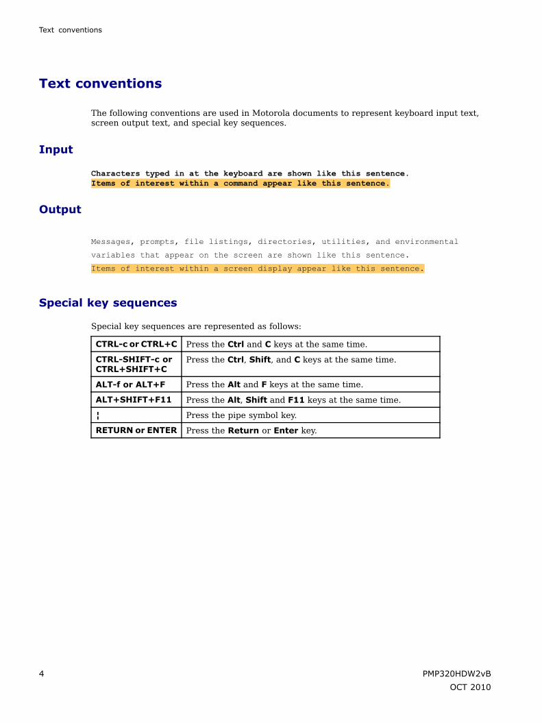
The following conventions are used in Motorola documents to represent keyboard input text,screen output text, and special key sequences.
Input
Characters typed in at the keyboard are shown like this sentence.Items of interest within a command appear like this sentence.
Output
Messages, prompts, file listings, directories, utilities, and environmental
variables that appear on the screen are shown like this sentence.
Items of interest within a screen display appear like this sentence.
Special key sequences
Special key sequences are represented as follows:
CTRL-c or CTRL+C Press the Ctrl and C keys at the same time.
CTRL-SHIFT-c orCTRL+SHIFT+C
Press the Ctrl, Shift, and C keys at the same time.
ALT-f or ALT+F Press the Alt and F keys at the same time.
ALT+SHIFT+F11 Press the Alt, Shift and F11 keys at the same time.
¦ Press the pipe symbol key.
RETURN or ENTER Press the Return or Enter key.
4 PMP320HDW2vB
OCT 2010

Contacting Motorola
Contacting Motorola■ ■ ■ ■ ■ ■ ■ ■ ■ ■ ■ ■ ■ ■ ■ ■ ■ ■ ■ ■ ■ ■ ■ ■ ■ ■ ■ ■ ■ ■ ■ ■ ■ ■ ■ ■ ■ ■ ■ ■ ■ ■ ■ ■ ■ ■ ■ ■ ■ ■ ■ ■ ■ ■ ■ ■ ■ ■ ■ ■ ■
■
■
Motorola appreciates feedback from users about our customer documents. Contact thetechnical support team in your area with any feedback or issues with the documents.
When sending E-mail or calling Motorola for technical support, please include, as appropriate,the software release on each module, the IP addresses, MAC addresses, and features enabledon the system.
Escalate the problem to the PMP 320 Support Team
Escalate any issues to the PMP 320 Support Team by contacting the support team in your area.
U.S. and Canada
E-mail: [email protected]
Telephone: 1–866–961–9288
PMP320HDW2vB 5
OCT 2010

Escalate the problem to the PMP 320 Support Team
Latin and Central America
E-mail: [email protected]
Table 1 Latin and Central America Contact Telephone Numbers
Country Telephone Number
Argentina 0800–666–2789
Brazil 0800–891–4360
Columbia 01–800–912–0557
Mexico 001–800–942–7721
Peru 0800–70–086
All other Latin and Central Americancountries
+420 533 336 946
Europe, Middle East, and Africa
E-mail: [email protected]
Table 2 Europe, Middle East, and Africa Contact Telephone Numbers
Country Telephone Number
Denmark 043682114
France 0157323434
Germany 06950070204
Italy 0291483230
Lithuania 880 030 828
Netherlands 0202061404
Norway 24159815
Portugal 0217616160
Spain 0912754787
Russia 810 800 228 41044
Saudi Arabia 800 844 5345
South Africa 0800981900
United Kingdom 0203 0277499
6 PMP320HDW2vB
OCT 2010

Escalate the problem to the PMP 320 Support Team
Asia and Pacific
E-mail: [email protected]
Table 3 Asia and Pacific Contact Telephone Numbers
Country Telephone Number
Australia 1 800 457 439
China, local DID +86 21 6108 6109
China, northern 10 800 713 0885
China, southern 10 800 130 0867
Hong Kong 30 027 861
India 000 800 100 3098
Indonesia 001 803 015 20 20530
Japan 221626765
Japan, PSTN (81) 335 708 643
Malaysia 1 800 812 384
New Zealand 0 800 448 472
Philippines 63 29 003 057
Singapore 64 155 110
South Korea 080 681 0880
Taiwan 00 801 14 8690
Thailand 001 800 441 0950
All Other Countries
Customer Support: http://motorola.wirelessbroadbandsupport.com/support/technical.php
Telephone: +420 533 336 946
PMP320HDW2vB 7
OCT 2010

Escalate the problem to the PMP 320 Support Team
8 PMP320HDW2vB
OCT 2010

Chapter
1
Product Description■ ■ ■ ■ ■ ■ ■ ■ ■ ■ ■ ■ ■ ■ ■ ■ ■ ■ ■ ■ ■ ■ ■ ■ ■ ■ ■ ■ ■ ■ ■ ■ ■ ■ ■ ■ ■ ■ ■ ■ ■ ■ ■ ■ ■ ■ ■ ■ ■ ■ ■ ■ ■ ■ ■ ■ ■ ■ ■ ■ ■
■
■
■
■
A PMP 320 Access Network provides a low-cost point-to-multipoint broadband solutionoptimized for fixed outdoor applications. The access point is an 802.16e micro base station withWiMAX 802.16e CSM interoperability. The system offers an integrated, all outdoor solutionwith simple installation for rapid deployment.
Target applications for the PMP 320 Access Network include:
• Tier 1, Tier 2, or Tier 3 carriers. Where the PMP 320 system provides a cost-effective,reliable broadband connectivity for residential and business customers.
• Government network operators, where the PMP 320 system provides broadband-basedinfrastructure for administrative networks.
• Wireless service providers, with broadband network service for any size operation.
• Wireline service providers, with broadband wireless extensions for existing DSL or cablenetworks.
As shown in Figure 1-1, a PMP 320 network consists of:
• APs - Cluster Access Point (CAP) 320 Access Points, tower-mounted in a four-sectorconfiguration.
• CPE - Cluster Subscriber Module (CSM) 320, Customer Premise Equipment (CPE), or alsoknown as Subscriber Module (SM) is mounted on a residence or other structure, andpowered by a power adapter providing standard 802.3af power over Ethernet.
• CMM4 (Cluster Management Module 4) – is an outdoor enclosed unit housing a GPSmodule connected to a GPS antenna. It contains synchronization and power-injectioncircuitry, surge protection, and a managed switch. The CMM is used to provide customsynchronization over power over Ethernet to the APs as well as offering a networked,managed switch.
PMP320HDW2vB 1-1
OCT 2010

Escalate the problem to the PMP 320 Support Team Chapter 1: Product Description
Figure 1-1 High Level Network Diagram
High Level Network Diagram
CoreNetwork
Internet
Radio Access Network
AP
DHCP Server(optional)
EMS (optional)(e.g., Wireless Manager)
CPE
AAA Server(optional)
Router(optional)
DNS Server(optional)
CMM4
In addition, a PMP 320 network normally requires:
• AAA Server – Authentication, Authorization, and Accounting server using the RADIUS(Remote Authentication Dial In User Service) protocol
• EMS – an Element Management System, such as the Motorola One Point Wireless Manager
• DHCP Server – Dynamic Host Configuration Protocol server
• DNS Server – Domain Name System server
• CNUT – Network Update Tool for updating device software
• Router – optional
Motorola offers PMP 320 equipment that operates in the spectrum ranges as shown in
Table 1-1 Spectrum Range Operation
Licensed SpectrumRanges
SystemName
APName SM Name AP Model
NumberSM ModelNumber
SupportedFrequencies
3.3 GHz to 3.4 GHz
3.4 GHz to 3.6 GHz
PMP35320
CAP35320
CSM35320
3530APC 3530SM 3.3 GHz to 3.6 GHz
3.6 GHz to 3.8 GHzPMP36320
CAP36320
CSM36320
3630APC 3630SM3.6 GHz to 3.8GHz (Includes3.65 GHz)
1-2 PMP320HDW2vB
OCT 2010

PMP 320 Hardware Installation Access Point (AP)
Access Point (AP)■ ■ ■ ■ ■ ■ ■ ■ ■ ■ ■ ■ ■ ■ ■ ■ ■ ■ ■ ■ ■ ■ ■ ■ ■ ■ ■ ■ ■ ■ ■ ■ ■ ■ ■ ■ ■ ■ ■ ■ ■ ■ ■ ■ ■ ■ ■ ■ ■ ■ ■ ■ ■ ■ ■ ■ ■ ■ ■ ■ ■
■
■
A PMP 320 Access Point (AP) is an 802.16e micro base station that connects wirelessly to up to200 PMP 320 Cluster Subscriber Modules (CSMs) or CPEs (Customer Premise Equipment). TheAP consists of an antenna and radio, as shown in Figure 1-2, with the radio shown separately inFigure 1-3. The standard antenna is a dual-polarity 16.5 dBi antenna typically mounted in a four90 ° sector configuration. The AP is manageable by local web interface, as well as SNMP orthe Motorola One Point Wireless Manager.
WARNINGInstalling an AP involves height, electricity, and exposure to RF (radio frequency)energy. To avoid personal injury, follow applicable national and local safety regulationsalong with industry best practices. Also follow the specific guidelines in this document,including maintaining a sustained exposure separation distance of 50 cm (~20 inches)as described in the Regulatory, Legal, and Safety Notice in this document.
Figure 1-2 Access Point (AP) shown with the antenna attached and mounted on pole
Radio attached to Antenna with
Appropriate Hardware
Rotate Up To vertical poistion.
PMP320HDW2vB 1-3
OCT 2010

Access Point (AP) Chapter 1: Product Description
Figure 1-3 AP, radio only
The PMP 320 AP uses 802.16e for the over-the-air connection to the SMs or CSM. It is 802.16ePHY and MAC compliant, and complies with the WiMAX Wave2 profile, except for mobility.
The AP uses a custom 56 VDC power system, typically powered by a CMM4. The AP usesless than 25 W per AP, or less than 100 watts for 360 ° coverage. The AP includes integratedsurge suppression that is the equivalent to the 600SSD surge suppressor recommended for theCSM (Cluster Subscriber Module) installations.
The AP functions as a router in the network, with routes to the CSMs (or SMs) auto-configured.The AP supports ICMP and ARP.
The AP:
• can be configured to either receive its IP address from a network DHCP server, or bemanually assigned its IP address.
• can be configured to respond to SM DHCP requests either by relaying the requests to anetwork DHCP server, or function as a DHCP server itself.
• can be configured either to use an external AAA (Authentication, Authorization, andAccounting) server, or use a minimal internal AAA server. When configured to use anexternal AAA server, the AP serves as a relay between CSMs (SMs) and the AAA serverfor authentication requests, and serves as a RADIUS client communicating with the AAAserver for authorization of SM services.
• has an embedded web server for configuring using a web browser.
• supports SNMP v1, and uses standard 802.16e MIBs (Management Information Base) aswell as the Motorola 802.16e AP MIB. The AP supports all Object Identifiers (OIDs) withSNMP v1 and SNMP v2, however all traps are SNMP v1.
1-4 PMP320HDW2vB
OCT 2010
PMP 320 Hardware Installation Site preparation
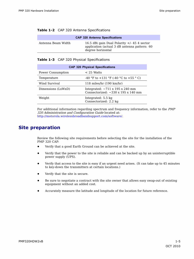
Table 1-2 CAP 320 Antenna Specifications
CAP 320 Antenna Specifications
Antenna Beam Width 16.5 dBi gain Dual Polarity +/- 45 4 sectorapplication (actual 3 dB antenna pattern: 60degree horizontal
Table 1-3 CAP 320 Physical Specifications
CAP 320 Physical Specifications
Power Consumption < 25 Watts
Temperature -40 °F to +131 °F (-40 °C to +55 ° C)
Wind Survival 118 miles/hr (190 km/hr)
Dimensions (LxWxD) Integrated: ~711 x 195 x 240 mmConnectorized: ~330 x 195 x 140 mm
Weight Integrated: 5.5 kgConnectorized: 2.2 kg
For additional information regarding spectrum and frequency information, refer to the PMP320 Administration and Configuration Guide located at:http://motorola.wirelessbroadbandsupport.com/software/.
Site preparation
Review the following site requirements before selecting the site for the installation of thePMP 320 CAP:
• Verify that a good Earth Ground can be achieved at the site.
• Verify that the power to the site is reliable and can be backed up by an uninterruptiblepower supply (UPS).
• Verify that access to the site is easy if an urgent need arises. (It can take up to 45 minutesto key-down the transmitters at certain locations.)
• Verify that the site is secure.
• Be sure to negotiate a contract with the site owner that allows easy swap-out of existingequipment without an added cost.
• Accurately measure the latitude and longitude of the location for future reference.
PMP320HDW2vB 1-5
OCT 2010

Cluster Management Module 4 (CMM4) Chapter 1: Product Description
Cluster Management Module 4 (CMM4)■ ■ ■ ■ ■ ■ ■ ■ ■ ■ ■ ■ ■ ■ ■ ■ ■ ■ ■ ■ ■ ■ ■ ■ ■ ■ ■ ■ ■ ■ ■ ■ ■ ■ ■ ■ ■ ■ ■ ■ ■ ■ ■ ■ ■ ■ ■ ■ ■ ■ ■ ■ ■ ■ ■ ■ ■ ■ ■ ■ ■
■
■
The Cluster Management Module 4 (CMM4) provides power, synchronization, and networkconnectivity for up to eight APs, backhauls, and Ethernet terrestrial feeds in variousconfigurations.
Figure 1-4 CMM4 with door open
Cabling Diagram on Inside of Front Door
The CMM4 provides:
• Sync over Power over Ethernet and integrated surge suppression on the controller boardfor up to 8 APs or BHs. Both a custom 30 VDC power scheme and a custom 56 VDC powerscheme are available. Neither is the same as the later IEEE Standard 802.3af, and neitheris compatible with it.
• Managed switching using a hardened EtherWAN switch. The CMM4 ships with a 14-portEtherWAN switch and is also available without a switch.
• A weather-tight enclosure with either 4 or 7 glands/ports for Ethernet and power cables.
• Surge suppression on the controller board for the incoming 30 V DC and 56 V DC powerlines and GPS coax cable.
1-6 PMP320HDW2vB
OCT 2010

PMP 320 Hardware Installation Cluster Management Module 4 (CMM4)
• Auto-negotiation on the Ethernet ports. Ports will auto-negotiate to match inputs that areeither 100Base-T or 10Base-T, and either full duplex or half duplex, when the connecteddevice is set to auto-negotiate. Alternatively, these parameters are settable.
• An always-on NTP (Network Time Protocol) server that can provide the date and time toany radio that can reach the management IP address of the CMM.
Table 1-4 CMM4 Model Numbers and Ethernet Switch Configurations
EtherWAN SwitchCMM4 Model
NumberCMM4 ExtendedModel Number Total Ports 10/100 Base
–TX Ports10/100/1000
Base-TX PortsCable Glands (ports)
1090CKBA (currentunits)
14 12 2 7
1090CK1090CKAA (earlierunits)
9 8 1 4
1091 NA No Switch 7
Inside the CMM4 enclosure is a controller board, an EtherWAN switch, and a GPS coaxsurge suppressor. Also inside the CMM4 enclosure is the EtherWAN switch port. Thisconnection is where the Ethernet Gigabit connection is made. For more information aboutthe EtherWAN switch and how the port is managed or for information on earlier versionsof the CMM4 units refer to the Cluster Management Module 4 User Guide located at:http://motorola.wirelessbroadbandsupport.com/software/.
The controller board injects power and synchronization on up to eight Ethernet ports andprovides the equivalent of 600SSD surge suppression on each of the eight ports. The controllerboard is managed using a web browser, or SNMP, and is supported by the Prizm ElementManagement System (EMS). The controller board receives 30 VDC power and/or 56 VDC fromexternal power supplies, and provides 20 VDC power for the EtherWAN switch and otherauxiliary equipment. The controller board includes a GPS module, which provides sync andGPS information to the CMM, a management port, an override toggle switch, and an auxiliarysync port for connecting to another CMM.
NOTEThe controller board does not convert 30 VDC to 56 VDC or 56 VDC to 30 VDC. Topower 56 VDC equipment from a CMM4 you must provide a 56 VDC power supply, andto power 30 VDC equipment from a CMM4 you must provide a 30 VDC power supply.
The CMM4 requires a GPS antenna and a power supply. The directions for installing the powersupply and the GPS are provided in Chapter 3 CMM4 Hardware Installation.
PMP320HDW2vB 1-7
OCT 2010

What is included when the CMM4 unit is shipped Chapter 1: Product Description
What is included when the CMM4 unit is shipped
The CMM4 as shipped includes:
• Weatherized enclosure containing the controller board, EtherWAN Ethernet Switch, andGPS coax surge suppressor
• Patch cables between the controller board and the EtherWAN Ethernet Switch
• U-bolts and V-brackets for pole-mounting the CMM4
• GPS Antenna
• GPS antenna pole-mount kit
• A 1-hole cable gland insert for use on the DC power cable
The CMM4 as shipped does not include:
• Any power supply. The appropriate power supply(s), 30 VDC and/or 56 VDC, must beordered separately
• Ethernet cables to connect the CMM4 to APs, backhauls, or terrestrial feeds
• Coaxial cable connecting the CMM4 to the GPS antenna
• DC power line cables are not provided (AC power line cables are not included with thepower supplies)
1-8 PMP320HDW2vB
OCT 2010

PMP 320 Hardware Installation Point to Multi-point Integrated Cluster Subscriber Module 320
Point to Multi-point Integrated Cluster SubscriberModule 320
■ ■ ■ ■ ■ ■ ■ ■ ■ ■ ■ ■ ■ ■ ■ ■ ■ ■ ■ ■ ■ ■ ■ ■ ■ ■ ■ ■ ■ ■ ■ ■ ■ ■ ■ ■ ■ ■ ■ ■ ■ ■ ■ ■ ■ ■ ■ ■ ■ ■ ■ ■ ■ ■ ■ ■ ■ ■ ■ ■ ■
■
■
In this document, the PMP 320 CSM with the integrated antenna is referred to as the IntegratedCSM. This nomenclature helps to distinguish any differences between the Integrated CSM andthe Connectorized CSM. The Connectorized CSM is introduced in the following section.
Figure 1-5 Integrated CSM 320 Subscriber Module
Canopy CSM 320
Front RearEthernet Connector
The Integrated PMP 320 Cluster Subscriber Module (CSM) or also known as the CustomerPremise Equipment (CPE), or the Subscriber Module (SM) is the device that extends thebroadband network or internet services to the end user through communication with the PMP320 AP. The key features of the CSM are:
• an integrated 14.5 dBi gain antenna
• 802.3af power over Ethernet (48 VDC)
• 802.16e standard fixed, outdoor solution
• products that are available in the 3.3 GHz – 3.8 GHz spectrum
The Integrated CSM is managed by a local web interface, SNMP, or the Motorola WirelessManager. The CSM also functions as a Network Address Translation (NAT) device.
PMP320HDW2vB 1-9
OCT 2010
Site considerations Chapter 1: Product Description
Site considerations
Review the following site requirements before selecting the site for the installation of thePMP 320 Integrated CSM:
• When ordering Integrated CSMs for the site, ensure that the same band CSM is ordered asis used for the AP.
• Mount the Integrated CSM as high off the ground as possible to minimize theft.
• Communicate to the end user that they are responsible for the loss/damage to the CSMwhile in their care.
• Route and hide the ENET cables against the house following local installation codes.This extra effort lowers the chance of a new home owner taking down the IntegratedCSM and its wiring.
• Avoid penetrating the roof; helping to mitigate issues with leaks.
• Work with the local home owners association (HOA) to receive approval of the IntegratedCSM solution.
• Take several measurements to several different AP locations, the closest AP might notbe the best signal.
• Perform an RF survey of the surrounding area; chances are that this installation ignitesmore interest in this solution in the area.
1-10 PMP320HDW2vB
OCT 2010

PMP 320 Hardware Installation Point to Multi-point Connectorized Cluster Subscriber Module 320
Point to Multi-point Connectorized Cluster SubscriberModule 320
■ ■ ■ ■ ■ ■ ■ ■ ■ ■ ■ ■ ■ ■ ■ ■ ■ ■ ■ ■ ■ ■ ■ ■ ■ ■ ■ ■ ■ ■ ■ ■ ■ ■ ■ ■ ■ ■ ■ ■ ■ ■ ■ ■ ■ ■ ■ ■ ■ ■ ■ ■ ■ ■ ■ ■ ■ ■ ■ ■ ■
■
■
Figure 1-6 Connectorized CSM 320 subscriber module
Canopy CSM 320
FRONT REAR REARShowing HeatsinkHeatsink Not Shown
(Ethernet Connector)
Ethernet Connector
(2X N-type Connector)2X N-type
Connector
Figure 1-7 Connectorized CSM 320 rear view subscriber module
G1_ccsm_ant_connid.eps
MAIN
Ethernet
BOTTOM VIEW
N-Type Antenna ConnectorsGround
PMP320HDW2vB 1-11
OCT 2010

Site considerations Chapter 1: Product Description
The PMP 320 Connectorized Cluster Subscriber Module (CSM) or also known as the CustomerPremise Equipment (CPE), or the Subscriber Module (SM) is the device that extends thebroadband network or internet services to the end user through communication with the PMP320 AP. The key features of the CSM are:
• 802.3af power over Ethernet (48 VDC)
• 802.16e standard fixed, outdoor solution
• products that are available in the 3.3 GHz – 3.8 GHz spectrum
The Connectorized CSM is managed by a local web interface, SNMP, or the Motorola WirelessManager. The Connectorized CSM also functions as a Network Address Translation (NAT)device. In layer 2 convergence, the CSM may also be configured as a bridge.
Site considerations
Review the following site requirements before selecting the site for the installation of thePMP 320 CSM:
• When ordering Connectorized CSMs for the site, ensure that the same band ConnectorizedCSM is ordered as is used for the AP.
• Mount the Connectorized CSM as high off the ground as possible to minimize theft.
• Communicate to the end user that they are responsible for the loss/damage to theConnectorized CSM while in their care.
• Route and hide the ENET cables against the house following local installation codes.This extra effort lowers the chance of a new home owner taking down the ConnectorizedCSM and its wiring.
• Avoid penetrating the roof; this helps mitigate issues with leaks.
• Work with the local home owners association (HOA) to receive approval of theConnectorized CSM solution.
• Take several measurements to several different AP locations, the closest AP might notbe the best signal.
• Perform an RF survey of the surrounding area; chances are that this installation ignitesmore interest in this solution in the area.
1-12 PMP320HDW2vB
OCT 2010

Chapter
2
AP Hardware Installation■ ■ ■ ■ ■ ■ ■ ■ ■ ■ ■ ■ ■ ■ ■ ■ ■ ■ ■ ■ ■ ■ ■ ■ ■ ■ ■ ■ ■ ■ ■ ■ ■ ■ ■ ■ ■ ■ ■ ■ ■ ■ ■ ■ ■ ■ ■ ■ ■ ■ ■ ■ ■ ■ ■ ■ ■ ■ ■ ■ ■
■
■
■
■
This chapter provides the instructions and procedures needed to:
• connect the antenna brackets
• connect the AP radio antenna to the antenna
• cable the unit
• mount the unit to a pole, mounting fixture, or tower
• ground the unit
• connect surge suppression
PMP320HDW2vB 2-1
OCT 2010
Installing the AP Hardware Chapter 2: AP Hardware Installation
Installing the AP Hardware■ ■ ■ ■ ■ ■ ■ ■ ■ ■ ■ ■ ■ ■ ■ ■ ■ ■ ■ ■ ■ ■ ■ ■ ■ ■ ■ ■ ■ ■ ■ ■ ■ ■ ■ ■ ■ ■ ■ ■ ■ ■ ■ ■ ■ ■ ■ ■ ■ ■ ■ ■ ■ ■ ■ ■ ■ ■ ■ ■ ■
■
■
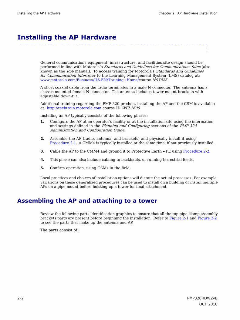
General communications equipment, infrastructure, and facilities site design should beperformed in line with Motorola’s Standards and Guidelines for Communications Sites (alsoknown as the R56 manual). To access training for Motorola's Standards and Guidelinesfor Communication Sitesrefer to the Learning Management System (LMS) catalog at:www.motorola.com/Business/US-EN/Training+Home/course NST925.
A short coaxial cable from the radio terminates in a male N connector. The antenna has achassis-mounted female N connector. The antenna includes tower mount brackets withadjustable down-tilt.
Additional training regarding the PMP 320 product, installing the AP and the CSM is availableat: http://techtrain.motorola.com course ID WEL1605
Installing an AP typically consists of the following phases:
1. Configure the AP at an operator's facility or at the installation site using the informationand settings defined in the Planning and Configuring sections of the PMP 320Administration and Configuration Guide.
2. Assemble the AP (radio, antenna, and brackets) and physically install it usingProcedure 2-1. A CMM4 is typically installed at the same time, if not previously installed.
3. Cable the AP to the CMM4 and ground it to Protective Earth – PE using Procedure 2-2.
4. This phase can also include cabling to backhauls, or running terrestrial feeds.
5. Confirm operation, using CSMs in the field.
Local practices and choices of installation options will dictate the actual processes. For example,variations on these generalized procedures can be used to install on a building or install multipleAPs on a pipe mount before hoisting up a tower for final attachment.
Assembling the AP and attaching to a tower
Review the following parts identification graphics to ensure that all the top pipe clamp assemblybrackets parts are present before beginning the installation. Refer to Figure 2-1 and Figure 2-2to see the parts that make up the antenna and AP.
The parts consist of:
2-2 PMP320HDW2vB
OCT 2010

PMP 320 Hardware Installation Assembling the AP and attaching to a tower
Table 2-1 Part list for the antenna and AP
Part name Quantity
Antenna 1
AP radio 1
Attaching brackets to antenna
Scissors bracket 1
Top pipe clamp assembly 1
Bottom pipe clamp assembly 1
2.24 inch spacer 2
2.36 inch spacer 1
5/16-18 x 3.5 inch hex pivotbolt
3
5/16-18 inch split lockwasher
3
5/16-18 flat washer 3
5/16-18 hex nut 3
Attaching AP to Antenna
M6 carriage bolt 2
M6 split lock washer 2
M6 flat washer 2
M6 hex nut 2
Attaching pipe clamps to pipe
3/8-16 inch split lock washer 4
3/8-16 inch flat washer 4
3/8-16 hex nut 4
PMP320HDW2vB 2-3
OCT 2010

Assembling the AP and attaching to a tower Chapter 2: AP Hardware Installation
Figure 2-1 Pipe Clamp Assembly Identification
3/8-16Hex Nut
3/8-16Split Lock Washer
3/8-16Lock Washer
3/8-16Hex Nut
3/8-16Split Lock Washer
3/8-16Lock Washer
Longer Bracket
TOP PIPE CLAMP ASSEMBLY
BOTTOM PIPE CLAMP ASSEMBLY
Figure 2-2 AP and antenna parts with scissors bracket
Antenna
DIV connector
MAIN connector
Ethernet
Pole Is Shown For Reference
Radio(Secured on Antenna)
2-4 PMP320HDW2vB
OCT 2010

PMP 320 Hardware Installation Assembling the AP and connecting the antenna
Assembling the AP and connecting the antenna
Use the following procedure to assemble the pipe clamp brackets to the AP, and attach the radioto the antenna. These steps are performed before the AP is mounted on the pole.
Required Tools
• Two ½ inch wrenches
• 9/16 inch wrench and inclinometer
• 10mm socket wrench
Torque Requirements
• 3/8 -16 pipe clamp hardware to 9 ft-lbs (12.2 N.m)
• 5/16-18 mount hardware 10 ft-lbs (13.5 N.m)
• M6 hardware 7 ft-lbs (9.5 N.m)
Procedure 2-1 Assemble the AP and antenna for pole mounting
Continued
PMP320HDW2vB 2-5
OCT 2010

Assembling the AP and connecting the antenna Chapter 2: AP Hardware Installation
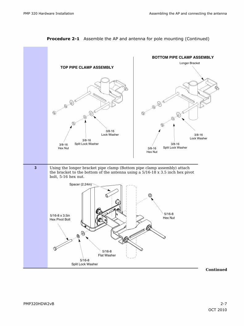
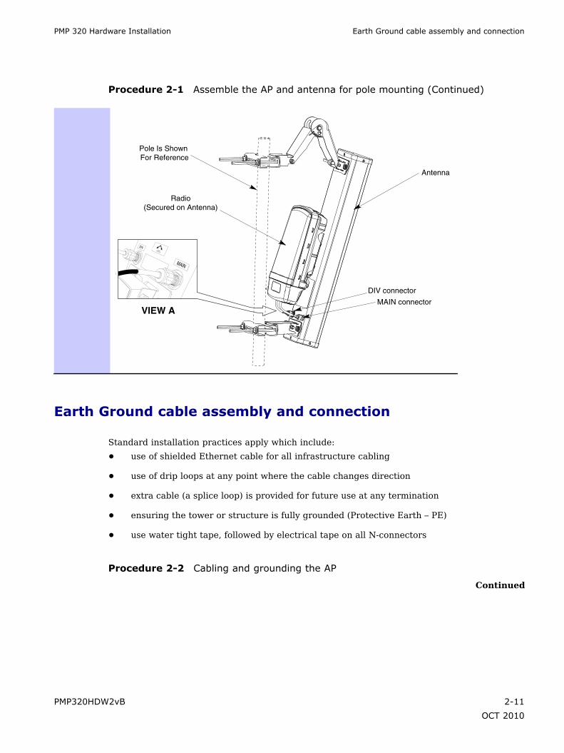
Procedure 2-1 Assemble the AP and antenna for pole mounting (Continued)
1 Perform a parts check to ensure all parts are present.
DIV MAIN
2 Connect the pipe clamp assembly brackets to the antenna.
NOTEDetermine between the two pipe clamp assemblies which brackethas the longer bracket bar. The bracket with the longer bar isattached to the bottom of the antenna. The bracket with the shorterbar is used for the top of the antenna and connected to the scissorsdowntilt bracket.
Continued
2-6 PMP320HDW2vB
OCT 2010
PMP 320 Hardware Installation Assembling the AP and connecting the antenna
Procedure 2-1 Assemble the AP and antenna for pole mounting (Continued)
3/8-16Hex Nut
3/8-16Split Lock Washer
3/8-16Lock Washer
3/8-16Hex Nut
3/8-16Split Lock Washer
3/8-16Lock Washer
Longer Bracket
TOP PIPE CLAMP ASSEMBLY
BOTTOM PIPE CLAMP ASSEMBLY
3 Using the longer bracket pipe clamp (Bottom pipe clamp assembly) attachthe bracket to the bottom of the antenna using a 5/16-18 x 3.5 inch hex pivotbolt, 5-16 hex nut.
5/16-8Hex Nut
5/16-8Split Lock Washer
5/16-8Flat Washer
Spacer (2.24in)
5/16-8 x 3.5inHex Pivot Bolt
Continued
PMP320HDW2vB 2-7
OCT 2010

Assembling the AP and connecting the antenna Chapter 2: AP Hardware Installation
Procedure 2-1 Assemble the AP and antenna for pole mounting (Continued)
4 Using a 5/16-18 x 3.5 hex pivot bolt, 5-16 split lock waster, 5/16 split flatwasher, smaller spacer (2.36 inches) and a 5/16 hex nut, connect the scissorbracket to the top of the antenna.
Outside
See Detail A
Detail A
Inverted Scissor Mount
Spacer (2.36in)
5/16-8Hex Nut
5/16-8 x 3.5inHex Pivot Bolt
5/16-8Flat Washer
5/16-8Split Lock Washer
5 Using the bracket with the shorter bar, attach the downtilt scissor bracketpointing up (inverted scissor mount) to avoid physical interference betweenthe bracket and the radio housing. Connect the scissor bracket to the shortpipe bracket to the scissor bracket by attaching the 5/16-18 x 3.5 inch hexpivot bolt, 5/16-18 flat washer, shorter spacer (2.24 inches) and the 5/16 –18 hex nut.
Continued
2-8 PMP320HDW2vB
OCT 2010

PMP 320 Hardware Installation Assembling the AP and connecting the antenna
Procedure 2-1 Assemble the AP and antenna for pole mounting (Continued)
5/16-8Hex Nut
5/16-8Split Lock Washer
5/16-8Flat WasherUse Shorter
Spacer (2.24in)
5/16-8 x 3.5inHex Pivot Bolt
See Detail A
Detail A
NOTEUse a level (inclinometer) to tilt of the antenna when installing atthe site. The scissor bracket has degree markings from 0 to 15 onthe bracket, but it is recommended for accuracy to use a level.
6 Connect the radio to the antenna by sliding it into the captive space.
2X M6 Hex Nut2X M6 Lock Washer2X M6 Flat Washer
2X M6 Carriage Bolt
Antenna
Radio
NOTE: Slide Radio into captive space of Antenna First then secure with mounting hardware
Continued
PMP320HDW2vB 2-9
OCT 2010

Assembling the AP and connecting the antenna Chapter 2: AP Hardware Installation
Procedure 2-1 Assemble the AP and antenna for pole mounting (Continued)
7 Secure the radio to the antenna using the two M6 carriage bolts, M6 flatwashers; M6 split lock washer and the M6 hex nut. Torque the M6 nut 7 ft-lbs(9.5 N.m).
The unit is shown away from the antenna in order to illustrate bolt locations.
M6 Hex NutM6 Lock WasherM6 Flat Washer
M6 Carriage Bolt
Antenna
DIV Connector
MAIN Connector
Radio
Pole Is Shown For Reference
M6 Hex NutM6 Lock WasherM6 Flat Washer
M6 Carriage Bolt
8 Connect the cable labeled:
• MAIN to the antenna connector labeled MAIN
• with no label to the antenna connector labeled DIV (Diversity).
Continued
2-10 PMP320HDW2vB
OCT 2010
PMP 320 Hardware Installation Earth Ground cable assembly and connection
Procedure 2-1 Assemble the AP and antenna for pole mounting (Continued)
Antenna
DIV connector
MAIN connector
Pole Is Shown For Reference
Radio(Secured on Antenna)
VIEW A
DIVANTENNAPOLARIZATION
MAIN
Earth Ground cable assembly and connection
Standard installation practices apply which include:
• use of shielded Ethernet cable for all infrastructure cabling
• use of drip loops at any point where the cable changes direction
• extra cable (a splice loop) is provided for future use at any termination
• ensuring the tower or structure is fully grounded (Protective Earth – PE)
• use water tight tape, followed by electrical tape on all N-connectors
Procedure 2-2 Cabling and grounding the AP
Continued
PMP320HDW2vB 2-11
OCT 2010

Earth Ground cable assembly and connection Chapter 2: AP Hardware Installation
Procedure 2-2 Cabling and grounding the AP (Continued)
1 Remove the connection protection casing using the thumb release at theback of the AP Unit.
2 Use dielectric grease (which is uniformly non-conducting) on all connectionsand in all RJ-45 Ethernet connectors. The best practice is to use enoughgrease to fill the RJ- 45 female connector, and then insert the RJ-45 maleconnector and push the grease further into the unit and around the RJ-45connector. Excess grease can be wiped over the connector area to providesome resistance to water ingress around the connector.
Connect the Ethernet cable to the connector labeled ETHERNET. Note thatthe AUX port is not used at this time.
Continued
2-12 PMP320HDW2vB
OCT 2010

PMP 320 Hardware Installation Earth Ground cable assembly and connection
Procedure 2-2 Cabling and grounding the AP (Continued)
AUX.ETHERNET
24 to 59V 22W
Class 2 or LPSCAUTION
LNK/5
ACT/4
GPS/3PWR
SYN/1
SES/2
This device complies with Part 15 of the FCC Rules.
Operation is subject to the following two conditions.
3 Run a 10 AWG ground strap from the ground lug on the AP to known goodground (Protective Earth - PE).
AP Ground Lug
Ground the radio to the tower.
4 Be sure to reattach the bottom cover of the AP connection cover.
PMP320HDW2vB 2-13
OCT 2010

LED indicator Chapter 2: AP Hardware Installation
LED indicator
The LED display for the AP are either Green or off.
Figure 2-3 LED location diagram
AUX.ETHERNET
24 to 59V 22W
Class 2 or LPSCAUTION
LNK/5
ACT/4
GPS/3PWR
SYN/1
SES/2
This device complies with Part 15 of the FCC Rules.
Operation is subject to the following two conditions.
Table 2-2 LED indicators for the AP
LED Description
PWR (D14) Power – green indicates the DC poweris on. This LED indicates that the
board is powered on.
SYN/1 (D13) Synchronization indicator – this indicator ison whenever the AP is synchronized with theGPS, or when ever the GPS is not used at all.
SES/2 (D12) Not used, but is always ON.
LNK/5 (D9) GMAC Ethernet – the LED is on whenthe GMAC Ethernet link is up.
ACT/4 (D10) Activity – indicates activity on the ENET port.
GPS/3 (D11) GPS pulse indicator – this LED is onevery 1 pps interrupt, and turned off 20
frames after 100 milliseconds).
2-14 PMP320HDW2vB
OCT 2010
PMP 320 Hardware Installation Attach the AP assembly to a pole
Attach the AP assembly to a pole
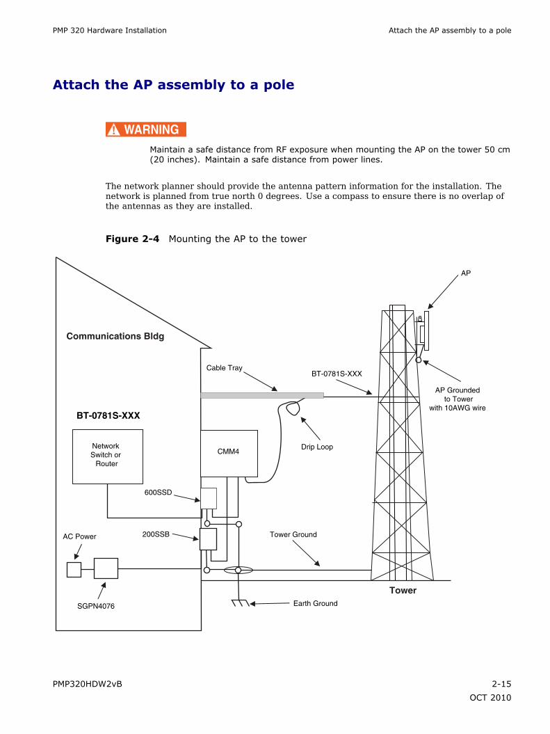
WARNINGMaintain a safe distance from RF exposure when mounting the AP on the tower 50 cm(20 inches). Maintain a safe distance from power lines.
The network planner should provide the antenna pattern information for the installation. Thenetwork is planned from true north 0 degrees. Use a compass to ensure there is no overlap ofthe antennas as they are installed.
Figure 2-4 Mounting the AP to the tower
Tower
BT-0781S-XXX
Earth Ground
Communications Bldg
600SSD
AP Grounded to Tower
with 10AWG wire
BT-0781S-XXX
AC Power
SGPN4076
Cable Tray
Tower Ground
Drip Loop
AP
Network Switch or
Router
200SSB
CMM4
PMP320HDW2vB 2-15
OCT 2010

Attach the AP assembly to a pole Chapter 2: AP Hardware Installation
NOTE
• The L-COM surge suppressor is used if the Gigabit Ethernet port is used inthe CMM4. The L-COM when used is installed either in the CMM4 cabinet, orinstalled inside the communications building.
• This figure shows the GPS near the top of the AP unit. For installationinformation about the GPS refer to Installing the GPS Antenna on page 3-7.
• The AC line cord is not provided with the hardware.
This figure shows the GPS near the top of the AP unit. For installation information about theGPS refer to Installing the GPS Antenna on page 3-7.
Procedure 2-3 Attaching the AP assembly to a pole
1 Using standard work and safety practices for tower climbing, connect theassembled unit (assembled antenna, brackets and radio) to a pole, mountingfixture, or a tower. The unit must be mounted to avoid accidental touchingby personnel. The standard mounting height is typically at least 4 m (13ft) above ground level.
Antenna
DIV connector
MAIN connector
Ethernet
Pole Is Shown For Reference
Radio(Secured on Antenna)
NOTEApproximate cable distance between the AP and the CMM4 is 100meters.
Continued
2-16 PMP320HDW2vB
OCT 2010

PMP 320 Hardware Installation Attach the AP assembly to a pole
Procedure 2-3 Attaching the AP assembly to a pole (Continued)
2 Install the top and bottom clamps to the pipe. Slide the clamp bracket on tothe carriage bolts. Slide on a 3/8-16 flat washer, 3/8-16 split lock washer anda 3/8-16 hex nut to each carriage bolt.
NOTE
• Align the AP setting the desired downtilt degree using theinclinometer.
• The network planner should provide the antenna patterninformation for the installation. The network is planned fromtrue north 0 degrees. Use a compass to ensure there is nooverlap of the antennas as they are installed.
Tighten the hex nut to 10 ft-lbs (13.5 N.m) after the AP has been aligned tothe optimum downtilt position.
3 Connect the Ethernet cable from the AP to the CMM4 port controller. Thereare up to 14 ports in one CMM4 switch, but only 8 ports on the CMM4motherboard that can power up a radio. Ensure that surge suppression hasbeen installed for this connection. See the section on Surge SuppressionInformation. Follow the site plan created by the network planner whenconnecting cables to the CMM4 switch.
Continued
PMP320HDW2vB 2-17
OCT 2010
Attach the AP assembly to a pole Chapter 2: AP Hardware Installation
Procedure 2-3 Attaching the AP assembly to a pole (Continued)
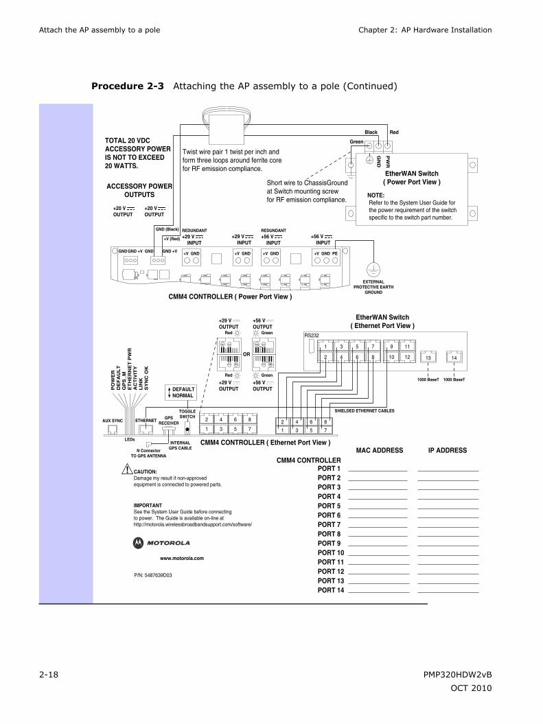
GND (Black)
+V (Red)
NOTE: Refer to the System User Guide for the power requirement of the switch specific to the switch part number.
TOTAL 20 VDCACCESSORY POWERIS NOT TO EXCEED20 WATTS.
CMM4 CONTROLLER ( Ethernet Port View )
CMM4 CONTROLLER ( Power Port View )
EtherWAN Switch( Ethernet Port View )
EtherWAN Switch( Power Port View )
ACCESSORY POWEROUTPUTS
PO
WE
RD
EF
AU
LT
GP
S_
ME
TH
ER
NE
T P
WR
AC
TIV
ITY
LIN
KS
YN
C O
K
REDUNDANT+29 V INPUT
REDUNDANT+56 V INPUT
GN
D
PW
R
Black Red
Green
+29 VOUTPUT
+29 V INPUT
+56 V INPUT
+20 VOUTPUT
+20 VOUTPUT
+29 VOUTPUT
+56 VOUTPUT
+56 VOUTPUT
OR
DEFAULTNORMAL
AUX SYNC ETHERNET
LEDs
N ConnectorTO GPS ANTENNA
INTERNALGPS CABLE
GND GND +V GND GND +V +V GND +V GND +V GND PE+V GND
GPSRECEIVER
TOGGLESWITCH
Red
Red
Green
EXTERNALPROTECTIVE EARTH
GROUND
SHIELDED ETHERNET CABLES
1000 BaseT 1000 BaseTGreen
2
1
4
3
6
5
8
7
8
7
6
5
4
3
2
1
7
8
5
6
3
4
1
2
11
12
9
10 13 14
RS232
Twist wire pair 1 twist per inch andform three loops around ferrite corefor RF emission compliance.
Short wire to ChassisGroundat Switch mounting screwfor RF emission compliance.
CMM4 CONTROLLER
CAUTION:Damage my result if non-approvedequipment is connected to powered parts.
IMPORTANTSee the System User Guide before connectingto power. The Guide is available on-line athttp://motorola.wirelessbroadbandsupport.com/software/
www.motorola.com
P/N: 5487639D03
MAC ADDRESS IP ADDRESS
PORT 1PORT 2PORT 3PORT 4PORT 5PORT 6PORT 7PORT 8PORT 9PORT 10PORT 11PORT 12PORT 13PORT 14
2-18 PMP320HDW2vB
OCT 2010
PMP 320 Hardware Installation Surge Suppression Information
Surge Suppression Information
The AP has metal-to-metal contact from the tower or support structure, through the antenna,through the coax cable, to the radio. Installing surge suppression at the AP is stronglyrecommended to provide the best protection from lightning strikes.
Up to four 600SSD surge suppressors can be mounted in series on an Ethernet link withoutdegrading the link. The equivalent of a 600SSD is built into each of the 8 ports on a CMM4 andcounts as one of the four.
As an example, a typical installation might have properly-grounded 600SSD units within 3 ft (1m) of each AP and additional properly-grounded 600SSD units on each Ethernet cable mountedoutside at the point of cable entry to a telecommunications hut that contains the CMM4.
AP Hardware Installation complete
The AP hardware installation is complete. Refer to the PMP 320 Administration andConfiguration Guide to update software or configure the device.
PMP320HDW2vB 2-19
OCT 2010

AP Hardware Installation complete Chapter 2: AP Hardware Installation
2-20 PMP320HDW2vB
OCT 2010

Chapter
3
CMM4 Hardware Installation■ ■ ■ ■ ■ ■ ■ ■ ■ ■ ■ ■ ■ ■ ■ ■ ■ ■ ■ ■ ■ ■ ■ ■ ■ ■ ■ ■ ■ ■ ■ ■ ■ ■ ■ ■ ■ ■ ■ ■ ■ ■ ■ ■ ■ ■ ■ ■ ■ ■ ■ ■ ■ ■ ■ ■ ■ ■ ■ ■ ■
■
■
■
■
The CMM4 consists of three subsystems:
• the CMM4 enclosure and controller board
• power supplies
• an EtherWAN switch (mounted in the CMM4 enclosure).
PMP320HDW2vB 3-1
OCT 2010
AP Hardware Installation complete Chapter 3: CMM4 Hardware Installation
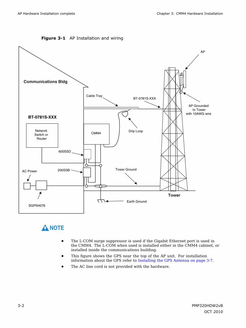
Figure 3-1 AP Installation and wiring
Tower
BT-0781S-XXX
Earth Ground
Communications Bldg
600SSD
AP Grounded to Tower
with 10AWG wire
BT-0781S-XXX
AC Power
SGPN4076
Cable Tray
Tower Ground
Drip Loop
AP
Network Switch or
Router
200SSB
CMM4
NOTE
• The L-COM surge suppressor is used if the Gigabit Ethernet port is used inthe CMM4. The L-COM when used is installed either in the CMM4 cabinet, orinstalled inside the communications building.
• This figure shows the GPS near the top of the AP unit. For installationinformation about the GPS refer to Installing the GPS Antenna on page 3-7.
• The AC line cord is not provided with the hardware.
3-2 PMP320HDW2vB
OCT 2010

PMP 320 Hardware Installation Before you begin
Before you begin■ ■ ■ ■ ■ ■ ■ ■ ■ ■ ■ ■ ■ ■ ■ ■ ■ ■ ■ ■ ■ ■ ■ ■ ■ ■ ■ ■ ■ ■ ■ ■ ■ ■ ■ ■ ■ ■ ■ ■ ■ ■ ■ ■ ■ ■ ■ ■ ■ ■ ■ ■ ■ ■ ■ ■ ■ ■ ■ ■ ■
■
■
Ensure that you comply with standard local or national electrical and climbing procedureswhen you install the CMM4.
WARNINGInstalling a CMM involves electrical power and can involve height and exposure toRF (Radio Frequency) energy. To avoid personal injury, know and follow applicablenational and local safety regulations and industry best practices, and follow thespecific guidelines in this document
If the CMM4 is being installed on a tower instead of a communications hut, the operator willhave to calculate the wind loading on the tower for the addition of the CMM4.
Avoiding Hazards
Use simple precautions to protect staff and equipment. Hazards include exposure to RF waves,lightning strikes, and power surges. This section specifically recommends actions to abatethese hazards.
Grounding Equipment
Effective lightning protection diverts lightning current safely to ground, Protective Earth (PE).It neither attracts nor prevents lightning strikes.
PMP320HDW2vB 3-3
OCT 2010

Grounding Infrastructure Equipment Chapter 3: CMM4 Hardware Installation
Grounding Infrastructure Equipment
To protect both your staff and your infrastructure equipment, implement lightning protectionas follows:
• Observe all local and national codes that apply to grounding for lightning protection.
• Before you install your modules, perform the following steps:
Engage a grounding professional if you have any questions on grounding.
Install lightning arrestors to transport lightning strikes away from equipment. Forexample, install a lightning rod on a tower leg other than the leg to which you mountyour module.
Connect your lightning rod to ground.
Plan to use an appropriate surge suppressor on any Ethernet cable at the point whereit enters any building or structure.
• Install your modules at least 2 feet (0.6 meters) below the tallest point on the tower, pole,or roof.
Conforming to Regulations
For all electrical purposes, ensure that your network conforms to applicable country and localcodes, such as the NEC (National Electrical Code) in the U.S.A. If you are uncertain of coderequirements, engage the services of a licensed electrician.
In particular, many codes require that wired electrical devices like the 56 VDC power supplyeither terminate in a plug connection or be wired with an on/off switch, and not be hard-wiredto AC/mains.
Protecting Cables and Connections
Cables that move in the wind can be damaged, impart vibrations to the connected device, orboth. At installation time, prevent these problems by securing all cables with cable ties, cleats,or weather-resistant tape.
The cable can be a path for water to follow to enter the cable connector or even the module.You can prevent this problem by including and securing a drip loop where the cable entersthe module enclosure.
Testing the Components
The best practice is to connect all the components - BHs, APs, GPS antenna, and CMM4 - ina test setting and initially configure and verify them before deploying them to an installation.However, circumstances or local practice may require a different practice.
3-4 PMP320HDW2vB
OCT 2010

PMP 320 Hardware Installation Unpacking Components
Unpacking Components
When you receive products, carefully inspect all shipping boxes for signs of damage. If you finddamage, immediately notify the transportation company.
As you unpack the equipment, verify that all the components that you ordered have arrived.Save all the packing materials to use later, as you transport the equipment to and frominstallation sites.
PMP320HDW2vB 3-5
OCT 2010

Installation Overview Chapter 3: CMM4 Hardware Installation
Installation Overview■ ■ ■ ■ ■ ■ ■ ■ ■ ■ ■ ■ ■ ■ ■ ■ ■ ■ ■ ■ ■ ■ ■ ■ ■ ■ ■ ■ ■ ■ ■ ■ ■ ■ ■ ■ ■ ■ ■ ■ ■ ■ ■ ■ ■ ■ ■ ■ ■ ■ ■ ■ ■ ■ ■ ■ ■ ■ ■ ■ ■
■
■
Before beginning the physical installation of the CMM4 hardware make sure the GUIconfiguration is completed. Refer to configuration details in the PMP 320 Administration andConfiguration Guide for additional information on the GUI configuration procedures.
The physical installation of the CMM4 includes the following:
• physically install the CMM on the tower (or near the communications hut)
• physically install the GPS unit (included with the CMM4, does not have to be orderedseparately)\
• physically install the surge suppressors
• cable the following CMM4 components:
GPS
Power
ENET
600SSD surge suppressor
200SB surge suppressor
L-COM surge suppressor (if the Gigabit Ethernet port is in use at this site, the L-COMmust be installed inside the CMM4 unit, or inside the communication’s hut, thisitem is never installed out doors)
Earth to ground
3-6 PMP320HDW2vB
OCT 2010

PMP 320 Hardware Installation Installing the GPS Antenna
Installing the GPS Antenna■ ■ ■ ■ ■ ■ ■ ■ ■ ■ ■ ■ ■ ■ ■ ■ ■ ■ ■ ■ ■ ■ ■ ■ ■ ■ ■ ■ ■ ■ ■ ■ ■ ■ ■ ■ ■ ■ ■ ■ ■ ■ ■ ■ ■ ■ ■ ■ ■ ■ ■ ■ ■ ■ ■ ■ ■ ■ ■ ■ ■
■
■
Outside the CMM4 enclosure, the CMM4 requires a GPS antenna and power supply. The GPSantenna must be installed in an area with clear access for strong signal reception, but doesnot need to be mounted high on the tower.
NOTEOrient the GPS antenna so it has clear access to the southern horizon, up to 20degrees. Do not install the GPS as the highest object at the site.
Information on GPS cable planning, ordering, and design is covered in GPS Coax Cable onpage 3-8.
The following information describes the recommended tools and procedures to mount theGPS antenna.
Recommended Tools for GPS Antenna Mounting
The following tools and materials are needed for mounting the GPS antenna:
• 3/8 inch nut driver
• 12 inch adjustable wrench
• 7/16 inch wrench
• Needle-nose pliers
• electrical tape for all GPS connections
• water-tight tape for all GPS connections
Mounting a GPS Antenna
Perform the following procedure to mount a GPS antenna.
PMP320HDW2vB 3-7
OCT 2010
GPS Coax Cable Chapter 3: CMM4 Hardware Installation
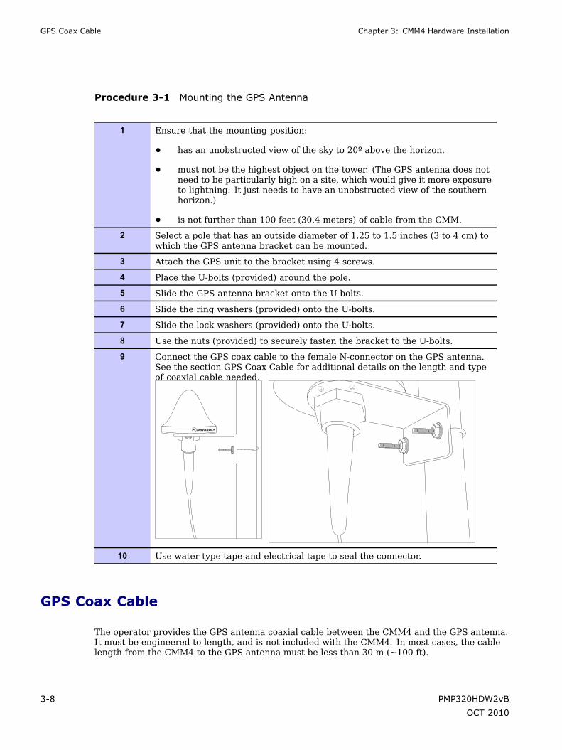
Procedure 3-1 Mounting the GPS Antenna
1 Ensure that the mounting position:
• has an unobstructed view of the sky to 20º above the horizon.
• must not be the highest object on the tower. (The GPS antenna does notneed to be particularly high on a site, which would give it more exposureto lightning. It just needs to have an unobstructed view of the southernhorizon.)
• is not further than 100 feet (30.4 meters) of cable from the CMM.
2 Select a pole that has an outside diameter of 1.25 to 1.5 inches (3 to 4 cm) towhich the GPS antenna bracket can be mounted.
3 Attach the GPS unit to the bracket using 4 screws.
4 Place the U-bolts (provided) around the pole.
5 Slide the GPS antenna bracket onto the U-bolts.
6 Slide the ring washers (provided) onto the U-bolts.
7 Slide the lock washers (provided) onto the U-bolts.
8 Use the nuts (provided) to securely fasten the bracket to the U-bolts.
9 Connect the GPS coax cable to the female N-connector on the GPS antenna.See the section GPS Coax Cable for additional details on the length and typeof coaxial cable needed.
10 Use water type tape and electrical tape to seal the connector.
GPS Coax Cable
The operator provides the GPS antenna coaxial cable between the CMM4 and the GPS antenna.It must be engineered to length, and is not included with the CMM4. In most cases, the cablelength from the CMM4 to the GPS antenna must be less than 30 m (~100 ft).
3-8 PMP320HDW2vB
OCT 2010

PMP 320 Hardware Installation GPS Coax Cable
Antenna cables can be ordered from Best-Tronics, Inc., http://best-tronics.com/motorola.htm.Antenna cables can be ordered in lengths up to 100 ft (30.4 m).
Table 3-1 Cable description
Best-Tronics Part Number Description
BT-0564 N to N GPS antenna cable
Alternatively, equivalent cables may be procured by the operator, fabricated by the operator in adepot, or fabricated at site using
• Up to 100 feet (30.4 meters) of LMR200 coaxial cable
• 2 Times Microwave N-male connectors (Times Microwave P/N TC-200-NM) or equivalentconnectors
NOTEThe CMM4 has a female N-type coax connector on the outside of the enclosure,whereas the CMM micro has a female BNC-type connector inside the enclosure. Takethis into account when ordering or fabricating cables, and when replacing a CMMmicro with a CMM4.
PMP320HDW2vB 3-9
OCT 2010

Installing the power supply for the CMM4 Chapter 3: CMM4 Hardware Installation
Installing the power supply for the CMM4■ ■ ■ ■ ■ ■ ■ ■ ■ ■ ■ ■ ■ ■ ■ ■ ■ ■ ■ ■ ■ ■ ■ ■ ■ ■ ■ ■ ■ ■ ■ ■ ■ ■ ■ ■ ■ ■ ■ ■ ■ ■ ■ ■ ■ ■ ■ ■ ■ ■ ■ ■ ■ ■ ■ ■ ■ ■ ■ ■ ■
■
■
WARNINGAlthough the output of the power supply is 29 VDC or 56 VDC, the power ratingclassifies the converter as a Class 2 electric device. For this reason, whenever youwork on power in the CMM4, you must first disconnect the DC supply from the ACpower source.
Select the appropriate procedure to install the power supply for the CMM4. Directions areprovided for a 56 VDC power supply and a procedure on how to install the 30 VDC power supply.
If using both 30 VDC and 56 VDC, a 1000 Ohm 5W resistor must be installed across the 30 VDC+V and GND at the terminal block.
56 VDC Power Supply Installation
Use the following procedure to install a 56 VDC power supply for the CMM4.
Procedure 3-2 Installing a 56 VDC Power Supply for the CMM4
1 Install the CMM4 power supply in a hut, wiring closet, or weatherizedNEMAapproved enclosure. It is designed for extreme temperatures but it isimperative to keep moisture away from the power converter.
2 Do not install the power supply within the CMM4 enclosure as it will increasethe heat within the enclosure to an unacceptable level. The CMM4 enclosureis large to provide surface area for heat dissipation without the use of forcedconvection fans, not to provide space for additional high-power electronics.
3 For the DC side of a 56 VDC power supply, engineer the DC cable, selectingthe wire gage from Table 4-1. Use either UV-resistant cable or shield thecable (as in a conduit) from UV rays.
4 Connect the DC cable on the top of the connector. Insert the +V lead intothe terminal 7 cage clamp and insert the GND (ground/return) lead into theterminal 4 cage clamp. To insert a lead into a cage clamp, insert a thin-bladescrewdriver in the secondary cage clamp hole and lever the screwdriver awayfrom the main cage clamp hole.
Continued
3-10 PMP320HDW2vB
OCT 2010
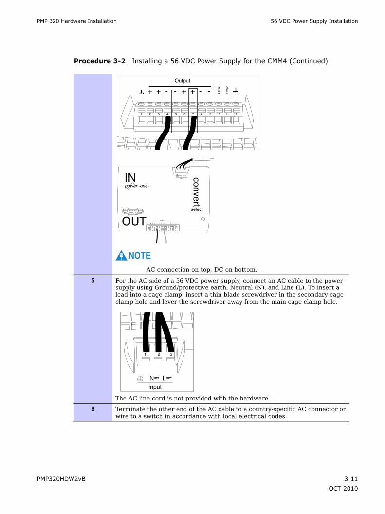
PMP 320 Hardware Installation 56 VDC Power Supply Installation
Procedure 3-2 Installing a 56 VDC Power Supply for the CMM4 (Continued)
1 2 3 4 5 6 7 8 9 10 11 12
+ + - - +Output
+ - -
AU
X 1
AU
X 2
+ + - - +Output
+ - - AU
X 1
AU
X 2
IN
select
convert
OUT
power -one-
N
Input
L
NOTEAC connection on top, DC on bottom.
5 For the AC side of a 56 VDC power supply, connect an AC cable to the powersupply using Ground/protective earth, Neutral (N), and Line (L). To insert alead into a cage clamp, insert a thin-blade screwdriver in the secondary cageclamp hole and lever the screwdriver away from the main cage clamp hole.
1 2 3
Input
N L
The AC line cord is not provided with the hardware.
6 Terminate the other end of the AC cable to a country-specific AC connector orwire to a switch in accordance with local electrical codes.
PMP320HDW2vB 3-11
OCT 2010

30 VDC Power Supply Installation Chapter 3: CMM4 Hardware Installation
30 VDC Power Supply Installation
If the PMP 320 will be co-located with PMP 100 equipment on the same CMM4, refer to theCluster Management Module 4 User Guide at http://motorola.wirelessbroadbandsupport.com/for additional information on how to install the 30 VDC power supply, and the 1000 Ohm 5 Wresistor that must be installed along with that power supply.
NOTEFor redundant power supply installation, refer to the CMM4 User guide located at:http://motorola.wirelessbroadbandsupport.com/
3-12 PMP320HDW2vB
OCT 2010

PMP 320 Hardware Installation Surge Suppressors
Surge Suppressors■ ■ ■ ■ ■ ■ ■ ■ ■ ■ ■ ■ ■ ■ ■ ■ ■ ■ ■ ■ ■ ■ ■ ■ ■ ■ ■ ■ ■ ■ ■ ■ ■ ■ ■ ■ ■ ■ ■ ■ ■ ■ ■ ■ ■ ■ ■ ■ ■ ■ ■ ■ ■ ■ ■ ■ ■ ■ ■ ■ ■
■
■
The outdoor mounting of the CMM4 requires the 600SSD, 200SSB, and in certain cases theLCOM surge suppressor. The L-COM surge suppressor is used only if the Gigabit Ethernet portis being used on the CMM4 switch. The L-COM surge suppressor can be installed in the CMM4unit. The overall installation instructions are as follows:
• ground the 600SSD and the 200SSB to Earth Ground
• connect the protected side of the 200SSB to the AC power supply SGPN4076
• connect the protected side of the 600SSD to the network switch or router in thecommunications hut.
• add drip loops at any point in the cabling where the cable changes direction.
NOTEAdditional L-COM considerations during installation: if the CMM4 unit is mounted onthe antenna and is located more that three feet away from the communications hut,an additional L-COM surge suppressor must be installed.
Figure 3-2 600SSD surge suppressor connectors
All cables must exit through the allocated slots
ETHERNETJ2 ETHERNET
J1
TRANS PROTECT
GROUND
Surge Suppressor
PMP320HDW2vB 3-13
OCT 2010

600SSD and 200SSB Surge Suppressor installation Chapter 3: CMM4 Hardware Installation
Figure 3-3 200SSD surge suppressor
+_+ _
600SSD and 200SSB Surge Suppressor installation
Use the following procedure to install the 600SSD and the 200SB surge suppressors.
CAUTIONObserve caution when drilling through the wall of the building. Ensure that there areno power lines, gas lines, water lines, or data lines in the wall at the desired locationwhere the drilling takes place.
Procedure 3-3 Surge suppressor installation and cable connections
1 Attach the surge suppressor to the communication hut near the cable accesspoint to the inside of the communications hut using two screws.
2 Remove the surge suppressor front cover to access the Ethernet RJ-45 jacks.
3 Connect the Ethernet cable from the CMM4 to the Ethernet port on the surgesuppressor port.
4
CAUTIONFollow local building codes for penetrating buildings. Observecaution when drilling through the wall of the building. Ensure thatthere are no power lines, gas lines, water lines, or data lines inthe wall at the desired location.
Continued
3-14 PMP320HDW2vB
OCT 2010
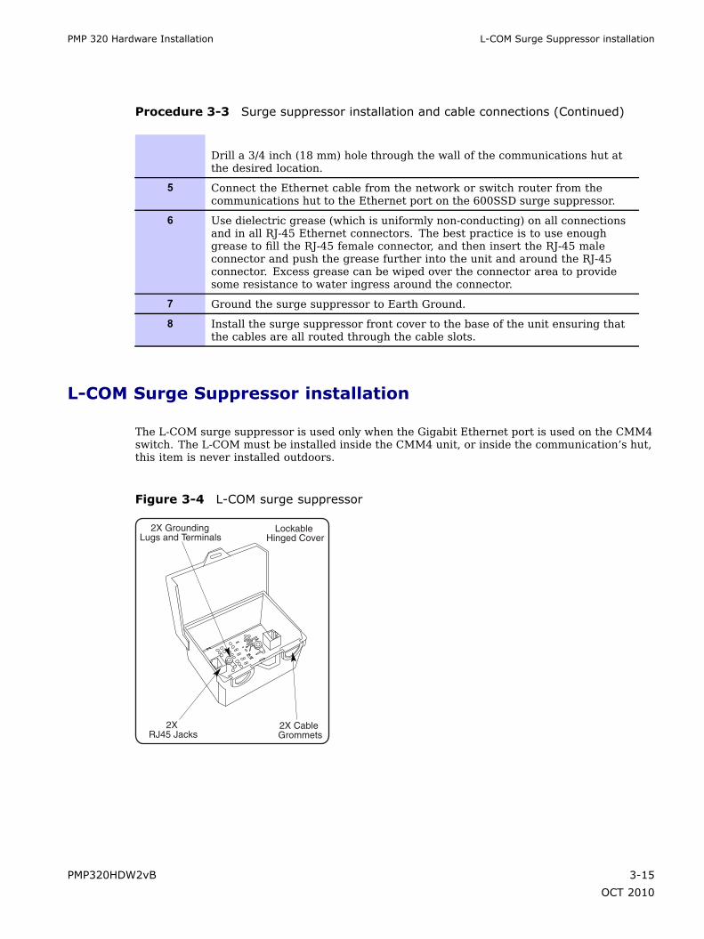
PMP 320 Hardware Installation L-COM Surge Suppressor installation
Procedure 3-3 Surge suppressor installation and cable connections (Continued)
Drill a 3/4 inch (18 mm) hole through the wall of the communications hut atthe desired location.
5 Connect the Ethernet cable from the network or switch router from thecommunications hut to the Ethernet port on the 600SSD surge suppressor.
6 Use dielectric grease (which is uniformly non-conducting) on all connectionsand in all RJ-45 Ethernet connectors. The best practice is to use enoughgrease to fill the RJ-45 female connector, and then insert the RJ-45 maleconnector and push the grease further into the unit and around the RJ-45connector. Excess grease can be wiped over the connector area to providesome resistance to water ingress around the connector.
7 Ground the surge suppressor to Earth Ground.
8 Install the surge suppressor front cover to the base of the unit ensuring thatthe cables are all routed through the cable slots.
L-COM Surge Suppressor installation
The L-COM surge suppressor is used only when the Gigabit Ethernet port is used on the CMM4switch. The L-COM must be installed inside the CMM4 unit, or inside the communication’s hut,this item is never installed outdoors.
Figure 3-4 L-COM surge suppressor
2X RJ45 Jacks
2X Cable Grommets
Lockable Hinged Cover
2X Grounding Lugs and Terminals
PMP320HDW2vB 3-15
OCT 2010

L-COM Surge Suppressor installation Chapter 3: CMM4 Hardware Installation
Procedure 3-4 L-COM surge suppressor installation
1 Determine whether the L-COM surge suppressor will be installed inside theCMM4 unit or outside the unit.
2 Remove the front cover of the surge suppressor to access the Ethernet RJ-45jacks.
3 If the unit is installed:
• inside the CMM4 unit, continue to step 4.
• outside the CMM4 unit in the communications hut, continue to step 8.
4 Place the L-COM surge suppression unit inside the CMM4 housing. Be carefulnot to place the surge suppressor in the unit as to crush any cables in theCMM4 unit or cables going through the cable glands.
5 Connect the Gigabit Ethernet connection from the CMM4 to the L-COMEthernet connector.
6 Connect the Ethernet cable from the L-COM surge suppressor and feed thecable through the cable gland on the CMM4 and connect to the switch in thecommunications hut.
7 Connect the Earth Ground on the surge suppressor to the Earth Ground in theCMM4 cabinet, continue to step 13.
8 Install the L-COM surge suppressor inside the communications hut usingtwo screws.
9 Connect the Gigabit Ethernet cable to the Ethernet cable connection in theL-COM surge suppressor.
10 Connect the Ethernet cable from the surge suppressor to the switch in thecommunications hut.
11 Connect the Ethernet cable from the CMM4 to the Ethernet port on the surgesuppressor port.
12 Connect the surge suppressor to the Earth Ground.
13 Place the cover on the L-COM unit and attach the L-COM cover.
3-16 PMP320HDW2vB
OCT 2010

PMP 320 Hardware Installation Installing the CMM4
Installing the CMM4■ ■ ■ ■ ■ ■ ■ ■ ■ ■ ■ ■ ■ ■ ■ ■ ■ ■ ■ ■ ■ ■ ■ ■ ■ ■ ■ ■ ■ ■ ■ ■ ■ ■ ■ ■ ■ ■ ■ ■ ■ ■ ■ ■ ■ ■ ■ ■ ■ ■ ■ ■ ■ ■ ■ ■ ■ ■ ■ ■ ■
■
■
Install the CMM4 outside only when temperatures are above –4° F (–20° C). The gland openingsand the bushings and inserts in the gland openings are rated for the full –40° to +131° F (–40°to +55° C) range of the CMM4. However, for dynamic operations (loosening, tightening, andinserting), they are compliant at, and rated for, only temperatures at or above –4° F (–20° C).
For more information about configuring the CMM4 device, refer to the Cluster Manager Module4 User guide located at: http://motorola.wirelessbroadbandsupport.com/software/.
When performing the installation of the CMM4 unit, remember to:
• install the CMM4 outside the communications hut whenever possible.
• do not mount the power supply inside the CMM4 enclosure.
• use 200SS for all the DC cables powering the CMM4.
• label all the CMM4 connections.
• do not accidentally toggle the default switch on the CMM4 during installation.
• use the provided glands for all connections for the CMM4.
• Use drip loops at all the transition points on all cables.
• Ensure that the pin 4 selector in the surge suppressor is set isolated (factory default).
• Connect the ground bolt on the CMM4 to the Earth Ground.
• Run the redundant power supplies on different paths
PMP320HDW2vB 3-17
OCT 2010

Installing the CMM4 Chapter 3: CMM4 Hardware Installation
Figure 3-5 CMM4 unit opened showing connection details
Cabling Diagram on Inside of Front Door
Cable Gland
Cable Housings
Prizm and Wireless Manager treat the EtherWAN Switch in a CMM4 as a generic switch. ForPrizm or Wireless Manager to correctly associate each EtherWAN Switch with its CMM4:
• before you install the CMM4, read and note the MAC address of both the CMM4 controllerand EtherWAN switch from the physical units.
• after you discover a CMM4 and its switch, use these MAC addresses for moving theswitch to the place in your Prizm or Wireless Manager network view where the CMM4was discovered.
• always maintain a record that associates these two MAC addresses.
CAUTIONWhen an EMS discovers an EtherWAN switch in your network, it can’t tell which CMM4the switch is associated with, nor can it tell CMM4 EtherWAN switches from any otherEtherWAN switches you may have in your network. The pair of MAC addresses yourecord directly from the CMM4 and its EtherWAN switch are the only means for you toestablish the logical connection.
Perform the following procedure to install the CMM4.
3-18 PMP320HDW2vB
OCT 2010
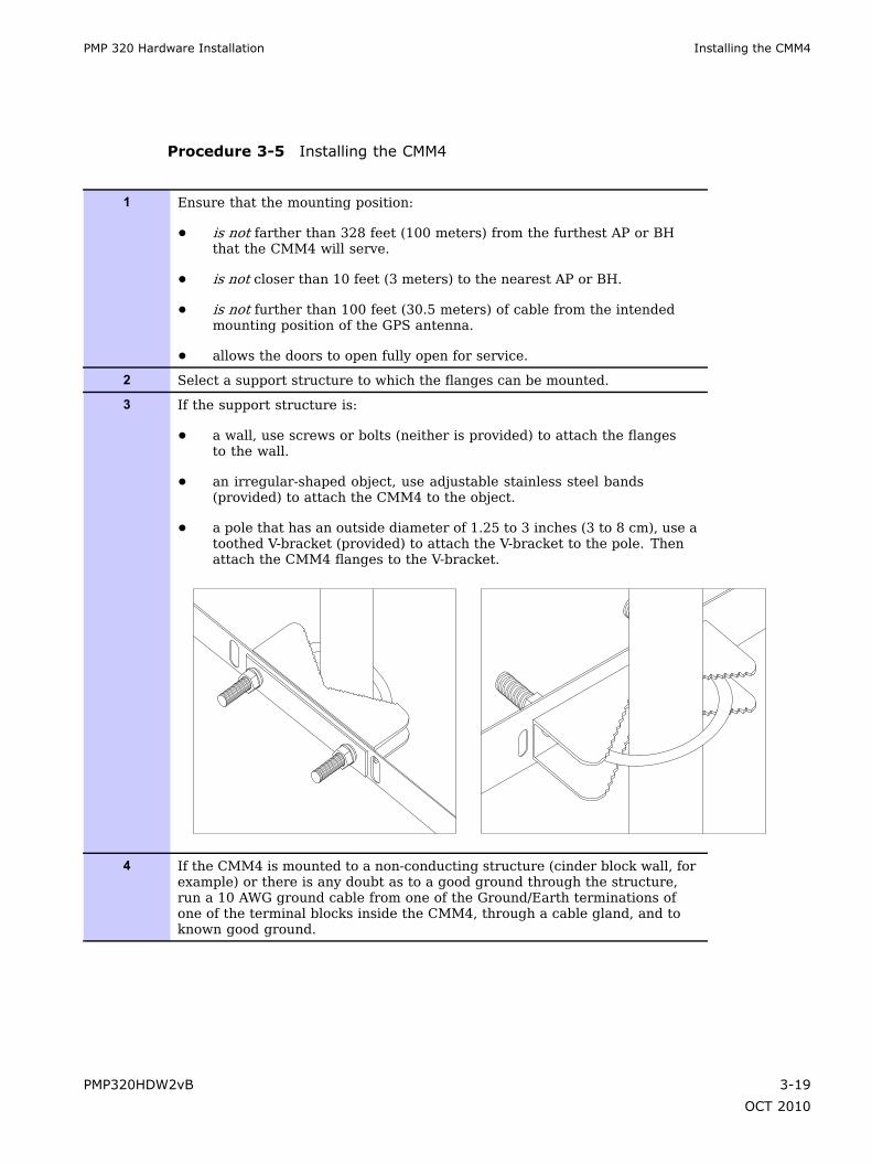
PMP 320 Hardware Installation Installing the CMM4
Procedure 3-5 Installing the CMM4
1 Ensure that the mounting position:
• is not farther than 328 feet (100 meters) from the furthest AP or BHthat the CMM4 will serve.
• is not closer than 10 feet (3 meters) to the nearest AP or BH.
• is not further than 100 feet (30.5 meters) of cable from the intendedmounting position of the GPS antenna.
• allows the doors to open fully open for service.
2 Select a support structure to which the flanges can be mounted.
3 If the support structure is:
• a wall, use screws or bolts (neither is provided) to attach the flangesto the wall.
• an irregular-shaped object, use adjustable stainless steel bands(provided) to attach the CMM4 to the object.
• a pole that has an outside diameter of 1.25 to 3 inches (3 to 8 cm), use atoothed V-bracket (provided) to attach the V-bracket to the pole. Thenattach the CMM4 flanges to the V-bracket.
4 If the CMM4 is mounted to a non-conducting structure (cinder block wall, forexample) or there is any doubt as to a good ground through the structure,run a 10 AWG ground cable from one of the Ground/Earth terminations ofone of the terminal blocks inside the CMM4, through a cable gland, and toknown good ground.
PMP320HDW2vB 3-19
OCT 2010

Cabling a CMM4 Chapter 3: CMM4 Hardware Installation
Cabling a CMM4
Figure 3-6 CMM4 connection diagram located on the door of the unit
GND (Black)
+V (Red)
NOTE: Refer to the System User Guide for the power requirement of the switch specific to the switch part number.
TOTAL 20 VDCACCESSORY POWERIS NOT TO EXCEED20 WATTS.
CMM4 CONTROLLER ( Ethernet Port View )
CMM4 CONTROLLER ( Power Port View )
EtherWAN Switch( Ethernet Port View )
EtherWAN Switch( Power Port View )
ACCESSORY POWEROUTPUTS
PO
WE
RD
EF
AU
LT
GP
S_
ME
TH
ER
NE
T P
WR
AC
TIV
ITY
LIN
KS
YN
C O
K
REDUNDANT+29 V INPUT
REDUNDANT+56 V INPUT
GN
D
PW
R
Black Red
Green
+29 VOUTPUT
+29 V INPUT
+56 V INPUT
+20 VOUTPUT
+20 VOUTPUT
+29 VOUTPUT
+56 VOUTPUT
+56 VOUTPUT
OR
DEFAULTNORMAL
AUX SYNC ETHERNET
LEDs
N ConnectorTO GPS ANTENNA
INTERNALGPS CABLE
GND GND +V GND GND +V +V GND +V GND +V GND PE+V GND
GPSRECEIVER
TOGGLESWITCH
Red
Red
Green
EXTERNALPROTECTIVE EARTH
GROUND
SHIELDED ETHERNET CABLES
1000 BaseT 1000 BaseTGreen
2
1
4
3
6
5
8
7
8
7
6
5
4
3
2
1
7
8
5
6
3
4
1
2
11
12
9
10 13 14
RS232
Twist wire pair 1 twist per inch andform three loops around ferrite corefor RF emission compliance.
Short wire to ChassisGroundat Switch mounting screwfor RF emission compliance.
CMM4 CONTROLLER
CAUTION:Damage my result if non-approvedequipment is connected to powered parts.
IMPORTANTSee the System User Guide before connectingto power. The Guide is available on-line athttp://motorola.wirelessbroadbandsupport.com/software/
www.motorola.com
P/N: 5487639D03
MAC ADDRESS IP ADDRESS
PORT 1PORT 2PORT 3PORT 4PORT 5PORT 6PORT 7PORT 8PORT 9PORT 10PORT 11PORT 12PORT 13PORT 14
3-20 PMP320HDW2vB
OCT 2010

PMP 320 Hardware Installation Cabling a CMM4
Perform the following procedure to cable the CMM4.
Procedure 3-6 Cabling the CMM4
1 Review the diagram inside the door of the CMM4. Refer to Figure 3-6.
2 The inserts in the gland openings of the CMM4 have precut holes.
3 Route Ethernet cables through the cable gland connectors to the Ethernetports inside the CMM4 cabinet (see the grey cables in the illustration).Stagger the cables as shown in the figure to make it easier to feed themthrough the gland.
EtherWAN
PWR1
LNKACT
PWR2
Continued
PMP320HDW2vB 3-21
OCT 2010
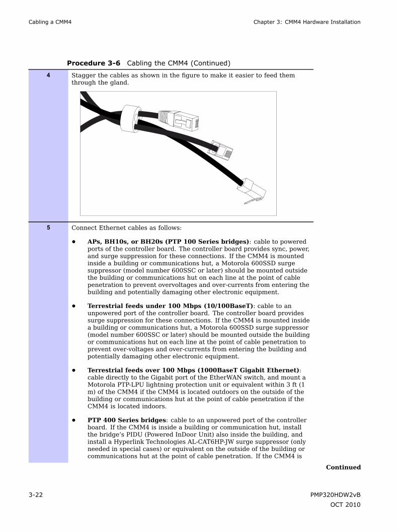
Cabling a CMM4 Chapter 3: CMM4 Hardware Installation
Procedure 3-6 Cabling the CMM4 (Continued)
4 Stagger the cables as shown in the figure to make it easier to feed themthrough the gland.
5 Connect Ethernet cables as follows:
• APs, BH10s, or BH20s (PTP 100 Series bridges): cable to poweredports of the controller board. The controller board provides sync, power,and surge suppression for these connections. If the CMM4 is mountedinside a building or communications hut, a Motorola 600SSD surgesuppressor (model number 600SSC or later) should be mounted outsidethe building or communications hut on each line at the point of cablepenetration to prevent overvoltages and over-currents from entering thebuilding and potentially damaging other electronic equipment.
• Terrestrial feeds under 100 Mbps (10/100BaseT): cable to anunpowered port of the controller board. The controller board providessurge suppression for these connections. If the CMM4 is mounted insidea building or communications hut, a Motorola 600SSD surge suppressor(model number 600SSC or later) should be mounted outside the buildingor communications hut on each line at the point of cable penetration toprevent over-voltages and over-currents from entering the building andpotentially damaging other electronic equipment.
• Terrestrial feeds over 100 Mbps (1000BaseT Gigabit Ethernet):cable directly to the Gigabit port of the EtherWAN switch, and mount aMotorola PTP-LPU lightning protection unit or equivalent within 3 ft (1m) of the CMM4 if the CMM4 is located outdoors on the outside of thebuilding or communications hut at the point of cable penetration if theCMM4 is located indoors.
• PTP 400 Series bridges: cable to an unpowered port of the controllerboard. If the CMM4 is inside a building or communication hut, installthe bridge’s PIDU (Powered InDoor Unit) also inside the building, andinstall a Hyperlink Technologies AL-CAT6HP-JW surge suppressor (onlyneeded in special cases) or equivalent on the outside of the building orcommunications hut at the point of cable penetration. If the CMM4 is
Continued
3-22 PMP320HDW2vB
OCT 2010

PMP 320 Hardware Installation LED indicators
Procedure 3-6 Cabling the CMM4 (Continued)
mounted outside, locate the PIDU in a weather-tight enclosure within 3 ft(1 m) of the CMM4 and install a Hyperlink Technologies AL-CAT6HP-JWsurge suppressor or equivalent within 3 ft (1 m) of the PIDU.
• PTP 500 and 600 Series bridges: cable directly to the Gigabitport of the EtherWAN switch. If the CMM4 is inside a building orcommunication hut, install the bridge’s PIDU (Powered InDoor Unit) alsoinside the building, and install a Hyperlink Technologies AL-CAT6HP-JWsurge suppressor or equivalent on the outside of the building orcommunications hut at the point of cable penetration. If the CMM4 ismounted outside, locate the PIDU in a weather-tight enclosure within 3 ft(1 m) of the CMM4 and install a Hyperlink Technologies AL-CAT6HP-JWsurge suppressor or equivalent within 3 ft (1 m) of the PIDU.
6 On the door label, record the MAC and IP addresses of the CMM4 and allconnected equipment.
7 Record also the MAC address of the EtherWAN switch.
8 Consistent with practices in your company, note the above information to addlater to the company equipment database.
9 Connect the coax cable from the female N-connector on the GPS antenna tothe female N-connector on the outside of the CMM4.
10 Ensure there is an Ethernet cable between the management port on thecontroller board and one of the Ethernet ports on the EtherWAN switch.
11 Feed the DC power cord through a cable gland. A 1-hole gland insert isprovided, as the DC power cable is too thick to share a gland with othercables. The 1-hole insert is either connected to one of the patch cables orincluded in the parts bag.
12 Connecting power to the terminal block:
• For 29 V: Connect the white wire to +29V on either of the 29 VDCterminal blocks. Connect the black wire to −V (GND) on the same 29VDC terminal block.
• For 56V: Connect the black and white wire to +56V on either of the 56VDC terminal blocks. Connect the black wire to –V (GND) on the same56 VDC terminal block.
13 Plug the DC power supply into an AC receptacle (AC mains).
NOTEThe AC line cord is not provided with the hardware.
14 Verify that the LEDs light.
LED indicators
The indicator LEDs color indicates position, but not the state. For example, the red PowerLED, in the left most position, lights when power is applied to the unit, but does not changecolor at any point.
PMP320HDW2vB 3-23
OCT 2010
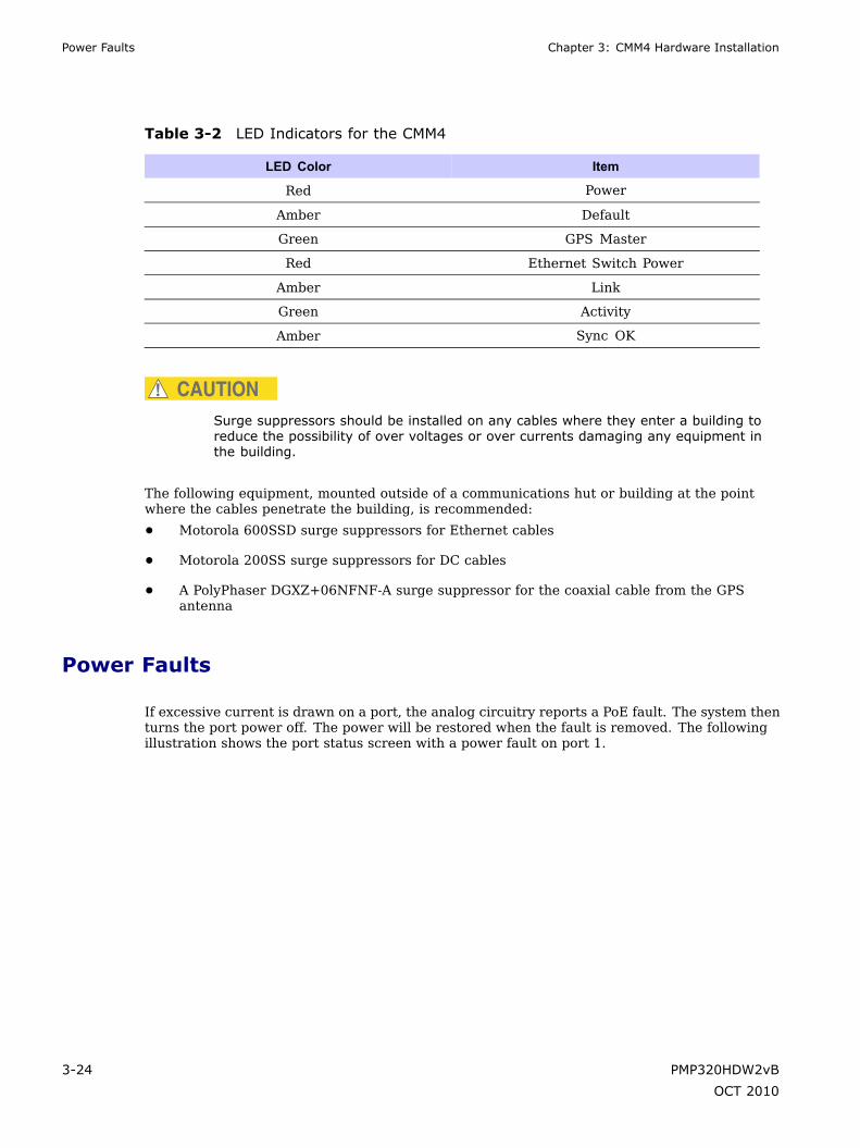
Power Faults Chapter 3: CMM4 Hardware Installation
Table 3-2 LED Indicators for the CMM4
LED Color Item
Red Power
Amber Default
Green GPS Master
Red Ethernet Switch Power
Amber Link
Green Activity
Amber Sync OK
CAUTIONSurge suppressors should be installed on any cables where they enter a building toreduce the possibility of over voltages or over currents damaging any equipment inthe building.
The following equipment, mounted outside of a communications hut or building at the pointwhere the cables penetrate the building, is recommended:
• Motorola 600SSD surge suppressors for Ethernet cables
• Motorola 200SS surge suppressors for DC cables
• A PolyPhaser DGXZ+06NFNF-A surge suppressor for the coaxial cable from the GPSantenna
Power Faults
If excessive current is drawn on a port, the analog circuitry reports a PoE fault. The system thenturns the port power off. The power will be restored when the fault is removed. The followingillustration shows the port status screen with a power fault on port 1.
3-24 PMP320HDW2vB
OCT 2010

PMP 320 Hardware Installation Configuring CMM4 ports
Figure 3-7 Port Status Showing Power Fault
Configuring CMM4 ports
To configure the ports that have been connected in this installation procedure, refer to theCMM4 User Guide located at: http://motorola.wirelessbroadbandsupport.com/software/.
Other Installation Considerations
If two CMM4 devices are synchronized together, the CMM4 that does not have a GPS needsto be set up via the GUI as a CMM slave device. Refer to the CMM4 User guide located at :http://motorola.wirelessbroadbandsupport.com/software/.
PMP320HDW2vB 3-25
OCT 2010

Other Installation Considerations Chapter 3: CMM4 Hardware Installation
3-26 PMP320HDW2vB
OCT 2010

Chapter
4
Cables■ ■ ■ ■ ■ ■ ■ ■ ■ ■ ■ ■ ■ ■ ■ ■ ■ ■ ■ ■ ■ ■ ■ ■ ■ ■ ■ ■ ■ ■ ■ ■ ■ ■ ■ ■ ■ ■ ■ ■ ■ ■ ■ ■ ■ ■ ■ ■ ■ ■ ■ ■ ■ ■ ■ ■ ■ ■ ■ ■ ■
■
■
■
■
PMP320HDW2vB 4-1
OCT 2010
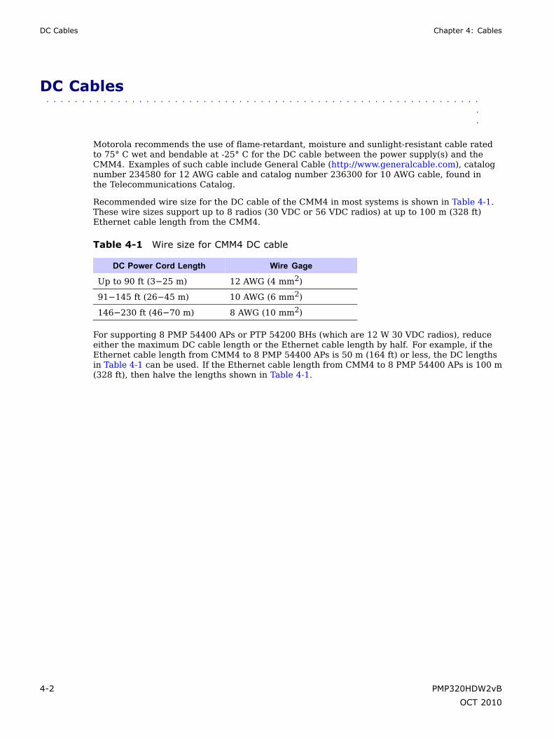
DC Cables Chapter 4: Cables
DC Cables■ ■ ■ ■ ■ ■ ■ ■ ■ ■ ■ ■ ■ ■ ■ ■ ■ ■ ■ ■ ■ ■ ■ ■ ■ ■ ■ ■ ■ ■ ■ ■ ■ ■ ■ ■ ■ ■ ■ ■ ■ ■ ■ ■ ■ ■ ■ ■ ■ ■ ■ ■ ■ ■ ■ ■ ■ ■ ■ ■ ■
■
■
Motorola recommends the use of flame-retardant, moisture and sunlight-resistant cable ratedto 75° C wet and bendable at -25° C for the DC cable between the power supply(s) and theCMM4. Examples of such cable include General Cable (http://www.generalcable.com), catalognumber 234580 for 12 AWG cable and catalog number 236300 for 10 AWG cable, found inthe Telecommunications Catalog.
Recommended wire size for the DC cable of the CMM4 in most systems is shown in Table 4-1.These wire sizes support up to 8 radios (30 VDC or 56 VDC radios) at up to 100 m (328 ft)Ethernet cable length from the CMM4.
Table 4-1 Wire size for CMM4 DC cable
DC Power Cord Length Wire Gage
Up to 90 ft (3−25 m) 12 AWG (4 mm2)
91−145 ft (26−45 m) 10 AWG (6 mm2)
146−230 ft (46−70 m) 8 AWG (10 mm2)
For supporting 8 PMP 54400 APs or PTP 54200 BHs (which are 12 W 30 VDC radios), reduceeither the maximum DC cable length or the Ethernet cable length by half. For example, if theEthernet cable length from CMM4 to 8 PMP 54400 APs is 50 m (164 ft) or less, the DC lengthsin Table 4-1 can be used. If the Ethernet cable length from CMM4 to 8 PMP 54400 APs is 100 m(328 ft), then halve the lengths shown in Table 4-1.
4-2 PMP320HDW2vB
OCT 2010

PMP 320 Hardware Installation Ethernet Cables
Ethernet Cables■ ■ ■ ■ ■ ■ ■ ■ ■ ■ ■ ■ ■ ■ ■ ■ ■ ■ ■ ■ ■ ■ ■ ■ ■ ■ ■ ■ ■ ■ ■ ■ ■ ■ ■ ■ ■ ■ ■ ■ ■ ■ ■ ■ ■ ■ ■ ■ ■ ■ ■ ■ ■ ■ ■ ■ ■ ■ ■ ■ ■
■
■
The operator provides the Ethernet cables between the CMM4 and the radios it supports. Theymust be engineered to length and are not included with the CMM4. The cable length from theCMM4 to any radio must be under 100 m (328 ft).
Cables are available from Best-Tronics, Inc., http://best-tronics.com/motorola.htm. These cablescan be ordered in lengths up to 328 ft (100 m) and are listed in the following tables.
Table 4-2 Recommended Ethernet Cables
Typical Use Best-Tronics Part Number Description
Infrastructure Ethernetcable
BT-0781S-XXX RJ-45 to RJ-45 straight,shielded, UV-resistantEthernet cable using outdoorSTP Cat 5e cable, lower costthan plenum-rated, availableonly in black.
Infrastructure Ethernetcable for plenums
BT-0562S-XXX RJ-45 to RJ-45 straight,shielded, UV-resistant,plenum-rated Ethernet cableusing outdoor STP Cat 5ecable, available in beige,blue, grey, or white.
NOTEShielded Ethernet cable is strongly recommended for AP and BH installations.
Alternatively, equivalent cables may be procured by the operator, fabricated by the operator in adepot, or fabricated at site. The modules have auto MDX/MDIX and so either straight-throughor crossover Ethernet cables may be used. Pinouts for straight-through cables are shownthe following figures.
PMP320HDW2vB 4-3
OCT 2010

Ethernet Cables Chapter 4: Cables
Figure 4-1 RJ-45 Straight-through connections
Table 4-3 Recommended Ethernet Cables
Pin Color
1 white / orange
2 orange
3 white / green
4 blue
5 white / blue
6 green
7 white / brown
8 brown
Figure 4-2 Pin 1 Location diagram
(Lock t a b u n d e r n e a th )
← Pin 1
Bulk unterminated Ethernet cable can be ordered from Best-Tronics as bulk cable:
• CA-0287S: (shielded, plenum rated)
• CA-0367S: (lower cost, shielded, non-plenum-rated)
4-4 PMP320HDW2vB
OCT 2010

PMP 320 Hardware Installation CMM Sync Cable
CMM Sync Cable■ ■ ■ ■ ■ ■ ■ ■ ■ ■ ■ ■ ■ ■ ■ ■ ■ ■ ■ ■ ■ ■ ■ ■ ■ ■ ■ ■ ■ ■ ■ ■ ■ ■ ■ ■ ■ ■ ■ ■ ■ ■ ■ ■ ■ ■ ■ ■ ■ ■ ■ ■ ■ ■ ■ ■ ■ ■ ■ ■ ■
■
■
Two CMMs (two CMMmicros, two CMM4s, or a CMMmicro and a CMM4) can be connectedtogether with a CMM sync cable to provide either
• The ability to have one GPS antenna support two CMMs
• Warm spare redundant sync
Pinouts for the CMM sync cable are shown in the following figures. Figure 4-4 shows thelocation of Pin 1, relative to the lock tab on the connector.
NOTEThe CMM sync cable used to connect two CMMs for sync purposes has differentpinouts than the straight-through sync cable used to connect a “remote AP” to an SM,or an AP or BHM to a CMM2.
PMP320HDW2vB 4-5
OCT 2010

CMM Sync Cable Chapter 4: Cables
Figure 4-3 CMM sync cable pinouts
Figure 4-4 CMM sync cable pinouts
(Lock tab is on other side)
← Pin 1
4-6 PMP320HDW2vB
OCT 2010

PMP 320 Hardware Installation AP default plug
AP default plug■ ■ ■ ■ ■ ■ ■ ■ ■ ■ ■ ■ ■ ■ ■ ■ ■ ■ ■ ■ ■ ■ ■ ■ ■ ■ ■ ■ ■ ■ ■ ■ ■ ■ ■ ■ ■ ■ ■ ■ ■ ■ ■ ■ ■ ■ ■ ■ ■ ■ ■ ■ ■ ■ ■ ■ ■ ■ ■ ■ ■
■
■
If resetting the AP to the factory default settings, a default plug can be used to force the AP toreturn to the Factory default setting 1. The action of inserting the default plug into the AUXjack of the AP resets all AP parameters except for the password. The IP address of the APis reset to http://192.168.2.101.
If the operator does not recall the password for the AP after the AP has been reset, then the APwill have to be removed from the tower and sent back to the manufacturer.
The AP senses for the default plug at all times, so the default plug is used only when the APmust be reset. Use the following procedure to reset the AP.
The default plug can be ordered through Best-Tronics or use the following constructed on sitefrom the procedure provided in this section.
The RJ–11 default plug can be ordered from Best-Tronics, or constructed using the procedureprovided in this section, refer to . If ordering the default plug from Best-Tronics the part numberto order is BT-0583 at http://www.best-tronics.com/motorola1.htm. The Best-Tronics catalogprovides information that the IP address is set to a certain IP address. The actual IP addressthat the AP is reset to is http://192.168.2.101 using the default plug on the PMP 320 AP.
The AP must be rebooted in order for the Restore Point 1 to take effect.
Constructing a AP default plug
This section provides information on how to construct an override default plug. Make sure touse an RJ–12 and not an RJ–11 connector. (The difference is there are six brass tabs instead offour on the RJ–12) RJ–11 connectors are physically the same size as an RJ–12 connector, butwill not work.
The constructed override plug resets the LAN 1 IP address to 192.168.2.101. The plug allowsthe operator to access the module through the default configuration without changing theconfiguration. The operator can then view and reset any non-default values.
The following pin information provides color of the wire and the signal information for each pin:
• pin 1 white / orange (GPS sync)
• pin 2 white / green (Serial Tx 9600)
• pin 3 white / blue (Serial RX 9600)
• pin 4 green (Default Jumper)
• pin 5 blue (Audio /GPS Power sync)
• pin 6 orange (Ground)
Use the following procedure to fabricate an override default plug.
PMP320HDW2vB 4-7
OCT 2010

Constructing a AP default plug Chapter 4: Cables
Procedure 4-1 Constructing a default plug
1 Install an RJ-12 6-pin connector onto a 6-inch length of CAT 5 cable.
2 Pin out all 6-pins on one end of the RJ-12 connector.
3 Short (solder or twist together) pins 4 and 6 on the other end of the CAT 5cable. Do not connect any other wires to anything. The result should be asfollows:
• Pin 1 ® white / orange ¬ pin 1
• Pin 2 ® white / green ¬ pin 2
• Pin 3 ® white / blue ¬ pin 3
• Pin 4 ® green ¬ pin 6
• Pin 5 ® blue ¬ pin 5
• Pin 6 ® orange¬ pin 4
4 Wrap the exposed wires with a shrink tube.
RJ-12 ConnectorCAT 5 Cable
BT-0583
LabelShrinkwrap
4-8 PMP320HDW2vB
OCT 2010

Chapter
5
Integrated CSM Hardware Installation■ ■ ■ ■ ■ ■ ■ ■ ■ ■ ■ ■ ■ ■ ■ ■ ■ ■ ■ ■ ■ ■ ■ ■ ■ ■ ■ ■ ■ ■ ■ ■ ■ ■ ■ ■ ■ ■ ■ ■ ■ ■ ■ ■ ■ ■ ■ ■ ■ ■ ■ ■ ■ ■ ■ ■ ■ ■ ■ ■ ■
■
■
■
■
This chapter provides the instructions and procedures used to:
• connect the Integrated CSM device to a pole or wall
• pre-power up alignment for level of service connection
• cable the unit
• ground the unit
• add surge suppression
• post power up connection
• IP connectivity alignment correction
CAUTIONThe orientation of the Integrated CSM when installed is important. The face of theCSM with the Motorola logo must be pointing in the direction of the antenna facingoutwards from the building. The Ethernet connector must be oriented so it is on thebottom right corner of the CSM.
Figure 5-1 Integrated CSM (CPE) 320 Identification
Canopy CSM 320
Front RearEthernet Connector
PMP320HDW2vB 5-1
OCT 2010

Before you begin Chapter 5: Integrated CSM Hardware Installation
Before you begin■ ■ ■ ■ ■ ■ ■ ■ ■ ■ ■ ■ ■ ■ ■ ■ ■ ■ ■ ■ ■ ■ ■ ■ ■ ■ ■ ■ ■ ■ ■ ■ ■ ■ ■ ■ ■ ■ ■ ■ ■ ■ ■ ■ ■ ■ ■ ■ ■ ■ ■ ■ ■ ■ ■ ■ ■ ■ ■ ■ ■
■
■
This section describes items that the installer or subscriber must purchase before installingthe Integrated CSM. This section also describes items that must be available and points toconsider before beginning the CSM installation.
5-2 PMP320HDW2vB
OCT 2010
PMP 320 Hardware Installation Additional material required for installation
Additional material required for installation
The additional materials required for installation are as follows:
• The computer of the subscriber must be equipped with an Ethernet network interfacecard (NIC).
NOTEThe NIC is not provided with the Integrated CSM, but subscribers can purchasea NIC at most computer and electronics stores.
• An RJ–45 Ethernet cable to connect the Integrated CSM plug-in power supply to thecomputer.
• Ground wire of sufficient length to run between the CSM and the home ground point.
NOTE
• It is recommended that the ground wire is a 6 AWG, solid copper wire.
• It is recommended that if a ground rod is used it should be an 8 ft (2.5m) copper rod.
• Most buildings have an existing ground rod outside, at the main powerconnection site. If desired, a rod can be installed into the ground outsidethe building after consulting the local electrical codes.
• The AC line cord is not provided with the hardware. Acquire theappropriate power line cord for the country where the unit is installed.
• Lead screw anchors if the Integrated CSM is mounted on a brick or masonry surface.
• Outdoor rated category 5e Ethernet cable to connect the Integrated CSM plug-in powersupply through the building wall to the CSM.
• RJ–45 plug connectors and the tools required for field termination of the category 5e cable
• Grommet to cover a 3/4 inch. (18 mm) hole
• Silicone or acrylic caulking
• Water-proof tape
• Power supply for the PowerDsine power supply
• Electrical tape
Pre-installation planning
While on the ground, find an appropriate location outside the building to mount the IntegratedCSM.
PMP320HDW2vB 5-3
OCT 2010

Components shipped with the Integrated CSM Chapter 5: Integrated CSM Hardware Installation
NOTETo provide Internet service, the Integrated CSM communicates with a base stationon the communications tower of the service provider. Information about the nearestcommunications tower is provided by the service provider. For example, if the towernearest to the building is towards the north of the building, install the IntegratedCSM on the north side of the building.
After determining the optimal side of the building, select an Integrated CSM mounting point ata high location on the building such as under the eaves.
Components shipped with the Integrated CSM
Locate the components shipped with the Integrated CSM device. The parts list for theIntegrated CSM installation consists of the following items:
Table 5-1 Integrated CSM parts list
Component Quantity
Integrated CSM 320 device(vertical)
1
Bracket base mounting 1
Bracket Bottom Mounting 1
Bracket Top Mounting 1
Middle mounting bracket 1
M8 (50 mm) hex head bolt 2
M8 (100 mm) bolt 2
M8 split washer 13
M8 washer 11
M8 nut 3
M5 (35 mm) set screw 2
M4 (16 mm) bolt 4
M4 split washer 4
M4 washer 4
ENET cable 1
NOTEThe PowerDsine power supply does not include a power cord.
5-4 PMP320HDW2vB
OCT 2010

PMP 320 Hardware Installation Cabling Overview
Figure 5-2 Integrated CSM components
M8 NutM8 Split WasherM8 Washer
2X M8 Nut4X M8 Split Washer4X M8 Washer
4X M4 x 16MM Bolt4X M4 Split Washer4X M4 Washer
Bracket Base Mounting
2X M8 x 100 MM Bolt
Bracket Bottom Mounting
M5 Set Screw 35MMM8 Split Washer
M5 Set Screw 35MMM8 Split Washer
M8 x 50 MM BoltM8 Split Washer M8 Washer
M8 x 50 MM BoltM8 Split Washer M8 Washer
Bracket Top Mounting
CSM320
MiddleMounting bracket
Mounting Pole(Reference)
Cabling Overview
The following items are not supplied with the system:
• Ground wire
• Grounding rod
• Outdoor power/Ethernet cable
• Ethernet cable
• Computer NIC
Figure 5-3 illustrates the routing of the ground wire, the category 5e Ethernet cable, andthe Integrated CSM power/Ethernet cable.
PMP320HDW2vB 5-5
OCT 2010

Cabling Overview Chapter 5: Integrated CSM Hardware Installation
Figure 5-3 Integrated CSM mounted to a wall
Building’s Roof
Bui
ldin
g’s
wal
l
CPE Bracketassembly attached to
building's exterior
to householdgrounding point
Dsine
Ethernet cable(not supplied)
Subscriber’sComputer
Ground wire(not supplied)
Surge Suppressor
CPE Power/Ethernetcable
5-6 PMP320HDW2vB
OCT 2010

PMP 320 Hardware Installation Installing the Integrated CSM
Installing the Integrated CSM■ ■ ■ ■ ■ ■ ■ ■ ■ ■ ■ ■ ■ ■ ■ ■ ■ ■ ■ ■ ■ ■ ■ ■ ■ ■ ■ ■ ■ ■ ■ ■ ■ ■ ■ ■ ■ ■ ■ ■ ■ ■ ■ ■ ■ ■ ■ ■ ■ ■ ■ ■ ■ ■ ■ ■ ■ ■ ■ ■ ■
■
■
This section describes how to find an appropriate installation location for the Integrated CSM,and how to install the Integrated CSM on the building.
Selecting a location for the Integrated CSM
Determine the optimum installation location for the Integrated CSM before physically mountingthe Integrated CSM to the building.
Most often, if the Integrated CSM is mounted on the side of the building facing the base stationof the service provider, the Integrated CSM can detect adequate signal to provide high-speedInternet access. However, unless there is an obvious line of sight to the correct base station, thecorrect orientation of the Integrated CSM is often not apparent. There may also be practicalreasons why the Integrated CSM cannot be mounted on the side of the building that facesthe base station.
Procedure 5-1 Selecting an installation location for the Integrated CSM
1 Using a laptop and a temporary power source connected to the IntegratedCSM locate the optimal site for the Integrated CSM to be installed.Refer to the PMP 320 Administration and Configuration Guide foradditional information on accessing the CSM GUI and status settings.http://motorola.wirelessbroadbandsupport.com/software/
2 Start by pointing the front of the Integrated CSM in the direction that ismost likely to be optimal.
3 Try pointing the Integrated CSM in different directions. If required, performthis task while standing in the upper stories or on the roof of the building. Ateach elevation and in each direction the Integrated CSM is pointed.
4 After determining the place where the best signal can be detected usingthe CSM GUI screen information, choose a corresponding Integrated CSMinstallation location on the building.
NOTEThe Integrated CSM can be mounted either directly on the buildingor on a pole.
PMP320HDW2vB 5-7
OCT 2010

Installation Overview Chapter 5: Integrated CSM Hardware Installation
Installation Overview■ ■ ■ ■ ■ ■ ■ ■ ■ ■ ■ ■ ■ ■ ■ ■ ■ ■ ■ ■ ■ ■ ■ ■ ■ ■ ■ ■ ■ ■ ■ ■ ■ ■ ■ ■ ■ ■ ■ ■ ■ ■ ■ ■ ■ ■ ■ ■ ■ ■ ■ ■ ■ ■ ■ ■ ■ ■ ■ ■ ■
■
■
After finding the best installation location on the building, perform the following procedure toinstall the Integrated CSM.
Procedure 5-2 Installing the Integrated CSM
1 Complete the mounting bracket assembly; leave the screws on the bracketarm slightly loose. If the screws are too tight, the vertical and horizontal tiltof the Integrated CSM cannot be adjusted later.
NOTEIf fastening the Integrated CSM to a pole, add the pole clamp to theassembly. Otherwise, set the pole clamp aside.
2 Perform one of the following:
1. If attaching the Integrated CSM to the side of a building, attach theIntegrated CSM to the building using the wall bracket of the bracketassembly.
2. Mount the Integrated CSM to a pole using the wall bracket and poleclamp of the bracket assembly.
3 Adjust the vertical and horizontal tilt of the Integrated CSM so that it canobtain the best signal.
4 Fully tighten the bracket assembly into the desired position.
Completing the mounting bracket assembly
Perform the following procedure to complete the mounting bracket assembly. Refer toFigure 5-2 to reference the brackets and the assembly of the brackets.
Procedure 5-3 Mounting bracket assembly
1 Attach one end of the bracket arm to the arch on this wall bracket.
2 Insert a 5/16×1½ hex bolt into the arch of the wall bracket that was attachedto the Integrated CSM in step 1. Ensure that the head of the medium hex boltrests inside the bolt jam of the arch.
3 Guide the rest of the bolt through the arch of the wall bracket.
4 Slide a tooth lock washer on the end of the hex bolt.
Continued
5-8 PMP320HDW2vB
OCT 2010
PMP 320 Hardware Installation Attaching the Integrated CSM and mounting the bracket assembly outside the building
Procedure 5-3 Mounting bracket assembly (Continued)
5 Align the hole on one tab of the bracket arm with the end of the bolt.
6 Slide the bracket arm tab onto the bolt, and then place a flat washer over theend of the bolt.
7 Tighten the end of the bolt with a hex nut. Leave the hex nut loose enough sothat the vertical tilt of the Integrated CSM can be adjusted later.
8 Attach the other end of the bracket arm to the second wall bracket.
9 Insert a 5/16×1½ hex bolt into the arch of the second wall bracket. Thisbracket is attached to the wall or clamped to a pole.
NOTEEnsure that the head of the hex bolt rests inside the bolt jam foundon the arch. When the assembly is complete, ensure that the boltjam is facing the ground.
10 Guide the rest of the bolt through the arch of the wall bracket.
11 Slide a tooth lock washer at the end of the hex bolt.
12 Align the hole on the tab of the bracket arm with the end of the bolt.
13 Slide the tab of the bracket arm onto the bolt, and then place a flat washerover the end of the bolt.
14 Tighten the end of the bolt with a hex nut. Leave the hex nut loose enough sothat the horizontal tilt of the Integrated CSM can be adjusted later.
15 If fastening the Integrated CSM to a pole, loosely attach the clamp to wallbracket 2. Perform the steps listed in the section Fastening the IntegratedCSM and mounting the bracket assembly to a pole.
Attaching the Integrated CSM and mounting the bracketassembly outside the building
WARNINGMaintain a safe distance from RF exposure at least 50 cm (20 inches) when installingthe Integrated CSM to the subscriber building. Maintain safe distances from powerlines.
Perform the following procedure to attach the Integrated CSM to the outside of the building.
PMP320HDW2vB 5-9
OCT 2010
Fastening the Integrated CSM and mounting the bracket assembly to a pole Chapter 5:Integrated CSM Hardware Installation
Procedure 5-4 Attaching the Integrated CSM and mounting the bracket assemblyoutside the building
1 Where possible, install the Integrated CSM on the side of the building that hasthe greatest exposure to the communications tower of the service provider.The service provider can provide information about tower locations that canprovide the Integrated CSM with the greatest signal exposure.
2 Drill holes into the exterior wall of the building where the Integrated CSMmust be hung.
• Drill the two top holes 2.5 inches apart. Drill the bottom holes 2.5 inchesbelow the top holes.
• If possible, drill one upper hole and its corresponding lower hole intoa stud. Do not allow the Integrated CSM to be supported by the sidingof the building.
• If installing the Integrated CSM on a brick or masonry surface, useappropriate anchors.
CAUTIONObserve caution when drilling through the wall of the building.Ensure that there are no power lines, gas lines, water lines, or datalines in the wall at the desired location where the drilling takes place.
3 After the holes are drilled into the building, drive the screws through theholes on the wall bracket and into the building. While attaching the bracketassembly to the wall, ensure that the bottom of the Integrated CSM ispointing towards the ground. The bottom of the Integrated CSM is the sidewith the Ethernet connector and the grounding lug. The Integrated CSMmust be installed vertically.
Fastening the Integrated CSM and mounting the bracketassembly to a pole
If fastening the Integrated CSM to a pole, add the pole clamp to the assembly. Perform thefollowing procedure to fasten the Integrated CSM to a pole.
5-10 PMP320HDW2vB
OCT 2010

PMP 320 Hardware Installation Fastening the Integrated CSM and mounting the bracket assembly to a pole
Procedure 5-5 Fastening the Integrated CSM and mounting the bracket assemblyto a pole
1 Insert the following through the holes on the clamp:
• Large hex bolt
• Large split washer
• Large washer
2 Place the clamp around the pole.
3 Align the screw assembly with the center holes on the wall bracket.
4 Tighten the clamp so that the bracket assembly and the attached IntegratedCSM are tight on the pole.
PMP320HDW2vB 5-11
OCT 2010

Aligning the Integrated CSM for best signal strength Chapter 5: Integrated CSM Hardware Installation
Aligning the Integrated CSM for best signal strength■ ■ ■ ■ ■ ■ ■ ■ ■ ■ ■ ■ ■ ■ ■ ■ ■ ■ ■ ■ ■ ■ ■ ■ ■ ■ ■ ■ ■ ■ ■ ■ ■ ■ ■ ■ ■ ■ ■ ■ ■ ■ ■ ■ ■ ■ ■ ■ ■ ■ ■ ■ ■ ■ ■ ■ ■ ■ ■ ■ ■
■
■
NOTEThis alignment procedure assumes that the installer has reviewed the siteinterference values collected for the area of the installation.
The bolts connecting the two pole/wall brackets to the bracket arm are not yet fully tightened.Hence, use the bracket arm to adjust the vertical and horizontal tilt of the Integrated CSM. Thisadjustment helps the Integrated CSM to obtain the strongest signal from the service provider.
Perform the following procedure to adjust the vertical and horizontal tilts of the Integrated CSM.
Procedure 5-6 Adjusting the vertical and horizontal tilt of the Integrated CSM forlevel of service connection
1 Temporarily apply power to the Integrated CSM to adjust the Integrated CSM forsignal strength.
NOTEDo not connect to the consumer computer at this time.
The AC line cord is not provided with the hardware. Acquire theappropriate power line cord for the country where the unit is installed.
2 Connect an Ethernet cable to the Integrated CSM and to a laptop.
3 Log into the CSM GUI application to view the status of the signal strength of theIntegrated CSM unit. Enter the following default user name and password IDs:
• Login ID - operator
• Password - wimax
4 Adjust the Integrated CSM by rotating the Integrated CSM to the left and right.Find the position of the Integrated CSM where the CSM GUI indicates the strongestsignal strength to the unit. Verify the signal strength on the status page of theCSM GUI screen.
Continued
5-12 PMP320HDW2vB
OCT 2010
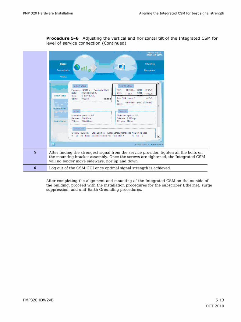
PMP 320 Hardware Installation Aligning the Integrated CSM for best signal strength
Procedure 5-6 Adjusting the vertical and horizontal tilt of the Integrated CSM forlevel of service connection (Continued)
5 After finding the strongest signal from the service provider, tighten all the bolts onthe mounting bracket assembly. Once the screws are tightened, the Integrated CSMwill no longer move sideways, nor up and down.
6 Log out of the CSM GUI once optimal signal strength is achieved.
After completing the alignment and mounting of the Integrated CSM on the outside ofthe building, proceed with the installation procedures for the subscriber Ethernet, surgesuppression, and unit Earth Grounding procedures.
PMP320HDW2vB 5-13
OCT 2010
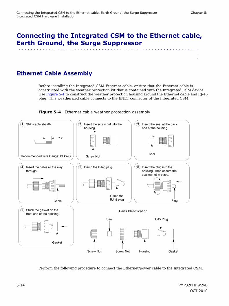
Connecting the Integrated CSM to the Ethernet cable, Earth Ground, the Surge Suppressor Chapter 5:Integrated CSM Hardware Installation
Connecting the Integrated CSM to the Ethernet cable,Earth Ground, the Surge Suppressor
■ ■ ■ ■ ■ ■ ■ ■ ■ ■ ■ ■ ■ ■ ■ ■ ■ ■ ■ ■ ■ ■ ■ ■ ■ ■ ■ ■ ■ ■ ■ ■ ■ ■ ■ ■ ■ ■ ■ ■ ■ ■ ■ ■ ■ ■ ■ ■ ■ ■ ■ ■ ■ ■ ■ ■ ■ ■ ■ ■ ■
■
■
Ethernet Cable Assembly
Before installing the Integrated CSM Ethernet cable, ensure that the Ethernet cable isconstructed with the weather protection kit that is contained with the Integrated CSM device.Use Figure 5-4 to construct the weather protection housing around the Ethernet cable and RJ-45plug. This weatherized cable connects to the ENET connector of the Integrated CSM.
Figure 5-4 Ethernet cable weather protection assembly
Parts Identification
RJ45 Plug
GasketScrew Nut Screw Nut
Seal
Housing
Gasket
Strick the gasket on thefront end of the housing.
7
Plug
6 Insert the plug into thehousing. Then secure thesealing nut in place.
5 Crimp the RJ45 plug.
Crimp theRJ45 plug
4 Insert the cable all the waythrough.
Cable
Seal
3 Insert the seal at the backend of the housing.
2 Insert the screw nut into thehousing.
Screw Nut
1 Strip cable sheath.
7.7
Recommended wire Gauge: 24AWG
Perform the following procedure to connect the Ethernet/power cable to the Integrated CSM.
5-14 PMP320HDW2vB
OCT 2010

PMP 320 Hardware Installation Ethernet Cable Assembly
Procedure 5-7 Connecting the Ethernet cable to the Integrated CSM
1 Cut the required length of the outdoor-rated Category-5 Ethernet cable forthe chosen installation site. The maximum cable length is 100 m (~330 ft).
2 Terminate the cable using standard RJ–45 connectors using the procedure asshown in Figure 5-4.
Use dielectric grease (which is uniformly non-conducting) on all connectionsand in all RJ–45 Ethernet connectors. The best practice is to use enoughgrease to fill the RJ–45 female connector, and then insert the RJ-45 maleconnector and push the grease further into the unit and around the RJ–45connector. Excess grease can be wiped over the connector area to providesome resistance to water ingress around the connector.
3 Wrap a drip-loop in the cable at any point where the cable changes direction.
4 Measure the cable so it will span from the Integrated CSM to the surgesuppressor box.
5 Fasten the cable to the building according to local building codes.
NOTECables that move in the wind can be damaged, impart vibrations tothe connected device, or both. At installation time, prevent theseproblems by securing all cables with cable ties, cleats, or weatherresistant tape. The cable can be a path for water to follow to enterthe cable connector or even the module. Prevent this problemby including and securing a drip loop where the cable enters thebuilding.
PMP320HDW2vB 5-15
OCT 2010

Running cables through the wall of the building Chapter 5: Integrated CSM Hardware Installation
Running cables through the wall of the building■ ■ ■ ■ ■ ■ ■ ■ ■ ■ ■ ■ ■ ■ ■ ■ ■ ■ ■ ■ ■ ■ ■ ■ ■ ■ ■ ■ ■ ■ ■ ■ ■ ■ ■ ■ ■ ■ ■ ■ ■ ■ ■ ■ ■ ■ ■ ■ ■ ■ ■ ■ ■ ■ ■ ■ ■ ■ ■ ■ ■
■
■
The power/Ethernet cable runs from inside the building to the Integrated CSM. The followingprocedure describes how to run the cables through the wall of the building.
CAUTIONObserve caution when drilling through the wall of the building. Ensure that there areno power lines, gas lines, water lines, or data lines in the wall at the desired locationwhere the drilling takes place.
Procedure 5-8 Running cables through the wall of the building
1
CAUTIONFollow local building codes for penetrating buildings. Observecaution when drilling through the wall of the building. Ensure thatthere are no power lines, gas lines, water lines, or data lines inthe wall at the desired location.
Drill a 3/4 inch. (18 mm) hole through the wall at the desired location.
2 Draw one end of the category 5e cable through the hole.
3 Route the category 5e power/Ethernet cable from the surge suppressor to thelocation where the power supply is to be plugged in.
4 After completing the installation, use a grommet for the hole and seal the holewith a silicone or acrylic caulking material.
5-16 PMP320HDW2vB
OCT 2010
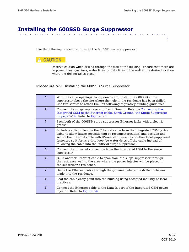
PMP 320 Hardware Installation Installing the 600SSD Surge Suppressor
Installing the 600SSD Surge Suppressor■ ■ ■ ■ ■ ■ ■ ■ ■ ■ ■ ■ ■ ■ ■ ■ ■ ■ ■ ■ ■ ■ ■ ■ ■ ■ ■ ■ ■ ■ ■ ■ ■ ■ ■ ■ ■ ■ ■ ■ ■ ■ ■ ■ ■ ■ ■ ■ ■ ■ ■ ■ ■ ■ ■ ■ ■ ■ ■ ■ ■
■
■
Use the following procedure to install the 600SSD Surge suppressor.
CAUTIONObserve caution when drilling through the wall of the building. Ensure that there areno power lines, gas lines, water lines, or data lines in the wall at the desired locationwhere the drilling takes place.
Procedure 5-9 Installing the 600SSD Surge Suppressor
1 With the cable openings facing downward, install the 600SSD surgesuppressor above the site where the hole in the residence has been drilled.Use two screws to attach the unit following regulatory building guidelines.
2 Connect the surge suppressor to Earth Ground. Refer to Connecting theIntegrated CSM to the Ethernet cable, Earth Ground, the Surge Suppressoron page 5-14. Refer to Figure 5-5.
3 Pack both of the 600SSD surge suppressor Ethernet jacks with dielectricgrease.
4 Include a splicing loop in the Ethernet cable from the Integrated CSM (extracable to allow future repositioning or reconnectorization) and position andsecure the Ethernet cable with UV-resistant wire ties or other locally-approvedfasteners so it forms a drip loop (so water drips off the cable instead offollowing the cable into the 600SSD surge suppressor).
5 Connect the Ethernet connection from the Integrated CSM to the surgesuppressor.
6 Build another Ethernet cable to span from the surge suppressor throughthe residence wall to the area where the power injector will be placed inthe subscriber’s residence.
7 Guide the Ethernet cable through the grommet where the drilled hole wasmade into the residence.
8 Seal the cable entry point into the building using accepted industry or localpractices.
9 Connect the Ethernet cable to the Data In port of the Integrated CSM powerinjector. Refer to Figure 5-6.
PMP320HDW2vB 5-17
OCT 2010

Connecting the ground wire Chapter 5: Integrated CSM Hardware Installation
Figure 5-5 Cable connections from the surge suppressor to the Integrated CSMpower injector and the Integrated CSM
All cables must exit through the allocated slots
ETHERNETJ2 ETHERNET
J1
TRANS PROTECT
GROUND
Surge Suppressor
Figure 5-6 Integrated CSM 320 power injector
AC
PORT
DATA & POWER DATA
INOUT
AC POWER
Connecting the ground wire
The Integrated CSM must be grounded to a household ground point or to a grounding rodaccording to the applicable electrical code. Equipment grounding practices vary with localbuilding codes and established practices of the service provider. Following is the IntegratedCSM grounding procedure as recommended by Motorola. The ground wire must be a minimumof 18 AWG, with 14 AWG recommended for runs up to 45 m (~150 ft) and 10 AWG recommendedfor runs over 45 m (~150 ft) .
5-18 PMP320HDW2vB
OCT 2010

PMP 320 Hardware Installation Connecting the power supply and the Ethernet cable to the computer
NOTEIf not using an existing approved grounding system, install a grounding system(Protective Earth) according to applicable regulations or codes.
Ground the Integrated CSM using one of the following methods:
• If grounding an Integrated CSM installed below the roof line, connect the Integrated CSMto the ground point of the building. Then attach all wires to the building using electricalstaples. Use drip loops as required.
• If grounding an Integrated CSM that is installed above the roof line, then perform thefollowing:
Connect the ground wire from the Integrated CSM/surge suppressor to the groundrod in the ground next to the building.
Connect the ground rod to the household ground point according to the applicableelectrical code.
Attach all wires to the building using electrical staples. Use drip loops as required.
Use the following procedure to ground the Integrated CSM at the residence premises.
Procedure 5-10 Grounding the Integrated CSM
1 Wrap the AWG 10 (6mm2) copper ground wire around the ground post ofthe Integrated CSM.
2 Remove the cover of the 600SSD surge suppressor.
3 Wrap the AWG 10 (6mm2) copper ground wire around the ground post ofthe 600SSD.
4 Tighten the ground post locking nut.
5 Ensure the pin 4 selector in the 600SSD is set to the factory default ofisolated, not grounded.
6 If not using an existing approved grounding system, install a groundingsystem (Protective Earth) according to applicable regulations or codes.
7 Connect the ground wire from the Integrated CSM and the 600SS to EarthGround.
Connecting the power supply and the Ethernet cable to thecomputer
Perform the following procedure to connect the power supply and the Ethernet cables.
PMP320HDW2vB 5-19
OCT 2010
Connecting the power supply and the Ethernet cable to the computer Chapter 5: Integrated CSM Hardware Installation
Procedure 5-11 Connecting the power supply
1 Plug the category 5e cord from the Integrated CSM/surge suppressor intothe jack labeled AC Power on the Integrated CSM Power Injector (if thisconnection is not already made).
2 Connect the protected side of the 600SSD surge suppressor cable to the Data& Power Out port of the Integrated CSM power injector.
3 Use a standard category 5e Ethernet cable to connect the computer to thejack labeled computer on the power supply.
NOTEThe cable to the Integrated CSM provides both the power andthe Ethernet connection. The cable is compatible with the IEEEStandard 802.3af power over Ethernet.
4 The power cord uses standard household power. Plug the power cord in theAC power source.
NOTEThe AC line cord is not provided with the hardware. Acquire theappropriate power line cord for the country where the unit isinstalled.
Figure 5-6 illustrates the cable connection through the data line protector and into the powersupply cord.
5-20 PMP320HDW2vB
OCT 2010

Chapter
6
Connectorized CSM Hardware Installation■ ■ ■ ■ ■ ■ ■ ■ ■ ■ ■ ■ ■ ■ ■ ■ ■ ■ ■ ■ ■ ■ ■ ■ ■ ■ ■ ■ ■ ■ ■ ■ ■ ■ ■ ■ ■ ■ ■ ■ ■ ■ ■ ■ ■ ■ ■ ■ ■ ■ ■ ■ ■ ■ ■ ■ ■ ■ ■ ■ ■
■
■
■
■
This chapter provides the instructions and procedures used to:
• connect the Connectorized CSM device to a pole or wall
• cable the unit
• connect the antenna cables to the unit
• ground the unit
• add surge suppression
• post power up connection
CAUTIONThe orientation of the Connectorized CSM is not as important as the placement ofthe Connectorized CSM antennas. The Connectorized CSM can be installed in aneasily accessible area, and must be installed with the Motorola logo in a horizontalposition as shown in Figure 6-1. Install the Connectorized CSM where the Ethernetconnector and N-type connectors are oriented so they positioned on the bottom of theConnectorized CSM as seen in Figure 6-1.
For OMNI antennas: either one or two antennas can be mounted with the CSM. Forcustomers that are looking for an additional 3 dB of diversity gain, two antennas canbe mounted vertically. Note, that MIMO B is not supported with the OMNI antennas.
PMP320HDW2vB 6-1
OCT 2010
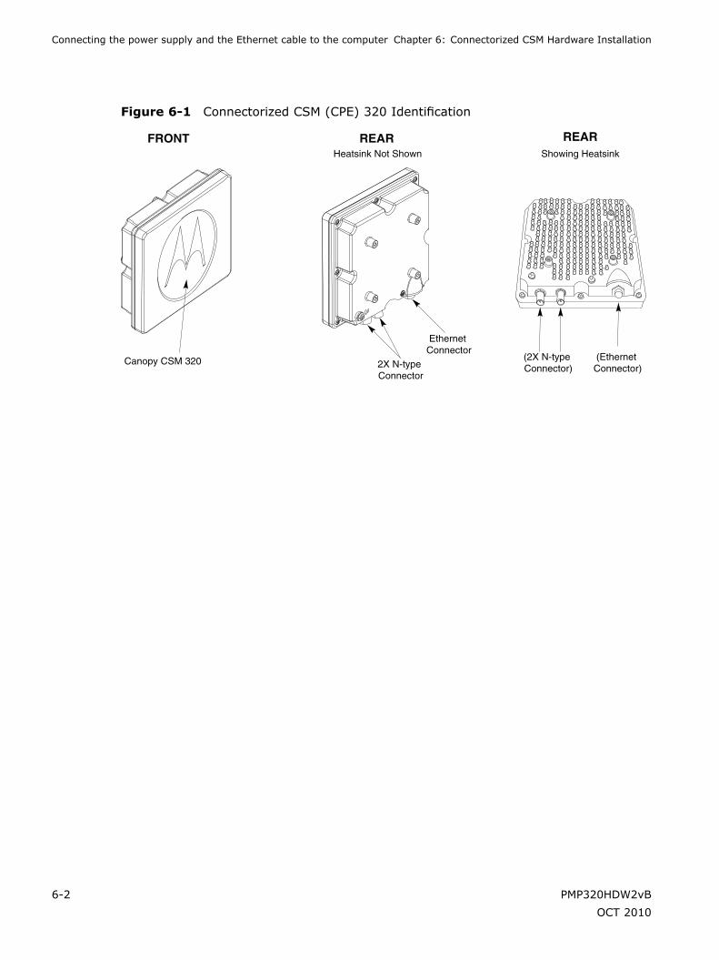
Connecting the power supply and the Ethernet cable to the computer Chapter 6: Connectorized CSM Hardware Installation
Figure 6-1 Connectorized CSM (CPE) 320 Identification
Canopy CSM 320
FRONT REAR REARShowing HeatsinkHeatsink Not Shown
(Ethernet Connector)
Ethernet Connector
(2X N-type Connector)2X N-type
Connector
6-2 PMP320HDW2vB
OCT 2010
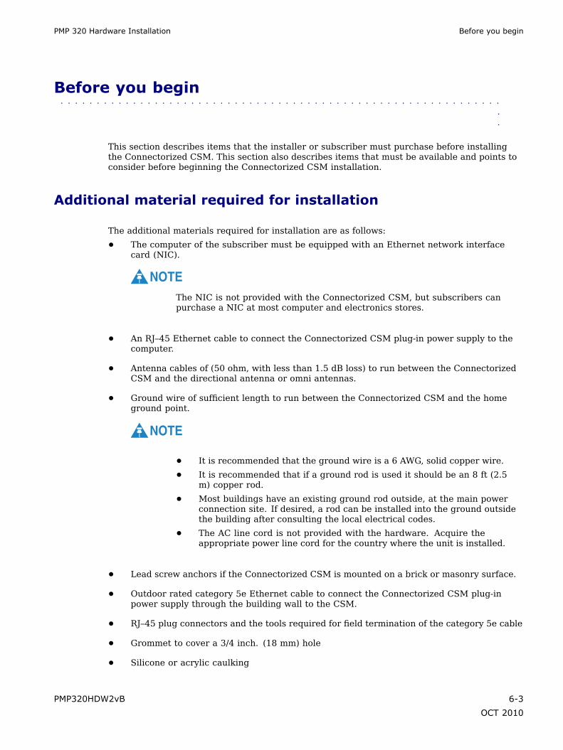
PMP 320 Hardware Installation Before you begin
Before you begin■ ■ ■ ■ ■ ■ ■ ■ ■ ■ ■ ■ ■ ■ ■ ■ ■ ■ ■ ■ ■ ■ ■ ■ ■ ■ ■ ■ ■ ■ ■ ■ ■ ■ ■ ■ ■ ■ ■ ■ ■ ■ ■ ■ ■ ■ ■ ■ ■ ■ ■ ■ ■ ■ ■ ■ ■ ■ ■ ■ ■
■
■
This section describes items that the installer or subscriber must purchase before installingthe Connectorized CSM. This section also describes items that must be available and points toconsider before beginning the Connectorized CSM installation.
Additional material required for installation
The additional materials required for installation are as follows:
• The computer of the subscriber must be equipped with an Ethernet network interfacecard (NIC).
NOTEThe NIC is not provided with the Connectorized CSM, but subscribers canpurchase a NIC at most computer and electronics stores.
• An RJ–45 Ethernet cable to connect the Connectorized CSM plug-in power supply to thecomputer.
• Antenna cables of (50 ohm, with less than 1.5 dB loss) to run between the ConnectorizedCSM and the directional antenna or omni antennas.
• Ground wire of sufficient length to run between the Connectorized CSM and the homeground point.
NOTE
• It is recommended that the ground wire is a 6 AWG, solid copper wire.
• It is recommended that if a ground rod is used it should be an 8 ft (2.5m) copper rod.
• Most buildings have an existing ground rod outside, at the main powerconnection site. If desired, a rod can be installed into the ground outsidethe building after consulting the local electrical codes.
• The AC line cord is not provided with the hardware. Acquire theappropriate power line cord for the country where the unit is installed.
• Lead screw anchors if the Connectorized CSM is mounted on a brick or masonry surface.
• Outdoor rated category 5e Ethernet cable to connect the Connectorized CSM plug-inpower supply through the building wall to the CSM.
• RJ–45 plug connectors and the tools required for field termination of the category 5e cable
• Grommet to cover a 3/4 inch. (18 mm) hole
• Silicone or acrylic caulking
PMP320HDW2vB 6-3
OCT 2010
Pre-installation planning Chapter 6: Connectorized CSM Hardware Installation
• Waterproof tape
• Electrical tape
• 50 ohm low loss cable
• N-type connectors
Connectorized CSM Antenna Requirements
Pre-installation planning
While on the ground, find an appropriate location outside the building to mount theConnectorized CSM and antennas.
NOTEInformation about the nearest communications tower is provided by the serviceprovider. For example, if the tower nearest to the building is towards the north ofthe building, install the Connectorized CSM antenna or antennas on the appropriateside of the building.
After determining the optimal side of the building, select a Connectorized CSM antennamounting point at a high location on the building such as under the eaves. The ConnectorizedCSM does not have to be mounted near the antennas. Ensure that the installation of theConnectorized CSM and the antennas provide less than 1.5 dB cable loss. Refer to the localinstallation guides on the best location for the Connectorized CSM placement.
Components shipped with the Connectorized CSM
Locate the components shipped with the Connectorized CSM device. The parts list for theConnectorized CSM installation consists of the following items:
6-4 PMP320HDW2vB
OCT 2010

PMP 320 Hardware Installation Components shipped with the Connectorized CSM
Table 6-1 Connectorized CSM parts list
Component Quantity
Connectorized CSM 320device
1
Bracket base mounting 1
Bracket Bottom Mounting 1
Bracket Top Mounting 1
Middle mounting bracket 1
M8 (50 mm) hex head bolt 2
M8 (100 mm) bolt 2
M8 split washer 13
M8 washer 11
M8 nut 3
M5 (35 mm) set screw 2
M4 (16 mm) bolt 4
M4 split washer 4
M4 washer 4
Dsign power supply 1
ENET cable 1
PMP320HDW2vB 6-5
OCT 2010

Cabling Overview Chapter 6: Connectorized CSM Hardware Installation
Figure 6-2 CSM components
M8 NutM8 Split WasherM8 Washer
2X M8 Nut4X M8 Split Washer4X M8 Washer
4X M4 x 16MM Bolt4X M4 Split Washer4X M4 Washer
Bracket Base Mounting
2X M8 x 100 MM Bolt
Bracket Bottom Mounting
M5 Set Screw 35MMM8 Split Washer
M5 Set Screw 35MMM8 Split Washer
M8 x 50 MM BoltM8 Split Washer M8 Washer
M8 x 50 MM BoltM8 Split Washer M8 Washer
Bracket Top Mounting
CSM320
CSM320(Actual Rear View
with Heat Sink shown)
MiddleMounting bracket
Mounting Pole(Reference)
Cabling Overview
The following items are not supplied with the system:
• Ground wire
• Grounding rod
• Outdoor power/Ethernet cable
• Outdoor antenna cables
• Ethernet cable
• Computer NIC
• Antenna cables
Figure 6-3 illustrates the routing of the ground wire, the category 5e Ethernet cable, thelocation of the antenna cable connections, and the Connectorized CSM power/Ethernet cable.
6-6 PMP320HDW2vB
OCT 2010

PMP 320 Hardware Installation Cabling Overview
Figure 6-3 Connectorized CSM mounted to a wall
Building’s Roof
Bui
ldin
g’s
wal
l
CPE Bracketassembly attached to
building's exterior
to householdgrounding point
Dsine
Ethernet cable(not supplied)
Subscriber’sComputer
Ground wire(not supplied)
Surge Suppressor
CPE Power/Ethernet
cable
N-Connectorsto Antenna
PMP320HDW2vB 6-7
OCT 2010

Installation Overview Chapter 6: Connectorized CSM Hardware Installation
Installation Overview■ ■ ■ ■ ■ ■ ■ ■ ■ ■ ■ ■ ■ ■ ■ ■ ■ ■ ■ ■ ■ ■ ■ ■ ■ ■ ■ ■ ■ ■ ■ ■ ■ ■ ■ ■ ■ ■ ■ ■ ■ ■ ■ ■ ■ ■ ■ ■ ■ ■ ■ ■ ■ ■ ■ ■ ■ ■ ■ ■ ■
■
■
After finding the best installation location on the building, perform the following procedureto install the Connectorized CSM.
Procedure 6-1 Installing the Connectorized CSM
1 Complete the mounting bracket assembly; leave the screws on the bracketarm slightly loose. If the screws are too tight, the vertical and horizontal tiltof the Connectorized CSM cannot be adjusted later.
NOTEIf fastening the Connectorized CSM to a pole, add the pole clamp tothe assembly. Otherwise, set the pole clamp aside.
2 Perform one of the following:
1. If attaching the Connectorized CSM to the side of a building, attachthe Connectorized CSM to the building using the wall bracket of thebracket assembly.
2. Mount the Connectorized CSM to a pole using the wall bracket and poleclamp of the bracket assembly.
3 Fully tighten the bracket assembly into the desired position.
Completing the mounting bracket assembly
Perform the following procedure to complete the mounting bracket assembly. Refer toFigure 6-2 to reference the brackets and the assembly of the brackets.
Procedure 6-2 Mounting bracket assembly
1 Attach one end of the bracket arm to the arch on this wall bracket.
2 Insert a 5/16×1½ hex bolt into the arch of the wall bracket that was attachedto the Connectorized CSM in step 1. Ensure that the head of the medium hexbolt rests inside the bolt jam of the arch.
3 Guide the rest of the bolt through the arch of the wall bracket.
4 Slide a tooth lock washer on the end of the hex bolt.
5 Align the hole on one tab of the bracket arm with the end of the bolt.
Continued
6-8 PMP320HDW2vB
OCT 2010

PMP 320 Hardware Installation Attaching the Connectorized CSM and mounting the bracket assembly outside the building
Procedure 6-2 Mounting bracket assembly (Continued)
6 Slide the bracket arm tab onto the bolt, and then place a flat washer over theend of the bolt.
7 Tighten the end of the bolt with a hex nut. Leave the hex nut loose enough sothat the vertical tilt of the Connectorized CSM can be adjusted later.
8 Attach the other end of the bracket arm to the second wall bracket.
9 Insert a 5/16×1½ hex bolt into the arch of the second wall bracket. Thisbracket is attached to the wall or clamped to a pole.
NOTEEnsure that the head of the hex bolt rests inside the bolt jam foundon the arch. When the assembly is complete, ensure that the boltjam is facing the ground.
10 Guide the rest of the bolt through the arch of the wall bracket.
11 Slide a tooth lock washer at the end of the hex bolt.
12 Align the hole on the tab of the bracket arm with the end of the bolt.
13 Slide the tab of the bracket arm onto the bolt, and then place a flat washerover the end of the bolt.
14 Tighten the end of the bolt with a hex nut. Leave the hex nut loose enough sothat the horizontal tilt of the Connectorized CSM can be adjusted later.
15 If fastening the Connectorized CSM to a pole, loosely attach the clamp to wallbracket 2. Perform the steps listed in the section Fastening the ConnectorizedCSM and mounting the bracket assembly to a pole.
Attaching the Connectorized CSM and mounting the bracketassembly outside the building
WARNINGMaintain a safe distance from RF exposure at least 50 cm (20 inches) when installingthe Connectorized CSM to the subscriber building. Maintain safe distances from powerlines.
Perform the following procedure to attach the Connectorized CSM to the outside of the building.
PMP320HDW2vB 6-9
OCT 2010

Fastening the Connectorized CSM and mounting the bracket assembly to a pole Chapter6: Connectorized CSM Hardware Installation
Procedure 6-3 Attaching the Connectorized CSM and mounting the bracket assemblyoutside the building
1 Install the Connectorized CSM at the site following local regulations forinstallation location requirements. The Connectorized CSM does not haveto be installed within line of site of the communications tower, but must beinstalled at the site and connected to the Connectorized CSM antenna.
2 Drill holes into the exterior wall of the building where the ConnectorizedCSM must be hung.
• Drill the two top holes 2.5 inches apart. Drill the bottom holes 2.5 inchesbelow the top holes.
• If possible, drill one upper hole and its corresponding lower hole intoa stud. Do not allow the Connectorized CSM to be supported by thesiding of the building.
• If installing the Connectorized CSM on a brick or masonry surface, useappropriate anchors.
CAUTIONObserve caution when drilling through the wall of the building.Ensure that there are no power lines, gas lines, water lines, or datalines in the wall at the desired location where the drilling takes place.
3 After the holes are drilled into the building, drive the screws through theholes on the wall bracket and into the building. While attaching the bracketassembly to the wall, ensure that the bottom of the Connectorized CSM ispointing towards the ground. The bottom of the Connectorized CSM is theside with the Ethernet and N-type connectors and the grounding lug. TheConnectorized CSM must be installed horizontally.
Fastening the Connectorized CSM and mounting the bracketassembly to a pole
If fastening the Connectorized CSM to a pole, add the pole clamp to the assembly. Perform thefollowing procedure to fasten the Connectorized CSM to a pole.
6-10 PMP320HDW2vB
OCT 2010
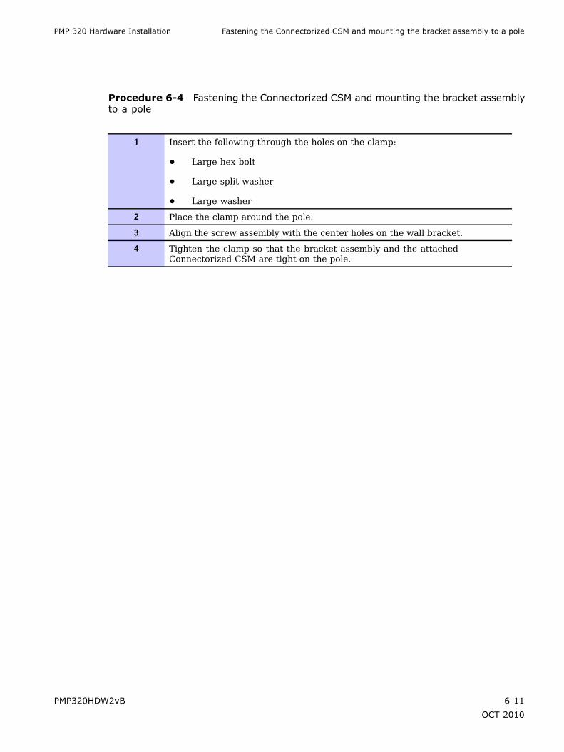
PMP 320 Hardware Installation Fastening the Connectorized CSM and mounting the bracket assembly to a pole
Procedure 6-4 Fastening the Connectorized CSM and mounting the bracket assemblyto a pole
1 Insert the following through the holes on the clamp:
• Large hex bolt
• Large split washer
• Large washer
2 Place the clamp around the pole.
3 Align the screw assembly with the center holes on the wall bracket.
4 Tighten the clamp so that the bracket assembly and the attachedConnectorized CSM are tight on the pole.
PMP320HDW2vB 6-11
OCT 2010

Connecting the Antenna Cables to the Unit Chapter 6: Connectorized CSM Hardware Installation
Connecting the Antenna Cables to the Unit■ ■ ■ ■ ■ ■ ■ ■ ■ ■ ■ ■ ■ ■ ■ ■ ■ ■ ■ ■ ■ ■ ■ ■ ■ ■ ■ ■ ■ ■ ■ ■ ■ ■ ■ ■ ■ ■ ■ ■ ■ ■ ■ ■ ■ ■ ■ ■ ■ ■ ■ ■ ■ ■ ■ ■ ■ ■ ■ ■ ■
■
■
Use the following procedure to connect the antenna cables to the unit. Depending uponthe type of antenna used, either two omni antennas, or one diagonal polarized antenna, theconnectors from the installed antennas must be connected to the Connectorized CSM unitN-type connectors.
Use a 50 ohm outdoor cable with less than 1.5 dB of loss for the antenna connections.
For additional information regarding antenna information refer to Table 7-3.
Figure 6-4 Connectorized CSM antenna cable connector location
G1_ccsm_ant_connid.eps
MAIN
Ethernet
BOTTOM VIEW
N-Type Antenna ConnectorsGround
Procedure 6-5 Connecting the Antenna Cables to the Connectorized CSM whenusing an Omni Antenna
1 Ensure that drip loops are in place before connecting the antenna cable to theConnectorized CSM.
2 Using a 50 ohm low loss cable with an N-type connector, connect the endof the cable from the Omni antenna connector to the Connectorized CSMN-type connector. Refer to Figure 6-4 for cable connection location on theConnectorized CSM.
3 Use waterproof tape and electrical tape on all N-type connectors on theantennas and the Connectorized CSM connections.
4 Repeat step 2 for the second Omni antenna.
6-12 PMP320HDW2vB
OCT 2010

PMP 320 Hardware Installation Connecting the Antenna Cables to the Unit
Procedure 6-6 Connecting the Antenna Cables to the Connectorized CSM when usingan Diagonal Polarized Antenna
1 Ensure that drip loops are in place before connecting the antenna cable to theConnectorized CSM.
2 Using a 50 ohm low loss cable with an N-type connector, connect the N-typeconnector to the V-polarity connector of the antenna to the ConnectorizedCSM N-type connector. Refer to Figure 6-4 for cable connection locationon the Connectorized CSM.
3 Use waterproof tape and electrical tape on all N-type connectors on theantennas and the Connectorized CSM connections.
4 Using the other 50 ohm cable, connect the N-type connector to the H-polarityconnector of the antenna to the Connectorized CSM N-type connector.
PMP320HDW2vB 6-13
OCT 2010

Connecting the Connectorized CSM to the Ethernet cable, Earth Ground, the Surge Suppressor Chapter6: Connectorized CSM Hardware Installation
Connecting the Connectorized CSM to the Ethernetcable, Earth Ground, the Surge Suppressor
■ ■ ■ ■ ■ ■ ■ ■ ■ ■ ■ ■ ■ ■ ■ ■ ■ ■ ■ ■ ■ ■ ■ ■ ■ ■ ■ ■ ■ ■ ■ ■ ■ ■ ■ ■ ■ ■ ■ ■ ■ ■ ■ ■ ■ ■ ■ ■ ■ ■ ■ ■ ■ ■ ■ ■ ■ ■ ■ ■ ■
■
■
Ethernet Cable Assembly
Before installing the Connectorized CSM Ethernet cable, ensure that the Ethernet cable isconstructed with the weather protection kit that is contained with the Connectorized CSMdevice. Use Figure 6-5 to construct the weather protection housing around the Ethernet cableand RJ-45 plug. This weatherized cable connects to the ENET connector of the ConnectorizedCSM.
Figure 6-5 Ethernet cable weather protection assembly
Parts Identification
RJ45 Plug
GasketScrew Nut Screw Nut
Seal
Housing
Gasket
Strick the gasket on thefront end of the housing.
7
Plug
6 Insert the plug into thehousing. Then secure thesealing nut in place.
5 Crimp the RJ45 plug.
Crimp theRJ45 plug
4 Insert the cable all the waythrough.
Cable
Seal
3 Insert the seal at the backend of the housing.
2 Insert the screw nut into thehousing.
Screw Nut
1 Strip cable sheath.
7.7
Recommended wire Gauge: 24AWG
Perform the following procedure to connect the Ethernet/power cable to the Connectorized CSM.
6-14 PMP320HDW2vB
OCT 2010
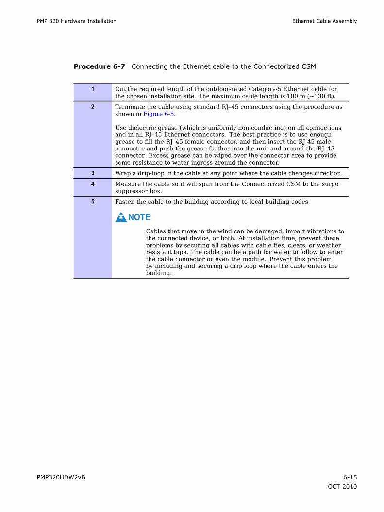
PMP 320 Hardware Installation Ethernet Cable Assembly
Procedure 6-7 Connecting the Ethernet cable to the Connectorized CSM
1 Cut the required length of the outdoor-rated Category-5 Ethernet cable forthe chosen installation site. The maximum cable length is 100 m (~330 ft).
2 Terminate the cable using standard RJ–45 connectors using the procedure asshown in Figure 6-5.
Use dielectric grease (which is uniformly non-conducting) on all connectionsand in all RJ–45 Ethernet connectors. The best practice is to use enoughgrease to fill the RJ–45 female connector, and then insert the RJ-45 maleconnector and push the grease further into the unit and around the RJ–45connector. Excess grease can be wiped over the connector area to providesome resistance to water ingress around the connector.
3 Wrap a drip-loop in the cable at any point where the cable changes direction.
4 Measure the cable so it will span from the Connectorized CSM to the surgesuppressor box.
5 Fasten the cable to the building according to local building codes.
NOTECables that move in the wind can be damaged, impart vibrations tothe connected device, or both. At installation time, prevent theseproblems by securing all cables with cable ties, cleats, or weatherresistant tape. The cable can be a path for water to follow to enterthe cable connector or even the module. Prevent this problemby including and securing a drip loop where the cable enters thebuilding.
PMP320HDW2vB 6-15
OCT 2010
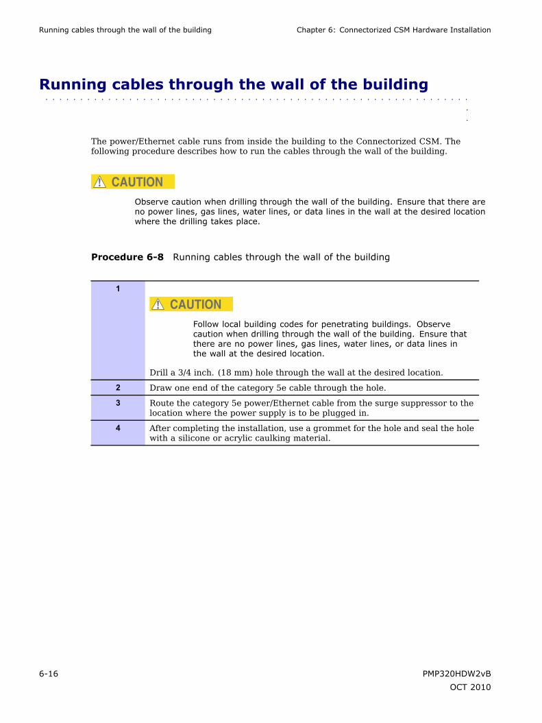
Running cables through the wall of the building Chapter 6: Connectorized CSM Hardware Installation
Running cables through the wall of the building■ ■ ■ ■ ■ ■ ■ ■ ■ ■ ■ ■ ■ ■ ■ ■ ■ ■ ■ ■ ■ ■ ■ ■ ■ ■ ■ ■ ■ ■ ■ ■ ■ ■ ■ ■ ■ ■ ■ ■ ■ ■ ■ ■ ■ ■ ■ ■ ■ ■ ■ ■ ■ ■ ■ ■ ■ ■ ■ ■ ■
■
■
The power/Ethernet cable runs from inside the building to the Connectorized CSM. Thefollowing procedure describes how to run the cables through the wall of the building.
CAUTIONObserve caution when drilling through the wall of the building. Ensure that there areno power lines, gas lines, water lines, or data lines in the wall at the desired locationwhere the drilling takes place.
Procedure 6-8 Running cables through the wall of the building
1
CAUTIONFollow local building codes for penetrating buildings. Observecaution when drilling through the wall of the building. Ensure thatthere are no power lines, gas lines, water lines, or data lines inthe wall at the desired location.
Drill a 3/4 inch. (18 mm) hole through the wall at the desired location.
2 Draw one end of the category 5e cable through the hole.
3 Route the category 5e power/Ethernet cable from the surge suppressor to thelocation where the power supply is to be plugged in.
4 After completing the installation, use a grommet for the hole and seal the holewith a silicone or acrylic caulking material.
6-16 PMP320HDW2vB
OCT 2010

PMP 320 Hardware Installation Installing the 600SSD Surge Suppressor
Installing the 600SSD Surge Suppressor■ ■ ■ ■ ■ ■ ■ ■ ■ ■ ■ ■ ■ ■ ■ ■ ■ ■ ■ ■ ■ ■ ■ ■ ■ ■ ■ ■ ■ ■ ■ ■ ■ ■ ■ ■ ■ ■ ■ ■ ■ ■ ■ ■ ■ ■ ■ ■ ■ ■ ■ ■ ■ ■ ■ ■ ■ ■ ■ ■ ■
■
■
Use the following procedure to install the 600SSD Surge suppressor.
CAUTIONObserve caution when drilling through the wall of the building. Ensure that there areno power lines, gas lines, water lines, or data lines in the wall at the desired locationwhere the drilling takes place.
Procedure 6-9 Installing the 600SSD Surge Suppressor
1 With the cable openings facing downward, install the 600SSD surgesuppressor above the site where the hole in the residence has been drilled.Use two screws to attach the unit following regulatory building guidelines.
2 Connect the surge suppressor to Earth Ground. Refer to Connecting theIntegrated CSM to the Ethernet cable, Earth Ground, the Surge Suppressoron page 5-14. Refer to Figure 6-6.
3 Pack both of the 600SSD surge suppressor Ethernet jacks with dielectricgrease.
4 Include a splicing loop in the Ethernet cable from the ConnectorizedCSM (extra cable to allow future repositioning or reconnectorization) andposition and secure the Ethernet cable with UV-resistant wire ties or otherlocally-approved fasteners so it forms a drip loop (so water drips off the cableinstead of following the cable into the 600SSD surge suppressor).
5 Connect the Ethernet connection from the Connectorized CSM to the surgesuppressor.
6 Build another Ethernet cable to span from the surge suppressor throughthe residence wall to the area where the power injector will be placed inthe subscriber’s residence.
7 Guide the Ethernet cable through the grommet where the drilled hole wasmade into the residence.
8 Seal the cable entry point into the building using accepted industry or localpractices.
9 Connect the Ethernet cable to the Data In port of the Connectorized CSMpower injector. Refer to Figure 6-7.
PMP320HDW2vB 6-17
OCT 2010

Connecting the ground wire Chapter 6: Connectorized CSM Hardware Installation
Figure 6-6 Cable connections from the surge suppressor to the Connectorized CSMpower injector and the Connectorized CSM
All cables must exit through the allocated slots
ETHERNETJ2 ETHERNET
J1
TRANS PROTECT
GROUND
Surge Suppressor
Figure 6-7 Connectorized CSM 320 power injector
AC
PORT
DATA & POWER DATA
INOUT
AC POWER
Connecting the ground wire
The Connectorized CSM must be grounded to a household ground point or to a grounding rodaccording to the applicable electrical code. Equipment grounding practices vary with localbuilding codes and established practices of the service provider. Following is the ConnectorizedCSM grounding procedure as recommended by Motorola. The ground wire must be a minimumof 18 AWG, with 14 AWG recommended for runs up to 45 m (~150 ft) and 10 AWG recommendedfor runs over 45 m (~150 ft) .
6-18 PMP320HDW2vB
OCT 2010
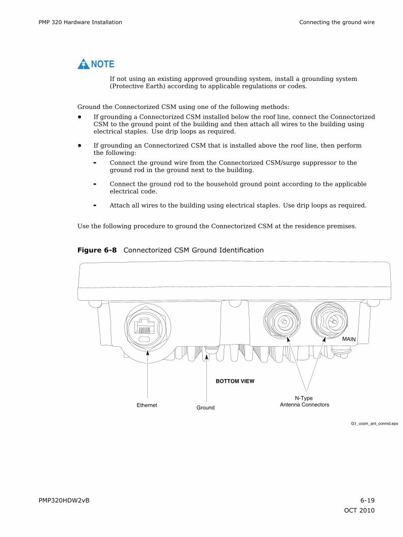
PMP 320 Hardware Installation Connecting the ground wire
NOTEIf not using an existing approved grounding system, install a grounding system(Protective Earth) according to applicable regulations or codes.
Ground the Connectorized CSM using one of the following methods:
• If grounding a Connectorized CSM installed below the roof line, connect the ConnectorizedCSM to the ground point of the building and then attach all wires to the building usingelectrical staples. Use drip loops as required.
• If grounding an Connectorized CSM that is installed above the roof line, then performthe following:
Connect the ground wire from the Connectorized CSM/surge suppressor to theground rod in the ground next to the building.
Connect the ground rod to the household ground point according to the applicableelectrical code.
Attach all wires to the building using electrical staples. Use drip loops as required.
Use the following procedure to ground the Connectorized CSM at the residence premises.
Figure 6-8 Connectorized CSM Ground Identification
G1_ccsm_ant_connid.eps
MAIN
Ethernet
BOTTOM VIEW
N-Type Antenna ConnectorsGround
PMP320HDW2vB 6-19
OCT 2010

Connecting the power supply and the Ethernet cable to the computer Chapter 6: Connectorized CSM Hardware Installation
Procedure 6-10 Grounding the Connectorized CSM
1 Wrap the AWG 10 (6mm2) copper ground wire around the ground post of theConnectorized CSM. Refer to Figure 6-8
2 Remove the cover of the 600SSD surge suppressor.
3 Wrap the AWG 10 (6mm2) copper ground wire around the ground post ofthe 600SSD.
4 Tighten the ground post locking nut.
5 Ensure the pin 4 selector in the 600SSD is set to the factory default ofisolated, not grounded.
6 If not using an existing approved grounding system, install a groundingsystem (Protective Earth) according to applicable regulations or codes.
7 Connect the ground wire from the Connectorized CSM and the 600SS toEarth Ground.
Connecting the power supply and the Ethernet cable to thecomputer
Perform the following procedure to connect the power supply and the Ethernet cables.
Procedure 6-11 Connecting the power supply
1 Plug the category 5e cord from the Connectorized CSM/surge suppressor intothe jack labeled AC Power on the Connectorized CSM Power Injector (ifthis connection is not already made).
2 Connect the protected side of the 600SSD surge suppressor cable to the Data& Power Out port of the Connectorized CSM power injector.
3 Use a standard category 5e Ethernet cable to connect the computer to thejack labeled computer on the power supply.
NOTEThe cable to the Connectorized CSM provides both the power andthe Ethernet connection. The cable is compatible with the IEEEStandard 802.3af power over Ethernet.
4 The power cord uses standard household power. Plug the power cord in theAC power source.
NOTEThe AC line cord is not provided with the hardware. Acquire theappropriate power line cord for the country where the unit isinstalled.
6-20 PMP320HDW2vB
OCT 2010

PMP 320 Hardware Installation Connecting the power supply and the Ethernet cable to the computer
Figure 6-7 illustrates the cable connection through the data line protector and into the powersupply cord.
PMP320HDW2vB 6-21
OCT 2010

Connecting the power supply and the Ethernet cable to the computer Chapter 6: Connectorized CSM Hardware Installation
6-22 PMP320HDW2vB
OCT 2010

Chapter
7
Regulatory, Legal, and Safety Notices■ ■ ■ ■ ■ ■ ■ ■ ■ ■ ■ ■ ■ ■ ■ ■ ■ ■ ■ ■ ■ ■ ■ ■ ■ ■ ■ ■ ■ ■ ■ ■ ■ ■ ■ ■ ■ ■ ■ ■ ■ ■ ■ ■ ■ ■ ■ ■ ■ ■ ■ ■ ■ ■ ■ ■ ■ ■ ■ ■ ■
■
■
■
■
PMP320HDW2vB 7-1
OCT 2010

IMPORTANT NOTE ON MODIFICATIONS Chapter 7: Regulatory, Legal, and Safety Notices
IMPORTANT NOTE ON MODIFICATIONS■ ■ ■ ■ ■ ■ ■ ■ ■ ■ ■ ■ ■ ■ ■ ■ ■ ■ ■ ■ ■ ■ ■ ■ ■ ■ ■ ■ ■ ■ ■ ■ ■ ■ ■ ■ ■ ■ ■ ■ ■ ■ ■ ■ ■ ■ ■ ■ ■ ■ ■ ■ ■ ■ ■ ■ ■ ■ ■ ■ ■
■
■
Intentional or unintentional changes or modifications to the equipment must not be made unlessunder the express consent of the party responsible for compliance. Any such modifications couldvoid the user’s authority to operate the equipment and will void the manufacturer’s warranty.
7-2 PMP320HDW2vB
OCT 2010
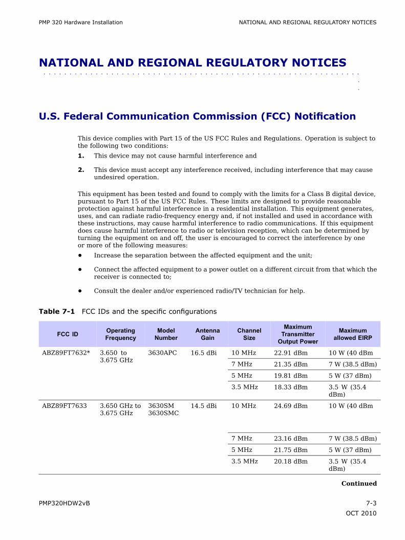
PMP 320 Hardware Installation NATIONAL AND REGIONAL REGULATORY NOTICES
NATIONAL AND REGIONAL REGULATORY NOTICES■ ■ ■ ■ ■ ■ ■ ■ ■ ■ ■ ■ ■ ■ ■ ■ ■ ■ ■ ■ ■ ■ ■ ■ ■ ■ ■ ■ ■ ■ ■ ■ ■ ■ ■ ■ ■ ■ ■ ■ ■ ■ ■ ■ ■ ■ ■ ■ ■ ■ ■ ■ ■ ■ ■ ■ ■ ■ ■ ■ ■
■
■
U.S. Federal Communication Commission (FCC) Notification
This device complies with Part 15 of the US FCC Rules and Regulations. Operation is subject tothe following two conditions:
1. This device may not cause harmful interference and
2. This device must accept any interference received, including interference that may causeundesired operation.
This equipment has been tested and found to comply with the limits for a Class B digital device,pursuant to Part 15 of the US FCC Rules. These limits are designed to provide reasonableprotection against harmful interference in a residential installation. This equipment generates,uses, and can radiate radio-frequency energy and, if not installed and used in accordance withthese instructions, may cause harmful interference to radio communications. If this equipmentdoes cause harmful interference to radio or television reception, which can be determined byturning the equipment on and off, the user is encouraged to correct the interference by oneor more of the following measures:
• Increase the separation between the affected equipment and the unit;
• Connect the affected equipment to a power outlet on a different circuit from that which thereceiver is connected to;
• Consult the dealer and/or experienced radio/TV technician for help.
Table 7-1 FCC IDs and the specific configurations
FCC ID OperatingFrequency
ModelNumber
AntennaGain
ChannelSize
MaximumTransmitterOutput Power
Maximumallowed EIRP
10 MHz 22.91 dBm 10 W (40 dBm
7 MHz 21.35 dBm 7 W (38.5 dBm)
5 MHz 19.81 dBm 5 W (37 dBm)
ABZ89FT7632* 3.650 to3.675 GHz
3630APC 16.5 dBi
3.5 MHz 18.33 dBm 3.5 W (35.4dBm)
10 MHz 24.69 dBm 10 W (40 dBm
7 MHz 23.16 dBm 7 W (38.5 dBm)
5 MHz 21.75 dBm 5 W (37 dBm)
ABZ89FT7633 3.650 GHz to3.675 GHz
3630SM3630SMC
14.5 dBi
3.5 MHz 20.18 dBm 3.5 W (35.4dBm)
Continued
PMP320HDW2vB 7-3
OCT 2010

Industry Canada Notification Chapter 7: Regulatory, Legal, and Safety Notices
Table 7-1 FCC IDs and the specific configurations (Continued)
FCC ID OperatingFrequency
ModelNumber
AntennaGain
ChannelSize
MaximumTransmitterOutput Power
Maximumallowed EIRP
* For 3630 APC, the maximum transmitter power reflects two transmitters. The maximum TX power settingfor the Access Point is 10 MHz channel – 19.91 dBm, 7 MHz channel – 18.35 dBm, 5 MHz channel –16.85 dBm, and 3.5 MHz channel – 15.33 dBm.
Industry Canada Notification
This device is approved for use in Canada in the licensed frequencies from 3.450 GHz to 3.700GHz. It is undergoing Industry Canada approval for use in the 3.65 GHz band, and may not beused in that band until Industry Canada approval is granted.
Operation is subject to the following two conditions:
• This device may not cause harmful interference and
• This device must accept any interference received, including interference that may causeundesired operation.
This equipment has been tested and found to comply with the limits for a Class B digital device.These limits are designed to provide reasonable protection against harmful interference ina residential installation. This equipment generates, uses, and can radiate radio-frequencyenergy and if not installed and used in accordance with these instructions, may cause harmfulinterference to radio communications. If this equipment does cause harmful interference toradio or television reception, which can be determined by turning the equipment on and off, theuser is encouraged to correct the interference by one or more of the following measures:
• Increase the separation between the affected equipment and the unit;
• Connect the affected equipment to a power outlet on a different circuit from that which thereceiver is connected to;
• Consult the dealer and/or experienced radio/TV technician for help.
To reduce potential radio interference to other users, the antenna type and its gain should bechosen so its Equivalent Isotropic Radiated Power (EIRP) is not more than that permitted forsuccessful communication.
The following tables provide a guideline for setting the PMP320 access point transmit powerbased on the operator’s selection of channel bandwidth, channel frequency and whether they areoperating in a low or high population area. Low population areas are defined by Industry Canadaas those Tier 4 areas that are subject to the minimum license fee, as identified in CPC-2-1-26.(http://www.ic.gc.ca/eic/site/smt-gst.nsf/eng/h_sf01627.html; click on the link for tier 4 areas)
The tables are used by selecting the population density (low or high), channel bandwidth (3.5/ 5.0 / 7.0 / 10.0), and channel (see examples of low/mid/high) to determine the maximumtransmit power setting allowed.
The certification numbers are 109W-3630APC and 109W-3630SM for the AP and the SMrespectively. Refer to the following URL to see the official Radio Equipment List (REL) fromCanada: http://www.ic.gc.ca/app/sitt/reltel/srch/nwRdSrch.do?lang=eng(Search company name= Motorola; model # = 3630 or 3530 )
7-4 PMP320HDW2vB
OCT 2010

PMP 320 Hardware Installation Industry Canada Notification
Table 7-2 Industry Canada Certification Numbers and the specific configuration
CERT ID OperatingFrequency
ModelNumber Antenna Gain
ChannelSize 3.5,5, 7, and10 MHz
MaximumAllowedEIRP
MaximumTransmitterOutput Power
109 W– 3530APC
3.450 GHzto 3.600GHz
3530 APC 16.5 dBiconnectorized
any NA 28 dBm (630mW)
109 W– 3630APC
3.600 GHzto 3.650GHz
3630 APC 17 dBiconnectorized
any NA 28 dBm (630mW)
109W– 3530SM
3.450 GHzto 3.600GHz
3530 SM
109W– 3630SM
3.600 GHzto 36.50GHz
3630 SM14.5 dBi NA NA
27 dBm (500mW)
109W-3530SMC3.450 GHzto 3.600GHz
3530SMC
109W-3630SMC3.600 GHzto 36.50GHz
3630SMCNA** NA NA
27 dBm (500mW)
* see Table 7-7 for specific guidelines for the AP transmit power.
** refer to for Certified Antenna Information
Table 7-3 Certified Antenna Information
Model Antenna Type Gain (dBi) Connection
MA-W036–10N OMNI Directional 9.5 dBi
MA-WA36–DP21 Dual Polarization 22.0 dBiN-type
Table 7-4 3.600 – 3.650 MHz
3.5 MHz 5 MHz 7 MHz 10 MHzChannels
FREQ (MHz) Power(dBm)
FREQ(MHz)
Power(dBm)
FREQ(MHz)
Power(dBm)
FREQ(MHz)
Power(dBm)
Low 3608.75 25 3608.75 25 3608.75 25 3608.75 25
Middle 3625 25 3625 25 3625 25 3625 25
Upper 3642.5 25 3642.5 25 3642.5 25 3642.5 25
PMP320HDW2vB 7-5
OCT 2010

European Union Notification Chapter 7: Regulatory, Legal, and Safety Notices
Table 7-5 3.650 – 3.700 MHz: Low Population Area*
3.5 MHz 5 MHz 7 MHz 10 MHzChannels
FREQ (MHz) Power(dBm)
FREQ(MHz)
Power(dBm)
FREQ(MHz)
Power(dBm)
FREQ(MHz)
Power(dBm)
Low 3655.5 20 3656 20 3658 20 3660 20
Middle 3675 25 3675 25 3675 25 3675 25
Upper 3695 20 3693 20 3692.5 20 3692 20
* Up to 25 dBm Tx power and able to use full 50 MHz of spectrum.
Table 7-6 3.600 – 3.650 MHz: High Population Area*
3.5 MHz 5 MHz 7 MHz 10 MHzChannels
FREQ (MHz) Power(dBm)
FREQ(MHz)
Power(dBm)
FREQ(MHz)
Power(dBm)
FREQ(MHz)
Power(dBm)
Low 3654.5 16 3656 17 3658 18 3657 20
Middle 3662.5 16 3662.5 17 3662.5 18 3662.5 20
Upper 3670 16 3669.5 17 3667.5 18 3668 20
* Up to 20 dBm Tx power and limited to lower 25 MHz of spectrum.
European Union Notification
The relevant Declaration of Conformity can be found at
http://motorola.wirelessbroadbandsupport.com/doc.php
Equipment Disposal
Please do not dispose of Electronic and Electric Equipment or Electronic and ElectricAccessories with your household waste. In some countries or regions, collection systemshave been set up to handle waste of electrical and electronic equipment. In European Unioncountries, please contact your local equipment supplier representative or service center forinformation about the waste collection system in your country.
7-6 PMP320HDW2vB
OCT 2010

PMP 320 Hardware Installation EU Declaration of Conformity for RoHS Compliance
EU Declaration of Conformity for RoHS Compliance
Motorola hereby, declares that these Motorola products are in compliance with the essentialrequirements and other relevant provisions of Directive 2002/95/EC, Restriction of the use ofcertain Hazardous Substances (RoHS) in electrical and electronic equipment.
The relevant Declaration of Conformity can be found athttp://motorola.wirelessbroadbandsupport.com/doc.php.
Labeling and Disclosure Table for China
The People’s Republic of China requires that Motorola’s products comply with ChinaManagementMethods (CMM) environmental regulations. (China Management Methods refers to theregulation Management Methods for Controlling Pollution by Electronic Information Products.)Two items are used to demonstrate compliance - the label, and the disclosure table Table 6 3Disclosure table.
The label is placed in a customer visible position on the product.
• Logo 1 means that the product contains no substances in excess of the maximumconcentration value for materials identified in the China Management Methods regulation.
• Logo 2 means that the product may contain substances in excess of the maximumconcentration value for materials identified in the China Management Methods regulation,and has an Environmental Friendly Use Period (EFUP) in years, fifty years in the exampleshown.
Logo 1 Logo 2
The Environmental Friendly Use Period (EFUP) is the period (in years) during which the Toxicand Hazardous Substances (T&HS) contained in the Electronic Information Product (EIP)will not leak or mutate causing environmental pollution or bodily injury from the use of theEIP. The EFUP indicated by the Logo 2 label applies to a product and all its parts. Certainfield-replaceable parts, such as battery modules, can have a different EFUP and are markedseparately.
The Disclosure table is intended to communicate compliance with only China requirements;it is not intended to communicate compliance with EU RoHS or any other environmentalrequirements.
PMP320HDW2vB 7-7
OCT 2010

Labeling and Disclosure Table for China Chapter 7: Regulatory, Legal, and Safety Notices
Figure 7-1 Disclosure Table
7-8 PMP320HDW2vB
OCT 2010

PMP 320 Hardware Installation RF EXPOSURE SEPARATION DISTANCES
RF EXPOSURE SEPARATION DISTANCES■ ■ ■ ■ ■ ■ ■ ■ ■ ■ ■ ■ ■ ■ ■ ■ ■ ■ ■ ■ ■ ■ ■ ■ ■ ■ ■ ■ ■ ■ ■ ■ ■ ■ ■ ■ ■ ■ ■ ■ ■ ■ ■ ■ ■ ■ ■ ■ ■ ■ ■ ■ ■ ■ ■ ■ ■ ■ ■ ■ ■
■
■
To protect from overexposure to RF energy, an AP must be installed to provide a separationdistance of at least 50 cm ( ~20 in) from all persons In addition, do not collocate within 20 cm(4 in) of any other antenna or transmitter.
To protect from overexposure to RF energy, an SM must be installed to provide a separationdistance of at least 50 cm ( ~20 in) from all persons and must not be collocated or operatingwith any other antenna or transmitter.
The following section and table provide details and discussion on the separate distancecalculations.
Details of Exposure Separation Distances Calculations andPower Compliance Margins
Limits and guidelines for RF exposure come from:
• US FCC limits for the general population. See the FCC web site at http://www.fcc.gov, andthe policies, guidelines, and requirements in Part 1 of Title 47 of the Code of FederalRegulations, as well as the guidelines and suggestions for evaluating compliance in FCCOET Bulletin 65.
• Health Canada limits for the general population. See the Health Canada web site athttp://www.hc-sc.gc.ca/rpb and Safety Code 6.
• ICNIRP (International Commission on Non-Ionizing Radiation Protection) guidelines forthe general public. See the ICNIRP web site at http://www.icnirp.de/ and Guidelines forLimiting Exposure to Time-Varying Electric, Magnetic, and Electromagnetic Fields.
The applicable power density exposure limits from the documents referenced above is 10 W/m2.
Peak power density in the far field of a radio frequency point source is calculated as:
Figure 7-2 Peak power density calculation
Table 7-7 shows calculated minimum separation distances d, recommended distances andresulting power compliance margins for each frequency band and antenna combination.
PMP320HDW2vB 7-9
OCT 2010

Details of Exposure Separation Distances Calculations and Power Compliance Margins Chapter 7:Regulatory, Legal, and Safety Notices
Table 7-7 Calculated exposure distances and power compliance margins
VariableBand Unit
P G SDistance d(calculated)
RecommendedSeparationDistance
PowerCompliance
Margin
3.3 GHz to 3.8GHz
AP 0.5 W (27dBm)
44.7(16.5 dB)
10W/m²
42 cm 52 cm (~20 in) 1.5
3.650 to 3.675GHz (FCC PowerLimits)
AP 0.195 W(22.91dBm)
44.7(16.5 dB)
10W/m²
26.4 cm 52 cm (~20 in) 3.9
3.3 GHz to 3.8GHz
SM(CSM)
0.5 W(27dBm)
28.2(14.5 dB)
10W/m²
33 cm 50 cm (~20 in) 2.23
These are conservative distances:
• They are along the beam direction (the direction of greatest energy). Exposure to the sidesand back of the module is significantly less.
• In the case of collocated APs, they assume all APs are oriented in the same direction,which is a worst-case calculation.
• They meet or exceed sustained exposure limits for the general population (not justshort-term occupational exposure limits).
• The calculated compliance distance d is overestimated because the far-field equationmodels the antenna(s) as a point source and neglects the physical dimension of theantenna(s).
Table 7-8 Exposure separation distances
Module Type Separation Distance from Persons
PMP 320 AP At least 50 cm (approximately 20inches)
7-10 PMP320HDW2vB
OCT 2010

PMP 320 Hardware Installation Software License Terms and Conditions
Software License Terms and Conditions■ ■ ■ ■ ■ ■ ■ ■ ■ ■ ■ ■ ■ ■ ■ ■ ■ ■ ■ ■ ■ ■ ■ ■ ■ ■ ■ ■ ■ ■ ■ ■ ■ ■ ■ ■ ■ ■ ■ ■ ■ ■ ■ ■ ■ ■ ■ ■ ■ ■ ■ ■ ■ ■ ■ ■ ■ ■ ■ ■ ■
■
■
ONLY OPEN THE PACKAGE, OR USE THE SOFTWARE AND RELATED PRODUCT IF YOUACCEPT THE TERMS OF THIS LICENSE. BY BREAKING THE SEAL ON THIS DISK KIT /CDROM, OR IF YOU USE THE SOFTWARE OR RELATED PRODUCT, YOU ACCEPT THE TERMSOF THIS LICENSE AGREEMENT. IF YOU DO NOT AGREE TO THESE TERMS, DO NOT USETHE SOFTWARE OR RELATED PRODUCT; INSTEAD, RETURN THE SOFTWARE TO PLACE OFPURCHASE FOR A FULL REFUND. THE FOLLOWING AGREEMENT IS A LEGAL AGREEMENTBETWEEN YOU (EITHER AN INDIVIDUAL OR ENTITY), AND MOTOROLA, INC. (FOR ITSELFAND ITS LICENSORS). THE RIGHT TO USE THIS PRODUCT IS LICENSED ONLY ON THECONDITION THAT YOU AGREE TO THE FOLLOWING TERMS.
Now, therefore, in consideration of the promises and mutual obligations contained herein, andfor other good and valuable consideration, the receipt and sufficiency of which are herebymutually acknowledged, you and Motorola agree as follows:
Grant of License. Subject to the following terms and conditions, Motorola, Inc., grants to youa personal, revocable, non-assignable, non-transferable, non-exclusive and limited license touse on a single piece of equipment only one copy of the software contained on this disk (whichmay have been pre-loaded on the equipment)(Software). You may make two copies of theSoftware, but only for backup, archival, or disaster recovery purposes. On any copy you makeof the Software, you must reproduce and include the copyright and other proprietary rightsnotice contained on the copy we have furnished you of the Software. Ownership. Motorola (orits supplier) retains all title, ownership and intellectual property rights to the Software andany copies, including translations, compilations, derivative works (including images) partialcopies and portions of updated works. The Software is Motorola’s (or its supplier's) confidentialproprietary information. This Software License Agreement does not convey to you any interestin or to the Software, but only a limited right of use. You agree not to disclose it or makeit available to anyone without Motorola’s written authorization. You will exercise no lessthan reasonable care to protect the Software from unauthorized disclosure. You agree not todisassemble, decompile or reverse engineer, or create derivative works of the Software, exceptand only to the extent that such activity is expressly permitted by applicable law.
Termination. This License is effective until terminated. This License will terminate immediatelywithout notice from Motorola or judicial resolution if you fail to comply with any provision ofthis License. Upon such termination you must destroy the Software, all accompanying writtenmaterials and all copies thereof, and the sections entitled Limited Warranty, Limitation ofRemedies and Damages, and General will survive any termination.
Limited Warranty. Motorola warrants for a period of ninety (90) days from Motorola’s orits customer’s shipment of the Software to you that (i) the disk(s) on which the Software isrecorded will be free from defects in materials and workmanship under normal use and (ii) theSoftware, under normal use, will perform substantially in accordance with Motorola’s publishedspecifications for that release level of the Software. The written materials are provided "AS IS"and without warranty of any kind. Motorola's entire liability and your sole and exclusive remedyfor any breach of the foregoing limited warranty will be, at Motorola's option, replacement of thedisk(s), provision of downloadable patch or replacement code, or refund of the unused portion ofyour bargained for contractual benefit up to the amount paid for this Software License.
PMP320HDW2vB 7-11
OCT 2010

Software License Terms and Conditions Chapter 7: Regulatory, Legal, and Safety Notices
THIS LIMITED WARRANTY IS THE ONLY WARRANTY PROVIDED BY MOTOROLA, ANDMOTOROLA AND ITS LICENSORS EXPRESSLY DISCLAIM ALL OTHER WARRANTIES, EITHEREXPRESS OF IMPLIED, INCLUDING BUT NOT LIMITED TO IMPLIED WARRANTIES OFMERCHANTABILITY AND FITNESS FOR A PARTICULAR PURPOSE AND NONINFRINGEMENT.MOTOROLA DOES NOT WARRANT THAT THE OPERATION OF THE SOFTWARE WILL BEUNINTERRUPTED OR ERRORFREE, OR THAT DEFECTS IN THE SOFTWARE WILL BECORRECTED. NO ORAL OR WRITTEN REPRESENTATIONS MADE BY MOTOROLA OR ANAGENT THEREOF SHALL CREATE A WARRANTY OR IN ANY WAY INCREASE THE SCOPEOF THIS WARRANTY. MOTOROLA DOES NOT WARRANT ANY SOFTWARE THAT HASBEEN OPERATED IN EXCESS OF SPECIFICATIONS, DAMAGED, MISUSED, NEGLECTED,OR IMPROPERLY INSTALLED. BECAUSE SOME JURISDICTIONS DO NOT ALLOW THEEXCLUSION OR LIMITATION OF IMPLIED WARRANTIES, THE ABOVE LIMITATIONS MAYNOT APPLY TO YOU.
Limitation of Remedies and Damages. Regardless of whether any remedy set forth hereinfails of its essential purpose, IN NO EVENT SHALL MOTOROLA OR ANY OF THE LICENSORS,DIRECTORS, OFFICERS, EMPLOYEES OR AFFILIATES OF THE FOREGOING BE LIABLE TOYOU FOR ANY CONSEQUENTIAL, INCIDENTAL, INDIRECT, SPECIAL OR SIMILAR DAMAGESWHATSOEVER (including, without limitation, damages for loss of business profits, businessinterruption, loss of business information and the like), whether foreseeable or unforeseeable,arising out of the use or inability to use the Software or accompanying written materials,regardless of the basis of the claim and even if Motorola or a Motorola representative hasbeen advised of the possibility of such damage. Motorola's liability to you for direct damagesfor any cause whatsoever, regardless of the basis of the form of the action, will be limited tothe price paid for the Software that caused the damages. THIS LIMITATION WILL NOT APPLYIN CASE OF PERSONAL INJURY ONLY WHERE AND TO THE EXTENT THAT APPLICABLELAW REQUIRES SUCH LIABILITY. BECAUSE SOME JURISDICTIONS DO NOT ALLOWTHE EXCLUSION OR LIMITATION OF LIABILITY FOR CONSEQUENTIAL OR INCIDENTALDAMAGES, THE ABOVE LIMITATION MAY NOT APPLY TO YOU.
Maintenance and Support. Motorola shall not be responsible for maintenance or support ofthe software. By accepting the license granted under this agreement, you agree that Motorolawill be under no obligation to provide any support, maintenance or service in connection withthe Software or any application developed by you. Any maintenance and support of the RelatedProduct will be provided under the terms of the agreement for the Related Product.
Transfer. In the case of software designed to operate on Motorola equipment, you may nottransfer the Software to another party except: (1) if you are an end-user, when you aretransferring the Software together with the Motorola equipment on which it operates; or 2) ifyou are a Motorola licensed distributor, when you are transferring the Software either togetherwith such Motorola equipment or are transferring the Software as a licensed duly paid forupgrade, update, patch, new release, enhancement or replacement of a prior version of theSoftware. If you are a Motorola licensed distributor, when you are transferring the Software aspermitted herein, you agree to transfer the Software with a license agreement having terms andconditions no less restrictive than those contained herein. You may transfer all other Software,not otherwise having an agreed restriction on transfer, to another party. However, all suchtransfers of Software are strictly subject to the conditions precedent that the other party agreesto accept the terms and conditions of this License, and you destroy any copy of the Software youdo not transfer to that party. You may not sublicense or otherwise transfer, rent or lease theSoftware without our written consent. You may not transfer the Software in violation of anylaws, regulations, export controls or economic sanctions imposed by the US Government.
Right to Audit. Motorola shall have the right to audit annually, upon reasonable advancenotice and during normal business hours, your records and accounts to determine compliancewith the terms of this Agreement.
Export Controls. You specifically acknowledge that the software may be subject to UnitedStates and other country export control laws. You shall comply strictly with all requirements ofall applicable export control laws and regulations with respect to all such software and materials.
7-12 PMP320HDW2vB
OCT 2010

PMP 320 Hardware Installation Software License Terms and Conditions
US Government Users. If you are a US Government user, then the Software is providedwith "RESTRICTED RIGHTS" as set forth in subparagraphs (c)(1) and (2) of the CommercialComputer Software-Restricted Rights clause at FAR 52 227-19 or subparagraph (c)(1)(ii) of theRights in Technical Data and Computer Software clause at DFARS 252.227-7013, as applicable.
Disputes. You and Motorola hereby agree that any dispute, controversy or claim, except for anydispute, controversy or claim involving intellectual property, prior to initiation of any formallegal process, will be submitted for non-binding mediation, prior to initiation of any formal legalprocess. Cost of mediation will be shared equally. Nothing in this Section will prevent eitherparty from resorting to judicial proceedings, if (i) good faith efforts to resolve the disputeunder these procedures have been unsuccessful, (ii) the dispute, claim or controversy involvesintellectual property, or (iii) interim relief from a court is necessary to prevent serious andirreparable injury to that party or to others.
General. Illinois law governs this license. The terms of this license are supplemental to anywritten agreement executed by both parties regarding this subject and the Software Motorola isto license you under it, and supersedes all previous oral or written communications between usregarding the subject except for such executed agreement. It may not be modified or waivedexcept in writing and signed by an officer or other authorized representative of each party. Ifany provision is held invalid, all other provisions shall remain valid, unless such invalidity wouldfrustrate the purpose of our agreement. The failure of either party to enforce any rights grantedhereunder or to take action against the other party in the event of any breach hereunder shallnot be deemed a waiver by that party as to subsequent enforcement of rights or subsequentaction in the event of future breaches.
PMP320HDW2vB 7-13
OCT 2010

Hardware Warranty in US Chapter 7: Regulatory, Legal, and Safety Notices
Hardware Warranty in US■ ■ ■ ■ ■ ■ ■ ■ ■ ■ ■ ■ ■ ■ ■ ■ ■ ■ ■ ■ ■ ■ ■ ■ ■ ■ ■ ■ ■ ■ ■ ■ ■ ■ ■ ■ ■ ■ ■ ■ ■ ■ ■ ■ ■ ■ ■ ■ ■ ■ ■ ■ ■ ■ ■ ■ ■ ■ ■ ■ ■
■
■
Motorola US offers a warranty covering a period of 1 year from the date of purchase by thecustomer. If a product is found defective during the warranty period, Motorola will repair orreplace the product with the same or a similar model, which may be a reconditioned unit,without charge for parts or labor.
7-14 PMP320HDW2vB
OCT 2010

PMP 320 Hardware Installation LIMIT OF LIABILITY
LIMIT OF LIABILITY■ ■ ■ ■ ■ ■ ■ ■ ■ ■ ■ ■ ■ ■ ■ ■ ■ ■ ■ ■ ■ ■ ■ ■ ■ ■ ■ ■ ■ ■ ■ ■ ■ ■ ■ ■ ■ ■ ■ ■ ■ ■ ■ ■ ■ ■ ■ ■ ■ ■ ■ ■ ■ ■ ■ ■ ■ ■ ■ ■ ■
■
■
IN NO EVENT SHALL MOTOROLA BE LIABLE TO YOU OR ANY OTHER PARTY FOR ANYDIRECT, INDIRECT, GENERAL, SPECIAL, INCIDENTAL, CONSEQUENTIAL, EXEMPLARYOR OTHER DAMAGE ARISING OUT OF THE USE OR INABILITY TO USE THE PRODUCT(INCLUDING, WITHOUT LIMITATION, DAMAGES FOR LOSS OF BUSINESS PROFITS,BUSINESS INTERRUPTION, LOSS OF BUSINESS INFORMATION OR ANY OTHER PECUNIARYLOSS, OR FROM ANY BREACH OF WARRANTY, EVEN IF MOTOROLA HAS BEEN ADVISED OFTHE POSSIBILITY OF SUCH DAMAGES. (Some states do not allow the exclusion or limitationof incidental or consequential damages, so the above exclusion or limitation may not apply toyou.) IN NO CASE SHALL MOTOROLA’S LIABILITY EXCEED THE AMOUNT YOU PAID FORTHE PRODUCT.
PMP320HDW2vB 7-15
OCT 2010


![[A2DP] [AVRCP] - JVC...Motorola Atrix — Motorola Atrix 2 N/A N/A NG Motorola BACKFLIP ME600 —— ——NG Motorola DEFY MB525 — Motorola Droid 2 (Milestone 2) —— Motorola](https://static.fdocuments.net/doc/165x107/5fa61ea866868c7082174373/a2dp-avrcp-jvc-motorola-atrix-a-motorola-atrix-2-na-na-ng-motorola.jpg)

