PM210 Modbus Reference-2.6 - daeinstrument.com Modbus Reference-2.6.1e… · The PM210 communicates...
26
DAE Instrument Corp. PM210 v312–11 Multi-Function Panel Meter Modbus Reference Revision 2.6.1e Updated 2015/1/22 Prepared By: David Ling Firmware: v312
Transcript of PM210 Modbus Reference-2.6 - daeinstrument.com Modbus Reference-2.6.1e… · The PM210 communicates...
DAE Instrument Corp.
PM210 v312–11
Multi-Function Panel Meter
Modbus Reference
Revision 2.6.1eUpdated 2015/1/22
Prepared By: David Ling
Firmware: v312
Table of ContentsGeneral Information! 3Register Tables! 4
Real Time Data (One Word Sized)! 4
Real Time Data (Two Word Sized)! 5
Utility Energy Data! 6
Generator Energy Data! 7
Setup Data! 8
DO Control! 9
Examples! 10Read Phase Voltage! 10
Read Phase Current! 10
Read Power! 11
Read Frequency! 11
Read Power Factor! 12
Read Total Active Energy (kWh)! 12
Write Total kWh! 13
Read DO Status! 13
Control DO! 14
Read Phase/Wire! 15
Read BD15 (15 minute block demand)! 15
Read Device Address! 16
Write Device Address! 17
Read Baud Rate! 18
Write Baud Rate! 18
Read PT Ratio! 19
Write PT Ratio! 19
PM210 Modbus Reference 2.6.1e! 1/25
Read CT Ratio! 20
Write CT Ratio! 20
Read Standard/Dedicated CT! 21
Write Standard/Dedicated CT! 21
Read Temperature! 22
Read Firmware Version! 22
CRC Computation! 23Definition! 23
Usage! 23
Notes on Modscan! 24Additional Resources! 25
PM210 Modbus Reference 2.6.1e! 2/25
General Information
General InformationThe PM210 communicates using the Modbus/RTU protocol. The communications interface is RS485. The default baud rate is 9600. The data format is 8 bits, no parity, 1 stop bit. The default address of the PM210 can either be zero, one or the same as the last 2 digits of the serial number, except 00 which resolves to 100. The actual device address can be found through the front panel by entering the settings mode.
All numerical data is in integer form and must be scaled by multiplying/dividing with its indicated unit to get the final data value.
Reading is done through function code 3. Most writing is done using function code 16. All numerical values are in decimal unless otherwise specified or appended with an ʻhʼ, in which case the data is in hexadecimal. Control is done using function code 5.
The PM210 uses the address 255 instead of zero as the broadcast address.
The default address is the serial number last 2 digits or 100 when it is 00. It is possible that the defaults have been changed from the original factory settings. To find out the address and baud rate, enter the settings mode through the front panel controls. To find out the same information through Modbus, query using the broadcast address 255, but make sure that only the given PM210 is connected to the host PC, no other devices must be on the same bus network.
When a command is in error, the PM210 will not respond and simply allow the host PC doing the reading to time out. The PM210 should have a maximum latency of 300 milliseconds, this is the guaranteed time in which the PM210 should respond, if this time is exceeded, the host PC should issue a time out.
A command is in error in any of these conditions:
1. The function code is not supported.
2. The data is malformed or out of range.
3. The CRC is wrong.
This version of the Modbus registers apply to PM210 with versions 312 and up. Note especially the accumulated energy registers at locations 48~51, these are writable in this version, but in older versions, it may be writable only at locations 86~87 and 94~95.
PM210 Modbus Reference 2.6.1e! 3/25
Register Tables
Register Tables
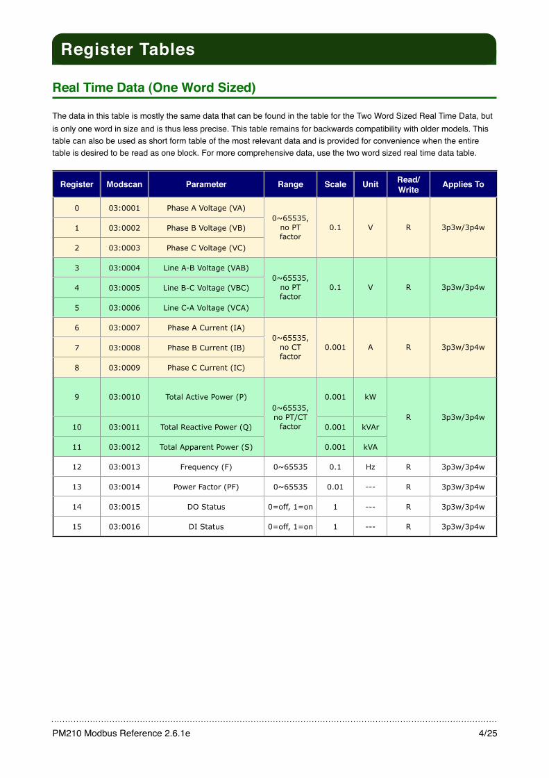
Real Time Data (One Word Sized)
The data in this table is mostly the same data that can be found in the table for the Two Word Sized Real Time Data, but is only one word in size and is thus less precise. This table remains for backwards compatibility with older models. This table can also be used as short form table of the most relevant data and is provided for convenience when the entire table is desired to be read as one block. For more comprehensive data, use the two word sized real time data table.
Register Modscan Parameter Range Scale Unit Read/Write Applies To
0 03:0001 Phase A Voltage (VA)0~65535,
no PT factor
0.1 V R 3p3w/3p4w1 03:0002 Phase B Voltage (VB)0~65535,
no PT factor
0.1 V R 3p3w/3p4w
2 03:0003 Phase C Voltage (VC)
0~65535, no PT factor
0.1 V R 3p3w/3p4w
3 03:0004 Line A-B Voltage (VAB)0~65535,
no PT factor
0.1 V R 3p3w/3p4w4 03:0005 Line B-C Voltage (VBC)0~65535,
no PT factor
0.1 V R 3p3w/3p4w
5 03:0006 Line C-A Voltage (VCA)
0~65535, no PT factor
0.1 V R 3p3w/3p4w
6 03:0007 Phase A Current (IA)0~65535,
no CT factor
0.001 A R 3p3w/3p4w7 03:0008 Phase B Current (IB)0~65535,
no CT factor
0.001 A R 3p3w/3p4w
8 03:0009 Phase C Current (IC)
0~65535, no CT factor
0.001 A R 3p3w/3p4w
9 03:0010 Total Active Power (P)0~65535, no PT/CT
factor
0.001 kW
R 3p3w/3p4w10 03:0011 Total Reactive Power (Q)
0~65535, no PT/CT
factor 0.001 kVArR 3p3w/3p4w
11 03:0012 Total Apparent Power (S)
0~65535, no PT/CT
factor
0.001 kVA
R 3p3w/3p4w
12 03:0013 Frequency (F) 0~65535 0.1 Hz R 3p3w/3p4w
13 03:0014 Power Factor (PF) 0~65535 0.01 --- R 3p3w/3p4w
14 03:0015 DO Status 0=off, 1=on 1 --- R 3p3w/3p4w
15 03:0016 DI Status 0=off, 1=on 1 --- R 3p3w/3p4w
PM210 Modbus Reference 2.6.1e! 4/25
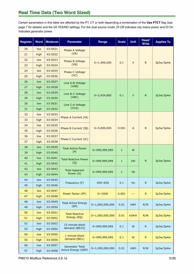
Real Time Data (Two Word Sized)
Certain parameters in this table are affected by the PT, CT or both depending a combination of the Use PTCT flag (see page 7 for details) and the 5A YES/NO settings. For the dual source mode, DI Off indicates city mains power and DI On indicates generator power.
Register Word Modscan Parameter Range Scale Unit Read/Write Applies To
20 low 03:0021 Phase A Voltage (VA)
0~1,400,000 0.1 V R 3p3w/3p4w
21 high 03:0022Phase A Voltage
(VA)
0~1,400,000 0.1 V R 3p3w/3p4w22 low 03:0023 Phase B Voltage
(VB)0~1,400,000 0.1 V R 3p3w/3p4w
23 high 03:0024Phase B Voltage
(VB)0~1,400,000 0.1 V R 3p3w/3p4w
24 low 03:0025 Phase C Voltage (VC)
0~1,400,000 0.1 V R 3p3w/3p4w
25 high 03:0026Phase C Voltage
(VC)
0~1,400,000 0.1 V R 3p3w/3p4w
26 low 03:0027 Line A-B Voltage (VAB)
0~2,424,800 0.1 V R 3p3w/3p4w
27 high 03:0028Line A-B Voltage
(VAB)
0~2,424,800 0.1 V R 3p3w/3p4w28 low 03:0029 Line B-C Voltage
(VBC)0~2,424,800 0.1 V R 3p3w/3p4w
29 high 03:0030Line B-C Voltage
(VBC)0~2,424,800 0.1 V R 3p3w/3p4w
30 low 03:0031 Line C-A Voltage (VCA)
0~2,424,800 0.1 V R 3p3w/3p4w
31 high 03:0032Line C-A Voltage
(VCA)
0~2,424,800 0.1 V R 3p3w/3p4w
32 low 03:0033Phase A Current (IA)
0~5,000,000 0.001 A R 3p3w/3p4w
33 high 03:0034Phase A Current (IA)
0~5,000,000 0.001 A R 3p3w/3p4w34 low 03:0035
Phase B Current (IB) 0~5,000,000 0.001 A R 3p3w/3p4w35 high 03:0036
Phase B Current (IB) 0~5,000,000 0.001 A R 3p3w/3p4w
36 low 03:0037Phase C Current (IC)
0~5,000,000 0.001 A R 3p3w/3p4w
37 high 03:0038Phase C Current (IC)
0~5,000,000 0.001 A R 3p3w/3p4w
38 low 03:0039 Total Active Power (P) 0~999,999,999 1 W
R 3p3w/3p4w
39 high 03:0040Total Active Power
(P) 0~999,999,999 1 W
R 3p3w/3p4w40 low 03:0041 Total Reactive Power
(Q) 0~999,999,999 1 VAr R 3p3w/3p4w41 high 03:0042
Total Reactive Power (Q) 0~999,999,999 1 VAr R 3p3w/3p4w
42 low 03:0043 Total Apparent Power (S) 0~999,999,999 1 VA
R 3p3w/3p4w
43 high 03:0044Total Apparent
Power (S) 0~999,999,999 1 VA
R 3p3w/3p4w
44 low 03:0045Frequency (F) 450~650 0.1 Hz R 3p3w/3p4w
45 high 03:0046Frequency (F) 450~650 0.1 Hz R 3p3w/3p4w
46 low 03:0047Power Factor (PF) 0~1000 0.001 --- R 3p3w/3p4w
47 high 03:0048Power Factor (PF) 0~1000 0.001 --- R 3p3w/3p4w
48 low 03:0049 Total Active Energy (EP) 0~1,000,000,000 0.01 kWh R/W 3p3w/3p4w
49 high 03:0050Total Active Energy
(EP) 0~1,000,000,000 0.01 kWh R/W 3p3w/3p4w
50 low 03:0051 Total Reactive Energy (EQ) 0~1,000,000,000 0.01 kVArh R/W 3p3w/3p4w
51 high 03:0052Total Reactive Energy (EQ) 0~1,000,000,000 0.01 kVArh R/W 3p3w/3p4w
52 low 03:0053 15 minute block demand (BD15) 0~999,999,999 0.1 W R 3p3w/3p4w
53 high 03:005415 minute block demand (BD15) 0~999,999,999 0.1 W R 3p3w/3p4w
54 low 03:0055 1 minute block demand (BD1) 0~999,999,999 0.1 W R 3p3w/3p4w
55 high 03:00561 minute block demand (BD1) 0~999,999,999 0.1 W R 3p3w/3p4w
56 low 03:0057 Generator Total Active Energy (GEP) 0~1,000,000,000 0.01 kWh R/W 3p3w/3p4w
57 high 03:0058Generator Total
Active Energy (GEP) 0~1,000,000,000 0.01 kWh R/W 3p3w/3p4w
PM210 Modbus Reference 2.6.1e! 5/25
Register Word Modscan Parameter Range Scale Unit Read/Write Applies To
58 low 03:0059 Generator Total Reactive Energy
(GEQ)0~1,000,000,000 0.01 kVArh R/W 3p3w/3p4w
59 high 03:0060
Generator Total Reactive Energy
(GEQ)0~1,000,000,000 0.01 kVArh R/W 3p3w/3p4w
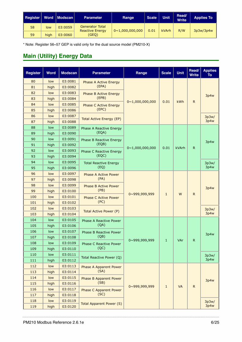
* Note: Register 56~57 GEP is valid only for the dual source model (PM210-X)
Main (Utility) Energy Data
Register Word Modscan Parameter Range Scale Unit Read/Write
Applies To
80 low 03:0081 Phase A Active Energy (EPA)
0~1,000,000,000 0.01 kWh R
3p4w
81 high 03:0082Phase A Active Energy
(EPA)
0~1,000,000,000 0.01 kWh R
3p4w82 low 03:0083 Phase B Active Energy
(EPB)0~1,000,000,000 0.01 kWh R
3p4w83 high 03:0084
Phase B Active Energy (EPB)
0~1,000,000,000 0.01 kWh R
3p4w
84 low 03:0085 Phase C Active Energy (EPC)
0~1,000,000,000 0.01 kWh R
3p4w
85 high 03:0086Phase C Active Energy
(EPC)
0~1,000,000,000 0.01 kWh R
3p4w
86 low 03:0087Total Active Energy (EP)
0~1,000,000,000 0.01 kWh R
3p3w/3p4w87 high 03:0088
Total Active Energy (EP)
0~1,000,000,000 0.01 kWh R
3p3w/3p4w
88 low 03:0089 Phase A Reactive Energy (EQA)
0~1,000,000,000 0.01 kVArh R
3p4w
89 high 03:0090Phase A Reactive Energy
(EQA)
0~1,000,000,000 0.01 kVArh R
3p4w90 low 03:0091 Phase B Reactive Energy
(EQB)0~1,000,000,000 0.01 kVArh R
3p4w91 high 03:0092
Phase B Reactive Energy (EQB)
0~1,000,000,000 0.01 kVArh R
3p4w
92 low 03:0093 Phase C Reactive Energy (EQC)
0~1,000,000,000 0.01 kVArh R
3p4w
93 high 03:0094Phase C Reactive Energy
(EQC)
0~1,000,000,000 0.01 kVArh R
3p4w
94 low 03:0095 Total Reactive Energy (EQ)
0~1,000,000,000 0.01 kVArh R
3p3w/3p4w95 high 03:0096
Total Reactive Energy (EQ)
0~1,000,000,000 0.01 kVArh R
3p3w/3p4w
96 low 03:0097 Phase A Active Power (PA)
0~999,999,999 1 W R
3p4w
97 high 03:0098Phase A Active Power
(PA)
0~999,999,999 1 W R
3p4w98 low 03:0099 Phase B Active Power
(PB)0~999,999,999 1 W R
3p4w99 high 03:0100
Phase B Active Power (PB)
0~999,999,999 1 W R
3p4w
100 low 03:0101 Phase C Active Power (PC)
0~999,999,999 1 W R
3p4w
101 high 03:0102Phase C Active Power
(PC)
0~999,999,999 1 W R
3p4w
102 low 03:0103Total Active Power (P)
0~999,999,999 1 W R
3p3w/3p4w103 high 03:0104
Total Active Power (P)
0~999,999,999 1 W R
3p3w/3p4w
104 low 03:0105 Phase A Reactive Power (QA)
0~999,999,999 1 VAr R
3p4w
105 high 03:0106Phase A Reactive Power
(QA)
0~999,999,999 1 VAr R
3p4w106 low 03:0107 Phase B Reactive Power
(QB)0~999,999,999 1 VAr R
3p4w107 high 03:0108
Phase B Reactive Power (QB)
0~999,999,999 1 VAr R
3p4w
108 low 03:0109 Phase C Reactive Power (QC)
0~999,999,999 1 VAr R
3p4w
109 high 03:0110Phase C Reactive Power
(QC)
0~999,999,999 1 VAr R
3p4w
110 low 03:0111Total Reactive Power (Q)
0~999,999,999 1 VAr R
3p3w/3p4w111 high 03:0112
Total Reactive Power (Q)
0~999,999,999 1 VAr R
3p3w/3p4w
112 low 03:0113 Phase A Apparent Power (SA)
0~999,999,999 1 VA R
3p4w
113 high 03:0114Phase A Apparent Power
(SA)
0~999,999,999 1 VA R
3p4w114 low 03:0115 Phase B Apparent Power
(SB)0~999,999,999 1 VA R
3p4w115 high 03:0116
Phase B Apparent Power (SB)
0~999,999,999 1 VA R
3p4w
116 low 03:0117 Phase C Apparent Power (SC)
0~999,999,999 1 VA R
3p4w
117 high 03:0118Phase C Apparent Power
(SC)
0~999,999,999 1 VA R
3p4w
118 low 03:0119Total Apparent Power (S)
0~999,999,999 1 VA R
3p3w/3p4w119 high 03:0120
Total Apparent Power (S)
0~999,999,999 1 VA R
3p3w/3p4w
PM210 Modbus Reference 2.6.1e! 6/25

Register Word Modscan Parameter Range Scale Unit Read/Write
Applies To
120 1 word 03:0121 Phase A Power Factor (PFA)
0~1000 0.001 --- R3p4w121 1 word 03:0122 Phase B Power Factor
(PFB)0~1000 0.001 --- R
3p4w
122 1 word 03:0123 Phase C Power Factor (PFC)
0~1000 0.001 --- R3p4w
123 1 word 03:0124 Total Power Factor (PF)
0~1000 0.001 --- R
3p3w/3p4w
Generator Energy DataThis Generator Energy Data table is valid only for the dual source model (PM210-X).
Register Word Modscan Parameter Range Scale Unit Read/Write
Applies To
144 low 03:0145 Generator Phase A Active Energy (GEPA)
0~1,000,000,000 0.01 kWh R
3p4w
145 high 03:0146Generator Phase A Active
Energy (GEPA)
0~1,000,000,000 0.01 kWh R
3p4w146 low 03:0147 Generator Phase B Active
Energy (GEPB)0~1,000,000,000 0.01 kWh R
3p4w147 high 03:0148
Generator Phase B Active Energy (GEPB)
0~1,000,000,000 0.01 kWh R
3p4w
148 low 03:0149 Generator Phase C Active Energy (GEPC)
0~1,000,000,000 0.01 kWh R
3p4w
149 high 03:0150Generator Phase C Active
Energy (GEPC)
0~1,000,000,000 0.01 kWh R
3p4w
150 low 03:0151 Generator Total Active Energy (GEP)
0~1,000,000,000 0.01 kWh R
3p3w/3p4w151 high 03:0152
Generator Total Active Energy (GEP)
0~1,000,000,000 0.01 kWh R
3p3w/3p4w
152 low 03:0153 Generator Phase A Reactive Energy (EQA)
0~1,000,000,000 0.01 kVArh R
3p4w
153 high 03:0154Generator Phase A
Reactive Energy (EQA)
0~1,000,000,000 0.01 kVArh R
3p4w154 low 03:0155 Generator Phase B
Reactive Energy (EQB)0~1,000,000,000 0.01 kVArh R
3p4w155 high 03:0156
Generator Phase B Reactive Energy (EQB)
0~1,000,000,000 0.01 kVArh R
3p4w
156 low 03:0157 Generator Phase C Reactive Energy (EQC)
0~1,000,000,000 0.01 kVArh R
3p4w
157 high 03:0158Generator Phase C
Reactive Energy (EQC)
0~1,000,000,000 0.01 kVArh R
3p4w
158 low 03:0159 Generator Total Reactive Energy (EQ)
0~1,000,000,000 0.01 kVArh R
3p3w/3p4w159 high 03:0160
Generator Total Reactive Energy (EQ)
0~1,000,000,000 0.01 kVArh R
3p3w/3p4w
Notes:• BD15 = 15 minute sliding block demand, data updated every 3 seconds, this is available only in the • BD1 = 1 minute sliding block demand, data updated every 3 seconds• Registers 56 to 59 and 144 to 159 are the second set of energy accumulator registers that is available only for the dual
source model (PM210-X-STD). This set is used when the generator power is active. The data read from registers 56~57 are the same as 150~151, while registers 58~59 are the same as 158~159, the difference being that only the registers 56~59 are writable.
PM210 Modbus Reference 2.6.1e! 7/25

Setup Data
Register Modscan Parameter Range Scale Unit Read/Write
128 03:0129 Phase/Wire: 3p3w or 3p4w 0=3p4w, 1=3p3w-2CT, 2=1p3w, 3=3p3w-3CT 1 --- R
129 03:0130 --- --- --- --- ---
130 03:0131 --- --- --- --- ---
131 03:0132 Device Address 1~254default = 1 1 --- R/W
132 03:0133 Baud Rate0=1200, 1=2400, 2=4800,
3=9600default = 9600
1 bauds R/W
133 03:0134 PT ratio 1~40,000default = 1.00 0.01 --- R/W
134 03:0135 CT ratio 1~1000default = 1 1 --- R/W
135 03:0136 --- --- --- --- ---
136 03:0137 --- --- --- --- ---
137 03:0138 --- --- --- --- ---
138 03:0139 --- --- --- --- ---
139 03:0140 Temperature 0~100 1 ˚C R
140 03:0141 Standard 5A or Dedicated CT 0=5A Yes (standard 5A CT), 1=5A No (dedicated CT) 1 --- R/W
141 03:0142 Firmware Version High Byte: 0~100, Low Byte: 0~9 1 --- R
142 03:0143 DO status 0=off, 1=on 1 --- R
143 03:0144 DI status 0=off, 1=on 1 --- R
Notes:• The product of the PT ratio and CT ratio should not exceed 300,000. After changing either or both the PT and CT ratio,
be sure to read back the value written to make sure that it was accepted by the PM210.
• Register 142 and 143 for the DO and DI status respectively are duplicates of registers 14 and 15.
• Writing to the DO is a separate command and uses a different register address. See the DO Control section for details.
• For the dual source model (PM210-X-STD), the DI is used to determine whether the current power source is from the utility mains or generator. When used as such, DI Off indicates utility mains power and DI On indicates generator power.
Register Modscan Parameter Range Scale Unit Read/Write
240 03:0241 Product Code
0=n/a,1=PM210-P,
2=n/a,3=PM210-X,4=PM210-4
* see table table for feature matrix
1 --- R
PM210 Modbus Reference 2.6.1e! 8/25
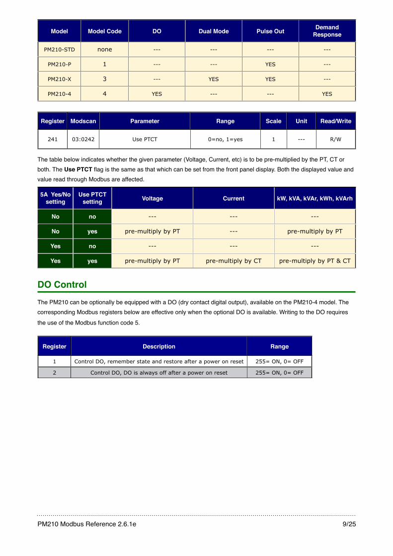
Model Model Code DO Dual Mode Pulse Out Demand Response
PM210-STD none --- --- --- ---
PM210-P 1 --- --- YES ---
PM210-X 3 --- YES YES ---
PM210-4 4 YES --- --- YES
Register Modscan Parameter Range Scale Unit Read/Write
241 03:0242 Use PTCT 0=no, 1=yes 1 --- R/W
The table below indicates whether the given parameter (Voltage, Current, etc) is to be pre-multiplied by the PT, CT or both. The Use PTCT flag is the same as that which can be set from the front panel display. Both the displayed value and value read through Modbus are affected.
5A Yes/Nosetting
Use PTCT setting Voltage Current kW, kVA, kVAr, kWh, kVArh
No no
No yes
Yes no
Yes yes
--- --- ---
pre-multiply by PT --- pre-multiply by PT
--- --- ---
pre-multiply by PT pre-multiply by CT pre-multiply by PT & CT
DO ControlThe PM210 can be optionally be equipped with a DO (dry contact digital output), available on the PM210-4 model. The corresponding Modbus registers below are effective only when the optional DO is available. Writing to the DO requires the use of the Modbus function code 5.
Register Description Range
1 Control DO, remember state and restore after a power on reset 255= ON, 0= OFF
2 Control DO, DO is always off after a power on reset 255= ON, 0= OFF
PM210 Modbus Reference 2.6.1e! 9/25
Examples
Examples
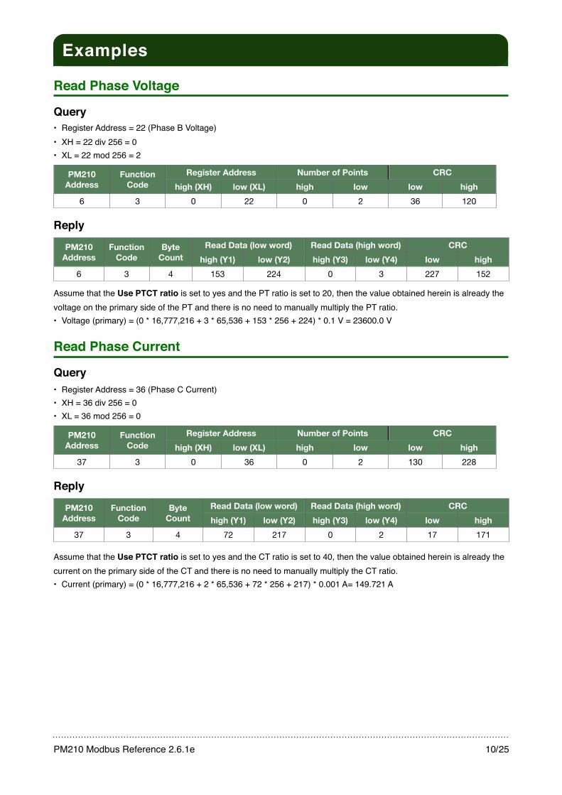
Read Phase Voltage
Query• Register Address = 22 (Phase B Voltage)• XH = 22 div 256 = 0• XL = 22 mod 256 = 2
PM210 Address
Function Code
Register AddressRegister Address Number of PointsNumber of Points CRCCRCPM210 Address
Function Code high (XH) low (XL) high low low high
6 3 0 22 0 2 36 120
Reply
PM210 Address
Function Code
Byte Count
Read Data (low word)Read Data (low word) Read Data (high word)Read Data (high word) CRCCRCPM210 Address
Function Code
Byte Count high (Y1) low (Y2) high (Y3) low (Y4) low high
6 3 4 153 224 0 3 227 152
Assume that the Use PTCT ratio is set to yes and the PT ratio is set to 20, then the value obtained herein is already the voltage on the primary side of the PT and there is no need to manually multiply the PT ratio.• Voltage (primary) = (0 * 16,777,216 + 3 * 65,536 + 153 * 256 + 224) * 0.1 V = 23600.0 V
Read Phase Current
Query• Register Address = 36 (Phase C Current)• XH = 36 div 256 = 0• XL = 36 mod 256 = 0
PM210 Address
Function Code
Register AddressRegister Address Number of PointsNumber of Points CRCCRCPM210 Address
Function Code high (XH) low (XL) high low low high
37 3 0 36 0 2 130 228
Reply
PM210Address
Function Code
Byte Count
Read Data (low word)Read Data (low word) Read Data (high word)Read Data (high word) CRCCRCPM210Address
Function Code
Byte Count high (Y1) low (Y2) high (Y3) low (Y4) low high
37 3 4 72 217 0 2 17 171
Assume that the Use PTCT ratio is set to yes and the CT ratio is set to 40, then the value obtained herein is already the current on the primary side of the CT and there is no need to manually multiply the CT ratio.• Current (primary) = (0 * 16,777,216 + 2 * 65,536 + 72 * 256 + 217) * 0.001 A= 149.721 A
PM210 Modbus Reference 2.6.1e! 10/25
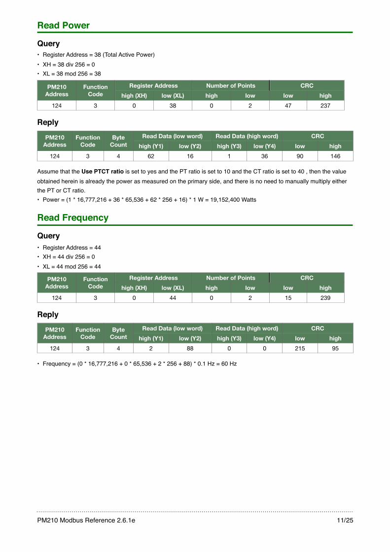
Read Power
Query• Register Address = 38 (Total Active Power)• XH = 38 div 256 = 0• XL = 38 mod 256 = 38
PM210 Address
Function Code
Register AddressRegister Address Number of PointsNumber of Points CRCCRCPM210 Address
Function Code high (XH) low (XL) high low low high
124 3 0 38 0 2 47 237
Reply
PM210 Address
Function Code
Byte Count
Read Data (low word)Read Data (low word) Read Data (high word)Read Data (high word) CRCCRCPM210 Address
Function Code
Byte Count high (Y1) low (Y2) high (Y3) low (Y4) low high
124 3 4 62 16 1 36 90 146
Assume that the Use PTCT ratio is set to yes and the PT ratio is set to 10 and the CT ratio is set to 40 , then the value obtained herein is already the power as measured on the primary side, and there is no need to manually multiply either the PT or CT ratio.• Power = (1 * 16,777,216 + 36 * 65,536 + 62 * 256 + 16) * 1 W = 19,152,400 Watts
Read Frequency
Query• Register Address = 44• XH = 44 div 256 = 0• XL = 44 mod 256 = 44
PM210 Address
Function Code
Register AddressRegister Address Number of PointsNumber of Points CRCCRCPM210 Address
Function Code high (XH) low (XL) high low low high
124 3 0 44 0 2 15 239
Reply
PM210 Address
Function Code
Byte Count
Read Data (low word)Read Data (low word) Read Data (high word)Read Data (high word) CRCCRCPM210 Address
Function Code
Byte Count high (Y1) low (Y2) high (Y3) low (Y4) low high
124 3 4 2 88 0 0 215 95
• Frequency = (0 * 16,777,216 + 0 * 65,536 + 2 * 256 + 88) * 0.1 Hz = 60 Hz
PM210 Modbus Reference 2.6.1e! 11/25

Read Power Factor
Query• Register Address = 46• XH = 46 div 256 = 0• XL = 46 mod 256 = 46
PM210 Address
Function Code
Register AddressRegister Address Number of PointsNumber of Points CRCCRCPM210 Address
Function Code high (XH) low (XL) high low low high
210 3 0 46 0 2 183 161
Reply
PM210 Address
Function Code
Byte Count
Read Data (low word)Read Data (low word) Read Data (high word)Read Data (high word) CRCCRCPM210 Address
Function Code
Byte Count high (Y1) low (Y2) high (Y3) low (Y4) low high
210 3 4 3 102 0 0 248 165
• Data = (Y3 * 16,777,216 + Y4 * 65,536 + Y1 * 256 + Y2) * unit• Frequency = (0 * 16,777,216 + 0 * 65,536 + 3 * 256 + 102) * 0.001 = 0.87
Read Total Active Energy (kWh)
Query• Register Address = 48• XH = 48 div 256 = 0• XL = 48 mod 256 = 48
PM210 Address
Function Code
Register AddressRegister Address Number of PointsNumber of Points CRCCRCPM210 Address
Function Code high (XH) low (XL) high low low high
196 3 0 48 0 2 213 81
Reply
PM210 Address
Function Code
Byte Count
Read Data (low word)Read Data (low word) Read Data (high word)Read Data (high word) CRCCRCPM210 Address
Function Code
Byte Count high (Y1) low (Y2) high (Y3) low (Y4) low high
196 3 4 187 245 0 9 155 239
Assume that the Use PTCT ratio is set to yes, then the value obtained herein is already the total active energy, and there is no need to manually multiply the PT or CT ratio. • Frequency = (0 * 16,777,216 + 9 * 65,536 + 187 * 256 + 245) * 0.01 kWh = 6379.41 kWh
PM210 Modbus Reference 2.6.1e! 12/25

Write Total kWh
Query• Register Address = 48• XH = 48 div 256 = 0• XL = 48 mod 256 = 48• Total kWh = 6379.41 kWh• Y3 = (6379.41 kwh / 0.01 kWh) div 16,777,216 = 0• Y4 = ((6379.41 kwh / 0.01 kWh) mod 16,777,216) div 65,536 = 9• Y1 = ((6379.41 kwh / 0.01 kWh) mod 65,536) div 256 = 187• Y2 = (6379.41 kwh / 0.01 kWh) mod 256 = 245
PM210 Address
Function Code
Register AddressRegister AddressNumber of RegistersNumber of Registers Byte
Count
Write DataWrite DataWrite DataWrite DataPM210
AddressFunction
Code
Register AddressRegister AddressNumber of RegistersNumber of Registers Byte
Countlow wordlow word high wordhigh word CRCCRCPM210
AddressFunction
Codehigh (XH) low (XL) high low
Byte Count
high (Y1) low (Y2) high (Y3) low (Y4) low high
79 16 0 48 0 2 4 187 245 0 9 101 66
Reply
PM210Address
Function Code
Register AddressRegister Address Number of RegistersNumber of Registers CRCCRCPM210Address
Function Code high (XH) low (XL) high low low high
79 16 0 48 0 2 78 41
Read DO StatusNote that the DO status can be read from either register 14 or 142, while the DI status can be read from either register 15 or 143.
Query• Register Address = 142• XH = 142 div 256 = 0• XL = 142 mod 256 = 142
PM210 Address
Function Code
Register AddressRegister Address Number of PointsNumber of Points CRCCRCPM210 Address
Function Code high (XH) low (XL) high low low high
19 3 0 142 0 1 231 83
Reply
PM210 Address
Function Code
Byte Count
Read Data (low word)Read Data (low word) CRCCRCPM210 Address
Function Code
Byte Count high (Y1) low (Y2) low high
19 3 2 0 1 193 135
• DO Status = {0 => Off, 1 => On}.index(1) = On
PM210 Modbus Reference 2.6.1e! 13/25

Control DO
Example 1 (Turn DO on and restore after a Power On Reset)
Input• PM210 Address = 1• DO = ON, restore after a Power on Reset
Query / Reply
PM210 Address
Function Code
Starting RegisterStarting Register Force DataForce Data CRCCRCPM210 Address
Function Code high low high low low high
1 5 0 1 255 0 221 250
Output• none
Example 2 (Turn DO off and restore after a Power On Reset)
Input• PM210 Address = 1• DO = OFF, restore after a Power on Reset
Query / Reply
PM210 Address
Function Code
Starting RegisterStarting Register Force DataForce Data CRCCRCPM210 Address
Function Code high low high low low high
1 5 0 1 0 0 156 10
Example 3 (Turn DO on but donʼt restore after a Power On Reset, DO will always be off after a Power On Reset)
Input• PM210 Address = 1• DO = ON, donʼt restore after a Power on Reset
Query / Reply
PM210 Address
Function Code
Starting RegisterStarting Register Force DataForce Data CRCCRCPM210 Address
Function Code high low high (Y1) low low high
1 5 0 2 255 0 45 250
Example 4 (Turn DO off but donʼt restore after a Power On Reset, DO will always be off after a Power On Reset)
Input• PM210 Address = 1• DO = OFF, donʼt restore after a Power on Reset
Query / Reply
PM210 Address
Function Code
Starting RegisterStarting Register Force DataForce Data CRCCRCPM210 Address
Function Code high low high (Y1) low low high
1 5 0 2 0 0 108 10
PM210 Modbus Reference 2.6.1e! 14/25

Read Phase/Wire
Query• Register Address = 128• XH = 128 div 256 = 0• XL = 128 mod 256 = 128
PM210 Address
Function Code
Register AddressRegister Address Number of PointsNumber of Points CRCCRCPM210 Address
Function Code high (XH) low (XL) high low low high
55 3 0 128 0 1 128 116
Reply
PM210 Address
Function Code
Byte Count
Read DataRead Data CRCCRCPM210 Address
Function Code
Byte Count high (Y1) low (Y2) low high
55 3 2 0 1 177 128
• Index = (Y1 * 256 + Y2) * Unit = (0 * 256 + 1) * 1 = 1• Phase/Wire = {0 => 3p4w, 1 => 3p3w-2CT, 2 => 1p3w, 3=3p3w-3CT} [1] = 3p3w-2CT
Read BD15 (15 minute block demand)
Query• Register Address = 52• XH = 52 div 256 = 0• XL = 52 mod 256 = 52
PM210 Address
Function Code
Register AddressRegister Address Number of PointsNumber of Points CRCCRCPM210 Address
Function Code high (XH) low (XL) high low low high
88 3 0 52 0 1 201 13
Reply
PM210 Address
Function Code
Byte Count
Read DataRead Data CRCCRCPM210 Address
Function Code
Byte Count high (Y1) low (Y2) low high
88 3 2 48 212 176 22
• BD15 = (48 * 256 + 212) * 0.1 W = 1250.0 Watts
PM210 Modbus Reference 2.6.1e! 15/25
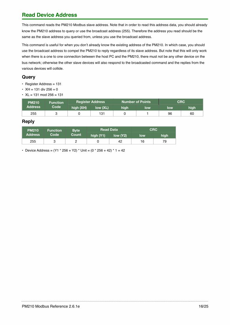
Read Device AddressThis command reads the PM210 Modbus slave address. Note that in order to read this address data, you should already know the PM210 address to query or use the broadcast address (255). Therefore the address you read should be the same as the slave address you queried from, unless you use the broadcast address.
This command is useful for when you donʼt already know the existing address of the PM210. In which case, you should use the broadcast address to compel the PM210 to reply regardless of its slave address. But note that this will only work when there is a one to one connection between the host PC and the PM210, there must not be any other device on the bus network; otherwise the other slave devices will also respond to the broadcasted command and the replies from the various devices will collide.
Query• Register Address = 131• XH = 131 div 256 = 0• XL = 131 mod 256 = 131
PM210 Address
Function Code
Register AddressRegister Address Number of PointsNumber of Points CRCCRCPM210 Address
Function Code high (XH) low (XL) high low low high
255 3 0 131 0 1 96 60
Reply
PM210 Address
Function Code
Byte Count
Read DataRead Data CRCCRCPM210 Address
Function Code
Byte Count high (Y1) low (Y2) low high
255 3 2 0 42 16 79
• Device Address = (Y1 * 256 + Y2) * Unit = (0 * 256 + 42) * 1 = 42
PM210 Modbus Reference 2.6.1e! 16/25
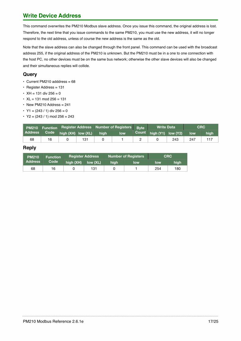
Write Device AddressThis command overwrites the PM210 Modbus slave address. Once you issue this command, the original address is lost. Therefore, the next time that you issue commands to the same PM210, you must use the new address, it will no longer respond to the old address, unless of course the new address is the same as the old.
Note that the slave address can also be changed through the front panel. This command can be used with the broadcast address 255, if the original address of the PM210 is unknown. But the PM210 must be in a one to one connection with the host PC, no other devices must be on the same bus network; otherwise the other slave devices will also be changed and their simultaneous replies will collide.
Query• Current PM210 adddress = 68• Register Address = 131• XH = 131 div 256 = 0• XL = 131 mod 256 = 131• New PM210 Address = 241• Y1 = (243 / 1) div 256 = 0• Y2 = (243 / 1) mod 256 = 243
PM210 Address
Function Code
Register AddressRegister Address Number of RegistersNumber of Registers Byte Count
Write DataWrite Data CRCCRCPM210 Address
Function Code high (XH) low (XL) high low
Byte Count high (Y1) low (Y2) low high
68 16 0 131 0 1 2 0 243 247 117
Reply
PM210Address
Function Code
Register AddressRegister Address Number of RegistersNumber of Registers CRCCRCPM210Address
Function Code high (XH) low (XL) high low low high
68 16 0 131 0 1 254 180
PM210 Modbus Reference 2.6.1e! 17/25
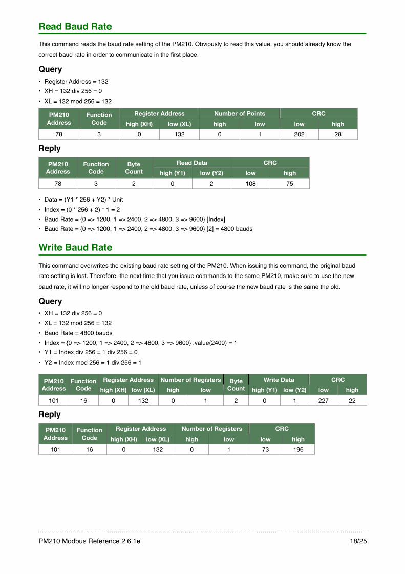
Read Baud RateThis command reads the baud rate setting of the PM210. Obviously to read this value, you should already know the correct baud rate in order to communicate in the first place.
Query• Register Address = 132• XH = 132 div 256 = 0• XL = 132 mod 256 = 132
PM210 Address
Function Code
Register AddressRegister Address Number of PointsNumber of Points CRCCRCPM210 Address
Function Code high (XH) low (XL) high low low high
78 3 0 132 0 1 202 28
Reply
PM210 Address
Function Code
Byte Count
Read DataRead Data CRCCRCPM210 Address
Function Code
Byte Count high (Y1) low (Y2) low high
78 3 2 0 2 108 75
• Data = (Y1 * 256 + Y2) * Unit• Index = (0 * 256 + 2) * 1 = 2• Baud Rate = {0 => 1200, 1 => 2400, 2 => 4800, 3 => 9600} [Index]• Baud Rate = {0 => 1200, 1 => 2400, 2 => 4800, 3 => 9600} [2] = 4800 bauds
Write Baud RateThis command overwrites the existing baud rate setting of the PM210. When issuing this command, the original baud rate setting is lost. Therefore, the next time that you issue commands to the same PM210, make sure to use the new baud rate, it will no longer respond to the old baud rate, unless of course the new baud rate is the same the old.
Query• XH = 132 div 256 = 0• XL = 132 mod 256 = 132• Baud Rate = 4800 bauds• Index = {0 => 1200, 1 => 2400, 2 => 4800, 3 => 9600} .value(2400) = 1• Y1 = Index div 256 = 1 div 256 = 0• Y2 = Index mod 256 = 1 div 256 = 1
PM210 Address
Function Code
Register AddressRegister Address Number of RegistersNumber of Registers Byte Count
Write DataWrite Data CRCCRCPM210 Address
Function Code high (XH) low (XL) high low
Byte Count high (Y1) low (Y2) low high
101 16 0 132 0 1 2 0 1 227 22
Reply
PM210Address
Function Code
Register AddressRegister Address Number of RegistersNumber of Registers CRCCRCPM210Address
Function Code high (XH) low (XL) high low low high
101 16 0 132 0 1 73 196
PM210 Modbus Reference 2.6.1e! 18/25
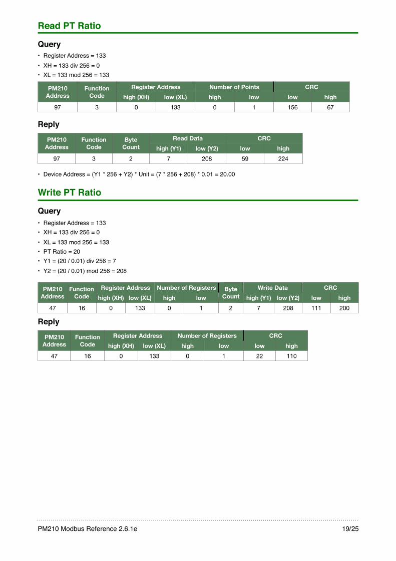
Read PT Ratio
Query• Register Address = 133• XH = 133 div 256 = 0• XL = 133 mod 256 = 133
PM210 Address
Function Code
Register AddressRegister Address Number of PointsNumber of Points CRCCRCPM210 Address
Function Code high (XH) low (XL) high low low high
97 3 0 133 0 1 156 67
Reply
PM210 Address
Function Code
Byte Count
Read DataRead Data CRCCRCPM210 Address
Function Code
Byte Count high (Y1) low (Y2) low high
97 3 2 7 208 59 224
• Device Address = (Y1 * 256 + Y2) * Unit = (7 * 256 + 208) * 0.01 = 20.00
Write PT Ratio
Query• Register Address = 133• XH = 133 div 256 = 0• XL = 133 mod 256 = 133• PT Ratio = 20• Y1 = (20 / 0.01) div 256 = 7• Y2 = (20 / 0.01) mod 256 = 208
PM210 Address
Function Code
Register AddressRegister Address Number of RegistersNumber of Registers Byte Count
Write DataWrite Data CRCCRCPM210 Address
Function Code high (XH) low (XL) high low
Byte Count high (Y1) low (Y2) low high
47 16 0 133 0 1 2 7 208 111 200
Reply
PM210Address
Function Code
Register AddressRegister Address Number of RegistersNumber of Registers CRCCRCPM210Address
Function Code high (XH) low (XL) high low low high
47 16 0 133 0 1 22 110
PM210 Modbus Reference 2.6.1e! 19/25
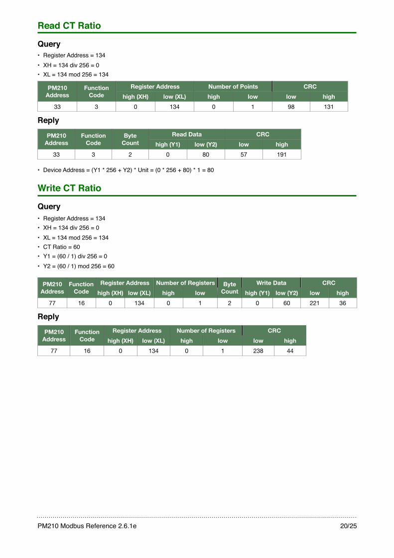
Read CT Ratio
Query• Register Address = 134• XH = 134 div 256 = 0• XL = 134 mod 256 = 134
PM210 Address
Function Code
Register AddressRegister Address Number of PointsNumber of Points CRCCRCPM210 Address
Function Code high (XH) low (XL) high low low high
33 3 0 134 0 1 98 131
Reply
PM210 Address
Function Code
Byte Count
Read DataRead Data CRCCRCPM210 Address
Function Code
Byte Count high (Y1) low (Y2) low high
33 3 2 0 80 57 191
• Device Address = (Y1 * 256 + Y2) * Unit = (0 * 256 + 80) * 1 = 80
Write CT Ratio
Query• Register Address = 134• XH = 134 div 256 = 0• XL = 134 mod 256 = 134• CT Ratio = 60• Y1 = (60 / 1) div 256 = 0• Y2 = (60 / 1) mod 256 = 60
PM210 Address
Function Code
Register AddressRegister Address Number of RegistersNumber of Registers Byte Count
Write DataWrite Data CRCCRCPM210 Address
Function Code high (XH) low (XL) high low
Byte Count high (Y1) low (Y2) low high
77 16 0 134 0 1 2 0 60 221 36
Reply
PM210Address
Function Code
Register AddressRegister Address Number of RegistersNumber of Registers CRCCRCPM210Address
Function Code high (XH) low (XL) high low low high
77 16 0 134 0 1 238 44
PM210 Modbus Reference 2.6.1e! 20/25
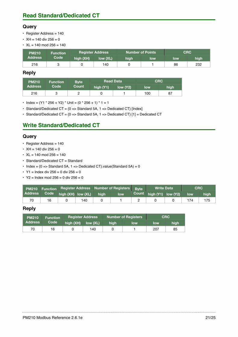
Read Standard/Dedicated CT
Query• Register Address = 140• XH = 140 div 256 = 0• XL = 140 mod 256 = 140
PM210 Address
Function Code
Register AddressRegister Address Number of PointsNumber of Points CRCCRCPM210 Address
Function Code high (XH) low (XL) high low low high
216 3 0 140 0 1 86 232
Reply
PM210 Address
Function Code
Byte Count
Read DataRead Data CRCCRCPM210 Address
Function Code
Byte Count high (Y1) low (Y2) low high
216 3 2 0 1 100 87
• Index = (Y1 * 256 + Y2) * Unit = (0 * 256 + 1) * 1 = 1• Standard/Dedicated CT = {0 => Standard 5A, 1 => Dedicated CT} [Index]• Standard/Dedicated CT = {0 => Standard 5A, 1 => Dedicated CT} [1] = Dedicated CT
Write Standard/Dedicated CT
Query• Register Address = 140• XH = 140 div 256 = 0• XL = 140 mod 256 = 140• Standard/Dedicated CT = Standard • Index = {0 => Standard 5A, 1 => Dedicated CT}.value(Standard 5A) = 0• Y1 = Index div 256 = 0 div 256 = 0• Y2 = Index mod 256 = 0 div 256 = 0
PM210 Address
Function Code
Register AddressRegister Address Number of RegistersNumber of Registers Byte Count
Write DataWrite Data CRCCRCPM210 Address
Function Code high (XH) low (XL) high low
Byte Count high (Y1) low (Y2) low high
70 16 0 140 0 1 2 0 0 174 175
Reply
PM210Address
Function Code
Register AddressRegister Address Number of RegistersNumber of Registers CRCCRCPM210Address
Function Code high (XH) low (XL) high low low high
70 16 0 140 0 1 207 85
PM210 Modbus Reference 2.6.1e! 21/25
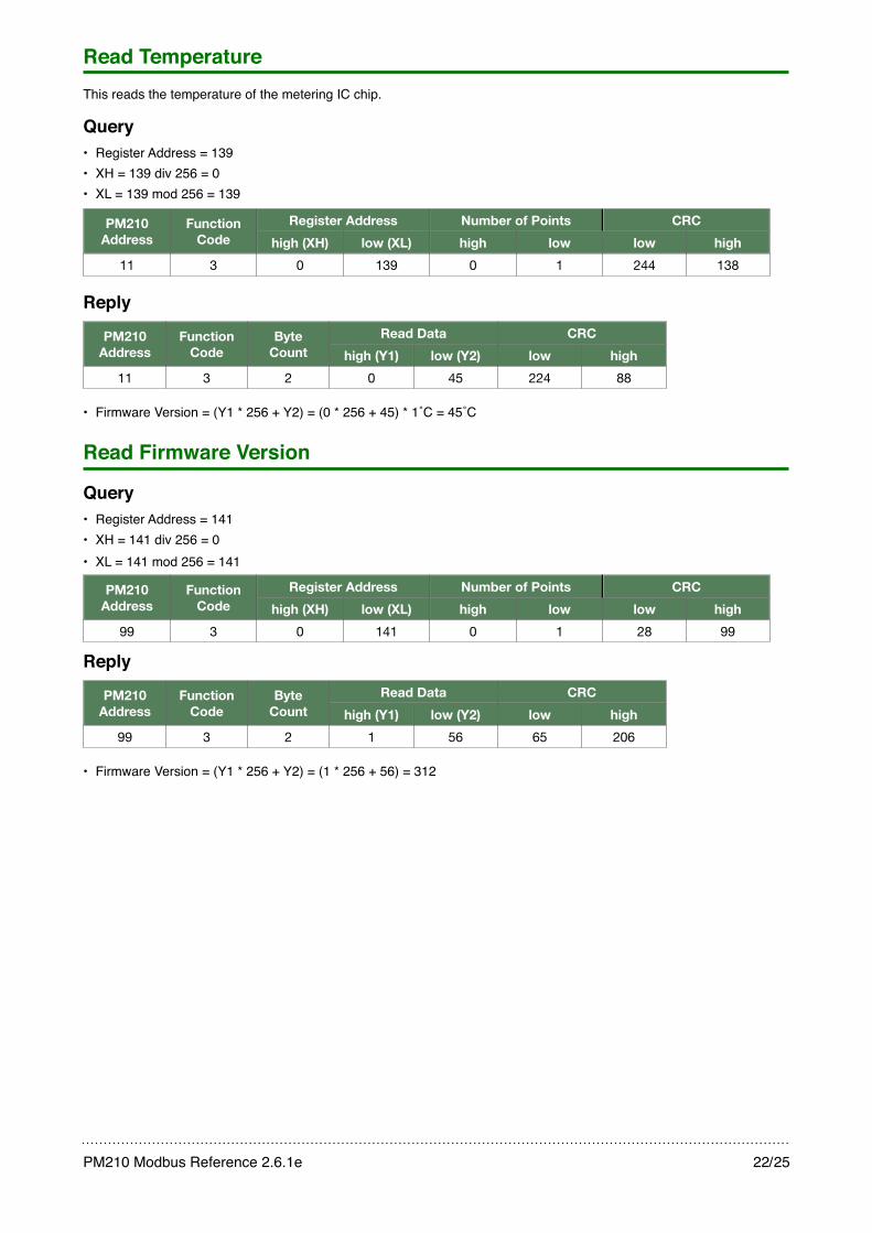
Read TemperatureThis reads the temperature of the metering IC chip.
Query• Register Address = 139• XH = 139 div 256 = 0• XL = 139 mod 256 = 139
PM210 Address
Function Code
Register AddressRegister Address Number of PointsNumber of Points CRCCRCPM210 Address
Function Code high (XH) low (XL) high low low high
11 3 0 139 0 1 244 138
Reply
PM210 Address
Function Code
Byte Count
Read DataRead Data CRCCRCPM210 Address
Function Code
Byte Count high (Y1) low (Y2) low high
11 3 2 0 45 224 88
• Firmware Version = (Y1 * 256 + Y2) = (0 * 256 + 45) * 1˚C = 45˚C
Read Firmware Version
Query• Register Address = 141• XH = 141 div 256 = 0• XL = 141 mod 256 = 141
PM210 Address
Function Code
Register AddressRegister Address Number of PointsNumber of Points CRCCRCPM210 Address
Function Code high (XH) low (XL) high low low high
99 3 0 141 0 1 28 99
Reply
PM210 Address
Function Code
Byte Count
Read DataRead Data CRCCRCPM210 Address
Function Code
Byte Count high (Y1) low (Y2) low high
99 3 2 1 56 65 206
• Firmware Version = (Y1 * 256 + Y2) = (1 * 256 + 56) = 312
PM210 Modbus Reference 2.6.1e! 22/25
CRC Computation
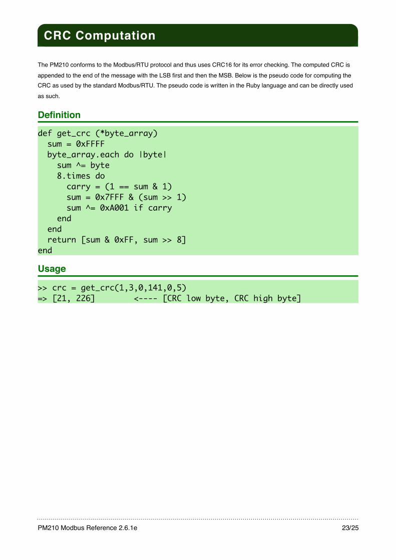
CRC Computation
The PM210 conforms to the Modbus/RTU protocol and thus uses CRC16 for its error checking. The computed CRC is appended to the end of the message with the LSB first and then the MSB. Below is the pseudo code for computing the CRC as used by the standard Modbus/RTU. The pseudo code is written in the Ruby language and can be directly used as such.
Definition
def get_crc (*byte_array) sum = 0xFFFF byte_array.each do |byte| sum ^= byte 8.times do carry = (1 == sum & 1) sum = 0x7FFF & (sum >> 1) sum ^= 0xA001 if carry end end return [sum & 0xFF, sum >> 8]end
Usage
>> crc = get_crc(1,3,0,141,0,5)=> [21, 226] <---- [CRC low byte, CRC high byte]
PM210 Modbus Reference 2.6.1e! 23/25

Notes on Modscan
This is not a manual of Modscan, but only a short note describing its manual commands capability.
Most users are familiar with Modscanʼs ability to read and continuously poll a designated device using Modbus commands 1 to 4. But in addition, Modscan also has the ability to issue other commands as well.
For the DEM, function code 5 and 16 needs to be issued as well. To issue them, first make sure that the connection has already been established and running then go to the menu and run the dialog box “User Defined Command String” from [Setup->Extended->User Msg] as shown in the screen captures below:
Notes on Modscan
PM210 Modbus Reference 2.6.1e! 24/25

Additional Resources
Additional ResourcesAlthough every effort has been taken to ensure that this document is free from errors, some may still remain. If found please send an email to: [email protected], in the subject line write “Errata” and please indicate the name of this document “PM210 Modbus Reference”, revision number, page number and indicate the error with its correction. Thank you.
We have made sure that this document is as clear and useful to you as possible, but any suggestions on improving this document to serve you even better would be welcome. Send comments and suggestions to: [email protected], in the subject line, write “Comments” and please indicate the name of this document “PM210 Modbus Reference”. Questions are also welcome.
This document only covers the Modbus protocol registers as used by the PM210, for interfacing and other information please refer to the PM210 userʼs manual.
PM210 Modbus Reference 2.6.1e! 25/25