
Plug-in option FR-A8ND - MITSUBISHI ELECTRIC...
104
INVERTER INVERTER Plug-in option INSTRUCTION MANUAL PRE-OPERATION INSTRUCTIONS 1 INSTALLATION 2 WIRING 3 INVERTER SETTING 4 FUNCTIONS 5 OBJECT MAP DEFINITIONS 6 OBJECT MAP 7 FR-A8ND communication function
Transcript of Plug-in option FR-A8ND - MITSUBISHI ELECTRIC...

FR-A8ND INSTRUCTION M
ANUAL
B
INV
ER
TER
INVERTERPlug-in option
INSTRUCTION MANUAL
INVERTER
PRE-OPERATION INSTRUCTIONS 1INSTALLATION 2WIRING 3INVERTER SETTING 4FUNCTIONS 5OBJECT MAP DEFINITIONS 6OBJECT MAP 7
FR-A8ND
communication function
IB(NA)-0600511ENG-B(1410) MEE Printed in Japan Specifications subject to change without notice.
HEAD OFFICE: TOKYO BUILDING 2-7-3, MARUNOUCHI, CHIYODA-KU, TOKYO 100-8310, JAPAN

1
Thank you for choosing this Mitsubishi inverter plug-in option.orrect handling might cause an unexpected orrectly.
s Instruction Manual and appended a full knowledge of the equipment, safety d into "Warning" and "Caution".r severe injury.
or slight injury, or may cause only material
. Both instruction levels must be followed
front cover or the wiring cover removed. Otherwise ck.uld be when performing wiring and periodic
on who is involved in wiring or inspection shall wait ge using a tester or the like. For some time after the
lectric shock.
amage, etc. may occur.
se devices may cause a burn.
This Instruction Manual provides handling information and precautions for use of this product. Incfault. Before using this product, always read this Instruction Manual carefully to use this product cPlease forward this Instruction Manual to the end user.
Electric Shock Prevention
Injury Prevention
Safety instructionsDo not attempt to install, operate, maintain or inspect the product until you have read through thidocuments carefully and can use the equipment correctly. Do not use this product until you haveinformation and instructions. In this Instruction Manual, the safety instruction levels are classifie
Incorrect handling may cause hazardous conditions, resulting in death o
Incorrect handling may cause hazardous conditions, resulting in mediumdamage.
The level may even lead to a serious consequence according to conditions
because these are important to personal safety.
Warning While the inverter power is ON, do not open the front cover or the wiring cover. Do not run the inverter with the
you may access the exposed high voltage terminals or the charging part of the circuitry and get an electric sho Do not remove the inverter front cover even if the power supply is disconnected. The only exception for this wo
inspection. You may accidentally touch the charged inverter circuits and get an electric shock. Before wiring or inspection, LED indication of the inverter unit operation panel must be switched OFF. Any pers
for at least 10 minutes after the power supply has been switched OFF and check that there is no residual voltapower-OFF, a high voltage remains in the smoothing capacitor, and it is dangerous.
Any person who is involved in wiring or inspection of this equipment shall be fully competent to do the work. The plug-in option must be installed before wiring. Otherwise you may get an electric shock or be injured. Do not touch the plug-in option or handle the cables with wet hands. Otherwise you may get an electric shock. Do not subject the cables to scratches, excessive stress, heavy loads or pinching. Otherwise you may get an e
Caution The voltage applied to each terminal must be the ones specified in the Instruction Manual. Otherwise a burst, d The cables must be connected to the correct terminals. Otherwise a burst, damage, etc. may occur. The polarity (+ and -) must be correct. Otherwise a burst or damage may occur. While power is ON or for some time after power OFF, do not touch the inverter as it will be extremely hot. Touching the
Warning
Caution
Caution

Additional Instructionse unexpected fault, an injury, or an electric
ents or other flammable substance such as oil.uct will be damaged. Halogen-based materials are esidual fumigant components from being infiltrated ckaging. Sterilization of disinfection of wooden
machines to make unexpected motions.
e product.
tarting operations. Because all parameters return to
n for explanation. Never operate the inverter in this erating the inverter.
2
The following instructions must be also followed. If the product is handled incorrectly, it may causshock.
CautionTransportation and mounting Do not install or operate the plug-in option if it is damaged or has parts missing. Do not stand or rest heavy objects on the product. The mounting orientation must be correct. Foreign conductive objects must be prevented from entering the inverter. That includes screws and metal fragm If halogen-based materials (fluorine, chlorine, bromine, iodine, etc.) infiltrate into a Mitsubishi product, the prod
often included in fumigant, which is used to sterilize or disinfest wooden packages. When packaging, prevent rinto Mitsubishi products, or use an alternative sterilization or disinfection method (heat disinfection, etc.) for papackage should also be performed before packaging the product.
Trial run Before starting operation, each parameter must be confirmed and adjusted. A failure to do so may cause some
WarningUsage Do not modify the equipment. Do not perform parts removal which is not instructed in this manual. Doing so may lead to fault or damage of th
CautionUsage When parameter clear or all parameter clear is performed, the required parameters must be set again before s
their initial values. Static electricity in your body must be discharged before you touch the product.Maintenance, inspection and parts replacement Do not carry out a megger (insulation resistance) test.Disposal The inverter must be treated as industrial waste.
General instruction Many of the diagrams and drawings in this Instruction Manual show the inverter without a cover or partially ope
manner. The cover must be reinstalled and the instructions in the Instruction Manual must be followed when op

3
6..............................................................6..............................................................7..............................................................8............................................................10
11............................................................11............................................................12............................................................16
18............................................................18............................................................19
22............................................................22............................................................23................................................................ 24................................................................ 25............................................................27................................................................ 27............................................................309) .......................................................... 30
................................................................ 34
............................................................35
............................................................37
─ CONTENTS ─1 PRE-OPERATION INSTRUCTIONS1.1 Unpacking and product confirmation..............................................................1.2 Component names ............................................................................................1.3 MNS LED (operation status indication) ...........................................................1.4 Specifications ....................................................................................................
2 INSTALLATION2.1 Pre-installation instructions .............................................................................2.2 Installation procedure .......................................................................................2.3 Node address setting ........................................................................................
3 WIRING3.1 Connection to network......................................................................................3.2 Wiring..................................................................................................................
4 INVERTER SETTING4.1 Parameter list .....................................................................................................4.2 DeviceNet data ...................................................................................................
4.2.1 DeviceNet address (Pr. 345)...............................................................................4.2.2 DeviceNet baud rate (Pr. 346) ............................................................................
4.3 Operation mode setting ....................................................................................4.3.1 Operation mode switching and communication startup mode (Pr.79, Pr.340)....
4.4 Operation at communication error occurrence ..............................................4.4.1 Operation selection at communication error occurrence (Pr.500 to Pr.502, Pr.774.4.2 Fault and measures ............................................................................................
4.5 Inverter reset ......................................................................................................4.6 Frequency and speed settings.........................................................................
38............................................................38............................................................39
40............................................................40............................................................41................................................................ 41................................................................ 42............................................................43................................................................ 43............................................................... 44............................................................44
45............................................................45................................................................ 45................................................................ 47................................................................ 49................................................................ 53............................................................59................................................................ 59................................................................ 61................................................................ 63................................................................ 64................................................................ 71................................................................ 72................................................................ 75................................................................ 81................................................................ 88................................................................ 90................................................................ 91
4
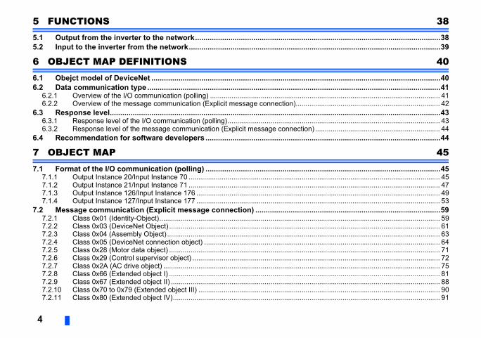
5 FUNCTIONS5.1 Output from the inverter to the network..........................................................5.2 Input to the inverter from the network.............................................................
6 OBJECT MAP DEFINITIONS6.1 Obejct model of DeviceNet ...............................................................................6.2 Data communication type.................................................................................
6.2.1 Overview of the I/O communication (polling) ......................................................6.2.2 Overview of the message communication (Explicit message connection)..........
6.3 Response level...................................................................................................6.3.1 Response level of the I/O communication (polling).............................................6.3.2 Response level of the message communication (Explicit message connection) .
6.4 Recommendation for software developers .....................................................
7 OBJECT MAP7.1 Format of the I/O communication (polling) .....................................................
7.1.1 Output Instance 20/Input Instance 70 .................................................................7.1.2 Output Instance 21/Input Instance 71 .................................................................7.1.3 Output Instance 126/Input Instance 176 .............................................................7.1.4 Output Instance 127/Input Instance 177 .............................................................
7.2 Message communication (Explicit message connection) .............................7.2.1 Class 0x01 (Identity-Object)................................................................................7.2.2 Class 0x03 (DeviceNet Object) ...........................................................................7.2.3 Class 0x04 (Assembly Object) ............................................................................7.2.4 Class 0x05 (DeviceNet connection object) .........................................................7.2.5 Class 0x28 (Motor data object) ...........................................................................7.2.6 Class 0x29 (Control supervisor object) ...............................................................7.2.7 Class 0x2A (AC drive object) ..............................................................................7.2.8 Class 0x66 (Extended object I) ...........................................................................7.2.9 Class 0x67 (Extended object II) ..........................................................................7.2.10 Class 0x70 to 0x79 (Extended object III) ............................................................7.2.11 Class 0x80 (Extended object IV).........................................................................

5
7.2.12 Class 0x90 to 0x94 (Extended object V) ............................................................................................................................. 95............................................................96
99
............................................................99
..........................................................100
7.3 FR-A5ND compatible mode ..............................................................................
APPENDIX
Appendix 1 EDS file..................................................................................................Appendix 2 DeviceNet Error Code List...................................................................
the product is as you ordered and intact.
sociation, INC).
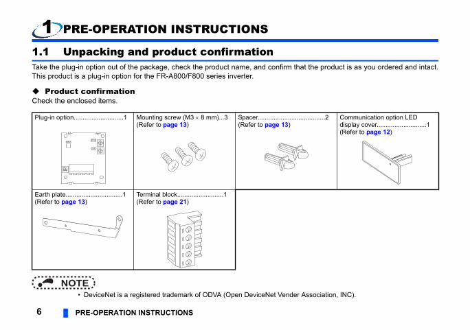
.........2 Communication option LEDdisplay cover............................1(Refer to page 12)
6 PRE-OPERATION INSTRUCTIONS
1 PRE-OPERATION INSTRUCTIONS
1.1 Unpacking and product confirmationTake the plug-in option out of the package, check the product name, and confirm that This product is a plug-in option for the FR-A800/F800 series inverter.
Product confirmationCheck the enclosed items.
NOTE • DeviceNet is a registered trademark of ODVA (Open DeviceNet Vender As
Plug-in option............................1 Mounting screw (M3 8 mm)...3(Refer to page 13)
Spacer.............................(Refer to page 13)
Earth plate................................1(Refer to page 13)
Terminal block..........................1(Refer to page 21)
09
87 6 54
321
09
87 6 54
321
X10
X1
ON
1 2
MNS

ERATION INSTRUCTIONS 7
1Refer to page
or installs spacers. 13
ect to the network. 21
ration status. 8
"0" is set for both X10 16
de.e both OFF.) 96
13
nge from the initially-—
w
ON
(f)
(a)
(a)
(g)
PRE-OP
1.2 Component names
Symbol Name Description
a Mounting hole Fixes the option to the inverter with screws,
b Connector for communication Mount the accessory terminal block to conn
c MNS LED (operation status indication) Lit/flicker/off of the LED indicate inverter ope
d Node address switch Set the node address. (In the initial setting, and X1.)
e Compatible mode switch Switch over to the FR-A5ND compatible mo(In the initial status, the switches 1 and 2 ar
f Connector Connect to the inverter option connector.
g Switch for manufacturer settingSwitch for manufacturer setting. Do not chaset status (OFF ).
Front view Rear vie(b)
(c)
(e)
V+C+SLDC-V-
09
87 6 5 4
321
09
87 6 5 4
321
X10
X1
ON
1 2
(a)MNS
(a)
(a)(a)
(d)
ON

ot change the setting while the power is
e action
onnector contact fault, and misplaced
6) and master.
s switches and Pr.345) of the inverter.
/O communication from the master matches to check the I/O communication size of the aster device.)
8 PRE-OPERATION INSTRUCTIONS
NOTE • Set the compatible mode switch before switching ON the inverter and do n
ON. Otherwise you may get an electric shock. • Do not turn ON the switch 2 of the compatible mode switch.
1.3 MNS LED (operation status indication)The MNS LED indicates the operating status of the option unit by its indication status.Check the position of LED on page 7.
LED indicator Description Correctiv
OFF
Inverter power OFF Supply power to the inverter.
Network power OFF Supply power to the network.
Cable disconnected Check for a DeviceNet cable disconnection, cterminating resistor.
Own node only on the network Supply power to the master.
Different baud rate between the inverter and master Set the same baud rate for the inverter (Pr.34
Green (flickering)
Connection not established (Cable connection and network power are normal.)
Check the node address setting (node addres
Set the master to the RUN mode.
Check that the size (number of bytes) of the Iwith that set in Pr.346 of the inverter. (For howmaster, refer to the Instruction Manual of the m

ERATION INSTRUCTIONS 9
1
operation, a communication error occurs. For the
e green LED ON>master to the I/O communication format ta to be sent from the master, refer to the
n mode, Pr.338 Communication operation e operation command source selection =
g of the I/O communication of the master
n Manual of the master device.)
onnector contact fault, and misplaced
ork so that the power does not turn OFF
g with those of other devices.
6) and master.
8ND) with terminating resistors, check for a and network power supply drop.
e action
PRE-OP
If the communication is set as the operation or speed command source for the inverter inverter operation at communication error, refer to page 31.
Time limit = 4 EPR.(EPR = Expected Pack Rate Class 0x05 Instance 2 Attribute 9 (Refer to page 66))
Green (ON)
Connection established (The inverter power is ON and the master on the network has recognized this option unit. The green LED stays ON during communication.)
<When the inverter is not running even with th• Check that the correct data is sent from the
specified in Pr.346. (For how to check the daInstruction Manual of the master device.)
• Check that the inverter is in the NET operatiocommand source = "0", or Pr.550 NET mod"0 or 9999".
Red (flickering)
I/O communication connection timeout
Check the EPR (Expected Packet Rate) settinagain.(For how to set the EPR, refer to the Instructio
Check for a DeviceNet cable disconnection, cterminating resistor.
Network power OFF Review the power supply method for the netwagain.
Red (ON)
Overlapping node address Check that the node address is not overlappin
Incorrect baud rate setting Set the same baud rate for the inverter (Pr.34
Communication error due to cable disconnection or intermittent network power OFF
After connecting a master to an inverter (FR-Acable disconnection, connector contact fault,
LED indicator Description Correctiv

10 PRE-OPERATION INSTRUCTIONS
1.4 Specifications
Item Specifications
Powersupply
Control powersupply Supplied from the inverter
Network power Input voltage: 11 to 28 VConsumption current: 90 mA maximum
Connector type Open-type connector
DeviceNet communication specifications Conforms to ODVA DeviceNet Specification. Group2 server. Support UCMM
Communication cable Use a DeviceNet standard thick or thin cable
Maximum cable length500 m (125 kbps)250 m (250 kbps)100 m (500 kbps)
Communication speed 125 kbps, 250 kbps, 500 kbps
Number of invertersconnected
64 (including master)The number of inverters connectable is 64 - 1 = 63 when a minimum of one node as a master is connected.
Response time Refer to page 43.
INSTALLATION 11
2
er and plug-in option may be damaged.rged before you touch the product.
2 INSTALLATION
2.1 Pre-installation instructionsCheck that the inverter's input power and the control circuit power are both OFF.
Caution With input power ON, do not install or remove the plug-in option. Otherwise, the invert To avoid damage due to static electricity, static electricity in your body must be discha

tailed) of the inverter for details on how
ication option on the inverter front cover.
r of the front cover.
Cut off with a nipper, etc.
Cut off with a nipper, etc.
unication option LED cover
12 INSTALLATION
2.2 Installation procedure Installing the communication option LED display cover(1) Remove the inverter front cover. (Refer to Chapter 2 of the Instruction Manual (De
to remove the front cover.)Mount the cover for displaying the operation status indication LED for the commun
(2) Cut off hooks on the rear of the inverter front cover with nipper, etc. and open the window for fitting the LED display cover.
(3) Fit the communication option LED display cover to the front side of the front cover. Align the LED display cover with the LED position on the circuit board of the option. Push the LED display cover until it is fixed with the hooks.
NOTEThe protective structure (JEM1030) changes to the open type (IP00).
Caution Take care not to hurt your hand and such with portions left by cutting hooks of the rea
Comm

INSTALLATION 13
2
Spacer
Inverter sideoption connector
Earth platestallation to connector 1
Installing the option
(1) For the two mounting holes (as shown in the next page) that will not be tightened with mounting screws, insert spacers.
(2) Fit the connector of the plug-in option to the guide of the connector on the inverter unit side, and insert the plug-in option as far as it goes. (Insert it to the inverter option connector 1.)
(3) Fit the one location on the left of the earth plate (as shown in the next page) securely to the inverter unit by screwing in the supplied mounting screw. (tightening torque 0.33 N·m to 0.40 N·m)
(4) Fit the one location on the left of the plug-in option securely to the inverter unit and the right of the plug-in option to the inverter unit together with the earth plate by screwing in the supplied mounting screws. (tightening torque 0.33 N·m to 0.40 N·m) If the screw holes do not line up, the connector may not be inserted deep enough. Check the connector.
Spacer
Example of in

Spacer
Spacer
Mounting screw
Mounting screw
ector 1
s and spacers
Earth plate
14 INSTALLATION
Do not insert the plug-in option to the connector 2 or 3.
ConnConnector 2
Connector 3
Insertion positions for screw
Mounting screw

INSTALLATION 15
2
o not press on the parts on the option re. mounting the plug-in option. it is inserted to the option connector 2 or 3, rate.nnot recognize that the option is mounted
ight, then pull it straight out. Pressure
cur without it.
NOTE • When mounting/removing the plug-in option, hold the sides of the option. D
circuit board. Stress applied to the parts by pressing, etc. may cause a failu • Caution must be applied to mounting screws falling off when removing and • When using this plug-in option, insert it to the inverter option connector 1. If
the protective function (E.2 or E.3) is activated and the inverter will not ope • Even if the option is inserted to the option connector 1, when the inverter ca
due to improper installation, etc., the protective function (E.1) is activated.
• When removing the plug-in option, remove the two screws on the left and rapplied to the connector and to the option board may break the option.
• Always attach the earth plate because a malfunction due to noises may oc
Mounted position Fault indication
Option connector 1
Option connector 2
Option connector 3

-A8ND board. (Refer to page 7.)
s.
change the setting while the power is ON.
witch is set between numbers, normal data
s set by Pr.345 or in "Class 0x03, Instance
ot be established properly.)
d the "6" of X1 to "6".09
87 6 5 4
321
09
87 6 5 4
321
X10
X1
16 INSTALLATION
2.3 Node address setting Setting with node address switchSet the node address between "0 and 63" using the node address switches on the FRThe setting is applied at the next power-ON or inverter reset.Set the arrow () of the corresponding switches to the number to set a desired addres • Setting example
NOTE • Set the inverter node address before switching ON the inverter and do not
Otherwise you may get an electric shock. • Set the node address switch to the switch number position correctly. If the s
communication can not be made.
• When the node address switches are set to "64 or higher", the node addres1, Attribute 1" becomes valid.
• You cannot set the same node address to other devices on the network.(If different devices have the same node address, the communication cann
Node address 1:Set the "" of X10 to "0" and the "" of X1 to "1".
Node address 26:Set the "" of X10 to "2" an
09
87 6 5 4
321
09
87 6 5 4
321
X10
X1
09
87 6 5 4
321 09
87 6 5 4
321
Goodexample
Badexample

INSTALLATION 17
2
r.345 DeviceNet address). When the e setting is applied at the next power-
ttribute 1" using the master. The setting e address switch setting is valid. (Refer
Set with parameter (Pr.345)After setting the node address switches to "64 or higher", set the inverter parameter (Pnode address switches are set to "0 to 63", the node address switch setting is valid. ThON or inverter reset. (Refer to page 24)
Setting with masterAfter setting the node address switches to "64 or higher", set "Class 0x03, Instance 1, Avalue is applied to Pr.345. When the node address switches are set to "0 to 63", the nodto page 61)All connections are released and a set value is immediately applied.
0.)
.)-) of the trunk cable. These resistors
verter
k cable Trunk connector
Drop cable
Terminatingresistor
18 WIRING
3 WIRING
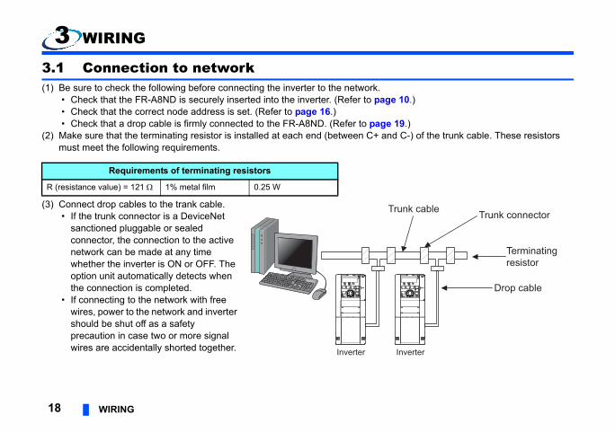
3.1 Connection to network(1) Be sure to check the following before connecting the inverter to the network.
• Check that the FR-A8ND is securely inserted into the inverter. (Refer to page 1 • Check that the correct node address is set. (Refer to page 16.) • Check that a drop cable is firmly connected to the FR-A8ND. (Refer to page 19
(2) Make sure that the terminating resistor is installed at each end (between C+ and Cmust meet the following requirements.
(3) Connect drop cables to the trank cable. • If the trunk connector is a DeviceNet
sanctioned pluggable or sealed connector, the connection to the active network can be made at any time whether the inverter is ON or OFF. The option unit automatically detects when the connection is completed.
• If connecting to the network with free wires, power to the network and inverter should be shut off as a safety precaution in case two or more signal wires are accidentally shorted together.
Requirements of terminating resistors
R (resistance value) = 121 1% metal film 0.25 W
In
Trun
Inverter

WIRING 19
3
e the four colored signal wires and the
d is too long, a short circuit may occur
n, do not solder it.
3.2 Wiring(1) Strip the sheath back about 40 mm on the free wire end of the drop cable to expos
silver shield wire.
(2) Strip the sheath back of each signal cable to use. If the length of the sheath pealeamong neighboring wires. If the length is too short, wires might come off.Wire the stripped cable after twisting it to prevent it from becoming loose. In additio
Use a blade type terminal as required.
Cable stripping length
7 mm

t 0 to 0.5 mm from a sleeve.e terminal of which the crimping is
er Crimping toolname
t CRIMPFOX 6
tipWires are not insertedinto the sleeve
Unstrandedwires
20 WIRING
NOTE • Blade terminals available on the market (as of February 2012)
Insert wires to a blade terminal, and check that the wires come out for abouCheck the condition of the blade terminal after crimping. Do not use a bladinappropriate, or the face is damaged.
Terminalscrew size
Wire size(mm2)
Ferrule terminal modelManufacturWith insulation
sleeveWithout insulation
sleeve
M30.3 to 0.5 AI 0,5-6WH A 0,5-6 Phoenix Contac
Co.,Ltd.0.5 to 0.75 AI 0,75-6GY A 0,75-6
CrumpledDamaged
WireWire
SleeveSleeve
0 to 0.5mm
0 to 0.5mm

WIRING 21
3
(3) Loosen the terminal screw and insert the cable into the terminal according to the terminal assignment.
ing can cause a
ion option
mounted, take caution not to let the cables gnetic noises may cause malfunctions.
river
wdrivertip width: 2.5 mm)
re or malfunction.
V- C- C+ V+
Terminal layout
(Bla
ck)
(Blu
e)
(Whi
te)
(Red
)
Shi
elde
d ca
ble
Tighten each cable with fixing screws to the recommended tightening torque.
NOTE • Undertightening can cause cable disconnection or malfunction. Overtighten
short circuit or malfunction due to damage to the screw or unit.
(4) Connect the terminal block to the connector for communication of the communicatmounted on the inverter.
NOTE • When wiring cables to the inverter's RS-485 terminals with a plug-in option
touch the circuit board of the option or of the inverter. Otherwise, electroma
Screw size Tightening torque Cable size Screwd
M3 0.5 N·m to 0.6 N·m 0.3 mm2 to 0.75 mm2 Small flat-blade scre(Tip thickness: 0.4 mm/
Caution After wiring, wire offcuts must not be left in the inverter. They may cause an error, failu

Minimum setting increments
Initialvalue
Refer topage
1 0 27
1 0
1 0
1 0 27
1 0
1 63 24
1 132 25
1 0 30
0.1 s 0 s 30
1 0 31
1 0 31
1 9999
0.01 Hz 9999 31
22 INVERTER SETTING
4 INVERTER SETTING
4.1 Parameter listThe following parameters are used for the communication option (FR-A8ND).Set the values according to need.
Parameters which can be displayed when the plug-in option (FR-A8ND) is mounted. The setting is reflected after inverter reset or at the next power-ON. Refer to the Instruction Manual (Detailed) of the inverter for the parameter details.
Pr. Pr.group Name Setting
range
79 D000 Operation mode selection 0 to 4, 6, 7
338 D010 Communication operation command source 0, 1
339 D011 Communication speed command source 0, 1, 2
340 D001 Communication startup mode selection 0, 1, 2, 10, 12
342 N001 Communication EEPROM write selection 0, 1
345, N200, DeviceNet address 0 to 4095
346, N201, DeviceNet baud rate 0 to 4095
349 N010 Communication reset selection 0, 1
500 N011 Communication error execution waiting time 0 to 999.8 s
501 N012 Communication error occurrence count display 0
502 N013 Stop mode selection at communication error 0, 1, 2, 3
550 D012 NET mode operation command source selection 0, 1, 9999
779 N014 Operation frequency during communication error 0 to 590 Hz, 9999

INVERTER SETTING 23
4
using a DeviceNet configuration tool.ol, refer to the configuration tool manual.
4.2 DeviceNet dataDeviceNet communication startup data can be set with the inverter parameter without For the setting method with an EDS file (Refer to page 99) DeviceNet configuration to

r higher". (Refer to page 16)
vance to enable the inverter to run in the NET
ng Initialvalue
63
Definition
is Node address can be set with DeviceNet Object Class 0x03, Instance1, Attribute1.(Refer to page 61)
zation with the inverter.mmunication may not resume according to lease connection and reestablish to make
en if the inverter is reset and communication
other than "0" in Pr. 340 so that the inverter .
er than "0" is set, the inverter operates as r. 345.
01
dress
24 INVERTER SETTING
4.2.1 DeviceNet address (Pr. 345)
The definition of Pr. 345 is as follows.
To enable the device node address of bit 0 to 5, set the node address switches to "64 o For an error reset via DeviceNet communication, the communication continues.
When operating the inverter through the DeviceNet communication, set Pr.3400 in adoperation mode after the inverter reset.
Pr. Name Setting range Minimum settiincrements
345 DeviceNet address 0 to 4095 1
Bit Item Initialvalue
Settingrange
0 to 5 Device Node Address 63 0 to 63 Node Address (MAC ID) of deviceset between 0 and 63.
11Selection of continuous communication at inverter reset (ResCom)
0
0
Reset the option unit in synchroniWhen connection is timed out, cothe master action. In this case, recommunication enabled.
1
The option unit will not be reset evcontinues.After inverter reset, preset a valuestarts in Network operation mode
12 to 15 Reserved 0 0 Set "0" always. When a value othwhen "63" (initial value) is set in P
23456789101112131415
Reserved
Communication continuation selection (ResCom)
ResCom Device Node AdReserved

INVERTER SETTING 25
4
ng Initialvalue
132
Definition
This value can be set with DeviceNet Object Class 0x03 Instance 1 Attribute 2. (Refer to page 61)
01
Baud Rate
4.2.2 DeviceNet baud rate (Pr. 346)
Set baud rate etc. to start DeviceNet communication.
Pr. Name Setting range Minimum settiincrements
346 DeviceNet baud rate 0 to 4095 1
Bit Item Initialvalue Setting range
0, 1 Baud Rate 0
0, 3 125 kbps
1 250 kbps
2 500 kbps
23456789101112131415
Reserved Input Assembly Output Assembly

communicated data) of the I/O
4) • Set the same value for input assembly and output assembly.
• The value can be set with Control Supervisor Class 0x29 Instance 1 Attribute 140, 141. (Refer to page 72)
5)
7E)
7F)
g. Do
5)
)
)
0)
1)
g. Do
)
the I/O communication
127/177 (8)
924, 927
925
926
Definition
26 INVERTER SETTING
Set Pr.346 according to the baud rate and Output/Input Instances (number of bytes ofcommunication as shown in the following table.
2 to 6 Output Assembly 1
0 Output Instance 20 (0x1
1 Output Instance 21 (0x1
6 Output Instance 126 (0x
7 Output Instance 127 (0x
8, 14 For manufacturer settinnot set.
Other than the above Output Instance 21 (0x1
7 to 11 Input Assembly 1
0 Input Instance 70 (0x46
1 Input Instance 71 (0x47
6 Input Instance 176 (0xB
7 Input Instance 177 (0xB
8, 14 For manufacturer settinnot set.
Other than the above Input Instance 71 (0x47
12 to 15 Reserved 0 0 Set "0" always.
Baud rateOutput/Input Instances (No. of bytes of communicated data) of
20/70 (4) 21/71 (4) 126/176 (6)
125 kbps 0, 3 132 (initial value), 135 792, 795
250 kbps 1 133 793
500 kbps 2 134 794
Bit Item Initialvalue Setting range
INVERTER SETTING 27
4
up mode (Pr.79, Pr.340)
instantaneous power failurecan be selected.ct the network operation mode.
erter.ation mode.ngs of the inverter are correct.m the master in the External operation
ration mode.ode and no communication establishment is recommended., Pr.340.
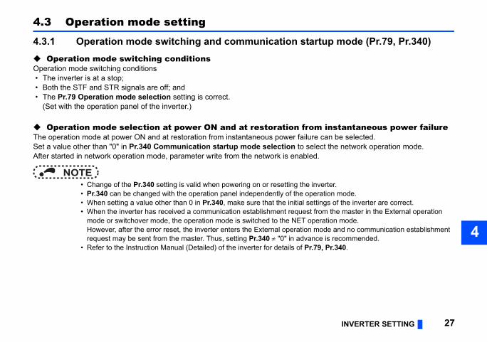
4.3 Operation mode setting
4.3.1 Operation mode switching and communication start Operation mode switching conditionsOperation mode switching conditions • The inverter is at a stop; • Both the STF and STR signals are off; and • The Pr.79 Operation mode selection setting is correct.
(Set with the operation panel of the inverter.)
Operation mode selection at power ON and at restoration fromThe operation mode at power ON and at restoration from instantaneous power failure Set a value other than "0" in Pr.340 Communication startup mode selection to seleAfter started in network operation mode, parameter write from the network is enabled.
NOTE • Change of the Pr.340 setting is valid when powering on or resetting the inv • Pr.340 can be changed with the operation panel independently of the oper • When setting a value other than 0 in Pr.340, make sure that the initial setti • When the inverter has received a communication establishment request fro
mode or switchover mode, the operation mode is switched to the NET opeHowever, after the error reset, the inverter enters the External operation mrequest may be sent from the master. Thus, setting Pr.340 "0" in advance
• Refer to the Instruction Manual (Detailed) of the inverter for details of Pr.79

peration mode switchover
ng the External, PU, and NET operation d ,
ode fixed
een the External and Net operation mode is
e PU operation mode is disallowed
e switching is disallowed
ng the External, PU, and NET operation d while running.
ng the External, PU, and NET operation d ,
tion mode fixed (Forcibly switched to tion mode.)
Pr.340 = "0"
28 INVERTER SETTING
Pr.340setting
Pr.79setting
Operation mode at power ON or power restoration O
0(initial value)
0 (initial value) External operation mode Switching amo
mode is enable
1 PU operation mode PU operation m
2 External operation modeSwitching betwenabled Switching to th
3, 4 External/PU combined operation mode Operation mod
6 External operation mode Switching amomode is enable
7X12 (MRS) signal ON: external operation mode Switching amo
mode is enable
X12 (MRS) signal OFF: external operation mode External operaExternal opera
1, 2
0 NET operation mode
Same as when
1 PU operation mode
2 NET operation mode
3, 4 External/PU combined operation mode
6 NET operation mode
7X12 (MRS) signal ON........ NET operation mode
X12 (MRS) signal OFF........external operation mode

INVERTER SETTING 29
4
ork operation mode.rter RS-485 terminal.er failure) is set in Pr.57 Restart coasting time, een restored from an instantaneous power failure. restored during a start command is on.
peration panel or the X65 signal.
een the PU and NET operation mode is
Pr.340 = "0"
mode fixed
Pr.340 = "0"
een the PU and NET operation mode is running ,
Pr.340 = "0"
peration mode switchover
Operation mode can not be directly changed between the PU operation mode and Netw The Pr.340 settings "2, 12" are mainly used for communication operation using the inve
When a value other than "9999" (selection of automatic restart after instantaneous powthe inverter will resume the same operation state which was in before after power has bWhen Pr.340 = "1, 10", a start command turns off if power failure has occurred and then
Switching between the PU and NET operation modes is available with the key on the o Refer to page 77 for a switching method from the network.
10, 12
0 NET operation mode Switching betwenabled ,
1 PU operation mode Same as when
2 NET operation mode NET operation
3, 4 External/PU combined operation mode Same as when
6 NET operation mode Switching betwenabled while
7 External operation mode Same as when
Pr.340setting
Pr.79setting
Operation mode at power ON or power restoration O

ce
nce (Pr.500 to Pr.502, Pr.779).502, Pr.779 under network operation.
mmunication errorrence can be set.
is recognized as a communication error.unication error, and the operation
inimum settingincrements Initial value
s 0 s
Error
Pr.500tting time
Recognition
ON
30 INVERTER SETTING
4.4 Operation at communication error occurren
4.4.1 Operation selection at communication error occurreYou can select operations at communication error occurrences by setting Pr.500 to Pr
Waiting time for the communication line error output after a coWaiting time for the communication error output after a communication line error occur
When a communication line error occurs and lasts longer than the time set in Pr.500, itIf the communication returns to normal within the time, it is not recognized as a commcontinues.
Pr. Name Setting range M
500 Communication error execution waiting time 0 to 999.8 s 0.1
Normal
se
Normal ErrorCommunication line status
Alarm signal(LF)(Pr.502 = 3)
Pr.500setting time
Communication error(E.OP1)

INVERTER SETTING 31
4
to clear this cumulative count.
urrence count display is incremented
rror count is stored in EEPROM only once be the one that is last stored to EEPROM
set.
inimum setting increments Initial value
0
Description
page 32
communication error occurs, the inverter s at the set frequency.
erter operates at the frequency set before munication error occurs.
Error
Incremented by 1
Displaying and clearing the communication error countThe cumulative count of communication error occurrences can be displayed. Write "0"
At the point of communication line error occurrence, Pr.501 Communication error occby 1.
NOTE • Communication error count is temporarily stored in the RAM memory. The e
per hour. If power reset or converter reset is performed, Pr.501 setting will depending on the reset timing.
Inverter operation at a communication error occurrenceHow the inverter operates at a communication line error or an option unit fault can be
Valid when Pr.502 = "3".
Pr. Name Setting range M
501 Communication error occurrence count display 0 1
Pr. Name Setting range
502 Stop mode selection at communication error 0 (Initial Value), 1, 2, 3 Refer to
779 Operation frequency during communication error0 to 590 Hz When a
operate
9999 (Initial Value) The invthe com
Normal ErrorCount timing depending oncommunication line status Incremented by 1
Normal

About setting
munication option error (E.OP1) does not occur.
independently of the Pr.500 setting.
Fault output
Not provided
Provided
Provided after stop
Fault output
Provided
Provided after stop
Not provided
Kept provided
32 INVERTER SETTING
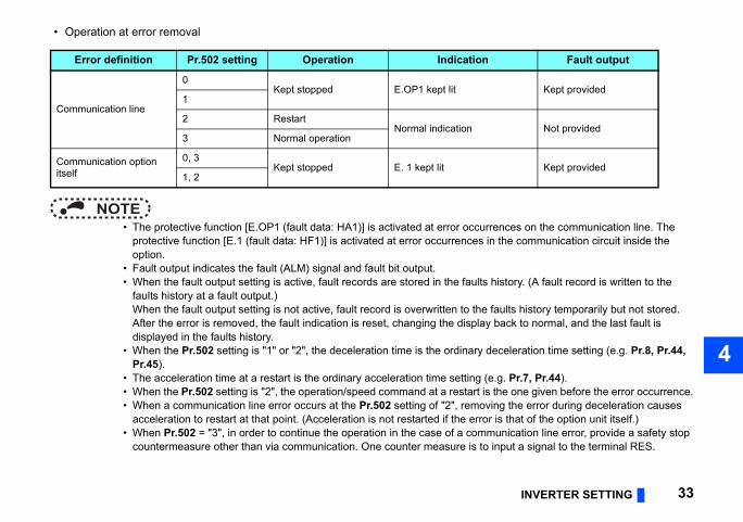
• Operation at an error occurrence
When the communication returns to normal within the time period set in Pr.500, the com
• Operation after the time in Pr.500 elapses after an error occurrence
When an error occurs, the motor is decelerated or coasts to stop, and outputs the fault,
Error definition Pr.502 setting Operation Indication
Communication line
0
Continued Normal indication1
2
3
Communication option itself
0, 3 Coast to stop E. 1 lit
1, 2 Decelerated to stop E. 1 lit after stop
Error definition Pr.502 setting Operation Indication
Communication line
0 Coast to stop E.OP1 lit
1Decelerated to stop E.OP1 lit after stop
2
3 Continues operation with the Pr.779 setting. Normal indication
Communication option itself
0, 3Kept stopped E.OP1 kept lit
1, 2
INVERTER SETTING 33
4
• Operation at error removal
rences on the communication line. The n the communication circuit inside the
history. (A fault record is written to the
faults history temporarily but not stored. back to normal, and the last fault is
eceleration time setting (e.g. Pr.8, Pr.44,
e.g. Pr.7, Pr.44). the one given before the error occurrence.ing the error during deceleration causes r is that of the option unit itself.)
unication line error, provide a safety stop input a signal to the terminal RES.
Fault output
Kept provided
Not provided
Kept provided
NOTE • The protective function [E.OP1 (fault data: HA1)] is activated at error occur
protective function [E.1 (fault data: HF1)] is activated at error occurrences ioption.
• Fault output indicates the fault (ALM) signal and fault bit output. • When the fault output setting is active, fault records are stored in the faults
faults history at a fault output.)When the fault output setting is not active, fault record is overwritten to theAfter the error is removed, the fault indication is reset, changing the displaydisplayed in the faults history.
• When the Pr.502 setting is "1" or "2", the deceleration time is the ordinary dPr.45).
• The acceleration time at a restart is the ordinary acceleration time setting ( • When the Pr.502 setting is "2", the operation/speed command at a restart is • When a communication line error occurs at the Pr.502 setting of "2", remov
acceleration to restart at that point. (Acceleration is not restarted if the erro • When Pr.502 = "3", in order to continue the operation in the case of a comm
countermeasure other than via communication. One counter measure is to
Error definition Pr.502 setting Operation Indication
Communication line
0Kept stopped E.OP1 kept lit
1
2 RestartNormal indication
3 Normal operation
Communication option itself
0, 3Kept stopped E. 1 kept lit
1, 2
s
d) of the inverter and remove the cause of the
eration modernal operation PU operation
er trip Inverter trip
ued Continued
ued Continued
Stop
er trip Inverter trip
ued Continued
ued Continued
Stop
res
move the cause of the alarm. (Refer to page
option connector 1. option unit for poor contact, etc. and remove
34 INVERTER SETTING
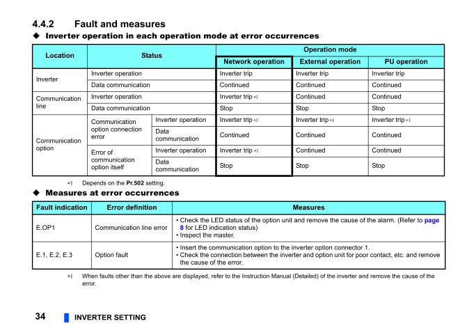
4.4.2 Fault and measures Inverter operation in each operation mode at error occurrence
Depends on the Pr.502 setting.
Measures at error occurrences
When faults other than the above are displayed, refer to the Instruction Manual (Detaileerror.
Location StatusOp
Network operation Exte
InverterInverter operation Inverter trip Invert
Data communication Continued Contin
Communication line
Inverter operation Inverter trip Contin
Data communication Stop Stop
Communication option
Communication option connection error
Inverter operation Inverter trip Invert
Data communication Continued Contin
Error of communication option itself
Inverter operation Inverter trip Contin
Data communication Stop Stop
Fault indication Error definition Measu
E.OP1 Communication line error• Check the LED status of the option unit and re
8 for LED indication status)• Inspect the master.
E.1, E.2, E.3 Option fault• Insert the communication option to the inverter• Check the connection between the inverter and
the cause of the error.

INVERTER SETTING 35
4
below.
the network.twork operation mode in the initial status.ork operation mode again.
. (Refer to page 27.)mand.
Operation mode
rk on
External operation PU operation
Disallowed Disallowed
Allowed Allowed
Disallowed Disallowed
Allowed Allowed
Allowed Allowed
Allowed Allowed
Allowed Allowed
4.5 Inverter reset Operation conditions of inverter resetWhich resetting method is allowed or not allowed in each operation mode is described
Inverter reset can be made any time. Reset can be made only when the protective function of the inverter is activated.
NOTE • When a communication line error has occurred, reset cannot be made from • The inverter is set to the External operation mode if it has been reset in Ne
To resume the network operation, the inverter must be switched to the NetwSet a value other than "0" in Pr.340 to start in the Network operation mode
• The inverter can not be controlled for about 1 s after release of a reset com
Resetting method Netwooperati
Reset from the network
Inverter reset (Class 0x2A, Instance 1, Attribute 101) (Refer to page 77) Allowed
Error reset at inverter fault(Refer to page 45, 47, 49, 53, 73)
Pr.349 = 0Allowed
Pr.349 = 1
Turn on the inverter RES signal (terminal RES) Allowed
Switch off inverter power Allowed
Reset from the PU/DU
Inverter reset Allowed
Reset at inverter fault Allowed

ration mode or PU operation mode.ttribute 12 for error reset commands via
Function
enabled independently of operation mode
enabled only in the network operation mode
36 INVERTER SETTING
Error reset operation selection at inverter faultAn error reset command from communication option can be invalid in the External opeUse Bit2 of Byte0 of Output Instance 20, 21, 126, or 127 and Class 0x29 Instance 1 Athe network. (Refer to page 45, 47, 49, 53, 73.)
Pr. Name Initial value
Setting range
349 Communication reset selection 00 Error reset is
1 Error reset is

INVERTER SETTING 37
4
4.6 Frequency and speed settings • For the output/set frequency monitor, frequency setting, and parameter setting through the FR-A8ND, the unit of 0.01 Hz is
always applied regardless of the Pr.37 Speed display setting. The setting unit for the running speed (actual speed) monitor depends on the Pr.37 and Pr.144 Speed setting switchover settings as shown in the following table. (The initial values are shown within the thick lines.)
Running speed r/min conversion formula: ................... frequency 120 / number of motor poles (Pr.144)Machine speed conversion formula: ............................ Pr.37 frequency / Pr.505 Speed setting referenceFor Pr.144 in the above formula, the value is "Pr.144 - 100" when "102 to 112" is set in Pr.144; and the value is "4" when Pr.37 = 0 and Pr.144 = 0.Pr.505 is always set as frequency (Hz).
Use Pr.811 Set resolution switchover to change the increment from 1 r/min to 0.1 r/min. (Pr.811 is only available for the FR-A800 series.)
• When setting a speed through the FR-A8ND, the speed is calculated with the Pr.144 setting as shown below.
When Pr.144 = "102 to 112," the formula is calculated with the value of (Pr.144 - 100). When Pr.144 = "0", the formula is calculated with 4 poles.
The Pr.811 setting is invalid. The unit 1 r/min is always applied. (Pr.811 is only available for the FR-A800 series.)
NOTE • To apply the unit 1 r/min to the running speed (actual speed) monitor, set the initial values in Pr.37 and Pr.811. • Refer to the Instruction Manual (Detailed) of the inverter for the details of Pr.37, Pr.144, Pr.505 and Pr.811.
Pr.37setting
Pr.144setting
Output frequencymonitor
Set frequency monitor
Running speed (actual speed) monitor
Frequency setting, parameter setting
0(initial value)
0 0.01 Hz 0.01 Hz 1 r/min , 0.01 Hz2 to 12 0.01 Hz 0.01 Hz 1 r/min , 0.01 Hz102 to 112 0.01 Hz 0.01 Hz 1 r/min , 0.01 Hz
1 to 99980 0.01 Hz 0.01 Hz 1 (machine speed ) 0.01 Hz2 to 12 0.01 Hz 0.01 Hz 1 (machine speed ) 0.01 Hz102 to 112 0.01 Hz 0.01 Hz 1 r/min , 0.01 Hz
Speed value (1 r/min ) = frequency 120 / number of motor poles (Pr.144 )
ons are explained below.
ollable from the network in each operation
Refer to page
t current. 78, 91
77
81, 88, 90
77
78
38 FUNCTIONS
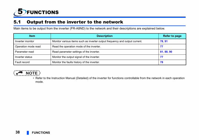
5 FUNCTIONS
5.1 Output from the inverter to the networkMain items to be output from the inverter (FR-A8ND) to the network and their descripti
NOTE • Refer to the Instruction Manual (Detailed) of the inverter for functions contr
mode.
Item Description
Inverter monitor Monitor various items such as inverter output frequency and outpu
Operation mode read Read the operation mode of the inverter.
Parameter read Read parameter settings of the inverter.
Inverter status Monitor the output signal of the inverter.
Fault record Monitor the faults history of the inverter.

FUNCTIONS 39
5
ptions are explained below.
ollable from the network in each operation
Refer to page
45
77
TF) and reverse 45, 77
60, 77
81, 88, 90
60, 77
5.2 Input to the inverter from the networkMain items which can be commanded from the network to the inverter and their descri
NOTE • Refer to the Instruction Manual (Detailed) of the inverter for functions contr
mode.
Item Description
Frequency setting Set the running frequency of the inverter.
Operation mode write Set the operation mode of the inverter.
Run command Set the control input command such as forward operation signal (Srotation signal (STR).
Inverter reset Reset the inverter.
Parameter write Set parameters of the inverter.
Parameter clear Return parameters to the initial values.

ction of particular functions of the
VA.
on of object
40 OBJECT MAP DEFINITIONS
6 OBJECT MAP DEFINITIONS
6.1 Obejct model of DeviceNetFor DeviceNet communication, each node is modeled as collections of objects (abstraproducts). The following four terms are used to describe object.
The following explains object definitions for use of the FR-A8ND DeviceNet.For details of the definitions, consult the DeveiceNet documentation available from OD
Item Definition
Class Collections of all objects which have same types of functions. Generalizati
Instance Concrete expression of object
Attribute Expression of object characteristic
Service Function supported by object or class

BJECT MAP DEFINITIONS 41
6
Explicit message connection)".
Refer to page
on and error reset of the inverter. 45
operation and error reset of the 47
operation, error reset of the erter. 49
operation, error reset of the mmand setting in units of Hz, 53
O
6.2 Data communication typeThe FR-A8ND supports "I/O communication (polling)" and "message communication (
6.2.1 Overview of the I/O communication (polling)Set Output/Input Instances using either of the following methods. • Using Pr.346 (Refer to page 25) • Using Class 0x29 Instance 1 Attribute 140 or 141 (Refer to page 73)
"Output" is a command to the inverter, and "input" is a response from the inverter.
Instance ID (output/input)
No. of bytes of communicated data Function
20/70 4 The following is available: inverter forward operati
21/71 4 The following is available: inverter forward/reverseinverter.
126/176 6 The following is available: inverter forward/reverseinverter, and access to 16-bit parameters of the inv
127/177 8The following is available: inverter forward/reverseinverter, access to 16/32-bit parameters, speed coaccess to inverter input/output terminals.

essage connection) 0x90 to 0x93) through the Explicit
d value exceeds 0xFFFF, the reply data
unication.unication or use the Explicit
ans writing to the inverter.
Drive Object 75
tended Object I 81
tended Object II 88
tended Object III 90
tended Object IV 91
tended Object V 95
Object name Page
42 OBJECT MAP DEFINITIONS
6.2.2 Overview of the message communication (Explicit m • The data size of parameter writing or reading (Class 0x66, 0x67, 0x70 to 0x79, and
message is 2 bytes. • When the 32-bit parameter setting is read through the Explicit message and the rea
will be 0xFFFF. • When reading or writing 32-bit parameters, use Instance 127 or 177 of the I/O comm • When reading 32-bit monitor (Class 0x80), use Instance 127 or 177 of the I/O comm
communication.
NOTE • In the following tables, "Get" means reading from the inverter, and "Set" me
Class Object name Page
0x01 Identity Object 59
0x03 DeviceNet Object 61
0x04 Assembly Object 63
0x05 DeviceNet Connection Object 64
0x28 Motor Data Object 71
0x29 Control Management Object 72
0x2A AC
0x66 Ex
0x67 Ex
0x70 to 0x79 Ex
0x80 Ex
0x90 to 0x93 Ex
Class
BJECT MAP DEFINITIONS 43
6
d setting
A Speed B
Speedcommand B
0ms
O
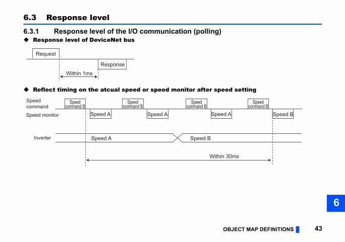
6.3 Response level
6.3.1 Response level of the I/O communication (polling) Response level of DeviceNet bus
Reflect timing on the atcual speed or speed monitor after spee
Request
Response
Within 1ms
Speedcommand B
Speed A
Speed A
Speed A Speed
Speed B
Speedcommand
Speed monitor
Inverter
Speedcommand B
Speedcommand B
Within 3

licit message connection)
s) after sending parameter clear or all
end the next request.e 43.n 50 ms, then send the next request.
44 OBJECT MAP DEFINITIONS
6.3.2 Response level of the message communication (Exp Reading
Writing
Parameter clearingThe inverter will not respond until the parameter clear processing completes (about 5 parameter clear command.
6.4 Recommendation for software developersPlease note the followings when developing software.
• After sending request to the FR-A8ND, wait for response from the FR-A8ND, then s • Set waiting time between each message based on FR-A8ND response time on pag
For example, after sending a writing request by Explicit message, wait for more tha
Request
Response
Within 50ms
Request
Response
Within 50ms

OBJECT MAP 457
2 Bit 1 Bit 0
eset Reserved (0) Run Fwd
1: forward rotation ON)
n the Pr.144 setting. (Refer to page 37)
7 OBJECT MAP
7.1 Format of the I/O communication (polling)
7.1.1 Output Instance 20/Input Instance 70 Output Instance 20 (master → inverter)When using Output Instance 20, set Input Instance to 70.
• Output Instance 20 details
The communication continues during the error reset of the inverter.
Byte Bit 7 Bit 6 Bit 5 Bit 4 Bit 3 Bit
0 Reserved (0) Reserved (0) Reserved (0) Reserved (0) Reserved (0) Fault R
1 Reserved (0x00)
2 Speed reference (low byte)
3 Speed reference (high byte)
Byte0
Bit0 Run Fwd Forward rotation signal (0: forward rotation OFF
Bit2 Fault ResetReset request at an error occurrence Valid only at in inverter trip(0: no function 1: fault reset request)
Byte2Byte3 Speed Ref Speed reference (1 r/min)
Conversion of speed and frequency depends o
2 Bit 1 Bit 0
Reserved (0) Faulted
r is in a fault state)
n)
are effective. (Refer to page 37)
46 OBJECT MAP
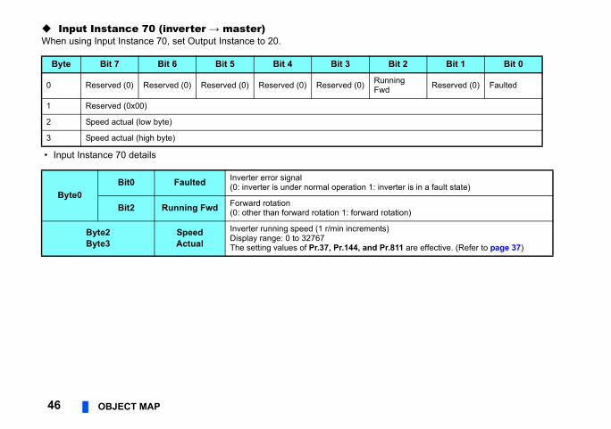
Input Instance 70 (inverter → master)When using Input Instance 70, set Output Instance to 20.
• Input Instance 70 details
Byte Bit 7 Bit 6 Bit 5 Bit 4 Bit 3 Bit
0 Reserved (0) Reserved (0) Reserved (0) Reserved (0) Reserved (0) RunningFwd
1 Reserved (0x00)
2 Speed actual (low byte)
3 Speed actual (high byte)
Byte0Bit0 Faulted Inverter error signal
(0: inverter is under normal operation 1: inverte
Bit2 Running Fwd Forward rotation(0: other than forward rotation 1: forward rotatio
Byte2Byte3
SpeedActual
Inverter running speed (1 r/min increments)Display range: 0 to 32767The setting values of Pr.37, Pr.144, and Pr.811
OBJECT MAP 477
tus remains unchanged.)
2 Bit 1 Bit 0
eset Run Rev Run Fwd
)
Only NetCtrl (Bit 5) = 1 is valid.)
ritten to the inverter.n to the inverter.
erter.r.
n the Pr. 144 setting. (Refer to page 37)t NetRef (Bit6 of Byte0) = "1".
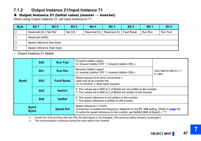
7.1.2 Output Instance 21/Input Instance 71 Output Instance 21 (initial value) (master → inverter)When using Output Instance 21, set Input Instance to 71.
• Output Instance 21 details
If both Run Fwd and Run Rev are ON, the start signal is not changed. (The previous sta The communication continues during the error reset of the inverter.
Byte Bit 7 Bit 6 Bit 5 Bit 4 Bit 3 Bit
0 Reserved (0) Net Ref Net Ctrl Reserved (0) Reserved (0) Fault R
1 Reserved (0x00)
2 Speed reference (low byte)
3 Speed reference (high byte)
Byte0
Bit0 Run Fwd Forward rotation signal (0: forward rotation OFF 1: forward rotation ON
Bit1 Run Rev Reverse rotation signal (0: reverse rotation OFF 1: reverse rotation ON
Bit2 Fault ResetReset request at an error occurrence Valid only at an inverter trip(0: no function 1: fault reset request)
Bit5 NetCtrl 0: The values set in Bit0 to 2 of Byte0 are not w1: The values set in Bit0 to 2 of Byte0 are writte
Bit6 NetRef 0: The speed reference is not written to the inv1: The speed reference is written to the inverte
Byte2Byte3 Speed Ref
Speed reference (1 r/min)Conversion of speed and frequency depends oTo write the speed reference to the inverter, se

t 2 Bit 1 Bit 0
g Fwd Reserved (0) Faulted
n a fault state)
rward rotation)
verse rotation)
ready)
it0 and Bit1 of Byte0.nd Bit1 of Byte0.
ands.s.
te 3. Refer to page 75)
effective. (Refer to page 37)
48 OBJECT MAP
Input Instance 71 (initial value) (inverter → master)When using Input Instance 71, set Output Instance to 21.
• Input Instance 71 details
Byte Bit 7 Bit 6 Bit 5 Bit 4 Bit 3 Bi
0 AtReference Ref From Net
Ctrl From Net Ready Running Rev Runnin
1 Reserved (0x00)
2 Speed actual (low byte)
3 Speed actual (high byte)
Byte0
Bit0 Faulted Inverter fault signal(0: inverter is under normal operation 1: inverter is i
Bit2 Running Fwd Forward rotation (0: other than forward rotation 1: fo
Bit3 Running Rev Reverse rotation (0: other than reverse rotation 1: re
Bit4 Ready Ready signal (0: operation preparation 1: operation Always "1" after power ON
Bit5 CtrlFromNet 0: The inverter is set not to accept the commands B1: The inverter is set to accept the commands Bit0 a
Bit6 RefFromNet 0: The inverter is set not to accept the speed comm1: The inverter is set to accept the speed command
Bit7 AtReference Up-to-frequency signal (SU signal)(Same definition with Class 0x2A Instance 1 Attribu
Byte2Byte3 Speed Actual
Inverter running speed (1 r/min increments)Display range: 0 to 32767The setting values of Pr.37, Pr.144, and Pr.811 are

OBJECT MAP 497
2 Bit 1 Bit 0
eset Run Rev Run Fwd
N)
Only NetCtrl (Bit 5) = 1 is valid.
N)
rter.
ute.
7.1.3 Output Instance 126/Input Instance 176 Output instance 126 (master → inverter)When using Output Instance 126, set Input Instance to 176.
• Output Instance 126 details
Byte Bit 7 Bit 6 Bit 5 Bit 4 Bit 3 Bit
0 Write Attr Net Ref Net Ctrl Reserved (0) Reserved (0) Fault R
1 Parameter Instance ID
2 Speed reference or parameter write data (low byte)
3 Speed reference or parameter write data (high byte)
4 Parameter class ID
5 Parameter attribute ID
Byte0
Bit0 Run Fwd Forward rotation signal (0: forward rotation OFF 1: forward rotation O
Bit1 Run Rev Reverse rotation signal (0: reverse rotation OFF 1: reverse rotation O
Bit2 Fault ResetReset request at an error occurrence Valid only at in inverter trip(0: no function 1: fault reset request)
Bit5 NetCtrl 0: The values set in Bit0 to 2 of Byte0 are not written to the inve1: The values set in Bit0 to 2 of Byte0 are written to the inverter.
Bit6 NetRef 0: The speed reference is not written to the inverter.1: The speed reference is written to the inverter.
Bit7 Write Attr 0: Byte2 and Byte3 are set to the speed reference.1: Byte2 and Byte3 are set to the value to be written to the attrib
tus remains unchanged.)
Byte0), and Byte1 to Byte5.
of "NetRef (Bit 6 of Byte 0)" and "Write Attr
ing. (Refer to page 37)
0x67 etc.)
Byte4 (Class ID)yte1 (Instance ID)yte5 (Attribute ID)
the attribute to be read.
the attribute to be read or
50 OBJECT MAP
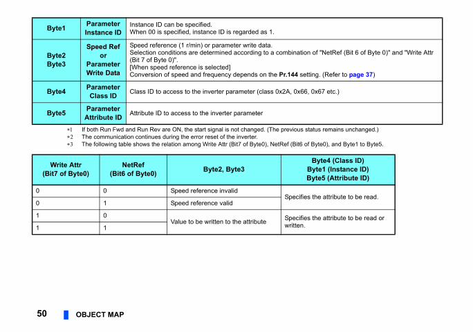
If both Run Fwd and Run Rev are ON, the start signal is not changed. (The previous sta The communication continues during the error reset of the inverter. The following table shows the relation among Write Attr (Bit7 of Byte0), NetRef (Bit6 of
Byte1 ParameterInstance ID
Instance ID can be specified.When 00 is specified, instance ID is regarded as 1.
Byte2Byte3
Speed Ref or
Parameter Write Data
Speed reference (1 r/min) or parameter write data.Selection conditions are determined according to a combination(Bit 7 of Byte 0)".[When speed reference is selected]Conversion of speed and frequency depends on the Pr.144 sett
Byte4 ParameterClass ID Class ID to access to the inverter parameter (class 0x2A, 0x66,
Byte5 ParameterAttribute ID Attribute ID to access to the inverter parameter
Write Attr(Bit7 of Byte0)
NetRef(Bit6 of Byte0) Byte2, Byte3 B
B
0 0 Speed reference invalidSpecifies
0 1 Speed reference valid
1 0Value to be written to the attribute Specifies
written.1 1

OBJECT MAP 517
2 Bit 1 Bit 0
g Runcommandmode
Faulted
is in a fault state)
: forward rotation)
: reverse rotation)
ion ready)
s Bit0 and Bit1 of Byte0.it0 and Bit1 of Byte0.
mands.nds.
ibute 3. Refer to page 75)
Input Instance 176 (inverter → master)When Input Instance 176 is used, 16 bits parameter data is provided.When using Input Instance 176, set Output Instance to 126.
• Input Instance 176 details
Byte Bit 7 Bit 6 Bit 5 Bit 4 Bit 3 Bit
0 AtReference Ref From Net Ctrl From Net Ready Running Rev
RunninFwd
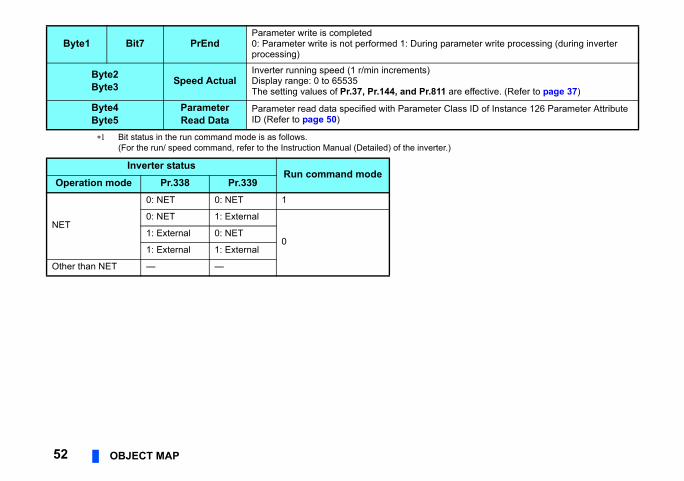
1 PrEnd Reserved (0)
2 Speed actual (low byte)
3 Speed actual (high byte)
4 Parameter read data (low byte)
5 Parameter read data (high byte)
Byte0
Bit0 Faulted Inverter fault signal(0: inverter is under normal operation 1: inverter
Bit1 Run Command Mode
0: Command is disabled in network operation1: Command is enabled in network operation
Bit2 Running Fwd Forward rotation (0: other than forward rotation 1
Bit3 Running Rev Reverse rotation (0: other than reverse rotation 1
Bit4 Ready Ready signal (0: operation preparation 1: operatAlways "1" after power ON
Bit5 CtrlFromNet 0: The inverter is set not to accept the command1: The inverter is set to accept the commands B
Bit6 RefFromNet 0: The inverter is set not to accept the speed com1: The inverter is set to accept the speed comma
Bit7 AtReference Up-to-frequency signal (SU signal)(Same definition with Class 0x2A Instance 1 Attr
rameter write processing (during inverter
are effective. (Refer to page 37)
lass ID of Instance 126 Parameter Attribute
52 OBJECT MAP
Bit status in the run command mode is as follows.(For the run/ speed command, refer to the Instruction Manual (Detailed) of the inverter.)
Byte1 Bit7 PrEndParameter write is completed0: Parameter write is not performed 1: During paprocessing)
Byte2Byte3 Speed Actual
Inverter running speed (1 r/min increments)Display range: 0 to 65535The setting values of Pr.37, Pr.144, and Pr.811
Byte4Byte5
ParameterRead Data
Parameter read data specified with Parameter CID (Refer to page 50)
Inverter statusRun command mode
Operation mode Pr.338 Pr.339
NET
0: NET 0: NET 1
0: NET 1: External
01: External 0: NET
1: External 1: External
Other than NET — —

OBJECT MAP 537
Bit 0
v Run Fwd
JOG
Format for 16-bit data (32Bit Format (Bit7 of Byte1) = 0)
Format for 32-bit data (32Bit Format (Bit7 of Byte1) = 1)
7.1.4 Output Instance 127/Input Instance 177 Output instance 127 (master → inverter)When using Output Instance 127, set Input Instance to 177.
Byte Bit 7 Bit 6 Bit 5 Bit 4 Bit 3 Bit 2 Bit 1
0 AU RT RH RM RL Fault Reset Run Re
1 32BitFormat Hz Write
Attr RES STOP MRS CS
2 Speed/frequency setting value or writing data (16 bits: L)
3 Speed/frequency setting value or writing data (16 bits: H)
4 Attribute 2 class ID (reading specified only)
5 Attribute 2 attribute ID (reading specified only)
6 Attribute 1 class ID (both reading and writing)
7 Attribute 1 attribute ID (both reading and writing)
2 Speed/frequency setting value or writing data (32 bits: LL)
3 Speed/frequency setting value or writing data (32 bits: LH)
4 Writing data (32 bits: HL)
5 Writing data (32 bits: HH)
6 Attribute 1 class ID
7 Attribute 1 attribute ID

• Output Instance 127 details
rd rotation ON)
se rotation ON)
g value. 32-bit data) are set to the data to be written
g value, the increment is 1 r/min.g value, the increment is 0.01 Hz.
54 OBJECT MAP
Byte0
Bit0 Run Fwd Forward rotation signal (0: forward rotation OFF 1: forwa
Bit1 Run Rev Reverse rotation signal (0: reverse rotation OFF 1: rever
Bit2 Fault ResetReset request at an error occurrence Valid only at in inverter trip(0: no function 1: fault reset request)
Bit3 Terminal RL Terminal RL (0: OFF 1: ON)
Bit4 Terminal RM Terminal RM (0: OFF 1: ON)
Bit5 Terminal RH Terminal RH (0: OFF 1: ON)
Bit6 Terminal RT Terminal RT (0: OFF 1: ON)
Bit7 Terminal AU Terminal AU (0: OFF 1: ON)
Byte1
Bit0 Terminal JOG Terminal JOG (0: OFF 1: ON)
Bit1 Terminal CS Terminal CS (0: OFF 1: ON)
Bit2 Terminal MRS Terminal MRS (0: OFF 1: ON)
Bit3 Terminal STOP Terminal STOP (0: OFF 1: ON)
Bit4 Terminal RES Terminal RES (0: OFF 1: ON)
Bit5 Write Attr0: Byte2 and Byte3 are set to the speed/frequency settin1: Byte2 and Byte3 (Byte2 to Byte5 for the format for theto the attribute.
Bit6 Hz 0: When Byte2 and Byte3 are the speed/frequency settin1: When Byte2 and Byte3 are the speed/frequency settin
Bit7 32Bit Format 0: The format for 16-bit data is being selected.1: The format for 32-bit data is being selected.

OBJECT MAP 557
tus remains unchanged.) Some signals are not controllable via network ES function) cannot be controlled via network
(Detailed) of the inverter.a size is 1 byte, the value set in Byte3 is invalid.. The set values in Byte4 and Byte5 are invalid.a size is 1 byte, the values set in Byte3, Byte4,
ormat for 32-bit data Format (Bit7 of Byte1) = 1)
te1) = 0, Hz (Bit6 of Byte1) = 0 (1 r/min increments) (Refer to page 37)te1) = 0, Hz (Bit6 of Byte1) = 1alue (0.01 Hz increments)
te1) = 1o the attribute specified by Byte6 and Byte7.
The communication continues during the error reset of the inverter. If both Run Fwd and Run Rev are ON, the start signal is not changed. (The previous sta Using Pr.180 to Pr.189, input signals assigned to the device numbers can be changed.
depending on the settings of Pr.338 and Pr.339. For example, Bit4 of Byte1 (terminal Rwhen Pr.189 is set to the initial value (RES signal).For the details of Pr.180 to Pr.189, Pr.338, and Pr.339, refer to the Instruction Manual
The setting value exceeding the data size of the target attribute is invalid. When the dat For the speed/frequency setting value, the set values only in Byte2 and Byte3 are valid The setting value exceeding the data size of the target attribute is invalid. When the dat
and Byte5 are invalid.
Format for 16-bit data(32Bit Format (Bit7 of Byte1) = 0)
F(32Bit
Byte2Byte3
• WriteAttr (Bit5 of Byte1) = 0, Hz (Bit6 of Byte1) = 0Speed setting value (1 r/min increments) (Refer to page 37)
• WriteAttr (Bit5 of Byte1) = 0, Hz (Bit6 of Byte1) = 1Frequency setting value (0.01 Hz increments)
• WriteAttr (Bit5 of Byte1) = 1Value to be written to the attribute specified by Byte6 and Byte7.
• WriteAttr (Bit5 of BySpeed setting value
• WriteAttr (Bit5 of ByFrequency setting v
• WriteAttr (Bit5 of ByValue to be written t
Byte4 Class ID of Attribute 2 to be read (reading only)
Byte5 Attribute ID of Attribute 2 to be read (reading only)
Byte6Class ID when Attribute 1 is read or writtenWrite Attr (Bit5 of Byte1) = 0: Reading the attributeWrite Attr (Bit5 of Byte1) = 1: Writing the attribute
Byte7Attribute ID when Attribute 1 is read or writtenWrite Attr (Bit5 of Byte1) = 0: Reading the attributeWrite Attr (Bit5 of Byte1) = 1: Writing the attribute

Bit 0
g Running Fwd
l Terminal FU
Format for 16-bit data (32Bit Format (Bit7 of Byte1) = 0)
Format for 32-bit data (32Bit Format (Bit7 of Byte1) = 1)
56 OBJECT MAP
Input Instance 177 (inverter → master)When using Input Instance 177, set Output Instance to 127.
Byte Bit 7 Bit 6 Bit 5 Bit 4 Bit 3 Bit 2 Bit 1
0 Terminal OL
Terminal IPF
Terminal SU
Terminal RUN
Run command mode
Faulted RunninRev
1 32BitFormat Hz Reserved
(0)Reserved (0)
Reserved (0)
Terminal ABC2
TerminaABC1
2 Actual speed/output frequency (16 bits: L)
3 Actual speed/output frequency (16 bits: H)
4 Attribute 1 read data (16 bits: L)
5 Attribute 1 read data (16 bits: H)
6 Attribute 2 read data (16 bits: L)
7 Attribute 2 read data (16 bits: H)
2 Actual speed/output frequency (32 bits: L)
3 Actual speed/output frequency (32 bits: H)
4 Attribute 1 read data 1 (32 bits: LL)
5 Attribute 1 read data 1 (32 bits: LH)
6 Attribute 1 read data 1 (32 bits: HL)
7 Attribute 1 read data 1 (32 bits: HH)

OBJECT MAP 577
• Input Instance 177 details
ault state)
..
Byte0
Bit0 Running Fwd Forward rotation (0: other than forward rotation 1: forward rotation)
Bit1 Running Rev Reverse rotation (0: other than reverse rotation 1: reverse rotation)
Bit2 Faulted Inverter fault signal(0: inverter is under normal operation 1: inverter is in a f
Bit3 Run command mode
0: Command is disabled in network operation1: Command is enabled in network operation
Bit4 Terminal RUN Terminal RUN (0: OFF 1: ON)
Bit5 Terminal SU Terminal SU (0: OFF 1: ON)
Bit6 Terminal IPF Terminal IPF (0: OFF 1: ON)
Bit7 Terminal OL TerminalOL (0: OFF 1: ON)
Byte1
Bit0 Terminal FU Terminal FU (0: OFF 1: ON)
Bit1 Terminal ABC1 Terminal ABC1 (0: OFF 1: ON)
Bit2 Terminal ABC2 Terminal ABC2 (0: OFF 1: ON)
Bit6 Hz 0: The increment of 1 r/min is used for Byte2 and Byte31: The increment of 0.01 Hz is used for Byte2 and Byte3
Bit7 32Bit format 0: The format for 16-bit data is being selected.1: The format for 32-bit data is being selected.
.rter.
Format for 32-bit datat Format (Bit7 of Byte1) = 1)
ttribute specified by Byte6 and Byte7 of
ted attribute is specified, 0 is returned.
58 OBJECT MAP
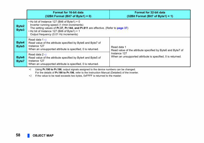
Using Pr.190 to Pr.196, output signals assigned to the device numbers can be changedFor the details of Pr.190 to Pr.196, refer to the Instruction Manual (Detailed) of the inve
If the value to be read exceeds two bytes, 0xFFFF is returned to the master.
Format for 16-bit data(32Bit Format (Bit7 of Byte1) = 0) (32Bi
Byte2Byte3
• Hz bit of Instance 127 (Bit6 of Byte1) = 0Inverter running speed (1 r/min increments)The setting values of Pr.37, Pr.144, and Pr.811 are effective. (Refer to page 37)
• Hz bit of Instance 127 (Bit6 of Byte1) = 1Output frequency (0.01 Hz increments)
Byte4Byte5
Read data 1 Read value of the attribute specified by Byte6 and Byte7 of Instance 127When an unsupported attribute is specified, 0 is returned.
Read data 1Read value of the aInstance 127When an unsupporByte6
Byte7
Read data 2 Read value of the attribute specified by Byte4 and Byte5 of Instance 127When an unsupported attribute is specified, 0 is returned.

OBJECT MAP 597
connection)
No. of data bytes Attribute value
2 1
2 1
2 7
2 7
7.2 Message communication (Explicit message
7.2.1 Class 0x01 (Identity-Object) Class 0x01 Instance 0[Attribute]
[Service]
Class 0x01 Instance 0
Attribute ID Access Definition Data type
1 Get Revision UINT
2 Get Maximum Instance UINT
6 Get Max Class Attributes UINT
7 Get Max Instance Attributes UINT
Service code Definition
0x0E Get Attribute Single

always 0, Bit 10: 1 = LED is flickering red, Bit 11:
R-A800 series.R-F800 series.
r. 75.ar will be performed.
No. of data bytes Attribute value
2 161
2 02
2 71, 73
2 1.YYY
2
4 xxxxxxxx
5 A800/F800
Descriptionrter reset
rter reset after all parameter clear
Attribute Single
60 OBJECT MAP
Class 0x01 Instance 1[Attribute]
The value indicates that the option is connected to the FR-A800 series. The value indicates that the option is connected to the FR-F800 series. High byte of hexadecimal word data means integer, and low byte means decimal.
For example, when the read data is 0x010A, it means version 1.010. Bit definition
Bit 0: 0 = allocated, 1 = not allocated, Bit 2: always 0, Bit 8: 1 = alarm occurrence, Bit 9:1 = LED is lit red
The actual data are 0x04, 0x41, 0x38, 0x30, 0x30 when the option is connected to the FThe actual data are 0x04, 0x46, 0x38, 0x30, 0x30 when the option is connected to the F0x04 means 4 byte data, and the rest means ASCII code of "A800"/"F800".
[Service]
As set in Pr. 75. Refer to the Instruction Manual (Detailed) of the inverter for details of P If the inverter does not accept the command, neither inverter reset nor all parameter cle
Class 0x01 Instance 1
Attribute ID Access Definition Data type
1 Get Vendor ID (Mitsubishi electric) UINT
2 Get Device Type (AC drive) UINT
3 Get Product Code UINT
4 Get Revision STRUCT
5 Get Status WORD
6 Get Serial Number UDINT
7 Get Product Name(FR-A800/F800) SHORT_STRING
Service code Symbol Name Setting range
0x05 Reset Reset 0 Inve
1 Inve
0x0E Get Get_Attribute_Single — Get

OBJECT MAP 617
16.) The setting value is applied to bit 0 to 5 of
Description
ode address value node address switches are set to any of "0 to lue is returned. In this case, writing (Set) is e.
ps, 01: 250 kbps, ps
Bit 0 = 1: Explicit allocation requestedBit 1 = 1: Poll allocation requestedOthers: Fixed to 0
MAC ID of the master that requests allocation.
values of the node address switches are the hose before power ON or inverter reset. values of the node address switches are ompared to the ones before power ON or set.
ode address value
7.2.2 Class 0x03 (DeviceNet Object) Class 0x03 Instance 1[Attribute]
Can be read with Class 0x67 Instance 1 Attribute 45 and 46 also. (Refer to page 88) To enable the MAC ID, set the node address switches to "64 or higher". (Refer to page
Pr.345.
Class 0x03 Instance 1
Attribute ID Access Name Data
typeNo. of
data bytesInitialvalue
1 Get/Set MAC ID USINT 1 —
00 to 63: NWhen the 63", the vaunavailabl
2 Get/Set Baud Rate USINT 1 00 00: 125 kb02: 500 kb
5 Get Allocation Information STRUCT 2 0
AllocationChoice Byte
Master's MAC ID
6 Get MAC ID Switch Changed BOOL 1 0
0: The setsame as t1: The setdifferent cinverter re
8 Get MAC ID Switch Value USINT 1 00 00 to 99: N

[Service]
62 OBJECT MAP
Service code Service
0x0E Get Attribute Single
0x10 Set Attribute Single

OBJECT MAP 637
Description
put Instance 70 of the I/O communication is
put Instance 71 of the I/O communication is
put Instance 176 of the I/O communication
put Instance 177 of the I/O communication
put Instance 70 of the I/O communication is
put Instance 71 of the I/O communication is
put Instance 176 of the I/O communication
put Instance 177 of the I/O communication
7.2.3 Class 0x04 (Assembly Object)[Attribute]
[Service]
Instance ID
Attribute ID Access Name Data type No. of
data bytes
20 3 Get Data BYTE array 4 The data of Inreturned.
21 3 Get Data BYTE array 4 The data of Inreturned.
126 3 Get Data BYTE array 6 The data of Inis returned.
127 3 Get Data BYTE array 6 The data of Inis returned.
70 3 Get Data BYTE array 4 The data of Inreturned.
71 3 Get Data BYTE array 4 The data of Inreturned.
176 3 Get Data BYTE array 6 The data of Inis returned.
177 3 Get Data BYTE array 6 The data of Inis returned.
Service code Service
0x0E Get Attribute Single

stance 4 to 6 are Explicit messaging
n)
Definition
-existent
figuring
blished
d out
licit messaging connection
: Server Transport Class 3
ID that the inverter sends
ID that the inverter receives
value defines sent and received message ps.: Both send and receive messages are p 2 message
value specifies the maximum number of sage Body bytes that a module is able to smit across the connection.byte
64 OBJECT MAP
7.2.4 Class 0x05 (DeviceNet connection object)FR-A8ND supports only Polled I/O and Explicit Msg, not Bit-Strobed I/O. In addition, InInstance. Class 0x05 Instance 1 attribute (Explicit messaging connectio
Class 0x05 Instance 1
AttributeID Access Name Data
typeNo. of
data bytes Range
1 Get State USINT 1
00 Non
01 Con
03 Esta
04 Time
2 Get Instance Type USINT 1 00 Exp
3 Get Transport Trigger class BYTE 1 00 to 0xFF 0x83
4 Get Produced Connection ID UINT 2 0 to 0xFFFF CAN
5 Get Consumed Connection ID UINT 2 0 to 0xFFFF CAN
6 Get Initial Command Characteristics BYTE 1 00 to 0xFF
Thegrou0x21Grou
7 Get Produced Connection Size UINT 2 0 to 0xFFFF
ThisMestran7: 7
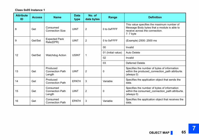
OBJECT MAP 657
value specifies the maximum number of sage Body bytes that a module is able to ive across the connection.byte
mple) 2500: 2500 ms
lid
Delete
lid
rred Delete
cifies the number of bytes of information in the produced_connection_path attriburte. ays 0)
cifies the application object that sends the .
cifies the number of bytes of information in the consumed_connection_path attriburte. ays 0)
cifies the application object that receives the .
Definition
8 Get Consumed Connection Size UINT 2 0 to 0xFFFF
ThisMesrece7: 7
9 Get/Set Expected Pack Rate(EPR) UINT 2 0 to 0xFFFF (Exa
12 Get/Set Watchdog Action USINT 1
00 Inva
01 (Initial value) Auto
02 Inva
03 Defe
13 GetProduced Connection Path Length
UINT 2 0Spewith(alw
14 Get Produced Connection Path EPATH 3 Variable Spe
data
15 GetConsumed Connection Path Length
UINT 2 0Spewith(alw
16 Get Consumed Connection Path EPATH 3 Variable Spe
data
Class 0x05 Instance 1
AttributeID Access Name Data
typeNo. of
data bytes Range

Definition
-existent
figuring
blished
d out
d I/O connection
: Server Transport Class 2
ID that the inverter sends
ID that the inverter receives
rce: Group 1 Messagetination: Group 2 Message
ber of bytes of I/O data transmittablessembly Instance 70, 71ssembly Instance 176ssembly Instance 177
ber of bytes of I/O data receivablessembly Instance 20, 21ssembly Instance 126ssembly Instance 127
mple) 2500: 2500 ms
66 OBJECT MAP
Class 0x05 Instance 2 attribute (Polled I/O connection)
Class 0x05 Instance 2Attribute
ID Access Name Data type
No. of data bytes Range
1 Get State USINT 1
00 Non
01 Con
03 Esta
04 Time
2 Get Instance Type USINT 1 01 Polle
3 Get Transport Trigger class BYTE 1 00 to 0xFF 0x82
4 Get Produced Connection ID UINT 2 0 to 0xFFFF CAN
5 Get Consumed Connection ID UINT 2 0 to 0xFFFF CAN
6 Get Initial Command Characteristics BYTE 1 00 to 0xFF Sou
Des
7 Get Produced Connection Size UINT 2 0 to 0xFFFF
Num4: A6: A8: A
8 Get Consumed Connection Size UINT 2 0 to 0xFFFF
Num4: A6: A8: A
9 Get/Set Expected Packet Rate (EPR) UINT 2 0 to 0xFFFF (Exa

OBJECT MAP 677
sition to time out
Delete
reset
lid
cifies the number of bytes of information in the produced_connection_path attriburte
value specifies Application Object of sent . , 0x34, 0x36: Assembly Instance 70, 0x34, 0x37: Assembly Instance 71, 0x42, 0x30: Assembly Instance 176, 0x42, 0x31: Assembly Instance 177
cifies the number of bytes of information in the consumed_connection_path attriburtebyte
value specifies Application Object of ived data. , 0x31, 0x34: Assembly Instance 20, 0x31, 0x35: Assembly Instance 21, 0x37, 0x45: Assembly Instance 126, 0x37, 0x46: Assembly Instance 127
Definition
12 Get/Set Watchdog Action USINT 1
0 (initial value) Tran
1 Auto
2 Auto
3 Inva
13 GetProduced Connection Path Length
UINT 2 0 to 0xFFFF Spewith
14 Get Produced Connection Path EPATH 3 00 to 0xFF
Thedata0x620x620x620x62
15 GetConsumed Connection Path Length
UINT 2 0 to 0xFFFFSpewith3: 3
16 Get Consumed Connection Path EPATH 3 00 to 0xFF
Therece0x620x620x620x62
Class 0x05 Instance 2Attribute
ID Access Name Data type
No. of data bytes Range

Since 2-byte data is sent and received for Polling I/O message communication, the lowest byte is 0x00.ct of sent and received data. The format is below.
e data
onnection Path (receive data)
0x35nection Path = 0x62 0x31 0x35
put instance value (hexadecimal).
68 OBJECT MAP
Produced Connection Path and Consumed Connection Path specifies Application Obje
(Example) When Output Instance 21 and Input Instance 71 are used as sent and receiv
For changing Input Output Assembly, refer to page 72.
Produced Connection Path (send data) Consumed C
Input Instance 71 = 0x47ASCII code: 4 = 0x34, 7 = 0x37Therefore, Produced Connection Path = 0x62 0x34 0x37
Output Instance 21 = 0x15ASCII code: 1 = 0x31, 5 =Therefore, Consumed Con
0x62 0xMM 0xNN
Logic address Application Object data. This is ASCII Code which shows input/out

OBJECT MAP 697
ection)
Definition
-existent
figuring
blished
d out
licit messaging connection
: Server Transport Class 3
ID that the inverter sends
ID that the inverter receives
value defines sent and received message ps.: Both send and receive messages are p 2 message
value specifies the maximum number of sage Body bytes that a module is able to smit across the connection.bytes
value specifies the maximum number of sage Body bytes that a module is able to ive across the connection.bytes
Class 0x05 Instance 4, 5, 6 attribute (Explicit messaging conn
Class 0x05 Instance 4, 5, 6
AttributeID Access Name Data
typeNo. of
data bytes Range
1 Get State USINT 1
00 Non
01 Con
03 Esta
04 Time
2 Get InstanceType USINT 1 00 Exp
3 Get Transport Trigger class BYTE 1 00 to 0xFF 0x83
4 Get Produced Connection ID UINT 2 0 to 0xFFFF CAN
5 Get Consumed Connection ID UINT 2 0 to 0xFFFF CAN
6 Get Initial Command Characteristics BYTE 1 00 to 0xFF
Thegrou0x33Grou
7 Get Produced Connection Size UINT 2 0 to 0xFFFF
ThisMestran7: 7
8 Get Consumed Connection Size UINT 2 0 to 0xFFFF
ThisMesrece7: 7

mple) 2500: 2500 ms
lid
Delete
rred Delete
cifies the number of bytes of information in the produced_connection_path attriburte. ays 0)
cifies the application object that sends the .
cifies the number of bytes of information in the consumed_connection_path attriburte. ays 0)
cifies the application object that receives the .
Definition
70 OBJECT MAP
Class 0x05 Instance 1, 2, 4, 5, 6 service
9 Get/Set Expected Pack Rate(EPR) UINT 2 0 to 0xFFFF (Exa
12 Get/Set Watchdog Action USINT 1
00, 02 Inva
01 (Initial value) Auto
03 Defe
13 GetProduced Connection Path Length
UINT 2 0Spewith(alw
14 Get Produced Connection Path EPATH 3 Variable Spe
data
15 GetConsumed Connection Path Length
UINT 2 0Spewith(alw
16 Get Consumed Connection Path EPATH 3 Variable Spe
data
Service code Definition
0x0E Get Attribute Single
0x10 Set Attribute Single
Class 0x05 Instance 4, 5, 6
AttributeID Access Name Data
typeNo. of
data bytes Range

OBJECT MAP 717
Definition
nduction motor
etting in 0.1 A increments. (For the FR-) or lower, FR-A840-01800(55K) or lower, 55K) or lower, FR-F840-01160(55K) or lower o one decimal place.)
Pr. 9 in 0.1 A increments.
9999" or "8888", return "200" for the 200 V for the 400 V class.0 to 1000", return the Pr. 19 setting. (decimal ded)
value ("0 to 1000, 65535 (9999), or 65520 .
7.2.5 Class 0x28 (Motor data object) Class 0x28 Instance 1[Attribute]
[Service]
Class 0x28 Instance 1
AttributeID Access Name Data
typeNo. of
data bytes Range
3 Get Motor Type USINT 1 3, 7 3: PM motor7: Squirrel-cage i
6 Get/Set Rated MotorCurrent (Pr. 9) UINT 2 0 to
0xFFFF
[GET]Return the Pr. 9 sA820-03160(55KFR-F820-02330(round the value t[SET]Write the value to
7 Get/Set Rated Voltage(Pr.19) UINT 2 0 to
0xFFFF
[GET]• When Pr. 19 = "
class and "400"• When Pr. 19 = "
places are roun[SET]Write the setting (8888)") to Pr.19
Service code Definition
0x0E Get Attribute Single
0x10 Set Attribute Single

Definition
toporward rotation topeverse rotation ther than DeviceNet
ommunication operationr.338 = 1)
Actual state of operation command can be monitored with Attribute 15.
eviceNet ommunication operationr.338 = 0)
tartupot_Ready (during reset)eady (during stop)nabled (during acceleration, during constant peed, during reverse deceleration)topping (during deceleration)ault_Stop (during deceleration with Pr. 502)aulted (during fault occurrence)
uring stop
uring forward rotation
72 OBJECT MAP
7.2.6 Class 0x29 (Control supervisor object) Class 0x29 Instance 1[Attribute]
Class 0x29 Instance 1Attribute
ID Access Name Data type
No. of data bytes
Initialvalue Range
3 Get/Set RUN1 BOOL 1 000 S1 F
4 Get/Set RUN2 BOOL 1 000 S1 R
5 Get/SetNetCtrl(operation command source) (Pr.338)
BOOL 1 1
0Oc(P
1Dc(P
6 Get State USINT 1 3
1 S2 N3 R
4 Es
5 S6 F7 F
7 GetRunning1(forward rotation command)
BOOL 1 00 D
1 D
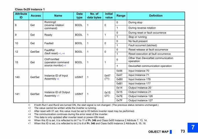
OBJECT MAP 737
tus remains unchanged.)
ed.
ribute 7, 13, 14.bute 8, 15, 16.
uring stop
uring reverse rotation
uring reset or fault occurrencetop or runningo fault presentault occurred (latched)eset release at fault occurrenceeset execution at fault occurrencether than DeviceNet communication peration
eviceNet communication operation
put Instance 70put Instance 71put Instance 176put Instance 177utput Instance 20utput Instance 21utput Instance 126utput Instance 127
Definition
If both Run1 and Run2 are turned ON, the start signal is not changed. (The previous sta The value cannot be written while the inverter is running. After reset with 01 set, this value must be set to 00 before inverter reset may be perform The communication continues during the error reset of the inverter. This data is only updated after inverter reset or power-ON reset. When this ID is set, it is reflected to bit 7 to 11 of Pr. 346 and Class 0x05 Instance 2 Att When this ID is set, it is reflected to bit 2 to 6 of Pr. 346 and Class 0x05 Instance 2 Attri
8 GetRunning2(reverse rotation command)
BOOL 1 00 D
1 D
9 Get Ready BOOL 1 10 D1 S
10 Get Faulted BOOL 1 00 N1 F
12 Get/Set FaultRst(fault reset) , BOOL 1 0
0 R1 R
15 GetCtrlFromNet(operation command source monitor)
BOOL 1 10 O
o
1 D
140 Get/Set Instance ID of Input Assembly USINT 1 0x47
(71)
0x46 In0x47 In0xB0 In0xB1 In
141 Get/SetInstance ID of Output Assembly USINT 1 0x15
(21)
0x14 O0x15 O0x7E O0x7F O
Class 0x29 Instance 1Attribute
ID Access Name Data type
No. of data bytes
Initialvalue Range

[Service]
74 OBJECT MAP
Service code Definition
0x0E Get Attribute Single
0x10 Set Attribute Single
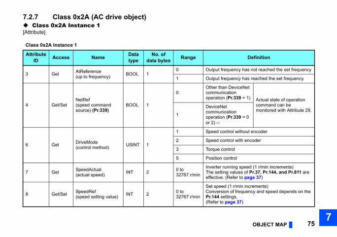
OBJECT MAP 757
Definition
requency has not reached the set frequency
requency has reached the set frequency
an DeviceNet ication n (Pr.339 = 1) Actual state of operation
command can be monitored with Attribute 29.
et ication n (Pr.339 = 0
ontrol without encoder
ontrol with encoder
control
control
running speed (1 r/min increments)ting values of Pr.37, Pr.144, and Pr.811 are . (Refer to page 37)
ed (1 r/min increments)ion of frequency and speed depends on the ettings.
o page 37)
7.2.7 Class 0x2A (AC drive object) Class 0x2A Instance 1[Attribute]
Class 0x2A Instance 1
AttributeID Access Name Data
typeNo. of
data bytes Range
3 Get AtReference(up to frequency) BOOL 1
0 Output f
1 Output f
4 Get/SetNetRef(speed command source) (Pr.339)
BOOL 1
0Other thcommunoperatio
1
DeviceNcommunoperatioor 2)
6 Get DriveMode(control method) USINT 1
1 Speed c
2 Speed c
3 Torque
5 Position
7 Get SpeedActual(actual speed) INT 2 0 to
32767 r/min
InverterThe seteffective
8 Get/Set SpeedRef(speed setting value) INT 2 0 to
32767 r/min
Set speConversPr.144 s(Refer t

put current is monitored in 0.1 A increments.
ower is monitored in 1 W increments.
put voltage is monitored in 0.1 V increments.
ation time = Pr.7 (Pr.18 / Pr.20)increments in ms regardless of the Pr.21
ation time = Pr.8 (Pr.18 / Pr.20)increments in ms regardless of the Pr.21
speed (1 r/min increments)ion of frequency and speed depends on the ettings. (Refer to page 37)
m speed (1 r/min increments)ion of frequency and speed depends on the ettings. (Refer to page 37)
an DeviceNet communication operation
et communication operation
Definition
76 OBJECT MAP
9 Get CurrentActual(output current) INT 2 0 to
3276.7 A The out
15 Get PowerActual(output power) INT 2 0 to
65535 W Output p
17 Get OutputVoltage(output voltage) INT 2 0 to
3276.7 V The out
18 Get/Set AccelTime(acceleration time) UINT 2 0 to
65535 ms
AccelerSet the setting.
19 Get/Set DecelTime(deceleration time) UINT 2 0 to
65535 ms
DecelerSet the setting.
20 Get/SetLowSpdLimit(minimum frequency) (Pr.2)
UINT 2 0 to 65535 r/min
MinimumConversPr.144 s
21 Get/SetHighSpdLimit(maximum frequency)(Pr.18)
UINT 2 0 to 65535 r/min
MaximuConversPr.144 s
29 GetRefFromNet(speed command source monitor)
BOOL 10 Other th
1 DeviceN
Class 0x2A Instance 1
AttributeID Access Name Data
typeNo. of
data bytes Range

OBJECT MAP 777
Definition
Pr. 340 to start in Network operation mode )
Communication parameters are not cleared.
Either write the set frequency to RAM or read from RAM.(0.01 Hz increments)
Write the set frequency to EEPROM(0.01 Hz increments)
mmand (Refer to page 80)
Operation mode read (Get)
tion
Operation mode write (Set) Input 2-byte data. 6)
Class 0x2A Instance 1
Attribute ID Access Data type
No. of data bytes Range
101 Set UINT 2 AnyInverter resetSet a value other than "0" in after reset. (Refer to page 27
102 Set UINT 2 0x965A Parameter clear
103 Set UINT 2 0x99AA All parameter clear 105 Set UINT 2 0x5A96 Clear parameters
106 Set UINT 2 0xAA99 All parameter clear
112 Get/Set UINT 2 0 to 0xE678 Set frequency (RAM)
113 Set UINT 2 0 to 0xE678 Set frequency (EEPROM)
114 Get/Set UINT 2 — Inverter status monitor/run co
120 Get/Set UINT 2
0 External operation
1 PU operation
2 External JOG operation
3 PU JOG operation
4 Network operation
5 External/PU combined opera
0x0010 External operation
0x0011 PU operation (when Pr. 79 =
0x0014 Network operation

efinition
)
nd Pr.811 are effective. (Refer to page 37)
factor (0.1%)A) (0.1 V)
78 OBJECT MAP
Class 0x2A Instance 1Attribute ID Access Data type No. of data bytes D
141 Get/Set UINT 2 Faults history 1 (latest)Faults history all clear
142 Get UINT 2 Faults history 2 (second fault in past)143 Get UINT 2 Faults history 3 (third fault in past)144 Get UINT 2 Faults history 4 (fourth fault in past)145 Get UINT 2 Faults history 5 (fifth fault in past)146 Get UINT 2 Faults history 6 (sixth fault in past)147 Get UINT 2 Faults history 7 (seventh fault in past148 Get UINT 2 Faults history 8 (eigth fault in past)170 Get UINT 2 Output frequency (0.01 Hz) 171 Get UINT 2 Output current (0.01 A/0.1 A) , 172 Get UINT 2 Output voltage (0.1 V) 174 Get UINT 2 Frequency setting value (0.01 Hz)
175 Get UINT 2 Running speed (1 r/min)The setting values of Pr.37, Pr.144, a
176 Get UINT 2 Motor torque (0.1%)177 Get UINT 2 Converter output voltage (0.1 V)178 Get UINT 2 Regenerative brake duty (0.1%)179 Get UINT 2 Electronic thermal relay function load180 Get UINT 2 Output current peak value (0.01 A/0.1 181 Get UINT 2 Converter output voltage peak value182 Get UINT 2 Input power (0.01 kW/0.1 kW) 183 Get UINT 2 Output power (0.01 kW/0.1 kW)
184 Get UINT 2 Input terminal status

OBJECT MAP 797
—: undetermined value)
0, —: undetermined value)
he retained values.
)
b0M RL RT AU STR STF
b0BC1 FU OL IPF SU RUN
efinition
The value cannot be written while the inverter is running. Error response is returned when the inverter will not accept the same order. The data written to Attribute 112, 113 can be read from Attribute 112. Writing any value will clear the fault records. The setting depends on the inverter capacity. Input terminal monitor details (when the terminal is ON: 1, when the terminal is OFF: 0,
Output terminal monitor details (when the terminal is ON: 1, when the terminal is OFF:
Monitoring is available only for the FR-A800 series. The monitored values are retained even if an inverter fault occurs. Resetting will clear t
185 Get UINT 2 Output terminal status 186 Get UINT 2 Load meter187 Get UINT 2 Motor excitation current (0.01 A/0.1 A188 Get UINT 2 Position pulse 189 Get UINT 2 Cumulative energization time (1 h)191 Get UINT 2 Orientation status 192 Get UINT 2 Actual operation time (1 h)193 Get UINT 2 Motor load factor (0.1%)194 Get UINT 2 Cumulative power (1 kWh)195 Get UINT 2 Position command (lower digits) 196 Get UINT 2 Position command (upper digits) 197 Get UINT 2 Current position (lower digits) 198 Get UINT 2 Current position (upper digits) 199 Get UINT 2 Droop pulse (lower digits)
b15— — — — CS RES STOP MRS JOG RH R
b15— — — — — — — — So ABC2 A
Class 0x2A Instance 1Attribute ID Access Data type No. of data bytes D

• Inverter status monitor/bit map of run command
input terminal function selection).
nd (Set)
bit Definition
RT (second function selection)
AU (current input selection)
CS (selection of automatic restart after instantaneous power failure) ,
0 MRS (output shutoff)
1 STOP (start self-holding selection)
2 RES (reset)
3 to 15 (blank)
80 OBJECT MAP
Signal names are initial values. Definitions change according to the Pr. 180 to Pr. 189 ( For the FR-F800 series, no function is assigned in the initial setting.
[Service]
Inverter status (Get) Run comma
bit Definition bit Definition
0 RUN (inverter running) 0 (blank) 7
1 FWD (during forward rotation) 1 STF (forward rotation command) 8
2 REV (during reverse rotation) 2 STR (reverse rotation command) 9
3 SU (up-to-frequency) 3 RH (high-speed operation command) 1
4 OL (overload) 4 RM (middle-speed operation command) 1
5 IPF (instantaneous power failure) 5 RL (low-speed operation
command) 1
6 FU (frequency detection) 6 JOG (JOG operation selection) 1
7 ALM (alarm)
8 to 14 (blank)
15 Operation ready completion (READY)
Service code Definition0x0E Get Attribute Single0x10 Set Attribute Single

OBJECT MAP 817
2 bytes.ed) of the inverter for details of the
is recommended. (Refer to page 90)
et/Set Starting frequency
et/Set Load pattern selection
et/Set Jog frequency
et/Set Jog acceleration/deceleration time
et/Set MRS input selection
et/Set High speed maximum frequency
et/Set Base frequency voltage
et/Set Acceleration/deceleration reference frequency
et/Set Acceleration/deceleration time increments
et/Set Stall prevention operation level(Torque limit level)
et/SetStall prevention operation level compensation factor at double speed
1
ccess Name
7.2.8 Class 0x66 (Extended object I) Class 0x66 Instance 1Set parameters of the inverter. The data type of each attribute is UINT, and the size is The usable parameters depend on the inverter. Refer to the Instruction Manual (Detailparameters.
NOTE • For parameter writing or reading, Class 0x70 to 0x79 (Extended object III)
[Attribute]
Class 0x66 Instance 1Attribute
ID Pr. Access Name
10 Pr.0 Get/Set Torque boost
11 Pr.1 Get/Set Maximum frequency
12 Pr.2 Get/Set Minimum frequency
13 Pr.3 Get/Set Base frequency
14 Pr.4 Get/Set Multi-speed setting (high speed)
15 Pr.5 Get/Set Multi-speed setting (middle speed)
16 Pr.6 Get/Set Multi-speed setting (low speed)
17 Pr.7 Get/Set Acceleration time
18 Pr.8 Get/Set Deceleration time
19 Pr.9 Get/Set Electronic thermal O/L relay
20 Pr.10 Get/Set DC injection brake operation frequency
21 Pr.11 Get/Set DC injection brake operation time
22 Pr.12 Get/Set DC injection brake operation voltage
23 Pr.13 G
24 Pr.14 G
25 Pr.15 G
26 Pr.16 G
27 Pr.17 G
28 Pr.18 G
29 Pr.19 G
30 Pr.20 G
31 Pr.21 G
32 Pr.22 G
33 Pr.23 G
Class 0x66 Instance Attribute
ID Pr. A
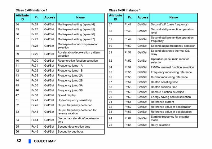
et/Set Second V/F (base frequency)
et/Set Second stall prevention operation level
et/Set Second stall prevention operation frequency
et/Set Second output frequency detection
et/Set Second electronic thermal O/L relay
et/Set Operation panel main monitor selection
et/Set FM/CA terminal function selection
et/Set Frequency monitoring reference
et/Set Current monitoring reference
et/Set Restart coasting time
et/Set Restart cushion time
et/Set Remote function selection
et/Set Energy saving control selection
et/Set Reference current
et/Set Reference value at acceleration
et/Set Reference value at deceleration
et/Set Starting frequency for elevator mode
et/Set Retry selection
1
ccess Name
82 OBJECT MAP
34 Pr.24 Get/Set Multi-speed setting (speed 4)
35 Pr.25 Get/Set Multi-speed setting (speed 5)
36 Pr.26 Get/Set Multi-speed setting (speed 6)
37 Pr.27 Get/Set Multi-speed setting (speed 7)
38 Pr.28 Get/Set Multi-speed input compensation selection
39 Pr.29 Get/Set Acceleration/deceleration pattern selection
40 Pr.30 Get/Set Regenerative function selection
41 Pr.31 Get/Set Frequency jump 1A
42 Pr.32 Get/Set Frequency jump 1B
43 Pr.33 Get/Set Frequency jump 2A
44 Pr.34 Get/Set Frequency jump 2B
45 Pr.35 Get/Set Frequency jump 3A
46 Pr.36 Get/Set Frequency jump 3B
47 Pr.37 Get/Set Speed display
51 Pr.41 Get/Set Up-to-frequency sensitivity
52 Pr.42 Get/Set Output frequency detection
53 Pr.43 Get/Set Output frequency detection for reverse rotation
54 Pr.44 Get/Set Second acceleration/deceleration time
55 Pr.45 Get/Set Second deceleration time
56 Pr.46 Get/Set Second torque boost
Class 0x66 Instance 1Attribute
ID Pr. Access Name
57 Pr.47 G
58 Pr.48 G
59 Pr.49 G
60 Pr.50 G
61 Pr.51 G
62 Pr.52 G
64 Pr.54 G
65 Pr.55 G
66 Pr.56 G
67 Pr.57 G
68 Pr.58 G
69 Pr.59 G
70 Pr.60 G
71 Pr.61 G
72 Pr.62 G
73 Pr.63 G
74 Pr.64 G
75 Pr.65 G
Class 0x66 Instance Attribute
ID Pr. A
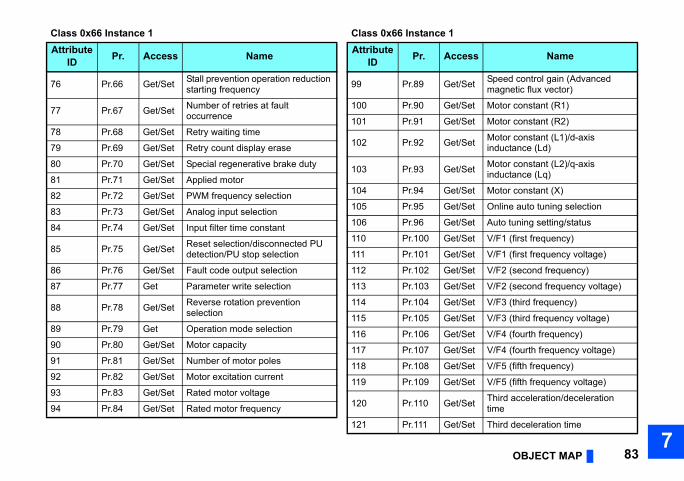
OBJECT MAP 837
et/Set Speed control gain (Advanced magnetic flux vector)
et/Set Motor constant (R1)
et/Set Motor constant (R2)
et/Set Motor constant (L1)/d-axis inductance (Ld)
et/Set Motor constant (L2)/q-axis inductance (Lq)
et/Set Motor constant (X)
et/Set Online auto tuning selection
et/Set Auto tuning setting/status
et/Set V/F1 (first frequency)
et/Set V/F1 (first frequency voltage)
et/Set V/F2 (second frequency)
et/Set V/F2 (second frequency voltage)
et/Set V/F3 (third frequency)
et/Set V/F3 (third frequency voltage)
et/Set V/F4 (fourth frequency)
et/Set V/F4 (fourth frequency voltage)
et/Set V/F5 (fifth frequency)
et/Set V/F5 (fifth frequency voltage)
et/Set Third acceleration/deceleration time
et/Set Third deceleration time
1
ccess Name
76 Pr.66 Get/Set Stall prevention operation reduction starting frequency
77 Pr.67 Get/Set Number of retries at fault occurrence
78 Pr.68 Get/Set Retry waiting time
79 Pr.69 Get/Set Retry count display erase
80 Pr.70 Get/Set Special regenerative brake duty
81 Pr.71 Get/Set Applied motor
82 Pr.72 Get/Set PWM frequency selection
83 Pr.73 Get/Set Analog input selection
84 Pr.74 Get/Set Input filter time constant
85 Pr.75 Get/Set Reset selection/disconnected PU detection/PU stop selection
86 Pr.76 Get/Set Fault code output selection
87 Pr.77 Get Parameter write selection
88 Pr.78 Get/Set Reverse rotation prevention selection
89 Pr.79 Get Operation mode selection
90 Pr.80 Get/Set Motor capacity
91 Pr.81 Get/Set Number of motor poles
92 Pr.82 Get/Set Motor excitation current
93 Pr.83 Get/Set Rated motor voltage
94 Pr.84 Get/Set Rated motor frequency
Class 0x66 Instance 1Attribute
ID Pr. Access Name
99 Pr.89 G
100 Pr.90 G
101 Pr.91 G
102 Pr.92 G
103 Pr.93 G
104 Pr.94 G
105 Pr.95 G
106 Pr.96 G
110 Pr.100 G
111 Pr.101 G
112 Pr.102 G
113 Pr.103 G
114 Pr.104 G
115 Pr.105 G
116 Pr.106 G
117 Pr.107 G
118 Pr.108 G
119 Pr.109 G
120 Pr.110 G
121 Pr.111 G
Class 0x66 Instance Attribute
ID Pr. A

et/Set PID action selection
et/Set PID proportional band
et/Set PID integral time
et/Set PID upper limit
et/Set PID lower limit
et/Set PID action set point
et/Set PID differential time
et/Set Electronic bypass sequence selection
et/Set MC switchover interlock time
et/Set Start waiting time
et/Set Bypass selection at a fault
et/Set Automatic switchover frequency from inverter to bypass operation
et/Set Backlash acceleration stopping frequency
et/Set Backlash acceleration stopping time
et/Set Backlash deceleration stopping frequency
et/Set Backlash deceleration stopping time
et/Set Speed setting switchover
et/Set PU display language selection
1
ccess Name
84 OBJECT MAP
122 Pr.112 Get/Set Third torque boost
123 Pr.113 Get/Set Third V/F (base frequency)
124 Pr.114 Get/Set Third stall prevention operation level
125 Pr.115 Get/Set Third stall prevention operation frequency
126 Pr.116 Get/Set Third output frequency detection
127 Pr.117 Get/Set PU communication station number
128 Pr.118 Get/Set PU communication speed
129 Pr.119 Get/Set PU communication stop bit length / data length
130 Pr.120 Get/Set PU communication parity check
131 Pr.121 Get/Set Number of PU communication retries
132 Pr.122 Get/Set PU communication check time interval
133 Pr.123 Get/Set PU communication waiting time setting
134 Pr.124 Get/Set PU communication CR/LF selection
135 Pr.125 Get/Set Terminal 2 frequency setting gain frequency
136 Pr.126 Get/Set Terminal 4 frequency setting gain frequency
137 Pr.127 Get/Set PID control automatic switchover frequency
Class 0x66 Instance 1Attribute
ID Pr. Access Name
138 Pr.128 G
139 Pr.129 G
140 Pr.130 G
141 Pr.131 G
142 Pr.132 G
143 Pr.133 G
144 Pr.134 G
145 Pr.135 G
146 Pr.136 G
147 Pr.137 G
148 Pr.138 G
149 Pr.139 G
150 Pr.140 G
151 Pr.141 G
152 Pr.142 G
153 Pr.143 G
154 Pr.144 G
155 Pr.145 G
Class 0x66 Instance Attribute
ID Pr. A
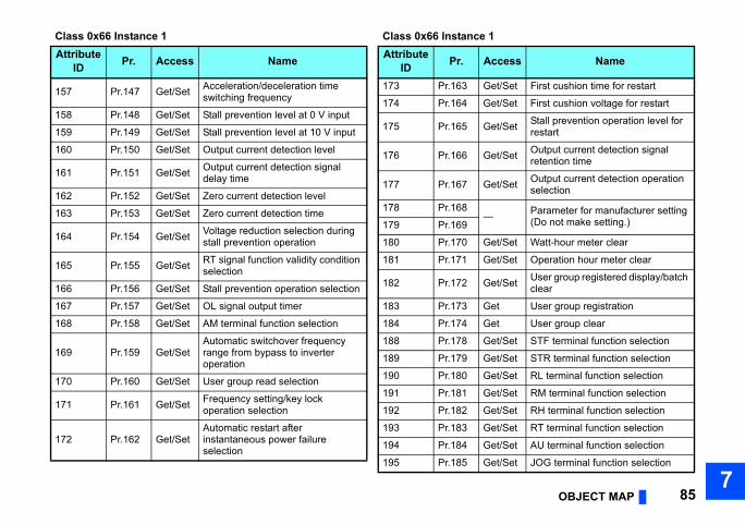
OBJECT MAP 857
et/Set First cushion time for restart
et/Set First cushion voltage for restart
et/Set Stall prevention operation level for restart
et/Set Output current detection signal retention time
et/Set Output current detection operation selection
Parameter for manufacturer setting (Do not make setting.)
et/Set Watt-hour meter clear
et/Set Operation hour meter clear
et/Set User group registered display/batch clear
et User group registration
et User group clear
et/Set STF terminal function selection
et/Set STR terminal function selection
et/Set RL terminal function selection
et/Set RM terminal function selection
et/Set RH terminal function selection
et/Set RT terminal function selection
et/Set AU terminal function selection
et/Set JOG terminal function selection
1
ccess Name
157 Pr.147 Get/Set Acceleration/deceleration time switching frequency
158 Pr.148 Get/Set Stall prevention level at 0 V input
159 Pr.149 Get/Set Stall prevention level at 10 V input
160 Pr.150 Get/Set Output current detection level
161 Pr.151 Get/Set Output current detection signal delay time
162 Pr.152 Get/Set Zero current detection level
163 Pr.153 Get/Set Zero current detection time
164 Pr.154 Get/Set Voltage reduction selection during stall prevention operation
165 Pr.155 Get/Set RT signal function validity condition selection
166 Pr.156 Get/Set Stall prevention operation selection
167 Pr.157 Get/Set OL signal output timer
168 Pr.158 Get/Set AM terminal function selection
169 Pr.159 Get/SetAutomatic switchover frequency range from bypass to inverter operation
170 Pr.160 Get/Set User group read selection
171 Pr.161 Get/Set Frequency setting/key lock operation selection
172 Pr.162 Get/SetAutomatic restart after instantaneous power failure selection
Class 0x66 Instance 1Attribute
ID Pr. Access Name
173 Pr.163 G
174 Pr.164 G
175 Pr.165 G
176 Pr.166 G
177 Pr.167 G
178 Pr.168—
179 Pr.169
180 Pr.170 G
181 Pr.171 G
182 Pr.172 G
183 Pr.173 G
184 Pr.174 G
188 Pr.178 G
189 Pr.179 G
190 Pr.180 G
191 Pr.181 G
192 Pr.182 G
193 Pr.183 G
194 Pr.184 G
195 Pr.185 G
Class 0x66 Instance Attribute
ID Pr. A

et/Set Terminal 1 added compensation amount (terminal 4)
et/Set Cooling fan operation selection
et/Set Rated slip
et/Set Slip compensation time constant
et/Set Constant-power range slip compensation selection
et/Set Earth (ground) fault detection at start
et/Set Stop selection
et/Set Output phase loss protection selection
et/Set Override bias
et/Set Override gain
et Life alarm status display
et Inrush current limit circuit life display
et Control circuit capacitor life display
et Main circuit capacitor life display
et Main circuit capacitor life measuring
et/Set PWM frequency automatic switchover
et/Set Power failure stop selection
1
ccess Name
86 OBJECT MAP
196 Pr.186 Get/Set CS terminal function selection
197 Pr.187 Get/Set MRS terminal function selection
198 Pr.188 Get/Set STOP terminal function selection
199 Pr.189 Get/Set RES terminal function selection
200 Pr.190 Get/Set RUN terminal function selection
201 Pr.191 Get/Set SU terminal function selection
202 Pr.192 Get/Set IPF terminal function selection
203 Pr.193 Get/Set OL terminal function selection
204 Pr.194 Get/Set FU terminal function selection
205 Pr.195 Get/Set ABC1 terminal function selection
206 Pr.196 Get/Set ABC2 terminal function selection
212 Pr.232 Get/Set Multi-speed setting (speed 8)
213 Pr.233 Get/Set Multi-speed setting (speed 9)
214 Pr.234 Get/Set Multi-speed setting (speed 10)
215 Pr.235 Get/Set Multi-speed setting (speed 11)
216 Pr.236 Get/Set Multi-speed setting (speed 12)
217 Pr.237 Get/Set Multi-speed setting (speed 13)
218 Pr.238 Get/Set Multi-speed setting (speed 14)
219 Pr.239 Get/Set Multi-speed setting (speed 15)
220 Pr.240 Get/Set Soft-PWM operation selection
221 Pr.241 Get/Set Analog input display unit switchover
222 Pr.242 Get/Set Terminal 1 added compensation amount (terminal 2)
Class 0x66 Instance 1Attribute
ID Pr. Access Name
223 Pr.243 G
224 Pr.244 G
225 Pr.245 G
226 Pr.246 G
227 Pr.247 G
229 Pr.249 G
230 Pr.250 G
231 Pr.251 G
232 Pr.252 G
233 Pr.253 G
235 Pr.255 G
236 Pr.256 G
237 Pr.257 G
238 Pr.258 G
239 Pr.259 G
240 Pr.260 G
241 Pr.261 G
Class 0x66 Instance Attribute
ID Pr. A

OBJECT MAP 877
0xFFF0) and 65535 (0xFFFF) respectively.
NOTE• Values "8888" and "9999" displayed on the parameter unit indicate 65520 ([Service]
242 Pr.262 Get/Set Subtracted frequency at deceleration start
243 Pr.263 Get/Set Subtraction starting frequency
244 Pr.264 Get/Set Power-failure deceleration time 1
245 Pr.265 Get/Set Power-failure deceleration time 2
246 Pr.266 Get/Set Power failure deceleration time switchover frequency
247 Pr.267 Get/Set Terminal 4 input selection
248 Pr.268 Get/Set Monitor decimal digits selection
249 Pr.269 — Parameter for manufacturer setting (Do not make setting.)
Service code Definition
0x0E Get Attribute Single
0x10 Set Attribute Single
Class 0x66 Instance 1Attribute
ID Pr. Access Name

2 bytes.ed) of the inverter of the parameters.
is recommended. (Refer to page 90)
Get/Set Brake operation frequencyGet/Set Brake operation time at stop
Get/Set Deceleration detection function selection
Get/SetOverspeed detection frequency(Speed deviation excess detection frequency)
Get/Set Droop gainGet/Set Droop filter time constant
Get/Set Communication operation command source
Get/Set Communication speed command source
Get/Set Communication startup mode selection
Get/Set RS-485 communication CR/LF selection
Get/Set Communication EEPROM write selection
1
Access Name
88 OBJECT MAP
7.2.9 Class 0x67 (Extended object II) Class 0x67 Instance 1Set parameters of the inverter. The data type of each attribute is UINT, and the size is The usable parameters depend on the inverter. Refer to the instruction manual (Detail
NOTE • For parameter writing or reading, Class 0x70 to 0x79 (Extended object III)
[Attribute]
Class 0x67 Instance 1Attribute
ID Pr. Access Name
10 Pr.270 Get/Set Stop-on contact/load torque high-speed frequency control selection
11 Pr.271 Get/Set High-speed setting maximum current
12 Pr.272 Get/Set Middle-speed setting minimum current
13 Pr.273 Get/Set Current averaging range
14 Pr.274 Get/Set Current averaging filter time constant
15 Pr.275 Get/Set Stop-on contact excitation current low-speed multiplying factor
16 Pr.276 Get/Set PWM carrier frequency at stop-on contact
18 Pr.278 Get/Set Brake opening frequency19 Pr.279 Get/Set Brake opening current
20 Pr.280 Get/Set Brake opening current detection time
21 Pr.281 Get/Set Brake operation time at start
22 Pr.28223 Pr.283
24 Pr.284
25 Pr.285
26 Pr.28627 Pr.287
38 Pr.338
39 Pr.339
40 Pr.340
41 Pr.341
42 Pr.342
Class 0x67 Instance Attribute
ID Pr.

OBJECT MAP 897
0xFFF0) and 65535 (0xFFFF) respectively.
Get/Set Terminal 2 frequency setting gain frequency
Get/Set Terminal 2 frequency setting gain
Get/Set Terminal 4 frequency setting bias frequency
Get/Set Terminal 4 frequency setting bias
Get/Set Terminal 4 frequency setting gain frequency
Get/Set Terminal 4 frequency setting gain
1
Access Name
NOTE • Values "8888" and "9999" displayed on the parameter unit indicate 65520 (
[Service]
45 Pr.345 Get DeviceNet address46 Pr.346 Get DeviceNet baud rate67 Pr.367 Get/Set Speed feedback range68 Pr.368 Get/Set Feedback gain
192 Pr.500 Get/Set Communication error execution waiting time
193 Pr.501 Get/Set Communication error occurrence count display
194 Pr.502 Get/Set Stop mode selection at communication error
202 C2(Pr.902) Get/Set Terminal 2 frequency setting bias
frequency
203 C3(Pr.902) Get/Set Terminal 2 frequency setting bias
Class 0x67 Instance 1Attribute
ID Pr. Access Name
204 Pr.125(Pr.903)
205 C4(Pr.903)
206 C5(Pr.904)
207 C6(Pr.904)
208 Pr.126(Pr.905)
209 C7(Pr.905)
Class 0x67 Instance Attribute
ID Pr.
Service code Definition
0x0E Get Attribute Single
0x10 Set Attribute Single

r for details of the parameters.
Definition
Parameter offset for calibration, gain
Analog value of calibration parameter
90 OBJECT MAP
7.2.10 Class 0x70 to 0x79 (Extended object III) Class 0x70 to 0x79 Instance 1, 2Set parameters of the inverter. Refer to the Instruction Manual (Detailed) of the inverte[Attribute]
[Service]
Class 0x70 to 0x79 Instance 1, 2
Class Instance Attribute Pr. Access Data type
Number of bytes
0x70 1 10 to 109 Pr.0 to Pr.99 Get/Set UINT 2
0x71 1 10 to 109 Pr.100 to Pr.199 Get/Set UINT 2
0x72 1 10 to 109 Pr.200 to Pr.299 Get/Set UINT 2
0x73 1 10 to 109 Pr.300 to Pr.399 Get/Set UINT 2
0x74 1 10 to 109 Pr.400 to Pr.499 Get/Set UINT 2
0x75 1 10 to 109 Pr.500 to Pr.599 Get/Set UINT 2
0x76 1 10 to 109 Pr.600 to Pr.699 Get/Set UINT 2
0x77 1 10 to 109 Pr.700 to Pr.799 Get/Set UINT 2
0x78 1 10 to 109 Pr.800 to Pr.899 Get/Set UINT 2
0x791 10 to 109 Pr.900 to Pr.999 Get/Set UINT 2
2 10 to 49 Pr.900 to Pr.939 Get/Set UINT 2
Service code Definition
0x0E Get Attribute Single
0x10 Set Attribute Single

OBJECT MAP 917
size is 2 bytes.etailed) of the inverter for the details of
osition pulse —umulative energization me 1 h
rientation status —ctual operation time 1 hotor load factor 0.1%umulative power 1 kWhosition command
lower digits) 1
osition command upper digits) 1
urrent position lower digits) 1
urrent position upper digits) 1
roop pulse lower digits) 1
roop pulse upper digits) 1
orque command 0.1%orque current command 0.1%
1
Definition Unit
7.2.11 Class 0x80 (Extended object IV) Class 0x80 Instance 1Inverter monitored value can be read. The data type of each attribute is UINT, and theThe readable monitor items depend on the inverter. Refer to the Instruction Manual (Deach monitor.[Attribute]
Class 0x80 Instance 1Attribute
ID Access Definition Unit
11 Get Output frequency , 0.01 Hz 12 Get Output current 0.01 A/0.1 A 13 Get Output voltage 0.1 V15 Get Frequency setting 0.01 Hz
16 Get Running speed 1 r/min
17 Get Motor torque 0.1%18 Get Converter output voltage 0.1 V19 Get Regenerative brake duty 0.1%
20 Get Electronic thermal relay function load factor 0.1%
21 Get Output current peak value 0.01 A/0.1 A
22 Get Converter output voltage peak value 0.1 V
23 Get Input power 0.01 kW/0.1 kW
24 Get Output power 0.01 kW/0.1 kW
25 Get Input terminal status —26 Get Output terminal status —27 Get Load meter 0.1%28 Get Motor excitation current 0.01 A/0.1 A
29 Get P
30 Get Cti
32 Get O33 Get A34 Get M35 Get C
36 Get P(
37 Get P(
38 Get C(
39 Get C(
40 Get D(
41 Get D(
42 Get T43 Get T
Class 0x80 Instance Attribute
ID Access
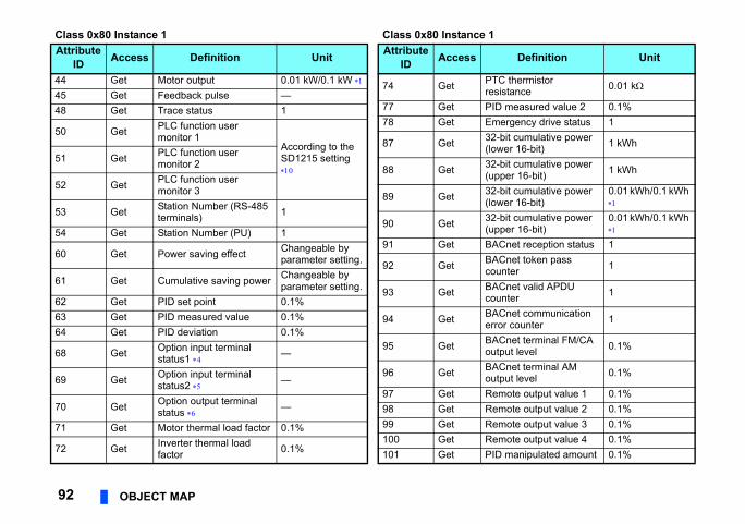
TC thermistor esistance 0.01 k
ID measured value 2 0.1%mergency drive status 12-bit cumulative power lower 16-bit) 1 kWh
2-bit cumulative power upper 16-bit) 1 kWh
2-bit cumulative power lower 16-bit)
0.01 kWh/0.1 kWh
2-bit cumulative power upper 16-bit)
0.01 kWh/0.1 kWh
ACnet reception status 1ACnet token pass ounter 1
ACnet valid APDU ounter 1
ACnet communication rror counter 1
ACnet terminal FM/CA utput level 0.1%
ACnet terminal AM utput level 0.1%
emote output value 1 0.1%emote output value 2 0.1%emote output value 3 0.1%emote output value 4 0.1%ID manipulated amount 0.1%
1
Definition Unit
92 OBJECT MAP
44 Get Motor output 0.01 kW/0.1 kW 45 Get Feedback pulse —48 Get Trace status 1
50 Get PLC function user monitor 1
According to the SD1215 setting
51 Get PLC function user monitor 2
52 Get PLC function user monitor 3
53 Get Station Number (RS-485 terminals) 1
54 Get Station Number (PU) 1
60 Get Power saving effect Changeable by parameter setting.
61 Get Cumulative saving power Changeable by parameter setting.
62 Get PID set point 0.1%63 Get PID measured value 0.1%64 Get PID deviation 0.1%
68 Get Option input terminal status1 —
69 Get Option input terminal status2 —
70 Get Option output terminal status —
71 Get Motor thermal load factor 0.1%
72 Get Inverter thermal load factor 0.1%
Class 0x80 Instance 1Attribute
ID Access Definition Unit
74 Get Pr
77 Get P78 Get E
87 Get 3(
88 Get 3(
89 Get 3(
90 Get 3(
91 Get B
92 Get Bc
93 Get Bc
94 Get Be
95 Get Bo
96 Get Bo
97 Get R98 Get R99 Get R100 Get R101 Get P
Class 0x80 Instance Attribute
ID Access

OBJECT MAP 937
102 Get Second PID set point 0.1%
103 Get Second PID measured value 0.1%
104 Get Second PID deviation 0.1%
105 Get Second PID measured value 2 0.1%
106 Get Second PID manipulated amount 0.1%
107 Get Dancer main speed setting 0.01 Hz
108 Get Control circuit temperature 1°C
Class 0x80 Instance 1Attribute
ID Access Definition Unit

The setting depends on the inverter capacity. ─: undetermined value)
0, ─: undetermined value)
erminal is ON: 1, when the terminal is OFF: 0, ─:
erminal is ON: 1, when the terminal is OFF: 0, ─:
n the terminal is ON: 1, when the terminal is OFF:
tored when Pr.430 ≠ "9999".to the Instruction Manual (Detailed) of the inverter
he retained values.
b0RL RT AU STR STF
b0C1 FU OL IPF SU RUN
b0X4 X3 X2 X1 X0
b0─ ─ ─ ─ DY
b0Y4 Y3 Y2 Y1 Y0
94 OBJECT MAP
Input terminal monitor details (when the terminal is ON: 1, when the terminal is OFF: 0,
Output terminal monitor details (when the terminal is ON: 1, when the terminal is OFF:
Details of option input terminal monitor 1 (input terminal status of FR-A8AX (when the tundetermined value)). ─all terminals are off when an option is not fitted.
Details of option input terminal monitor 2 (input terminal status of FR-A8AX (when the tundetermined value)). ─all terminals are off when an option is not fitted.
Details of option output terminal monitor (output terminal status of FR-A8AY/A8AR (whe0, ─: undetermined value)). ─all terminals are off when an option is not fitted.
When position control is selected for the FR-A800 series, the number of pulses is moni Regardless of the Pr. 37 setting, the value is always displayed in frequency (Hz). Refer
for the details. The monitored values are retained even if an inverter fault occurs. Resetting will clear t For the details, refer to the PLC Function Programming Manual. The setting values of Pr.37, Pr.144, and Pr.811 are effective. (Refer to page 37)
[Service]
b15─ ─ ─ ─ CS RES STOP MRS JOG RH RM
b15─ ─ ─ ─ ─ ─ ─ ─ So ABC2 AB
b15X15 X14 X13 X12 X11 X10 X9 X8 X7 X6 X5
b15─ ─ ─ ─ ─ ─ ─ ─ ─ ─ ─
b15─ ─ ─ ─ ─ ─ RA3 RA2 RA1 Y6 Y5
Service code Definition
0x0E Get Attribute Single

OBJECT MAP 957
. Refer to the Instruction Manual
Definition
7.2.12 Class 0x90 to 0x94 (Extended object V) Class 0x90 to 0x94 Instance 1Set parameters of the inverter. The parameters that can be set depend on the inverter(Detailed) of the inverter for details of the parameters.[Attribute]
Class 0x90 to 0x94 Instance 1
Class Instance Attribute Pr. Access Data type
Numberof bytes
0x90 1 10 to 109 Pr.1000 to Pr.1099 Get/Set UINT 2
0x91 1 10 to 109 Pr.1100 to Pr.1199 Get/Set UINT 2
0x92 1 10 to 109 Pr.1200 to Pr.1299 Get/Set UINT 2
0x93 1 10 to 109 Pr.1300 to Pr.1399 Get/Set UINT 2
0x94 1 10 to 109 Pr.1400 to Pr.1499 Get/Set UINT 2

ith the FR-A5ND specification.
ot change the setting while the power is
the inverter ill switch to and 2 are set 1 2
ON
96 OBJECT MAP
7.3 FR-A5ND compatible modeSwitching to the FR-A5ND compatible mode enables the DeviceNet communication w
Switching procedure to the FR-A5ND compatible mode
NOTE • Set the compatible mode switch before switching ON the inverter and do n
ON. Otherwise you may get an electric shock. • Do not turn ON the switch 2 of the compatible mode switch.
Compatible mode switchTurning on switch 1 and off switch 2 whenpower is off, then turning on the inverter wthe FR-A5ND compatible mode. (Switch 1to OFF in the initial status.)V+C+SLDC-V-
09
87 6 5 4
321
09
87 6 5 4
321
X10
X1
ON
1 2
MNS

OBJECT MAP 977
e normal mode.
Normal mode(FR-A8ND)
Referto page
to et s
The value cannot be written to Pr.345 when "0 to 63" is set for the node address switches.
61
─
0.1 A increments
71Read from/write to Pr.19
1 V increments
─
When the operation command source is set to communication, the values cannot be written while the inverter is running.
72
─
(: Available, : Not available)
Specifications of the FR-A5ND compatible modeThe table below shows the differences between the FR-A5ND compatible mode and thRefer to the FR-A5ND manuals for details of each function of compatible mode.
ClassID
InstanceID
AttributeID Name FR-A5ND
compatible mode
0x03 1 1 Node address setting (MAC ID)
The value can be written Pr.345 regardless of the svalues of the node addresswitches.
0x03 1 3 Bus-off interrupt
0x03 1 4 Bus-off counter
0x28 1 6 Rated current (Pr.9) 0.01 A/0.1 A increments
0x28 1 7 Rated voltageRead from/write to Pr.83
0.1 V increments
0x28 1 8 Motor capacity (Pr.80)
0x28 1 9 Rated frequency (Pr.84)
0x28 1 12 Number of motor poles (Pr.144)
0x28 1 15 Base speed (Pr.3)
0x29 1 5 NetCtrl (operation command source)
The value can be written during inverter running.
0x29 1 16 DeviceNet error mode
0x29 1 40 Input assembly

(: Available, : Not available)
─
When the speed command source is set to communication, the values cannot be written while the inverter is running.
75
0.1 A increments
1 V increments
/ Period of time from 0 to reach Pr.18 High speed maximum frequency 1 ms increments
STOP and RES are available
Communication continues45, 47, 49, 53, 73
Write is not available. 72
The previous status of the start signal is held even though the forward rotation command and reverse rotation command are simultaneously turned ON.
47, 49, 53, 72
Normal mode(FR-A8ND)
Referto page
98 OBJECT MAP
Differ according to capacities.
0x29 1 41 Output assembly
0x2A 1 4 NetRef (speed command source)
The value can be written while the inverter is running.
0x2A 1 9 Actual current 0.01 A/0.1 A increments
0x2A 1 17 Output voltage 0.1 V increments
0x2A 1 18 Acceleration time Period of time from 0 to reach Pr.20 Accelerationdeceleration reference frequency (Pr.7, Pr.8)0.1 s increments
0x2A 1 19 Deceleration time
0x2A 1 114 Run command (Set) STOP and RES are not available
Communication status at error reset by the Fault Reset bit of the DeviceNet communication or by Class 0x29 Instance 1 Attribute 12 Communication stops
Writing to Class 0x29 Instance 1 Attribute 5 (NetCtrl) during inverter running Write is available.
Operation when both STF and STR are simultaneously turned ON through the DeviceNet communication(Forward rotation command and the reverse rotation command of the I/O communication or Run1 and Run2 of Class 0x29)
Inverter stop by simultaneously turning ONthe forward rotation command and reverse rotation command
ClassID
InstanceID
AttributeID Name FR-A5ND
compatible mode

APPENDIX 99
mpatible mode).
configuration software is used. roper installation of the EDS file.
APPENDIX
Appendix 1 EDS fileEDS file can be downloaded from the web site.Download the EDS file that supports the mode to be used (nomal mode / FR-A5ND co(Refer to page 96 for the mode switchover.)
Mitsubishi Electric FA Sitewww.MitsubishiElectric.co.jp/fa
The download is free.
Contact your sales representative for details.
NOTE • The EDS file has been constructed to ODVA standards on condition that a
Consult your DeviceNet configuration software instruction manual for the p
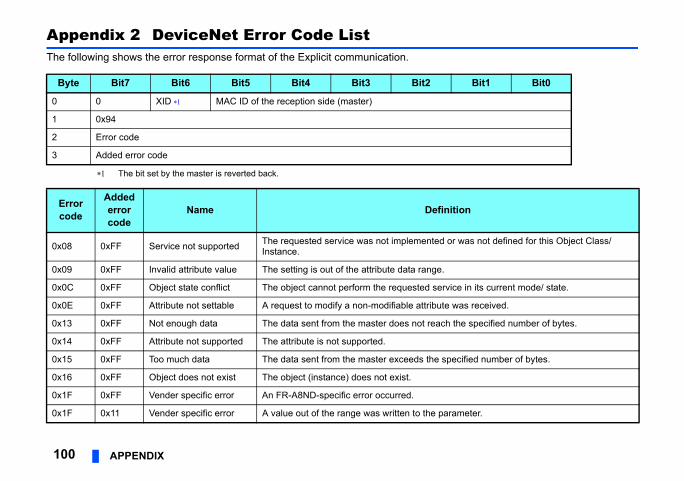
Bit1 Bit0
ition
r was not defined for this Object Class/
ice in its current mode/ state.
was received.
the specified number of bytes.
ecified number of bytes.
rameter.
100 APPENDIX
Appendix 2 DeviceNet Error Code ListThe following shows the error response format of the Explicit communication.
The bit set by the master is reverted back.
Byte Bit7 Bit6 Bit5 Bit4 Bit3 Bit2
0 0 XID MAC ID of the reception side (master)
1 0x94
2 Error code
3 Added error code
Errorcode
Added error code
Name Defin
0x08 0xFF Service not supported The requested service was not implemented oInstance.
0x09 0xFF Invalid attribute value The setting is out of the attribute data range.
0x0C 0xFF Object state conflict The object cannot perform the requested serv
0x0E 0xFF Attribute not settable A request to modify a non-modifiable attribute
0x13 0xFF Not enough data The data sent from the master does not reach
0x14 0xFF Attribute not supported The attribute is not supported.
0x15 0xFF Too much data The data sent from the master exceeds the sp
0x16 0xFF Object does not exist The object (instance) does not exist.
0x1F 0xFF Vender specific error An FR-A8ND-specific error occurred.
0x1F 0x11 Vender specific error A value out of the range was written to the pa

APPENDIX 101
s not in NET operation mode, it did not have ing.
ecified.
g, running frequency setting, etc.
ition
0x1F 0x12 Vender specific error A parameter was written when the inverter wathe operation command source, or it was runn
0x1F 0x13 Vender specific error An instruction code that does not exist was sp
0x1F 0x14 Vender specific error Invalid data was specified for parameter writin
Errorcode
Added error code
Name Defin

102 IB(NA)-0600511ENG-B
REVISIONS*The manual number is given on the bottom left of the back cover.
Print Date *Manual Number Revision
Oct. 2013 IB(NA)-0600511ENG-A First edition
Oct. 2014 IB(NA)-0600511ENG-B Addition• Compatibility with the FR-F800 series

FR-A8ND INSTRUCTION M
ANUAL
B
INV
ER
TER
INVERTERPlug-in option
INSTRUCTION MANUAL
INVERTER
PRE-OPERATION INSTRUCTIONS 1INSTALLATION 2WIRING 3INVERTER SETTING 4FUNCTIONS 5OBJECT MAP DEFINITIONS 6OBJECT MAP 7
FR-A8ND
communication function
IB(NA)-0600511ENG-B(1410) MEE Printed in Japan Specifications subject to change without notice.
HEAD OFFICE: TOKYO BUILDING 2-7-3, MARUNOUCHI, CHIYODA-KU, TOKYO 100-8310, JAPAN


