![16.0 Compozitia [Final] 2](https://static.fdocuments.net/doc/165x107/55cf921a550346f57b939e3c/160-compozitia-final-2.jpg)
Please read and save these instructions. maintain the ... · Driver data is subject to change...
66
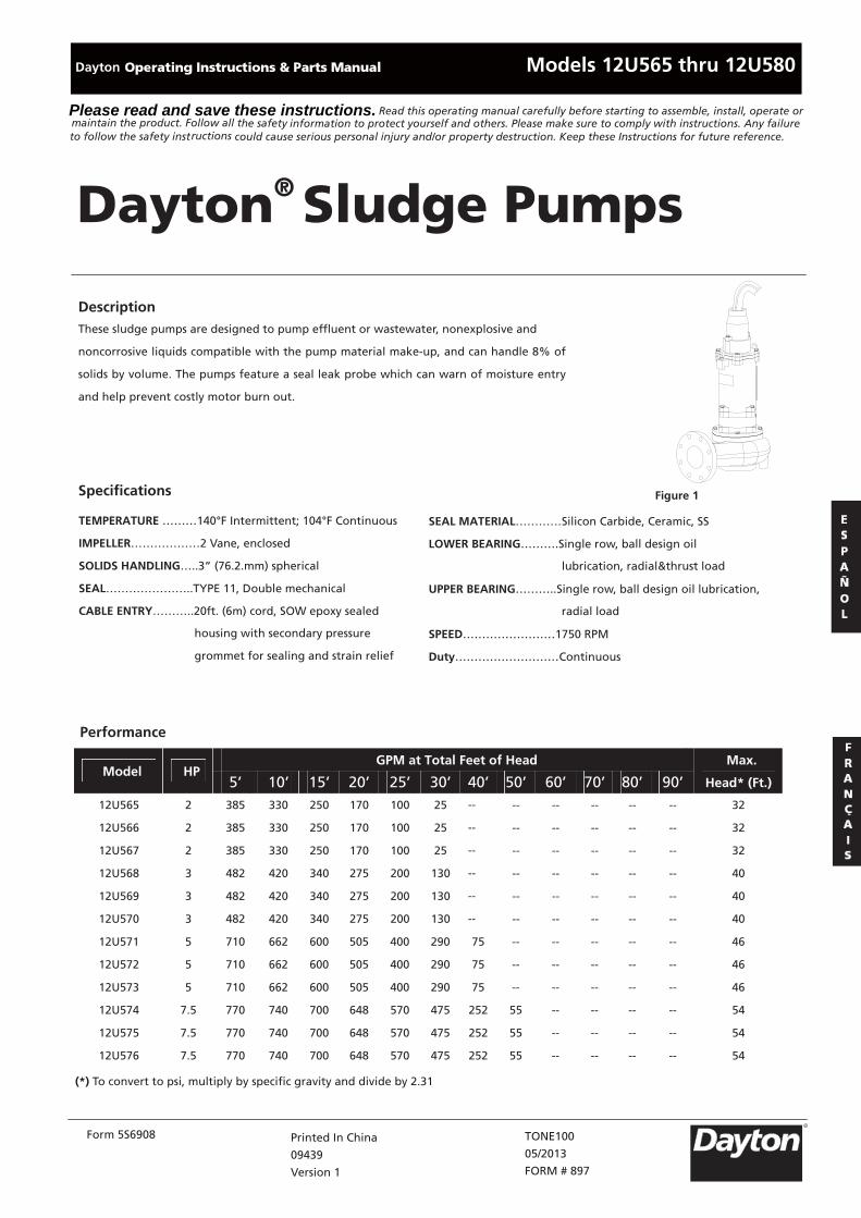
TEMPERATURE ………140°F Intermittent; 104°F Continuous IMPELLER………………2 Vane, enclosed SOLIDS HANDLING…..3” (76.2.mm) spherical SEAL…………………..TYPE 11, Double mechanical CABLE ENTRY………..20ft. (6m) cord, SOW epoxy sealed housing with secondary pressure grommet for sealing and strain relief SEAL MATERIAL…………Silicon Carbide, Ceramic, SS LOWER BEARING……….Single row, ball design oil lubrication, radial&thrust load UPPER BEARING………..Single row, ball design oil lubrication, radial load SPEED……………………1750 RPM Duty………………………Continuous Form 5S6908 Printed In China 09439 Version 1 TONE100 05/2013 FORM # 897 Models 12U565 thru 12U580 Read this operating manual carefully before starting to assemble, install, operate or he safety information to protect yourself and others. Please make sure to comply with instructions. Any failure ructions could cause serious personal injury and/or property destruction. Keep these Instructions for future reference. Dayton ® Sludge Pumps Description These sludge pumps are designed to pump effluent or wastewater, nonexplosive and noncorrosive liquids compatible with the pump material make-up, and can handle 8% of solids by volume. The pumps feature a seal leak probe which can warn of moisture entry and help prevent costly motor burn out. Figure 1 Performance Specifications GPM at Total Feet of Head Model HP 5’ 10’ 15’ 20’ 25’ 30’ 40’ 50’ 60’ 70’ 80’ 90’ Max. Head* (Ft.) 12U565 2 385 330 250 170 100 25 -- -- -- -- -- -- 32 12U566 2 385 330 250 170 100 25 -- -- -- -- -- -- 32 12U567 2 385 330 250 170 100 25 -- -- -- -- -- -- 32 12U568 3 482 420 340 275 200 130 -- -- -- -- -- -- 40 12U569 3 482 420 340 275 200 130 -- -- -- -- -- -- 40 12U570 3 482 420 340 275 200 130 -- -- -- -- -- -- 40 12U571 5 710 662 600 505 400 290 75 -- -- -- -- -- 46 12U572 5 710 662 600 505 400 290 75 -- -- -- -- -- 46 12U573 5 710 662 600 505 400 290 75 -- -- -- -- -- 46 12U574 7.5 770 740 700 648 570 475 252 55 -- -- -- -- 54 12U575 7.5 770 740 700 648 570 475 252 55 -- -- -- -- 54 12U576 7.5 770 740 700 648 570 475 252 55 -- -- -- -- 54 (*) To convert to psi, multiply by specific gravity and divide by 2.31 to follow the safety inst maintain the product. Follow all t Please read and save these instructions. R Dayton
Transcript of Please read and save these instructions. maintain the ... · Driver data is subject to change...
TEMPERATURE ………140°F Intermittent; 104°F Continuous
IMPELLER………………2 Vane, enclosed
SOLIDS HANDLING…..3” (76.2.mm) spherical
SEAL…………………..TYPE 11, Double mechanical
CABLE ENTRY………..20ft. (6m) cord, SOW epoxy sealed
housing with secondary pressure
grommet for sealing and strain relief
SEAL MATERIAL…………Silicon Carbide, Ceramic, SS
LOWER BEARING……….Single row, ball design oil
lubrication, radial&thrust load
UPPER BEARING………..Single row, ball design oil lubrication,
radial load
SPEED……………………1750 RPM
Duty………………………Continuous
Form 5S6908 Printed In China
09439
Version 1
TONE100
05/2013
FORM # 897
Models 12U565 thru 12U580
Read this operating manual carefully before starting to assemble, install, operate orhe safety information to protect yourself and others. Please make sure to comply with instructions. Any failure
ructions could cause serious personal injury and/or property destruction. Keep these Instructions for future reference.
Dayton® Sludge Pumps
Description These sludge pumps are designed to pump effluent or wastewater, nonexplosive and
noncorrosive liquids compatible with the pump material make-up, and can handle 8% of
solids by volume. The pumps feature a seal leak probe which can warn of moisture entry
and help prevent costly motor burn out.
Figure 1
Performance
Specifications
GPM at Total Feet of Head Model HP
5’ 10’ 15’ 20’ 25’ 30’ 40’ 50’ 60’ 70’ 80’ 90’
Max.
Head* (Ft.)
12U565 2 385 330 250 170 100 25 -- -- -- -- -- -- 32
12U566 2 385 330 250 170 100 25 -- -- -- -- -- -- 32
12U567 2 385 330 250 170 100 25 -- -- -- -- -- -- 32
12U568 3 482 420 340 275 200 130 -- -- -- -- -- -- 40
12U569 3 482 420 340 275 200 130 -- -- -- -- -- -- 40
12U570 3 482 420 340 275 200 130 -- -- -- -- -- -- 40
12U571 5 710 662 600 505 400 290 75 -- -- -- -- -- 46
12U572 5 710 662 600 505 400 290 75 -- -- -- -- -- 46
12U573 5 710 662 600 505 400 290 75 -- -- -- -- -- 46
12U574 7.5 770 740 700 648 570 475 252 55 -- -- -- -- 54
12U575 7.5 770 740 700 648 570 475 252 55 -- -- -- -- 54
12U576 7.5 770 740 700 648 570 475 252 55 -- -- -- -- 54
(*) To convert to psi, multiply by specific gravity and divide by 2.31
to follow the safety instmaintain the product. Follow all tPlease read and save these instructions.
R
Dayton
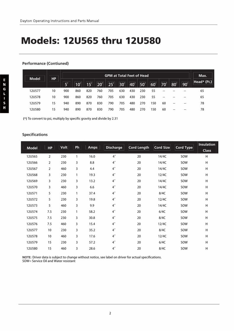
Driver data is subject to change without notice, see label on driver for actual specifications.
12U565 2 230 1 16.0 4”
12U580 15 460 3 28.6 4”
12U579 15 230 3 57.2 4”
12U578 10 460 3 17.6 4”
12U577 10 230 3 35.2 4”
12U576 7.5 460 3 15.4 4”
12U575 7.5 230 3 30.8 4”
12U574 7.5 230 1 58.2 4”
12U573 5 460 3 9.9 4”
12U572 5 230 3 19.8 4”
12U566 2 230 3 8.8 4”
12U567 2 460 3 4.4 4”
12U571 5 230 1 37.4 4”
12U570 3 460 3 6.6 4”
12U569 3 230 3 13.2 4”
12U568 3 230 1 19.3 4”
Volt Ph Amps Discharge Cord Length Cord Size Cord Type Insulation
Class
20 14/4C SOW H
20 14/4C SOW H
20 14/4C SOW H
20 12/4C SOW H
20 14/4C SOW H
20 14/4C SOW H
20 8/4C SOW H
20 12/4C SOW H
20 14/4C SOW H
20 6/4C SOW H
20 8/4C SOW H
20 12/4C SOW H
20 8/4C SOW H
20 12/4C SOW H
20 6/4C SOW H
20 8/4C SOW H
Specifications
2
Performance (Contiuned)
GPM at Total Feet of Head Model HP
5’ 10’ 15’ 20’ 25’ 30’ 40’ 50’ 60’ 70’ 80’ 90’
Max.
Head* (Ft.)
12U577 10 900 860 820 760 705 630 430 230 55 -- -- -- 65
12U578 10 900 860 820 760 705 630 430 230 55 -- -- -- 65
12U579 15 940 890 870 830 790 705 480 270 150 60 -- -- 78
12U580 15 940 890 870 830 790 705 480 270 150 60 -- -- 78
(*) To convert to psi, multiply by specific gravity and divide by 2.31
NOTE: SOW= Service Oil and Water resistant
Models: 12U565 thru 12U580
Model HP
Dayton® Sludge Pumps
3
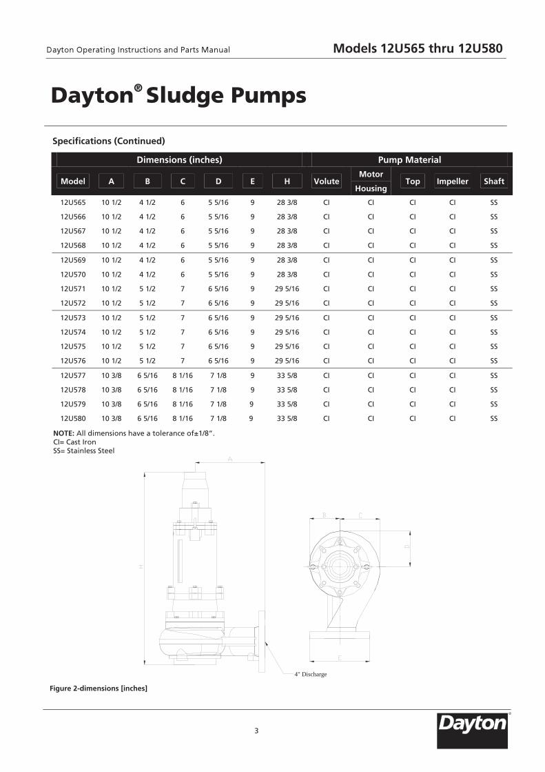
Specifications (Continued)
Figure 2-dimensions [inches]
4" Discharge
Dimensions (inches) Pump Material
Model A B C D E H VoluteMotor
Housing Top Impeller Shaft
12U565 10 1/2 4 1/2 6 5 5/16 9 28 3/8 CI CI CI CI SS
12U566 10 1/2 4 1/2 6 5 5/16 9 28 3/8 CI CI CI CI SS
12U567 10 1/2 4 1/2 6 5 5/16 9 28 3/8 CI CI CI CI SS
12U568 10 1/2 4 1/2 6 5 5/16 9 28 3/8 CI CI CI CI SS
12U569 10 1/2 4 1/2 6 5 5/16 9 28 3/8 CI CI CI CI SS
12U570 10 1/2 4 1/2 6 5 5/16 9 28 3/8 CI CI CI CI SS
12U571 10 1/2 5 1/2 7 6 5/16 9 29 5/16 CI CI CI CI SS
12U572 10 1/2 5 1/2 7 6 5/16 9 29 5/16 CI CI CI CI SS
12U573 10 1/2 5 1/2 7 6 5/16 9 29 5/16 CI CI CI CI SS
12U574 10 1/2 5 1/2 7 6 5/16 9 29 5/16 CI CI CI CI SS
12U575 10 1/2 5 1/2 7 6 5/16 9 29 5/16 CI CI CI CI SS
12U576 10 1/2 5 1/2 7 6 5/16 9 29 5/16 CI CI CI CI SS
12U577 10 3/8 6 5/16 8 1/16 7 1/8 9 33 5/8 CI CI CI CI SS
12U578 10 3/8 6 5/16 8 1/16 7 1/8 9 33 5/8 CI CI CI CI SS
12U579 10 3/8 6 5/16 8 1/16 7 1/8 9 33 5/8 CI CI CI CI SS
12U580 10 3/8 6 5/16 8 1/16 7 1/8 9 33 5/8 CI CI CI CI SS
NOTE: All dimensions have a tolerance of±1/8”. CI= Cast Iron SS= Stainless Steel
Models 12U565 thru 12U580
R
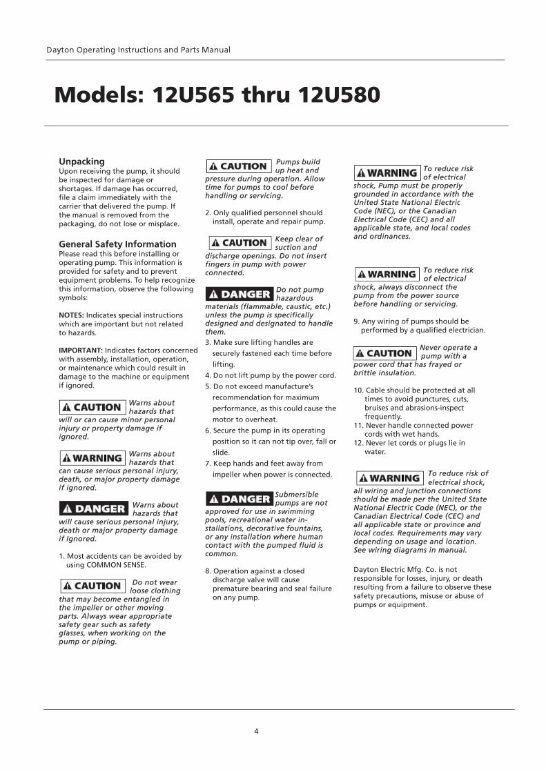
Unpacking Upon receiving the pump, it should be inspected for damage or shortages. If damage has occurred, file a claim immediately with the carrier that delivered the pump. If the manual is removed from the packaging, do not lose or misplace. General Safety Information Please read this before installing or operating pump. This information is provided for safety and to prevent equipment problems. To help recognize this information, observe the following symbols: NOTES: Indicates special instructions which are important but not related to hazards. IMPORTANT: Indicates factors concerned with assembly, installation, operation, or maintenance which could result in damage to the machine or equipment if ignored. Warns about hazards that will or can cause minor personal injury or property damage if ignored. Warns about hazards that can cause serious personal injury, death, or major property damage if ignored. Warns about hazards that will cause serious personal injury, death or major property damage if Ignored. 1. Most accidents can be avoided by
using COMMON SENSE. Do not wear
loose clothing that may become entangled in the impeller or other moving parts. Always wear appropriate safety gear such as safety glasses, when working on the pump or piping.
Pumps build up heat and pressure during operation. Allow time for pumps to cool before handling or servicing. 2. Only qualified personnel should
install, operate and repair pump. Keep clear of suction and discharge openings. Do not insert fingers in pump with power connected.
Do not pump hazardous
materials (flammable, caustic, etc.) unless the pump is specifically designed and designated to handle them. 3. Make sure lifting handles are
securely fastened each time before
lifting.
4. Do not lift pump by the power cord.
5. Do not exceed manufacture’s
recommendation for maximum
performance, as this could cause the
motor to overheat.
6. Secure the pump in its operating
position so it can not tip over, fall or
slide.
7. Keep hands and feet away from
impeller when power is connected.
Submersible pumps are not approved for use in swimming pools, recreational water in- stallations, decorative fountains, or any installation where human contact with the pumped fluid is common. 8. Operation against a closed discharge valve will cause premature bearing and seal failure on any pump.
4
Models: 12U565 thru 12U580
To reduce risk of electrical
shock, Pump must be properly grounded in accordance with the United State National Electric Code (NEC), or the Canadian Electrical Code (CEC) and all applicable state, and local codes and ordinances.
To reduce risk of electrical
shock, always disconnect the pump from the power source before handling or servicing. 9. Any wiring of pumps should be
performed by a qualified electrician. Never operate a
pump with a power cord that has frayed or brittle insulation. 10. Cable should be protected at all
times to avoid punctures, cuts, bruises and abrasions-inspect frequently.
11. Never handle connected power cords with wet hands.
12. Never let cords or plugs lie in water.
To reduce risk of electrical shock,
all wiring and junction connections should be made per the United State National Electric Code (NEC), or the Canadian Electrical Code (CEC) and all applicable state or province and local codes. Requirements may vary depending on usage and location. See wiring diagrams in manual. Dayton Electric Mfg. Co. is not responsible for losses, injury, or death resulting from a failure to observe these safety precautions, misuse or abuse of pumps or equipment.
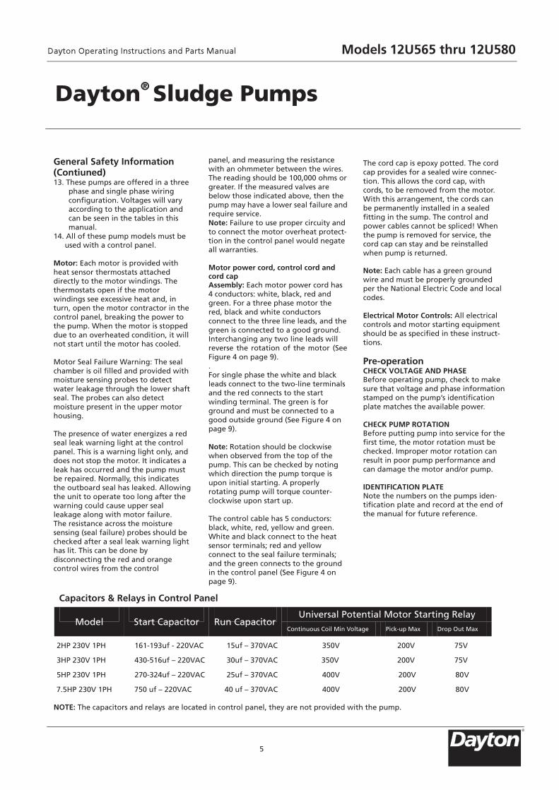
General Safety Information (Contiuned) 13. These pumps are offered in a three
phase and single phase wiring configuration. Voltages will vary according to the application and can be seen in the tables in this manual.
14. All of these pump models must be used with a control panel.
Motor: Each motor is provided with heat sensor thermostats attached directly to the motor windings. The thermostats open if the motor windings see excessive heat and, in turn, open the motor contractor in the control panel, breaking the power to the pump. When the motor is stopped due to an overheated condition, it will not start until the motor has cooled. Motor Seal Failure Warning: The seal chamber is oil filled and provided with moisture sensing probes to detect water leakage through the lower shaft seal. The probes can also detect moisture present in the upper motor housing. The presence of water energizes a red seal leak warning light at the control panel. This is a warning light only, and does not stop the motor. It indicates a leak has occurred and the pump must be repaired. Normally, this indicates the outboard seal has leaked. Allowing the unit to operate too long after the warning could cause upper seal leakage along with motor failure. The resistance across the moisture sensing (seal failure) probes should be checked after a seal leak warning light has lit. This can be done by disconnecting the red and orange control wires from the control
panel, and measuring the resistance with an ohmmeter between the wires. The reading should be 100,000 ohms or greater. If the measured valves are below those indicated above, then the pump may have a lower seal failure and require service. Note: Failure to use proper circuity and to connect the motor overheat protect-tion in the control panel would negate all warranties. Motor power cord, control cord and cord cap Assembly: Each motor power cord has 4 conductors: white, black, red and green. For a three phase motor the red, black and white conductors connect to the three line leads, and the green is connected to a good ground. Interchanging any two line leads will reverse the rotation of the motor (See Figure 4 on page 9). . For single phase the white and black leads connect to the two-line terminals and the red connects to the start winding terminal. The green is for ground and must be connected to a good outside ground (See Figure 4 on page 9). Note: Rotation should be clockwise when observed from the top of the pump. This can be checked by noting which direction the pump torque is upon initial starting. A properly rotating pump will torque counter- clockwise upon start up. The control cable has 5 conductors: black, white, red, yellow and green. White and black connect to the heat sensor terminals; red and yellow connect to the seal failure terminals; and the green connects to the ground in the control panel (See Figure 4 on page 9).
The cord cap is epoxy potted. The cord cap provides for a sealed wire connec- tion. This allows the cord cap, with cords, to be removed from the motor. With this arrangement, the cords can be permanently installed in a sealed fitting in the sump. The control and power cables cannot be spliced! When the pump is removed for service, the cord cap can stay and be reinstalled when pump is returned. Note: Each cable has a green ground wire and must be properly grounded per the National Electric Code and local codes. Electrical Motor Controls: All electrical controls and motor starting equipment should be as specified in these instruct- tions. Pre-operation CHECK VOLTAGE AND PHASE Before operating pump, check to make sure that voltage and phase informationstamped on the pump’s identification plate matches the available power. CHECK PUMP ROTATION Before putting pump into service for thefirst time, the motor rotation must be checked. Improper motor rotation can result in poor pump performance and can damage the motor and/or pump. IDENTIFICATION PLATE Note the numbers on the pumps iden- tification plate and record at the end of the manual for future reference.
5
Dayton® Sludge Pumps
Capacitors & Relays in Control Panel
2HP 230V 1PH 161-193uf - 220VAC 15uf – 370VAC 350V 200V 75V
3HP 230V 1PH 430-516uf – 220VAC 30uf – 370VAC 350V 200V 75V
5HP 230V 1PH 270-324uf – 220VAC 25uf – 370VAC 400V 200V 80V
7.5HP 230V 1PH 750 uf – 220VAC 40 uf – 370VAC 400V 200V 80V
NOTE: The capacitors and relays are located in control panel, they are not provided with the pump.
Universal Potential Motor Starting Relay
Model Start Capacitor Run CapacitorContinuous Coil Min Voltage Pick-up Max Drop Out Max
Models 12U565 thru 12U580
R
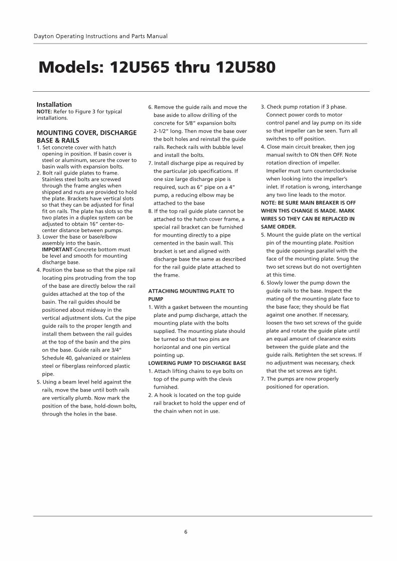
Installation NOTE: Refer to Figure 3 for typical installations. MOUNTING COVER, DISCHARGE BASE & RAILS 1. Set concrete cover with hatch opening in position. If basin cover is steel or aluminum, secure the cover to
basin walls with expansion bolts. 2. Bolt rail guide plates to frame. Stainless steel bolts are screwed through the frame angles when shipped and nuts are provided to hold the plate. Brackets have vertical slots so that they can be adjusted for final fit on rails. The plate has slots so the two plates in a duplex system can be adjusted to obtain 16” center-to- center distance between pumps.
3. Lower the base or base/elbow assembly into the basin. IMPORTANT-Concrete bottom must be level and smooth for mounting discharge base.
4. Position the base so that the pipe rail
locating pins protruding from the top
of the base are directly below the rail
guides attached at the top of the
basin. The rail guides should be
positioned about midway in the
vertical adjustment slots. Cut the pipe
guide rails to the proper length and
install them between the rail guides
at the top of the basin and the pins
on the base. Guide rails are 3/4”
Schedule 40, galvanized or stainless
steel or fiberglass reinforced plastic
pipe.
5. Using a beam level held against the
rails, move the base until both rails
are vertically plumb. Now mark the
position of the base, hold-down bolts,
through the holes in the base.
6. Remove the guide rails and move the
base aside to allow drilling of the
concrete for 5/8” expansion bolts
2-1/2” long. Then move the base over
the bolt holes and reinstall the guide
rails. Recheck rails with bubble level
and install the bolts.
7. Install discharge pipe as required by
the particular job specifications. If
one size large discharge pipe is
required, such as 6” pipe on a 4”
pump, a reducing elbow may be
attached to the base
8. If the top rail guide plate cannot be
attached to the hatch cover frame, a
special rail bracket can be furnished
for mounting directly to a pipe
cemented in the basin wall. This
bracket is set and aligned with
discharge base the same as described
for the rail guide plate attached to
the frame.
ATTACHING MOUNTING PLATE TO
PUMP
1. With a gasket between the mounting
plate and pump discharge, attach the
mounting plate with the bolts
supplied. The mounting plate should
be turned so that two pins are
horizontal and one pin vertical
pointing up.
LOWERING PUMP TO DISCHARGE BASE
1. Attach lifting chains to eye bolts on
top of the pump with the clevis
furnished.
2. A hook is located on the top guide
rail bracket to hold the upper end of
the chain when not in use.
3. Check pump rotation if 3 phase.
Connect power cords to motor
control panel and lay pump on its side
so that impeller can be seen. Turn all
switches to off position.
4. Close main circuit breaker, then jog
manual switch to ON then OFF. Note
rotation direction of impeller.
Impeller must turn counterclockwise
when looking into the impeller’s
inlet. If rotation is wrong, interchange
any two line leads to the motor.
NOTE: BE SURE MAIN BREAKER IS OFF
WHEN THIS CHANGE IS MADE. MARK
WIRES SO THEY CAN BE REPLACED IN
SAME ORDER.
5. Mount the guide plate on the vertical
pin of the mounting plate. Position
the guide openings parallel with the
face of the mounting plate. Snug the
two set screws but do not overtighten
at this time.
6. Slowly lower the pump down the
guide rails to the base. Inspect the
mating of the mounting plate face to
the base face; they should be flat
against one another. If necessary,
loosen the two set screws of the guide
plate and rotate the guide plate until
an equal amount of clearance exists
between the guide plate and the
guide rails. Retighten the set screws. If
no adjustment was necessary, check
that the set screws are tight.
7. The pumps are now properly
positioned for operation.
6
Models: 12U565 thru 12U580
7
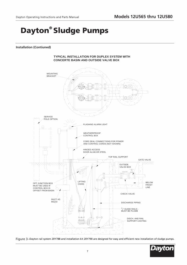
Installation (Contiuned)
Figure 3--
Dayton® Sludge Pumps
TYPICAL INSTALLATION FOR DUPLEX SYSTEM WITHCONCERTE BASIN AND OUTSIDE VALVE BOX
MOUNTINGBRACKET
SERVICEPOLE OPTION
FLASHING ALARM LIGHT
WEATHERPROOFCONTROL BOX
CORD SEAL CONNECTIONS FOR POWERAND CONTROL CORDS (NOT SHOWN)
OUTSIDEVALVE BOX
GATE VALVE
HINGED ACCESSDOOR ALUM.OR STEEL
OPT.JUNCTION BOXMUST BE USED IFCONTROL BOX ISOFFSET FROM BASIN
INLET ASREQ'D
TOP RAIL SUPPORT
BELOWFROSTLINE
CHECK VALVE
DISCHARGE PIPING
34" GUIDE RAILS -
MUST BE PLUMB
DISCH. AND RAILSUPPORT CASTING
LIFTINGCHAIN
Dayton rail system 20Y788 and installation kit 20Y790 are designed for easy and efficient new installation of sludge pumps.
Models 12U565 thru 12U580
R
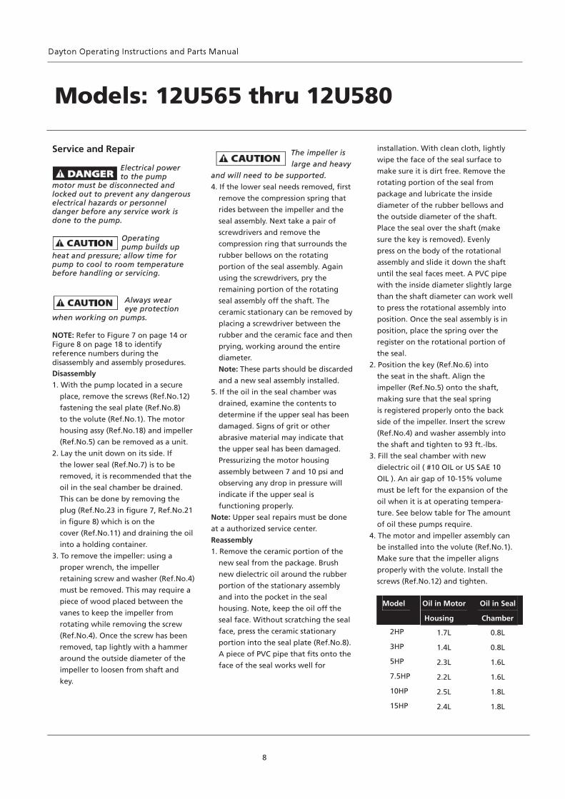
Service and Repair
Electrical power to the pump
motor must be disconnected and locked out to prevent any dangerous electrical hazards or personnel danger before any service work is done to the pump.
Operating pump builds up
heat and pressure; allow time for pump to cool to room temperature before handling or servicing.
Always wear eye protection
when working on pumps.
NOTE: Refer to Figure 7 on page 14 or Figure 8 on page 18 to identify reference numbers during the disassembly and assembly prosedures. Disassembly
1. With the pump located in a secure
place, remove the screws (Ref.No.12)
fastening the seal plate (Ref.No.8)
to the volute (Ref.No.1). The motor
housing assy (Ref.No.18) and impeller
(Ref.No.5) can be removed as a unit.
2. Lay the unit down on its side. If
the lower seal (Ref.No.7) is to be
removed, it is recommended that the
oil in the seal chamber be drained.
This can be done by removing the
plug (Ref.No.23 in figure 7, Ref.No.21
in figure 8) which is on the
cover (Ref.No.11) and draining the oil
into a holding container.
3. To remove the impeller: using a
proper wrench, the impeller
retaining screw and washer (Ref.No.4)
must be removed. This may require a
piece of wood placed between the
vanes to keep the impeller from
rotating while removing the screw
(Ref.No.4). Once the screw has been
removed, tap lightly with a hammer
around the outside diameter of the
impeller to loosen from shaft and
key.
The impeller is
large and heavy
and will need to be supported.
4. If the lower seal needs removed, first
remove the compression spring that
rides between the impeller and the
seal assembly. Next take a pair of
screwdrivers and remove the
compression ring that surrounds the
rubber bellows on the rotating
portion of the seal assembly. Again
using the screwdrivers, pry the
remaining portion of the rotating
seal assembly off the shaft. The
ceramic stationary can be removed by
placing a screwdriver between the
rubber and the ceramic face and then
prying, working around the entire
diameter.
Note: These parts should be discarded
and a new seal assembly installed.
5. If the oil in the seal chamber was
drained, examine the contents to
determine if the upper seal has been
damaged. Signs of grit or other
abrasive material may indicate that
the upper seal has been damaged.
Pressurizing the motor housing
assembly between 7 and 10 psi and
observing any drop in pressure will
indicate if the upper seal is
functioning properly.
Note: Upper seal repairs must be done
at a authorized service center.
Reassembly
1. Remove the ceramic portion of the
new seal from the package. Brush
new dielectric oil around the rubber
portion of the stationary assembly
and into the pocket in the seal
housing. Note, keep the oil off the
seal face. Without scratching the seal
face, press the ceramic stationary
portion into the seal plate (Ref.No.8).
A piece of PVC pipe that fits onto the
face of the seal works well for
installation. With clean cloth, lightly
wipe the face of the seal surface to
make sure it is dirt free. Remove the
rotating portion of the seal from
package and lubricate the inside
diameter of the rubber bellows and
the outside diameter of the shaft.
Place the seal over the shaft (make
sure the key is removed). Evenly
press on the body of the rotational
assembly and slide it down the shaft
until the seal faces meet. A PVC pipe
with the inside diameter slightly large
than the shaft diameter can work well
to press the rotational assembly into
position. Once the seal assembly is in
position, place the spring over the
register on the rotational portion of
the seal.
2. Position the key (Ref.No.6) into
the seat in the shaft. Align the
impeller (Ref.No.5) onto the shaft,
making sure that the seal spring
is registered properly onto the back
side of the impeller. Insert the screw
(Ref.No.4) and washer assembly into
the shaft and tighten to 93 ft.-lbs.
3. Fill the seal chamber with new
dielectric oil ( #10 OIL or US SAE 10
OIL ). An air gap of 10-15% volume
must be left for the expansion of the
oil when it is at operating tempera-
ture. See below table for The amount
of oil these pumps require.
4. The motor and impeller assembly can
be installed into the volute (Ref.No.1).
Make sure that the impeller aligns
properly with the volute. Install the
screws (Ref.No.12) and tighten.
8
Models: 12U565 thru 12U580
Model Oil in Motor
Housing
Oil in Seal
Chamber 2HP 1.7L 0.8L
3HP 1.4L 0.8L
5HP 2.3L 1.6L
7.5HP 2.2L 1.6L
10HP 2.5L 1.8L
15HP 2.4L 1.8L
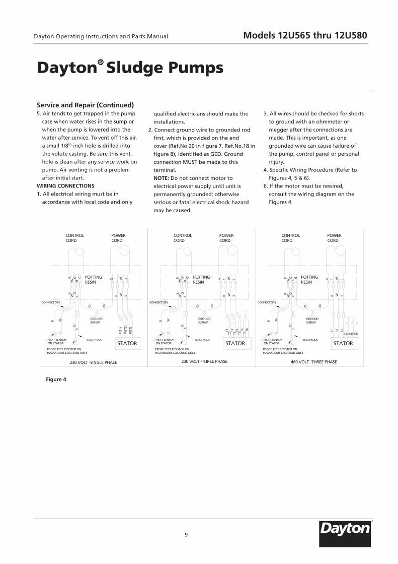
Service and Repair (Continued) 5. Air tends to get trapped in the pump
case when water rises in the sump or
when the pump is lowered into the
water after service. To vent off this air,
a small 1/8th inch hole is drilled into
the volute casting. Be sure this vent
hole is clean after any service work on
pump. Air venting is not a problem
after initial start.
WIRING CONNECTIONS
1. All electrical wiring must be in
accordance with local code and only
qualified electricians should make the
installations.
2. Connect ground wire to grounded rod
first, which is provided on the end
cover (Ref.No.20 in figure 7, Ref.No.18 in
figure 8), identified as GED. Ground
connection MUST be made to this
terminal.
NOTE: Do not connect motor to
electrical power supply until unit is
permanently grounded; otherwise
serious or fatal electrical shock hazard
may be caused.
3. All wires should be checked for shorts
to ground with an ohmmeter or
megger after the connections are
made. This is important, as one
grounded wire can cause failure of
the pump, control panel or personal
injury.
4. Specific Wiring Procedure (Refer to
Figures 4, 5 & 6).
6. If the motor must be rewired,
consult the wiring diagram on the
Figures 4.
9
STATOR
POWERCORD
CONTROLCORD
POTTINGRESIN
BW
OR
B W
OR
GROUNDSCREW
R W B
R(T
1)
W(T
2)
B(T
3)
GG
HEAT SENSORON STATOR
ELECTRODE
PROBE TEST RESISTOR ONHAZARDOUS LOCATION ONLY
230 VOLT -SINGLE PHASE
CONNECTORS
STATOR
POWERCORD
CONTROLCORD
POTTINGRESIN
BW
OR
B W
OR
GROUNDSCREW
R W B
GG
HEAT SENSORON STATOR
ELECTRODE
PROBE TEST RESISTOR ONHAZARDOUS LOCATION ONLY
230 VOLT -THREE PHASE
CONNECTORS
T1T7
T2T8
T3T9
T4T5
T6
STATOR
POWERCORD
CONTROLCORD
POTTINGRESIN
BW
OR
B W
OR
GROUNDSCREW
R W B
GG
HEAT SENSORON STATOR
ELECTRODE
PROBE TEST RESISTOR ONHAZARDOUS LOCATION ONLY
460 VOLT -THREE PHASE
CONNECTORS
T1
T4
T2 T3
T7 T5 T8 T6 T9
BW
OR R W BGG BW
OR
G BW
OR
GR W BG R W BG
Figure 4
Dayton® Sludge Pumps
Models 12U565 thru 12U580
R

10
WIRING DIAGRAM: 230V 1PH
Service and Repair (Continued)
Figure 5
Models: 12U565 thru 12U580
L1
L2
CB1
1 5
2
BLK
WH
RED
G
G
N
1 2 3 4
H1 H1
G
M1
R S1 S1
5 6 RED
SR
4 2
4 3 1 5
POWER CIRCUIT230V-1PH
BLK
BLK
BLK
YEL
YEL
M1
BLK
YEL
PUMP 1
MA
IN
STAR
TBLU START CAP.1
RUN CAP.1 STARTRELAY 1
YEL
YEL
BLU
RED RED
BLU
F1-1A
F2-1A
BLU
BLU
TAN
TAN RED
HAND HEATSENSORS
OFF
AUTO
BLU
/ WH
RD
/ WH
WHT
WHT
PUMP RUNNING
BLU / WH
PUMP 1 SEAL FAILWH / YEL
SEAL LEAK PROBES
WHT
WH
T
BLU / WH
BLU / WH
ORG
TEST
NORMAL
SILENCE
ORG
ORG
BLK
SR
ALARM LIGHT
AUDIBLE ALARM
PRP / WH
PRP
PRP
W1 W1
PUMP MOTOR MUST HAVE INTERNAL OVERLOAD PROTECTION
WH
T
NOTE: The capacitors are located in the control panel, they are not provided with the pump. See page 5 for capacitor ratings.
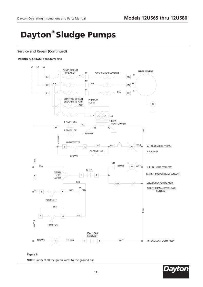
WIRING DIAGRAM: 230&460V 3PH
11
NOTE: Connect all the green wires to the ground bar.
Figure 6
Service and Repair (Continued)
Dayton® Sludge Pumps
B
W
RM1
M2
M3
M1
M1
M1 OVERLOAD ELEMENTSPUMP MOTOR
L1
L2
L3
L2L1 L3
H1 H3 H2 H4
9 10
F
AL
1 2
Y
65
7 8
R 3 4
PUMP CIRCUITBREAKER
CONTROL CIRCUITBREAKER-15 AMP
PRIMARYFUSES
1 AMP FUSE
1 AMP FUSEXF
100VATRANSFORMER
X1 X2
HIGH WATER
ALARM TEST
AL-ALARM LIGHT(RED)
F-FLASHER
Y-RUN LIGHT (YELLOW)
M.H.S. - MOTOR HEAT SENSOR
M1-MOTOR CONTACTOR
TOC-THERMAL OVERLOADCONTACT
R-SEAL LEAK LIGHT (RED)
M1
HANDOFF
AUTO
M.H.S.
M1
M1
PUMP OFF
PUMP ON
SEAL LEAKCONTACT
BLU
BLU/WH
BLU
BLU
BLU
BLU
/ WH
BLU/WH YEL/WH WHT
WH
TW
HT
WHTBLKORGB
LU/W
H
BLU
BLU/WH
WHTRD/WH
RED
REDBRN
BRN
RED
BLK
BLK
BLK
BLK
BLK
G
Models 12U565 thru 12U580
R
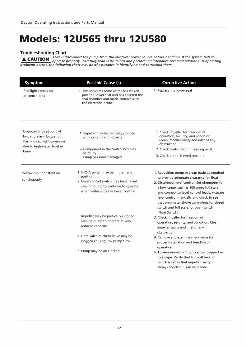
Yellow run light stays on
continuously
1. H-O-A switch may be in the hand position
2. Level control switch may have failed
causing pump to continue to operate
when water is below lower control.
3. Impeller may be partically clogged
causing pump to operate at very
reduced capacity.
4. Gate valve or check valve may be
clogged causing low pump flow.
5. Pump may be air clocked.
Red light comes on
at control box 1. This indicates some water has leaked
past the lower seal and has entered theseal chamber and made contact with the electrode probe.
1. Replace the lower seal
1. Reposition pump or clean basin as required
to provide adequate clearance for float
2. Disconnect level control. Set ohmmeter for
a low range, such as 100 ohms full scale
and connect to level control leads. Actuate
level control manually and check to see
that ohmmeter shows zero ohms for closed
switch and full scale for open switch
(Float Switch)
3. Check impeller for freedom of
operation, security, and condition. Clean
impeller cavity and inlet of any
obstruction
4. Remove and examine check valve for
proper Installation and freedom of
operation
5. Loosen union slightly to allow trapped air
to escape. Verify that turn-off level of
switch is set so that impeller cavity is
always flooded. Clean vent hole.
Symptom Possible Cause (s) Corrective Action
12
Models: 12U565 thru 12U580Troubleshooting Chart
Always disconnect the pump from the electrical power source before handling. If the system fails to operate properly , carefully read instructions and perform maintenance recommendations . If operating
problems persist, the following chart may be of assistance in identifying and correcting them .
Overload trips at control
box and alarm buzzer or
flashing red light comes on
due to high water level in
basin
1. Impeller may be partically clogged with some foreign objects
2. Component in the control box may be faulty.
3. Pump has some damaged.
1. Check impeller for freedom of operation, security, and condition. Clean impeller cavity and inlet of any
obstruction
2. Check control box, if need repair it.
3. Check pump, if need repair it.
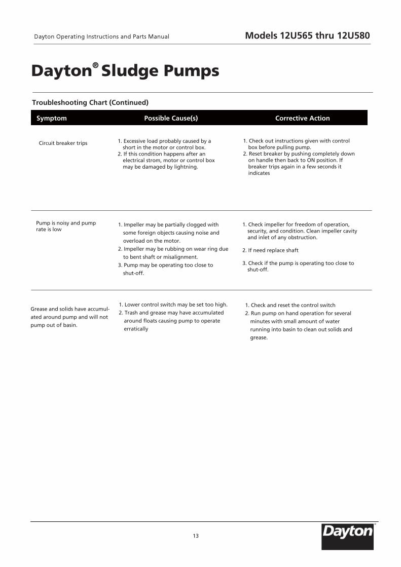
Troubleshooting Chart (Continued)
13
Symptom Possible Cause(s) Corrective Action
Dayton® Sludge Pumps
Circuit breaker trips
1. Excessive load probably caused by a
short in the motor or control box. 2. If this condition happens after an electrical strom, motor or control box may be damaged by lightning.
1. Check out instructions given with control box before pulling pump.
2. Reset breaker by pushing completely down on handle then back to ON position. If breaker trips again in a few seconds it indicates
Pump is noisy and pump rate is low
1. Impeller may be partially clogged with
some foreign objects causing noise and
overload on the motor.
2. Impeller may be rubbing on wear ring due
to bent shaft or misalignment.
3. Pump may be operating too close to
shut-off.
1. Check impeller for freedom of operation, security, and condition. Clean impeller cavity and inlet of any obstruction.
2. If need replace shaft 3. Check if the pump is operating too close to shut-off.
Grease and solids have accumul-
ated around pump and will not
pump out of basin.
1. Lower control switch may be set too high.
2. Trash and grease may have accumulated
around floats causing pump to operate
erratically
1. Check and reset the control switch
2. Run pump on hand operation for several
minutes with small amount of water
running into basin to clean out solids and
grease.
Models 12U565 thru 12U580
R

For Repair Parts, call 1-800-323-0620
24 hours a day – 365 days a year
Please provide following information: -Model number -Serial number (if any) -Part description and number as shown in parts list
14
Figure 7- Repair parts for illustration- Models: 12U565 thru 12U576
4
6
5
7
8
12
23
14
15
19
23
20
19
1
2
3
7
9
10
11
13
16
17
18
13
21
22
Models 12U565 thru 12U580

Repair Parts List
15
Part No.for Pump Models
Ref.No. Description 12U565 12U566 12U567 12U568 Q’TY1 VOLUTE ASSY PPT4NC201G PPT4NC201G PPT4NC201G PPT4NC201G 1
2 GASKET PPT4NC202G PPT4NC202G PPT4NC202G PPT4NC202G 1
3 SCREW PPT4NC203G PPT4NC203G PPT4NC203G PPT4NC203G 4
4 SCREW PPT4NC204G PPT4NC204G PPT4NC204G PPT4NC204G 1
5 IMPELLER PPT4NC205G PPT4NC205G PPT4NC205G PPT4NC305G 1
6 KEY PPT4NC206G PPT4NC206G PPT4NC206G PPT4NC206G 1
7 SHAFT SEAL PPT4NC207G PPT4NC207G PPT4NC207G PPT4NC207G 2
8 SEAL PLATE PPT4NC208G PPT4NC208G PPT4NC208G PPT4NC208G 1
9+ RING 01 PPT4NC209G PPT4NC209G PPT4NC209G PPT4NC209G 1
10 RETAINER RING PPT4NC210G PPT4NC210G PPT4NC210G PPT4NC210G 1
11 COVER PPT4NC211G PPT4NC211G PPT4NC211G PPT4NC211G 1
12 SCREW PPT4NC212G PPT4NC212G PPT4NC212G PPT4NC212G 4
13+ RING 02 PPT4NC213G PPT4NC213G PPT4NC213G PPT4NC213G 2
14 LOWER BEARING PPT4NC214G PPT4NC214G PPT4NC214G PPT4NC214G 1
15 ROTOR ASSY PPT4NC215G PPT4NC215G PPT4NC215G PPT4NC315G 1
16 UPPER BEARING PPT4NC216G PPT4NC216G PPT4NC216G PPT4NC216G 1
17 WAVE WASHER PPT4NC217G PPT4NC217G PPT4NC217G PPT4NC217G 1
18 MOTOR HOUSING SSY PPT4NC218G PPT4NC224G PPT4NC225G PPT4NC318G 1
19 SCREW PPT4NC219G PPT4NC219G PPT4NC219G PPT4NC219G 8
20 END COVER PPT4NC220G PPT4NC220G PPT4NC220G PPT4NC220G 1
21+ RING 03 PPT4NC221G PPT4NC221G PPT4NC221G PPT4NC221G 1
22 CORD ASSY PPT4NC222G PPT4NC222G PPT4NC222G PPT4NC322G 1
23 PLUG PPT4NC223G PPT4NC223G PPT4NC223G PPT4NC223G 2
(+) These are square ring for 12U565 to 12U570, and O-ring for 12U571 to 12U576
Models 12U565 thru 12U580
R
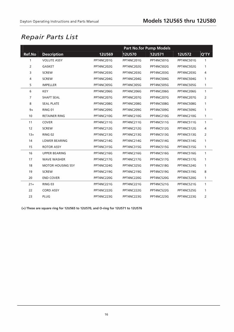
Repair Parts List
16
Part No.for Pump Models
Ref.No. Description 12U569 12U570 12U571 12U572 Q’TY1 VOLUTE ASSY PPT4NC201G PPT4NC201G PPT4NC501G PPT4NC501G 1
2 GASKET PPT4NC202G PPT4NC202G PPT4NC502G PPT4NC502G 1
3 SCREW PPT4NC203G PPT4NC203G PPT4NC203G PPT4NC203G 4
4 SCREW PPT4NC204G PPT4NC204G PPT4NC504G PPT4NC504G 1
5 IMPELLER PPT4NC305G PPT4NC305G PPT4NC505G PPT4NC505G 1
6 KEY PPT4NC206G PPT4NC206G PPT4NC206G PPT4NC206G 1
7 SHAFT SEAL PPT4NC207G PPT4NC207G PPT4NC207G PPT4NC207G 2
8 SEAL PLATE PPT4NC208G PPT4NC208G PPT4NC508G PPT4NC508G 1
9+ RING 01 PPT4NC209G PPT4NC209G PPT4NC509G PPT4NC509G 1
10 RETAINER RING PPT4NC210G PPT4NC210G PPT4NC210G PPT4NC210G 1
11 COVER PPT4NC211G PPT4NC211G PPT4NC511G PPT4NC511G 1
12 SCREW PPT4NC212G PPT4NC212G PPT4NC512G PPT4NC512G 4
13+ RING 02 PPT4NC213G PPT4NC213G PPT4NC513G PPT4NC513G 2
14 LOWER BEARING PPT4NC214G PPT4NC214G PPT4NC514G PPT4NC514G 1
15 ROTOR ASSY PPT4NC315G PPT4NC315G PPT4NC515G PPT4NC515G 1
16 UPPER BEARING PPT4NC216G PPT4NC216G PPT4NC516G PPT4NC516G 1
17 WAVE WASHER PPT4NC217G PPT4NC217G PPT4NC517G PPT4NC517G 1
18 MOTOR HOUSING SSY PPT4NC324G PPT4NC325G PPT4NC518G PPT4NC524G 1
19 SCREW PPT4NC219G PPT4NC219G PPT4NC519G PPT4NC519G 8
20 END COVER PPT4NC220G PPT4NC220G PPT4NC520G PPT4NC520G 1
21+ RING 03 PPT4NC221G PPT4NC221G PPT4NC521G PPT4NC521G 1
22 CORD ASSY PPT4NC222G PPT4NC222G PPT4NC522G PPT4NC525G 1
23 PLUG PPT4NC223G PPT4NC223G PPT4NC223G PPT4NC223G 2
(+) These are square ring for 12U565 to 12U570, and O-ring for 12U571 to 12U576
Models 12U565 thru 12U580
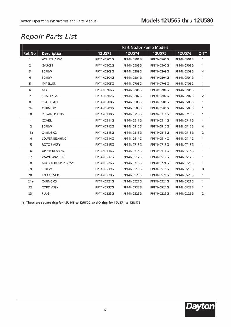
Repair Parts List
17
Part No.for Pump Models
Ref.No. Description 12U573 12U574 12U575 12U576 Q’TY1 VOLUTE ASSY PPT4NC501G PPT4NC501G PPT4NC501G PPT4NC501G 1
2 GASKET PPT4NC502G PPT4NC502G PPT4NC502G PPT4NC502G 1
3 SCREW PPT4NC203G PPT4NC203G PPT4NC203G PPT4NC203G 4
4 SCREW PPT4NC504G PPT4NC504G PPT4NC504G PPT4NC504G 1
5 IMPELLER PPT4NC505G PPT4NC705G PPT4NC705G PPT4NC705G 1
6 KEY PPT4NC206G PPT4NC206G PPT4NC206G PPT4NC206G 1
7 SHAFT SEAL PPT4NC207G PPT4NC207G PPT4NC207G PPT4NC207G 2
8 SEAL PLATE PPT4NC508G PPT4NC508G PPT4NC508G PPT4NC508G 1
9+ O-RING 01 PPT4NC509G PPT4NC509G PPT4NC509G PPT4NC509G 1
10 RETAINER RING PPT4NC210G PPT4NC210G PPT4NC210G PPT4NC210G 1
11 COVER PPT4NC511G PPT4NC511G PPT4NC511G PPT4NC511G 1
12 SCREW PPT4NC512G PPT4NC512G PPT4NC512G PPT4NC512G 4
13+ O-RING 02 PPT4NC513G PPT4NC513G PPT4NC513G PPT4NC513G 2
14 LOWER BEARING PPT4NC514G PPT4NC514G PPT4NC514G PPT4NC514G 1
15 ROTOR ASSY PPT4NC515G PPT4NC715G PPT4NC715G PPT4NC715G 1
16 UPPER BEARING PPT4NC516G PPT4NC516G PPT4NC516G PPT4NC516G 1
17 WAVE WASHER PPT4NC517G PPT4NC517G PPT4NC517G PPT4NC517G 1
18 MOTOR HOUSING SSY PPT4NC526G PPT4NC718G PPT4NC724G PPT4NC726G 1
19 SCREW PPT4NC519G PPT4NC519G PPT4NC519G PPT4NC519G 8
20 END COVER PPT4NC520G PPT4NC520G PPT4NC520G PPT4NC520G 1
21+ O-RING 03 PPT4NC521G PPT4NC521G PPT4NC521G PPT4NC521G 1
22 CORD ASSY PPT4NC527G PPT4NC722G PPT4NC522G PPT4NC525G 1
23 PLUG PPT4NC223G PPT4NC223G PPT4NC223G PPT4NC223G 2
(+) These are square ring for 12U565 to 12U570, and O-ring for 12U571 to 12U576
Models 12U565 thru 12U580
R
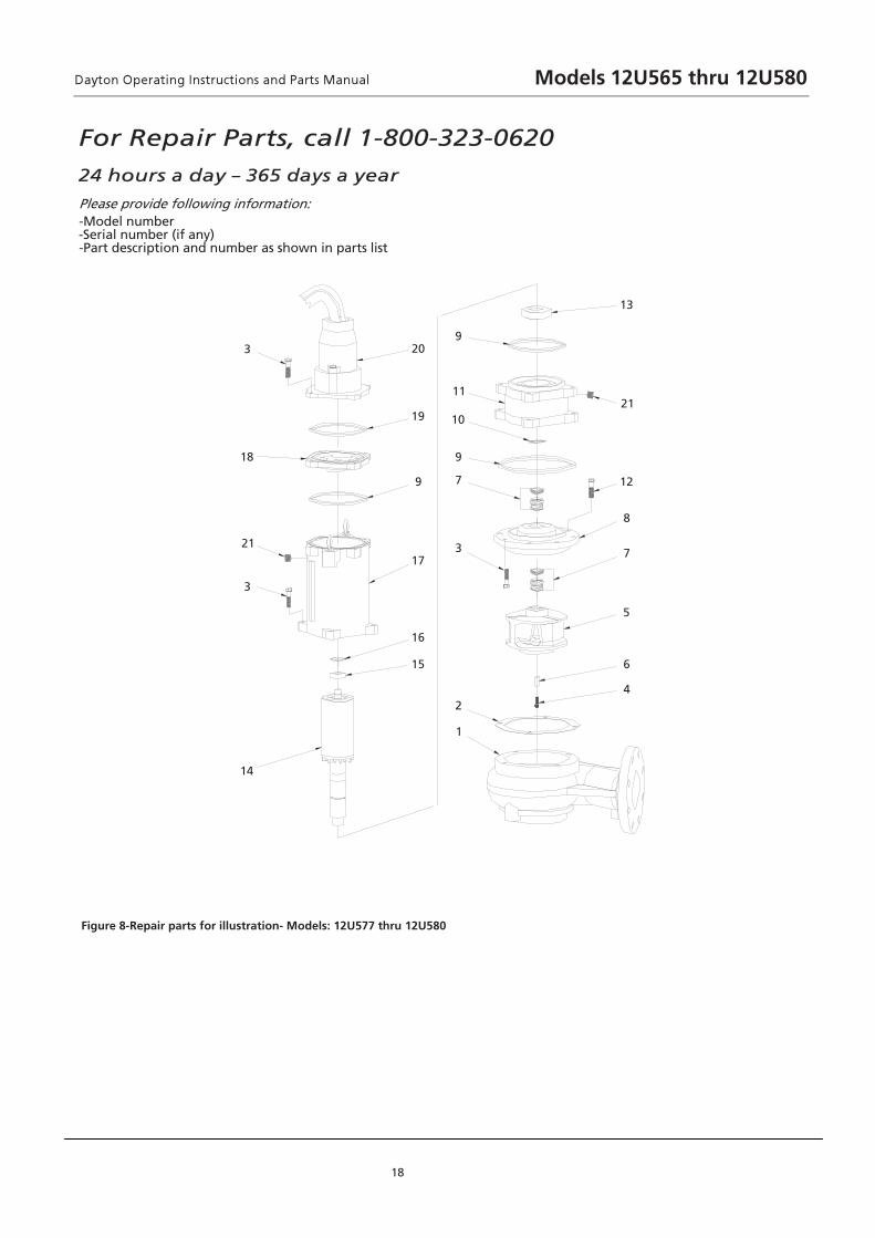
For Repair Parts, call 1-800-323-0620
24 hours a day – 365 days a year
Please provide following information: -Model number -Serial number (if any) -Part description and number as shown in parts list
18
Figure 8-Repair parts for illustration- Models: 12U577 thru 12U580
4
6
5
7
8
12
21
13
14
3
21
18
3
1
2
3
7
9
10
11
9
15
16
17
9
19
20
Models 12U565 thru 12U580

Repair Parts List
19
Part No.for Pump Models
Ref.No. Description 12U577 12U578 12U579 12U580 Q’TY
1 VOLUTE A 1 G101CN4TPP G101CN4TPP G101CN4TPP G101CN4TPP YSS
2 GA 1 G201CN4TPP G201CN4TPP G201CN4TPP G201CN4TPP TEKS
8 G915CN4TPP G915CN4TPP G915CN4TPP G915CN4TPP WERCS 3
1 G405CN4TPP G405CN4TPP G405CN4TPP G405CN4TPP WERCS 4
1 G551CN4TPP G551CN4TPP G501CN4TPP G501CN4TPP RELLEPMI 5
1 G601CN4TPP G601CN4TPP G601CN4TPP G601CN4TPP YEK 6
7 SHAFT SEA 2 G701CN4TPP G701CN4TPP G701CN4TPP G701CN4TPP L
8 SEAL PLA 1 G801CN4TPP G801CN4TPP G801CN4TPP G801CN4TPP ET
3 G901CN4TPP G901CN4TPP G901CN4TPP G901CN4TPP 10 GNIR-O 9
10 RETAINER RING PPT4NC110G PPT4NC110G PPT4NC110G PPT4NC110G 1
1 G111CN4TPP G111CN4TPP G111CN4TPP G111CN4TPP REVOC 11
8 G211CN4TPP G211CN4TPP G211CN4TPP G211CN4TPP WERCS 21
13 LOWER BEARING PPT4NC113G PPT4NC113G PPT4NC113G PPT4NC113G 1
14 ROTOR A 1 G451CN4TPP G451CN4TPP G411CN4TPP G411CN4TPP YSS
15 UPPER BEARING PPT4NC115G PPT4NC115G PPT4NC115G PPT4NC115G 1
16 WAVE WASHER PPT4NC116G PPT4NC116G PPT4NC116G PPT4NC116G 1
17 MOTOR HOUSING ASSY PPT4NC117G PPT4NC124G PPT4NC156G PPT4NC158G 1
1 G811CN4TPP G811CN4TPP G811CN4TPP G811CN4TPP REVOC DNE 81
1 G911CN4TPP G911CN4TPP G911CN4TPP G911CN4TPP 20 GNIR -O 91
20 CORD A 1 G021CN4TPP G751CN4TPP G521CN4TPP G021CN4TPP YSS
2 G322CN4TPP G322CN4TPP G322CN4TPP G322CN4TPP GULP 12
Models 12U565 thru 12U580
R

For Repair Parts, call 1-800-323-0620
24 hours a day – 365 days a year
Please provide following information: -Model number -Serial number (if any) -Part description and number as shown in parts list
20
Figure 9 – Power Cord Assembly
Power cord
Gland Nut
Adaptor
Sleeve
Power Cord Set
O-ring
Terminal
EPOXY
Lead Wire/Power Cord Lead wire/Control Cord
Terminal
Control Cord
AB
Models 12U565 thru 12U580

LIMITED WARRANTY
DAYTON ONE-YEAR LIMITED WARRANTY. DAYTON SLUDGE PUMPS, MODELS COVERED IN THIS MANUAL, ARE WARRANTED BY
DAYTON ELECTRIC MFG. CO. (DAYTON) TO THE ORIGINAL USER AGAINST DEFECTS IN WORKMANSHIP OR MATERIALSUNDER
NORMAL USE FOR ONE YEAR AFTER DATE OF PURCHASE. ANY PART WHICH IS DETERMINED TO BE DEFECTIVE IN MATERIAL OR
WORKMANSHIP AND RETURNED TO AN AUTHORIZED SERVICE LOCATION, AS DAYTON DESIGNATES, SHIPPING COSTS PREPAID,
WILL BE, AS THE EXCLUSIVE REMEDY, REPAIRED OR REPLACED AT DAYTON’S OPTION. FOR LIMITED WARRANTY CLAIM
PROCEDURES, SEE “PROMPT DISPOSITION” BELOW. THIS LIMITED WARRANTY GIVES PURCHASERS SPECIFIC LEGAL RIGHTS WHICH
VARY FROM JURISDICTION TO JURISDICTION. LIMITATION OF LIABILITY. INCIDENTAL DAMAGES IS EXPRESSLY DISCLAIMED. DAYTON’S LIABILITY IN ALL EVENTS IS LIMITED TO AND SHALL NOT EXCEED THE
PURCHASE PRICE PAID. WARRANTY DISCLAIMER. A DILIGENT EFFORT HAS BEEN MADE TO PROVIDE PRODUCT INFORMATION AND ILLUSTRATE
THE PRODUCTS IN THIS LITERATURE ACCURATELY; HOWEVER, SUCH INFORMATION AND ILLUSTRATIONS ARE FOR THE SOLE
PURPOSE OF IDENTIFICATION, AND DOES NOT EXPRESS OR IMPLY A WARRANTY THAT THE PRODUCTS ARE MERCHANTABLE, OR
FIT FOR A PARTICULAR PURPOSE, OR THAT THE PRODUCTS WILL NECESSARILY CONFORM TO THE ILLUSTRATIONS OR
DESCRIPTIONS. EXCEPT AS PROVIDED BELOW, NO WARRANTY OR AFFIRMATION OF FACT, EXPRESSED OR IMPLIED, OTHER THAN
AS STATED IN THE “LIMITED WARRANTY” ABOVE IS MADE OR AUTHORIZED BY DAYTON.
Technical Advice and Recommendations, Disclaimer. Notwithstanding any past practice or dealings or trade
custom, sales shall not include the furnishing of technical advice or assistance or system design. Dayton assumes no obligations
or liability on account of any unauthorized recommendations, opinions or advice as to the choice, installation or use of
products. Product Suitability. Many jurisdictions have codes and regulations governing sales, construction, installation, and/or use of
products for certain purposes, which may vary from those in neighboring areas. While attempts are made to assure that Dayton
products comply with such codes, Dayton cannot guarantee compliance, and cannot be responsible for how the product is installed
or used. Before purchase and use of a product, review the product applications, and all applicable national and local codes and
regulations, and be sure that the product, installation, and use will comply with them.
Certain aspects of disclaimers are not applicable to consumer products; e.g., (a) some jurisdictions do not allow the exclusion or
limitation of incidental or consequential damages, so the above limitation or exclusion may not apply to you; (b) also, some
jurisdictions do not allow a limitation on how long an implied warranty lasts, consequently the above limitation may not apply to
you; and (c) by law, during the period of this Limited Warranty, any implied warranties of implied merchantability or fitness for a
particular purpose applicable to consumer products purchased by consumers, may not be excluded or otherwise disclaimed.
Prompt Disposition. A good faith effort will be made for prompt correction or other adjustment with respect to any
product which proves to be defective within limited warranty. For any product believed to be defective within limited
warranty, first write or call dealer from whom the product was purchased. Dealer will give additional directions. If unable to
resolve satisfactorily, write to Dayton at address below, giving dealer’s name, address, date, and number of dealer’s invoice,
and describing the nature of the defect. Title and risk of loss pass to buyer on delivery to common carrier. If product was
damaged in transit to you, file claim with carrier.
21
Dayton® Sludge Pumps
TO THE EXTENT ALLOWABLE UNDER APPLICABLE LAW, DAYTON’S LIABILITY FOR CONSEQUENTIAL AND
Manufactured for Dayton Electric Mfg. Co., 100 Grainger Parkway, Lake Forest, IL 60045 USA
Models 12U565 thru 12U580
R
Notes
22
Models 12U565 thru 12U580
TEMPERATURA………..140°F Intermitente; 104°F Continuo
IMPULSOR………………2 Veletas, encerrado
MANEJO SÓLIDO….......3” (76.2.mm) esférico
SELLO……………….......TIPO 11, Mecánico doble
CABLE DE ENTRADA……20ft. (6m) cable, SOW epoxi carcasa
sellada con arandela de presión
secundaria para el sellado y
protección
MATERIAL DE SELLO………Carburo de silicio,Cerámica, SS
COJINTE INFERIOR………....Hilera individuo, diseño de la bola
de lubricación de aceite, carga y
empuje radial
COJINTE SUPERIOR……..... Hilera individuo, diseño de la bola
de lubricación de aceite, carga radial
VELOCIDAD…………………1750 RPM
Deber……………………...…Continuo
Form 5S6908 Impreso en China
09439
Versión 1
TONO100
05/2013
FORM # 897
Modelo 12U565 vía 12U580
Por favor, lea este manual de instrucciones detenidamente antes a montar, instalar, operar o mantener este producto. Seguir todas informaciones de seguridad puede proteger a usted mismo y a otros. Por favor, asegúrese de cumplir las instrucciones.El no cumplir con las instrucciones de seguridad podría causar lesiones corporales graves y / o la destrucción de bienes. Guarde bien este manual de instrucciones para su futura referencia.
Dayton® Lodo Bombas
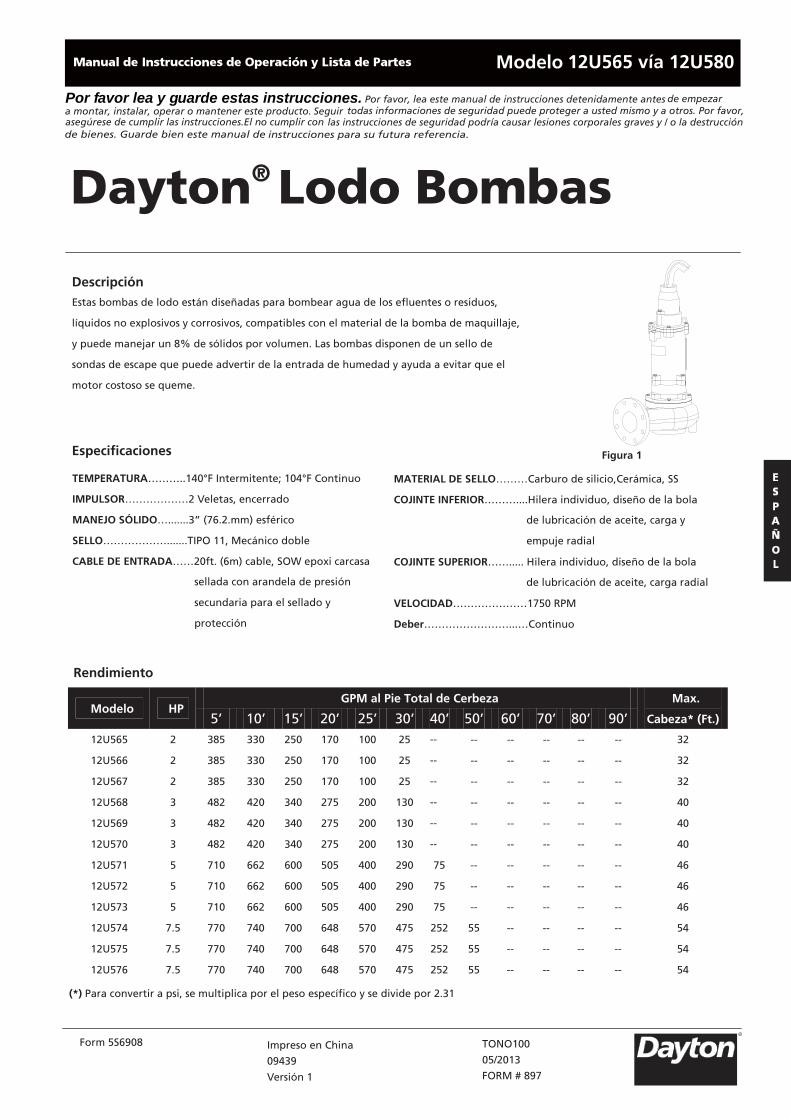
Descripción Estas bombas de lodo están diseñadas para bombear agua de los efluentes o residuos,
líquidos no explosivos y corrosivos, compatibles con el material de la bomba de maquillaje,
y puede manejar un 8% de sólidos por volumen. Las bombas disponen de un sello de
sondas de escape que puede advertir de la entrada de humedad y ayuda a evitar que el
motor costoso se queme.
Figura 1
Rendimiento
Especificaciones
GPM al Pie Total de Cerbeza Modelo HP
5’ 10’ 15’ 20’ 25’ 30’ 40’ 50’ 60’ 70’ 80’ 90’
Max.
Cabeza* (Ft.)
12U565 2 385 330 250 170 100 25 -- -- -- -- -- -- 32
12U566 2 385 330 250 170 100 25 -- -- -- -- -- -- 32
12U567 2 385 330 250 170 100 25 -- -- -- -- -- -- 32
12U568 3 482 420 340 275 200 130 -- -- -- -- -- -- 40
12U569 3 482 420 340 275 200 130 -- -- -- -- -- -- 40
12U570 3 482 420 340 275 200 130 -- -- -- -- -- -- 40
12U571 5 710 662 600 505 400 290 75 -- -- -- -- -- 46
12U572 5 710 662 600 505 400 290 75 -- -- -- -- -- 46
12U573 5 710 662 600 505 400 290 75 -- -- -- -- -- 46
12U574 7.5 770 740 700 648 570 475 252 55 -- -- -- -- 54
12U575 7.5 770 740 700 648 570 475 252 55 -- -- -- -- 54
12U576 7.5 770 740 700 648 570 475 252 55 -- -- -- -- 54
(*) Para convertir a psi, se multiplica por el peso específico y se divide por 2.31
R
Por f avor lea y g uarde estas instrucciones. de empezar
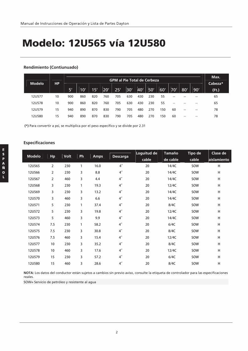
Modelo Hp Volt Ph Amps Descarga Loguitud de
cable
Tamaño
de cable
Tipo de
cable
Clase de
aislamiento
Especificaciones
2
Rendimiento (Contiunuado)
GPM al Pie Total de Cerbeza Modelo HP
5’ 10’ 15’ 20’ 25’ 30’ 40’ 50’ 60’ 70’ 80’ 90’
Max.
Cabeza*
(Ft.)
12U577 10 900 860 820 760 705 630 430 230 55 -- -- -- 65
12U578 10 900 860 820 760 705 630 430 230 55 -- -- -- 65
12U579 15 940 890 870 830 790 705 480 270 150 60 -- -- 78
12U580 15 940 890 870 830 790 705 480 270 150 60 -- -- 78
(*) Para convertir a psi, se multiplica por el peso específico y se divide por 2.31
NOTA: Los datos del conductor están sujetos a cambios sin previo aviso, consulte la etiqueta de controlador para las especificaciones reales.
SOW= Servicio de petróleo y resistente al agua
Modelo: 12U565 vía 12U580
12U565 2 230 1 16.0 4”
12U580 15 460 3 28.6 4”
12U579 15 230 3 57.2 4”
12U578 10 460 3 17.6 4”
12U577 10 230 3 35.2 4”
12U576 7.5 460 3 15.4 4”
12U575 7.5 230 3 30.8 4”
12U574 7.5 230 1 58.2 4”
12U573 5 460 3 9.9 4”
12U572 5 230 3 19.8 4”
12U566 2 230 3 8.8 4”
12U567 2 460 3 4.4 4”
12U571 5 230 1 37.4 4”
12U570 3 460 3 6.6 4”
12U569 3 230 3 13.2 4”
12U568 3 230 1 19.3 4”
20 14/4C SOW H
20 14/4C SOW H
20 14/4C SOW H
20 12/4C SOW H
20 14/4C SOW H
20 14/4C SOW H
20 8/4C SOW H
20 12/4C SOW H
20 14/4C SOW H
20 6/4C SOW H
20 8/4C SOW H
20 12/4C SOW H
20 8/4C SOW H
20 12/4C SOW H
20 6/4C SOW H
20 8/4C SOW H
Dayton® Lodo Bombas
3
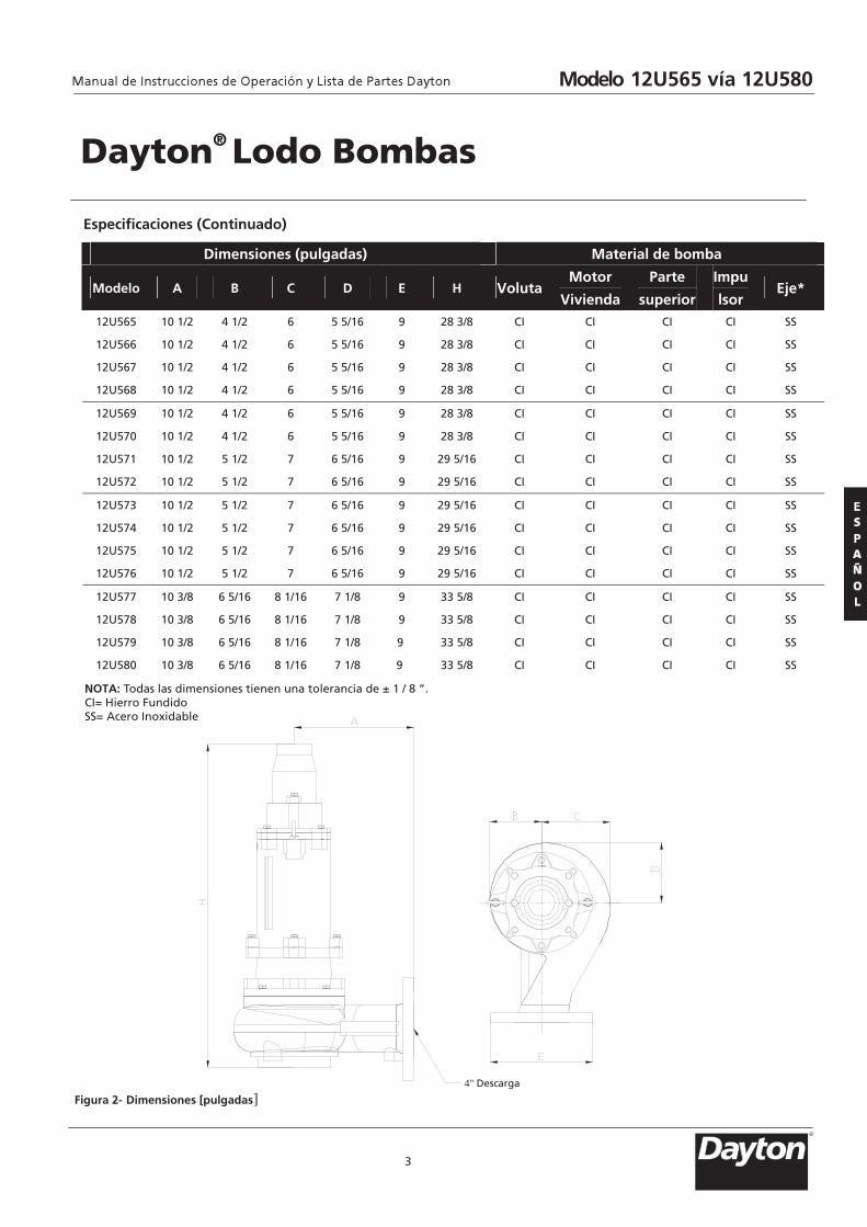
Especificaciones (Continuado)
Figura 2- Dimensiones [pulgadas]
Dimensiones (pulgadas) Material de bomba
Modelo A B C D E H VolutaMotor
Vivienda
Parte
superior
Impu
lsor Eje*
12U565 10 1/2 4 1/2 6 5 5/16 9 28 3/8 CI CI CI CI SS
12U566 10 1/2 4 1/2 6 5 5/16 9 28 3/8 CI CI CI CI SS
12U567 10 1/2 4 1/2 6 5 5/16 9 28 3/8 CI CI CI CI SS
12U568 10 1/2 4 1/2 6 5 5/16 9 28 3/8 CI CI CI CI SS
12U569 10 1/2 4 1/2 6 5 5/16 9 28 3/8 CI CI CI CI SS
12U570 10 1/2 4 1/2 6 5 5/16 9 28 3/8 CI CI CI CI SS
12U571 10 1/2 5 1/2 7 6 5/16 9 29 5/16 CI CI CI CI SS
12U572 10 1/2 5 1/2 7 6 5/16 9 29 5/16 CI CI CI CI SS
12U573 10 1/2 5 1/2 7 6 5/16 9 29 5/16 CI CI CI CI SS
12U574 10 1/2 5 1/2 7 6 5/16 9 29 5/16 CI CI CI CI SS
12U575 10 1/2 5 1/2 7 6 5/16 9 29 5/16 CI CI CI CI SS
12U576 10 1/2 5 1/2 7 6 5/16 9 29 5/16 CI CI CI CI SS
12U577 10 3/8 6 5/16 8 1/16 7 1/8 9 33 5/8 CI CI CI CI SS
12U578 10 3/8 6 5/16 8 1/16 7 1/8 9 33 5/8 CI CI CI CI SS
12U579 10 3/8 6 5/16 8 1/16 7 1/8 9 33 5/8 CI CI CI CI SS
12U580 10 3/8 6 5/16 8 1/16 7 1/8 9 33 5/8 CI CI CI CI SS
NOTA: Todas las dimensiones tienen una tolerancia de ± 1 / 8 ”. CI= Hierro Fundido SS= Acero Inoxidable
Modelo 12U565 vía 12U580
4" Descarga
R
Para reducir el riesgo del choque
eléctrico, la bomba tiene que conec- tarse a tierra adecuadamente de acuerdo con el Código Eléctrico de EEUU (NEC), o Código Eléctrico de Canadá (CEC), así como todos los códigos y decretos aplicables locales, y los de estado.
Para reducir el riesgo del
choque eléctrico, la bomba siempre está desconectada con la fuente de alimentación ante manejo o funcionamiento.
9. Todo el cableado de las bombas debe ser realizada por un electricista calificado
Nunca opere una
bomba con un cordón de potencia que se ha deshila-chado o con el aislamiento quebradizo 10. Cable debe ser protegido en todo el
tiempo para evitar el pinchazo, cortes, magulladura y abrasiones- haga la inspección frecuentemente.
11. Nunca toque los cables de alimenta- ción conectados con las manos mojadas.
12. Nunca deje que los cables o enchufes se encuentran en el agua.
Para reducir el
riesgo del choqueeléctrico, la bomba tiene que conectarse a tierra adecuadamente de acuerdo con el Código Eléctrico de EEUU (NEC), o Código Eléctrico de anadá (CEC), así como todos los códigos y decretos aplicables locales, y los de estado. Los requerimientos pueden variarse en función de uso y Ubicación. Vea el esquema de cableado en manual. Dayton Electric Mfg. Co.no está responsable por las pérdidas, lesiones, o muerte causadas por el fallo de cumplir estas precauciones de seguridad, mal uso o abusos de bombas o equipos.
4
Modelo: 12U565 vía 12U580
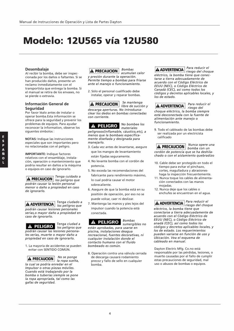
Bombas acumulan calor
y presión durante la operación. Permite tiempo a bombas para friarse ante el manejo o funcionamiento. 2. Sólo el personal cualificado debe
instalar, operar y reparar bombas.
Se mantenga libre de succión y
descarga aperturas. No introduzca- clear los dedos en bombas conectadas con corriente.
No bombee los materiales
peligrosos(inflamable, cáustico,etc), a menos que la bombaes específica- mente diseñada y designada para manejarlo. 3. Cada vez antes de levantarse, asegure
que los mangos de levantamiento
están fijadas seguramente.
4. No levante bomba con el cordón de
potencia.
5. No exceda las recomendaciones del
fabricante para rendimiento máximo,
lo cual podría causar el motor
sobrecaliente.
6. Asegure de que la bomba está en su
positión de operación, por eso no se
puede volcar, caer ni deslizar.
7. Mantenga las manos y pies lejos del
impulsor cuando la potencia está
conectada.
Bombas sumergibles no
están aprobadas, para usarse en piscina, instalaciones deagua recreacional, fuentes decorativas, ni cualquier instalación donde el contacto humano con el fluido bombeado es común. 8. Operación contra una válvula cerrada
de descarga causará rodamiento precoz y fallo de sello en cualquier bomba.
Desembalaje Al recibir la bomba, debe ser inspec- cionada por los daños o faltantes. Si se han producido daños, presente un reclamo inmediatamente con el transportista que entrega la bomba. Si el manual se retira de los envases, no se pierde o extravía. Información General de Seguridad Por favor léalo antes de instalar o operar bomba.Esta información se ofrece para la seguridad y prevenir los problemas de equipos. Para ayudar reconocer la information, observe los siguentes símbolos : NOTAS: Indique las instrucciones especiales que son importantes pero no relacionadas con el peligro. IMPORTANTE: Indique factores relativos con el ensamblaje, instala- ción, operación o mantenimiento que podría resultar en daños a la máquina o equipos en caso de ignorarlo. Tenga cuidado a
los peligros que podrán causar la lesión personal menor o daño a propiedad en caso de ignorarlo. Tenga ciudado a
los peligros que podrán causar lesiones personales serias,o mayor daño a propiedad en caso de ignorarlo. Tenga ciudad a
los peligros que podrán causar las lesiones persona- les serias, muerte o mayor daño a propiedad en caso de ignorarlo. 1. La mayoría de accidentes se pueden
evitar con SENTIDO COMÚN.
No se ponge la ropa suelta,
la cual se podría enredar en el Impulsor o otras piezas móviles. Cuando está trabajando por la bomba o tuberías siemple se pone la ropa apropriada, tal como las gafas de seguridad.

Información General de Seguridad (Contiunado) 13. Estas bombas están disponibles en
una tercera fase y una fase sola de la configuración de cableado. Tensiones variará en función de la aplicación y se puede ver en las tablas de este manual.
14. Todos estos modelos de la bomba se debe utilizar con un panel de control.
Motor: Cada motor dispone de termos- tatos de sensor de calor conectados directamente a las bobinas del motor. Los termostatos se abren si las bobinas del motor vean el calor excesivo y, a su vez, abra el contratista de motor en el panel de control, rompiendo el poder de la bomba. Cuando el motor está parado debido a una condición de sobrecalentamiento, no se iniciará hasta que el motor se haya enfriado. Advertencia de fallos en el sello del motor: La cámara del sello se llena de aceite y se proporciona de sondas de humedad de detección para detectar fugas de agua a través del eje inferior del sello. Las sondas también pueden detectar la humedad en la vivienda superior del motor. La presencia de agua se energiza una fuga de sello rojo la luz de advertencia en el panel de control. Esta es sólo una luz de advertencia, y no se detiene el motor. Se indica una fuga se ha produ- cido y la bomba debe ser reparada. Normalmente, esto indica que el sello externo se ha filtrado. Permitiendo que la unidad funcione demasiado tiempo después de la advertencia, pueden producirse fugas del sello superior, junto con falla en el motor. La resisten- cia a través de la humedad de detección (falla del sello) sondas se debe compro- bar después de una fuga del sello se ha encendido la luz de advertencia. Esto se puede hacer mediante la desconexión de los cables de control de color rojo y naranja del panel de control
y mide la resistencia con un óhmetro entre los cables. La lectura debe ser de 100.000 ohmios o mayor. Si los valores medidos están por debajo de los indicados anteriores, la bomba puede tener un fallo en el sello bajo y requie- ren de servicios.Nota: Si no se utiliza un circuito adecuado y no se conecta el motor de protección contra sobrecalentamiento en el panel de control se niegan todas las garantías. Cable de alimentación, Cable de control y Tapa del cable del Motor Assembly: Cada cable de alimentación del motor tiene 4 conductores: blanco, negro, rojo y verde.De motor de tres fases, los conductores de color rojo, blanco y negro para conectar los tres cables de la línea, y el verde está conectado a una buena tierra. Intercambiando dos terminales de línea se invertirá el giro del motor De una fase sola,los cables de color blanco y negro se conectan a los terminales de dos líneas y el rojo se conecta al terminal de la bobina de arranque. El verde es para la tierra y debe estar conectado a una tierra fuera buena. (vea Figura 4 en la página 9). Nota: Rotación debe ser hacia la derecha cuando se observa desde la parte superior de la bomba. Esto se puede comprobar observando la dirección que el par de la bomba es del arranque inicial. Una bomba adecuada rotación será par a la izquierda en el arranque. El cable de control dispone de 5 conductores: negro, blanco, rojo, amarillo y verde. Blanco y negro se conectan a los terminales del sensor de calor, rojo y amarillo se conectan a los terminales de sello fracaso, y el verde se conecta a la tierra en el panel de control. (vea Figura 4 en la página 7).
5
Dayton® Lodo Bombas
Condensadores & Relé del Panel de control Modelo Capacitor de
arranque
Condensador de
funcionamiento
NOTA: Los condensadores & relé cubiertos en panel de control, no se proporcionan con la bomba
La tapa del cable es de epoxi en maceta.La tapa del cable ofrece una conexión de cable sellado. Esto permite que la tapa del cable, con cuerdas, para ser removido del motor. Con esta disposi- ción, los cables pueden ser instalados de forma permanente en un accesorio de sellado en el sumidero. Los cables de control y el poder no se puede empal- mar! Cuando la bomba se retira del servicio, la tapa del cordón puede permanecer y ser reinstalado cuando la bomba se devuelve. Nota: Cada cable tiene un cable de tierra verde y debe estar debidamente fundamentada por el Código Eléctrico Nacional y los códigos locales. Controles Eléctricos Motor: Todos los controles eléctricos y equipos de arran- que del motor deben ser como se espe- cifican en estas instrucciones. Pre-operación COMPRUEBE VOLTAJE Y FASE Antes de operar la bomba, compruebe para asegurar que la información de voltaje y fase sellada en la placa de identificación de bomba está conforme a la potencia disponible. VERTIFIQUE LA ROTACIÓN DE BOMBA Antes de poner la bomba en servicio por primera vez, la rotación del motor debe ser revisado. El giro del motor incorre- cto puede resultar en un rendimiento pobre y la bomba puede dañar el motor y / o la bomba. PLACA DE IDENTIFICACIÓN Tenga en cuenta de los números en la placa de identificación de bombas y el registro al final del manual para referencia futura.
Relé Universal Motor de partida potencialBobina de tensión continua Min
Pick-up Max Drop Out Max
2HP 230V 1PH 161-193uf - 220VAC 15uf – 370VAC 350 V 200V 75V
3HP 230V 1PH 430-516uf – 220VAC 30uf – 370VAC 350V 200V 75V
5HP 230V 1PH 270-324uf – 220VAC 25uf – 370VAC 400V 200V 80V
7.5HP 230V 1PH 750 uf – 220VAC 40 uf – 370VAC 400V 200V 80V
Modelo 12U565 vía 12U580
R
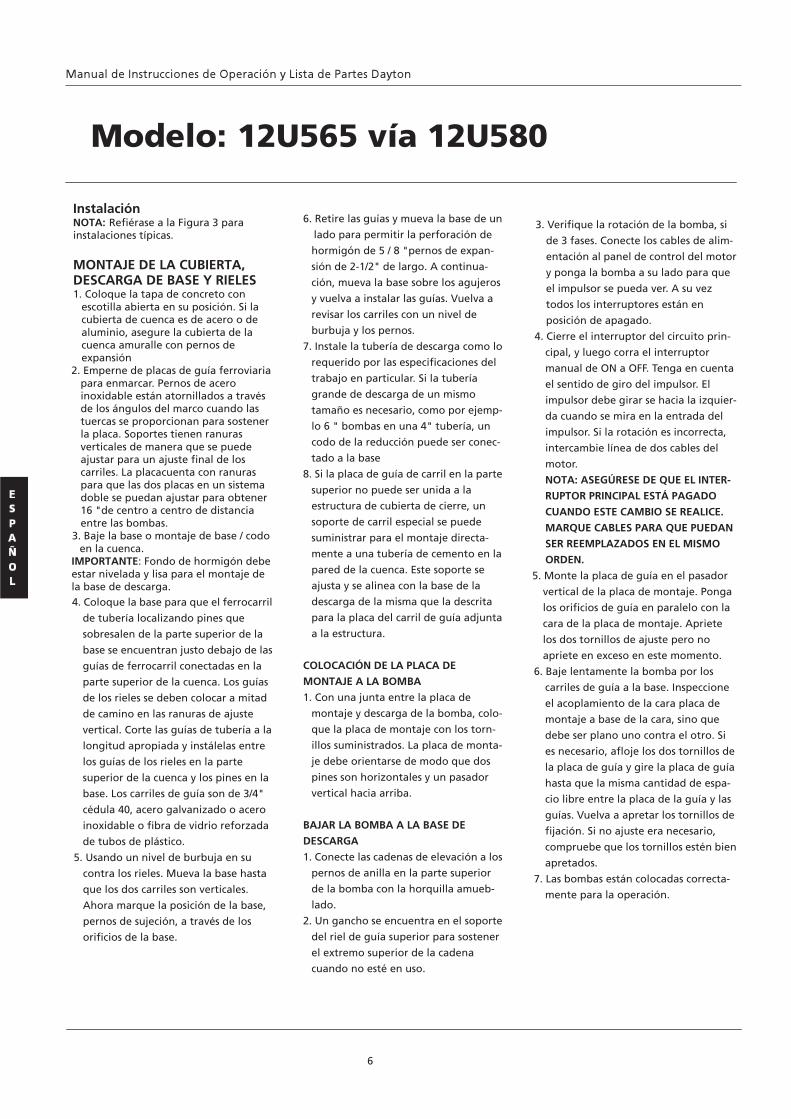
Instalación NOTA: Refiérase a la Figura 3 para instalaciones típicas. MONTAJE DE LA CUBIERTA, DESCARGA DE BASE Y RIELES 1. Coloque la tapa de concreto con
escotilla abierta en su posición. Si la cubierta de cuenca es de acero o de aluminio, asegure la cubierta de la cuenca amuralle con pernos de expansión
2. Emperne de placas de guía ferroviaria para enmarcar. Pernos de acero inoxidable están atornillados a través de los ángulos del marco cuando las tuercas se proporcionan para sostener la placa. Soportes tienen ranuras verticales de manera que se puede ajustar para un ajuste final de los carriles. La placacuenta con ranuras para que las dos placas en un sistema doble se puedan ajustar para obtener 16 "de centro a centro de distancia entre las bombas.
3. Baje la base o montaje de base / codo en la cuenca.
IMPORTANTE: Fondo de hormigón debe estar nivelada y lisa para el montaje de la base de descarga. 4. Coloque la base para que el ferrocarril
de tubería localizando pines que
sobresalen de la parte superior de la
base se encuentran justo debajo de las
guías de ferrocarril conectadas en la
parte superior de la cuenca. Los guías
de los rieles se deben colocar a mitad
de camino en las ranuras de ajuste
vertical. Corte las guías de tubería a la
longitud apropiada y instálelas entre
los guías de los rieles en la parte
superior de la cuenca y los pines en la
base. Los carriles de guía son de 3/4"
cédula 40, acero galvanizado o acero
inoxidable o fibra de vidrio reforzada
de tubos de plástico.
5. Usando un nivel de burbuja en su
contra los rieles. Mueva la base hasta
que los dos carriles son verticales.
Ahora marque la posición de la base,
pernos de sujeción, a través de los
orificios de la base.
3. Verifique la rotación de la bomba, si
de 3 fases. Conecte los cables de alim-
entación al panel de control del motor
y ponga la bomba a su lado para que
el impulsor se pueda ver. A su vez
todos los interruptores están en
posición de apagado.
4. Cierre el interruptor del circuito prin-
cipal, y luego corra el interruptor
manual de ON a OFF. Tenga en cuenta
el sentido de giro del impulsor. El
impulsor debe girar se hacia la izquier-
da cuando se mira en la entrada del
impulsor. Si la rotación es incorrecta,
intercambie línea de dos cables del
motor.
NOTA: ASEGÚRESE DE QUE EL INTER-
RUPTOR PRINCIPAL ESTÁ PAGADO
CUANDO ESTE CAMBIO SE REALICE.
MARQUE CABLES PARA QUE PUEDAN
SER REEMPLAZADOS EN EL MISMO
ORDEN.
5. Monte la placa de guía en el pasador
vertical de la placa de montaje. Ponga
los orificios de guía en paralelo con la
cara de la placa de montaje. Apriete
los dos tornillos de ajuste pero no
apriete en exceso en este momento.
6. Baje lentamente la bomba por los
carriles de guía a la base. Inspeccione
el acoplamiento de la cara placa de
montaje a base de la cara, sino que
debe ser plano uno contra el otro. Si
es necesario, afloje los dos tornillos de
la placa de guía y gire la placa de guía
hasta que la misma cantidad de espa-
cio libre entre la placa de la guía y las
guías. Vuelva a apretar los tornillos de
fijación. Si no ajuste era necesario,
compruebe que los tornillos estén bien
apretados.
7. Las bombas están colocadas correcta-
mente para la operación.
6
Modelo: 12U565 vía 12U580
6. Retire las guías y mueva la base de un
lado para permitir la perforación de
hormigón de 5 / 8 "pernos de expan-
sión de 2-1/2" de largo. A continua-
ción, mueva la base sobre los agujeros
y vuelva a instalar las guías. Vuelva a
revisar los carriles con un nivel de
burbuja y los pernos.
7. Instale la tubería de descarga como lo
requerido por las especificaciones del
trabajo en particular. Si la tubería
grande de descarga de un mismo
tamaño es necesario, como por ejemp-
lo 6 " bombas en una 4" tubería, un
codo de la reducción puede ser conec-
tado a la base
8. Si la placa de guía de carril en la parte
superior no puede ser unida a la
estructura de cubierta de cierre, un
soporte de carril especial se puede
suministrar para el montaje directa-
mente a una tubería de cemento en la
pared de la cuenca. Este soporte se
ajusta y se alinea con la base de la
descarga de la misma que la descrita
para la placa del carril de guía adjunta
a la estructura.
COLOCACIÓN DE LA PLACA DE
MONTAJE A LA BOMBA
1. Con una junta entre la placa de
montaje y descarga de la bomba, colo-
que la placa de montaje con los torn-
illos suministrados. La placa de monta-
je debe orientarse de modo que dos
pines son horizontales y un pasador
vertical hacia arriba.
BAJAR LA BOMBA A LA BASE DE
DESCARGA
1. Conecte las cadenas de elevación a los
pernos de anilla en la parte superior
de la bomba con la horquilla amueb-
lado.
2. Un gancho se encuentra en el soporte
del riel de guía superior para sostener
el extremo superior de la cadena
cuando no esté en uso.
7
Instalación (Contiunado)
Figura 3-
Dayton® Lodo Bombas
3/8
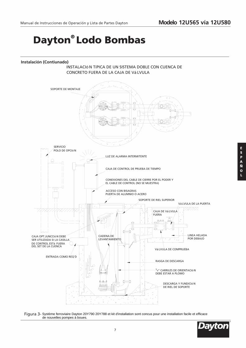
INSTALACIó N TíPICA DE UN SISTEMA DOBLE CON CUENCA DECONCRETO FUERA DE LA CAJA DE Vá LVULA
SOPORTE DE MONTAJE
SERVICIOPOLO DE OPCIó N
LUZ DE ALARMA INTERMITENTE
CAJA DE CONTROL DE PRUEBA DE TIEMPO
CONEXIONES DEL CABLE DE CIERRE POR EL PODER YEL CABLE DE CONTROL (NO SE MUESTRA)
CAJA DE Vá LVULAFUERA
Vá LVULA DE LA PUERTA
ACCESO CON BISAGRASPUERTA DE ALUMNIO O ACERO
CAJA OPT.JUNCCIó N DEBESER UTILIZADA SI LA CASILLADE CONTROL ESTá FUERADEL SET DE LA CUENCA
ENTRADA COMO REQ D
SOPORTE DE RIEL SUPERIOR
LíNEA HELADAPOR DEBAJO
Vá LVULA DE COMPRUEBA
RASGA DE DESCARGA
34" CARRILES DE ORIENTACIó N
DEBE ESTAR A PLOMO
DESCARGA Y FUNDICIó NDE RIEL DE SOPORTE
CADENA DELEVANTAMIENTO
Modelo 12U565 vía 12U580
R
Système ferroviaire Dayton 20Y790 20Y788 et kit d'installation sont concus pour une installation facile et efficace de nouvelles pompes à boues.
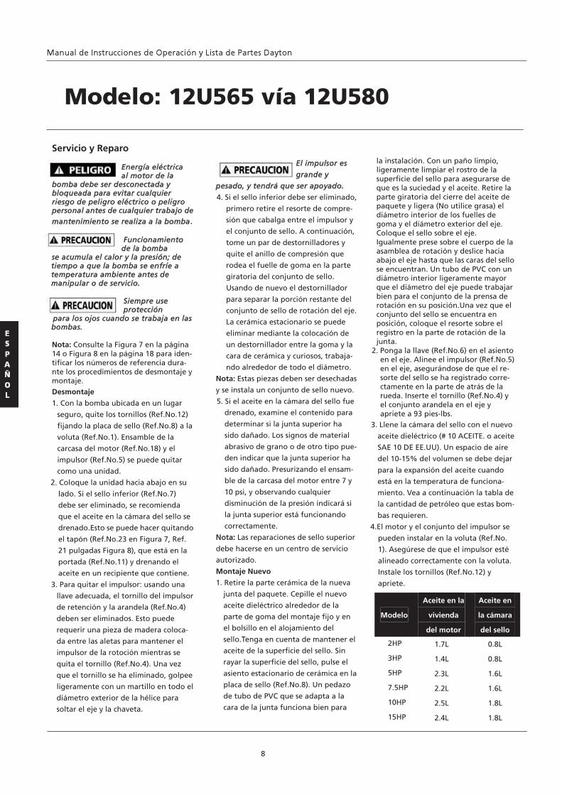
Servicio y Reparo
Energía eléctrica al motor de la
bomba debe ser desconectada y bloqueada para evitar cualquier riesgo de peligro eléctrico o peligro personal antes de cualquier trabajo de mantenimiento se realiza a la bomba.
Funcionamiento de la bomba
se acumula el calor y la presión; de tiempo a que la bomba se enfríe a temperatura ambiente antes de manipular o de servicio.
Siempre use protección
para los ojos cuando se trabaja en las bombas. Nota: Consulte la Figura 7 en la página 14 o Figura 8 en la página 18 para iden- tificar los números de referencia dura- nte los procedimientos de desmontaje y montaje. Desmontaje
1. Con la bomba ubicada en un lugar
seguro, quite los tornillos (Ref.No.12)
fijando la placa de sello (Ref.No.8) a la
voluta (Ref.No.1). Ensamble de la
carcasa del motor (Ref.No.18) y el
impulsor (Ref.No.5) se puede quitar
como una unidad.
2. Coloque la unidad hacia abajo en su
lado. Si el sello inferior (Ref.No.7)
debe ser eliminado, se recomienda
que el aceite en la cámara del sello se
drenado.Esto se puede hacer quitando
el tapón (Ref.No.23 en Figura 7, Ref.
21 pulgadas Figura 8), que está en la
portada (Ref.No.11) y drenando el
aceite en un recipiente que contiene.
3. Para quitar el impulsor: usando una
llave adecuada, el tornillo del impulsor
de retención y la arandela (Ref.No.4)
deben ser eliminados. Esto puede
requerir una pieza de madera coloca-
da entre las aletas para mantener el
impulsor de la rotoción mientras se
quita el tornillo (Ref.No.4). Una vez
que el tornillo se ha eliminado, golpee
ligeramente con un martillo en todo el
diámetro exterior de la hélice para
soltar el eje y la chaveta.
El impulsor es
grande y
pesado, y tendrá que ser apoyado.
4. Si el sello inferior debe ser eliminado,
primero retire el resorte de compre-
sión que cabalga entre el impulsor y
el conjunto de sello. A continuación,
tome un par de destornilladores y
quite el anillo de compresión que
rodea el fuelle de goma en la parte
giratoria del conjunto de sello.
Usando de nuevo el destornillador
para separar la porción restante del
conjunto de sello de rotación del eje.
La cerámica estacionario se puede
eliminar mediante la colocación de
un destornillador entre la goma y la
cara de cerámica y curiosos, trabaja-
ndo alrededor de todo el diámetro.
Nota: Estas piezas deben ser desechadas
y se instala un conjunto de sello nuevo.
5. Si el aceite en la cámara del sello fue
drenado, examine el contenido para
determinar si la junta superior ha
sido dañado. Los signos de material
abrasivo de grano o de otro tipo pue-
den indicar que la junta superior ha
sido dañado. Presurizando el ensam-
ble de la carcasa del motor entre 7 y
10 psi, y observando cualquier
disminución de la presión indicará si
la junta superior está funcionando
correctamente.
Nota: Las reparaciones de sello superior
debe hacerse en un centro de servicio
autorizado.
Montaje Nuevo
1. Retire la parte cerámica de la nueva
junta del paquete. Cepille el nuevo
aceite dieléctrico alrededor de la
parte de goma del montaje fijo y en
el bolsillo en el alojamiento del
sello.Tenga en cuenta de mantener el
aceite de la superficie del sello. Sin
rayar la superficie del sello, pulse el
asiento estacionario de cerámica en la
placa de sello (Ref.No.8). Un pedazo
de tubo de PVC que se adapta a la
cara de la junta funciona bien para
la instalación. Con un paño limpio, ligeramente limpiar el rostro de la superficie del sello para asegurarse de que es la suciedad y el aceite. Retire la parte giratoria del cierre del aceite de paquete y ligera (No utilice grasa) el diámetro interior de los fuelles de goma y el diámetro exterior del eje. Coloque el sello sobre el eje. Igualmente prese sobre el cuerpo de la asamblea de rotación y deslice hacia abajo el eje hasta que las caras del sello se encuentran. Un tubo de PVC con un diámetro interior ligeramente mayor que el diámetro del eje puede trabajar bien para el conjunto de la prensa de rotación en su posición.Una vez que el conjunto del sello se encuentra en posición, coloque el resorte sobre el registro en la parte de rotación de la junta.
2. Ponga la llave (Ref.No.6) en el asiento en el eje. Alinee el impulsor (Ref.No.5) en el eje, asegurándose de que el re- sorte del sello se ha registrado corre- ctamente en la parte de atrás de la rueda. Inserte el tornillo (Ref.No.4) y el conjunto arandela en el eje y apriete a 93 pies-lbs.
3. Llene la cámara del sello con el nuevo
aceite dieléctrico (# 10 ACEITE. o aceite
SAE 10 DE EE.UU). Un espacio de aire
del 10-15% del volumen se debe dejar
para la expansión del aceite cuando
está en la temperatura de funciona-
miento. Vea a continuación la tabla de
la cantidad de petróleo que estas bom-
bas requieren.
4.El motor y el conjunto del impulsor se
pueden instalar en la voluta (Ref.No.
1). Asegúrese de que el impulsor esté
alineado correctamente con la voluta.
Instale los tornillos (Ref.No.12) y
apriete.
8
Modelo: 12U565 vía 12U580
Modelo
Aceite en la
vivienda
del motor
Aceite en
la cámara
del sello
2HP 1.7L 0.8L
3HP 1.4L 0.8L
5HP 2.3L 1.6L
7.5HP 2.2L 1.6L
10HP 2.5L 1.8L
15HP 2.4L 1.8L
ESTATOR
CABLE DEALIMENTACIó N
CABLE DECONTROL
MACETASRESINA
BW
OR
B W
OR
TORNILLODE TIERRA
R W B
R(T
1)
W(T
2)
B(T
3)
GG
CALOR SENSORDE ESTATOR
ELECTRODE
SONDA DE PRUEBA DE RESISTENCIADE UBICACIó N PELIGROSA SOLO
230 VOLT -UNA FASE
CONECTORES
BW
OR
B W
OR
R W B
GG
ELECTRODE
230 VOLT -TRES FASES
T1T7
T2T8
T3T9
T4T5
T6
BW
OR
B W
OR
R W B
GG
ELECTRODE
460 VOLT -TRES FASES
T1
T4
T2 T3
T7 T5 T8 T6 T9
BW
OR R W BGG BW
OR
G BW
OR
GR W BG R W BG
CABLE DECONTROL
CABLE DECONTROL
CABLE DEALIMENTACIó N
CABLE DEALIMENTACIó N
CONECTORES CONECTORES
MACETASRESINA
MACETASRESINA
TORNILLODE TIERRA
TORNILLODE TIERRA
ESTATOR ESTATORCALOR SENSORDE ESTATORSONDA DE PRUEBA DE RESISTENCIADE UBICACIó N PELIGROSA SOLO
CALOR SENSORDE ESTATORSONDA DE PRUEBA DE RESISTENCIADE UBICACIó N PELIGROSA SOLO
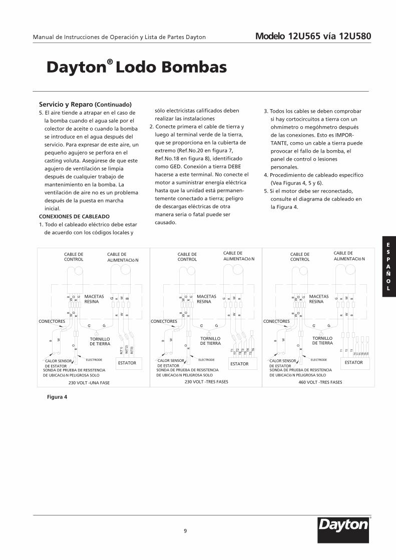
Servicio y Reparo (Continuado) 5. El aire tiende a atrapar en el caso de
la bomba cuando el agua sale por el
colector de aceite o cuando la bomba
se introduce en el agua después del
servicio. Para expresar de este aire, un
pequeño agujero se perfora en el
casting voluta. Asegúrese de que este
agujero de ventilación se limpia
después de cualquier trabajo de
mantenimiento en la bomba. La
ventilación de aire no es un problema
después de la puesta en marcha
inicial.
CONEXIONES DE CABLEADO
1. Todo el cableado eléctrico debe estar
de acuerdo con los códigos locales y
sólo electricistas calificados deben
realizar las instalaciones
2. Conecte primera el cable de tierra y
luego al terminal verde de la tierra,
que se proporciona en la cubierta de
extremo (Ref.No.20 en figura 7,
Ref.No.18 en figura 8), identificado
como GED. Conexión a tierra DEBE
hacerse a este terminal. No conecte el
motor a suministrar energía eléctrica
hasta que la unidad está permanen-
temente conectado a tierra; peligro
de descargas eléctricas de otra
manera seria o fatal puede ser
causado.
3. Todos los cables se deben comprobar
si hay cortocircuitos a tierra con un
ohmímetro o megóhmetro después
de las conexiones. Esto es IMPOR-
TANTE, como un cable a tierra puede
provocar el fallo de la bomba, el
panel de control o lesiones
personales.
4. Procedimiento de cableado específico
(Vea Figuras 4, 5 y 6).
5. Si el motor debe ser reconectado,
consulte el diagrama de cableado en
la Figura 4.
9
Figura 4
Dayton® Lodo Bombas
Modelo 12U565 vía 12U580
R
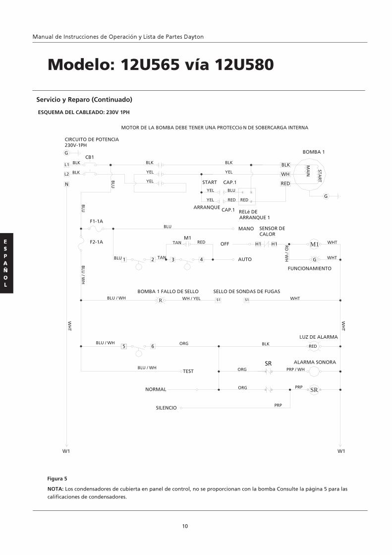
10
ESQUEMA DEL CABLEADO: 230V 1PH
Servicio y Reparo (Continuado)
Figura 5
Modelo: 12U565 vía 12U580
NOTA: Los condensadores de cubierta en panel de control, no se proporcionan con la bomba Consulte la página 5 para las
calificaciones de condensadores.
L1
L2
CB1
1 5
2
BLK
WH
RED
G
G
N
1 2 3 4
H1 H1
G
M1
R S1 S1
5 6 RED
SR
4 2
4 3 1 5
CIRCUITO DE POTENCIA230V-1PH
BLK
BLK
BLK
YEL
YEL
M1
BLK
YEL
BOMBA 1
MA
IN
STAR
TBLU START CAP.1
ARRANQUE CAP.1 RELé DEARRANQUE 1
YEL
YEL
BLU
RED RED
BLU
F1-1A
F2-1A
BLU
BLU
TAN
TAN RED
MANO SENSOR DECALOR
OFF
AUTO
BLU
/ WH
RD
/ WH
WHT
WHT
FUNCIONAMIENTO
BLU / WH
BOMBA 1 FALLO DE SELLOWH / YEL
SELLO DE SONDAS DE FUGASWHT
WH
T
BLU / WH
BLU / WH
ORG
TEST
NORMAL
SILENCIO
ORG
ORG
BLK
SR
LUZ DE ALARMA
ALARMA SONORAPRP / WH
PRP
PRP
W1 W1
MOTOR DE LA BOMBA DEBE TENER UNA PROTECCIó N DE SOBERCARGA INTERNA
WH
T
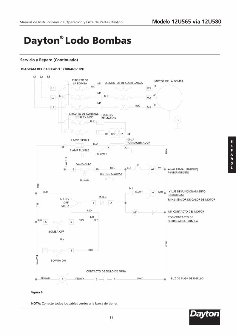
DIAGRAM DEL CABLEADO : 230&460V 3PH
11
NOTA: Conecte todos los cables verdes a la barra de tierra.
Figura 6
Servicio y Reparo (Continuado)
Dayton® Lodo Bombas
B
W
RM1
M2
M3
M1
M1
M1 ELEMENTOS DE SOBRECARGAMOTOR DE LA BOMBA
L1
L2
L3
L2L1 L3
H1 H3 H2 H4
9 10
FAL
1 2
Y
65
7 8
R 3 4
CIRCUITO DELA BOMBA
CIRCUITO DE CONTROLROTO 15 AMP
FUSIBLESPRIMARIOS
1 AMP FUSIBLE
XF
100VATRANSFORMADOR
X1 X2
AGUA ALTA
TEST DE ALARMA
AL-ALARMA LUZ(ROJO)F-INTERMITENTE
Y-LUZ DE FUNCIONAMIENTO(AMARILLO)
M.H.S-SENSOR DE CALOR DE MOTOR
M1-CONTACTO DEL MOTOR
TOC-CONTACTO DESOBRECARGA TéRMICA
LUZ DE FUGA DE R-SELLO
M1
MANOOFF
AUTO
M.H.S.
M1
M1
BOMBA OFF
BOMBA ON
CONTACTO DE SELLO DE FUGA
BLU
BLU/WH
BLU
BLU
BLU
BLU
/WH
BLU/WH YEL/WH WHT
WH
TW
HT
WHTBLKORGB
LU/W
H
BLU
BLU/WH
WHTRD/WH
RED
REDBRN
BRN
RED
BLK
BLK
BLK
BLK
BLK
G
1 AMP FUSIBLE
Modelo 12U565 vía 12U580
R

Luz amarillo permanece
encendida
1. Interruptor H-O-A puede estar en la posición de la mano
2. Interruptor de nivel de control puede haber fallado la bomba causando a seguir funcionando cuando el agua estápor debajo de un menor control.
3. El asamblea molino se obstruye causan-
do que la bomba funcione con una capacidad muy reducida.
4. Válvula de compuerta o válvula de
retención puede estar obstruidas causando el flujo de la bomba bajo.
5. Bomba de aire puede ser registrada.
La luz roja se enciende en
el cuadro de control 1. Esto indica un poco de agua se ha
filtrado por el sello inferior y ha entradoen la cámara del sello y se puso en contacto con la sonda del electrodo.
1. Vuelva a colocar el sello inferior
1. Vuelva a colocar la bomba o limpie la cuenca como sea necesario para proporcionar suficiente espacio para flotar.
2. Desconecte el control de nivel. Establezca ohmiómetro para un rango bajo, como 100ohmios escala completa y conecte a los cables de control de nivel. Accione el control de nivel de forma manual y comprobar que ohmímetro muestra cero ohmios para cerrar interruptor y la escala completa para el interruptor abierto (Interruptor de flotador).
3. Compruebe montaje molino de la libertad de funcionamiento, la seguridad y el estado. Limpio la cavidad y la entrada de cualquier obstrucción.
4. Extraiga y examine la válvula de retención para la correcta instalación y la libertad de funcionamiento.
5. Afloje la unión ligeramente para permitir
que el aire atrapado escape. Verifique que el nivel de desconexión de interruptor se ajusta de modo que la cavidad del impulsor es siempre inundada. Limpie orificio de ventilación.
Síntoma CCausa (s) Posible (s) Acción Correctiva
12
Modelo: 12U565 vía 12U580Gráfico de Soluciones de Problema
Siempre desconecte la bomba de la fuente de alimentación eléctrica ante el manejo. Si el sistema tiene el fallo d e operación adecuada, lea las instrucciones y ejecute las recomendaciones de mantenimiento con cuidado. Si
los problemas operativos persisten, el gráfico siguiente puede ayudarle identificar y corregirlos.
Disparos por sobrecarga en la caja de control y alarma sonora o una luz intermitente roja se enciende debido a alto nivel de agua en la cuenca
1. Impulsor de molino se parcialmente obstruye con algunos objetos extraños
2. Componente en la caja de control
puede ser defectuoso. 3. La bomba ha dañado un poco.
1. Compruebe impulsor triturador para la libertad de funcionamiento, la seguridad y el estado. Limpie el impulsor de cavidad y la entrada de cualquier obstrucción.
2. Marque la casilla de control, si es necesario repararla.
3. Revise la bomba, si es necesario repárela.
Modelo 12U565 vía 12U580
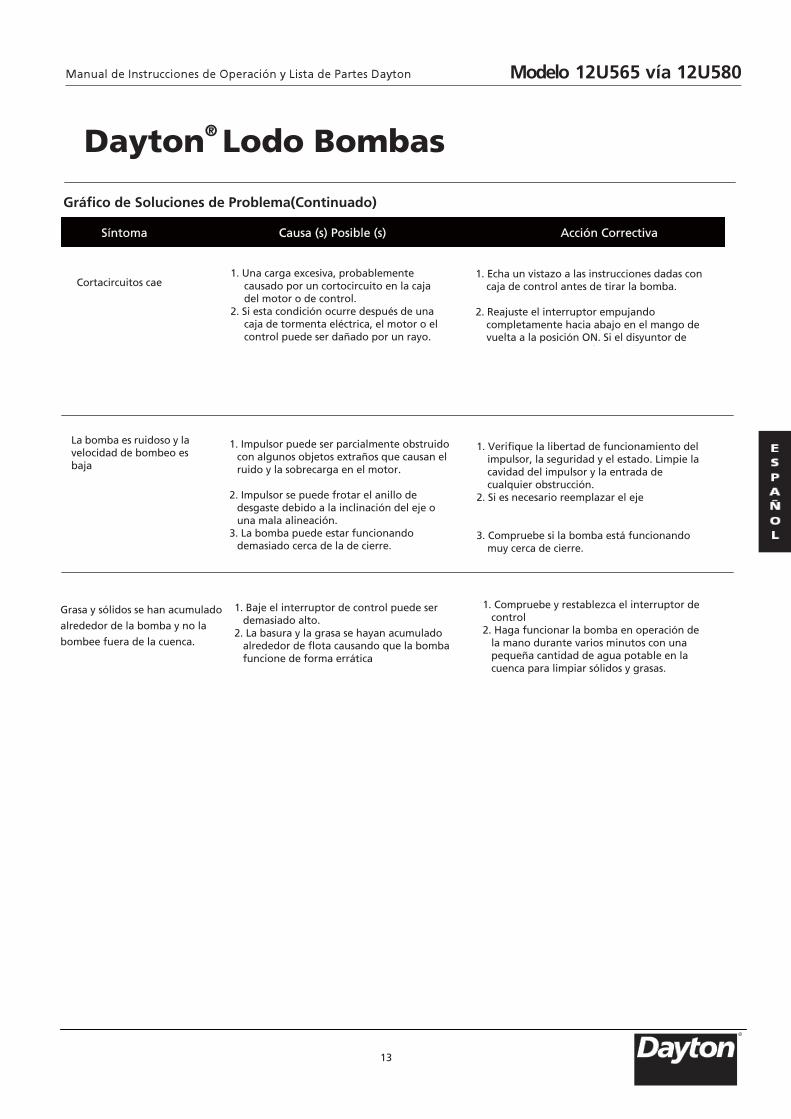
Gráfico de Soluciones de Problema(Continuado)
13
Síntoma CCausa (s) Posible (s) Acción Correctiva
Dayton® Lodo Bombas
Cortacircuitos cae 1. Una carga excesiva, probablemente
causado por un cortocircuito en la caja del motor o de control.
2. Si esta condición ocurre después de una caja de tormenta eléctrica, el motor o el control puede ser dañado por un rayo.
1. Echa un vistazo a las instrucciones dadas con caja de control antes de tirar la bomba.
2. Reajuste el interruptor empujando
completamente hacia abajo en el mango de vuelta a la posición ON. Si el disyuntor de
d i di
La bomba es ruidoso y la velocidad de bombeo es baja
1. Impulsor puede ser parcialmente obstruido con algunos objetos extraños que causan el ruido y la sobrecarga en el motor.
2. Impulsor se puede frotar el anillo de
desgaste debido a la inclinación del eje o una mala alineación.
3. La bomba puede estar funcionando demasiado cerca de la de cierre.
1. Verifique la libertad de funcionamiento del impulsor, la seguridad y el estado. Limpie la cavidad del impulsor y la entrada de cualquier obstrucción.
2. Si es necesario reemplazar el eje 3. Compruebe si la bomba está funcionando
muy cerca de cierre.
Grasa y sólidos se han acumulado
alrededor de la bomba y no la
bombee fuera de la cuenca.
1. Baje el interruptor de control puede ser demasiado alto.
2. La basura y la grasa se hayan acumulado alrededor de flota causando que la bomba funcione de forma errática
1. Compruebe y restablezca el interruptor de control
2. Haga funcionar la bomba en operación de la mano durante varios minutos con una pequeña cantidad de agua potable en la cuenca para limpiar sólidos y grasas.
Especificaciones y Manuales de Piezas de Dayton Modelo 12U565 vía 12U580
R

v
14
Figura 7- Las partes de reparación para la ilustración Modelos: 12U565 vía 12U576
4
6
5
7
8
12
23
14
15
19
23
20
19
1
2
3
7
9
10
11
13
16
17
18
13
21
22
Para Reparar Piezas, llame 1-800-323-0620
24 horas al día – 365 días al año
Por favor, ofreza la información siguiente: -Número de Modelo -Número de Serie(Si hay) -Descripción y número de pieza como se muestra en la lista de piezas.
Modelo 12U565 vía 12U580
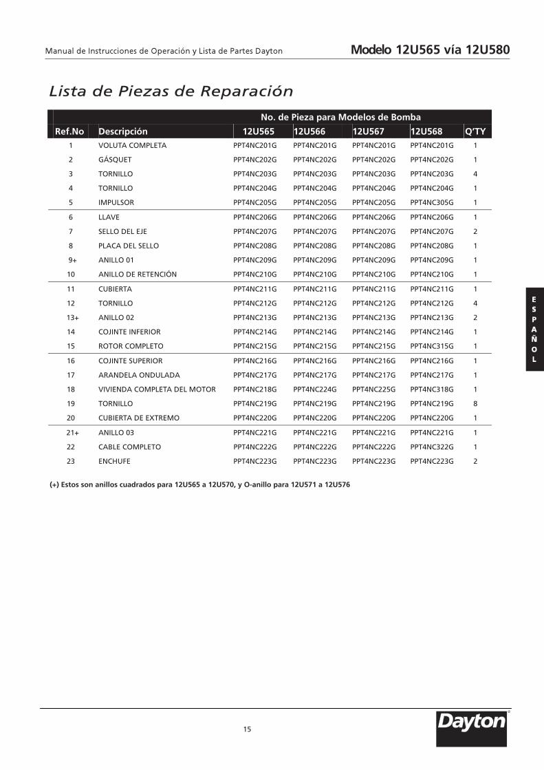
Lista de Piezas de Reparación
15
No. de Pieza para Modelos de Bomba
Ref.No. Descripción 12U565 12U566 12U567 12U568 Q’TY1 VOLUTA COMPLETA PPT4NC201G PPT4NC201G PPT4NC201G PPT4NC201G 1
2 GÁSQUET PPT4NC202G PPT4NC202G PPT4NC202G PPT4NC202G 1
3 TORNILLO PPT4NC203G PPT4NC203G PPT4NC203G PPT4NC203G 4
4 TORNILLO PPT4NC204G PPT4NC204G PPT4NC204G PPT4NC204G 1
5 IMPULSOR PPT4NC205G PPT4NC205G PPT4NC205G PPT4NC305G 1
6 LLAVE PPT4NC206G PPT4NC206G PPT4NC206G PPT4NC206G 1
7 SELLO DEL EJE PPT4NC207G PPT4NC207G PPT4NC207G PPT4NC207G 2
8 PLACA DEL SELLO PPT4NC208G PPT4NC208G PPT4NC208G PPT4NC208G 1
9+ ANILLO 01 PPT4NC209G PPT4NC209G PPT4NC209G PPT4NC209G 1
10 ANILLO DE RETENCIÓN PPT4NC210G PPT4NC210G PPT4NC210G PPT4NC210G 1
11 CUBIERTA PPT4NC211G PPT4NC211G PPT4NC211G PPT4NC211G 1
12 TORNILLO PPT4NC212G PPT4NC212G PPT4NC212G PPT4NC212G 4
13+ ANILLO 02 PPT4NC213G PPT4NC213G PPT4NC213G PPT4NC213G 2
14 COJINTE INFERIOR PPT4NC214G PPT4NC214G PPT4NC214G PPT4NC214G 1
15 ROTOR COMPLETO PPT4NC215G PPT4NC215G PPT4NC215G PPT4NC315G 1
16 COJINTE SUPERIOR PPT4NC216G PPT4NC216G PPT4NC216G PPT4NC216G 1
17 ARANDELA ONDULADA PPT4NC217G PPT4NC217G PPT4NC217G PPT4NC217G 1
18 VIVIENDA COMPLETA DEL MOTOR PPT4NC218G PPT4NC224G PPT4NC225G PPT4NC318G 1
19 TORNILLO PPT4NC219G PPT4NC219G PPT4NC219G PPT4NC219G 8
20 CUBIERTA DE EXTREMO PPT4NC220G PPT4NC220G PPT4NC220G PPT4NC220G 1
21+ ANILLO 03 PPT4NC221G PPT4NC221G PPT4NC221G PPT4NC221G 1
22 CABLE COMPLETO PPT4NC222G PPT4NC222G PPT4NC222G PPT4NC322G 1
23 ENCHUFE PPT4NC223G PPT4NC223G PPT4NC223G PPT4NC223G 2
(+) Estos son anillos cuadrados para 12U565 a 12U570, y O-anillo para 12U571 a 12U576
Modelo 12U565 vía 12U580
R
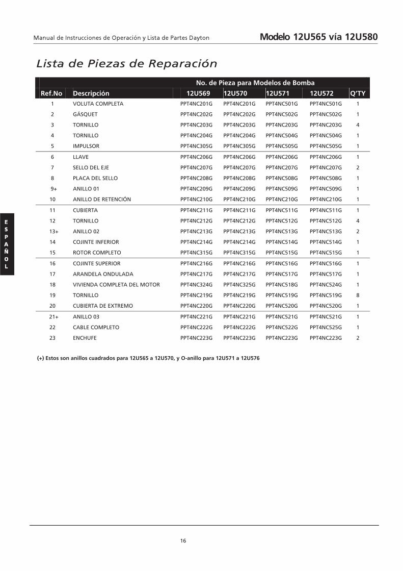
Lista de Piezas de Reparación
16
No. de Pieza para Modelos de Bomba
Ref.No. Descripción 12U569 12U570 12U571 12U572 Q’TY1 VOLUTA COMPLETA PPT4NC201G PPT4NC201G PPT4NC501G PPT4NC501G 1
2 GÁSQUET PPT4NC202G PPT4NC202G PPT4NC502G PPT4NC502G 1
3 TORNILLO PPT4NC203G PPT4NC203G PPT4NC203G PPT4NC203G 4
4 TORNILLO PPT4NC204G PPT4NC204G PPT4NC504G PPT4NC504G 1
5 IMPULSOR PPT4NC305G PPT4NC305G PPT4NC505G PPT4NC505G 1
6 LLAVE PPT4NC206G PPT4NC206G PPT4NC206G PPT4NC206G 1
7 SELLO DEL EJE PPT4NC207G PPT4NC207G PPT4NC207G PPT4NC207G 2
8 PLACA DEL SELLO PPT4NC208G PPT4NC208G PPT4NC508G PPT4NC508G 1
9+ ANILLO 01 PPT4NC209G PPT4NC209G PPT4NC509G PPT4NC509G 1
10 ANILLO DE RETENCIÓN PPT4NC210G PPT4NC210G PPT4NC210G PPT4NC210G 1
11 CUBIERTA PPT4NC211G PPT4NC211G PPT4NC511G PPT4NC511G 1
12 TORNILLO PPT4NC212G PPT4NC212G PPT4NC512G PPT4NC512G 4
13+ ANILLO 02 PPT4NC213G PPT4NC213G PPT4NC513G PPT4NC513G 2
14 COJINTE INFERIOR PPT4NC214G PPT4NC214G PPT4NC514G PPT4NC514G 1
15 ROTOR COMPLETO PPT4NC315G PPT4NC315G PPT4NC515G PPT4NC515G 1
16 COJINTE SUPERIOR PPT4NC216G PPT4NC216G PPT4NC516G PPT4NC516G 1
17 ARANDELA ONDULADA PPT4NC217G PPT4NC217G PPT4NC517G PPT4NC517G 1
18 VIVIENDA COMPLETA DEL MOTOR PPT4NC324G PPT4NC325G PPT4NC518G PPT4NC524G 1
19 TORNILLO PPT4NC219G PPT4NC219G PPT4NC519G PPT4NC519G 8
20 CUBIERTA DE EXTREMO PPT4NC220G PPT4NC220G PPT4NC520G PPT4NC520G 1
21+ ANILLO 03 PPT4NC221G PPT4NC221G PPT4NC521G PPT4NC521G 1
22 CABLE COMPLETO PPT4NC222G PPT4NC222G PPT4NC522G PPT4NC525G 1
23 ENCHUFE PPT4NC223G PPT4NC223G PPT4NC223G PPT4NC223G 2
(+) Estos son anillos cuadrados para 12U565 a 12U570, y O-anillo para 12U571 a 12U576
Modelo 12U565 vía 12U580

Lista de Piezas de Reparación
17
No. de Pieza para Modelos de Bomba
Ref.No. Descripción 12U573 12U574 12U575 12U576 Q’TY1 VOLUTA COMPLETA PPT4NC501G PPT4NC501G PPT4NC501G PPT4NC501G 1
2 GÁSQUET PPT4NC502G PPT4NC502G PPT4NC502G PPT4NC502G 1
3 TORNILLO PPT4NC203G PPT4NC203G PPT4NC203G PPT4NC203G 4
4 TORNILLO PPT4NC504G PPT4NC504G PPT4NC504G PPT4NC504G 1
5 IMPULSOR PPT4NC505G PPT4NC705G PPT4NC705G PPT4NC705G 1
6 LLAVE PPT4NC206G PPT4NC206G PPT4NC206G PPT4NC206G 1
7 SELLO DEL EJE PPT4NC207G PPT4NC207G PPT4NC207G PPT4NC207G 2
8 PLACA DEL SELLO PPT4NC508G PPT4NC508G PPT4NC508G PPT4NC508G 1
9+ ANILLO 01 PPT4NC509G PPT4NC509G PPT4NC509G PPT4NC509G 1
10 ANILLO DE RETENCIÓN PPT4NC210G PPT4NC210G PPT4NC210G PPT4NC210G 1
11 CUBIERTA PPT4NC511G PPT4NC511G PPT4NC511G PPT4NC511G 1
12 TORNILLO PPT4NC512G PPT4NC512G PPT4NC512G PPT4NC512G 4
13+ ANILLO 02 PPT4NC513G PPT4NC513G PPT4NC513G PPT4NC513G 2
14 COJINTE INFERIOR PPT4NC514G PPT4NC514G PPT4NC514G PPT4NC514G 1
15 ROTOR COMPLETO PPT4NC515G PPT4NC715G PPT4NC715G PPT4NC715G 1
16 COJINTE SUPERIOR PPT4NC516G PPT4NC516G PPT4NC516G PPT4NC516G 1
17 ARANDELA ONDULADA PPT4NC517G PPT4NC517G PPT4NC517G PPT4NC517G 1
18 VIVIENDA COMPLETA DEL MOTOR PPT4NC526G PPT4NC718G PPT4NC724G PPT4NC726G 1
19 TORNILLO PPT4NC519G PPT4NC519G PPT4NC519G PPT4NC519G 8
20 CUBIERTA DE EXTREMO PPT4NC520G PPT4NC520G PPT4NC520G PPT4NC520G 1
21+ ANILLO 03 PPT4NC521G PPT4NC521G PPT4NC521G PPT4NC521G 1
22 CABLE COMPLETO PPT4NC527G PPT4NC722G PPT4NC522G PPT4NC525G 1
23 ENCHUFE PPT4NC223G PPT4NC223G PPT4NC223G PPT4NC223G 2
(+) Estos son anillos cuadrados para 12U565 a 12U570, y O-anillo para 12U571 a 12U576
Modelo 12U565 vía 12U580
R
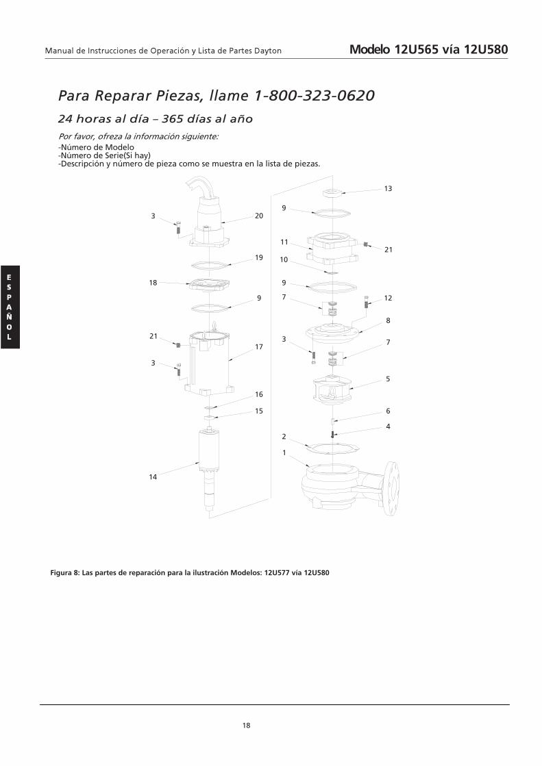
18
Figura 8: Las partes de reparación para la ilustración Modelos: 12U577 vía 12U580
4
6
5
7
8
12
21
13
14
3
21
18
3
1
2
3
7
9
10
11
9
15
16
17
9
19
20
Para Reparar Piezas, llame 1-800-323-0620
24 horas al día – 365 días al año
Por favor, ofreza la información siguiente: -Número de Modelo -Número de Serie(Si hay) -Descripción y número de pieza como se muestra en la lista de piezas.
Modelo 12U565 vía 12U580
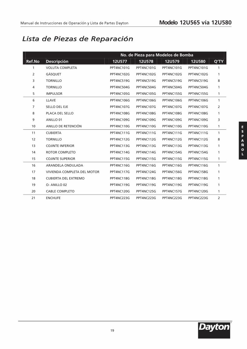
Lista de Piezas de Reparación
19
No. de Pieza para Modelos de Bomba
Ref.No. Descripción 12U577 12U578 12U579 12U580 Q’TY
1 VOLUTA COMPLETA PPT4NC101G PPT4NC101G PPT4NC101G PPT4NC101G 1
1G201CN4TPP G201CN4TPPG201CN4TPPG201CN4TPP TEUQSÁG 2
8G915CN4TPP G915CN4TPPG915CN4TPPG915CN4TPP OLLINROT 3
1G405CN4TPP G405CN4TPPG405CN4TPPG405CN4TPP OLLINROT 4
1G551CN4TPP G551CN4TPPG501CN4TPPG501CN4TPP ROSLUPMI 5
6 LLA 1G601CN4TPP G601CN4TPPG601CN4TPPG601CN4TPP EV
2G701CN4TPP G701CN4TPPG701CN4TPPG701CN4TPP EJE LED OLLES 7
8 PLACA 1G801CN4TPP G801CN4TPPG801CN4TPPG801CN4TPP OLLES LED
9 A 3G901CN4TPP G901CN4TPPG901CN4TPPG901CN4TPP 10 OLLIN
10 ANILLO DE RETENCIÓN PPT4NC110G PPT4NC110G PPT4NC110G PPT4NC110G 1
11 CUBIERTA 1G111CN4TPP G111CN4TPPG111CN4TPPG111CN4TPP
8G211CN4TPP G211CN4TPPG211CN4TPPG211CN4TPP OLLINROT 21
1G311CN4TPP G311CN4TPPG311CN4TPPG311CN4TPP ROIREFNI ETNIJOC 31
1G451CN4TPP G451CN4TPPG411CN4TPPG411CN4TPP OTELPMOC ROTOR 41
1G511CN4TPP G511CN4TPPG511CN4TPPG511CN4TPP ROIREPUS ETNIJOC 51
16 ARANDELA ONDULADA PPT4NC116G PPT4NC116G PPT4NC116G PPT4NC116G 1
17 VIVIENDA COMPLETA DEL MOTOR PPT4NC117G PPT4NC124G PPT4NC156G PPT4NC158G 1
18 CUBIERTA DEL EXTREMO PPT4NC118G PPT4NC118G PPT4NC118G PPT4NC118G 1
19 O- A 1G911CN4TPP G911CN4TPPG911CN4TPPG911CN4TPP 20 OLLIN
20 CAB 1G021CN4TPP G751CN4TPPG521CN4TPPG021CN4TPP OTELPMOC EL
21 ENCH 2G322CN4TPP G322CN4TPPG322CN4TPPG322CN4TPP EFU
Modelo 12U565 vía 12U580
R
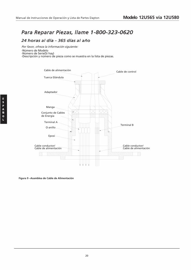
20
Figura 9 –Asamblea de Cable de Alimentación
Para Reparar Piezas, llame 1-800-323-0620
24 horas al día – 365 días al año
Por favor, ofreza la información siguiente: -Número de Modelo -Número de Serie(Si hay) -Descripción y número de pieza como se muestra en la lista de piezas.
Cable de alimentación
Tuerca Glándula
Adaptador
Manga
Conjunto de Cablesde Energía
O-anillo
Terminal A
Epoxi
Cable conductor/Cable de alimentación
Cable conductor/Cable de alimentación
Terminal B
Cable de control
Modelo 12U565 vía 12U580
GARANTÍA LIMITADA GARANTÍA LIMITADA DE DAYTON POR UN AÑO DAYTON LODO BOMBAS, MODELOS INDICADOS EN ESTE MANUAL, QUE ESTÁ
GARANTIZADO POR DAYTON ELECTRIC MFG. CO. (DAYTON)AL USUARIO ORIGINAL CONTRA DEFECTOS EN MATERIALES Y MANO DE
OBRA CUANDO SE LES SOMETE A USO NORMAL, POR UN AÑO A PARTIR DE LA FECHA DE COMPRA. CUALQUIER PARTE QUE SE
ENCUENTRE DEFECTUOSA, TANTO EN EL MATERIAL COMO EN LA MANO DE OBRA, Y SEA DEVUELTA A UN LUGAR DE SERVICIO
AUTORIZADO DESIGNADO POR DAYTON, CON LOS COSTOS DE ENVÍO PAGADOS POR ADELANTADO, SERÁ REPARADA O
REEMPLAZADA A LA DISCRECIÓN DE DAYTON COMO REMEDIO EXCLUSIVO. PARA OBTENER LA INFORMACIÓN SOBRE LOS
PROCEDIMIENTOS DE RECLAMAR CUBIERTOS EN LA GARANTÍA LIMITADA VEA ATENCION OPORTUNA A CONTINUACIÓN. ESTA
GARANTÍA LIMITADA CONFIERE A LOS COMPRADORES DERECHOS LEGALES ESPECÍFICOS QUE VARÍAN DE JURISDICCIÓN A
JURISDICCIÓN.
LIMITES DE RESPONSABILIDAD. HASTA EL PUNTO QUE LAS LEYES APLICABLES LO PERMITAN, LA RESPONSABILIDAD DE DAYTON
POR LOS DAÑOS EMERGENTES O INCIDENTALES ESTÁ EXPRESAMENTE EXCLUIDA. LA RESPONSABILIDAD DE DAYTON
EXPRESAMENTE ESTÁ LIMITADA Y NO PUEDE EXCEDER EL PRECIO DE COMPRA PAGADO POR EL ARTÍCULO.
EXCLUSIÓN DE RESPONSABILIDAD DE LA GARANTIA. UN ESFUERZO DILIGENTE SE HA HECHO PARA PROPORCIONAR
INFORMACIÓN SOBRE EL PRODUCTOS EN ESTA LITERATURA EN FORMA APROPIADA; SIN EMBARGO, TAL INFORMACIÓN Y LAS
ILUSTRACIONES Y DESCRIPCIONES TIENEN COMO ÚNICO PROPÓSITO LA IDENTIFICACIÓN DEL PRODUCTO Y NO EXPRESAN NI
IMPLICAN GARANTÍA DE QUE LOS PRODUCTOS SON VENDIBLES O ADECUADOS PARA UN PROPÓSITO EN PARTICULAR O QUE SE
AJUSTAN NECESARIAMENTE A LAS ILUSTRACIONES O DESCRIPCIONES. CON EXCEPCIÓN DE LO QUE SE ESTABLECE A CONTINUACIÓN,
DAYTON NO HACE NI AUTORIZA NINGUNA GARANTÍA O AFIRMACIÓN DE HECHO, EXPRESA O IMPLÍCITA, QUE NO SEA ESTIPULADA
EN LA GARANTIA LIMITADA ANTERIOR.
Consejo Técnico y Recomendaciones, Exclusiones de Responsabilidad. A pesar de las prácticas, negociaciones o usos comerciales
realizados previamente, las ventas no deberán incluir el suministro de consejo técnico o asistencia o diseño del sistema. Dayton no
asume ninguna obligación o responsabilidad por recomendaciones, opiniones o consejos no autorizados sobre la elección,
instalación o uso de los productos.
ADAPTACIÓN DEL PRODUCTO. Muchas jurisdicciones tienen códigos o reglamentos que rigen las ventas, la construcción, la
instalación, y el uso del producto para ciertos propósitos que pueden variar con respecto a los aplicables ea las zonas vecinas. Si bien
los intentos están hechos para asegurarse que los productos de Dayon cumplan con dichos códigos, Dayon no puede garantizar su
conformidad y no puede hacerse responsable por la forma en que su producto se instala o usa. Antes de comprar y usar el producto,
revise su aplicación y todos los códigos y regulaciones nacionales ylocales aplicables y asegúrese que el producto, la instalación y el
uso los cumplan.
Ciertos aspectos de limitación de responsabilidad no se aplican a los productos del consumidor; es decir (a) algunas jurisidicciones no
permiten la exclusión o la limitación de daños incidentales o emergentes, de modo que las limitaciónes o exclusiónes anteriores
puede que no se apliquen en su caso; (b) también, algunas jurisdicciones no permiten limitar el tiempo que una garantía implicita
dura, por lo tanto, la limitación anterior puede que no se aplique en su caso; y (c) por ley, durante el período que dura esta
GARANTÍA LIMITADA,las garantías implicitas de comercialización o de adecuación para un propósito en particular aplicables a los
productos del consumidor comprados por consumidores no pueden ser excluidas o no pueden excluirse de la responsabilidad en
alguna otra forma.
ATENCIÓN OPORTUNA. Se hará un esfuerzo de buena fe para corregir puntualmente, o hacer otros ajustes, con respecto a cualquier
producto que resulte defectuoso dentro de los términos de esta garantía limitada. En el caso de que encuentre un producto
defectuoso y que esté cubierto dentro de los limites de esta garantía haga el favor de escribir primero, o llame, al distribuidor de
quien compró el producto. El distribuidor le dará las instrucciones adicionales. Si no puede resolver el problema en forma
satisfactoria, escriba a Dayton a la dirección a continuación, dando el nombre del distribuidor, su dirección, la fecha y el número de
la factura del distribuidor y describa la naturaleza del defecto. La propiedad del artículo y el riesgo de perdida pasan al comprador
en el momento de la entrega del artículo a la compañia de transporte. Si el producto se daña durante el transporte debe presentar
su reclamo a la compañia de transporte.
21
Dayton® Lodo Bombas
Fabricado para Dayton Electric Mfg. Co., 100 Lake Forest, IL 60045 EE. UU.
Modelo 12U565 vía 12U580
R

Notas
22
Modelo 12U565 vía 12U580

TEMPERATURE …………140°F Intermittent; 104°F en continu
IMPELLEUR………………2 Vane, fermé
TRAITEMENT DE SOLIDES…..3” (76.2.mm) sphérique
SCEAU…………………..TYPE 11, Mécanique double
ENTRÉE DU CABLE……20ft. (6m) du cordon, SOW époxy
Boîter étanche avec oeillet de pression
secondaire pour scheller et réduire la
tension
MATÉRIEL DU JOINT………….....Le carbure de silicium, Céramique, SS
ROULEMENT INFERIEUR……Ligne unique, l’huile lubrifiante à bille,
charge radiale & axiale
ROULEMENT SUPERIEUR…...Ligne unique, l’huile lubrifiante à bille,
charge radiale
VITESSE………………….....…1750 RPM
Obligation……………………Continue
Forme 5S6908 Imprimé en Chine
09439
Version 1
TONE100
05/2013
FORME # 897
Le Manuel du Mode d’Emploi Modèle 12U565 à12U580et des Pièces de Dayton
Veuillez lire minutieusement ce manuel d’opération avant l’assemblage, l’inst-ou le maintien de ce produit. Le respect de toutes les informations de sécurité permet de vous protéger et de protéger les
autres. Assurez-vous de vous conformer aux instructions de sécurité. Tout manquement pour suivre les instructions de sécurité peut causer desles instructions pour la référence future.
Dayton® Pompes à Boue
Description Ces pompes Boue sont conçus pour un pomper des liquides des effluents ou des eaux
usées, non explosives et non corrosives compatible avec le matériel de la pompe de
maquillage, et peut gérer 8% de matières solides par volume. Les pompes comportent une
sonde de fuite d’étanchéité qui peut avertir de l’entrée d’huimiditié, et aider à prévenir le
moteur coûteurx consumé.
Figure 1
Performance
Spécifications
GPM à Pied Total de la Tête Modèle HP
5’ 10’ 15’ 20’ 25’ 30’ 40’ 50’ 60’ 70’ 80’ 90’
Max.
Tête* (Ft.)
12U565 2 385 330 250 170 100 25 -- -- -- -- -- -- 32
12U566 2 385 330 250 170 100 25 -- -- -- -- -- -- 32
12U567 2 385 330 250 170 100 25 -- -- -- -- -- -- 32
12U568 3 482 420 340 275 200 130 -- -- -- -- -- -- 40
12U569 3 482 420 340 275 200 130 -- -- -- -- -- -- 40
12U570 3 482 420 340 275 200 130 -- -- -- -- -- -- 40
12U571 5 710 662 600 505 400 290 75 -- -- -- -- -- 46
12U572 5 710 662 600 505 400 290 75 -- -- -- -- -- 46
12U573 5 710 662 600 505 400 290 75 -- -- -- -- -- 46
12U574 7.5 770 740 700 648 570 475 252 55 -- -- -- -- 54
12U575 7.5 770 740 700 648 570 475 252 55 -- -- -- -- 54
12U576 7.5 770 740 700 648 570 475 252 55 -- -- -- -- 54
(*) Pour convertir en psi, multiplier par gravité spécifique et diviser par 2.31
R
Veuillez lire et conserver ces instructions.
blessures graves et /ou destructions de propriété. Gardez
allation, l’opération
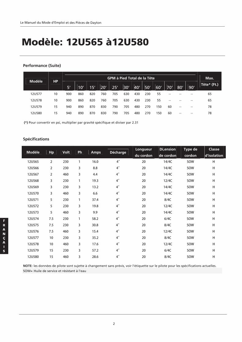
Modèle Hp Volt Ph Amps Décharge Longueur
du cordon
Di,ension
de cordon
Type de
cordon
Classe
d’isolation
Spécifications
2
Performance (Suite)
GPM à Pied Total de la Tête Modèle HP
5’ 10’ 15’ 20’ 25’ 30’ 40’ 50’ 60’ 70’ 80’ 90’
Max.
Tête* (Ft.)
12U577 10 900 860 820 760 705 630 430 230 55 -- -- -- 65
12U578 10 900 860 820 760 705 630 430 230 55 -- -- -- 65
12U579 15 940 890 870 830 790 705 480 270 150 60 -- -- 78
12U580 15 940 890 870 830 790 705 480 270 150 60 -- -- 78
(*) Pour convertir en psi, multiplier par gravité spécifique et diviser par 2.31
NOTE: les données de pilote sont sujette à changement sans prévis, voir l’étiquette sur le pilote pour les spécifications actuelles.
SOW= Huile de service et résistant à l'eau
Modèle: 12U565 à12U580
12U565 2 230 1 16.0 4”
12U580 15 460 3 28.6 4”
12U579 15 230 3 57.2 4”
12U578 10 460 3 17.6 4”
12U577 10 230 3 35.2 4”
12U576 7.5 460 3 15.4 4”
12U575 7.5 230 3 30.8 4”
12U574 7.5 230 1 58.2 4”
12U573 5 460 3 9.9 4”
12U572 5 230 3 19.8 4”
12U566 2 230 3 8.8 4”
12U567 2 460 3 4.4 4”
12U571 5 230 1 37.4 4”
12U570 3 460 3 6.6 4”
12U569 3 230 3 13.2 4”
12U568 3 230 1 19.3 4”
20 14/4C SOW H
20 14/4C SOW H
20 14/4C SOW H
20 12/4C SOW H
20 14/4C SOW H
20 14/4C SOW H
20 8/4C SOW H
20 12/4C SOW H
20 14/4C SOW H
20 6/4C SOW H
20 8/4C SOW H
20 12/4C SOW H
20 8/4C SOW H
20 12/4C SOW H
20 6/4C SOW H
20 8/4C SOW H
Le Manuel du Mode d’Emploi et des Pièces de Dayton

Dayton® Pompes à Boue
3
Spécifications (Suite)
Figure 2-dimensions [en pouces]
Dimensions (en pouces) Matériel de pompe
Model A B C D E H VoluteMoteur de
logement Top Impelleur Arbre
12U565 10 1/2 4 1/2 6 5 5/16 9 28 3/8 CI CI CI CI SS
12U566 10 1/2 4 1/2 6 5 5/16 9 28 3/8 CI CI CI CI SS
12U567 10 1/2 4 1/2 6 5 5/16 9 28 3/8 CI CI CI CI SS
12U568 10 1/2 4 1/2 6 5 5/16 9 28 3/8 CI CI CI CI SS
12U569 10 1/2 4 1/2 6 5 5/16 9 28 3/8 CI CI CI CI SS
12U570 10 1/2 4 1/2 6 5 5/16 9 28 3/8 CI CI CI CI SS
12U571 10 1/2 5 1/2 7 6 5/16 9 29 5/16 CI CI CI CI SS
12U572 10 1/2 5 1/2 7 6 5/16 9 29 5/16 CI CI CI CI SS
12U573 10 1/2 5 1/2 7 6 5/16 9 29 5/16 CI CI CI CI SS
12U574 10 1/2 5 1/2 7 6 5/16 9 29 5/16 CI CI CI CI SS
12U575 10 1/2 5 1/2 7 6 5/16 9 29 5/16 CI CI CI CI SS
12U576 10 1/2 5 1/2 7 6 5/16 9 29 5/16 CI CI CI CI SS
12U577 10 3/8 6 5/16 8 1/16 7 1/8 9 33 5/8 CI CI CI CI SS
12U578 10 3/8 6 5/16 8 1/16 7 1/8 9 33 5/8 CI CI CI CI SS
12U579 10 3/8 6 5/16 8 1/16 7 1/8 9 33 5/8 CI CI CI CI SS
12U580 10 3/8 6 5/16 8 1/16 7 1/8 9 33 5/8 CI CI CI CI SS
NOTE: Toutes les dimensions on tune tolerance de ±1/8”. CI= Fonte SS= Acier Inoxydable
4" Décharge
R
Le Manuel du Mode d’Emploi Modèle 12U565 à 12U580et des Pièces de Dayton
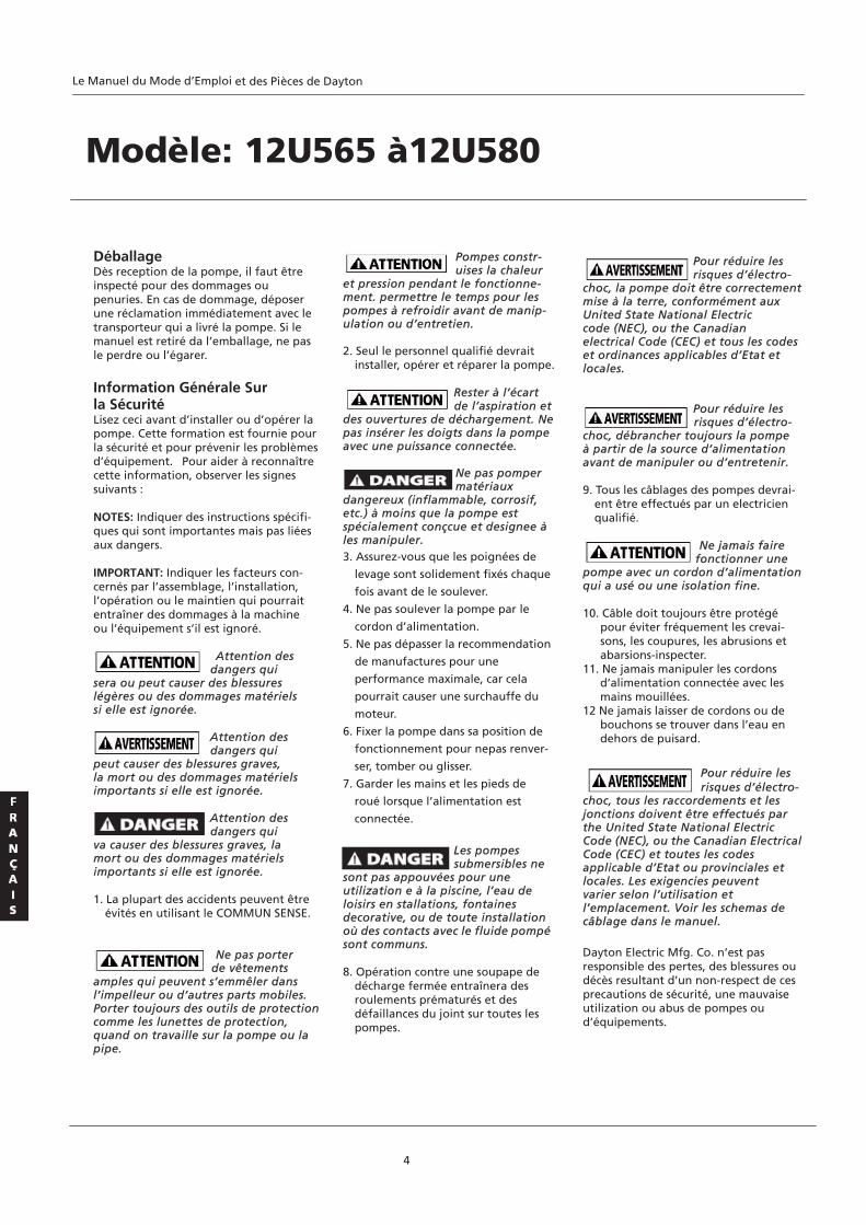
Déballage Dès reception de la pompe, il faut être inspecté pour des dommages ou penuries. En cas de dommage, déposer une réclamation immédiatement avec le transporteur qui a livré la pompe. Si le manuel est retiré da l’emballage, ne pas le perdre ou l’égarer. Information Générale Sur la Sécurité Lisez ceci avant d’installer ou d’opérer la pompe. Cette formation est fournie pour la sécurité et pour prévenir les problèmes d’équipement. Pour aider à reconnaître cette information, observer les signes suivants : NOTES: Indiquer des instructions spécifi- ques qui sont importantes mais pas liées aux dangers. IMPORTANT: Indiquer les facteurs con- cernés par l’assemblage, l’installation, l’opération ou le maintien qui pourrait entraîner des dommages à la machine ou l’équipement s’il est ignoré. Attention des dangers qui sera ou peut causer des blessures légères ou des dommages matériels si elle est ignorée. Attention des dangers qui peut causer des blessures graves, la mort ou des dommages matériels importants si elle est ignorée. Attention des dangers qui va causer des blessures graves, la mort ou des dommages matériels importants si elle est ignorée. 1. La plupart des accidents peuvent être
évités en utilisant le COMMUN SENSE. Ne pas porter
de vêtements amples qui peuvent s’emmêler dans l’impelleur ou d’autres parts mobiles. Porter toujours des outils de protection comme les lunettes de protection, quand on travaille sur la pompe ou la pipe.
Pompes constr- uises la chaleur
et pression pendant le fonctionne- ment. permettre le temps pour les pompes à refroidir avant de manip- ulation ou d’entretien. 2. Seul le personnel qualifié devrait
installer, opérer et réparer la pompe. Rester à l’écart de l’aspiration et des ouvertures de déchargement. Ne pas insérer les doigts dans la pompeavec une puissance connectée.
Ne pas pomper matériaux
dangereux (inflammable, corrosif, etc.) à moins que la pompe est spécialement conçcue et designee à les manipuler. 3. Assurez-vous que les poignées de
levage sont solidement fixés chaque
fois avant de le soulever.
4. Ne pas soulever la pompe par le
cordon d’alimentation.
5. Ne pas dépasser la recommendation
de manufactures pour une
performance maximale, car cela
pourrait causer une surchauffe du
moteur.
6. Fixer la pompe dans sa position de
fonctionnement pour nepas renver-
ser, tomber ou glisser.
7. Garder les mains et les pieds de
roué lorsque l’alimentation est
connectée.
Les pompes submersibles ne sont pas appouvées pour une utilization e à la piscine, l’eau de loisirs en stallations, fontaines decorative, ou de toute installation où des contacts avec le fluide pompésont communs. 8. Opération contre une soupape de
décharge fermée entraînera des roulements prématurés et des défaillances du joint sur toutes les pompes.
Pour réduire les
risques d’électro- choc, la pompe doit être correctementmise à la terre, conformément aux United State National Electric code (NEC), ou the Canadian electrical Code (CEC) et tous les codes et ordinances applicables d’Etat et locales.
Pour réduire les risques d’électro-
choc, débrancher toujours la pompe à partir de la source d’alimentation avant de manipuler ou d’entretenir. 9. Tous les câblages des pompes devrai-
ent être effectués par un electricien qualifié.
Ne jamais faire
fonctionner une pompe avec un cordon d’alimentationqui a usé ou une isolation fine. 10. Câble doit toujours être protégé
pour éviter fréquement les crevai- sons, les coupures, les abrusions et abarsions-inspecter.
11. Ne jamais manipuler les cordons d’alimentation connectée avec les mains mouillées.
12 Ne jamais laisser de cordons ou de bouchons se trouver dans l’eau en dehors de puisard.
Pour réduire les risques d’électro-
choc, tous les raccordements et les jonctions doivent être effectués par the United State National Electric Code (NEC), ou the Canadian Electrical Code (CEC) et toutes les codes applicable d’Etat ou provinciales et locales. Les exigencies peuvent varier selon l’utilisation et l’emplacement. Voir les schemas de câblage dans le manuel. Dayton Electric Mfg. Co. n’est pas responsible des pertes, des blessures ou décès resultant d’un non-respect de ces precautions de sécurité, une mauvaise utilization ou abus de pompes ou d’équipements.
4
Modèle: 12U565 à12U580
Le Manuel du Mode d’Emploi et des Pièces de Dayton

Information Générale Sur la Sécurité (Suite) 13. Ces pompes sont offertes dans une
configuration de câblage de trrois
phases et d’une phase unique. Les
voltages vont varier en fonction de
l’application et peuvent être vus dans
les tableaux de ce manuel.
14. Tous ces modèles de pompe doivent
être utilisés avec un panneau de
contrôle. Moteur: Chaque moteur est fourni avec les thermostats de capteur thermique fixés directement aux enroulements du moteur. Les thermostats ouverts si les enroulements du moteur voient la chal- eur excessive et, par ordre, on ouvre l’entrepreneur à moteur dans le pann- eau de contrôle, brise l’alimentation de la pompe. Lorsque le moteur est arrêté en raison d’un état de surchauffe, il n’ira pas démarrer jusque le moteur ait refroidi. Attention de défaillance du joint du moteur: la chambre de joint est remplie d’huile et doté de sondes d’humidité pour détecter fuites d’eau grâce au joint d’étanchéité inférieur. Les sondes peu- vent également détecter l’humidité présente dans le moteur supérieur de logement. La présence d’eau alimente une rouge lumière d’avertissement de fuite sur le panneau de contrôle. Ceci est seule- ment un voyant d’avertissement, et n’arrête pas le moteur. Il indique que une fuite s’est produite et que la pompe doit être réparée. Normalement, cela indique que le joint hors-bord a coulé. Permettre à l’unité de fonctionner troo longtems après l’avertissement pourrait provoquer une fuite du joint supérieur avec une défaite du moteur. La résis- tance à travers les sondes d’humidité (défaite du joint) doit être vérifiée après qu’une lumière d’avertissement a allumé. Cela peut être fait en débran- chant les fils de commande rouge et oranged de la commande
panneau, et mesurer la résistance avec un ohmmètre entre les câbles. Le relevé doit être 100 000 ohms ou plus grand. Si les valeurs mesurées sont inférieures à celles indiquées ci-dessus, puis la pompe peut avoir une panne de joint inférieur et nécessiter des services. Note: Défaut d’utiliser des circuits app- ropriés et de connecter la protection de surchauffe du moteur dans le panneau de contrôle reviendrait à nier toutes les garanties. Cordon d’alimentation du moteur, cordon de contrôle et cap de cordon Assemblé: Chaque cordon d’alimen- tation du moteur a 4 conducteurs: blanc, noir, rouge et vert. Pour le moteur triphasé, les conduteurs rouge, noir et blanc se connecter à la ligne de trois fils, et le vert est relié à une bonne masse. Interchanger chaque deux lignes seront inversés la rotation du moteur. Pour la phase unique, les fils blanc et noir se connecter aux bornes de deux lignes et le rouge se connecte au terminal d’enroulement de départ. Le vert est à la masse et doit être raccordé à une terre à l’extérieur (voir Figure 4 à la page 9). Note: La rotation doit être dans le sens horaire lorsqu’on les observe du haut de la pompe. Ceci peut être vérifié en notant la direction du couple de la pompe est basée sur la direction initiale. Une pompe proprement rotative sera laquelle dont le couple dans le sens antihoraire lors du démarrage. Le cable de contrôle a 5 conducteurs: noir, blanc, rouge, jaune et vert. Les blanc et noir se connectent aux terminaux du capteur thermique ; les rouge et jaune se connectent aux terminaux défauts du joint ; et le vert se connecte à la masse dans le panneau de contrôlel (voir Figure 4 à la page 9).
Le cap du cordon est époxy en pot. Le cap du cordon offre une connection de câble étanche. Cela permet le cap du cordon, avec des cordes, d’être retiré du moteur. Avec cet arrangement, les cordes peuvent être installées en perm- anence sans un raccord étanche dans le puisard. Les câbles de contrôle et d’ali- mentation ne peuvent pas être épissés! Lorsque la pompe est retirée du service, le cap du cordon peut rester et être réinstallé lorsque la pompe est retournée. Note: Chaque cable a un fils vert à la masse et doit être correctement mis à la terre selon le Code national d’électricité et les codes locales. Contrôles de moteur électrique: Toutes les commandes électriques et les équip- ements avec démarrage du moteur doiv-ent être tels que spécifiés dans les instructions. Pré-opération VERIFIER LE VOLTAGE ET LA PHASE Avant d’opérer la pompe, verifier pour s’assurer que les informations du vol- tage et da la phase estampillés sur la plaque d’idendification de la pompe corespondent à l’alimentation disponible. VERIFIER LA ROTATION DE POMPE Avant de mettre la pompe en service pour la première fois, la rotation du moteur doit être vérifiée. Rotation du moteur incorrecte peut entraîner des performances de la pompe pauvres et peut endommager le moteur et /ou la pompe. PLAQUE D’IDENTIFICATION Noter les numerous sur la plaque d’identification de la pompe et les enregistrer à la fin de ce manuel pour une reference future.
5
Dayton® Pompes à Boue
Condensateurs & Relais sur le Panneau de contrôle
Modèle Démarrage de condensateur
Fonction de condensateur
NOTE: Les condensateurs & relais couvertes dans le panneau de contrôle, ils ne sont pas fournis avec la pompe.
Universal Motor relais de départ potentielTension continue Min Coil Pick-up Max Drop Out Max
2HP 230V 1PH 161-193uf - 220VAC 15uf – 370VAC 350V 200V 75V
3HP 230V 1PH 430-516uf – 220VAC 30uf – 370VAC 350V 200V 75V
5HP 230V 1PH 270-324uf – 220VAC 25uf – 370VAC 400V 200V 80V
7.5HP 230V 1PH 750 uf – 220VAC 40 uf – 370VAC 400V 200V 80V
R
Le Manuel du Mode d’Emploi Modèle 12U565 à 12U580et des Pièces de Dayton
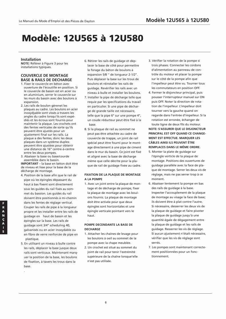
Installation NOTE: Référer à Figure 3 pour les installations typiques. COUVERCLE DE MONTAGE BASE & RAILS DE DECHARGE 1. Fixer le couvercle en béton avec
ouverture de l’écoutille en position. Si le couvercle de bassin est en acier ou en aluminium, serrer le couvercle sur les murs du bassin avec des boulons à expansion.
2. Les rails de boulon gèrenet les plaques au cadre. Les boulons en acier inoxydyable sont vissés à travers les angles du cadre lorsqu’ils sont expé- diés et les écrous sont fournis pour maintenir la plaque. Les crochets ont des fentes verticales de sorte qu’ils peuvent être ajustés pour un ajustement final sur les rails. La plaque a des fentes, donc les deux plaques dans un système duplex peuvent être ajustées pour obtenir une distance de 16’’ centre-à-centre entre les deux pompes.
3. Abaisser la base ou base/courde assemblée dans le bassin.
IMPORTANT – la base en béton doit être de niveau et lisse pour la base de la décharge de montage. 4. Position de la base afin que le rail de
pipe où les épingles dépassant du
haut à bas fixent sont directement
sous les guides du rail fixés au som-
met du bassion. Les guides du rail
doivent être positionnés à mi-chemin
dans les fentes de réglage vertical.
Couper les rails de pipe à la longueur
propre et les installer entre les rails de
guidage en haut de bassin et les
épingles sur la base. Les rails de
guidage sont 3/4’’ scheduling 40,
galvanisés ou en acier inoxydable ou
en fibre de verre renforcée de pipe en
plastique.
5. En utilisant un niveau à bulle contre
les rails, déplacer la base jusque deux
rails sont verticaux. Maintenant marq-
uer la position de la base, les boulons
de fixation, à tavers les trous dans la
base.
.
6. Rétirer les rails de guidage et dép-
lacer la base de côté pour permettre
le forage du béton de boulons à
expansion 5/8 ‘’ de longueur 2-1/2’’.
Puis déplacer la base sur les trous de
boulons et réinstaller les rails de
guidage. Revérifier les rails avec un
niveau à bulle et installer les boulons.
7. Installer la pipe de décharge telle que
requie par les specifications du travail
en particulier. Si une pipe de déchar-
ge de grande taille est nécessaire,
telle que la pipe 6’’ sur une pompe 4’’,
un coude réducteur peut être fixé à la
base.
8. Si la plaque de rail au sommet ne
peut pas être attachée au cadre de
couvercle de trappe, un joint de rail
spécial peut être fourni pour le mont-
age directement à une pipe de ciment
dans le mur du bassin. Ce joint est fixé
et aligné avec la base de décharge
même que celle décrite pour la pla-
que de rail de guidage fixée au cadre.
FIXATION DE LA PLAQUE DE MONTAGE
A LA POMPE
1. Avec un joint entre la plaque de mon-
tage et de décharge de pompe, fixer
la plaque de montage avec les boul-
ons fournis. La plaque de montage
doit être activée pour que deux
épingles sont horizontales et une
épingle verticale pointant vers le
haut.
.
POMPE DECENDANTE LA BASE DE
DECHARGE
1. Attacher les chaînes de levage pour
les boulons à oeil au sommet de la
pompe avec la chape meublée.
2. Un crochet est situé au sommet du
joint de rail pour tenir l’extrémité
supérieure de la chaîne lorsque’elle
n’est pas utilisée.
3. Vérifier la rotation de la pompe si
trois phases. Connecter les cordons
d’alimentation au panneau de con-
trôle du moteur et placer la pompe
sur le côté de la pompe afin que
l’impelleur peut être vu. Tourner tous
les commutateurs en position OFF.
4. Fermer le disjoncteur principal, puis
pousser l’interrupteur manuel sur ON
puis OFF. Noter la direction de rota-
tion de l’impelleur. L’impelleur doit
tourner vers la gauche quand on
regarde dans l’entrée d’impelleur. Si la
rotation est erronée, échanger de
toute ligne de deux fils du moteur.
NOTE: S’ASSURER QUE LE DISJONCTEUR
PRINCIPAL EST OFF QUAND CE CHANGE-
MENT EST EFFECTUE. MARQUER LES
CÂBLES AINSI ILS PEUVENT ÊTRE
REMPLACES DANS LE MÊME ORDRE.
5. Monter la plate de guidage sur
l’épingle verticle de la plaque de
montage. Positions des ouvertures de
guidage parallèle avec la face de pla-
que de montage. Serrer les deux vis de
réglage, mais ne pas serrer trop à ce
moment.
6. Abaisser lentement la pompe en bas
des rails de guidage à la base.
Inspecter l’accouplement de la plaque
de montage au visage la face de base;
ils doivent être à plat contre l’autre.
Si nécessaire, desserrer les deux vis de
la plaque de guidage et faire pivoter
la plaque de guidage jusqu’à une
quantité égale de dégagement entre
la plaque de guidage et les rails de
guidage. Resserrer les vis de réglage.
Si aucun ajustement n’était nécessaire,
vérifier que les vis de réglage sont
serrés.
7. Les pompes sont maintenant correcte-
ment positionnées pour un fonc-
tionnement.
6
Modèle: 12U565 à 12U580
Le Manuel du Mode d’Emploi Modèle 12U565 à 12U580et des Pièces de Dayton
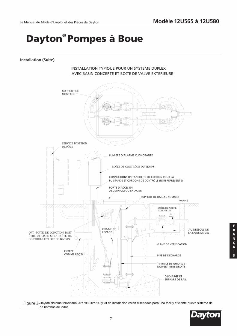
3/8
INSTALLATION TYPIQUE POUR UN SYSTEME DUPLEXAVEC BASIN CONCERTE ET BO?TE DE VALVE EXTERIEURE
SUPPORT DEMONTAGE
SERVICE D'OPTIONDE P? LE
LUMIERE D'ALARME CLIGNOTANTE
BO?TE DE CONTR? LE DU TEMPS
CONNECTIONS D'ETANCHEITE DE CORDON POUR LAPUISSANCE ET CORDONS DE CONTR LE (NON REPRESENTE)
BO?TE DE VALVEEXTERIEUR
VANNE
PORTE D'ACCES ENALUMINIUM OU EN ACIER
OPT. BO?TE DE JONCTIONDOIT êTRE UTILISEE SI LABO?TE DE CONTR? LE ESTOFF DE BASSIN
ENTREECOMME REQ'D
SUPPORT DE RAIL AU SOMMET
AU-DESSOUS DELA LIGNE DE GEL
VLAVE DE VERIFICATION
PIPE DE DECHARGE
34" RAILS DE GUIDAGE-
DOIVENT êTRE DROITS
DéCHARGE ETSUPPORT DE RAIL
CHA?NE DELEVAGE
7
Installation (Suite)
Figure 3-
Dayton® Pompes à Boue
SERVICE D’OPTION DE PÔLE
BOÎTE DE CONTRÔLE DU TEMPS
BOÎTE DE VALVE EXTERIEUR
OPT. BOÎTE DE JONCTION DOIT ÊTRE UTILISEE SI LA BOÎTE DE CONTRÔLE EST OFF DE BASSIN
R
Le Manuel du Mode d’Emploi Modèle 12U565 à 12U580et des Pièces de Dayton
Dayton sistema ferroviario 20Y788 20Y790 y kit de instalación están disenados para una fácil y eficiente nuevo sistema dede bombas de lodos.
Ô
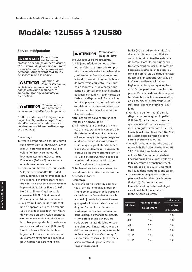
Service et Réparation
L’alimentation électrique du
moteur de la pompe doit être débran- ché et verrouillé pour empêcher toute risque électrique dangereuse ou du personnel danger avant tout travail de service faite à la pompe.
Opérations de Pompes s’accumule
la chaleur et la pression; laisser la pompe refoirdir à température ambiante avant de manipuler ou d’entretien.
Toujours porter une protection
oculaire en travaillant sur les pompes. NOTE: Reportez-vous à la Figure 7 à la page 14 ou Figure 8 à la page 18 pour identifier les numerous de reference pendant les procédures de démontage et de montage.
Demontage
1. Avec la pompe située dans un endroit
sûr, enlever les vis (Réf.No.12) fixant la
plaque d’étanchéité (Réf.No.8) à la
volute (Réf.No.1). Le moteur de
logement assemblé (Réf.No.18) et
l’impelleur (Réf.No.5) peuvent être
enlevés comme une unité.
2. Laisser cet unite vers le bas sur le côté.
Si le joint inférieur (Réf.No.7) doit
être supprimé, il est recommandé que
l’huile dans la chambre étanche soit
drainée. Cela peut être fait en retirant
le plug (Réf.No.23 sur figure 7, Réf.
No. 21 sur figure 8) qui est sur le
couvercle (Réf.No.11) et drainant
l’huile dans un récipient contenant.
3. Pour retirer l’impelleur: en utilisant
une clé appropriée, la vis de retenue
et la rondelle d’impelleur (Réf. No. 4)
doivent être enlevés. Cela peut néces-
siter un morceau de bois placé entre
les aubes pour garder la roue de tour-
ner tout en retirant la vis (Réf. No.4).
Une fois la vis a été enlevée, taper
légèrement avec un marteau autour
du diamètre extérieur de l’impelleur
pour deserrer de l’arbre et la clé.
L’impelleur est
large et lourd
et auta besoin d’être supporté.
4. Si le joint inférieur doit être retiré,
retirer d’abord le ressort de compre-
ssion qui monte entre l’impelleur et le
joint assemblé. Prendre ensuite une
paire de tournevis et enlever la bague
de compression qui entoure le souff-
let en caoutchouc sur la partie tour-
nante du joint assemblé. En utilisant à
nouveau les tounevis, lever le reste de
l’arbre. Le siège céramic fix peut être
retiré en plaçant un tournevis entre le
caoutchouc et la face céramique puis
enlevant, en travaillant aoutour du
diamètre entier.
Note: Ces pieces doivent être jetés et
installer un nouveau joint.
5. Si l’huile dans la chamber étanche a
été drainée, examiner le contenu afin
de determiner si le joint supérieur a
été endommagé. Les signes de gravier
ou d’autre matérial abrasif peuvent
indiquer que le joint étanche supér-
ieur a été en dommagé. Pressuriser le
moteur de logement assemblé entre 7
et 10 psis et observer toute baisse de
pression indiquent si le joint supér-
ieur fonctionne correctement.
Note: Les reparations étanches supér-
ieurs doivent être faites dans un centre
de service autorisé.
Remontage
1. Retirer la partie céramique du nou-
veau joint de l’emballage. Brosser
l’huile isolante autour de la partie en
caoutchouc de l’assemblé et dans la
poche du joint de logement. Remar-
que, garder l’huile écartée da la face
du joint. Sans enlevant la face du
joint, appuyer le siège fixe céramic
dans la plaque d’étanchéité (Ref.No.
8). Une pièce de pipe en PVC qui
s’adapte sur la face du joint fonctio-
nne bien pour l’installation. Avec un
chiffon propre, essuyer légèrement la
surface du joint pour s’assurer qui’il
est poussière et sans huile. Retirer la
partie rotative du joint de l’emba-
llage et légèrement
huiler (Ne pas utiliser de graisse) le
diamètre intérieur du soufflet en
caoutchouc et le diamètre extérieur
de l’arbre. Placer le joint sur l’arbre.
Uniformément presser sur le corps de
l’assemblé rotational et le glisser au
fond de l’arbre jusqu’à ce que les faces
du joint se rencontrent. Un tuyau en
PVC avec un diamètre intérieur
légèrement plus grand que le diam-
ètre d’arbre peut bien travailler pour
presser l’assemblé de rotation en posi-
tion. Une fois que le joint assemblé est
en place, placer le ressort sur le regi-
stre dans la portion rotationale du
joint.
2. Position la clé (Réf. No. 6) dans le
siège de l’arbre. Aligner l’impelleur
(Réf. No.5) sur l’arb re, en s’assurant
que le ressort de joint est correcte-
ment enregistré sur la face arrière de
l’impelleur. Insérer la vis (Réf. No. 4) et
de l’assemblage de rondelle dans
l’arbre et serrer à 93 ft.-lbs.
3. Remplir la chamber étanche avec de
nouvelle huile isolée (#10 huile ou US
SAE 10 huile). Une fente d’air de
volume 10-15% doit être laissée à
l’expansion de l’huile quand elle est à
la température de fonctionnement.
Voir tableau ci-dessous : le montant
de l’huile dont les pompes ont besoin.
4. Le moteur et l’impelleur assemble
peuvent être installés dans la volute
(Ref.No.1). Assurez-vous que
l’impelleur est correctement aligné
avec la volute. Installer les vis
(Ref.No.12) et les serrer.
8
Modèle: 12U565 à 12U580
ModèleHuile de moteur
de logement
Huile dans
chamber
d’éanchéite 2HP 1.7L 0.8L
3HP 1.4L 0.8L
5HP 2.3L 1.6L
7.5HP 2.2L 1.6L
10HP 2.5L 1.8L
15HP 2.4L 1.8L
Le Manuel du Mode d’Emploi et des Pièces de Dayton
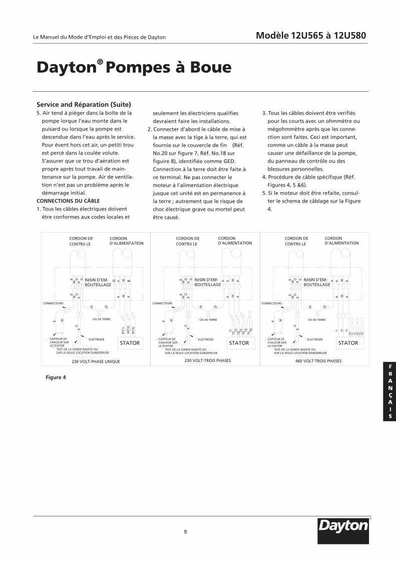
Service and Réparation (Suite) 5. Air tend à piéger dans la boîte de la
pompe lorque l’eau monte dans le
puisard ou lorsque la pompe est
descendue dans l’eau après le service.
Pour évent hors cet air, un petiti trou
est percé dans la coulée volute.
S’assurer que ce trou d’aération est
propre après tout travail de main-
tenance sur la pompe. Air de ventila-
tion n’est pas un problème après le
démarrage initial.
CONNECTIONS DU CÄBLE
1. Tous les câbles électriques doivent
être conformes aux codes locales et
seulement les électriciens qualifies
devraient faire les installations.
2. Connecter d’abord le câble de mise à
la masse avec la tige à la terre, qui est
fournie sur le couvercle de fin (Réf.
No.20 sur figure 7, Réf. No.18 sur
figuire 8), identifiée comme GED.
Connection à la terre doit être faite à
ce terminal. Ne pas connecter le
moteur à l’alimentation électrique
jusque cet unité est en permanence à
la terre ; autrement que le risque de
choc électrique grave ou mortel peut
être causé.
3. Tous les câbles doivent être verifiés
pour les courts avec un ohmmètre ou
mégohmmètre après que les conne-
ction sont faites. Ceci est important,
comme un câble à la masse peut
causer une défaillance de la pompe,
du panneau de contrôle ou des
blessures personnelles.
4. Procédure de câble spécifique (Réf.
Figures 4, 5 &6).
5. Si le moteur doit être refaite, consul-
ter le schema de câblage sur la Figure
4.
9
Figure 4
Dayton® Pompes à Boue
STATOR
CORDOND'ALIMENTATION
CORDON DECONTRô LE
RéSIN D'EM-BOUTEILLAGE
BW
OR
B W
OR
VIS DE TERRE
R W B
R(T
1)
W(T
2)
B(T
3)
GG
CAPTEUR DECHALEUR SURLE STATOR
ELECTRODE
TEST DE LA SONDE RéSISTE OUSUR LA SEULE LOCATION DANGEREUSE
230 VOLT-PHASE UNIQUE
CONNECTEURS
STATOR
BW
OR
B W
OR
R W B
GG
ELECTRODE
230 VOLT-TROIS PHASES
T1T7
T2T8
T3T9
T4T5
T6
STATOR
BW
OR
B W
OR
R W B
GG
ELECTRODE
460 VOLT-TROIS PHASES
T1
T4
T2 T3
T7 T5 T8 T6 T9
BW
OR R W BGG BW
OR
G BW
OR
GR W BG R W BG
CORDON DECONTRô LE
CORDON DECONTRô LE
CORDOND'ALIMENTATION
CORDOND'ALIMENTATION
RéSIN D'EM-BOUTEILLAGE
RéSIN D'EM-BOUTEILLAGE
VIS DE TERRE VIS DE TERRE
CONNECTEURS CONNECTEURS
CAPTEUR DECHALEUR SURLE STATOR
TEST DE LA SONDE RéSISTE OUSUR LA SEULE LOCATION DANGEREUSE
CAPTEUR DECHALEUR SURLE STATOR
TEST DE LA SONDE RéSISTE OUSUR LA SEULE LOCATION DANGEREUSE
R
Le Manuel du Mode d’Emploi Modèle 12U565 à 12U580et des Pièces de Dayton
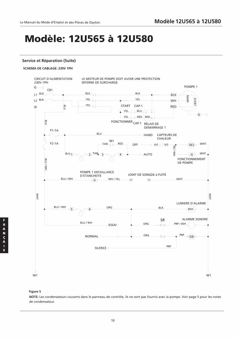
10
SCHEMA DE CABLAGE: 230V 1PH
Service et Réparation (Suite)
Figure 5
Modèle: 12U565 à 12U580
NOTE: Les condensateurs couverts dans le panneau de contrôle, ils ne sont pas fournis avec la pompe. Voir page 5 pour les notes
de condensateur.
L1
L2
CB1
1 5
2
BLK
WH
RED
G
G
N
1 2 3 4
H1 H1
G
M1
R S1 S1
5 6 RED
SR
4 2
4 3 1 5
CIRCUIT D'ALIMENTATION230V-1PH
BLK
BLK
BLK
YEL
YEL
M1
BLK
YEL
POMPE 1
MA
IN
STAR
TBLU START CAP.1
FONCTIONNER CAP.1 RELAIS DEDEMARRAGE 1
YEL
YEL
BLU
RED RED
BLU
F1-1A
F2-1A
BLU
BLU
TAN
TAN RED
HAND CAPTEURS DECHALEUR
OFF
AUTO
BLU
/ WH
RD
/ WH
WHT
WHT
FONCTIONNEMENTDE POMPE
BLU / WH
POMPE 1 DEFAILLANCED'ETANCHEITE
WH / YEL
JOINT DE SONGDE à FUITEWHT
WH
T
BLU / WH
BLU / WH
ORG
ESSAI
NORMAL
SILENCE
ORG
ORG
BLK
SR
LUMIERE D'ALARME
ALARME SONOREPRP / WH
PRP
PRP
W1 W1
LE MOTEUR DE POMPE DOIT AVOIR UNE PROTECTIONINTERNE DE SURCHARGE
WH
T
Le Manuel du Mode d’Emploi Modèle 12U565 à 12U580et des Pièces de Dayton
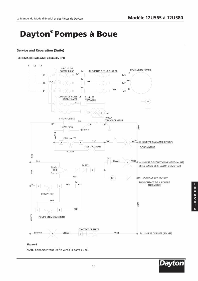
SCHEMA DE CABLAGE: 230&460V 3PH
11
NOTE: Connecter tous les fils vert à la barre au sol.
Figure 6
Service and Réparation (Suite)
Dayton® Pompes à Boue
B
W
RM1
M2
M3
M1
M1
M1 ELEMENTS DE SURCHARGEMOTEUR DE POMPE
L1
L2
L3
L2L1 L3
H1 H3 H2 H4
9 10
FAL
1 2
Y
65
7 8
R 3 4
CIRCUIT DEPOMPE BRISE
CIRCUIT DE CONT? LEBRISE-15 AMP
FUSIBLESPRIMAIRES
1 AMP FUSIBLE
1 AMP FUSEXF
100VATRANSFORMEUR
X1 X2
EAU HAUTE
TEST D'ALARME
AL-LUMIERE D'ALARME(ROUGE)
F-CLIGNOTEUR
Y-LUMIERE DE FONCTIONNEMENT (JAUNE)
M.H.S-SENSIN DE CHALEUR DE MOTEUR
M1- CONTACT SUR MOTEUR
TOC-CONTACT DE SURCHARETHERMIQUE
R- LUMIERE DE FUITE (ROUGE)
M1
MAINOFF
AUTO
M.H.S.
M1
M1
POMPE OFF
POMPE EN MOUVEMENT
CONTACT DE FUITE
BLU
BLU/WH
BLU
BLU
BLU
BLU
/WH
BLU/WH YEL/WH WHT
WH
TW
HT
WHTBLKORGB
LU/W
H
BLU
BLU/WH
WHTRD/WH
RED
REDBRN
BRN
RED
BLK
BLK
BLK
BLK
BLK
G
R
Le Manuel du Mode d’Emploi Modèle 12U565 à 12U580et des Pièces de Dayton
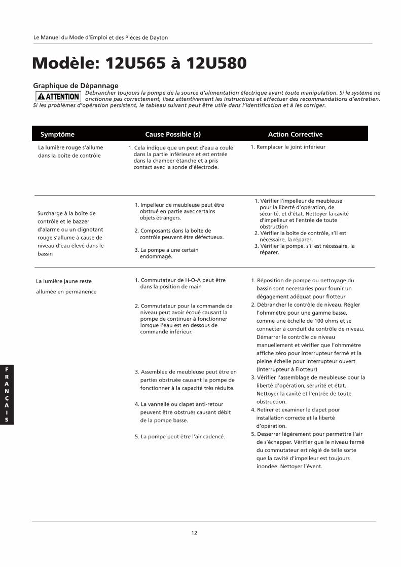
La lumière jaune reste
allumée en permanence
1. Commutateur de H-O-A peut être dans la position de main
2. Commutateur pour la commande de
niveau peut avoir écoué causant la pompe de continuer à fonctionner lorsque l’eau est en dessous de commande inférieur.
3. Assemblée de meubleuse peut être en
parties obstruée causant la pompe de
fonctionner à la capacité très réduite.
4. La vannelle ou clapet anti-retour
peuvent être obstrués causant débit
de la pompe basse.
5. La pompe peut être l’air cadencé.
La lumière rouge s’allume
dans la boîte de contrôle 1. Cela indique que un peut d’eau a coulé
dans la partie inférieure et est entrée dans la chamber étanche et a pris contact avec la sonde d’électrode.
1. Remplacer le joint inférieur
1. Réposition de pompe ou nettoyage du
bassin sont necessaries pour founir un
dégagement adéquat pour flotteur
2. Débrancher le contrôle de niveau. Régler
l’ohmmètre pour une gamme basse,
comme une échelle de 100 ohms et se
connecter à conduit de contrôle de niveau.
Démarrer le contrôle de niveau
manuellement et vérifier que l’ohmmètre
affiche zéro pour interrupteur fermé et la
pleine échelle pour interrupteur ouvert
(Interrupteur à Flotteur)
3. Vérifier l’assemblage de meubleuse pour la
liberté d’opération, sérurité et état.
Nettoyer la cavité et l’entrée de toute
obstruction.
4. Retirer et examiner le clapet pour
installation correcte et la liberté
d’opération.
5. Desserrer légèrement pour permettre l’air
de s’échapper. Vérifier que le niveau fermé
du commutateur est réglé de telle sorte
que la cavité d’impelleur est toujours
inondée. Nettoyer l’évent.
Symptôme Cause Possible (s) Action Corrective
12
Modèle: 12U565 à 12U580Graphique de Dépannage
Débrancher toujours la pompe de la source d’alimentation électrique avant toute manipulation. Si le système ne onctionne pas correctement, lisez attentivement les instructions et effectuer des recommandations d’entretien.
Si les problèmes d’opération persistent, le tableau suivant peut être utile dans l’identification et à les corriger.
Surcharge à la boîte de
contrôle et le bazzer
d’alarme ou un clignotant
rouge s’allume à cause de
niveau d’eau élevé dans le
bassin
1. Impelleur de meubleuse peut être obstrué en partie avec certains objets étrangers.
2. Composants dans la boîte de
contrôle peuvent être défectueux. 3. La pompe a une certain
endommagé.
1. Vérifier l’impelleur de meubleuse pour la liberté d’opération, de sécurité, et d’état. Nettoyer la cavité d’impelleur et l’entrée de toute obstruction
2. Vérifier la boîte de contrôle, s’il est nécessaire, la réparer.
3. Vérifier la pompe, s’il est nécessaire, la réparer.
Le Manuel du Mode d’Emploi et des Pièces de Dayton
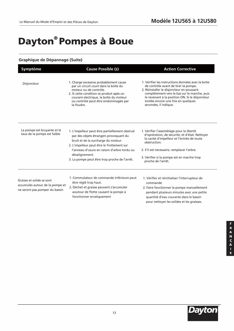
Graphique de Dépannage (Suite)
13
Symptôme Cause Possible (s) Action Corrective
Dayton® Pompes à Boue
Disjoncteur
1. Charge excessive probablement cause
par un circuit court dans la boîte du moteur ou de contrôle.
2. Si cette condition se produit apès un courant electrique, la boîte du moteur ou contrôle peut être endommagée par la foudre.
1. Vérifier les instructions données avec la boîte de contrôle avant de tirer la pompe.
2. Réinstaller le disjoncteur en poussant complètement vers le bas sur le manche, puis le revenant à la position ON. Si le disjoncteur tombe encore une fois en quelques secondes, il indique.
La pompe est bruyante et le taux de la pompe est faible
1. L’impelleur peut être partiellement obstrué
par des objets étrangers provoquant du
bruit et de la surcharge du moteur.
2. L’impelleur peut être le frottement sur
l’anneau d’usure en raison d’arbre tordu ou
désalignement.
3. La pompe peut être trop proche de l’arrêt.
1. Vérifier l’assemblage pour la liberté d’oprération, de sécurité, et d’état. Nettoyer la cavité d’impelleur et l’entrée de toute obstruction.
2. S’il est necessaire, remplacer l’arbre. 3. Vérifier si la pompe est en marche trop
proche de l’arrêt.
Graisse et solide se sont
accumulés autour de la pompe et
ne seront pas pomper du bassin
1. Commutateur de commande inférieure peut
être réglé trop haut.
2. Déchet et graisse peuvent s’accumuler
aoutour de flotte causant la pompe à
fonctionner erratiquement
1. Vérifier et réinitialiser l’interrupteur de
commande
2. Faire fonctionner la pompe manuellement
pendant plusieurs minutes avec une petite
quantité d’eau courante dans le bassin
pour nettoyer les solides et les graisses.
R
Le Manuel du Mode d’Emploi Modèle 12U565 à 12U580et des Pièces de Dayton
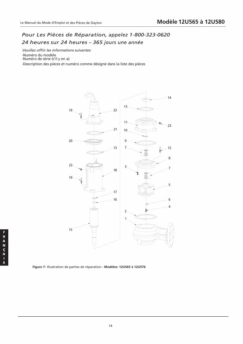
Pour Les Pièces de Réparation, appelez 1-800-323-0620
24 heures sur 24 heures – 365 jours une année
Veuillez offrir les informations suivantes: -Numéro du modèle -Numéro de série (s’il y en a) -Description des pièces et numéro comme désigné dans la liste des pièces
14
Figure 7- Illustration de parties de réparation - Modèles: 12U565 à 12U576
4
6
5
7
8
12
23
14
15
19
23
20
19
1
2
3
7
9
10
11
13
16
17
18
13
21
22
Le Manuel du Mode d’Emploi Modèle 12U565 à 12U580et des Pièces de Dayton
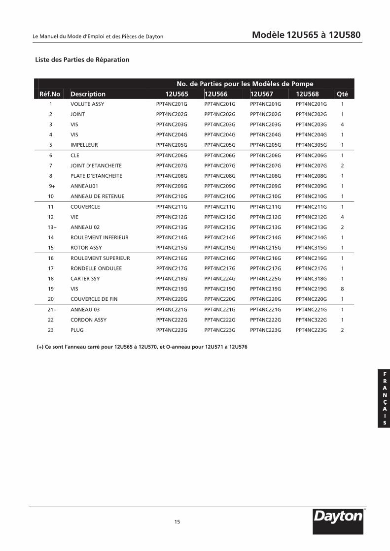
Liste des Parties de Réparation
15
NNo. de Parties pour les Modèles de Pompe
Réf.No. Description 12U565 12U566 12U567 12U568 Qté 1 VOLUTE ASSY PPT4NC201G PPT4NC201G PPT4NC201G PPT4NC201G 1
2 JOINT PPT4NC202G PPT4NC202G PPT4NC202G PPT4NC202G 1
3 VIS PPT4NC203G PPT4NC203G PPT4NC203G PPT4NC203G 4
4 VIS PPT4NC204G PPT4NC204G PPT4NC204G PPT4NC204G 1
5 IMPELLEUR PPT4NC205G PPT4NC205G PPT4NC205G PPT4NC305G 1
6 CLE PPT4NC206G PPT4NC206G PPT4NC206G PPT4NC206G 1
7 JOINT D’ETANCHEITE PPT4NC207G PPT4NC207G PPT4NC207G PPT4NC207G 2
8 PLATE D’ETANCHEITE PPT4NC208G PPT4NC208G PPT4NC208G PPT4NC208G 1
9+ ANNEAU01 PPT4NC209G PPT4NC209G PPT4NC209G PPT4NC209G 1
10 ANNEAU DE RETENUE PPT4NC210G PPT4NC210G PPT4NC210G PPT4NC210G 1
11 COUVERCLE PPT4NC211G PPT4NC211G PPT4NC211G PPT4NC211G 1
12 VIE PPT4NC212G PPT4NC212G PPT4NC212G PPT4NC212G 4
13+ ANNEAU 02 PPT4NC213G PPT4NC213G PPT4NC213G PPT4NC213G 2
14 ROULEMENT INFERIEUR PPT4NC214G PPT4NC214G PPT4NC214G PPT4NC214G 1
15 ROTOR ASSY PPT4NC215G PPT4NC215G PPT4NC215G PPT4NC315G 1
16 ROULEMENT SUPERIEUR PPT4NC216G PPT4NC216G PPT4NC216G PPT4NC216G 1
17 RONDELLE ONDULEE PPT4NC217G PPT4NC217G PPT4NC217G PPT4NC217G 1
18 CARTER SSY PPT4NC218G PPT4NC224G PPT4NC225G PPT4NC318G 1
19 VIS PPT4NC219G PPT4NC219G PPT4NC219G PPT4NC219G 8
20 COUVERCLE DE FIN PPT4NC220G PPT4NC220G PPT4NC220G PPT4NC220G 1
21+ ANNEAU 03 PPT4NC221G PPT4NC221G PPT4NC221G PPT4NC221G 1
22 CORDON ASSY PPT4NC222G PPT4NC222G PPT4NC222G PPT4NC322G 1
23 PLUG PPT4NC223G PPT4NC223G PPT4NC223G PPT4NC223G 2
(+) Ce sont l’anneau carré pour 12U565 à 12U570, et O-anneau pour 12U571 à 12U576
R
Le Manuel du Mode d’Emploi Modèle 12U565 à 12U580et des Pièces de Dayton
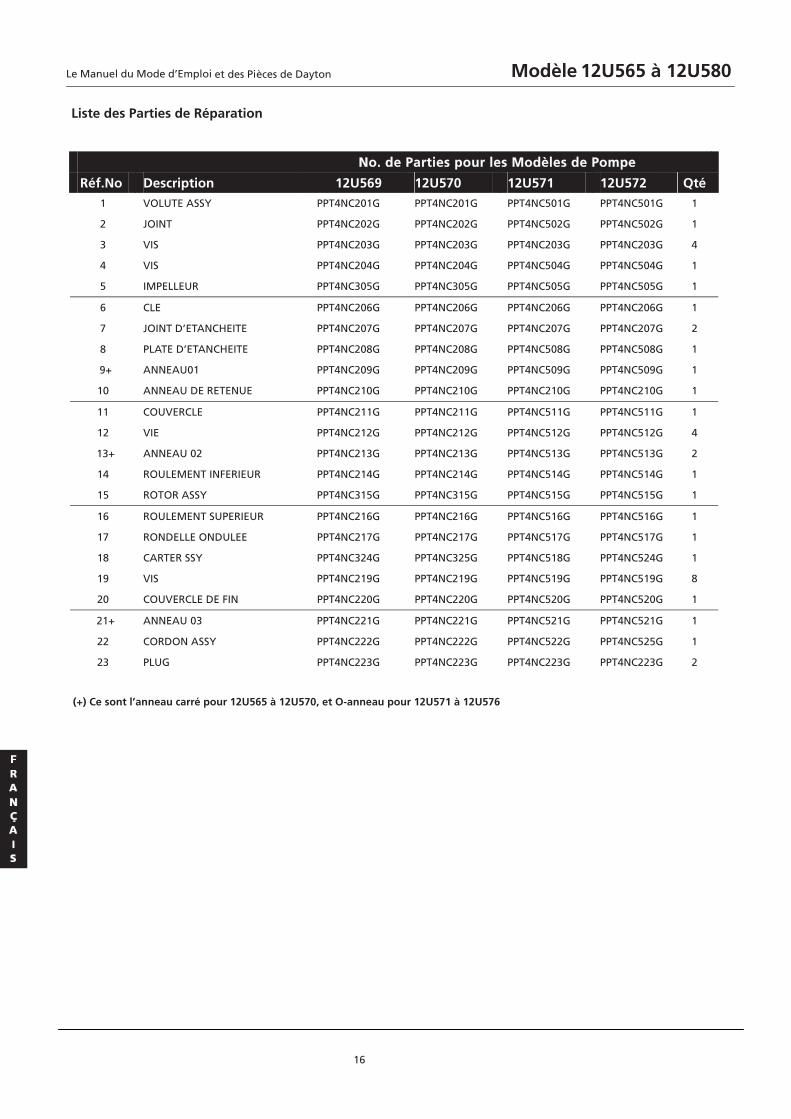
Liste des Parties de Réparation
16
NNo. de Parties pour les Modèles de Pompe
Réf.No. Description 12U569 12U570 12U571 12U572 Qté 1 VOLUTE ASSY PPT4NC201G PPT4NC201G PPT4NC501G PPT4NC501G 1
2 JOINT PPT4NC202G PPT4NC202G PPT4NC502G PPT4NC502G 1
3 VIS PPT4NC203G PPT4NC203G PPT4NC203G PPT4NC203G 4
4 VIS PPT4NC204G PPT4NC204G PPT4NC504G PPT4NC504G 1
5 IMPELLEUR PPT4NC305G PPT4NC305G PPT4NC505G PPT4NC505G 1
6 CLE PPT4NC206G PPT4NC206G PPT4NC206G PPT4NC206G 1
7 JOINT D’ETANCHEITE PPT4NC207G PPT4NC207G PPT4NC207G PPT4NC207G 2
8 PLATE D’ETANCHEITE PPT4NC208G PPT4NC208G PPT4NC508G PPT4NC508G 1
9+ ANNEAU01 PPT4NC209G PPT4NC209G PPT4NC509G PPT4NC509G 1
10 ANNEAU DE RETENUE PPT4NC210G PPT4NC210G PPT4NC210G PPT4NC210G 1
11 COUVERCLE PPT4NC211G PPT4NC211G PPT4NC511G PPT4NC511G 1
12 VIE PPT4NC212G PPT4NC212G PPT4NC512G PPT4NC512G 4
13+ ANNEAU 02 PPT4NC213G PPT4NC213G PPT4NC513G PPT4NC513G 2
14 ROULEMENT INFERIEUR PPT4NC214G PPT4NC214G PPT4NC514G PPT4NC514G 1
15 ROTOR ASSY PPT4NC315G PPT4NC315G PPT4NC515G PPT4NC515G 1
16 ROULEMENT SUPERIEUR PPT4NC216G PPT4NC216G PPT4NC516G PPT4NC516G 1
17 RONDELLE ONDULEE PPT4NC217G PPT4NC217G PPT4NC517G PPT4NC517G 1
18 CARTER SSY PPT4NC324G PPT4NC325G PPT4NC518G PPT4NC524G 1
19 VIS PPT4NC219G PPT4NC219G PPT4NC519G PPT4NC519G 8
20 COUVERCLE DE FIN PPT4NC220G PPT4NC220G PPT4NC520G PPT4NC520G 1
21+ ANNEAU 03 PPT4NC221G PPT4NC221G PPT4NC521G PPT4NC521G 1
22 CORDON ASSY PPT4NC222G PPT4NC222G PPT4NC522G PPT4NC525G 1
23 PLUG PPT4NC223G PPT4NC223G PPT4NC223G PPT4NC223G 2
(+) Ce sont l’anneau carré pour 12U565 à 12U570, et O-anneau pour 12U571 à 12U576
Le Manuel du Mode d’Emploi Modèle 12U565 à 12U580et des Pièces de Dayton

Liste des Parties de Réparation
17
NNo. de Parties pour les Modèles de Pompe
Réf.No. Description 12U573 12U574 12U575 12U576 Qté 1 VOLUTE ASSY PPT4NC501G PPT4NC501G PPT4NC501G PPT4NC501G 1
2 JOINT PPT4NC502G PPT4NC502G PPT4NC502G PPT4NC502G 1
3 VIS PPT4NC203G PPT4NC203G PPT4NC203G PPT4NC203G 4
4 VIS PPT4NC504G PPT4NC504G PPT4NC504G PPT4NC504G 1
5 IMPELLEUR PPT4NC505G PPT4NC705G PPT4NC705G PPT4NC705G 1
6 CLE PPT4NC206G PPT4NC206G PPT4NC206G PPT4NC206G 1
7 JOINT D’ETANCHEITE PPT4NC207G PPT4NC207G PPT4NC207G PPT4NC207G 2
8 PLATE D’ETANCHEITE PPT4NC508G PPT4NC508G PPT4NC508G PPT4NC508G 1
9+ ANNEAU01 PPT4NC509G PPT4NC509G PPT4NC509G PPT4NC509G 1
10 ANNEAU DE RETENUE PPT4NC210G PPT4NC210G PPT4NC210G PPT4NC210G 1
11 COUVERCLE PPT4NC511G PPT4NC511G PPT4NC511G PPT4NC511G 1
12 VIE PPT4NC512G PPT4NC512G PPT4NC512G PPT4NC512G 4
13+ ANNEAU 02 PPT4NC513G PPT4NC513G PPT4NC513G PPT4NC513G 2
14 ROULEMENT INFERIEUR PPT4NC514G PPT4NC514G PPT4NC514G PPT4NC514G 1
15 ROTOR ASSY PPT4NC515G PPT4NC715G PPT4NC715G PPT4NC715G 1
16 ROULEMENT SUPERIEUR PPT4NC516G PPT4NC516G PPT4NC516G PPT4NC516G 1
17 RONDELLE ONDULEE PPT4NC517G PPT4NC517G PPT4NC517G PPT4NC517G 1
18 CARTER SSY PPT4NC526G PPT4NC718G PPT4NC724G PPT4NC726G 1
19 VIS PPT4NC519G PPT4NC519G PPT4NC519G PPT4NC519G 8
20 COUVERCLE DE FIN PPT4NC520G PPT4NC520G PPT4NC520G PPT4NC520G 1
21+ ANNEAU 03 PPT4NC521G PPT4NC521G PPT4NC521G PPT4NC521G 1
22 CORDON ASSY PPT4NC527G PPT4NC722G PPT4NC522G PPT4NC525G 1
23 PLUG PPT4NC223G PPT4NC223G PPT4NC223G PPT4NC223G 2
(+) Ce sont l’anneau carré pour 12U565 à 12U570, et O-anneau pour 12U571 à 12U576
R
Le Manuel du Mode d’Emploi Modèle 12U565 à 12U580et des Pièces de Dayton
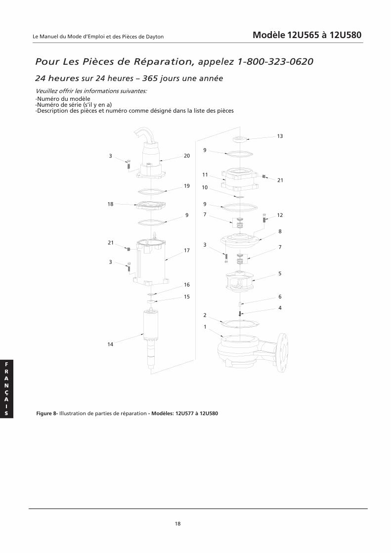
Pour Les Pièces de Réparation, appelez 1-800-323-0620
24 heures sur 24 heures – 365 jours une année
Veuillez offrir les informations suivantes: -Numéro du modèle -Numéro de série (s’il y en a) -Description des pièces et numéro comme désigné dans la liste des pièces
18
Figure 8- Illustration de parties de réparation - Modèles: 12U577 à 12U580
4
6
5
7
8
12
21
13
14
3
21
18
3
1
2
3
7
9
10
11
9
15
16
17
9
19
20
Le Manuel du Mode d’Emploi Modèle 12U565 à 12U580et des Pièces de Dayton

Liste des Parties de Réparation
19
No. de Parties pour les Modèles de Pompe
Réf.No. Description 12U577 12U578 12U579 12U580 Qté
1 VOLUTE A 1 G101CN4TPP G101CN4TPP G101CN4TPP G101CN4TPP YSS
1 G201CN4TPP G201CN4TPP G201CN4TPP G201CN4TPP TNIOJ 2
8 G915CN4TPP G915CN4TPP G915CN4TPP G915CN4TPP SIV 3
1 G405CN4TPP G405CN4TPP G405CN4TPP G405CN4TPP SIV 4
1 G551CN4TPP G551CN4TPP G501CN4TPP G501CN4TPP RUELLEPMI 5
1 G601CN4TPP G601CN4TPP G601CN4TPP G601CN4TPP ELC 6
7 JOINT D’ETANCHEITE PPT4NC107G PPT4NC107G PPT4NC107G PPT4NC107G 2
8 PLATE D’ETANCHEITE PPT4NC108G PPT4NC108G PPT4NC108G PPT4NC108G 1
9 O-ANNEAU 01 PPT4NC109G PPT4NC109G PPT4NC109G PPT4NC109G 3
10 ANNEAU DE RETENUE PPT4NC110G PPT4NC110G PPT4NC110G PPT4NC110G 1
1 G111CN4TPP G111CN4TPP G111CN4TPP G111CN4TPP ELCREVUOC 11
8 G211CN4TPP G211CN4TPP G211CN4TPP G211CN4TPP SIV 21
13 ROULEMENT INFERIEUR PPT4NC113G PPT4NC113G PPT4NC113G PPT4NC113G 1
14 ROTOR A 1 G451CN4TPP G451CN4TPP G411CN4TPP G411CN4TPP YSS
15 ROULEMENT SUPERIEUR PPT4NC115G PPT4NC115G PPT4NC115G PPT4NC115G 1
16 RONDELLE ONDULEE PPT4NC116G PPT4NC116G PPT4NC116G PPT4NC116G 1
17 CA 1 G851CN4TPP G651CN4TPP G421CN4TPP G711CN4TPP YSS RETR
18 COUVERCLE DE FIN PPT4NC118G PPT4NC118G PPT4NC118G PPT4NC118G 1
19 O- ANNEAU 02 PPT4NC119G PPT4NC119G PPT4NC119G PPT4NC119G 1
20 CORDON ASSY PPT4NC120G PPT4NC125G PPT4NC157G PPT4NC120G 1
2 G322CN4TPP G322CN4TPP G322CN4TPP G322CN4TPP GULP 12
R
Le Manuel du Mode d’Emploi Modèle 12U565 à 12U580et des Pièces de Dayton

Cordon d'alimentation
Ecrou
Adapteur
Douille
Unité du cordond'alimentation
Anneau-O
Terminal A
EPOXY
Fil de conduise/cordond'alimentation
Terminal B
Cordon de contr?le
Fil de conduise/cordonde contr? le
Pour Les Pièces de Réparation, appelez 1-800-323-0620
24 heures sur 24 heures – 365 jours une année
Veuillez offrir les informations suivantes: -Numéro du modèle -Numéro de série (s’il y en a) -Description des pièces et numéro comme désigné dans la liste des pièces
20
Figure 9 –Cordon Assemblé d’alimentation
Cordon de contrôle
Fil de conduise/cordon De contrôle
Le Manuel du Mode d’Emploi Modèle 12U565 à 12U580et des Pièces de Dayton
GARANTIE LIMITEE
DAYTON GARANTIE LIMITEE POUR UNE ANNEE. DAYTON POMPES À BOUE, MODELES COUVERTS DANS CE MANUEL, SONT
GARANTIS PAR DAYTON ELECTRIC MFG. CO. (DAYTON) A L’UTILISATEUR INITIAL CONTRE LES DEFAUTS DE LA FABRICATION OU DE
LA MATIERE SOUS L’UTILISATION NORMALE POUR UNE ANNEE DE GARANTIE APRES LE JOUR D’ACHAT. TOUTE PIECE QUI EST
CONSIDEREE COMME DEFECTUEUSE DANS LA MATIERE OU LA FABRICATION ET RETOURNEE A UN CENTRE DE SERVICE AUTORISE,
COMME DAYTON DESIGNE, FRAIS DE PORT PAYE, SERA, COMME LE RECOURS EXCLUSIF, REPARE OU REMPLACE AU CHOIX DE
DAYTON. POUR LA PROCEDURE DE RECLAMATION DE LA GARANTIE LIMITEE, VOIR “DISPOSITION PROMPTE” CI-DESSOUS. CETTE
GARANTIE LIMITEE DONNE AUX ACHETEURS DES DROITS SPECIFIQUES QUI VARIENT SELON LES JURISDICTIONS LIMITATION DE LA RESPONSABILITE. DANS LA MESURE PERMISE PAR LES LOIS APPLICABLES, LA RESPONSABILITE DE DAYTON
POUR LES DOMMAGES DIRECTS ET ACCIDENTELS EST EXPRESSEMENT EXCLUE. LA RESPONSABILITE DE DAYTON DANS TOUS LES CAS
EST LIMITEE ET NE PEUT PAS DEPASSER LE PRIX D’ACHAT PAYE. EXCLUSION DE GARANTIE. UN EFFORT ASSIDU A ETE FAIT POUR FOURNIR PRECISEMENT LES INFORMATIONS ET ILLUSTRATIONS
SUR LES PRODUITS DANS CETTE BROCHURE; TOUTEFOIS, CES INFORMATIONS ET ILLUSTRATIONS SONT POUR LE SEUL BUT DE
L’IDENDIFICATION, ET N’EXPRIME OU N’IMPLIQUE PAS UNE GARANTIE QUE LES PRODUITS SONT COMMERCIALISABLES, OU
S’ADAPTENT A UN USAGE PARTICULIER, OU QUE LES PRODUITS SERONT NECESSAIREMENT CONFORMES AUX ILLUSTRATIONS OU
DESCRIPTIONS. SAUF CE QUE FOURNI CI-APRES, AUCUNE GARANTIE OU AFFIRMATION DE FAIT, EXPRESSEE OU IMPLIQUEE, AUTRE
QUE CELLE ENONCEE A LA GARANTIE LIMITEE CI-DESSUS N’EST FAITE OU AUTORISEE PAR DAYTON.
Conseils et recommendations techniques, Désistement. Nonobstant toute pratique ou transaction ou les
usages commerciaux, la vente ne comprend pas la fourniture des conseils techniques, assistances techniques ou de la conception
du système. Dayton n’assume aucune obligation ou responsabilité en raison de toutes les recommendations, des avis ou des
conseils non autorisés quant au choix, à l’installation ou l’utilisation des produits. Adaptabilité du Produit. De nombreuses juridictions ont des codes et règlements régissant les ventes, la construction,
l'installation et / ou l'utilisation de produits pour certains usages, qui peuvent différencier de ceux des régions voisines. Bien que
des tentatives soient faites pour assurer la conformité des produits de Dayton à ces codes, Dayton ne peut pas garantir la
conformité, et ne peut pas être responsable de la façon dont le produit est installé ou utilisé. Avant l'achat et l'utilisation d'un
produit, Examinez les applications de produits, et tous les codes et règlements nationaux et locaux applicables, et assurez-vous que
le produit, l'installation et l'utilisation soient en accord avec eux.
Certains aspects de désistement ne sont pas applicables aux produits de consommation; e.g., (a) Certaines juridictions ne
permettent pas l'exclusion ou la limitation des dommages fortuits ou consécutifs, donc la limitation ou l'exclusion susmentionnée
ne s'applique pas à vous; (b) aussi, certaines juridictions ne permettent pas la limitation sur la durée d'une garantie implicite, En
conséquence, la limitation ci-dessus ne s'applique peut-être pas à vous; et (c) par la lois, durant la période de cette garantie limitée,
toutes les garanties implicites de commercialisation implicite ou toute adéquation à un usage particulier applicable aux produits de
consommation achetés par les consommateurs, ne peuvent être exclues ni déniées.
Disposition Prompte. Un effort de bonne foi sera fait pour corriger ou ajuster rapidement à l'égard de tout produit
qui s'avère défectueux sous garantie limitée. Pour tout produit considéré défectueux sous garantie limitée, d'abord écrire
ou appeler le revendeur auprès duquel le produit a été acheté. Le revendeur donnera des directives supplémentaires. S'il est
impossible de résoudre de manière satisfaisante, crire à Dayton à l'adresse ci-dessous, donnant le nom, l'adresse, la date et
le numéro de la facture du revendeur, et décrivant la nature du défaut. Titre et risque de perte passent à l'acheteur à la
livraison au transporteur commun. Si le produit a été endommagé pendant le transport, faites une réclamation auprès du
transporteurr.
Le Manuel du Mode d’Emploi Modèle 12U565 à 12U580et des Pièces de Dayton
21
Dayton® Pomps à Boue
Manufacturé pour Dayton Electric Mfg. Co.,100 Graigner Parkway, Lake Forest, IL 60045 USA
R
Notes
22
Le Manuel du Mode d’Emploi Modèle 12U565 à 12U580et des Pièces de Dayton