PLC Stamp micro 2 Datasheetdownload.i2se.com/PLCstampMicro/datasheet_plcstampmicro2... ·...
16
PLC Stamp micro 2 Datasheet I2SE GmbH September 5, 2017 1/16
Transcript of PLC Stamp micro 2 Datasheetdownload.i2se.com/PLCstampMicro/datasheet_plcstampmicro2... ·...
PLC Stamp micro 2 Datasheet
I2SE GmbH
September 5, 2017
1/16
CONTENTS CONTENTS
Contents
1 Revisions 3
2 Abstract 3
3 Applications 3
4 Interfaces 4
5 Handling 4
6 Module Overview 4
7 Technical Data 47.1 Absolute Maximum Ratings . . . . . . . . . . . . . . . . . . . . . . . . . . . . . . . . . . . . . . 47.2 Operating Conditions . . . . . . . . . . . . . . . . . . . . . . . . . . . . . . . . . . . . . . . . . . 5
8 Firmware and MAC Addresses 5
9 Module Pinout 69.1 GPIO . . . . . . . . . . . . . . . . . . . . . . . . . . . . . . . . . . . . . . . . . . . . . . . . . . 6
9.1.1 Power-on Configuration . . . . . . . . . . . . . . . . . . . . . . . . . . . . . . . . . . . . . 69.1.2 GPIO Functions . . . . . . . . . . . . . . . . . . . . . . . . . . . . . . . . . . . . . . . . . 7
9.2 Serial Signals . . . . . . . . . . . . . . . . . . . . . . . . . . . . . . . . . . . . . . . . . . . . . . 79.2.1 UART . . . . . . . . . . . . . . . . . . . . . . . . . . . . . . . . . . . . . . . . . . . . . . 89.2.2 SPI . . . . . . . . . . . . . . . . . . . . . . . . . . . . . . . . . . . . . . . . . . . . . . . 8
9.3 Recommended Footprint . . . . . . . . . . . . . . . . . . . . . . . . . . . . . . . . . . . . . . . . 9
10 Getting Started 9
11 Processing 11
12 Module Marking 11
13 Order Information 1213.1 Available Accessories . . . . . . . . . . . . . . . . . . . . . . . . . . . . . . . . . . . . . . . . . 13
14 Package Materials Information 1414.1 Tape and Reel . . . . . . . . . . . . . . . . . . . . . . . . . . . . . . . . . . . . . . . . . . . . . 1414.2 Orientation of the Module . . . . . . . . . . . . . . . . . . . . . . . . . . . . . . . . . . . . . . . 1514.3 Tape and Reel Cardboard Box Dimensions . . . . . . . . . . . . . . . . . . . . . . . . . . . . . . 15
15 Contact 16
2/16
3 APPLICATIONS
1 Revisions
Revision Release Date Changes9 September 05, 2017 added section ”processing”8 June 13, 2017 updated section ”GPIO”, corrected error in meaning of GPIO levels7 March 9, 2017 added hints for use in PEVs in section ”Getting Started”6 February 1, 2017 added Package Materials Information and order options, adding info about
difference in QCA7000 and QCA70055 March 21, 2016 added GPIO output current limit, add all GPIO3 functions and timings4 Feburary 24, 2016 fixing GPIO function assignment3 February 9, 2016 clarifying UART settings2 January 25, 2016 adding default UART settings1 November 16, 2015 initial issue
2 Abstract
The PLC (PowerLine Communication) module gives your application access to powerline communication based onthe HomePlug R© Green PHYTM Chip QCA7000 / QCA7005. You can realize point-to-point and multi-point connec-tions depending on your application. The data will be transmitted as Ethernet packets over the power line. Thisgives you the opportunity to use TCP/IP or whatever network protocols you wish to use.You can freely select the galvanic isolation from the powerline and the power supply so that it perfectly meets therequirements for your application.The QCA7000 / QCA7005 by Qualcomm Atheros ensures compatibility with many other commercial powerlinedevices.The main difference between the QCA7000 and QCA7005 is the chip package. The QCA7000 has a traditionalQFN package, whilst the QCA7005 has a modified QFN for better optical inspection that is intended for the use inautomotive applications with highest requirements on quality. The default option for these modules is the QCA7000.
Parameter ValuePower supply 3.3 VPower consumption 0.5 WData rate max. 10 MBit/sReach max. 300 m via PowerlineTemperature range -40 ◦C - 85 ◦C (industrial) / 0 ◦C - 70◦C (commercial)Outline dimension 22 mm x 22 mm x 4.5 mmWeight 3.3 gRoHS PLC Stamp micro 2 is manufactured in compliance with RoHS
3 Applications
• interconnection of household appliances to the Smart Grid
• connection of smart meters to Smart Meter Gateways and/or LAN/WAN/WiFi
• connection of sensors
• connection of photovoltaic equipment
• connection of heating and air conditioning system
• coupling of machines and measurement devices
• forwarding of digital signals (remote I/O)
• coupling of RF cells for home automation
3/16
7.1 Absolute Maximum Ratings 7 TECHNICAL DATA
4 Interfaces
Powerline: 230 V AC, 110 V AC, DC, dead-wire 2-wire-connectionsSerial interfaces: UART or SPI (order option)
5 Handling
This electronic component is sensitive to electrostatic discharge (ESD).The module contains components with moisture sensitivity level (MSL) 3. Please handle them accordingly.
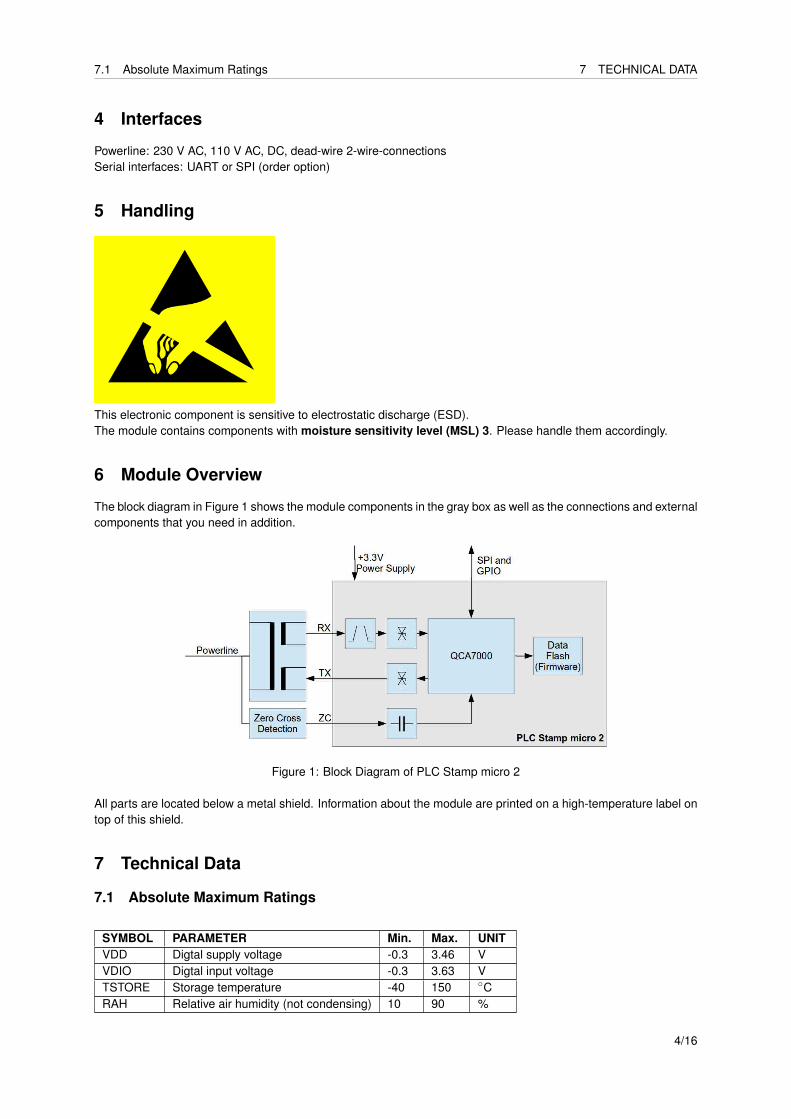
6 Module Overview
The block diagram in Figure 1 shows the module components in the gray box as well as the connections and externalcomponents that you need in addition.
Figure 1: Block Diagram of PLC Stamp micro 2
All parts are located below a metal shield. Information about the module are printed on a high-temperature label ontop of this shield.
7 Technical Data
7.1 Absolute Maximum Ratings
SYMBOL PARAMETER Min. Max. UNITVDD Digtal supply voltage -0.3 3.46 VVDIO Digtal input voltage -0.3 3.63 VTSTORE Storage temperature -40 150 ◦CRAH Relative air humidity (not condensing) 10 90 %
4/16
8 FIRMWARE AND MAC ADDRESSES
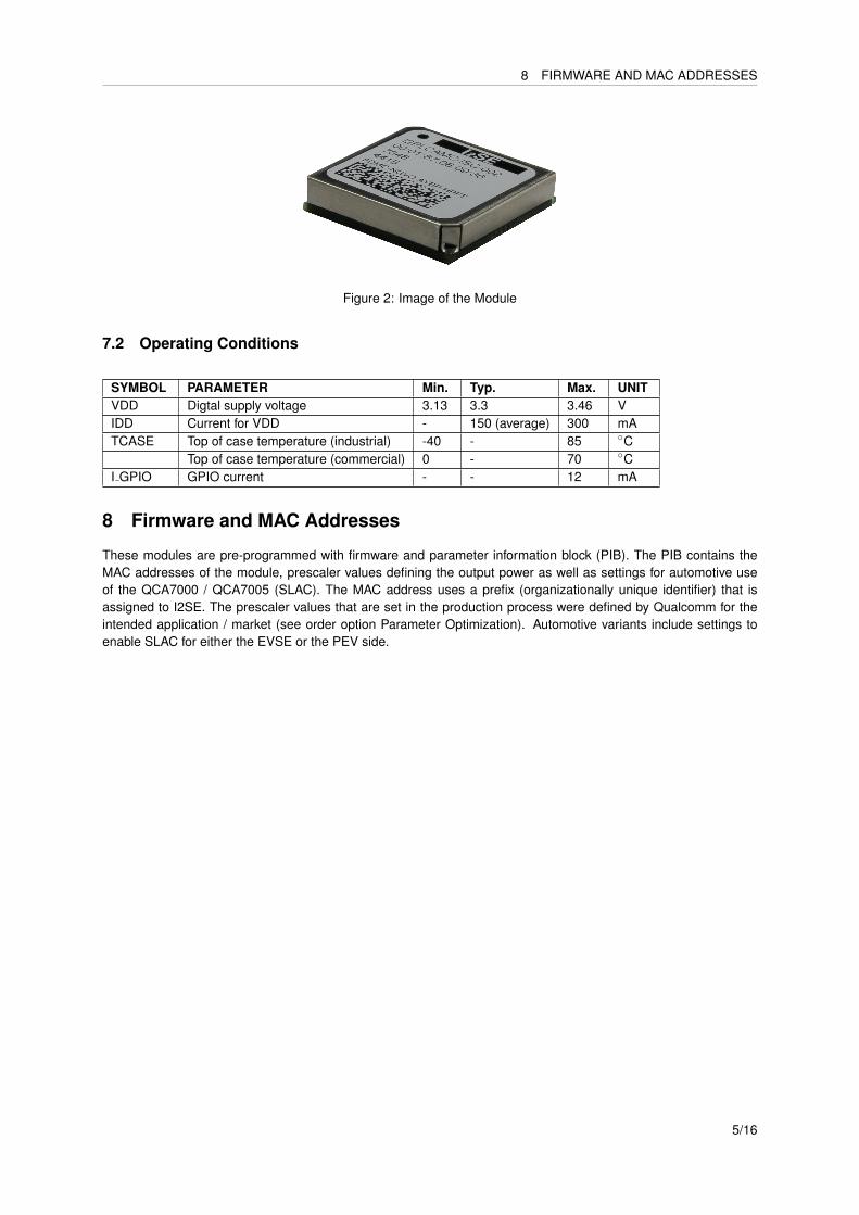
Figure 2: Image of the Module
7.2 Operating Conditions
SYMBOL PARAMETER Min. Typ. Max. UNITVDD Digtal supply voltage 3.13 3.3 3.46 VIDD Current for VDD - 150 (average) 300 mATCASE Top of case temperature (industrial) -40 - 85 ◦C
Top of case temperature (commercial) 0 - 70 ◦CI GPIO GPIO current - - 12 mA
8 Firmware and MAC Addresses
These modules are pre-programmed with firmware and parameter information block (PIB). The PIB contains theMAC addresses of the module, prescaler values defining the output power as well as settings for automotive useof the QCA7000 / QCA7005 (SLAC). The MAC address uses a prefix (organizationally unique identifier) that isassigned to I2SE. The prescaler values that are set in the production process were defined by Qualcomm for theintended application / market (see order option Parameter Optimization). Automotive variants include settings toenable SLAC for either the EVSE or the PEV side.
5/16
9.1 GPIO 9 MODULE PINOUT
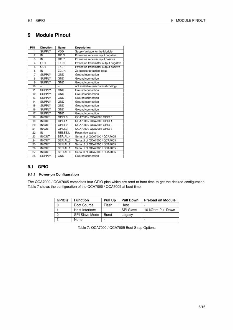
9 Module Pinout
PIN Direction Name Description1 SUPPLY VDD Supply Voltage for the Module2 IN RX N Powerline receiver input negative3 IN RX P Powerline receiver input positive4 OUT TX N Powerline transmitter output negative5 OUT TX P Powerline transmitter output positive6 IN ZC IN Zerocross detection input7 SUPPLY GND Ground connection8 SUPPLY GND Ground connection9 SUPPLY GND Ground connection
10 – – not available (mechanical coding)11 SUPPLY GND Ground connection12 SUPPLY GND Ground connection13 SUPPLY GND Ground connection14 SUPPLY GND Ground connection15 SUPPLY GND Ground connection16 SUPPLY GND Ground connection17 SUPPLY GND Ground connection18 IN/OUT GPIO 0 QCA7000 / QCA7005 GPIO 019 IN/OUT GPIO 1 QCA7000 / QCA7005 GPIO 120 IN/OUT GPIO 2 QCA7000 / QCA7005 GPIO 221 IN/OUT GPIO 3 QCA7000 / QCA7005 GPIO 322 IN RESET L Reset (low active)23 IN/OUT SERIAL 4 Serial 4 of QCA7000 / QCA700524 IN/OUT SERIAL 3 Serial 3 of QCA7000 / QCA700525 IN/OUT SERIAL 2 Serial 2 of QCA7000 / QCA700526 IN/OUT SERIAL 1 Serial 1 of QCA7000 / QCA700527 IN/OUT SERIAL 0 Serial 0 of QCA7000 / QCA700528 SUPPLY GND Ground connection
9.1 GPIO
9.1.1 Power-on Configuration
The QCA7000 / QCA7005 comprises four GPIO pins which are read at boot time to get the desired configuration.Table 7 shows the configuration of the QCA7000 / QCA7005 at boot time.
GPIO # Function Pull Up Pull Down Preload on Module0 Boot Source Flash Host -1 Host Interface - SPI Slave 10 kOhm Pull Down2 SPI Slave Mode Burst Legacy -3 None - - -
Table 7: QCA7000 / QCA7005 Boot Strap Options
6/16
9.2 Serial Signals 9 MODULE PINOUT
9.1.2 GPIO Functions
The GPIOs of the QCA7000 / QCA7005 have different functions after booting. They can either be used as input oroutput to display various states or trigger some actions. It is not possible to use these pins from your own application- only the QCA7000 / QCA7005 firmware can control these GPIOs. The GPIOs are set up as noted in Table 9.
GPIO # Direction Function0 Output PLC connection (1=connection established, 0=no
connection)1 Output Pushbutton Simple Connect (toggling 1/0 with
1Hz: simple connect mode active, 0: not in sim-ple connect mode)
2 Output unused in default configuration3 Input Pushbutton Simple Connect (hold time: 0.5 to 3s),
NMK randomize (hold time: 5 to 8s), Factory de-faults (hold time: 10 to 15s)
Table 9: QCA7000 / QCA7005 GPIO Settings
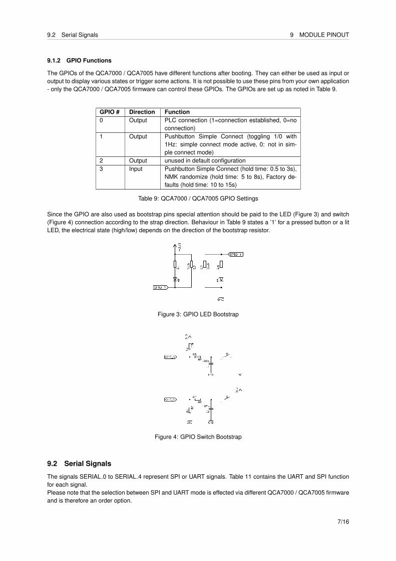
Since the GPIO are also used as bootstrap pins special attention should be paid to the LED (Figure 3) and switch(Figure 4) connection according to the strap direction. Behaviour in Table 9 states a ’1’ for a pressed button or a litLED, the electrical state (high/low) depends on the direction of the bootstrap resistor.
Figure 3: GPIO LED Bootstrap
Figure 4: GPIO Switch Bootstrap
9.2 Serial Signals
The signals SERIAL 0 to SERIAL 4 represent SPI or UART signals. Table 11 contains the UART and SPI functionfor each signal.Please note that the selection between SPI and UART mode is effected via different QCA7000 / QCA7005 firmwareand is therefore an order option.
7/16
9.2 Serial Signals 9 MODULE PINOUT
Signal Name SPI function UART functionSERIAL 0 InterruptSERIAL 1 CLK RTSSERIAL 2 CS CTSSERIAL 3 MISO TXDSERIAL 4 MOSI RXD
Table 11: QCA7000 / QCA7005 UART/SPI Signals
9.2.1 UART
All module variants in UART mode use the settings in Table 13. Pins RTS and CTS are not used.
Setting ValueBaud Rate 115200Data Bits 8Parity NoneStop Bits 1Flow Control None
Table 13: UART Settings
9.2.2 SPI
The QCA7000 / QCA7005 uses SPI in mode 3: CPOL=1, CPHA=1.SPI should be used in burst mode, meaning that the Chip Select signal is kept low during a complete SPI message.The SPI CLK period should not be less than 83.3 ns resulting in a maximum clock frequency of 12 MHz.
8/16
9.3 Recommended Footprint 10 GETTING STARTED
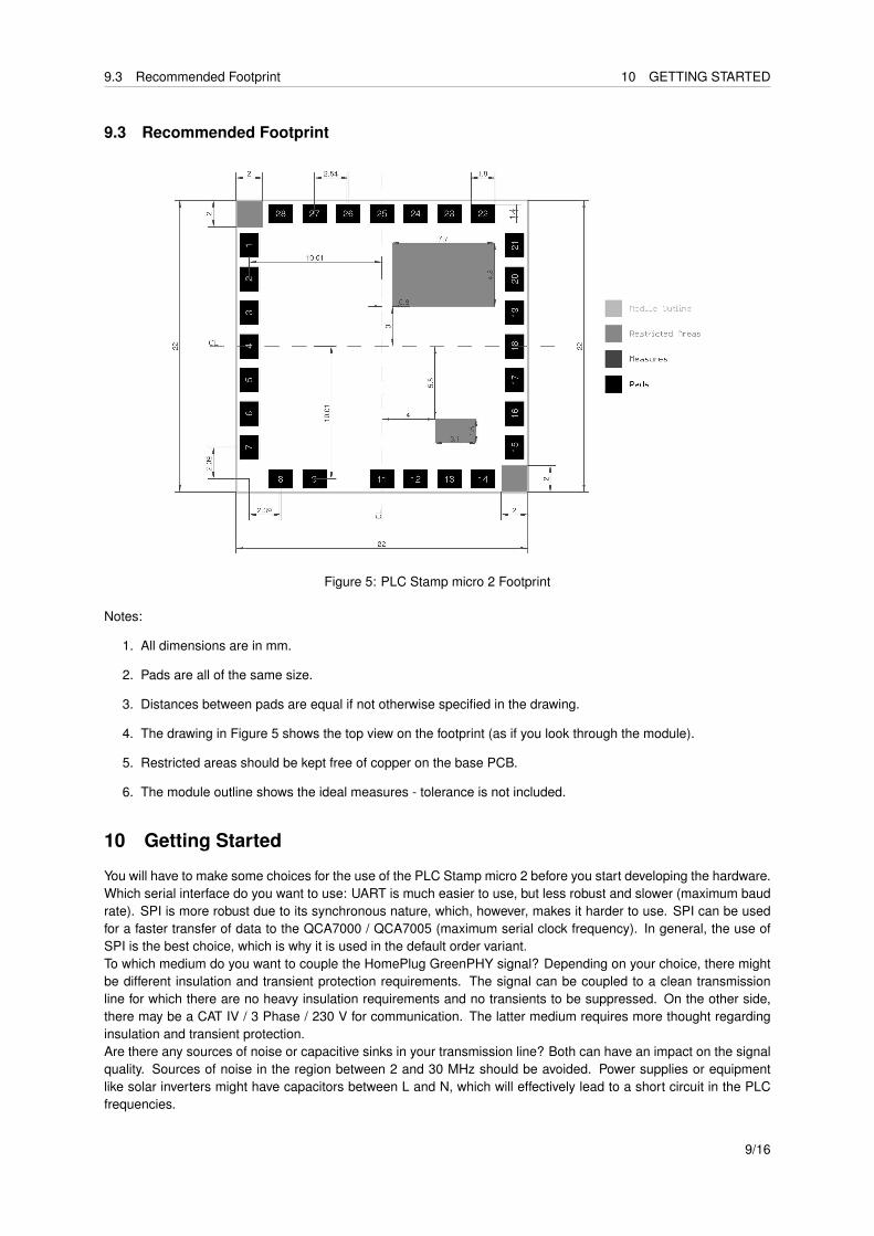
9.3 Recommended Footprint
Figure 5: PLC Stamp micro 2 Footprint
Notes:
1. All dimensions are in mm.
2. Pads are all of the same size.
3. Distances between pads are equal if not otherwise specified in the drawing.
4. The drawing in Figure 5 shows the top view on the footprint (as if you look through the module).
5. Restricted areas should be kept free of copper on the base PCB.
6. The module outline shows the ideal measures - tolerance is not included.
10 Getting Started
You will have to make some choices for the use of the PLC Stamp micro 2 before you start developing the hardware.Which serial interface do you want to use: UART is much easier to use, but less robust and slower (maximum baudrate). SPI is more robust due to its synchronous nature, which, however, makes it harder to use. SPI can be usedfor a faster transfer of data to the QCA7000 / QCA7005 (maximum serial clock frequency). In general, the use ofSPI is the best choice, which is why it is used in the default order variant.To which medium do you want to couple the HomePlug GreenPHY signal? Depending on your choice, there mightbe different insulation and transient protection requirements. The signal can be coupled to a clean transmissionline for which there are no heavy insulation requirements and no transients to be suppressed. On the other side,there may be a CAT IV / 3 Phase / 230 V for communication. The latter medium requires more thought regardinginsulation and transient protection.Are there any sources of noise or capacitive sinks in your transmission line? Both can have an impact on the signalquality. Sources of noise in the region between 2 and 30 MHz should be avoided. Power supplies or equipmentlike solar inverters might have capacitors between L and N, which will effectively lead to a short circuit in the PLCfrequencies.
9/16
10 GETTING STARTED
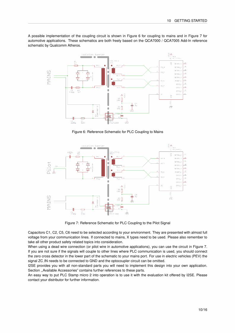
A possible implementation of the coupling circuit is shown in Figure 6 for coupling to mains and in Figure 7 forautomotive applications. These schematics are both freely based on the QCA7000 / QCA7005 Add-In referenceschematic by Qualcomm Atheros.
Figure 6: Reference Schematic for PLC Coupling to Mains
Figure 7: Reference Schematic for PLC Coupling to the Pilot Signal
Capacitors C1, C2, C5, C6 need to be selected according to your environment. They are presented with almost fullvoltage from your communication lines. If connected to mains, X types need to be used. Please also remember totake all other product safety related topics into consideration.When using a dead wire connection (or pilot wire in automotive applications), you can use the circuit in Figure 7.If you are not sure if the signals will couple to other lines where PLC communication is used, you should connectthe zero cross detector in the lower part of the schematic to your mains port. For use in electric vehicles (PEV) thesignal ZC IN needs to be connected to GND and the optocoupler circuit can be omitted.I2SE provides you with all non-standard parts you will need to implement this design into your own application.Section ,,Available Accessories” contains further references to these parts.An easy way to put PLC Stamp micro 2 into operation is to use it with the evaluation kit offered by I2SE. Pleasecontact your distributor for further information.
10/16
12 MODULE MARKING
11 Processing
• Process the modules according to IPC/JEDEC J–STD-020 and J-STD-033 guidelines.
• Limit repeated reflow processes to maximum 2.
12 Module Marking
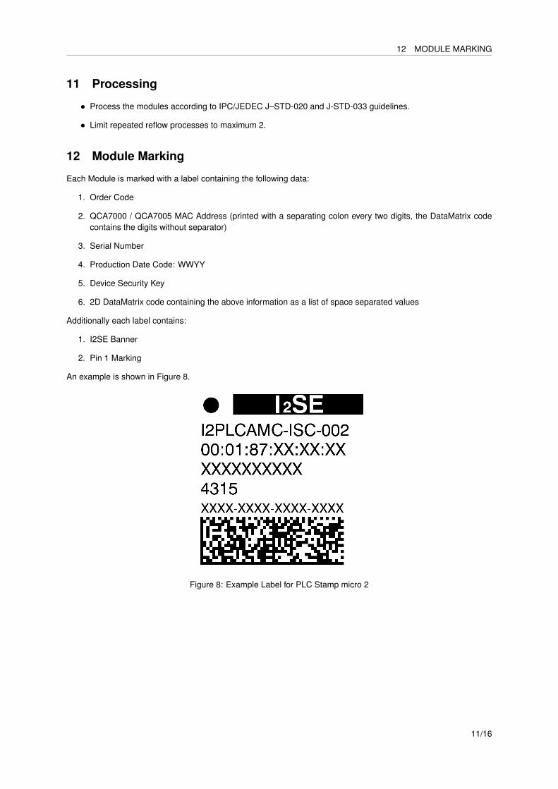
Each Module is marked with a label containing the following data:
1. Order Code
2. QCA7000 / QCA7005 MAC Address (printed with a separating colon every two digits, the DataMatrix codecontains the digits without separator)
3. Serial Number
4. Production Date Code: WWYY
5. Device Security Key
6. 2D DataMatrix code containing the above information as a list of space separated values
Additionally each label contains:
1. I2SE Banner
2. Pin 1 Marking
An example is shown in Figure 8.
Figure 8: Example Label for PLC Stamp micro 2
11/16
13 ORDER INFORMATION
13 Order Information
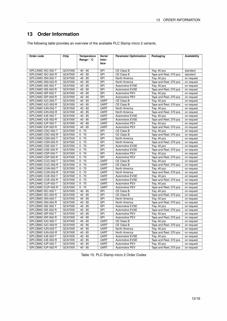
The following table provides an overview of the available PLC Stamp micro 2 variants.
Order code Chip TemperatureRange / ◦C
SerialInter-face
Parameter Optimization Packaging Availability
I2PLCAMC-ISC-002-T QCA7000 -40 - 85 SPI CE Class B Tray, 40 pcs standardI2PLCAMC-ISC-002-R QCA7000 -40 - 85 SPI CE Class B Tape and Reel, 370 pcs standardI2PLCAMC-ISN-002-T QCA7000 -40 - 85 SPI North America Tray, 40 pcs on requestI2PLCAMC-ISN-002-R QCA7000 -40 - 85 SPI North America Tape and Reel, 370 pcs on requestI2PLCAMC-ISE-002-T QCA7000 -40 - 85 SPI Automotive EVSE Tray, 40 pcs on requestI2PLCAMC-ISE-002-R QCA7000 -40 - 85 SPI Automotive EVSE Tape and Reel, 370 pcs on requestI2PLCAMC-ISP-002-T QCA7000 -40 - 85 SPI Automotive PEV Tray, 40 pcs on requestI2PLCAMC-ISP-002-R QCA7000 -40 - 85 SPI Automotive PEV Tape and Reel, 370 pcs on requestI2PLCAMC-IUC-002-T QCA7000 -40 - 85 UART CE Class B Tray, 40 pcs on requestI2PLCAMC-IUC-002-R QCA7000 -40 - 85 UART CE Class B Tape and Reel, 370 pcs on requestI2PLCAMC-IUN-002-T QCA7000 -40 - 85 UART North America Tray, 40 pcs on requestI2PLCAMC-IUN-002-R QCA7000 -40 - 85 UART North America Tape and Reel, 370 pcs on requestI2PLCAMC-IUE-002-T QCA7000 -40 - 85 UART Automotive EVSE Tray, 40 pcs on requestI2PLCAMC-IUE-002-R QCA7000 -40 - 85 UART Automotive EVSE Tape and Reel, 370 pcs on requestI2PLCAMC-IUP-002-T QCA7000 -40 - 85 UART Automotive PEV Tray, 40 pcs on requestI2PLCAMC-IUP-002-R QCA7000 -40 - 85 UART Automotive PEV Tape and Reel, 370 pcs on requestI2PLCAMC-CSC-002-T QCA7000 0 - 70 SPI CE Class B Tray, 40 pcs on requestI2PLCAMC-CSC-002-R QCA7000 0 - 70 SPI CE Class B Tape and Reel, 370 pcs on requestI2PLCAMC-CSN-002-T QCA7000 0 - 70 SPI North America Tray, 40 pcs on requestI2PLCAMC-CSN-002-R QCA7000 0 - 70 SPI North America Tape and Reel, 370 pcs on requestI2PLCAMC-CSE-002-T QCA7000 0 - 70 SPI Automotive EVSE Tray, 40 pcs on requestI2PLCAMC-CSE-002-R QCA7000 0 - 70 SPI Automotive EVSE Tape and Reel, 370 pcs on requestI2PLCAMC-CSP-002-T QCA7000 0 - 70 SPI Automotive PEV Tray, 40 pcs on requestI2PLCAMC-CSP-002-R QCA7000 0 - 70 SPI Automotive PEV Tape and Reel, 370 pcs on requestI2PLCAMC-CUC-002-T QCA7000 0 - 70 UART CE Class B Tray, 40 pcs on requestI2PLCAMC-CUC-002-R QCA7000 0 - 70 UART CE Class B Tape and Reel, 370 pcs on requestI2PLCAMC-CUN-002-T QCA7000 0 - 70 UART North America Tray, 40 pcs on requestI2PLCAMC-CUN-002-R QCA7000 0 - 70 UART North America Tape and Reel, 370 pcs on requestI2PLCAMC-CUE-002-T QCA7000 0 - 70 UART Automotive EVSE Tray, 40 pcs on requestI2PLCAMC-CUE-002-R QCA7000 0 - 70 UART Automotive EVSE Tape and Reel, 370 pcs on requestI2PLCAMC-CUP-002-T QCA7000 0 - 70 UART Automotive PEV Tray, 40 pcs on requestI2PLCAMC-CUP-002-R QCA7000 0 - 70 UART Automotive PEV Tape and Reel, 370 pcs on requestI2PLCBMC-ISC-002-T QCA7005 -40 - 85 SPI CE Class B Tray, 40 pcs on requestI2PLCBMC-ISC-002-R QCA7005 -40 - 85 SPI CE Class B Tape and Reel, 370 pcs on requestI2PLCBMC-ISN-002-T QCA7005 -40 - 85 SPI North America Tray, 40 pcs on requestI2PLCBMC-ISN-002-R QCA7005 -40 - 85 SPI North America Tape and Reel, 370 pcs on requestI2PLCBMC-ISE-002-T QCA7005 -40 - 85 SPI Automotive EVSE Tray, 40 pcs on requestI2PLCBMC-ISE-002-R QCA7005 -40 - 85 SPI Automotive EVSE Tape and Reel, 370 pcs on requestI2PLCBMC-ISP-002-T QCA7005 -40 - 85 SPI Automotive PEV Tray, 40 pcs on requestI2PLCBMC-ISP-002-R QCA7005 -40 - 85 SPI Automotive PEV Tape and Reel, 370 pcs on requestI2PLCBMC-IUC-002-T QCA7005 -40 - 85 UART CE Class B Tray, 40 pcs on requestI2PLCBMC-IUC-002-R QCA7005 -40 - 85 UART CE Class B Tape and Reel, 370 pcs on requestI2PLCBMC-IUN-002-T QCA7005 -40 - 85 UART North America Tray, 40 pcs on requestI2PLCBMC-IUN-002-R QCA7005 -40 - 85 UART North America Tape and Reel, 370 pcs on requestI2PLCBMC-IUE-002-T QCA7005 -40 - 85 UART Automotive EVSE Tray, 40 pcs on requestI2PLCBMC-IUE-002-R QCA7005 -40 - 85 UART Automotive EVSE Tape and Reel, 370 pcs on requestI2PLCBMC-IUP-002-T QCA7005 -40 - 85 UART Automotive PEV Tray, 40 pcs on requestI2PLCBMC-IUP-002-R QCA7005 -40 - 85 UART Automotive PEV Tape and Reel, 370 pcs on request
Table 15: PLC Stamp micro 2 Order Codes
12/16
13.1 Available Accessories 13 ORDER INFORMATION
ProductFamilyCode
Chip Temperature Range SerialInter-face
Parameter Optimization Version Packaging
I2PLC A: QCA7000 MC- I: Industrial (-40 - 85 ◦C) S: SPI C: CE Class B -002 -T: Tray, 20 pcsB: QCA7005 C: Commercial tempera-
ture range (0 - 70 ◦C) - onlyfor QCA7000
U: UART N: north america -R: Tape andReel: 370pcs
E: Automotive EVSEP: Automotive PEV
Table 17: PLC Stamp micro 2 Order Code Compilation
13.1 Available Accessories
I2SE provides you with tested powerline transformers, which are part of the reference designs. Please refer tofurther documentation for a full specification of these transformers.
Version Order Code1:4:5 for mains power line coupling I2PLCTR-11:1:1 for Electric Vehicle (PEV) and Electric Vehicle Supply Equipment (EVSE) I2PLCTR-2
13/16
14.1 Tape and Reel 14 PACKAGE MATERIALS INFORMATION
14 Package Materials Information
14.1 Tape and Reel
Tape and Reel according to EIA-481
Ao 22,6 ± 0,15Bo 22,7 ± 0,15Do Ø1,5 + 0,1D1 Ø2,0 MINE1 1,75 ± 0,10F (III) 20,20 ± 0,15Ko 5,80 ± 0,15K1 4,80 ± 0,15Po (II) 4,00 ± 0,15P1 28,00 ± 0,15P2 (I) 2,00 ± 0,15So 40,40 ± 0,15T 0,40 ± 0,04W 44,0 ± 0,3
All dimensions in millimeters unless otherwise stated.Material: Polystyrene
(I ) Measured from centreline of sprocket hole to centreline of pocket(II ) Cumulative tolerance of 10 sprocket holes is ± 0,20(III) Measured from centreline of sprocket hole to centreline of sprocket
Reel Dimensions
Reel inner Diameter 4”Reel outer Diameter 13”Reel inner Width 44Parts/Carrier Tape-Reel 370Tape leader empty cavities 7..12Tape trailer empty cavities 7..12
14/16
14.3 Tape and Reel Cardboard Box Dimensions 14 PACKAGE MATERIALS INFORMATION
14.2 Orientation of the Module
14.3 Tape and Reel Cardboard Box Dimensions
H 65 mmW 340 mmL 340 mm
15/16
15 CONTACT
15 Contact
Website: http://www.i2se.comI2SE GmbHFriedrich-Ebert-Str. 6104109 LeipzigGermany
16/16


![arXiv:1908.09428v1 [cs.CV] 26 Aug 2019 · Email address: hafeez.anwar@fau.de (Hafeez Anwar) 1Shows equal contribution arXiv:1908.09428v1 [cs.CV] 26 Aug 2019. verse motifs. On this](https://static.fdocuments.net/doc/165x107/5fb46ee46673cd062e3628ef/arxiv190809428v1-cscv-26-aug-2019-email-address-faude-hafeez-anwar-1shows.jpg)