PLC BASED SPECIAL PURPOSE EQUIPMENTS · plc based special purpose equipments sdsc shar, isro sdsc...
126
PLC BASED SPECIAL PURPOSE EQUIPMENTS SDSC SHAR, ISRO SDSC SHAR, Sriharikota REQUEST FOR PROPOSAL For DESIGN, MANUFACTURE, TESTING AT SHOP FLOOR, SUPPLY, INSTALLATION AT SITE, TESTING AND COMMISSIONING OF PLC BASED SPECIAL PURPOSE EQUIPMENTS Satish Dhawan Space Centre SHAR Indian Space Research Organization Sriharikota - 524 124, A.P
Transcript of PLC BASED SPECIAL PURPOSE EQUIPMENTS · plc based special purpose equipments sdsc shar, isro sdsc...
PLC BASED SPECIAL PURPOSE EQUIPMENTS SDSC SHAR, ISRO
SDSC SHAR, Sriharikota
REQUEST FOR PROPOSAL
For
DESIGN, MANUFACTURE, TESTING AT SHOP FLOOR, SUPPLY, INSTALLATION AT SITE, TESTING AND COMMISSIONING
OF
PLC BASED SPECIAL PURPOSE
EQUIPMENTS
Satish Dhawan Space Centre SHAR
Indian Space Research Organization Sriharikota - 524 124, A.P
i
PLC BASED SPECIAL PURPOSE EQUIPMENTS SDSC SHAR, ISRO
Contents
S.NO DESCRIPTION PAGE NO.
1.0 PROPOSAL DOCUMENT …………………………………………............................. 1
2.0 ADDENDA / CORRIGENDA………………………………………………………….. 3
2.1 AMBIGUITY ………………………………………………………………................... 3
3.0 PREPARATION OF BIDS……………………………………………………………... 3
3.1 SITE VISIT …………………………………………………………………………….. 3
3.2 VALIDITY OF OFFER ……………………………………………………................... 3
3.3 COST OF BIDDING ………………………………………………………………….. 4
3.4 PROJECT MONITORING ……………………………………………….................... 4
3.5 APPLICABLE LANGUAGE …………………………………………….................... 4
3.6 ARRANGEMENT OF BID ……………………………………………………………. 4
3.7 SCHEDULE OF PRICES ………………………………………………….................... 5
3.8 DOCUMENTS COMPRISING THE BID ……………………………………………... 5
3.8.1 PART – I TECHNICAL AND UNPRICED COMMERCIAL PART………………….. 6
3.8.2 PART – II PRICED COMMERCIAL BID …………………………………………….. 6
3.8.3 BID SUBMISSION …………………………………………………………………….. 7
3.8.4 BID EVALUATION……………………………………………………………………. 7
4.0 EXCLUSION OF TENDERS ……………………………………………................... 8
5.0 DRAWINGS ………………………………………………………………………….. 9
6.0 PUBLICITY RELATING TO TENDERS ……………………………………………. 9
7.0 MINIMUM CRITERIA FOR QUALIFICATION ……………………………………. 10
8.0 DETERMINATION OF RESPONSIVENESS ………………………………………… 11
9.0 VENDOR EVALUATION FORMAT …………………………………….................... 11
9.1 FOR INDIGENOUS VENDORS ………………………………………….................... 11
9.2 FOR FOREIGN VENDORS …………………………………………………………… 14
SECTION A: GENERAL TERMS AND CONDITIONS OF CONTRACT
1.0 INTRODUCTION ……..……………………………………………………………….. 19
ii
PLC BASED SPECIAL PURPOSE EQUIPMENTS SDSC SHAR, ISRO
2.0 SCOPE OF WORK AND TECHNICAL SPECIFICATIONS…………………………. 19
3.0 SUPPLIER'S OBLIGATIONS & FUNCTIONS ………………………………………. 19
3.1 SPECIFICATIONS AND DRAWINGS ……………………………………………….. 19
3.2 APPROVAL OF TECHNICAL DOCUMENTS / DRAWINGS………………………. 19
3.3 DESIGN & SUPPLY OF EQUIPMENT …………………………………................... 19
3.4 INSPECTION AND TESTING ………………………………………………………... 20
3.5 DELIVERY AND STORAGE ………………………………………………………… 21
4.0 INSTALLATION ……………………………………………………………………… 22
4.1 GENERAL ……………………………………………………………………………... 22
4.2 SETTING OUT, LEVELLING AND GROUTING OF EQUIPMENT ………………. 23
4.3 RECORDS ……………………………………………………………………………... 23
4.4 EQUIPMENT ERECTION ……………………………………………………………. 24
5.0 DRAWINGS AND O&M MANUALS ……………………………………………….. 24
6.0 MAINTENANCE SERVICES …………………………………………………………. 25
7.0 TRAINING …………………………………………………………………………….. 25
8.0 SCHEDULE OF PRICE ……………………………………………………………….. 25
9.0 DISCOUNTS …………………………………………………………………………... 26
10.0 MODE OF PAYMENT…………………………………………………………………. 27
11.0 TERMS OF PAYMENTS ……………………………………………………………… 27
12.0 DELIVERY SCHEDULE ……………………………………………………………… 27
13.0 LIQUIDATED DAMAGES ………………………………………………………......... 27
14.0 EXTENSION OF TIME ……………………………………………………………….. 28
15.0 FOREIGN EXCHANGE OUTGO AND VARIATION ……………………………….. 28
16.0 TAXES AND DUTIES ………………………………………………………………… 28
16.1 GST ……………………………………………………………………………………. 28
16.2 CUSTOMS DUTY ……………………………………………………………………... 29
16.3 INCOME TAX ………………………………………………………………………… 29
16.4 EARNEST MONEY DEPOSIT (EMD) ……………………………………………….. 29
17.0 RISK COVERAGE ……………………………………………………………………. 30
18.0 SECURITY DEPOSIT …………………………………………………………………. 30
iii
PLC BASED SPECIAL PURPOSE EQUIPMENTS SDSC SHAR, ISRO
19.0 PACKING AND FORWARDING …………………………………………………….. 30
20.0 WARRANTY …………………………………………………………………………... 31
21.0 GUARANTEE …………………………………………………………………………. 32
22.0 PERFORMANCE BANK GUARANTEE ……………………………………………. 32
23.0 DISCLOSURE AND USE OF INFORMATION BY THE SUPPLIER ………………. 32
24.0 ARBITRATION ………………………………………………………………………... 32
25.0 APPLICABLE LAW AND JURISDICTION …………………………………………. 34
26.0 FORCE MAJEURE ……………………………………………………………………. 34
27.0 GENERAL ……………………………………………………………………………... 34
27.1 SITE DETAIL …………………………………………………………………………. 34
27.2 SAFETY ………………………………………………………………………………... 34
27.3 POWER SUPPLY ……………………………………………………………………… 35
27.4 WORK RULES ………………………………………………………………………… 35
27.5 SITE CLEARANCE …………………………………………………………………… 35
27.6 ACCOMMODATION ………………………………………………………………… 35
27.7 MEDICAL FACILITIES ………………………………………………………………. 35
27.8 WORK PROGRAMME ………………………………………………………………. 35
27.9 SUB-CONTRACTS ……………………………………………………………………. 36
27.10 CHANGES AND MODIFICATION TO SPECIFICATIONS, DESIGNS,
DRAWINGS AND QUALITATIVE / QUANTITATIVE REQUIREMENTS ……….
36
27.11 ACCEPTANCE AND REJECTION …………………………………………………… 37
27.12 SUSPENSION …………………………………………………………………………. 38
27.13 CANCELLATION ……………………………………………………………………... 38
28.0 EQUIPMENTS AND SERVICES ……………………………………………………... 40
29.0 CODES AND STANDARDS …………………………………………………………. 40
30.0 GENERAL SPECIFICTIONS RELATED TO FABRICATION ……………………… 41
SECTION-B : SCOPE OF WORK
1.0 INTRODUCTION ……………………………………………………………………… 43
2.0 SCOPE OF WORK ……………………………………………………………………. 43
iv
PLC BASED SPECIAL PURPOSE EQUIPMENTS SDSC SHAR, ISRO
3.0 VENDOR’S SCOPE OF WORK ………………………………………………………. 43
4.0 WORKS UNDER PURCHASER’S SCOPE …………………………………………... 45
SECTION-C : TECHNICAL SPECIFICATIONS
I : GENERAL TECHNICAL SPECIFICATIONS
1.0 SCOPE …………………………………………………………………………………. 47
2.0 DESCRIPTION OF NDT PROCESS………………………………………………….. 48
3.0 FUNCTION OF FPS & ESS AND USER’S REQUIREMENT………………………. 51
3.1 FUNCTIONS OF FPS & ESS…………………………………………………………. 51
3.2 OTHER CONSIDERATIONS……………………………………………………….... 53
3.3 USER’S REQUIREMENTS…………………………………………………………… 53
4.0 DESIGN CRITERIA…………………………………………………………………… 54
5.0 EQUIPMENT AND SERVICES TO BE PROVIDED BY THE SUPPLIER ……….. 54
6.0 EQUIPMENT & SERVICES TO BE PROVIDED BY PURCHASER …………........ 57
7.0 CODES AND STANDARDS…………………………………………………………... 57
8.0 CONFIGURATION OF FPS & ESS…………………………………………………… 58
8.1 GENERAL ARRANGEMENT DRAWING OF FPS…………………………............. 59
8.2 GENERAL ARRANGEMENT DRAWING OF FPS X & Y-TABLES……………….. 59
8.3 FPS X-TABLE ASSEMBLY……………………………………………….................... 59
8.4 FPS Y-TABLE ASSEMBLY…………………………………………………………… 59
8.5 RAIL LAYOUT………………………………………… ……………………………… 59
8.6 CASSETTE HOLDER ………………………………………………………………… 59
8.7 FPS ROOM …………………………………………………………………………….. 59
8.8 BOOM DRIVE SYSTEM ……………………………………….................................. 60
8.9 CASSETTE SLIDE OR C-SLIDE …………………………………………………….. 60
v
PLC BASED SPECIAL PURPOSE EQUIPMENTS SDSC SHAR, ISRO
8.10 LOADER AND UN-LOADER CABINETS …………………………………………... 60
8.11 COLUMN ASSEMBLY………………………………………………………………... 61
8.12 END SUPPORT SYSTEM DRAWINGS ………………………………….................. 61
9.0 FPS AND ESS CABLE SYSTEM ……………………………………………………... 61
10.0 OPERATION SEQUENCE AND INTERLOCKS …………………………………….. 61
10.1 FILM POSITIONING SYSTEM……………………………………………………….. 61
10.2 END SUPPORT SYSTEM……………………………………………………………... 62
10.3 PRELIMINARY PREPARATION……………………………………………………... 62
10.4 PREPARATION FOR PROPELLANT RADIOGRAPHY…………………………….. 62
10.5 FOR TANGENTIAL RADIOGRAPHY……………………………………………….. 63
11.0 PRELIMINARY SPECIFICATIONS OF MAJOR SUB-SYSTEMS………………….. 64
12.0 INTERFACE DETAILS BETWEEN ITEMS / SUB-SYSTEMS / SYSTEMS……….. 65
13.0 COMPLIANCE OF SPECIFICATIONS & USER REQUIREMENTS……………...... 66
14.0 ERECTION SEQUENCE………………………………………………………………. 66
15.0 PAINTING……………………………………………………………………………… 66
16.0 SUMMARY OF DATA TO BE FURNISHED ALONG WITH BID AND AFTER
PLACEMENT OF ORDER……………………………………………………………. 67
17.0 DETAILED ENGINEERING DOCUMENTS AFTER ISSUE OF LETTER OF
INTENT (LOI)………………………………………………………………………….. 68
17.1 FINAL DOCUMENTS…………………………………………………………………. 68
18.0 BOUGHT OUT ITEMS………………………………………………………………… 68
19.0 GENERAL INSTRUCTIONS / REQUIREMENTS………………………………........ 69
II : ELECTRICAL SPECIFICATIONS 71
III : SPECIFICATIONS OF INSTRUMENTATION & CONTROL S YSTEMS
1.1 LOCAL OPERATING STATION……………………………………………………… 94
vi
PLC BASED SPECIAL PURPOSE EQUIPMENTS SDSC SHAR, ISRO
1.2 FILM POSITIONING SYSTEM (FPS)……………………………………………….. 94
1.2.1 FPS X TRAVEL MOTION…………………………………………………………….. 94
1.2.2 FPS Y-TRAVEL……………………………………………………………................... 95
1.2.3 FPS C-SLIDE……………………………………………………………........................ 96
1.2.4 LOADER & UN-LOADER CABINET SYSTEM……………………………………... 97
1.2.5 FPS BOOM……………………………………………………………………………... 98
1.2.6 OTHER INSTRUMENTS……………………………………………………………… 100
1.3 END SUPPORT SYSTEM (ESS)………………………………………………………. 100
1.3.1 ESS Y-TRAVEL ……..................................................................................................... 100
1.3.2 ESS Z-SLIDE…………………………………………………………………………… 101
2.0 SPECIFICATIONS OF I & C ITEMS…………………………………………………. 102
2.1 PLC …………………………………………………………………………………..... 102
2.2 SCADA & HMI REQUIREMENTS…………………………………………….......... 103
2.3 POWER SUPPLY ITEMS……………………………………………………………… 102
2.4 FIELD INSTRUMENTS ………………………………………………………………. 103
2.4.1 EX-PROOF ABSOLUTE ENCODERS ……………………………………………….. 103
2.4.2 PROXIMITY SENSORS ………………………………………………………………. 104
2.4.3 DIGITAL INPUT ISOLATOR ………………………………………………………… 104
2.4.4 DIGITAL OUTPUT ISOLATOR ……………………………………………………… 104
3.0 EX-PROOF CAMERAS AND CCTV SYSTEMS ……………………………………. 104
4.0 OVERALL CONTROL SYSTEM …………………………………………………...... 105
5.0 SPARES TO BE SUPPLIED …………………………………………………………... 106
6.0 SPECIFICATIONS OF CONTROL DESK ……………………………………………. 106
7.0 DELIVERY AND WARRANTY ……………………………………………………… 106
8.0 ELECTRICAL CABLES ANNEXURE………………………………………………... 107
vii
PLC BASED SPECIAL PURPOSE EQUIPMENTS SDSC SHAR, ISRO
8.1 TECHNICAL SPECIFICATIONS OF LT POWER CABLES………………………… 107
8.2 CONSTRUCTION SPECIFICATIONS-1 ……………………………………………... 107
8.2.1 CONSTRUCTION SPECIFICATION-2 ………………………………………………. 108
8.3 BILL OF QUANTITIES ……………………………………………………………… 108
8.4 TESTING ………………………………………………………………………………. 109
8.5 PACKING AND MARKING …………………………………………………………. 111
8.6 GENERAL NOTE TO SUPPLIERS …………………………………………………... 111
SECTION-D : ANNEXURES
ANNEXURE –I: SCHEDULE OF PRICES …………………………………………………… 115
ANNEXURE –II: EXCEPTIONS AND DEVIATIONS ……………………………………….. 116
ANNEXURE –III: CHECK LIST ……………………………………………………………….. 117
viii
PLC BASED SPECIAL PURPOSE EQUIPMENTS SDSC SHAR, ISRO
Acronyms
ISRO Indian Space Research Organization
SDSC Satish Dhawan Space Centre
CISF Central Industrial Security Force
CCW Counter Clockwise
CW Clockwise
PCC Power Control Centre ( electrical )
PLC Programmable Logic Control
LC Letter of Credit
CCTV Close Circuit Television
AMC Annual Maintenance Contract
GA (drawing) General Arrangement (drawing )
SS Stainless Steel
IP Ingress Protection
UPS Uninterrupted Power Supply
ECS Electronic Clearance System
FPS Film Positioning System
ESS End Support System
1
PLC BASED SPECIAL PURPOSE EQUIPMENTS SDSC SHAR, ISRO
PROPOSAL DOCUMENT, CLARIFICATION AND ADDENDUM
Proposals are invited from the interested Suppliers for the enclosed scope of work in two part
bid. Part-1 Technical and Unpriced part of the work and Part-2 Priced Commercial part.
The RFP document is organized in four sections as follows.
Section –A General Terms and Conditions of the Contract
Section –B Scope of Work
Section –C Technical Specifications
Section –D Annexure
Title of the Entity: SDSC SHAR , SRIHARIKOTA
Title of the proposal: “ PLC BASED SPECIAL PURPOSE EQUIPMENTS”.
Date of Public Notification issued:
Last Date of purchase / downloading tender Document:
Last date of submission of tender documents:
Place of submission of tender documents: SDSC SHAR, Sriharikota
1. PROPOSAL DOCUMENT
a) One set of proposal document along with the drawings is issued. Bidder shall sign and
stamp each page of tender as token of his acceptance & submit along with his offer.
Document shall be scanned and uploaded in e-procurement portal. In case it is not
possible to upload due to higher file size, hard copy of the balance documents
(without any price figures) shall be submitted physically before due date.
b) Transfer of tender document issued to one Bidder to another is not permissible.
c) Tender documents shall remain the property of Department and if obtained by one
intending Bidder shall not be utilized by another without the consent of the
Department.
d) The proposal shall be completely filled in all respects and shall be submitted together
with requisite information. Any offer incomplete in any particulars is liable for
rejection.
e) Bidders shall set their quotations in firm figures and without qualifications or
variations or additions in the terms of the Tender documents. Proposal containing
2
PLC BASED SPECIAL PURPOSE EQUIPMENTS SDSC SHAR, ISRO
qualifying expressions such as "subject to minimum acceptance" or "subject to prior
sale" or any other qualifying expressions or incorporating terms and conditions at
variance with the terms and conditions incorporated in the Tender documents are
liable to be rejected.
f) Cost quoted shall be firm and fixed.
g) Price maybe quoted in Indian National Rupee or foreign currency as applicable.
h) Satish Dhawan Space Centre – SHAR (SDSC-SHAR) Sriharikota is declared as
prohibited place under official secrets act 1923. Hence during execution of site works
necessary security requirements enforced by the department from time to time shall be
followed strictly.
i) Defects in the material like fractures, cracks, blow holes, laminations, pitting, etc., are
not allowed.
j) During the erection, testing and commissioning of structure at site in Sriharikota, the
supplier has to make his own arrangements for boarding, lodging and transportation
of his men and materials. However, subjected to availability, hostel accommodation
may be provided by the Purchaser (SDSC SHAR) on chargeable basis.
k) Free electricity and water will be provided by the Purchaser (SDSC SHAR) for the
erection, testing and commissioning works at the site. Bidder shall take into this while
quoting the price.
l) Tools and tackles, other than those mentioned under free issue items, required shall be
arranged by the party.
m) Before starting the site work (at SDSC SHAR), the party shall provide insurance as
per workman compensation act to all his personnel working at site in Sriharikota
against accidents. Till commissioning of structure, the safe storing and handling of
structure is in the scope of supplier. Insurance for the same shall be borne by the
party.
n) Quote shall be based on DDP / DAP Sriharikota.
o) All applicable taxes (like CGST/SGST/IGST/UGST, etc.) and duties applicable shall
be indicated clearly in quotation.
p) Transportation & Transit Insurance are fully in the scope of supplier and the same
shall be borne by the party.
3
PLC BASED SPECIAL PURPOSE EQUIPMENTS SDSC SHAR, ISRO
q) Necessary care shall be taken during erection and commissioning of Indigenous 400 t
capacity self-aligning type Roller stands at our site. Any damage to the property of
Department shall be adequately compensated by the Party.
2. ADDENDA /CORRIGENDA
Addenda/corrigenda to the tender document may be issued by SDSC SHAR prior to
the date of opening of the tenders, to clarify or reflect modifications in the contract
terms and conditions.
Such addendum/corrigenda will be distributed to each firm or person who had
purchased the tender documents.
2.1. AMBIGUITY
Should there be any ambiguity or doubt as to the meaning of any of the tender
clause/condition or if any further information is required, the matter shall be
immediately brought to the notice of Sr. Head, Purchase & Stores, SDSC SHAR in
writing for necessary clarifications prior to the opening of the tenders.
3. PREPARATION OF BIDS
3.1. SITE VISIT
a) Bidders visit and examine the site and its surrounding to familiarize them self of the
existing facilities and environment and may collect all other information which he
may require for preparing and submitting the Bid and entering into the tender if
required. Bidders shall visit within 15 days from the date of tender enquiry.
b) Claims and objections due to ignorance of existing conditions or inadequacy of
information will not be considered after submission of the Bid and during
implementation.
3.2. VALIDITY OF OFFER
a) Bid shall remain valid for acceptance for a period of six months from the due date of
submission of the Bid.
b) The Bidder shall not be entitled during the said period to revoke or cancel his Bid or
to vary the Bid except and to the extent required by Department in writing.
c) Bid shall be revalidated for extended period as required by Department in writing.
4
PLC BASED SPECIAL PURPOSE EQUIPMENTS SDSC SHAR, ISRO
d) In such cases, unless otherwise specified, it is understood that validity is sought and
provided without varying either the quoted price or any other terms and conditions of
Bid finalized till that time.
3.3. COST OF BIDDING
All direct and indirect costs associated with the preparation and submission of Bid
(including clarification meetings and site visit, if any), shall be to Supplier's account
and the Purchaser will in no case be responsible or liable for those costs, regardless
of the conduct or outcome of the Bid process.
3.4. PROJECT MONITORING
a) Bidder shall provide details of project team.
b) Party shall depute their Project team/ engineers for meeting to review the status
and discuss/ resolve minor issues related to project execution at our site based on
mutual agreement on mutually agreeable dates.
3.5. APPLICABLE LANGUAGE
The Bid and all correspondence incidentals to and concerning the Bid shall be in the
English Language. For supporting document and printing literature submitted in any
other language, an accurate English Translation shall also be submitted.
Responsibility for correctness in translation shall lie with the Supplier.
3.6. ARRANGEMENT OF BID
The Bid shall be neatly presented on white paper with consecutively numbered
pages. It should not contain any terms and conditions which are not applicable to
the Bid.
The Bid and all details submitted by the Supplier shall be signed and stamped on
each page as token of acceptance by a person, legally authorized to enter into
agreement on behalf of the Supplier. Corrections/ alteration, if any, shall also be
signed by the same person. Supplier shall submit Power of Attorney in favor of the
person who signs the Bid and subsequent submissions on behalf of the Supplier.
Purchaser will not be bound by any Power of Attorney granted by the Supplier or
changes in the constitution of the firm made subsequent to submission of the Bid or
after the award of the contract. Supplier may however, recognize such Power of
5
PLC BASED SPECIAL PURPOSE EQUIPMENTS SDSC SHAR, ISRO
Attorney and changes after obtaining proper legal advice, the cost of which will be
borne by the Supplier.
The cancellation of any document such as Power of Attorney, partnership Deed etc
should be communicated by the Supplier to the Purchaser in writing well in time,
failing which Purchaser shall have no responsibility or liability for any action taken
by Supplier on the strength of the said documents.
Should the Supplier have a relative or relatives or in the case of firm or company one
or more of its shareholders or a relative or relatives of the share holder (s) employed
in a senior capacity in Purchaser's organization, the authority inviting Bids shall be
informed of the fact at the time of submission of the Bid, failing which the Bid may
be disqualified or, if such fact subsequently comes to light, Purchaser reserves the
right to take any other action as it deems fit in accordance with any applicable law,
Rules, Regulations of the like in force for the time being.
3.7. SCHEDULE OF PRICES
The schedule of prices shall be read in conjunction with all the sections of proposal
document.
For Lump sum contract, the lump sum prices quoted by the Supplier shall be firm
and fixed for the completion of the work, unless stated otherwise. The price must be
filled in the format for ‘Schedule of Prices’ – Annexure-I in section D.
3.8 DOCUMENTS COMPRISING THE BID
This is e-procurement tender. All the documents need to be scanned and attached to the bid
under “documents solicited from Vendor” form. In case it is not possible to upload due to
higher file size, hard copy of the balance documents (without any price figures) shall be
submitted physically before due date.
a) Offers shall be sent online only using standard digital signature certificate of class III
with encryption / decryption. The tenders authorized online on or before the open
authorization date and time only will be considered as valid tenders even though the bids
are submitted online.
b) The tenderer must authorize bid opening within the time stipulated in the schedule by
SDSC SHAR. Otherwise the online bid submitted will not be considered for evaluation.
6
PLC BASED SPECIAL PURPOSE EQUIPMENTS SDSC SHAR, ISRO
On-line bids shall consist of the following:-
3.8.1) Part – I Technical and Un-priced Commercial Part
a) Technical and un-priced commercial part shall comprise the following documents /
information. All the documents shall be scanned and uploaded in the ISRO e-
procurement portal.
b) Submission of bid letter along with one set of tender document duly signed and
stamped as token of acceptance. Scanned copy shall be uploaded in the ISRO e-
procurement portal.
c) Power of attorney shall be in favour of authorized signatory of the bid/ proposal
documents.
d) Audited balance sheet including profit and loss account for last three financial years
(2014-2015, 2015-2016 & 2016-2017) showing annual turnover.
e) Latest income tax clearance certificate.
f) Latest solvency certificate from a scheduled bank for a value of 75 lakhs.
g) List of projects in hand & completed during last five financial years indicating the
name of client with contact details.
h) Any other relevant document, bidder desires to submit.
i) Confirmation with respect to bid qualification criteria
j) Compliance statement
k) Deviations, if any, with respect to technical and commercial terms & conditions shall
be clearly brought out. If deviations are not listed separately, it will be presumed that
you are adhering to all the specification and terms & conditions given in this
document.
Note: All the above documents shall be uploaded in the ISRO e-procurement portal.
3.8.2) Part – II Priced Commercial Bid
Priced commercial bid shall contain schedule of prices and shall be filled in ISRO e-
procurement portal. No deviations, terms and conditions, assumptions, discounts etc. shall
be stipulated in price bid. Department will not take cognizance of any such statement and
may at their discretion reject such bids.
7
PLC BASED SPECIAL PURPOSE EQUIPMENTS SDSC SHAR, ISRO
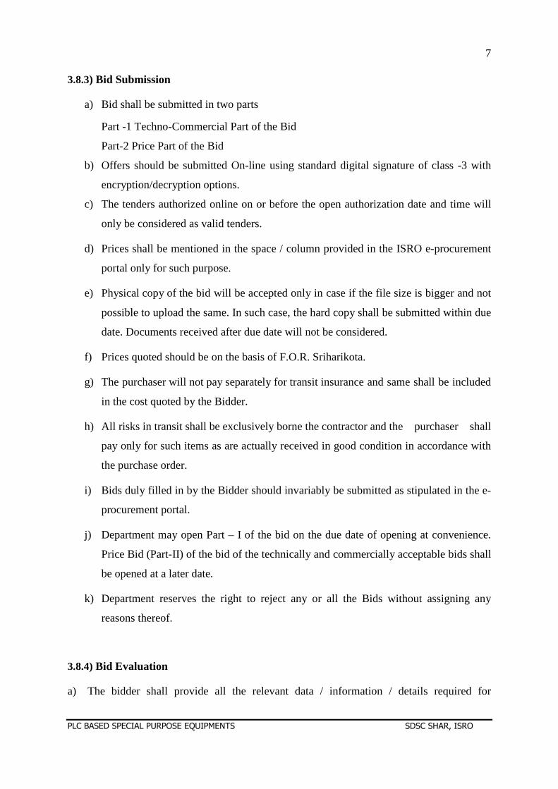
3.8.3) Bid Submission
a) Bid shall be submitted in two parts
Part -1 Techno-Commercial Part of the Bid
Part-2 Price Part of the Bid
b) Offers should be submitted On-line using standard digital signature of class -3 with
encryption/decryption options.
c) The tenders authorized online on or before the open authorization date and time will
only be considered as valid tenders.
d) Prices shall be mentioned in the space / column provided in the ISRO e-procurement
portal only for such purpose.
e) Physical copy of the bid will be accepted only in case if the file size is bigger and not
possible to upload the same. In such case, the hard copy shall be submitted within due
date. Documents received after due date will not be considered.
f) Prices quoted should be on the basis of F.O.R. Sriharikota.
g) The purchaser will not pay separately for transit insurance and same shall be included
in the cost quoted by the Bidder.
h) All risks in transit shall be exclusively borne the contractor and the purchaser shall
pay only for such items as are actually received in good condition in accordance with
the purchase order.
i) Bids duly filled in by the Bidder should invariably be submitted as stipulated in the e-
procurement portal.
j) Department may open Part – I of the bid on the due date of opening at convenience.
Price Bid (Part-II) of the bid of the technically and commercially acceptable bids shall
be opened at a later date.
k) Department reserves the right to reject any or all the Bids without assigning any
reasons thereof.
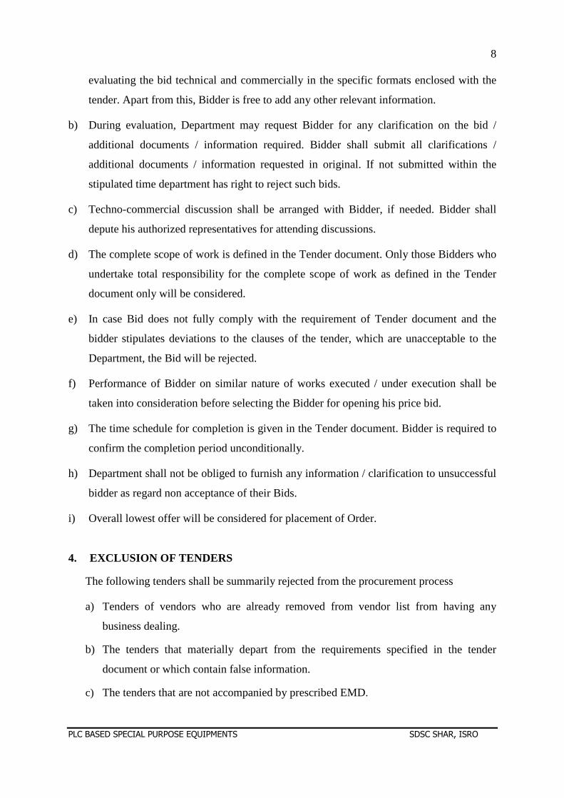
3.8.4) Bid Evaluation
a) The bidder shall provide all the relevant data / information / details required for
8
PLC BASED SPECIAL PURPOSE EQUIPMENTS SDSC SHAR, ISRO
evaluating the bid technical and commercially in the specific formats enclosed with the
tender. Apart from this, Bidder is free to add any other relevant information.
b) During evaluation, Department may request Bidder for any clarification on the bid /
additional documents / information required. Bidder shall submit all clarifications /
additional documents / information requested in original. If not submitted within the
stipulated time department has right to reject such bids.
c) Techno-commercial discussion shall be arranged with Bidder, if needed. Bidder shall
depute his authorized representatives for attending discussions.
d) The complete scope of work is defined in the Tender document. Only those Bidders who
undertake total responsibility for the complete scope of work as defined in the Tender
document only will be considered.
e) In case Bid does not fully comply with the requirement of Tender document and the
bidder stipulates deviations to the clauses of the tender, which are unacceptable to the
Department, the Bid will be rejected.
f) Performance of Bidder on similar nature of works executed / under execution shall be
taken into consideration before selecting the Bidder for opening his price bid.
g) The time schedule for completion is given in the Tender document. Bidder is required to
confirm the completion period unconditionally.
h) Department shall not be obliged to furnish any information / clarification to unsuccessful
bidder as regard non acceptance of their Bids.
i) Overall lowest offer will be considered for placement of Order.
4. EXCLUSION OF TENDERS
The following tenders shall be summarily rejected from the procurement process
a) Tenders of vendors who are already removed from vendor list from having any
business dealing.
b) The tenders that materially depart from the requirements specified in the tender
document or which contain false information.
c) The tenders that are not accompanied by prescribed EMD.
9
PLC BASED SPECIAL PURPOSE EQUIPMENTS SDSC SHAR, ISRO
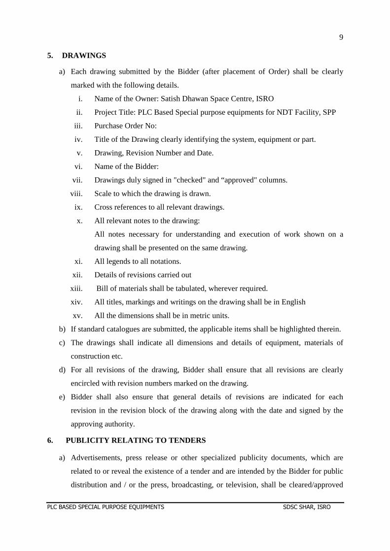
5. DRAWINGS
a) Each drawing submitted by the Bidder (after placement of Order) shall be clearly
marked with the following details.
i. Name of the Owner: Satish Dhawan Space Centre, ISRO
ii. Project Title: PLC Based Special purpose equipments for NDT Facility, SPP
iii. Purchase Order No:
iv. Title of the Drawing clearly identifying the system, equipment or part.
v. Drawing, Revision Number and Date.
vi. Name of the Bidder:
vii. Drawings duly signed in "checked" and “approved" columns.
viii. Scale to which the drawing is drawn.
ix. Cross references to all relevant drawings.
x. All relevant notes to the drawing:
All notes necessary for understanding and execution of work shown on a
drawing shall be presented on the same drawing.
xi. All legends to all notations.
xii. Details of revisions carried out
xiii. Bill of materials shall be tabulated, wherever required.
xiv. All titles, markings and writings on the drawing shall be in English
xv. All the dimensions shall be in metric units.
b) If standard catalogues are submitted, the applicable items shall be highlighted therein.
c) The drawings shall indicate all dimensions and details of equipment, materials of
construction etc.
d) For all revisions of the drawing, Bidder shall ensure that all revisions are clearly
encircled with revision numbers marked on the drawing.
e) Bidder shall also ensure that general details of revisions are indicated for each
revision in the revision block of the drawing along with the date and signed by the
approving authority.
6. PUBLICITY RELATING TO TENDERS
a) Advertisements, press release or other specialized publicity documents, which are
related to or reveal the existence of a tender and are intended by the Bidder for public
distribution and / or the press, broadcasting, or television, shall be cleared/approved
10
PLC BASED SPECIAL PURPOSE EQUIPMENTS SDSC SHAR, ISRO
by the Department.
b) The Department may direct the Bidder to withhold such publicity or to require
modifications to the publicity material. The Bidder shall comply with such direction.
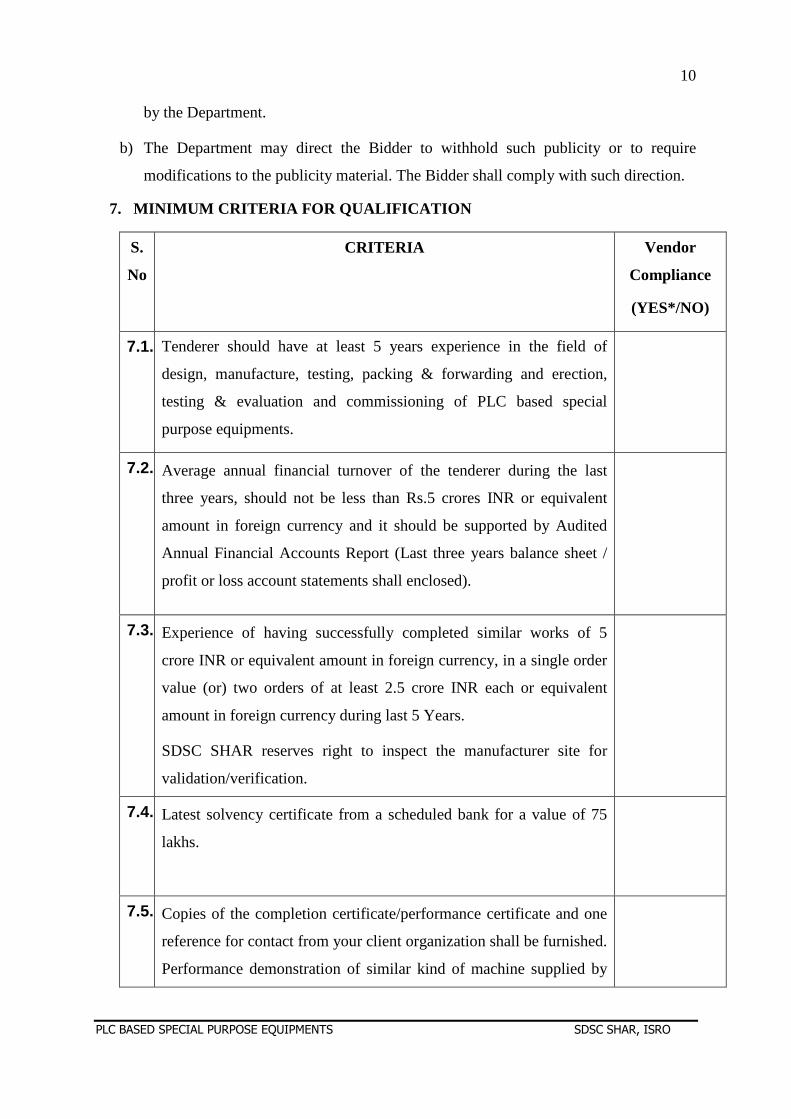
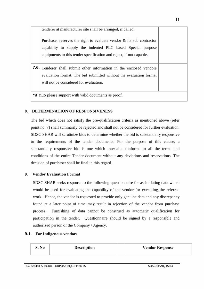
7. MINIMUM CRITERIA FOR QUALIFICATION
S.
No
CRITERIA Vendor
Compliance
(YES*/NO)
7.1. Tenderer should have at least 5 years experience in the field of
design, manufacture, testing, packing & forwarding and erection,
testing & evaluation and commissioning of PLC based special
purpose equipments.
7.2. Average annual financial turnover of the tenderer during the last
three years, should not be less than Rs.5 crores INR or equivalent
amount in foreign currency and it should be supported by Audited
Annual Financial Accounts Report (Last three years balance sheet /
profit or loss account statements shall enclosed).
7.3. Experience of having successfully completed similar works of 5
crore INR or equivalent amount in foreign currency, in a single order
value (or) two orders of at least 2.5 crore INR each or equivalent
amount in foreign currency during last 5 Years.
SDSC SHAR reserves right to inspect the manufacturer site for
validation/verification.
7.4. Latest solvency certificate from a scheduled bank for a value of 75
lakhs.
7.5. Copies of the completion certificate/performance certificate and one
reference for contact from your client organization shall be furnished.
Performance demonstration of similar kind of machine supplied by
11
PLC BASED SPECIAL PURPOSE EQUIPMENTS SDSC SHAR, ISRO
tenderer at manufacturer site shall be arranged, if called.
Purchaser reserves the right to evaluate vendor & its sub contractor
capability to supply the indented PLC based Special purpose
equipments to this tender specification and reject, if not capable.
7.6. Tenderer shall submit other information in the enclosed vendors
evaluation format. The bid submitted without the evaluation format
will not be considered for evaluation.
* if YES please support with valid documents as proof.
8. DETERMINATION OF RESPONSIVENESS
The bid which does not satisfy the pre-qualification criteria as mentioned above (refer
point no. 7) shall summarily be rejected and shall not be considered for further evaluation.
SDSC SHAR will scrutinize bids to determine whether the bid is substantially responsive
to the requirements of the tender documents. For the purpose of this clause, a
substantially responsive bid is one which inter-alia conforms to all the terms and
conditions of the entire Tender document without any deviations and reservations. The
decision of purchaser shall be final in this regard.
9. Vendor Evaluation Format
SDSC SHAR seeks response to the following questionnaire for assimilating data which
would be used for evaluating the capability of the vendor for executing the referred
work. Hence, the vendor is requested to provide only genuine data and any discrepancy
found at a later point of time may result in rejection of the vendor from purchase
process. Furnishing of data cannot be construed as automatic qualification for
participation in the tender. Questionnaire should be signed by a responsible and
authorized person of the Company / Agency.
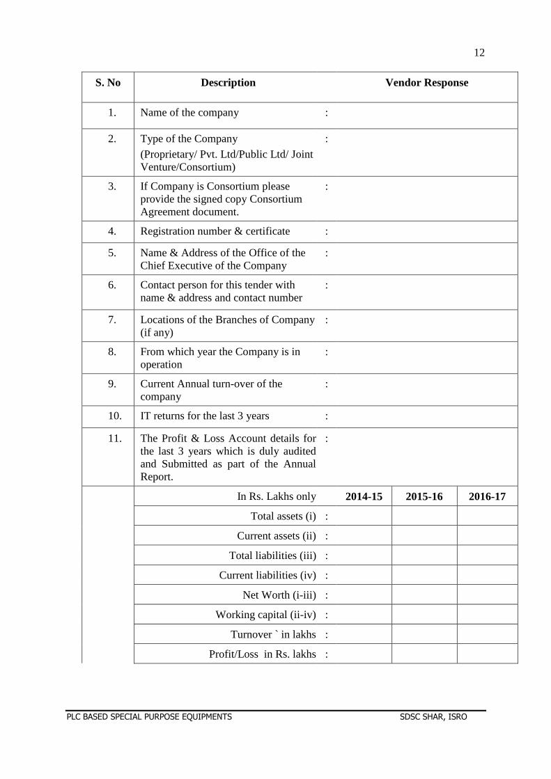
9.1. For Indigenous vendors
S. No Description Vendor Response
12
PLC BASED SPECIAL PURPOSE EQUIPMENTS SDSC SHAR, ISRO
S. No Description Vendor Response
1. Name of the company :
2. Type of the Company
(Proprietary/ Pvt. Ltd/Public Ltd/ Joint Venture/Consortium)
:
3. If Company is Consortium please provide the signed copy Consortium Agreement document.
:
4. Registration number & certificate :
5. Name & Address of the Office of the Chief Executive of the Company
:
6. Contact person for this tender with name & address and contact number
:
7. Locations of the Branches of Company (if any)
:
8. From which year the Company is in operation
:
9. Current Annual turn-over of the company
:
10. IT returns for the last 3 years :
11. The Profit & Loss Account details for the last 3 years which is duly audited and Submitted as part of the Annual Report.
:
In Rs. Lakhs only 2014-15 2015-16 2016-17
Total assets (i) :
Current assets (ii) :
Total liabilities (iii) :
Current liabilities (iv) :
Net Worth (i-iii) :
Working capital (ii-iv) :
Turnover ` in lakhs :
Profit/Loss in Rs. lakhs :
13
PLC BASED SPECIAL PURPOSE EQUIPMENTS SDSC SHAR, ISRO
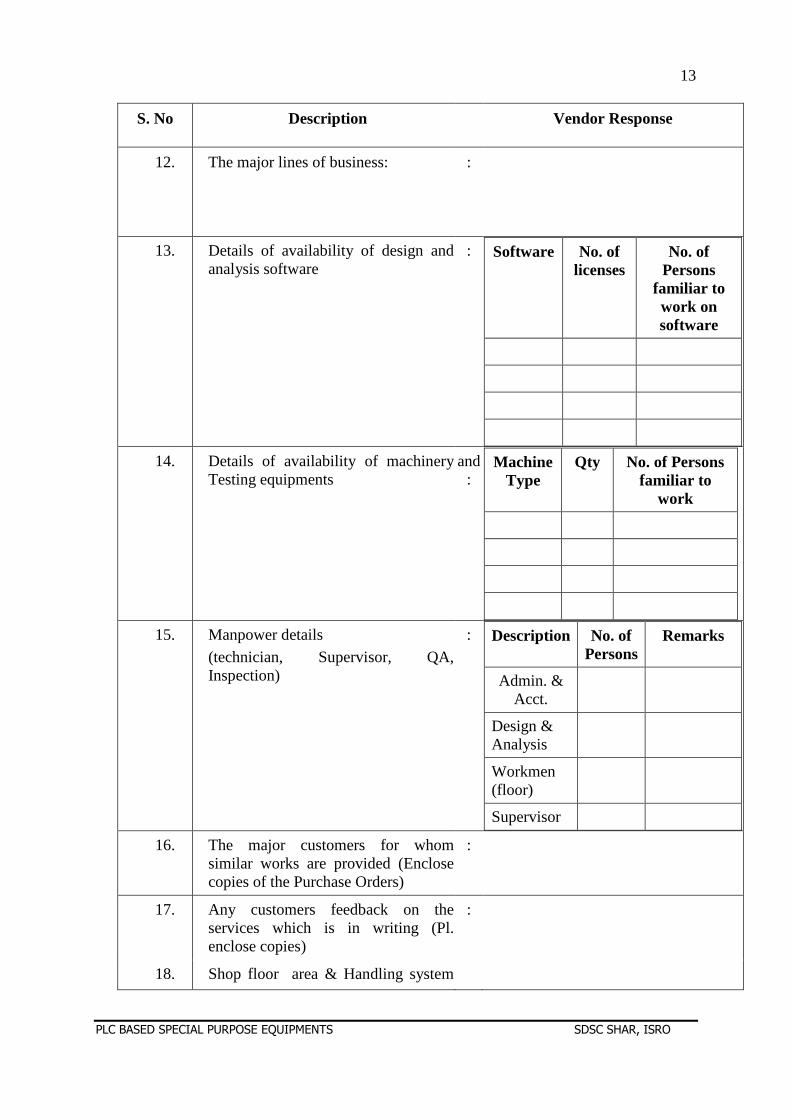
S. No Description Vendor Response
12. The major lines of business: :
13. Details of availability of design and analysis software
: Software No. of licenses
No. of Persons
familiar to work on software
14. Details of availability of machinery Testing equipments
and :
Machine Type
Qty No. of Persons familiar to
work
15. Manpower details
(technician, Supervisor, QA, Inspection)
: Description No. of Persons
Remarks
Admin. & Acct.
Design & Analysis
Workmen (floor)
Supervisor
16. The major customers for whom similar works are provided (Enclose copies of the Purchase Orders)
:
17. Any customers feedback on the services which is in writing (Pl. enclose copies)
:
18. Shop floor area & Handling system
14
PLC BASED SPECIAL PURPOSE EQUIPMENTS SDSC SHAR, ISRO
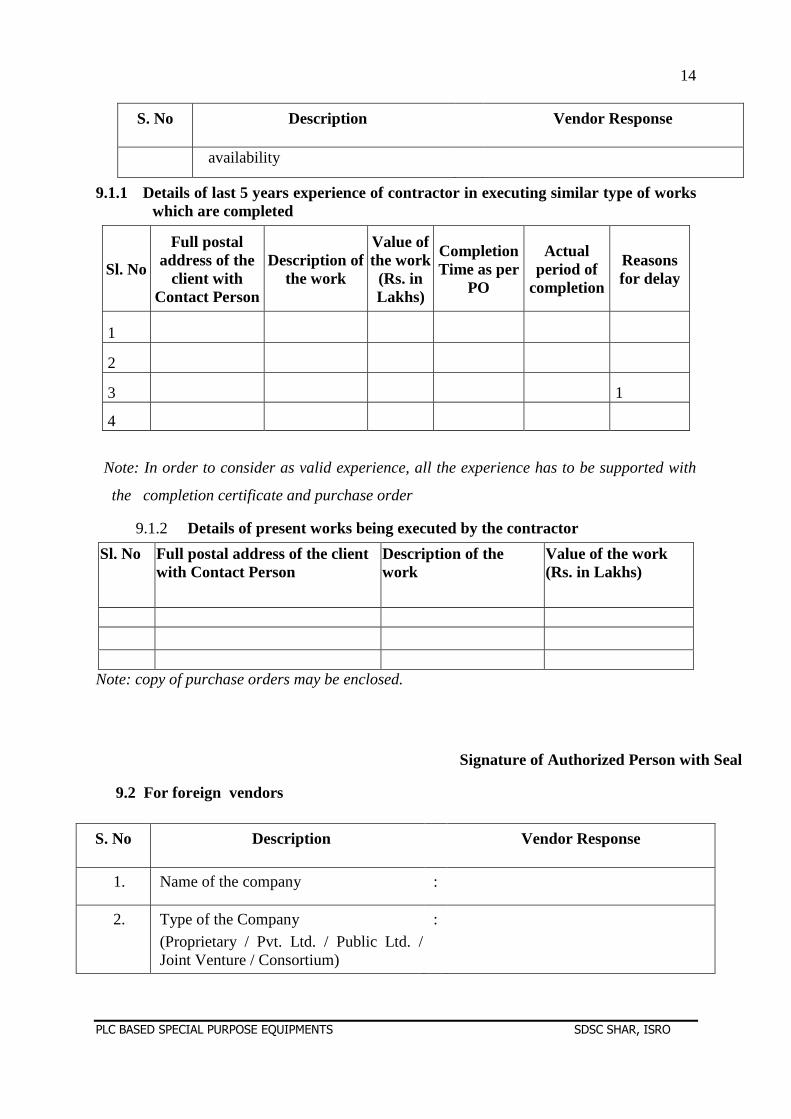
S. No Description Vendor Response
availability
9.1.1 Details of last 5 years experience of contractor in executing similar type of works which are completed
Sl. No
Full postal address of the
client with Contact Person
Description of the work
Value of the work (Rs. in Lakhs)
Completion Time as per
PO
Actual period of
completion
Reasons for delay
1
2
3 1
4
Note: In order to consider as valid experience, all the experience has to be supported with
the completion certificate and purchase order
9.1.2 Details of present works being executed by the contractor
Sl. No Full postal address of the client with Contact Person
Description of the work
Value of the work (Rs. in Lakhs)
Note: copy of purchase orders may be enclosed.
Signature of Authorized Person with Seal
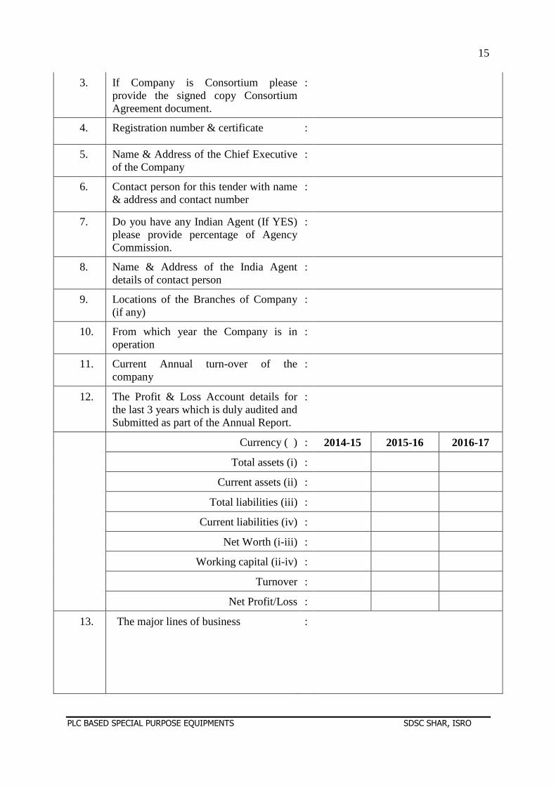
9.2 For foreign vendors
S. No Description Vendor Response
1. Name of the company :
2. Type of the Company
(Proprietary / Pvt. Ltd. / Public Ltd. / Joint Venture / Consortium)
:
15
PLC BASED SPECIAL PURPOSE EQUIPMENTS SDSC SHAR, ISRO
3. If Company is Consortium please provide the signed copy Consortium Agreement document.
:
4. Registration number & certificate :
5. Name & Address of the Chief Executive of the Company
:
6. Contact person for this tender with name & address and contact number
:
7. Do you have any Indian Agent (If YES) please provide percentage of Agency Commission.
:
8. Name & Address of the India Agent details of contact person
:
9. Locations of the Branches of Company (if any)
:
10. From which year the Company is in operation
:
11. Current Annual turn-over of the company
:
12. The Profit & Loss Account details for the last 3 years which is duly audited and Submitted as part of the Annual Report.
:
Currency ( ) : 2014-15 2015-16 2016-17
Total assets (i) :
Current assets (ii) :
Total liabilities (iii) :
Current liabilities (iv) :
Net Worth (i-iii) :
Working capital (ii-iv) :
Turnover :
Net Profit/Loss :
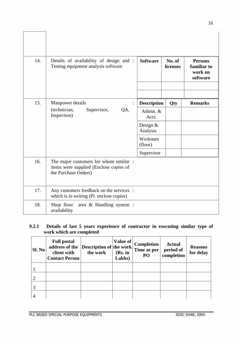
13. The major lines of business :
16
PLC BASED SPECIAL PURPOSE EQUIPMENTS SDSC SHAR, ISRO
9.2.1 Details of last 5 years experience of contractor in executing similar type of work which are completed
Sl. No
Full postal address of the
client with Contact Person
Description of the work
Value of the work (Rs. in Lakhs)
Completion Time as per
PO
Actual period of
completion
Reasons for delay
1
2
3
4
14. Details of availability of design and Testing equipment analysis software
: Software No. of licenses
Persons familiar to work on software
15. Manpower details
(technician, Supervisor, QA, Inspection)
: Description Qty Remarks
Admin. & Acct.
Design & Analysis
Workmen (floor)
Supervisor
16. The major customers for whom similar items were supplied (Enclose copies of the Purchase Orders)
:
17. Any customers feedback on the services which is in writing (Pl. enclose copies)
:
18. Shop floor area & Handling system availability
:
17
PLC BASED SPECIAL PURPOSE EQUIPMENTS SDSC SHAR, ISRO
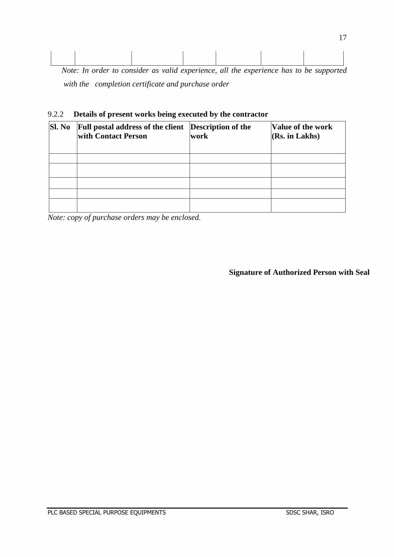
Note: In order to consider as valid experience, all the experience has to be supported
with the completion certificate and purchase order
9.2.2 Details of present works being executed by the contractor
Sl. No Full postal address of the client with Contact Person
Description of the work
Value of the work (Rs. in Lakhs)
Note: copy of purchase orders may be enclosed.
Signature of Authorized Person with Seal

18
PLC BASED SPECIAL PURPOSE EQUIPMENTS SDSC SHAR, ISRO
SECTION -A
GENERAL TERMS AND CONDITIONS OF CONTRACT
19
PLC BASED SPECIAL PURPOSE EQUIPMENTS SDSC SHAR, ISRO
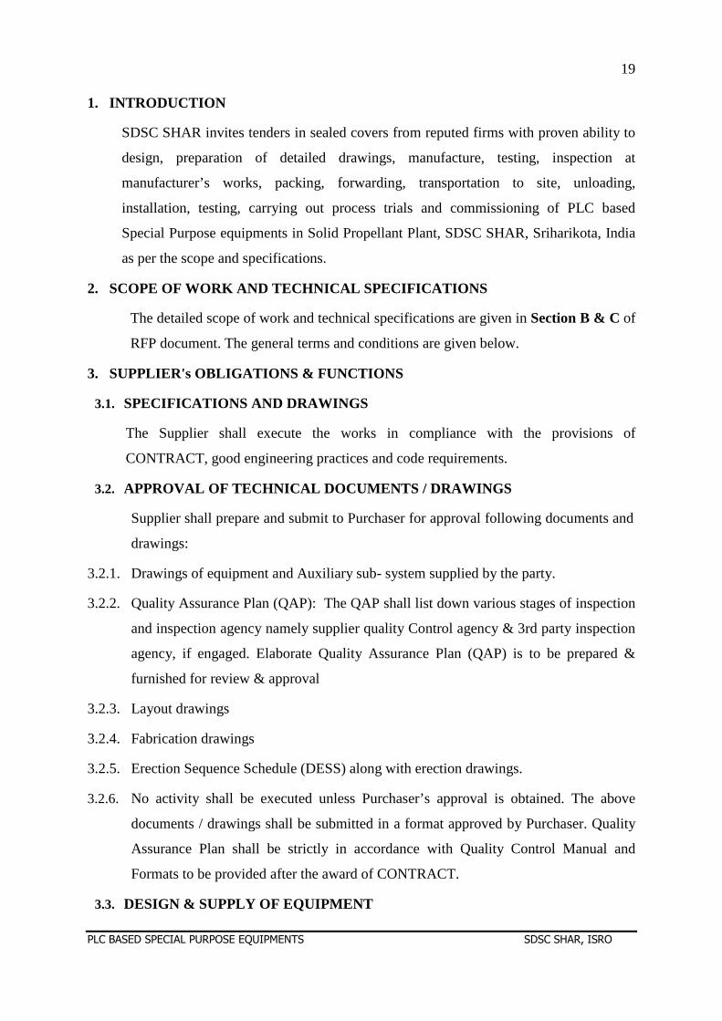
1. INTRODUCTION
SDSC SHAR invites tenders in sealed covers from reputed firms with proven ability to
design, preparation of detailed drawings, manufacture, testing, inspection at
manufacturer’s works, packing, forwarding, transportation to site, unloading,
installation, testing, carrying out process trials and commissioning of PLC based
Special Purpose equipments in Solid Propellant Plant, SDSC SHAR, Sriharikota, India
as per the scope and specifications.
2. SCOPE OF WORK AND TECHNICAL SPECIFICATIONS
The detailed scope of work and technical specifications are given in Section B & C of
RFP document. The general terms and conditions are given below.
3. SUPPLIER's OBLIGATIONS & FUNCTIONS
3.1. SPECIFICATIONS AND DRAWINGS
The Supplier shall execute the works in compliance with the provisions of
CONTRACT, good engineering practices and code requirements.
3.2. APPROVAL OF TECHNICAL DOCUMENTS / DRAWINGS
Supplier shall prepare and submit to Purchaser for approval following documents and
drawings:
3.2.1. Drawings of equipment and Auxiliary sub- system supplied by the party.
3.2.2. Quality Assurance Plan (QAP): The QAP shall list down various stages of inspection
and inspection agency namely supplier quality Control agency & 3rd party inspection
agency, if engaged. Elaborate Quality Assurance Plan (QAP) is to be prepared &
furnished for review & approval
3.2.3. Layout drawings
3.2.4. Fabrication drawings
3.2.5. Erection Sequence Schedule (DESS) along with erection drawings.
3.2.6. No activity shall be executed unless Purchaser’s approval is obtained. The above
documents / drawings shall be submitted in a format approved by Purchaser. Quality
Assurance Plan shall be strictly in accordance with Quality Control Manual and
Formats to be provided after the award of CONTRACT.
3.3. DESIGN & SUPPLY OF EQUIPMENT
20
PLC BASED SPECIAL PURPOSE EQUIPMENTS SDSC SHAR, ISRO
3.3.1. The supplier shall provide overall general arrangement of the machine with all major
dimensions.
3.3.2. The details / designs and GA drawings given in the tender for various systems /
equipments are of minimum requirement and are for guidance only. Contractor is free
to modify / improve / redress the design if required to meet the guaranteed
performance of the systems / equipments being supplied. Design and fabrication
drawings of the machine tool and auxiliary systems shall be prepared and sent by the
Bidder for scrutiny /review/clearance by Purchaser. The Bidder shall incorporate
necessary changes/revisions in the design based on the suggestions made by the
Purchaser or its authorized representatives and shall submit the drawings for clearance
prior to undertaking fabrication/manufacturing. Scrutiny /review/clearance of the
drawings by SDSC, SHAR shall not absolve the responsibility of the Bidder from
proper performance of the machine and from the guarantee/warranty clauses.
However any modification / improvement shall be carried out after approval by the
Purchaser.
3.3.3. Supplier shall carry out detailed engineering, manufacture / procure and supply the
equipment in accordance with the scope, technical specifications and terms &
conditions of contract.
3.3.4. Any item which may not have been specifically mentioned herein but are needed to
complete the equipment / system shall also be treated as included and the same shall
also be supplied and erected at no extra cost, unless otherwise specifically excluded as
indicated.
3.3.5. Supply of bought out items shall be as mentioned in the technical bid.
3.3.6. All these goods or material shall be supplied or used shall be new and of first quality.
Where imported or partly imported goods or material are offered or intended to be
used, the fact must be specifically stated and brought to the notice of Purchaser.
3.4. INSPECTION AND TESTING
3.4.1 The supplier shall identify various stages of inspection and quality control of the
system including sub systems, components and bought out items etc., and inform the
same to SDSC, SHAR in advance. The approved QAP shall be followed during course
of Manufacture, Erection & Testing.
21
PLC BASED SPECIAL PURPOSE EQUIPMENTS SDSC SHAR, ISRO
3.4.2 Purchaser reserves the right to inspect all phases of Supplier’s operations through its
representatives and/or third party inspection agency approved by the Purchaser.
Therefore it is the responsibility of the supplier to provide the necessary support for the
inspection agency and get the works inspected at all stages of work as identified in
quality assurance plan. The presence or absence of a Purchaser’s representative does
not relieve the Supplier of the responsibility for quality control in all phases of the
work. In the event that any of the work being done by the Supplier or any Sub-
Supplier is found by Purchaser’s representatives to be unsatisfactory or not in
accordance with the drawings, procedures, specifications, and standards the Supplier
shall, upon verbal notice of such discrepancy or deficiency, take immediate steps to
revise the work in a manner to conform to the relevant drawings, procedures and
specifications. The Supplier shall carry out required supervision and inspection as per
Quality Assurance Plan and furnish all assistance required by the Purchaser in carrying
out inspection work during this phase.
3.4.3 The authorized inspectors of the purchaser shall have access to the premises of the
supplier and its sub-contractors at all reasonable times. All the equipments,
instruments, tools that are necessary for the inspection shall be provided by the
supplier on demand by purchaser’s own inspectors or a third party authorized by
purchaser. Inspection by purchaser’s own inspectors or by third party authorized by
purchaser shall not absolve the responsibility of the supplier from proper performance
of the machine and from the guarantee/warranty clauses stipulated in the contract.
3.5. DELIVERY AND STORAGE
3.5.1 Dispatch Instructions given in the Contract shall be strictly followed. Failure to
comply with the instructions may result in delay in payment apart from imposing any
other charges as may be deemed to fit.
3.5.2 The Supplier shall be responsible for transporting all the equipment to site, unloading
and storage. No equipment shall be delivered without obtaining dispatch clearance
from Purchaser. All the equipment shall be properly packed to avoid any damage
during transportation / handling / storage.
3.5.3 Party shall undertake the responsibility of the machine and its components during
transportation to Sriharikota and during erection, testing and commissioning of the
22
PLC BASED SPECIAL PURPOSE EQUIPMENTS SDSC SHAR, ISRO
same at suitable location identified by SDSC, SHAR and until handing over the
machine to SDSC, SHAR after its acceptance. SDSC, SHAR will provide sheltered
area for storage of the machine and its components. Supplier shall take proper care
while storing the equipment and shall provide watch and ward at his own cost.
3.5.4 First fill of hydraulic oil, lubricating oil, coolant oil & other consumables as required
are to be provided in seal packed at purchaser site.
4. INSTALLATION
4.1. GENERAL
4.1.1 Supplier’s staff shall include adequate number of competent erection engineers with
proven experience on similar works to supervise the erection works and sufficient
skilled, unskilled and semi-skilled labour to ensure completion of work in time.
4.1.2 Supplier's erection staff shall arrive at site on date agreed by Purchaser. Prior to
proceeding to work, Supplier shall however, first ensure that required/sufficient part
of his supply has arrived at site.
4.1.3 EOT crane will be made available by purchaser in the building where Crane based
handling system is to be installed. This EOT crane may be used for installation work.
4.1.4 60 t capacity EOT Crane, Material handling equipments viz. 3, 5 & 12 ton Forklift, 15
& 12 ton hydra systems, 300 kg capacity scissor lift, 1 ton capacity pallet truck etc.
available with purchaser will be provided free of cost subjected to availability &
approval.
4.1.5 Special equipments / Material handling equipments other than above mentioned
equipments required for erection work shall be arranged by the supplier.
4.1.6 Piping / cable trench / embedded plate etc. required in the building shall be made
available by purchaser.
4.1.7 Purchaser will make ready the machine foundation, trenches and provision of water
supply to a place identified near the building as per the details furnished by the party.
4.1.8 Erection of equipment may be phased in such a manner so as not to obstruct the work
being done by Other Suppliers and / or operating staff that may be present at that
time.
23
PLC BASED SPECIAL PURPOSE EQUIPMENTS SDSC SHAR, ISRO
4.1.9 During erection, Purchaser's engineer will visit site from time to time with or without
Supplier’s engineer to establish conformity of the work with specification. Any
deviations, deficiencies or evidence of unsatisfactory workmanship shall be corrected
as instructed by Purchaser.
4.1.10 Tank, pipe flushing / purging is in supplier scope.
4.1.11 Supplier shall carry out work in a true professional manner and strictly adhere to the
approved drawings. Any damage caused by Supplier during erection to new or
existing building shall be made good at no extra cost to Purchaser.
4.2. SETTING OUT, LEVELLING AND GROUTING OF EQUIPMENT
4.2.1 Supplier shall check the civil works where the equipment is to be erected in advance
for their correctness / conformity to the approved drawings for erection of equipment
with respect to their lines, levels, pockets, openings, cut outs etc. and shall notify
Purchaser of any major deviation.
4.2.2 Supplier shall mark precisely the centre lines and datum reference on civil works
where the equipment is to be erected with reference to benchmark given by Civil
Supplier. Any minor adjustment necessary to structure (on which equipment is to be
erected) for making them plumb and level shall be carried out by Supplier at his cost.
4.2.3 All the grout for equipment shall be carried out using non-shrinkable grout. Surfaces
receiving grout shall be prepared to receive grout. All block outs for pipes (puddle
pipes), sleeves etc. shall be grouted by using cement concrete of the same grade as
that of the parent structure. All associated civil works such as cutting of re-bar,
chipping or dressing of foundation or widening openings in R.C.C. Work and brick
work, drilling holes in concrete work or brick work shall be carried out by Supplier as
part of the scope of contract.
4.3. RECORDS
Supplier shall maintain records pertaining to the quality of erection work in a format
approved by Purchaser. Whenever erection work is complete, Supplier shall offer
erected equipment for inspection to Purchaser's engineer who along with Supplier's
engineer will sign such records on acceptance.
24
PLC BASED SPECIAL PURPOSE EQUIPMENTS SDSC SHAR, ISRO
The complete construction of machine right from component level till the complete
machine assembly performance tested including sub – assembly shall be properly
documented with drawing, raw material, Test certificate etc.
There shall be time to time submission of information /clearance / approval by the
purchaser and all comments shall be duly incorporated.
All such drawing will become part of PRODUCTION MASTER FILE which shall
also contain as built drawing, Final Erection, Testing & Commissioning report done
at site.
3 copies of PRODUCTION MASTER FILE shall be supplied.
4.4. EQUIPMENT ERECTION
4.4.1 Supplier shall carry out the works in accordance with the specific instructions given
on the approved drawings, method statements, manufacturer’s drawings / documents
or as directed by Purchaser. Equipment shall be erected in neat workmen like manner
so that they are level, plumb, and square and properly aligned and oriented.
Tolerances shall be as established in manufactures drawings or as stipulated by
Purchaser. No equipment shall be grouted or bolted down to the foundation, until its
alignment is checked and found acceptable by Purchaser.
4.4.2 Supplier shall provide all supervision, labour, tools, machines, cranes, slings, wire
rope, D-shackle etc., equipments, scaffolding, rigging material and incidental material
such as bolts, wedges, anchors, concrete inserts, grout material etc. required to
complete the works. Supplier shall also provide at his own cost all such consumables
like oxygen - acetylene gas welding rods, grinding wheels, temporary supports, shims
etc. required to complete work.
4.4.3 Supplier shall take utmost care while handling instruments, delicate equipments,
panels etc., and protect all such equipments on erection.
5. DRAWINGS AND O&M MANUALS
5.1. Supplier shall submit 3 hard copies & one soft copy of all the approved drawings
incorporating any modification / changes made during the execution of CONTRACT.
All these drawings shall be marked as 'As Built'.
5.2. Supplier shall submit 6 hard & 1 soft copy of the following documents:
25
PLC BASED SPECIAL PURPOSE EQUIPMENTS SDSC SHAR, ISRO
5.2.1 Operations manual of the machine.
5.2.2 Programs manual.
5.2.3 Maintenance manual with drawings, circuit diagrams, interfacing instructions, trouble
shooting and maintenance instructions and spares list with source of supply.
5.2.4 Lubricating chart with oil /grease type, quantity, changing interval, brand name
should be indicated clearly.
5.2.5 Manuals of PLC based Special purpose equipments from the original equipment
manufacturer (OEM) or supplier.
5.2.6 Control system Documents on DVD
5.3. Submission of the drawings and manuals shall be a precondition for releasing of any
final payment due to Supplier.
6. MAINTENANCE SERVICES
During the post commissioning period for at least 05 Years, supplier has to provide the
following services:
6.1. Maintenance visits on call basis or as required by Purchaser for observing the
performance of Machine.
6.2. Repair charges like replacement of spares.
6.3. The supplier shall undertake to maintain the machine on “Annual maintenance
contract” basis as per mutually agreed terms, which will be entered after expiry of
warranty. Supplier shall quote the Annual Maintenance Contract charge per year for
minimum of 05 years.
6.4. The party shall extend support for all spares for a period of ten years.
7. TRAINING
The supplier shall provide training in the operation, maintenance and trouble shooting of
PLC based Special purpose equipments two departmental personnel free of cost at
purchaser’s site.
8. SCHEDULE OF PRICE
8.1. CONTRACT price shall include all costs of “ design, preparation of detailed drawings,
manufacture, testing, inspection at manufacturer’s works, packing, forwarding,
26
PLC BASED SPECIAL PURPOSE EQUIPMENTS SDSC SHAR, ISRO
transportation to site, unloading, installation, testing, carrying out process trials and
commissioning of PLC based Special Purpose equipments”. Shop floor testing, packing,
forwarding, transport to site, unloading, storage, all risk coverage, erection, installation,
training, testing & evaluation and commissioning of equipment including associated
civil work and any other cost for proper and complete execution of the CONTRACT.
8.2. CONTRACT prices shall also include all travelling expenses, living expenses, salaries,
overtime, benefit and any other compensation for engineers, supervisors, skilled,
semiskilled workmen, watch and ward staff, laborer and other staff employed by the
Supplier, cost of tools and tackles required for erection and other consumable material
required, and all taxes, duties, and levies as applicable on the date of submission of bid.
8.3. Price shall be firm & fixed.
8.4. Supplier shall quote the prices as per the price bid format enclosed as Section-D
Annexure - I
8.5. The rate quoted shall be on DDP / DAP SDSC SHAR, Sriharikota basis.
8.6. All rates of taxes/duties/levies applicable with details of percentage and applicable
portion of the price should be spelt out clearly in the offer.
8.7. The taxes applicable for supply and erection & commissioning shall be indicated
separately in terms of percentage in the price bid. If the offers submitted by the
suppliers are silent on taxes, it will be presumed that quoted rates are inclusive of taxes
& duties and no claim in this regard will be entertained later.
8.8. Purchaser is eligible for exemption of Customs Duty for imported items and Excise
Duty for indigenous items. Necessary exemption certificate will be provided to the
suppliers against request. This may be taken into account while quoting for items.
8.9. In order to take care of the currency fluctuations, Tenderers are requested / suggested to
quote imported items in the currency from where it is being imported. If the tenderer
quotes imported items in INR (Indian Rupees) future claim on currency fluctuation shall
not be considered.
8.10. In case of foreign suppliers the prices shall be quoted on DDP / DAP, SRIHARIKOTA
basis. In case of any change, supplier shall identify the Indian agent and responsibilities
related to clearing the consignment, transport of equipment to destination and erection &
commissioning at site and all the necessary works till the equipment is commissioned
27
PLC BASED SPECIAL PURPOSE EQUIPMENTS SDSC SHAR, ISRO
and accepted by Purchaser as per the mutually agreed acceptance plan in the contract
document.
9. DISCOUNTS
Supplier shall not indicate any discount separately and quoted price should be after
deducting the discount.
10. MODE OF PAYMENT
10.1. In case of indigenous suppliers, all the payments due to Supplier shall be made in Indian
currency by crossed “Account Payee” cheque sent to the registered office of the
Supplier. Supplier can submit the banker details and payments can also be made through
Electronic Clearance System (ECS).
10.2. In case foreign suppliers LC will be established for supply portion and erection &
commissioning portion separately. The agency commission shall be paid in Indian
Rupee based on the supplier’s authorization. Any other mode of payment shall be
stipulated by the tenderer clearly in the deviation statement attached in section-D
Annexure - II of the proposal document.
11. TERMS OF PAYMENTS
a) 20% as advance against Bank guarantee and invoice if required.
b) 70% on receipt of items and on inspection by CLIP at our site
c) 10% within 30 days from the date of commissioning and final acceptance.
d) Wherever advance payment is requested, Bank Guarantee from any Nationalized
Bank/Scheduled Bank should be furnished. In case of advance payments, if the party is
not supplying the material within the delivery schedule, interest will be levied as per the
Bank Lending Rate plus 2% penal interest.
e) Interest will be loaded for advance payments/stage payments as per the lending rate of
Bank and will be added to the landed cost for comparison purpose. In case of different
milestone payments submitted by the parties, a standard and transparent methodology like
NPV will be adopted for evaluating the offers.
12. DELIVERY SCHEDULE
a) The PLC based Special Purpose Equipments shall be commissioned at SDSC SHAR
within eleven months from the date of receipt of purchase order.
28
PLC BASED SPECIAL PURPOSE EQUIPMENTS SDSC SHAR, ISRO
b) Delivery date is essence for this contract. Party shall adhere to the delivery date
mentioned in this tender and same shall be confirmed along with the offer. In case Party
is unable to meet the delivery schedule, the offer is liable for rejection.
c) Intermediate milestones as identified mutually after placement of order shall be met
with.
13. LIQUIDATED DAMAGES
In the event of the Supplier failing to complete the work within the delivery period
specified in the contract agreement or any extension agreed thereto, the Purchaser shall
reserve the right to recover from the Supplier as liquidated damages, a sum of 0.5
percentage per week or part thereof of the undelivered portion of the total contract price
of equipment or work. The Total liquidated damages shall not exceed the 10.0 percentage
of the total Contract price.
14. EXTENSION OF TIME
14.1. If the completion of deliveries of equipment, work is delayed due to reason of Force
Majeure the Supplier shall without delay give notice to the Purchaser in writing of their
claim for an extension of time. The Purchaser on receipt of such notice may agree to
extend the Contract period or delivery date as may be reasonable but without prejudice
to other terms and conditions of the Contract.
14.2. Both parties shall keep a record of the circumstances referred to above which are
responsible for causing delays in the execution of the services and shall give notice to
the other party of any such cause as soon as it occurs. An event of Force Majeure, where
so ever it occurs, provided it affects either party in fulfilling its obligations under this
contract, shall justify the affected party's claim of Force Majeure. Should one or both the
parties be prevented from fulfilling their contractual obligations by a state of Force
Majeure lasting continuously for more than a month, the parties shall consult with each
other regarding the future execution of the contract.
15. FOREIGN EXCHANGE OUTGO AND VARIATION
15.1. Supplier shall indicate the Foreign exchange component considered in their offer. The
foreign exchange component shall be included in the lumpsum price quoted / unit rates
quoted. The foreign exchange component shall be limited to the amount indicated.
29
PLC BASED SPECIAL PURPOSE EQUIPMENTS SDSC SHAR, ISRO
15.2. For variation in foreign exchange rate for currency other than those indicated, the Base
Exchange rate for such currency prevailing on the date of price bid / revised offer which
ever is later subject to documentary evidence shall be considered.
16. TAXES AND DUTIES
16.1. GST
The applicable rate of GST (CGST/SGST/IGST/UGST) shall be clearly mentioned
along with the concerned HSN code / SAC.
As per the notification number 47/2017-Integrated Tax (Rate) dated 14-11-2017, issued
by the government of India, Ministry of Finance, Department of Revenue, we are
eligible for IGST of 5 %. Exemption certificate as required under the said notification
will be provided along with the purchase order.
16.2. CUSTOMS DUTY
a) The Purchaser is eligible for Customs Duty exemption as per Notification No.05/2018
dated 25-01-2018. This may be taken into account while quoting for import items.
b) In case tender offering items considering the customs duty exemption, they shall also
indicate the price, separately, with customs duty component and terms and conditions
thereto.
16.3. INCOME TAX
Income tax at the prevailing rate as applicable and if applicable from time to time
shall be deducted from the supplier's bills as per Income Tax Act and a certificate
issued (TDS Certificate).
16.4. EARNEST MONEY DEPOSIT (EMD)
a) Party shall submit EMD of Rs. 5.0 Lakh. EMD shall be submitted in a single
installment through Demand Draft / Banker’s Cheque / Fixed Deposit Receipts or
Bank Guarantee from any of the Scheduled Banks executed on non-judicial stamp
paper of appropriate value.
b) Central PSUs / PSEs / Autonomous Bodies, Micro and Small Enterprises, KVIC,
National Small Industries Corporation, etc., will be exempted from the payment of
EMD.
30
PLC BASED SPECIAL PURPOSE EQUIPMENTS SDSC SHAR, ISRO
c) Parties who are registered (registered and empanelled) with Satish Dhawan Space
Centre e-procurement portal are also exempted from the payment of EMD.
d) In case of bank guarantee, it shall be valid for a period of 45 days beyond the final
tender validity date.
e) Any tender not accompanied with EMD shall be treated as invalid tender and rejected.
Vendors seeking exemption from payment of EMD shall submit necessary proof like
registration number, etc.
f) EMD of a vendor shall be forfeited if the vendor withdraws or amends his tender or
deviates from the tender in any respect within the period of validity of the tender.
g) Failure to furnish security deposit/performance bond by a successful vendor within
the specified period shall also result in forfeiture of EMD.
h) EMD shall be refunded to all the unsuccessful vendors within thirty days after
placement of the Purchase Order.
i) EMD shall be refunded to the successful vendor after payment of the Security Deposit
or may be adjusted against the Security Deposit.
j) EMD shall be refunded to all the participants in cases where the tender is cancelled or
withdrawn by the Centre/Unit, within thirty days from the date of such cancellation or
withdrawal.
17. RISK COVERAGE
The Supplier shall arrange comprehensive risk coverage at his own cost covering the
value of equipment including transportation to the site from manufacturer’s works,
storage at site, fabrication, erection, testing and commissioning at site. The period of
such coverage shall be up to contractual completion period or any extension granted
by Purchaser thereof.
18. SECURITY DEPOSIT
a) Party shall submit security deposit, within 15 days from the date of order placement,
for 10% of the total order value. Security Deposit shall be obtained through Bank
Guarantee or fixed deposit receipt from any of the Scheduled Banks executed on non-
judicial stamp paper of appropriate value, and shall be valid for a period of sixty days
beyond the date for completion of the Purchase Order.
31
PLC BASED SPECIAL PURPOSE EQUIPMENTS SDSC SHAR, ISRO
b) In case the vendor fails to furnish the security deposit within the specified date or
extended due date, the Purchase Order/Contract shall be cancelled, and the EMD, if
any, made earlier shall be forfeited, and, in addition, appropriate penal action will be
considered.
c) Central PSUs / PSEs / Autonomous Bodies / MSEs shall be exempted from the
payment of Security Deposit, and instead, an Indemnity Bond shall be submitted by
them in lieu of the Security Deposit.
19. PACKING AND FORWARDING
a) The tenderer will be held responsible for the stores being sufficiently and properly
packed for transport by rail, road, sea or air, to withstand transit hazards and ensure
safe arrival at the destination.
b) The packing and Marking of packages shall be done by and at the expenses of the
Contractor.
20. WARRANTY
The supplier shall provide twelve months warranty for the entire system for a defect
liability, after final official handing over at his cost. During this period supplier has to
provide and adhere to the following:
20.1. This period shall include maintenance, replacement of defective / failed parts at free of
cost.
20.2. Supplier has to attend unlimited breakdown calls.
20.3. Purchaser will not provide any transport/accommodation for this purpose.
20.4. Upon oral or written notification of defects in or malfunctioning of the goods during
the warranty period which require corrective action, Supplier shall send the necessary
personnel to job site to supervise and assume responsibility for repairs and/or
replacement, if necessary, of the defective goods or material at his own cost. If
Supplier does not, within seven (7) days after receipt of notification, take steps to
correct the breach, Purchaser may do so at the cost and expense of Supplier. Supplier
shall reimburse Purchaser all expenses incurred by Purchaser to repair or replace
malfunctioning or non-conforming goods.
32
PLC BASED SPECIAL PURPOSE EQUIPMENTS SDSC SHAR, ISRO
20.5. Purchaser has no obligation to discover defects, patent or otherwise, and this shall be
sole responsibility of Supplier. Inspection and clearance for shipment by Purchaser’s
inspectors or Inspection agency appointed by Purchaser shall not relieve Supplier of
any of his obligation and duties under the terms and conditions herein.
20.6. Where defects in items are remedied under warranty, the period for which the warranty
operates shall be extended by such period, as the items were not available to the
Purchaser. Where defects items are replaced by new ones, the full warranty period
stipulated in the contract shall apply to such replacement items as from the date of their
delivery.
20.7. Supplier shall obtain similar warrantee from each of his sub-suppliers. However, the
overall responsibility shall lie within the Supplier.
21. GUARANTEE:
a) The PLC based Special Purpose Equipments shall be guaranteed against any
manufacturing defects for a period of 12 months from the date of commissioning.
b) For defects noticed during the guarantee period, replacement rectification should be
arranged free of cost within a reasonable period of such notification.
22. PERFORMANCE BANK GUARANTEE
PBG at 10% of the value of the Purchase Order shall be submitted through bank
guarantee from any of the Scheduled Banks executed on non-judicial stamp paper of
appropriate value, and shall be valid for a period of sixty days beyond the date for
completion of warranty period.
23. DISCLOSURE AND USE OF INFORMATION BY THE SUPPLIER
• If the documents supplied by the Purchaser are marked 'restricted use' the Supplier
shall take all necessary steps to ensure that the requirements of the contract or any
specification, plan, drawing, pattern, sample or information supplied by, or on behalf
of, the Purchaser in connection therewith shall not be disclosed to any person other
than a person employed or engaged by the Supplier, whether under sub-contract or
otherwise, for the performance of the contract.
• Supplier shall guarantee that all information and data received during execution of
Contract from Purchaser shall be classified as confidential within the meaning of the
Official Secrets Act and will not be divulged to any third party without prior written
33
PLC BASED SPECIAL PURPOSE EQUIPMENTS SDSC SHAR, ISRO
permission of Purchaser. All drawings & documents shall be returned after execution
of work.
24. ARBITRATION
a) In the event of any question, dispute of difference arising under these conditions or
any conditions contained in the Purchase Order, (except as to any matters the decision
of which is specially provided for by these conditions) the same shall be referred to
the sole arbitration of the Director SDSC SHAR Office or some other person
appointed by him, it will be no objection that the arbitrator is a Government Servant
that he had to deal with matter to which the contract relates or that in the course of his
duties as Government Servant he had expressed views on all or any of the matters in
disputes or difference. The award of the arbitrator shall be final and binding on the
parties of this contract.
(b) If the arbitrator be the head of the purchase office.
i. In the event of his being transferred or vacating his office by resignation or
otherwise, it shall be lawful for his successor-in office either to proceed with the
reference himself, or to appoint another person as arbitrator, or.
ii. In the event of his being unwilling or unable to act for any reason, it shall be
lawful for the Head of the Purchase Office to appoint another person as arbitrator:
or
(c) If the arbitrator be a person appointed by the Head of the Purchase Office in the
event of his dying, neglecting or refusing to act, or resigning or being unable to act,
for any reason, it shall be lawful for the Head of the Purchase Office either to
proceed with the reference himself or to appoint another person as arbitrator in place
of the outgoing arbitrator.
(d) Subject as aforesaid, the Indian Arbitration and Conciliation Act, 1996 and the rules
there under and any statutory modifications thereof for the time being in force shall be
deemed to apply to the arbitration proceedings under this Clause. The arbitrator shall
have the power to the extent with the consent of the Purchaser and the Contractor the
time making and publishing the award.
(e) The venue of arbitration shall be place as the purchaser in his absolute discretion may
determine. Work under the purchase order shall, if reasonably possible, continue
during arbitration Proceedings.
34
PLC BASED SPECIAL PURPOSE EQUIPMENTS SDSC SHAR, ISRO
(f) In case order is concluded on the public Sector Undertakings, the following
Arbitration Clause will be applicable.
i. In the event of any dispute or differences relating to the interpretation and
application of the provisions of contracts, such dispute or difference shall be
referred by either party to the Arbitration of one of the Arbitrator in the
Department of Public Enterprises to be nominated by the Secretary to the
Government of India in-charge of the Bureau of Public Enterprises.
ii. The Indian Arbitration and Conciliation Act, 1996 shall not be applicable to
the Arbitration under this clause.
iii. The award of the arbitrator shall be binding upon the parties to the dispute
provided; however, any party aggrieved by such award may make a further
reference for setting aside or revision of the award to the Law Secretary,
Department of Legal Affairs, Ministry of Law & Justice, Government of India.
Upon such Additional Secretary when so authorised by the Law Secretary
whose decision shall bind the parties finally and conclusively.
iv. The parties to the dispute will share equally the cost of arbitration as intimated
by the arbitrator.
25. APPLICABLE LAW AND JURISDICTION
The laws of India shall govern this contract for the time being in force. The Courts of
Andhra Pradesh, India only shall have jurisdiction to be with and decide any legal
matters or disputes what so ever arising out of the contract.
26. FORCE MAJEURE
Should a part or whole work covered under this agreement be delayed due to reasons
of Force Majeure which shall include legal lockouts, strikes, riots, civil commotion,
fire accident, quarantines, epidemic, acts of God and Government, embargoes, the
completion period for work, equipment referred to in this agreement shall be extended
by a period not in excess of the duration of such Force Majeure. The occurrence shall
be notified by either party within reasonable time.
27. GENERAL
27.1. SITE DETAIL
35
PLC BASED SPECIAL PURPOSE EQUIPMENTS SDSC SHAR, ISRO
SDSC SHAR, Sriharikota is prohibited place. Hence, no contractor, working personnel
will be allowed to stay and they have to be accommodated in Sullurpeta by his own
arrangement.
All the working personnel shall comply with code of conduct during there stay inside
the SHAR campus.
27.2. SAFETY
Supplier shall follow the safety regulations / codes or safety instructions issued by
PURCHASER and shall take necessary measures at his own cost.
27.3. POWER SUPPLY
Electrical power provided by the purchaser during installation of PLC based
Overhead Crane handling system is NOT chargeable subjected to availability &
approval. Reasonable quality of normal power will be made available at one point
(415V, 3 phase, 50 Hz). However, onward distribution shall be done by the supplier.
All electrical installation by the supplier shall be as per safety regulation & standard
and will be subjected to purchaser inspection & approval.
27.4. WORK RULES
Generally, NO work shall be carried out during night or public holidays unless a
written permission is obtained from Purchaser.
27.5. SITE CLEARANCE
Upon completion of work, Supplier shall remove all his equipment and material from
the site within one month or time mutually agreed. Supplier at all times shall keep site
in clean condition and remove all unwanted material at regular intervals. In case
supplier fails to remove all his equipment and material within the mutually agreed
time it is deemed that Purchaser will arrange to remove the same at the supplier’s cost
besides imposing penalty for failure.
27.6. ACCOMMODATION
The contractor may have to transport working personnel on day to day basis by his
own arrangement. Location of the site is worked out to be 23 km from Sullurupeta.
The contractor personnel has to under go security checks by security force i.e. CISF
36
PLC BASED SPECIAL PURPOSE EQUIPMENTS SDSC SHAR, ISRO
Very limited accommodation may be provided by Purchaser to senior supervisory
staff of the Supplier on chargeable basis subject to availability.
Supplier shall make his own arrangement for accommodation & canteen facility for
all its staff, technicians, labor & workers. Transportation shall be arranged by
Supplier at his own expenses for entire staff.
27.7. MEDICAL FACILITIES
No medical facilities will be provided by Purchaser at site for Supplier's site
personnel. Supplier shall make his own arrangement at his own expenses for medical
facilities for site personnel.
27.8. WORK PROGRAMME
The supplier along with proposal shall give a preliminary programme schedule for
executing the contract as per the scope of work. Upon award, supplier shall prepare a
detailed programme schedule for review / approval by Purchaser. Supplier as per
exigencies of work shall revise and update programme periodically.
Monthly progress review meeting will be conducted alternatively at purchaser /
supplier site.
27.9. SUB-CONTRACTS
27.9.1 Whole of the work shall not be subcontracted.
27.9.2 The portion of the work for which the supplier is not expert, shall be sub -contracted
to proven / reputed OEM in that field. Such sub- contract if any shall be given with
prior approval of the purchaser including choice of subcontractor.
27.9.3 The supplier shall be responsible for the proper execution of any sub-contract placed
by him in connection with this contract.
27.9.4 Unless otherwise authorized by the Purchaser, the conditions of the sub-contracts
shall be secured to the Purchaser any rights provided for it under the terms of the main
contract.
27.9.5 Written permission, if given, shall not relieve Supplier from his obligations under the
Contract and he shall take full responsibility for all work done by Sub-Suppliers.
Supplier shall be responsible for transmitting pertinent data of all Contract terms and
37
PLC BASED SPECIAL PURPOSE EQUIPMENTS SDSC SHAR, ISRO
conditions to Sub-Suppliers. Supplier shall furnish to Purchaser copies of all un-
priced sub-orders showing promised delivery dates and places.
27.10. CHANGES AND MODIFICATION TO SPECIFICATIONS, DESIGNS ,
DRAWINGS AND QUALITATIVE / QUANTITATIVE REQUIREMENT S.
27.10.1 Supplier shall obtain approval for the designs and drawings from the Purchaser
before initiating the action for procurement / fabrication.
27.10.2 Change in make/model for bought item is NOT allowed unless approved by
purchaser.
27.10.3 Purchaser is free to modify the designs or drawings during design review. Party has to
carryout one time modifications at each stage with out any extra cost and obtains the
approval from Purchaser. Two levels of design reviews are contemplated viz.
preliminary design review and detailed design review to meet overall specification of
the machine & sub system.
27.10.4 The Purchaser reserves the right at any time to modify the Quantitative Requirement,
Specifications, patterns or drawings relating to the work covered by the contract. The
Supplier shall inform the Purchaser, within 15 days, of any objection/reservation to the
modifications required.
27.10.5 Unless the Purchaser directs otherwise, the Supplier shall in either case, submit within
a reasonable time limit to be specified by the Purchaser, an estimate of the effect of any
such modification in the cost of performance of the contract and/ or on the delivery
schedule.
Any amendment to the contract, which may be necessary in this respect, will be
established within a reasonable time in the form of an Amendment to Contract to be
signed by both parties.
27.11. ACCEPTANCE AND REJECTION
ACCEPTANCE AND REJECTION:
On completion of the work or part of the work as specified in the contract, the representative
of the Purchaser referred to, shall check as soon as possible, but in any event within the
month of notification of readiness for acceptance that the work performed complies with the
contract requirements as regards quantity and quality.
38
PLC BASED SPECIAL PURPOSE EQUIPMENTS SDSC SHAR, ISRO
In the event of rejection of any of the articles, whereby the Supplier feels himself aggrieved,
he may within eight days of the receipt of notification of rejection and before such articles
have been removed from the place of inspection, give the Purchaser notice of objection. Such
objection shall be considered by a Board of Appeals of the Purchaser. The Purchaser shall,
without prejudice to the arbitration clause in the contract, take a decision upon presentation of
the Board's findings.
Following test shall be conducted at SDSC SHAR after installation for acceptance:-
a) Supplier shall demonstrate performance of the system as per the scope and PO specifications
at the site (NDT Facility, SPP, SDSC SHAR, Sriharikota - 524 124).
On completion of tests, the members of the Inspection Organization of the Purchaser or
Inspection agency appointed by Purchaser shall prepare a report, which must be
countersigned by the Supplier.
27.12. SUSPENSION
27.12.1 Purchaser may notify the Supplier to suspend performance of any or all of his
obligations under the Contract. Such notice will specify the reasons for
suspension and the effective date of suspension. Supplier there upon shall
suspend the performance of such obligations until ordered in writing to resume
performance of Contract by Purchaser.
27.12.2 If Supplier’s performance or his obligations remain suspended or the rate of
progress is reduced, then, the time of completion will be suitably extended and
all costs incurred by Supplier as a result of suspension or reduction in rate of
progress will be paid to Supplier provided that the suspension or reduction in the
rate of progress is not by reasons of Supplier's default or breach of Contract.
27.13. CANCELLATION
GENERAL RULE:
The Purchaser shall have the right at any time to cancel a contract either wholly or in part by
giving written notice by registered mail. From the time of receipt of the written notice the
Supplier shall undertake to observe the instructions of the Purchaser as to the winding up of
the contract both on his own part and on the part of his sub-suppliers.
WITHOUT FAULT OF SUPPLIER:
39
PLC BASED SPECIAL PURPOSE EQUIPMENTS SDSC SHAR, ISRO
In the case of cancellation of a contract by the Purchaser without any fault of the Supplier,
the Supplier shall on receipt of Purchaser's instructions forthwith take the necessary steps to
implement them. The period to be allowed to implement them shall be fixed by the
Purchaser after conclusion with the Supplier and, in general, shall not exceed three months.
Subject to the Supplier confirming, Purchaser shall take over from the Supplier at a fair and
reasonable price all finished parts not yet delivered to the Purchaser, all unused and
undamaged material, bought-out components and articles in course of manufacture in the
possession of the supplier and property obtained by or supplied to the Supplier for the
performance of the contract, except such material, bought-out components and articles in
course of manufacture as the supplier shall, with the agreement of the Purchaser, elect to
retain.
WITH FAULT OF SUPPLIER:
The Purchaser reserves the right, after full consideration of all relevant circumstances,
including the observations of the supplier, to cancel a contract in any of the following
circumstances.
(a) In the event of the Supplier's failure to meet
(i) The Technical requirements of the Supplier.
(ii) The Progress and/or delivery requirements.
(b) If the Supplier has not observed the provisions of the contract concerning the
disclosure and use of information provided by the Purchaser.
(c) If the Supplier fails to comply with the provisions of the contract concerning
the equipment, supplies and technical documents made available by the Purchaser.
(d) If the Supplier transfers his contract without the Purchaser's authorization or
concludes sub-contracts against the Purchaser's explicit directives.
(e) In the event that Supplier unjustifiably repudiates the Contract or fails to ship or
dispatch all or part of the goods ordered for reasons other than those attributed to the
Purchaser’s actions or as provided in the Force Majeure clause, the Purchaser may, by
giving an appropriate notice in writing to the Supplier, fix a Date of Essence by which the
Supplier shall complete the dispatch in full. If the Supplier fails to do so, the Purchaser, in
addition to his right to recover Liquidated Damages in terms of the Contract, shall also have
40
PLC BASED SPECIAL PURPOSE EQUIPMENTS SDSC SHAR, ISRO
the right to cancel this Contract and make substitute purchases from other sources. If the
goods are in a partial state of fabrication, Purchaser may have the fabrication completed by
other means, in which event Supplier shall be liable to Purchaser for the additional expenses
incurred thereby, but shall not have any claim on savings, if any, in such cases.
In the event of such cancellation, the Purchaser shall unless otherwise specified in the
contract, only pays.
- In the case of a fixed-cost contract for the supply of equipment or material. The
contractual value of items delivered and accepted under the contract before receipt of
notification of cancellation, or to be accepted under the special conditions of cancellation.
- In the other cases.
A fair and reasonable price in respect of such work as has been carried out prior to the
receipt by the Supplier of notification of cancellation.
28. EQUIPMENT AND SERVICES
To be provided by the vendor
• Operation and maintenance manuals
• The Party’s scope of work shall include erection, testing and commissioning, operational
trials covered in this specification.
• Any other system not indicated herein, but required to make the system complete shall be
included and provided by the bidder at no extra cost unless otherwise specifically
excluded as indicated.
To be provided by Department
The equipment and services will be made available by the Department:-
• EOT cranes for erection and commissioning at site.
• Locations for PLC based Special Purpose Equipments.
Free electricity and water required for erection at SDSC SHAR.
29. CODES AND STANDARDS
a) All equipments covered under this specification shall comply with all currently applicable
statutes, regulations, standards and safety codes in the locality where the equipment will
be installed.
41
PLC BASED SPECIAL PURPOSE EQUIPMENTS SDSC SHAR, ISRO
b) Other national standards established to be equivalent or superior to the codes and
standards specified are also acceptable.
c) In the event of any conflict between the codes and standards referred to in the
specification and the requirements of this specification, the more stringent of these
requirements shall govern.
d) Unless indicated otherwise, all codes and standards referred to in this enquiry
specification shall be understood to be the latest version on the date of offer made by the
bidder.
30. GENERAL SPECIFICATIONS RELATED TO FABRICATION
a) All welds shall be ground.
b) 100% DP test for root and final weld pass shall be carried out.
c) 100% Ultrasonic test for plates of thickness above 20mm.
d) 100% Radiography test for all butt welds for plate thickness 20mm and above.
e) The entire fabrication activity shall be performed in a planned / sequential manner to
achieve desired dimensional / geometrical tolerance specified in the drawing or
functional requirement mentioned in this document. It is suggested to add sufficient
number of fixtures and tools to control the distortion during welding process.
f) Dimensions shown in the drawing are final acceptance dimensions. Allowances for
machining and thinning due to fabrication process shall be added to arrive at material
sizes. Party is wholly responsible for realizing the finished product. Allowances
mentioned in the drawing are indicative. Party shall study the requirement and provide
proper machining allowances required based on the fabrication procedure adopted.
g) Dimensional tolerance wherever not specified shall follow the standard open dimension
tolerances provided in the drawing. Wherever welded attachments are used to facilitate
fabrication, same shall be removed carefully by cutting or chipping and surface of
material shall be finished smooth by grinding. As far as possible, hammering shall be
avoided.
h) Edge preparation shall be carried out for all joints as mentioned in the drawing or as per
standard fabrication procedure.
42
PLC BASED SPECIAL PURPOSE EQUIPMENTS SDSC SHAR, ISRO
SECTION -B SCOPE OF WORK
43
PLC BASED SPECIAL PURPOSE EQUIPMENTS SDSC SHAR, ISRO
1. INTRODUCTION
1.1. Satish Dhawan Space Centre SHAR is one of the units of Indian Space Research
Organization (ISRO), Govt. of India, is now planning to augment its SDSC
SHAR, Sriharikota, SPSR Nellore Dist. Andhra Pradesh.
1.2. This plant produces solid rocket motors required for the satellite launch
vehicles.
2. SCOPE OF WORK
Design, preparation of detailed drawings, manufacture, testing, inspection at
manufacturer’s works, packing, forwarding, transportation to site, unloading,
installation, testing, carrying out process trials and commissioning of PLC based
Special Purpose Equipments at our site in Solid Propellant Plant, SDSC SHAR,
Sriharikota, India.
1 PLC based Special Purpose Equipments 01 set
2 Annual Maintenance Contract for Five years (optional)
after warranty period.
Five
Years
3. VENDOR’S SCOPE OF WORK
The details of vendor’s scope of work for “ PLC based Special Purpose Equipments” for
SDSC SHAR, Sriharikota are given below.
3.1. The party shall provide overall general arrangement of the machine & sub system
with all major dimensions
3.2. Technical documents to be furnished by successful bidder.
A) Following drawings is to be provided after placement of order:-
1. Floor space required for offered machine & equipments detail layout for
review / comments & approval.
2. GA drawing of the complete machine indicating overall physical
dimensions.
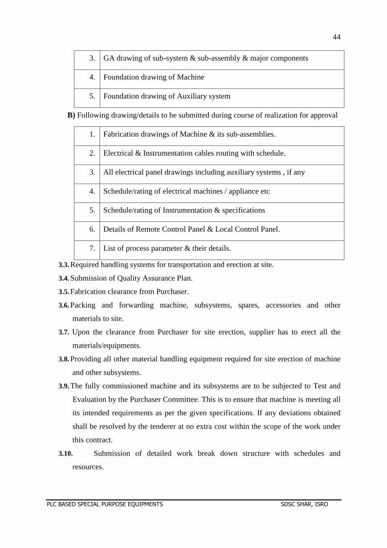
44
PLC BASED SPECIAL PURPOSE EQUIPMENTS SDSC SHAR, ISRO
3. GA drawing of sub-system & sub-assembly & major components
4. Foundation drawing of Machine
5. Foundation drawing of Auxiliary system
B) Following drawing/details to be submitted during course of realization for approval
1. Fabrication drawings of Machine & its sub-assemblies.
2. Electrical & Instrumentation cables routing with schedule.
3. All electrical panel drawings including auxiliary systems , if any
4. Schedule/rating of electrical machines / appliance etc
5. Schedule/rating of Instrumentation & specifications
6. Details of Remote Control Panel & Local Control Panel.
7. List of process parameter & their details.
3.3. Required handling systems for transportation and erection at site.
3.4. Submission of Quality Assurance Plan.
3.5. Fabrication clearance from Purchaser.
3.6. Packing and forwarding machine, subsystems, spares, accessories and other
materials to site.
3.7. Upon the clearance from Purchaser for site erection, supplier has to erect all the
materials/equipments.
3.8. Providing all other material handling equipment required for site erection of machine
and other subsystems.
3.9. The fully commissioned machine and its subsystems are to be subjected to Test and
Evaluation by the Purchaser Committee. This is to ensure that machine is meeting all
its intended requirements as per the given specifications. If any deviations obtained
shall be resolved by the tenderer at no extra cost within the scope of the work under
this contract.
3.10. Submission of detailed work break down structure with schedules and
resources.
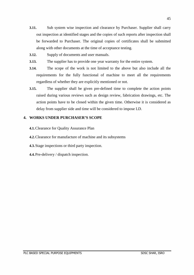
45
PLC BASED SPECIAL PURPOSE EQUIPMENTS SDSC SHAR, ISRO
3.11. Sub system wise inspection and clearance by Purchaser. Supplier shall carry
out inspection at identified stages and the copies of such reports after inspection shall
be forwarded to Purchaser. The original copies of certificates shall be submitted
along with other documents at the time of acceptance testing.
3.12. Supply of documents and user manuals.
3.13. The supplier has to provide one year warranty for the entire system.
3.14. The scope of the work is not limited to the above but also include all the
requirements for the fully functional of machine to meet all the requirements
regardless of whether they are explicitly mentioned or not.
3.15. The supplier shall be given pre-defined time to complete the action points
raised during various reviews such as design review, fabrication drawings, etc. The
action points have to be closed within the given time. Otherwise it is considered as
delay from supplier side and time will be considered to impose LD.
4. WORKS UNDER PURCHASER’S SCOPE
4.1. Clearance for Quality Assurance Plan
4.2. Clearance for manufacture of machine and its subsystems
4.3. Stage inspections or third party inspection.
4.4. Pre-delivery / dispatch inspection.
46
PLC BASED SPECIAL PURPOSE EQUIPMENTS SDSC SHAR, ISRO
SECTION –C
TECHNICAL
SPECIFICATIONS
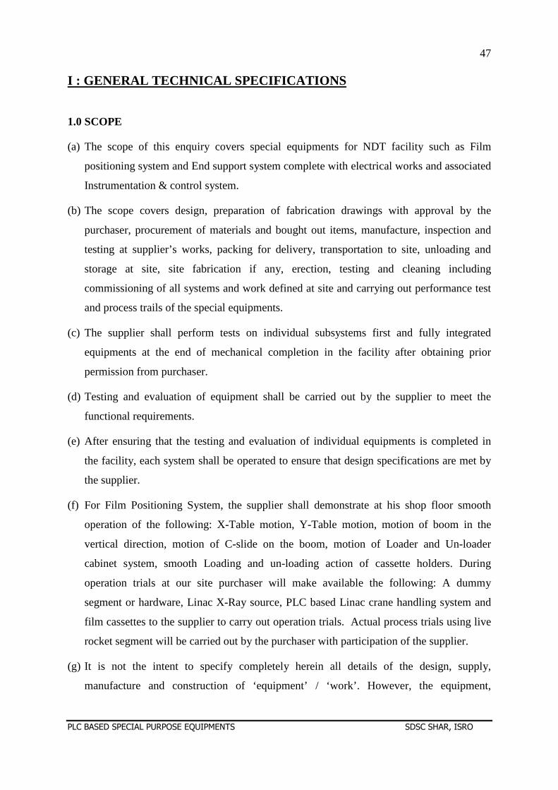
47
PLC BASED SPECIAL PURPOSE EQUIPMENTS SDSC SHAR, ISRO
I : GENERAL TECHNICAL SPECIFICATIONS
1.0 SCOPE
(a) The scope of this enquiry covers special equipments for NDT facility such as Film
positioning system and End support system complete with electrical works and associated
Instrumentation & control system.
(b) The scope covers design, preparation of fabrication drawings with approval by the
purchaser, procurement of materials and bought out items, manufacture, inspection and
testing at supplier’s works, packing for delivery, transportation to site, unloading and
storage at site, site fabrication if any, erection, testing and cleaning including
commissioning of all systems and work defined at site and carrying out performance test
and process trails of the special equipments.
(c) The supplier shall perform tests on individual subsystems first and fully integrated
equipments at the end of mechanical completion in the facility after obtaining prior
permission from purchaser.
(d) Testing and evaluation of equipment shall be carried out by the supplier to meet the
functional requirements.
(e) After ensuring that the testing and evaluation of individual equipments is completed in
the facility, each system shall be operated to ensure that design specifications are met by
the supplier.
(f) For Film Positioning System, the supplier shall demonstrate at his shop floor smooth
operation of the following: X-Table motion, Y-Table motion, motion of boom in the
vertical direction, motion of C-slide on the boom, motion of Loader and Un-loader
cabinet system, smooth Loading and un-loading action of cassette holders. During
operation trials at our site purchaser will make available the following: A dummy
segment or hardware, Linac X-Ray source, PLC based Linac crane handling system and
film cassettes to the supplier to carry out operation trials. Actual process trials using live
rocket segment will be carried out by the purchaser with participation of the supplier.
(g) It is not the intent to specify completely herein all details of the design, supply,
manufacture and construction of ‘equipment’ / ‘work’. However, the equipment,
48
PLC BASED SPECIAL PURPOSE EQUIPMENTS SDSC SHAR, ISRO
materials and services shall conform in all respects to high standards of engineering
design, workmanship and be capable of performing in continuous commercial operation
in a manner acceptable to the purchaser who will interpret the meaning of drawings and
specifications and shall have the power to reject any ‘work’/’equipment’ or material
which in his judgement are not in full accordance therewith.
(h) The complete PLC based Film positioning system (FPS) and End support system (ESS)
with accessories shall be designed, supplied, erected and commissioned within eleven
months from the date of release of purchase order. Supplier shall submit project execution
plan along with their offer, detailing the methodology of execution.
2.0 DESCRIPTION OF NDT PROCESS
(a) Non Destructive Testing (NDT) Facility at our site is configured to carry out high energy
X-Ray Radiography of finished solid propellant segments in horizontal attitude on a set of
high capacity Roller stands. The Roller stands are aligned and mounted on a large four-
legged table called Horizontal support structure (HSS) prior to loading of the solid rocket
segment.
(b) Prior to radiography each rocket segment is received inside the Exposure hall in
horizontal condition on a Special purpose Utility (SPU) vehicle. The combination of
segment, HSS and Roller stands is positioned at the designated position in the Exposure
hall of NDT Facility (Figure1). After driving away of SPU, the concrete sliding door of
the hall will be closed.
(c) After completion of radiography of rocket segment, the sliding door will be opened and
SPU vehicle will be allowed inside the hall. SPU will move underneath the HSS and lift it
along with segment and Roller stands to a height of 300 mm from finished floor level
(FFL) and transport to a nearby facility for tilting the segment to vertical condition and
storage subsequently.
(d) Two types of radiography techniques namely Propellant radiography and Tangential
Radiography are employed for inspection of any rocket segment.
(e) The details of the propellant radiography process are as given below:
(i) The ESS is brought to the position close to the axis of the segment from its parking
position by activating the drive of its Y-Table.
49
PLC BASED SPECIAL PURPOSE EQUIPMENTS SDSC SHAR, ISRO
(ii) The FPS is brought to the designated position close to the axis of the segment.
(iii)The FPS X-Table drive is activated to insert the boom of FPS into the port of the segment
till it emerges out on the other end of the segment where ESS is brought and positioned.
The boom is configured to carry and transport a Cassette Slide or C-Slide to and fro along
its entire length (~ 16 m).
(iv) The Y-Table of ESS is moved to align with respect to segment axis by operating from the
Local push button station.
(v) The Z-slide with its end adapter is raised through the activation its drive until it comes
into contact with FPS boom. There is a counter weight linked to the Z-slide of end
adapter through wire ropes and pulleys and moves in the opposite direction.
(vi) The Linac is moved by activating the X-drive of its crane manipulator to position for the
first X- ray shot.
(vii) The Loader and Un-Loader system of FPS is brought to its lowest position and
Cassette Holders loaded with four film cassettes each are stacked in the Loader cabinet.
The combined system is then raised to a height so that the loader cabinet aligns with the
C-Slide of the boom for the purpose of loading.
(viii) The Exposure hall is vacated and its two doors (Personnel Access door and Concrete
sliding door) are closed. From now on all operations will be controlled from Control
Room and film exposure sequences will be carried out either in semi-auto mode with
manual operation of Linac system or in automatic mode in case the linking of X-ray
Linac system with the PLC is incorporated by the Purchaser.
(ix) First the Cassette holder with fresh cassettes is loaded from the Loading cabinet into the
C-Slide by operating the corresponding Loader air-cylinder
(x) The C-Slide is moved along the length of the boom by chain-sprocket arrangement to the
first X-ray shot position of the rocket segment, locating the cassette holder opposite to the
Linac head.
(xi) X-ray exposure is given to the films of the cassette holder, the C-Slide then moves to the
position opposite of Un-loader cabinet. The exposed cassette holder is unloaded into to
the Un-loader cabinet, the C-Slide moves to the position opposite to the Loader cabinet
and second fresh cassette holder is loaded into C-Slide by air-cylinder.
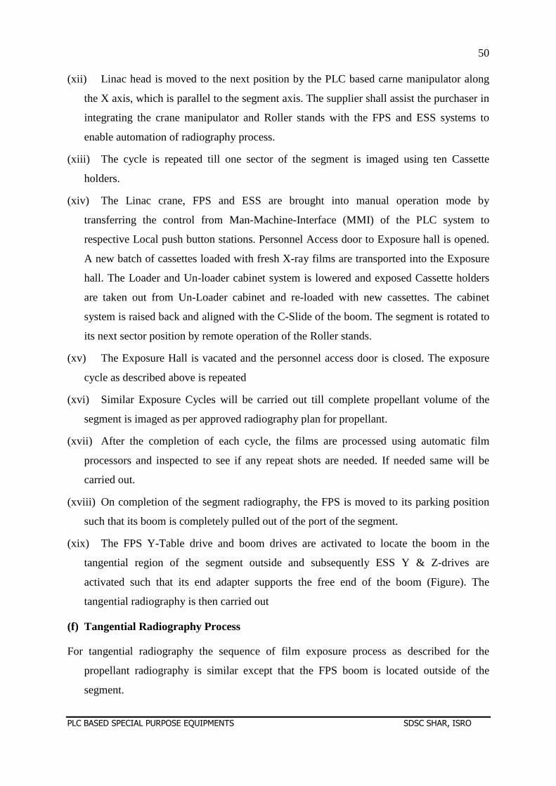
50
PLC BASED SPECIAL PURPOSE EQUIPMENTS SDSC SHAR, ISRO
(xii) Linac head is moved to the next position by the PLC based carne manipulator along
the X axis, which is parallel to the segment axis. The supplier shall assist the purchaser in
integrating the crane manipulator and Roller stands with the FPS and ESS systems to
enable automation of radiography process.
(xiii) The cycle is repeated till one sector of the segment is imaged using ten Cassette
holders.
(xiv) The Linac crane, FPS and ESS are brought into manual operation mode by
transferring the control from Man-Machine-Interface (MMI) of the PLC system to
respective Local push button stations. Personnel Access door to Exposure hall is opened.
A new batch of cassettes loaded with fresh X-ray films are transported into the Exposure
hall. The Loader and Un-loader cabinet system is lowered and exposed Cassette holders
are taken out from Un-Loader cabinet and re-loaded with new cassettes. The cabinet
system is raised back and aligned with the C-Slide of the boom. The segment is rotated to
its next sector position by remote operation of the Roller stands.
(xv) The Exposure Hall is vacated and the personnel access door is closed. The exposure
cycle as described above is repeated
(xvi) Similar Exposure Cycles will be carried out till complete propellant volume of the
segment is imaged as per approved radiography plan for propellant.
(xvii) After the completion of each cycle, the films are processed using automatic film
processors and inspected to see if any repeat shots are needed. If needed same will be
carried out.
(xviii) On completion of the segment radiography, the FPS is moved to its parking position
such that its boom is completely pulled out of the port of the segment.
(xix) The FPS Y-Table drive and boom drives are activated to locate the boom in the
tangential region of the segment outside and subsequently ESS Y & Z-drives are
activated such that its end adapter supports the free end of the boom (Figure). The
tangential radiography is then carried out
(f) Tangential Radiography Process
For tangential radiography the sequence of film exposure process as described for the
propellant radiography is similar except that the FPS boom is located outside of the
segment.
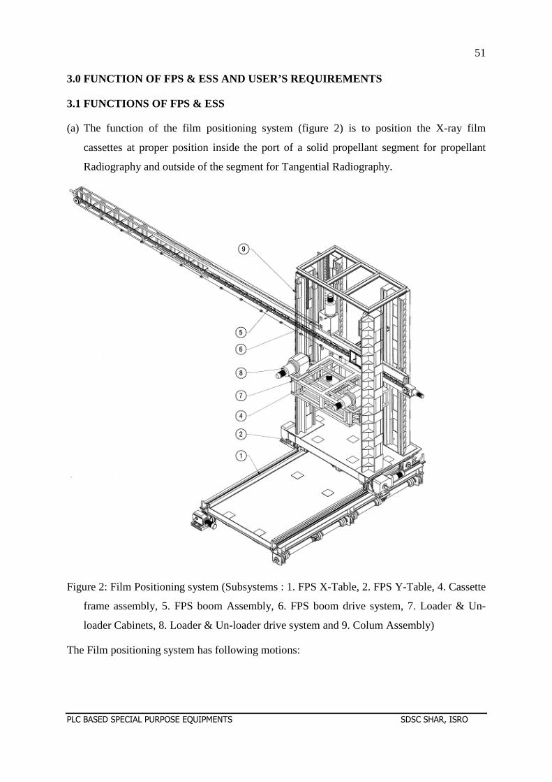
51
PLC BASED SPECIAL PURPOSE EQUIPMENTS SDSC SHAR, ISRO
3.0 FUNCTION OF FPS & ESS AND USER’S REQUIREMENTS
3.1 FUNCTIONS OF FPS & ESS
(a) The function of the film positioning system (figure 2) is to position the X-ray film
cassettes at proper position inside the port of a solid propellant segment for propellant
Radiography and outside of the segment for Tangential Radiography.
Figure 2: Film Positioning system (Subsystems : 1. FPS X-Table, 2. FPS Y-Table, 4. Cassette
frame assembly, 5. FPS boom Assembly, 6. FPS boom drive system, 7. Loader & Un-
loader Cabinets, 8. Loader & Un-loader drive system and 9. Colum Assembly)
The Film positioning system has following motions:
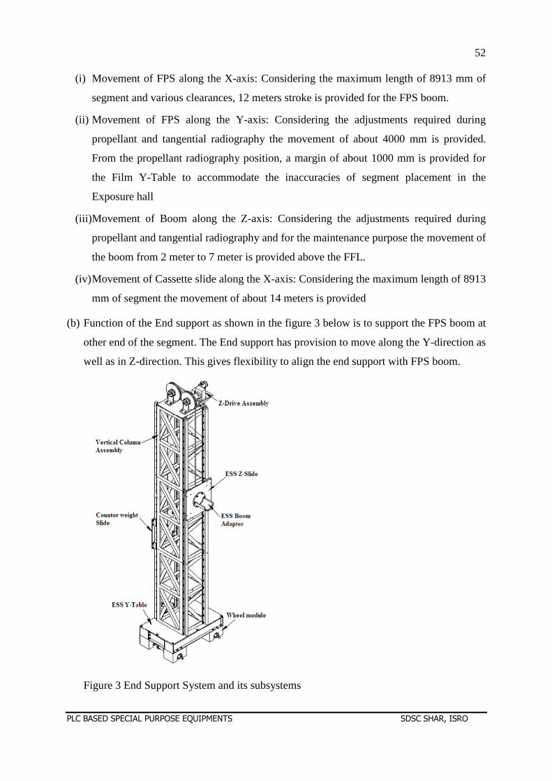
52
PLC BASED SPECIAL PURPOSE EQUIPMENTS SDSC SHAR, ISRO
(i) Movement of FPS along the X-axis: Considering the maximum length of 8913 mm of
segment and various clearances, 12 meters stroke is provided for the FPS boom.
(ii) Movement of FPS along the Y-axis: Considering the adjustments required during
propellant and tangential radiography the movement of about 4000 mm is provided.
From the propellant radiography position, a margin of about 1000 mm is provided for
the Film Y-Table to accommodate the inaccuracies of segment placement in the
Exposure hall
(iii)Movement of Boom along the Z-axis: Considering the adjustments required during
propellant and tangential radiography and for the maintenance purpose the movement of
the boom from 2 meter to 7 meter is provided above the FFL.
(iv) Movement of Cassette slide along the X-axis: Considering the maximum length of 8913
mm of segment the movement of about 14 meters is provided
(b) Function of the End support as shown in the figure 3 below is to support the FPS boom at
other end of the segment. The End support has provision to move along the Y-direction as
well as in Z-direction. This gives flexibility to align the end support with FPS boom.
Figure 3 End Support System and its subsystems
53
PLC BASED SPECIAL PURPOSE EQUIPMENTS SDSC SHAR, ISRO
(c) End support system has following motion provisions:
(i) Movement of ESS along Y-axis. When the SPU enters the Exposure hall the ESS is
parked away from the path of SPU. Considering this a stroke of about 4000 mm shall be
provided.
(ii) Movement of the ESS end adapter along the Z-axis is provided to cater to different height
levels of FPS boom for propellant and tangential radiography. The ESS Y-Table length is
adjusted to about 1900 mm so that it can be parked in the designated corner of the
Exposure hall.
(d) Speed limits of FPS subsystems are as follows
(i) FPS X-Table : 2000 mm/min.
(ii) FPS Y-Table : 2000 mm/min.
(iii) Boom along Z-axis : 1000 mm/min.
(iv) Loader & Un-loader cabinet system along Z-axis : 1000 mm/min.
(v) C-Slide along boom length (X-axis) : 5000 mm/min
3.2 OTHER CONSIDERATIONS
(a) Allowable stresses for the design of structures shall be as per IS: 800. Allowable stresses
of structural steel shall not exceed 120 MPa for body metal and 100 MPa for welds.
(b) The rocket segment will be positioned at the designated location in the Exposure Hall
parallel to X-axis within ± 5 mm using SPU.
(c) Rails shall be supplied and laid by supplier on the foundation provided in the floor. In
laying the rails it is to be ensured that the rail tops are in flush with the FFL.
3.3 USER’S REQUIREMENTS
(a) Refer drawing for the General Arrangement of Exposure hall.
(b) Centerline of the rocket segment in horizontal orientation along its length when placed on
high capacity roller stands may be at about 5250mm from FFL.
(c) Approximate cassette dimensions are 430 mm length x 330 mm width x 15 mm thickness.
(e) Cassette weight is approximately 30 N.
(f) FPS & ESS are configured to carry out both propellant radiography and tangential
radiography of rocket segments.
54
PLC BASED SPECIAL PURPOSE EQUIPMENTS SDSC SHAR, ISRO
(g) For propellant Radiography the cassettes are to be kept inside the propellant port of
segment for single wall single image radiography.
(h) For Tangential Radiography, cassettes are to be kept outside of the segment in its top
tangential region as close as possible for imaging of interfaces.
(i) Four cassettes are to be kept in vertical plane at a time in a cassette holder frame along the
length of segment with an overlap of about 50 mm between the cassettes.
(j) Horizontal distance of the cassette holder from the Linac X-ray source is about 7 m for
both propellant and tangential radiography.
(k) Cassette positioning using Film positioning system shall cover the entire length of the
segment for imaging the propellant and interfaces as per the approved radiography plans.
4.0 DESIGN CRITERIA
(a) All structures shall be as per provisions of IS: 800
(b) Pneumatic system shall be designed for 5 bar maximum. The components shall however
be suitable for 10 bar (g) design pressure.
(c) Speed limits for different subsystems of FPS and ESS shall be as in 3.1 (d).
(d) Standard off-the-shelf pneumatic elements shall be used
5.0 EQUIPMENT AND SERVICES TO BE PROVIDED BY THE SUPPLI ER
(a) Detailed Design Drawings, Manufacturing drawings and Assembly drawings.
(b) Quality assurance plan for manufacture and testing.
(c) Quality records, history dockets, as built drawings and all documentation related to
manufacturing, inspection, testing and erection.
(d) Assembly Procedures, maintenance procedures and operating procedures.
(e) Manufacture and Supply of the following systems.
(f) Film Positioning System (FPS) broadly comprising of following sub-systems:
(i) FPS X-Table.
(ii) FPS Y-Table
(iii) FPS Columns with linear guides
55
PLC BASED SPECIAL PURPOSE EQUIPMENTS SDSC SHAR, ISRO
(iv) FPS Boom Z- Slide system
(v) FPS Boom
(v) Cassette Slide
(vi) Loader and Un-Loader Cabinet system.
(vii) All electric and pneumatic drive components, controllers and position sensing
devices
(viii) Set of Rails for movement of FPS X-Table & Y-Table
(g) End Support System (ESS) broadly comprising of the following:
(i) ESS Y-Table
(ii) ESS Column
(iii) ESS Z-Slide and Counter weight slide
(iv) ESS Boom Adapter
(v) Set of Rails for movement of ESS Y-Table
(i) Electrical works as per Section II
(j) All instrumentation & control systems (SECTION-III) and cabling required in order
to facilitate manual, semi-automatic or automatic operation of FPS & ESS from the
Control room apart from manual operation of the same locally in the Exposure hall
using corresponding Local push button stations.
(k) Compressed air for loading cassette holders with fresh film cassettes from Loader
cabinet into the C-Slide and unloading of exposed cassette holders from the C-slide
into the Un-Loader cabinet shall be provided at a designated location in one of the
service rooms of the NDT Building at a distance of 160 m from FPS. The necessary
piping / tubing including on line instrumentation, pressure reducing valves, FRL unit
shall be provided by the supplier.
(l) Painting of all the equipments and structures listed above.
(m) Necessary equipments required for testing, cleaning and flushing of the system.
(n) Grouting of the equipments.
(o) First fill of oil, grease, lubricants as required during start-up and commissioning.
56
PLC BASED SPECIAL PURPOSE EQUIPMENTS SDSC SHAR, ISRO
(p) One complete set of special maintenance tools required for normal maintenance of the
equipments.
(q) One set of start-up and commissioning spares.
(r) Recommended spares for two years of trouble free operation of FPS & ESS.
(s) Operation and maintenance manuals for the complete system.
(t) Auxiliary steel / structural steel for supporting the equipment, piping, cabling, etc.
(u) All anchor bolts / foundation bolts, nuts, washers and inserts to be embedded into the
concrete for the cable chain systems of FPS & ESS and piping.
(v) All hardware e.g. Nuts, bolts & gasket, anchor fasteners etc., including breaking of
walls are included in the supplier's scope. No separate claim shall be entertained, in
this respect. At least 10% extra hardware shall be provided for any installation / fixing
work. This is to ensure ready availability of hardware in case of loss of some
hardware during installation.
(w) For providing supports for piping, cable chain systems, rails and the equipments the
supplier shall supply suitable EP and fix to RC Walls using anchor fasteners.
(x) Structural steel supports for piping and cable chain systems.
(y) Drawings for review and approval by the purchaser.
(z) Operation and maintenance manuals.
(aa) For standard bought out components (gear box, motor, pneumatic/ hydraulic
cylinder, etc.), the supplier may use the specific make as indicated in the GA
drawing / specification. Alternatively the supplier may use equivalent component of
a different make of repute. In such cases the supplier shall submit calculations /
justification showing adequacy of the selected component for approval from the
purchaser before procurement. The supplier shall also carry out required design
modifications to suit the mounting of the selected components.
(bb) Shop floor inspection and tests shall be as per the specifications. Wherever not
specified, the shop floor inspection tests shall be as per recent codes applicable.
(cc) The supplier’s scope of work shall also include erection, testing, start up,
commissioning, operational & process trials covered in this specification.
57
PLC BASED SPECIAL PURPOSE EQUIPMENTS SDSC SHAR, ISRO
(dd) Training of purchaser’s personnel.
(ee) Any other system not indicated herein, but required to make the system complete
shall be included and provided at no extra cost.
6.0 EQUIPMENT & SERVICES TO BE PROVIDED BY PURCHASER
The following are the equipments and services that shall be provided by the purchaser:
(i) NDT Facility consisting of Exposure hall and service rooms.
(ii) Power control centre (PCC) for tapping of electrical power
(iii) Linac X-Ray Machine
(iv) PLC based Overhead crane handling system with Linac.
(v) Foundation for Rails of Film Positioning System and End Support system.
(vi) Cable trenches that connect service rooms and Exposure hall.
(vii) Necessary openings on brick wall and RCC walls or trenches shall be provided for
routing the piping, cabling from service and control rooms to the Exposure hall.
However wherever openings are not available breaking of wall and making of
opening after routing of piping, cabling shall be done by the supplier at no extra cost.
(viii) Cassettes with fresh X-Ray films for performing Radiography process trials.
(ix) 60 t capacity EOT crane inside the Exposure hall.
(x) Handling tackles.
(xi) Horizontal Support Structure (HSS) for mounting Roller stands
(xii) Dummy rocket segment or hardware
(xiii) Roller stands for rotating solid propellant rocket segments.
(xiv) Fire protection system for the entire facility.
7.0 CODES AND STANDARDS
(a) All equipments / systems and works covered under this specification shall comply with
all currently applicable statutes, regulations, standards and safety codes in the locality
where the equipment will be installed.
(b) In particular, the latest editions of the following standards are applicable
Steel for general structural purposes IS 2062
58
PLC BASED SPECIAL PURPOSE EQUIPMENTS SDSC SHAR, ISRO
Plates and Stiffeners IS 2062 GR-B
SQ. Hollow sections IS 4923 YST 310 grade
Rolled sections and special sections IS:808, IS:1161, IS:1173,
IS:1252, IS:1730, IS:1731,
IS:1732, IS:1863, IS: 1864,
IS:2314
(c) Other national standards established to be equivalent or superior to the codes and
standards specified are also acceptable. The supplier shall furnish English translation
of all standards specified in this specification.
(d) In the event of any conflict between the codes and standards referred to in the
specification and the requirements of this specification, the more stringent of these
requirements shall govern.
(e) Unless indicated otherwise, all codes and standards referred to in this enquiry
specification shall be understood to be the latest version on the date of offer made by
the supplier.
8.0 CONFIGURATION OF FPS & ESS
The configuration of Film Positioning system and End Support System may be made in the
following sequence:
(i) Fresh Cassette in Cassette Holders are placed in the Loader cabinet
(ii) Exposed Cassette Holders are placed in the Un-Loader cabinet
(iii)Loader and Un-Loader cabinets are mounted on Film Lift
(iv) Film Lift is mounted on Y-Table
(v) Cassette Holder is held in C-Slide
(vi) C-Slide (along the length of segment) is supported on the boom of the Z Travel
Arrangement.
(vii) Boom Vertical Travel Arrangement is on Vertical Column Assembly.
(viii) Vertical Column Assembly is mounted on FPS-Y Table Assembly.
(ix) FPS Y-Table is mounted on FPS X-Table.
(x) FPS X-Table is placed on FPS Rails embedded in the floor of Exposure Hall.
59
PLC BASED SPECIAL PURPOSE EQUIPMENTS SDSC SHAR, ISRO
(xi) ESS Adapter and counter weight are mounted on ESS Vertical Slides
(xii) ESS Vertical Slides are mounted on ESS Column.
(xiii) ESS Column is mounted on ESS Y-Table.
(xiv) ESS Y-Table is placed on the ESS rails embedded in the floor of Exposure Hall
Note: FPS boom is configured to cover the entire length of the longest rocket segment.
The free end of the boom is supported using ESS.
The details of drawings of FPS and ESS are as given below
8.1 General Arrangement drawing of FPS (Dwg.No.10-04-200-24-01/A1 (1 sheet))
8.2 General Arrangement drawing of FPS X & Y-Tables(Dwg. No. 10-04-200-24-02/A1
(1 sheet))
8.3 FPS X-Table Assembly (Dwg. No. 10-04-200-24-03/A1 (1 to 5 sheets))
8.4 FPS Y-Table Assembly (Dwg. No. 10-04-200-24-04/A1(1 to 5 sheets))
8.5 Rail Layout (Dwg. No. 10-04-200-24-05/A1, (1 sheet))
8.6 Cassette Holder (Dwg. No. 10-04-200-24-06/A1, (1 sheet))
(i) Cassette holder is specially configured to hold the loaded X-Ray film cassettes for
propellant and tangential radiography.
(ii) It has four slots arranged to provide an effective film area of about 1100 mm x 400 mm.
(iii)Cassettes when loaded in the Cassette holder will have an overlap of 50 mm between
them.
8.7 FPS Boom (Refer Dwg. No. 10-04-200-24-007/A1 (1 to 5 sheets))
(i) The boom moves inside the segment for propellant radiography and outside the
segment for interface radiography. The cross section of the boom is limited by the
size of the propellant port of the rocket segment.
(ii) The boom is supported at other end by the End adapter of ESS, which is movable to
clear the passage for SPU entry.
(iii) The end face of the boom at its free end shall be provided with at least 9 numbers of
intrinsic safe photo sensors for the purpose of detection of propellant surface and safe
travel through the propellant port
60
PLC BASED SPECIAL PURPOSE EQUIPMENTS SDSC SHAR, ISRO
(iv) The boom is provided with a drive module for the Cassette Slide and an air cylinder
for unloading the exposed cassette holder in the Un-Loader cabinet. The Cassette
Slide is accurately positioned at the Un-loader cabinet for this function.
(v) The supplier shall design and provide removable cover for the boom assembly
entering the propellant port of rocket segment meeting the following requirements.
The boom shall be provided with covers for enveloping the moving parts to prevent
egress of dirt, oil etc. on the port surface. Each cover shall be made in two parts. One
part shall be screwed to a portion of upper half of boom assembly and other part shall
be screwed to the lower half of the boom. The covers shall be easily removable for
inspection and maintenance. The covers shall not hinder free movement of the
cassette slide with cassette holder on the boom. The cover design of the supplier shall
be approved by purchaser before manufacture.
8.8 Boom Drive system (Dwg. No. 10-04-200-24-08/A1 (1 sheet))
8.9 Cassette Slide or C-Slide (Dwg. No. 10-04-200-24-09/A1 (1 to 6 sheets))
(i) C-Slide moves the cassette holder loaded fresh X-Ray film cassettes to the desired
position along the length of the boom.
(ii) Cassette slide is guided along the FPS Boom.
(iii) The movement of the Cassette slide or C-Slide is by chain sprocket arrangement.
(iv) The C-Slide is driven by a suitable drive module.
8.10 Loader and Un-Loader cabinets (Refer Dwg. No. 10-04-200-24-10/A1 (1 sheet))
(i) Loader and Un-Loader cabinets are designed to hold 20 cassette holders (20 x 4 = 80 Film
cassettes) at a time.
(ii) When loaded with a cassette holder the C-Slide transports it along the boom length and
locates it at any desired position by PLC program.
(iii)Loading of cassette holder into the C-Slide and unloading of cassette holder from the C-
Slide into the Un-loader cabinet is by respective Air cylinders.
(iv) The C-Slide with cassette holder slides along the length of the boom.
(v) The sprockets shall be made up of non-sparking material such as copper-beryllium or
phosphor-bronze.
61
PLC BASED SPECIAL PURPOSE EQUIPMENTS SDSC SHAR, ISRO
(vi) At the end of two cycles of radiography process each involving 10 cassette holders, the
Loader and Un-loader cabinet system is lowered to a suitable height. Exposed cassette
holders are collected from the Un-loader cabinet and the film cassettes are taken out from
them. Fresh cassettes are then loaded into the cassette holders and the same are stacked
into the Loader cabinet manually.
(vii) At the end of reloading of Loader cabinet the system is again raised and positioned to
align with the C-Slide of the Boom by manual operation.
8.11 Column Assembly (Dwg. No. 10-04-200-24-11/A1 (1 sheet))
8.12 END SUPPORT SYSTEM DRAWINGS
Refer Dwg. Nos. : (201-73-004-0-R1, 201-73-041-2-R2 & 201-73-044-1-R1)
(i) The ESS comprises Y-Table, Column, Vertical Slides and Boom Adapter and Counter
weight mounted on the vertical slides.
(ii) ESS boom Adapter is dimensioned to provide propped support to the adapter on the
Boom. The fit is loose to avoid loads due to flexing of the boom.
(iii) The boom of the FPS passes through the segment port for propellant radiography (and
gets positioned outside of the segment for tangential radiography) and the end of the
boom is supported using the ESS boom adapter.
(iv) When the SPU arrives, the ESS is moved and parked at a distance close to the wall of
Exposure Hall. After the SPU leaves the NDT facility, the ESS is brought to the
desired position.
(v) The height of the ESS adapter is adjusted to suit to the height of boom.
9.0 FPS and ESS Cable System
The details of cables required are described in Sections II and III.
10.0 OPERATION SEQUENCE AND INTERLOCKS
The operating sequence during radiography is as follows. Home position of the FPS is
defined by following status of the various subsystems.
10.1 Film positioning system
(a) X-Table parking at the mechanical stop away from the door entry.
(b) Y-table parking at the mechanical stop away from the segment location.
62
PLC BASED SPECIAL PURPOSE EQUIPMENTS SDSC SHAR, ISRO
(c) Z-slide parking at the bottom-most position.
(d) Loader & Un-loader cabinet system is at the lowest position
(e) C-Slide parking at Un-loader cabinet.
10.2 End Support system
(f) ESS parking at its home position away from the sliding door entry.
10.3 Preliminary preparation
(a) Rocket segment is transported to NDT facility from Inhibition facility on 400 t capacity
roller stands mounted on HSS by Self Propelled Unit (SPU) in horizontal attitude.
(b) Entry door of the exposure bay of Exposure hall is opened. It gives audio-visual alarm
indicating that the door of the exposure hall is opened. The operators enter into the
exposure hall.
(c) Rear end of SPU enters Exposure hall and the SPU halts such that the front of the SPU is
at the designated position in the facility from the entry door.
(e) SPU positions itself above the location specially prepared for accepting HSS. HSS is
lowered by lowering the SPU. Support structure aligns itself such that it is located within
±5 mm of its desired position. SPU is taken away from the Exposure hall and the door is
closed.
10.4 Preparation for Propellant Radiography
(i) For propellant Radiography, the boom of the Film Positioning system needs to be inserted
into the port of the rocket segment.
(ii) Film exposure by X-ray beam activation is possible automatically when the film cassettes
& Linac have reached their designated positions and a signal to that confirmation is
available from the PLC.
(iii)The automatic activation of X-Ray beam from Linac control console could be given after
a time lapse of about 2 minutes to allow the dampening of vibrations of the Linac head.
However, it is supplier to attempt a complete automated operation involving exposure of
films over one complete length of the segment after manual activation of the beam is tried
sufficient number of times and results are confirmed satisfactory. Till then this provision
in the programming can be put on hold.
63
PLC BASED SPECIAL PURPOSE EQUIPMENTS SDSC SHAR, ISRO
(iv) The C-Slide moves and aligns with the Un-loader. The cassette holder is unloaded into
the Un-Loader cabinet. If the number of film cassettes in any cassette holder is less than
4, as sensed by the film cassette proximity switches an audio / visual alarm is raised and
the operator can carry the operation only in manual mode. This provision is made to warn
the operator that less than required film cassettes are being exposed for a special case
such as re-shots or additional shots.
10.5 For tangential radiography
(i) All the operations for the tangential radiography are similar to that of propellant
radiography except that the FPS, ESS and Linac crane are positioned and manually
locked in the tangential radiography mode.
(i) Following interlocks shall be provided for the slides of FPS & Linac crane:
• Z-slide shall not move unless the Y-slide is aligned & locked in position.
• X-slide shall not move unless the Z-slide is aligned & locked in position.
The above interlocks shall be achieved in the PLC in both auto & manual modes.
(iii) The C-slide shall move only after the X, Y & Z-slides of the film positioning system
and X, Y & Z-slides of the Linac crane are in aligned positions.
(x) Full Cassette Holder is detected at the Film Loading position by proximity switches.
If all 4 cassettes are missing further operation of FPS will not take place. If one or two
cassettes are missing, loud audio and/or clear Visual warning system will be actuated.
Under this condition the exposure can take place only under manual operation. The
automated system is bypassed for the manual operation.
(ix) If the boom passing through the segment port hits the end limit switch on other side or
if obstruction is sensed in the segment port for movement of the boom, the movement
of the X-slide shall be stopped immediately. To detect obstruction in the passage of
the boom through the segment port in order to avoid rubbing on the propellant in the
segment 9 numbers of photoelectric sensors need to be mounted at the free end of the
boom. With the usage of photoelectric sensors, if any obstruction sensed in the path of
movement of the Boom, the PLC can be programmed to automatically stop the
movement of the boom. Hence no operator intervention is required in this option.
(x) Linac crane shall be in off position till new position of cassette holder is achieved
after picking new cassette holder.
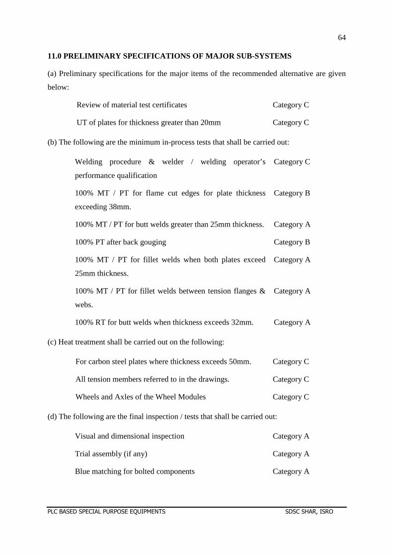
64
PLC BASED SPECIAL PURPOSE EQUIPMENTS SDSC SHAR, ISRO
11.0 PRELIMINARY SPECIFICATIONS OF MAJOR SUB-SYSTEM S
(a) Preliminary specifications for the major items of the recommended alternative are given
below:
Review of material test certificates Category C
UT of plates for thickness greater than 20mm Category C
(b) The following are the minimum in-process tests that shall be carried out:
Welding procedure & welder / welding operator’s
performance qualification
Category C
100% MT / PT for flame cut edges for plate thickness
exceeding 38mm.
Category B
100% MT / PT for butt welds greater than 25mm thickness. Category A
100% PT after back gouging Category B
100% MT / PT for fillet welds when both plates exceed
25mm thickness.
Category A
100% MT / PT for fillet welds between tension flanges &
webs.
Category A
100% RT for butt welds when thickness exceeds 32mm. Category A
(c) Heat treatment shall be carried out on the following:
For carbon steel plates where thickness exceeds 50mm. Category C
All tension members referred to in the drawings. Category C
Wheels and Axles of the Wheel Modules Category C
(d) The following are the final inspection / tests that shall be carried out:
Visual and dimensional inspection Category A
Trial assembly (if any) Category A
Blue matching for bolted components Category A
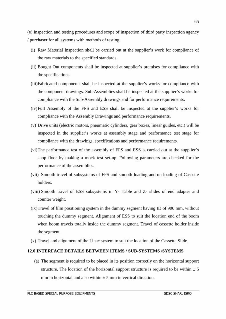
65
PLC BASED SPECIAL PURPOSE EQUIPMENTS SDSC SHAR, ISRO
(e) Inspection and testing procedures and scope of inspection of third party inspection agency
/ purchaser for all systems with methods of testing
(i) Raw Material Inspection shall be carried out at the supplier’s work for compliance of
the raw materials to the specified standards.
(ii) Bought Out components shall be inspected at supplier’s premises for compliance with
the specifications.
(iii)Fabricated components shall be inspected at the supplier’s works for compliance with
the component drawings. Sub-Assemblies shall be inspected at the supplier’s works for
compliance with the Sub-Assembly drawings and for performance requirements.
(iv) Full Assembly of the FPS and ESS shall be inspected at the supplier’s works for
compliance with the Assembly Drawings and performance requirements.
(v) Drive units (electric motors, pneumatic cylinders, gear boxes, linear guides, etc.) will be
inspected in the supplier’s works at assembly stage and performance test stage for
compliance with the drawings, specifications and performance requirements.
(vi) The performance test of the assembly of FPS and ESS is carried out at the supplier’s
shop floor by making a mock test set-up. Following parameters are checked for the
performance of the assemblies.
(vii) Smooth travel of subsystems of FPS and smooth loading and un-loading of Cassette
holders.
(viii) Smooth travel of ESS subsystems in Y- Table and Z- slides of end adapter and
counter weight.
(ix) Travel of film positioning system in the dummy segment having ID of 900 mm, without
touching the dummy segment. Alignment of ESS to suit the location end of the boom
when boom travels totally inside the dummy segment. Travel of cassette holder inside
the segment.
(x) Travel and alignment of the Linac system to suit the location of the Cassette Slide.
12.0 INTERFACE DETAILS BETWEEN ITEMS / SUB-SYSTEMS /SYSTEMS
(a) The segment is required to be placed in its position correctly on the horizontal support
structure. The location of the horizontal support structure is required to be within ± 5
mm in horizontal and also within ± 5 mm in vertical direction.
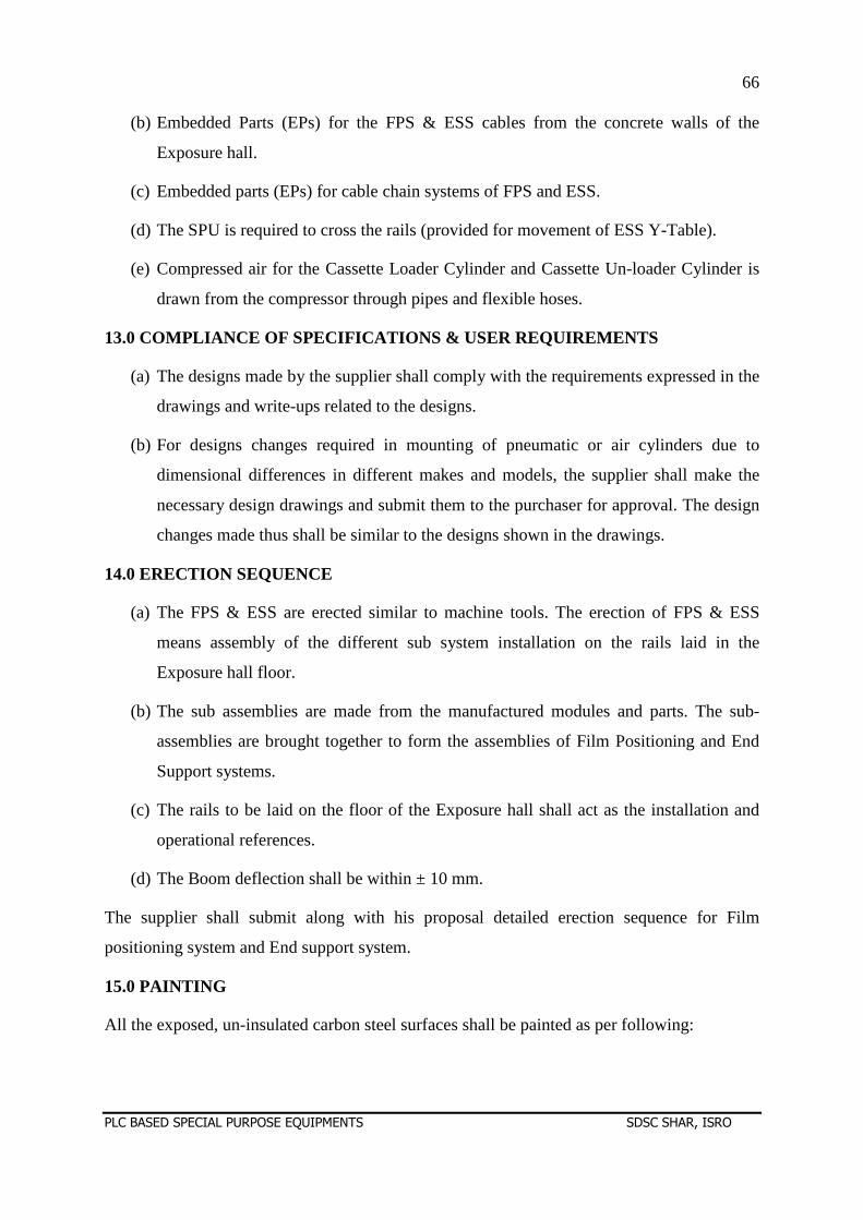
66
PLC BASED SPECIAL PURPOSE EQUIPMENTS SDSC SHAR, ISRO
(b) Embedded Parts (EPs) for the FPS & ESS cables from the concrete walls of the
Exposure hall.
(c) Embedded parts (EPs) for cable chain systems of FPS and ESS.
(d) The SPU is required to cross the rails (provided for movement of ESS Y-Table).
(e) Compressed air for the Cassette Loader Cylinder and Cassette Un-loader Cylinder is
drawn from the compressor through pipes and flexible hoses.
13.0 COMPLIANCE OF SPECIFICATIONS & USER REQUIREMEN TS
(a) The designs made by the supplier shall comply with the requirements expressed in the
drawings and write-ups related to the designs.
(b) For designs changes required in mounting of pneumatic or air cylinders due to
dimensional differences in different makes and models, the supplier shall make the
necessary design drawings and submit them to the purchaser for approval. The design
changes made thus shall be similar to the designs shown in the drawings.
14.0 ERECTION SEQUENCE
(a) The FPS & ESS are erected similar to machine tools. The erection of FPS & ESS
means assembly of the different sub system installation on the rails laid in the
Exposure hall floor.
(b) The sub assemblies are made from the manufactured modules and parts. The sub-
assemblies are brought together to form the assemblies of Film Positioning and End
Support systems.
(c) The rails to be laid on the floor of the Exposure hall shall act as the installation and
operational references.
(d) The Boom deflection shall be within ± 10 mm.
The supplier shall submit along with his proposal detailed erection sequence for Film
positioning system and End support system.
15.0 PAINTING
All the exposed, un-insulated carbon steel surfaces shall be painted as per following:
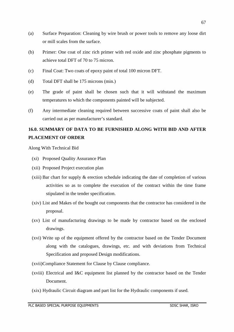
67
PLC BASED SPECIAL PURPOSE EQUIPMENTS SDSC SHAR, ISRO
(a) Surface Preparation: Cleaning by wire brush or power tools to remove any loose dirt
or mill scales from the surface.
(b) Primer: One coat of zinc rich primer with red oxide and zinc phosphate pigments to
achieve total DFT of 70 to 75 micron.
(c) Final Coat: Two coats of epoxy paint of total 100 micron DFT.
(d) Total DFT shall be 175 microns (min.)
(e) The grade of paint shall be chosen such that it will withstand the maximum
temperatures to which the components painted will be subjected.
(f) Any intermediate cleaning required between successive coats of paint shall also be
carried out as per manufacturer’s standard.
16.0. SUMMARY OF DATA TO BE FURNISHED ALONG WITH BI D AND AFTER
PLACEMENT OF ORDER
Along With Technical Bid
(xi) Proposed Quality Assurance Plan
(xii) Proposed Project execution plan
(xiii) Bar chart for supply & erection schedule indicating the date of completion of various
activities so as to complete the execution of the contract within the time frame
stipulated in the tender specification.
(xiv) List and Makes of the bought out components that the contractor has considered in the
proposal.
(xv) List of manufacturing drawings to be made by contractor based on the enclosed
drawings.
(xvi) Write up of the equipment offered by the contractor based on the Tender Document
along with the catalogues, drawings, etc. and with deviations from Technical
Specification and proposed Design modifications.
(xvii) Compliance Statement for Clause by Clause compliance.
(xviii) Electrical and I&C equipment list planned by the contractor based on the Tender
Document.
(xix) Hydraulic Circuit diagram and part list for the Hydraulic components if used.
68
PLC BASED SPECIAL PURPOSE EQUIPMENTS SDSC SHAR, ISRO
(xx) Fabrication and erection sequence proposed to be adopted.
(xxi) Names of suppliers for steel materials.
(xxii) Performance curves/rating charts used for selection of equipment for all the systems
shall be furnished along with the bid, with the duty points duly marked on them.
(xxiii) All sheets of Section F duly filled in, signed and stamped.
(xxiv) Electrical load list indicating rating and quantity.
17.0 DETAILED ENGINEERING DOCUMENTS AFTER ISSUE OF LETTER OF
INTENT (LOI)
(a) The detail data and drawings, as per schedule indicated in the following clause of this
section.
(b) Final Quality Assurance Plan.
(c) Pneumatic Circuit Diagram as finalized for placement of order
(d) Final Purchase orders for bought out components
(e) Test Certificates for Steel Materials
(f) Procedures for Welding, Qualifications of Welders, Painting and Finishing
(g) Packaging and Transportation Plan
(h) Erection Plan
(i) Inspection and Testing Plan
(j) Commissioning Plan
(k) Final data sheet B.
(l) Spare parts list.
17.1 Final Documents
(i) Operation and maintenance manuals.
(ii) Quality assurance documentation specific for the project.
(iii) Final as built documentation folder containing all items for future reference.
18.0 BOUGHT-OUT ITEMS
The bought-out items shall be of following make only. If for any reason, the supplier plans to
use different make(s), prior approval for the same shall be obtained from the purchaser.
69
PLC BASED SPECIAL PURPOSE EQUIPMENTS SDSC SHAR, ISRO
(a) FASTENERS : TVS, GKW, UNBRAKO
(b) BEARINGS : SKF, FAG
(c) FLAME-PROOF MOTORS WITH IN-BUILT BRAKES: PBL, SEW EURODRIVE,
POWER BUILD
(d) GEAR BOXES : SEW EURODRIVE
(e) PLUMMER BLOCKS : FAG
(f) LINEAR GUIDE : THK
(g) RACK : ATLANTA
(h) COUPLINGS : FENNER
(i) VFD : SIEMENS
(j) EX-PROOF ABSOLUTE ENCODERS : P & F
(k) INTRINSIC SAFE RELAYS : P & F
(l) PLC : SIEMENS
(m) CABLE DRAG CHAIN : IGUS
(n) CABLES : LAPP
(o) SWITCH GEARS : SIEMENS
(p) PAINTS : ASIAN PAINTS, BERGER PAINTS
19.0 GENERAL INSTRUCTIONS / REQUIREMENTS (a) The supplier shall submit GA mechanical, electrical drawings, giving overall dimensions,
etc., for approval by the purchaser within three weeks of receipt of Purchase Order.
(b) The party shall use structural steel of SAIL, Jindal or Vizag steel plant make only.
Necessary test certificates for mechanical properties and chemical composition shall be
submitted.
(c) The party shall not offload the contract or part of i t to any sub-contractor without prior
permission from the purchaser.
(d) Detailed fabrication drawings shall be submitted to the purchaser once the tender is
awarded for approval.
(e) Any minor changes in the design to be pointed out by the purchaser shall be incorporated
with no extra cost.
(g) The fabrication shall start only after clearance of GA, fabrication drawings and design
calculations by the purchaser.
70
PLC BASED SPECIAL PURPOSE EQUIPMENTS SDSC SHAR, ISRO
(h) It is not the intent to specify completely herein all details of supply, manufacture and
construction of equipment. However, the item shall conform in all respects to high
standards of workmanship and be capable of performing in continuous commercial
operation in a manner acceptable to the purchaser who will interpret the meaning of
drawings and specifications and shall have the power to reject any ‘work/equipment’ or
material which in his judgement is not in full accordance therewith. The Purchaser's
approval of the drawings shall not relieve the party from his responsibility for errors or
omissions, which may exist, even though work is done in accordance with such approved
drawings. When such errors or omissions are discovered later, they shall be made good
by the party at his expense irrespective of any approval of the purchaser.
(i) All welding shall be DP tested after final weld. All welds shall be free from cracks or any
other defects.
(j) Greasing nipples shall be provided at required lubrication points.
(k) Regarding loading of cassettes into cassette holders, a sliding base frame fixture shall be
designed for both the Loader and Un-Loader cabinets such that all 20 cassette holders can be
loaded into this fixture at a time conveniently. The design of this fixture with suitable
rollers/LM guides shall be such that the fixture can be pulled out of the Loader / Un-Loader
cabinets smoothly for the purpose of loading of the fresh holders or unloading of exposed
holders and again pushed into the respective cabinets after loading/unloading operation.
(l) The interface between bought out items and structural components shall be thoroughly
checked and modified if necessary with prior approval from the purchaser.
(m) In case of difficulty in achieving of unloading of exposed cassette holder with short
stroke pneumatic cylinder from C-Slide into the Un-loader cabinet, feasibility of designing an
alternate system for accomplishing smooth unloading operation.
(n) No slip shall be permitted in the rope drum of the End Support System as it will affect the
repeatability of position measurements.
(o) Suitable remotely operable jack stoppers with provisions of positioning the same at any
desired level along the hoist range shall be incorporated for both Boom as well as Loader-Un-
loader cabinet system as safety measures.
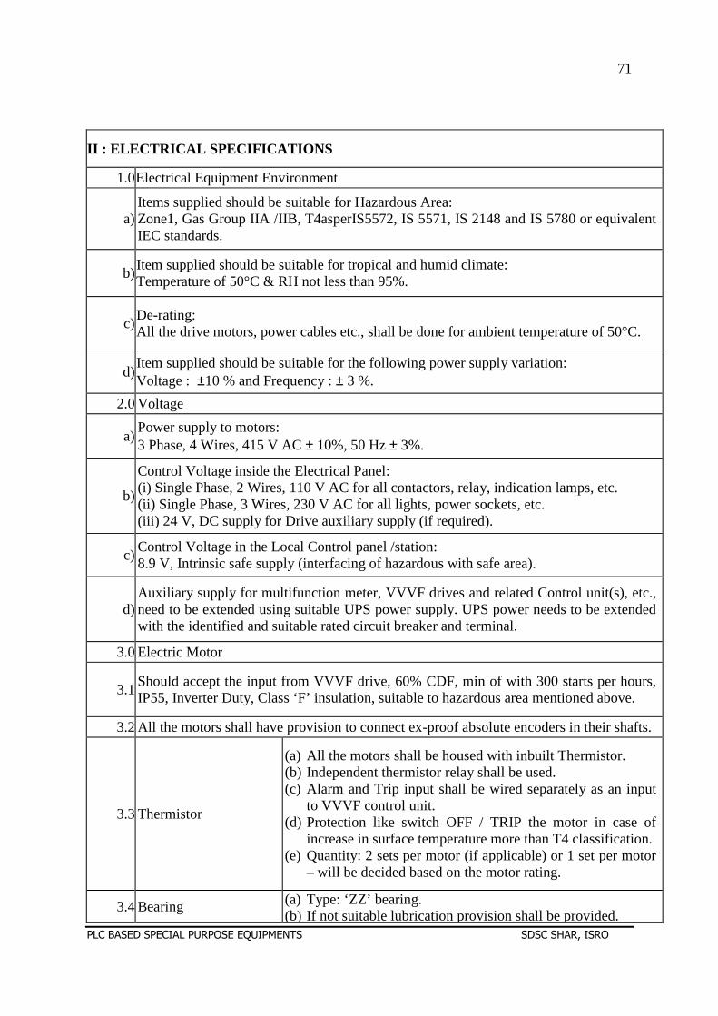
71
PLC BASED SPECIAL PURPOSE EQUIPMENTS SDSC SHAR, ISRO
II : ELECTRICAL SPECIFICATIONS
1.0Electrical Equipment Environment
a)Items supplied should be suitable for Hazardous Area: Zone1, Gas Group IIA /IIB, T4asperIS5572, IS 5571, IS 2148 and IS 5780 or equivalent IEC standards.
b)Item supplied should be suitable for tropical and humid climate: Temperature of 50°C & RH not less than 95%.
c)De-rating: All the drive motors, power cables etc., shall be done for ambient temperature of 50°C.
d)Item supplied should be suitable for the following power supply variation: Voltage : ±10 % and Frequency : ± 3 %.
2.0 Voltage
a)Power supply to motors: 3 Phase, 4 Wires, 415 V AC ± 10%, 50 Hz ± 3%.
b)
Control Voltage inside the Electrical Panel: (i) Single Phase, 2 Wires, 110 V AC for all contactors, relay, indication lamps, etc. (ii) Single Phase, 3 Wires, 230 V AC for all lights, power sockets, etc. (iii) 24 V, DC supply for Drive auxiliary supply (if required).
c)Control Voltage in the Local Control panel /station: 8.9 V, Intrinsic safe supply (interfacing of hazardous with safe area).
d)Auxiliary supply for multifunction meter, VVVF drives and related Control unit(s), etc., need to be extended using suitable UPS power supply. UPS power needs to be extended with the identified and suitable rated circuit breaker and terminal.
3.0 Electric Motor
3.1Should accept the input from VVVF drive, 60% CDF, min of with 300 starts per hours, IP55, Inverter Duty, Class ‘F’ insulation, suitable to hazardous area mentioned above.
3.2 All the motors shall have provision to connect ex-proof absolute encoders in their shafts.
3.3 Thermistor
(a) All the motors shall be housed with inbuilt Thermistor. (b) Independent thermistor relay shall be used. (c) Alarm and Trip input shall be wired separately as an input
to VVVF control unit. (d) Protection like switch OFF / TRIP the motor in case of
increase in surface temperature more than T4 classification. (e) Quantity: 2 sets per motor (if applicable) or 1 set per motor
– will be decided based on the motor rating.
3.4 Bearing (a) Type: ‘ZZ’ bearing. (b) If not suitable lubrication provision shall be provided.
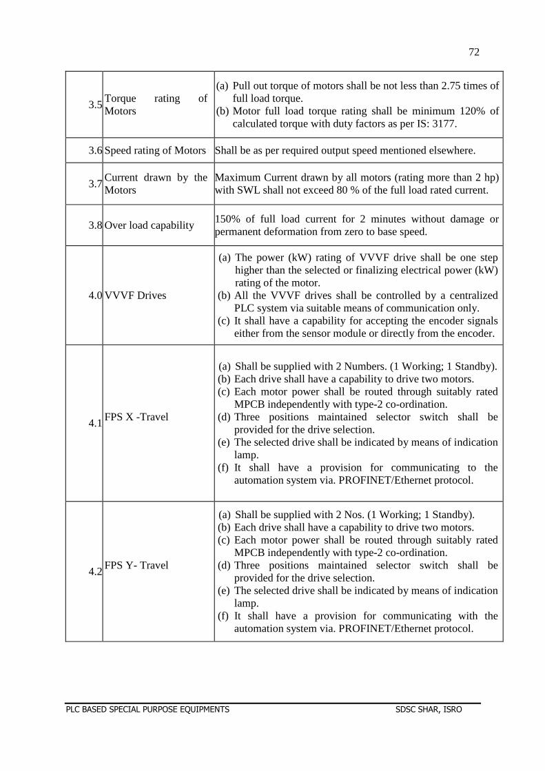
72
PLC BASED SPECIAL PURPOSE EQUIPMENTS SDSC SHAR, ISRO
3.5Torque rating of Motors
(a) Pull out torque of motors shall be not less than 2.75 times of full load torque.
(b) Motor full load torque rating shall be minimum 120% of calculated torque with duty factors as per IS: 3177.
3.6 Speed rating of Motors Shall be as per required output speed mentioned elsewhere.
3.7Current drawn by the Motors
Maximum Current drawn by all motors (rating more than 2 hp) with SWL shall not exceed 80 % of the full load rated current.
3.8 Over load capability 150% of full load current for 2 minutes without damage or permanent deformation from zero to base speed.
4.0 VVVF Drives
(a) The power (kW) rating of VVVF drive shall be one step higher than the selected or finalizing electrical power (kW) rating of the motor.
(b) All the VVVF drives shall be controlled by a centralized PLC system via suitable means of communication only.
(c) It shall have a capability for accepting the encoder signals either from the sensor module or directly from the encoder.
4.1FPS X -Travel
(a) Shall be supplied with 2 Numbers. (1 Working; 1 Standby). (b) Each drive shall have a capability to drive two motors. (c) Each motor power shall be routed through suitably rated
MPCB independently with type-2 co-ordination. (d) Three positions maintained selector switch shall be
provided for the drive selection. (e) The selected drive shall be indicated by means of indication
lamp. (f) It shall have a provision for communicating to the
automation system via. PROFINET/Ethernet protocol.
4.2FPS Y- Travel
(a) Shall be supplied with 2 Nos. (1 Working; 1 Standby). (b) Each drive shall have a capability to drive two motors. (c) Each motor power shall be routed through suitably rated
MPCB independently with type-2 co-ordination. (d) Three positions maintained selector switch shall be
provided for the drive selection. (e) The selected drive shall be indicated by means of indication
lamp. (f) It shall have a provision for communicating with the
automation system via. PROFINET/Ethernet protocol.
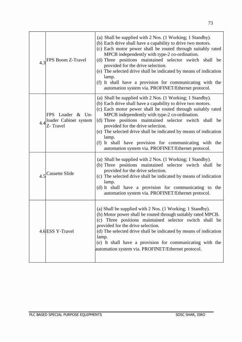
73
PLC BASED SPECIAL PURPOSE EQUIPMENTS SDSC SHAR, ISRO
4.3FPS Boom Z-Travel
(a) Shall be supplied with 2 Nos. (1 Working; 1 Standby). (b) Each drive shall have a capability to drive two motors. (c) Each motor power shall be routed through suitably rated
MPCB independently with type-2 co-ordination. (d) Three positions maintained selector switch shall be
provided for the drive selection. (e) The selected drive shall be indicated by means of indication
lamp. (f) It shall have a provision for communicating with the
automation system via. PROFINET/Ethernet protocol.
4.4
FPS Loader & Un-loader Cabinet system Z- Travel
(a) Shall be supplied with 2 Nos. (1 Working; 1 Standby). (b) Each drive shall have a capability to drive two motors. (c) Each motor power shall be routed through suitably rated
MPCB independently with type-2 co-ordination. (d) Three positions maintained selector switch shall be
provided for the drive selection. (e) The selected drive shall be indicated by means of indication
lamp. (f) It shall have provision for communicating with the
automation system via. PROFINET/Ethernet protocol.
4.5Cassette Slide
(a) Shall be supplied with 2 Nos. (1 Working; 1 Standby). (b) Three positions maintained selector switch shall be
provided for the drive selection. (c) The selected drive shall be indicated by means of indication
lamp. (d) It shall have a provision for communicating to the
automation system via. PROFINET/Ethernet protocol.
4.6 ESS Y-Travel
(a) Shall be supplied with 2 Nos. (1 Working; 1 Standby). (b) Motor power shall be routed through suitably rated MPCB. (c) Three positions maintained selector switch shall be provided for the drive selection. (d) The selected drive shall be indicated by means of indication lamp.
(e) It shall have a provision for communicating with the automation system via. PROFINET/Ethernet protocol.
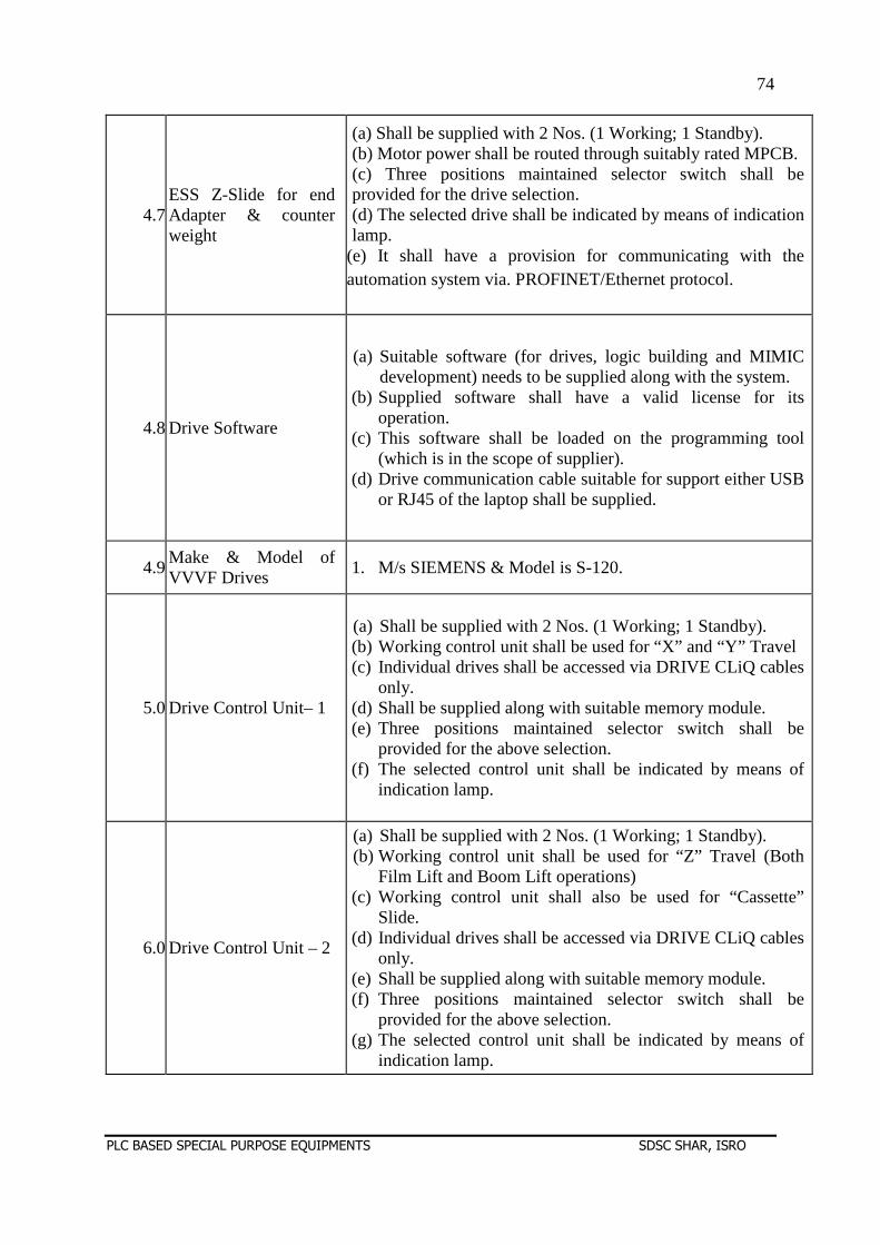
74
PLC BASED SPECIAL PURPOSE EQUIPMENTS SDSC SHAR, ISRO
4.7 ESS Z-Slide for end Adapter & counter weight
(a) Shall be supplied with 2 Nos. (1 Working; 1 Standby). (b) Motor power shall be routed through suitably rated MPCB. (c) Three positions maintained selector switch shall be provided for the drive selection. (d) The selected drive shall be indicated by means of indication lamp.
(e) It shall have a provision for communicating with the automation system via. PROFINET/Ethernet protocol.
4.8 Drive Software
(a) Suitable software (for drives, logic building and MIMIC development) needs to be supplied along with the system.
(b) Supplied software shall have a valid license for its operation.
(c) This software shall be loaded on the programming tool (which is in the scope of supplier).
(d) Drive communication cable suitable for support either USB or RJ45 of the laptop shall be supplied.
4.9Make & Model of VVVF Drives
1. M/s SIEMENS & Model is S-120.
5.0 Drive Control Unit– 1
(a) Shall be supplied with 2 Nos. (1 Working; 1 Standby). (b) Working control unit shall be used for “X” and “Y” Travel (c) Individual drives shall be accessed via DRIVE CLiQ cables
only. (d) Shall be supplied along with suitable memory module. (e) Three positions maintained selector switch shall be
provided for the above selection. (f) The selected control unit shall be indicated by means of
indication lamp.
6.0 Drive Control Unit – 2
(a) Shall be supplied with 2 Nos. (1 Working; 1 Standby). (b) Working control unit shall be used for “Z” Travel (Both
Film Lift and Boom Lift operations) (c) Working control unit shall also be used for “Cassette”
Slide. (d) Individual drives shall be accessed via DRIVE CLiQ cables
only. (e) Shall be supplied along with suitable memory module. (f) Three positions maintained selector switch shall be
provided for the above selection. (g) The selected control unit shall be indicated by means of
indication lamp.
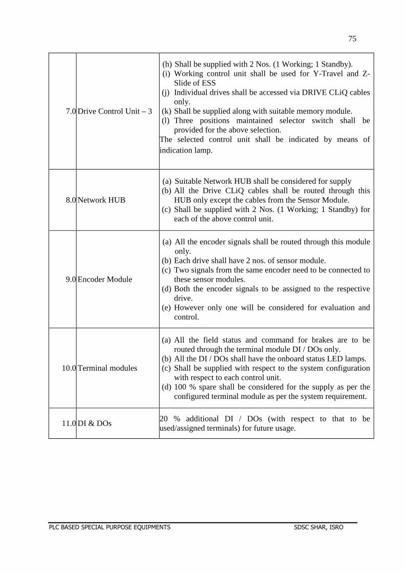
75
PLC BASED SPECIAL PURPOSE EQUIPMENTS SDSC SHAR, ISRO
7.0 Drive Control Unit – 3
(h) Shall be supplied with 2 Nos. (1 Working; 1 Standby). (i) Working control unit shall be used for Y-Travel and Z-
Slide of ESS (j) Individual drives shall be accessed via DRIVE CLiQ cables
only. (k) Shall be supplied along with suitable memory module. (l) Three positions maintained selector switch shall be
provided for the above selection. The selected control unit shall be indicated by means of indication lamp.
8.0 Network HUB
(a) Suitable Network HUB shall be considered for supply (b) All the Drive CLiQ cables shall be routed through this
HUB only except the cables from the Sensor Module. (c) Shall be supplied with 2 Nos. (1 Working; 1 Standby) for
each of the above control unit.
9.0 Encoder Module
(a) All the encoder signals shall be routed through this module only.
(b) Each drive shall have 2 nos. of sensor module. (c) Two signals from the same encoder need to be connected to
these sensor modules. (d) Both the encoder signals to be assigned to the respective
drive. (e) However only one will be considered for evaluation and
control.
10.0 Terminal modules
(a) All the field status and command for brakes are to be routed through the terminal module DI / DOs only.
(b) All the DI / DOs shall have the onboard status LED lamps. (c) Shall be supplied with respect to the system configuration
with respect to each control unit. (d) 100 % spare shall be considered for the supply as per the
configured terminal module as per the system requirement.
11.0 DI & DOs 20 % additional DI / DOs (with respect to that to be used/assigned terminals) for future usage.
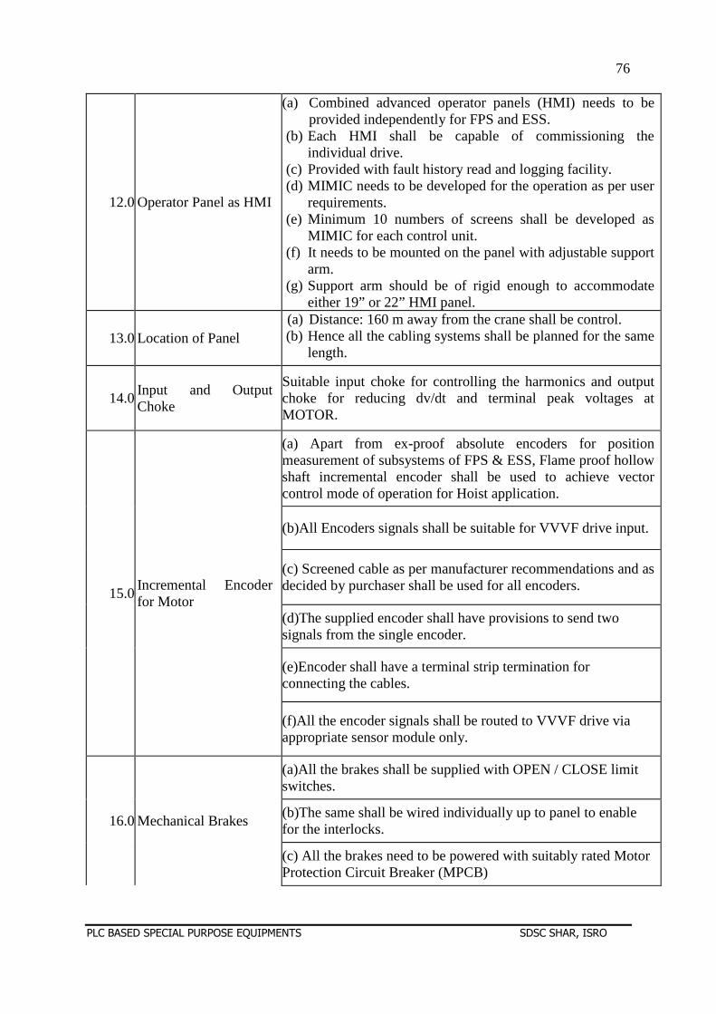
76
PLC BASED SPECIAL PURPOSE EQUIPMENTS SDSC SHAR, ISRO
12.0 Operator Panel as HMI
(a) Combined advanced operator panels (HMI) needs to be provided independently for FPS and ESS.
(b) Each HMI shall be capable of commissioning the individual drive.
(c) Provided with fault history read and logging facility. (d) MIMIC needs to be developed for the operation as per user
requirements. (e) Minimum 10 numbers of screens shall be developed as
MIMIC for each control unit. (f) It needs to be mounted on the panel with adjustable support
arm. (g) Support arm should be of rigid enough to accommodate
either 19” or 22” HMI panel.
13.0 Location of Panel (a) Distance: 160 m away from the crane shall be control. (b) Hence all the cabling systems shall be planned for the same
length.
14.0Input and Output Choke
Suitable input choke for controlling the harmonics and output choke for reducing dv/dt and terminal peak voltages at MOTOR.
15.0Incremental Encoder for Motor
(a) Apart from ex-proof absolute encoders for position measurement of subsystems of FPS & ESS, Flame proof hollow shaft incremental encoder shall be used to achieve vector control mode of operation for Hoist application.
(b)All Encoders signals shall be suitable for VVVF drive input.
(c) Screened cable as per manufacturer recommendations and as decided by purchaser shall be used for all encoders.
(d)The supplied encoder shall have provisions to send two signals from the single encoder.
(e)Encoder shall have a terminal strip termination for connecting the cables.
(f)All the encoder signals shall be routed to VVVF drive via appropriate sensor module only.
16.0 Mechanical Brakes
(a)All the brakes shall be supplied with OPEN / CLOSE limit switches.
(b)The same shall be wired individually up to panel to enable for the interlocks.
(c) All the brakes need to be powered with suitably rated Motor Protection Circuit Breaker (MPCB)
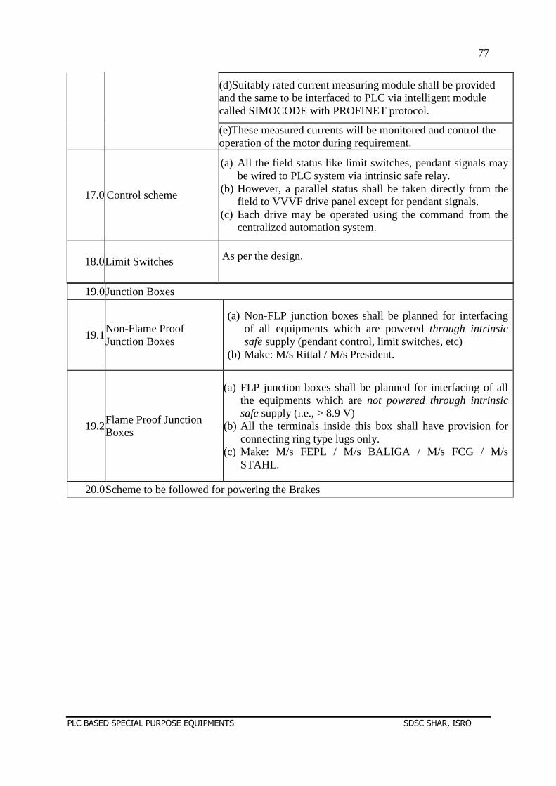
77
PLC BASED SPECIAL PURPOSE EQUIPMENTS SDSC SHAR, ISRO
19.0Junction Boxes
19.1Non-Flame Proof Junction Boxes
(a) Non-FLP junction boxes shall be planned for interfacing of all equipments which are powered through intrinsic safe supply (pendant control, limit switches, etc)
(b) Make: M/s Rittal / M/s President.
19.2Flame Proof Junction Boxes
(a) FLP junction boxes shall be planned for interfacing of all the equipments which are not powered through intrinsic safe supply (i.e., > 8.9 V)
(b) All the terminals inside this box shall have provision for connecting ring type lugs only.
(c) Make: M/s FEPL / M/s BALIGA / M/s FCG / M/s STAHL.
20.0Scheme to be followed for powering the Brakes
(d)Suitably rated current measuring module shall be provided and the same to be interfaced to PLC via intelligent module called SIMOCODE with PROFINET protocol.
(e)These measured currents will be monitored and control the operation of the motor during requirement.
17.0 Control scheme
(a) All the field status like limit switches, pendant signals may be wired to PLC system via intrinsic safe relay.
(b) However, a parallel status shall be taken directly from the field to VVVF drive panel except for pendant signals.
(c) Each drive may be operated using the command from the centralized automation system.
18.0Limit Switches As per the design.
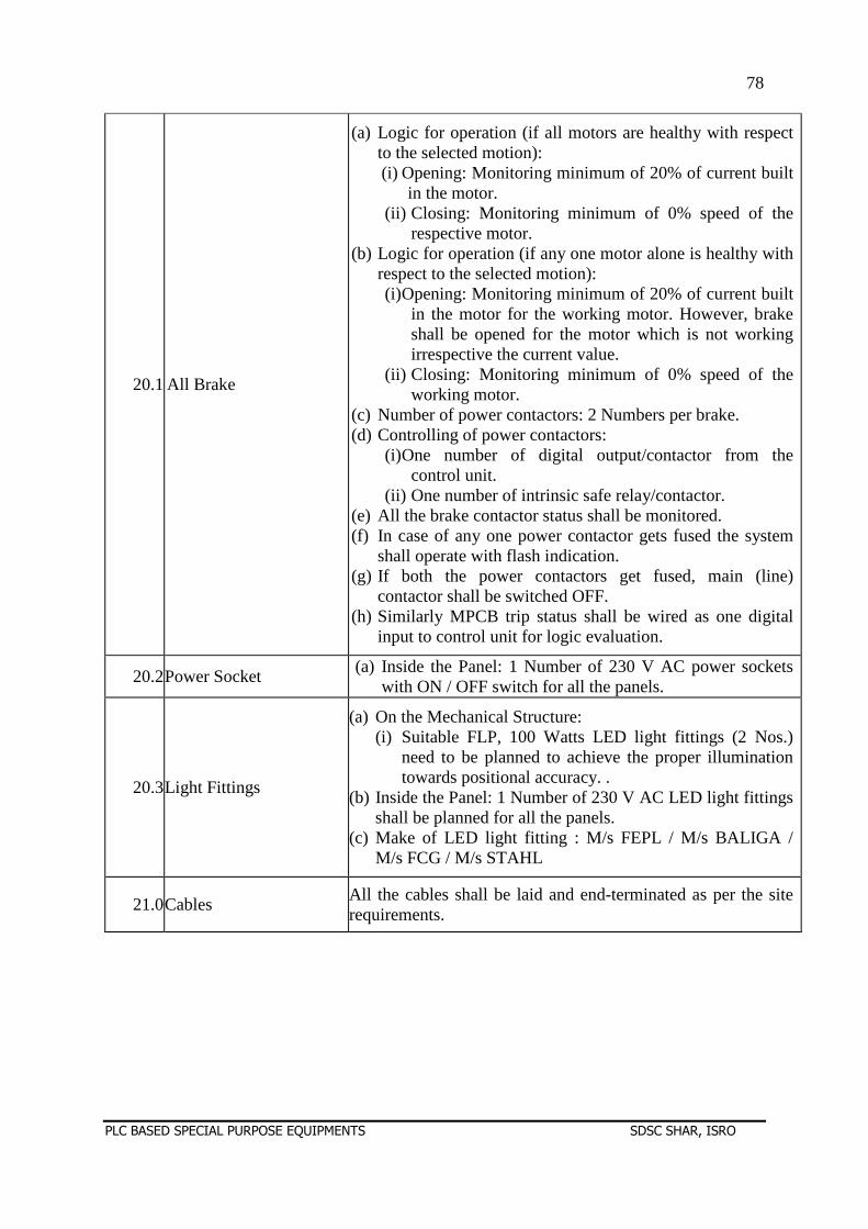
78
PLC BASED SPECIAL PURPOSE EQUIPMENTS SDSC SHAR, ISRO
20.1 All Brake
(a) Logic for operation (if all motors are healthy with respect to the selected motion): (i) Opening: Monitoring minimum of 20% of current built
in the motor. (ii) Closing: Monitoring minimum of 0% speed of the
respective motor. (b) Logic for operation (if any one motor alone is healthy with
respect to the selected motion): (i) Opening: Monitoring minimum of 20% of current built
in the motor for the working motor. However, brake shall be opened for the motor which is not working irrespective the current value.
(ii) Closing: Monitoring minimum of 0% speed of the working motor.
(c) Number of power contactors: 2 Numbers per brake. (d) Controlling of power contactors:
(i) One number of digital output/contactor from the control unit.
(ii) One number of intrinsic safe relay/contactor. (e) All the brake contactor status shall be monitored. (f) In case of any one power contactor gets fused the system
shall operate with flash indication. (g) If both the power contactors get fused, main (line)
contactor shall be switched OFF. (h) Similarly MPCB trip status shall be wired as one digital
input to control unit for logic evaluation.
20.2Power Socket (a) Inside the Panel: 1 Number of 230 V AC power sockets
with ON / OFF switch for all the panels.
20.3Light Fittings
(a) On the Mechanical Structure: (i) Suitable FLP, 100 Watts LED light fittings (2 Nos.)
need to be planned to achieve the proper illumination towards positional accuracy. .
(b) Inside the Panel: 1 Number of 230 V AC LED light fittings shall be planned for all the panels.
(c) Make of LED light fitting : M/s FEPL / M/s BALIGA / M/s FCG / M/s STAHL
21.0Cables All the cables shall be laid and end-terminated as per the site requirements.
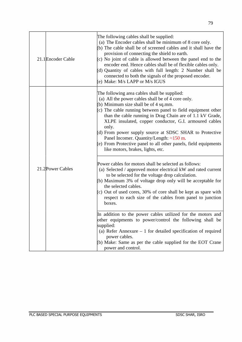
79
PLC BASED SPECIAL PURPOSE EQUIPMENTS SDSC SHAR, ISRO
21.1Encoder Cable
The following cables shall be supplied: (a) The Encoder cables shall be minimum of 8 core only.
(b) The cable shall be of screened cables and it shall have the provision of connecting the shield to earth.
(c) No joint of cable is allowed between the panel end to the encoder end. Hence cables shall be of flexible cables only.
(d) Quantity of cables with full length: 2 Number shall be connected to both the signals of the proposed encoder.
(e) Make: M/s LAPP or M/s IGUS
21.2Power Cables
The following area cables shall be supplied: (a) All the power cables shall be of 4 core only.
(b) Minimum size shall be of 4 sq.mm. (c) The cable running between panel to field equipment other
than the cable running in Drag Chain are of 1.1 kV Grade, XLPE insulated, copper conductor, G.I. armoured cables only.
(d) From power supply source at SDSC SHAR to Protective Panel Incomer. Quantity/Length: ≈150 m.
(e) From Protective panel to all other panels, field equipments like motors, brakes, lights, etc.
Power cables for motors shall be selected as follows: (a) Selected / approved motor electrical kW and rated current
to be selected for the voltage drop calculation. (b) Maximum 3% of voltage drop only will be acceptable for
the selected cables. (c) Out of used cores, 30% of core shall be kept as spare with
respect to each size of the cables from panel to junction boxes.
In addition to the power cables utilized for the motors and other equipments to power/control the following shall be supplied: (a) Refer Annexure – 1 for detailed specification of required
power cables. (b) Make: Same as per the cable supplied for the EOT Crane
power and control.
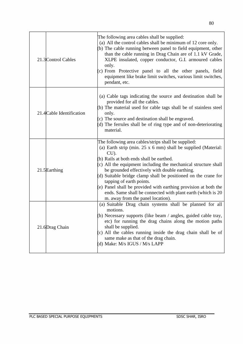
80
PLC BASED SPECIAL PURPOSE EQUIPMENTS SDSC SHAR, ISRO
21.3Control Cables
The following area cables shall be supplied: (a) All the control cables shall be minimum of 12 core only.
(b) The cable running between panel to field equipment, other than the cable running in Drag Chain are of 1.1 kV Grade, XLPE insulated, copper conductor, G.I. armoured cables only.
(c) From Protective panel to all the other panels, field equipment like brake limit switches, various limit switches, pendant, etc.
21.4Cable Identification
(a) Cable tags indicating the source and destination shall be provided for all the cables.
(b) The material used for cable tags shall be of stainless steel only.
(c) The source and destination shall be engraved. (d) The ferrules shall be of ring type and of non-deteriorating
material.
21.5Earthing
The following area cables/strips shall be supplied: (a) Earth strip (min. 25 x 6 mm) shall be supplied (Material:
CU). (b) Rails at both ends shall be earthed. (c) All the equipment including the mechanical structure shall
be grounded effectively with double earthing. (d) Suitable bridge clamp shall be positioned on the crane for
tapping of earth points. (e) Panel shall be provided with earthing provision at both the
ends. Same shall be connected with plant earth (which is 20 m. away from the panel location).
21.6Drag Chain
(a) Suitable Drag chain systems shall be planned for all motions.
(b) Necessary supports (like beam / angles, guided cable tray, etc) for running the drag chains along the motion paths shall be supplied.
(c) All the cables running inside the drag chain shall be of same make as that of the drag chain.
(d) Make: M/s IGUS / M/s LAPP
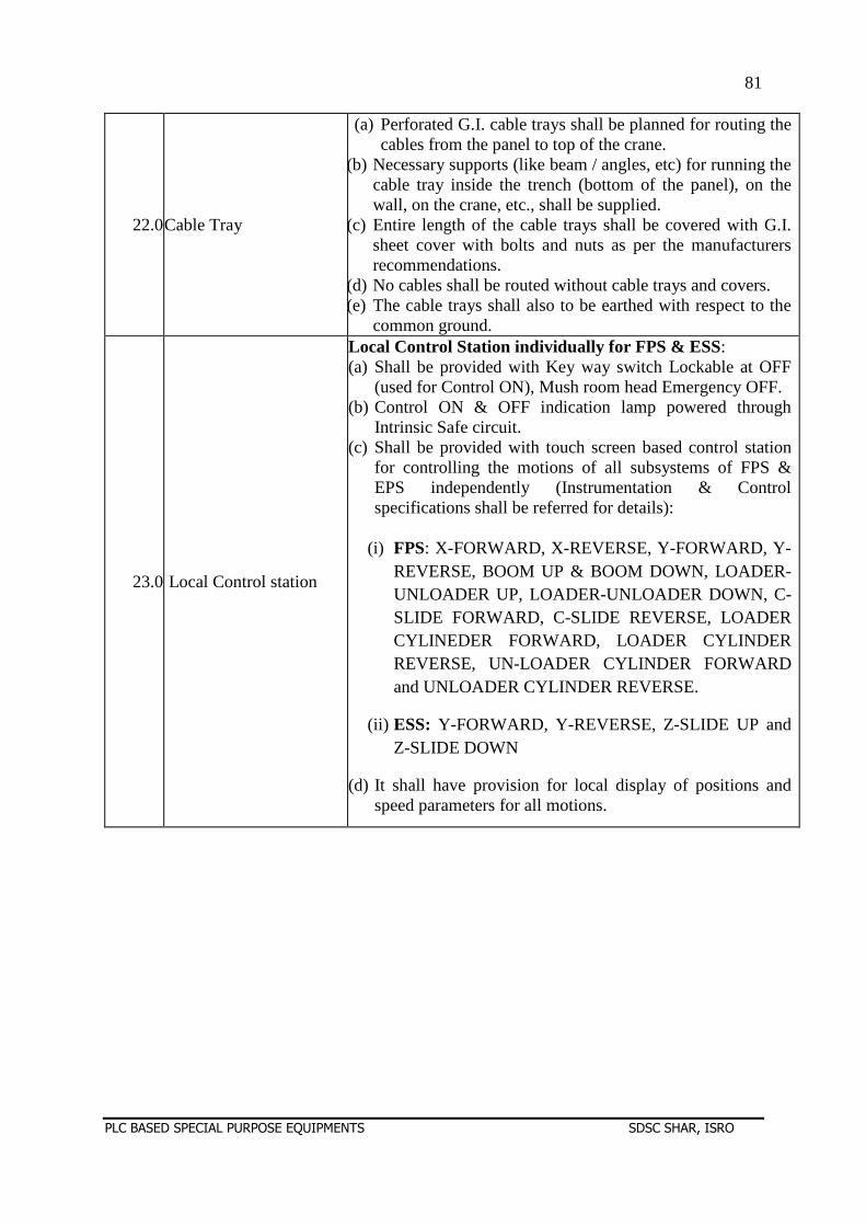
81
PLC BASED SPECIAL PURPOSE EQUIPMENTS SDSC SHAR, ISRO
22.0Cable Tray
(a) Perforated G.I. cable trays shall be planned for routing the cables from the panel to top of the crane.
(b) Necessary supports (like beam / angles, etc) for running the cable tray inside the trench (bottom of the panel), on the wall, on the crane, etc., shall be supplied.
(c) Entire length of the cable trays shall be covered with G.I. sheet cover with bolts and nuts as per the manufacturers recommendations.
(d) No cables shall be routed without cable trays and covers. (e) The cable trays shall also to be earthed with respect to the
common ground.
23.0 Local Control station
Local Control Station individually for FPS & ESS: (a) Shall be provided with Key way switch Lockable at OFF
(used for Control ON), Mush room head Emergency OFF. (b) Control ON & OFF indication lamp powered through
Intrinsic Safe circuit. (c) Shall be provided with touch screen based control station
for controlling the motions of all subsystems of FPS & EPS independently (Instrumentation & Control specifications shall be referred for details):
(i) FPS: X-FORWARD, X-REVERSE, Y-FORWARD, Y-
REVERSE, BOOM UP & BOOM DOWN, LOADER-UNLOADER UP, LOADER-UNLOADER DOWN, C-SLIDE FORWARD, C-SLIDE REVERSE, LOADER CYLINEDER FORWARD, LOADER CYLINDER REVERSE, UN-LOADER CYLINDER FORWARD and UNLOADER CYLINDER REVERSE.
(ii) ESS: Y-FORWARD, Y-REVERSE, Z-SLIDE UP and Z-SLIDE DOWN
(d) It shall have provision for local display of positions and speed parameters for all motions.
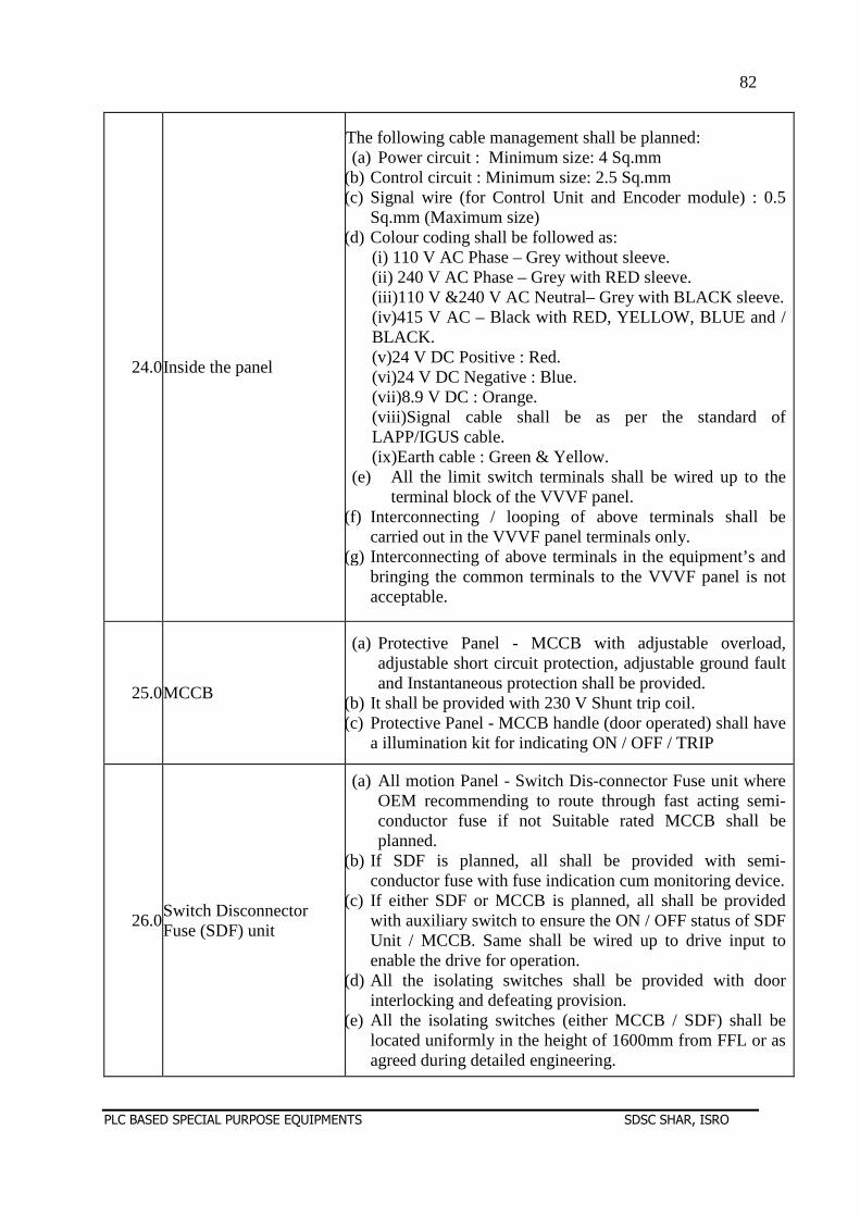
82
PLC BASED SPECIAL PURPOSE EQUIPMENTS SDSC SHAR, ISRO
24.0Inside the panel
The following cable management shall be planned: (a) Power circuit : Minimum size: 4 Sq.mm
(b) Control circuit : Minimum size: 2.5 Sq.mm (c) Signal wire (for Control Unit and Encoder module) : 0.5
Sq.mm (Maximum size) (d) Colour coding shall be followed as:
(i) 110 V AC Phase – Grey without sleeve. (ii) 240 V AC Phase – Grey with RED sleeve. (iii)110 V &240 V AC Neutral– Grey with BLACK sleeve. (iv)415 V AC – Black with RED, YELLOW, BLUE and / BLACK. (v)24 V DC Positive : Red. (vi)24 V DC Negative : Blue. (vii)8.9 V DC : Orange. (viii)Signal cable shall be as per the standard of LAPP/IGUS cable. (ix)Earth cable : Green & Yellow.
(e) All the limit switch terminals shall be wired up to the terminal block of the VVVF panel.
(f) Interconnecting / looping of above terminals shall be carried out in the VVVF panel terminals only.
(g) Interconnecting of above terminals in the equipment’s and bringing the common terminals to the VVVF panel is not acceptable.
25.0MCCB
(a) Protective Panel - MCCB with adjustable overload, adjustable short circuit protection, adjustable ground fault and Instantaneous protection shall be provided.
(b) It shall be provided with 230 V Shunt trip coil. (c) Protective Panel - MCCB handle (door operated) shall have
a illumination kit for indicating ON / OFF / TRIP
26.0Switch Disconnector Fuse (SDF) unit
(a) All motion Panel - Switch Dis-connector Fuse unit where OEM recommending to route through fast acting semi-conductor fuse if not Suitable rated MCCB shall be planned.
(b) If SDF is planned, all shall be provided with semi-conductor fuse with fuse indication cum monitoring device.
(c) If either SDF or MCCB is planned, all shall be provided with auxiliary switch to ensure the ON / OFF status of SDF Unit / MCCB. Same shall be wired up to drive input to enable the drive for operation.
(d) All the isolating switches shall be provided with door interlocking and defeating provision.
(e) All the isolating switches (either MCCB / SDF) shall be located uniformly in the height of 1600mm from FFL or as agreed during detailed engineering.
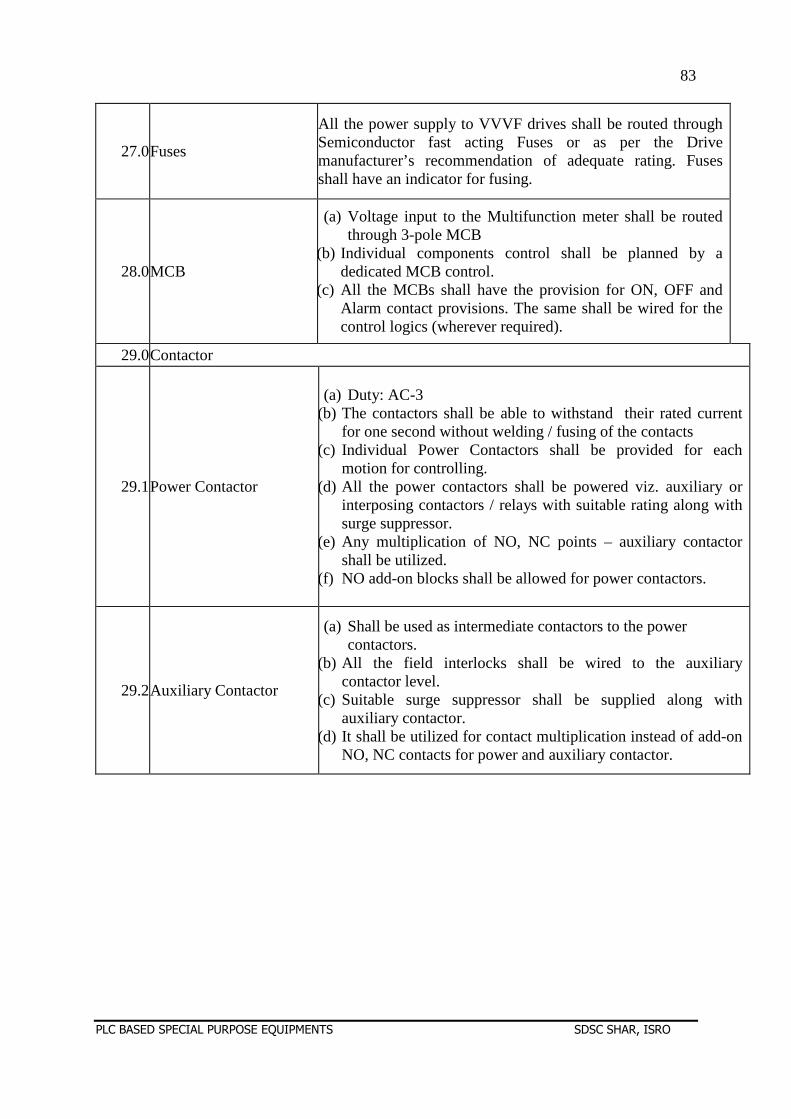
83
PLC BASED SPECIAL PURPOSE EQUIPMENTS SDSC SHAR, ISRO
27.0Fuses
All the power supply to VVVF drives shall be routed through Semiconductor fast acting Fuses or as per the Drive manufacturer’s recommendation of adequate rating. Fuses shall have an indicator for fusing.
28.0MCB
(a) Voltage input to the Multifunction meter shall be routed through 3-pole MCB
(b) Individual components control shall be planned by a dedicated MCB control.
(c) All the MCBs shall have the provision for ON, OFF and Alarm contact provisions. The same shall be wired for the control logics (wherever required).
29.0Contactor
29.1Power Contactor
(a) Duty: AC-3 (b) The contactors shall be able to withstand their rated current
for one second without welding / fusing of the contacts (c) Individual Power Contactors shall be provided for each
motion for controlling. (d) All the power contactors shall be powered viz. auxiliary or
interposing contactors / relays with suitable rating along with surge suppressor.
(e) Any multiplication of NO, NC points – auxiliary contactor shall be utilized.
(f) NO add-on blocks shall be allowed for power contactors.
29.2Auxiliary Contactor
(a) Shall be used as intermediate contactors to the power contactors.
(b) All the field interlocks shall be wired to the auxiliary contactor level.
(c) Suitable surge suppressor shall be supplied along with auxiliary contactor.
(d) It shall be utilized for contact multiplication instead of add-on NO, NC contacts for power and auxiliary contactor.
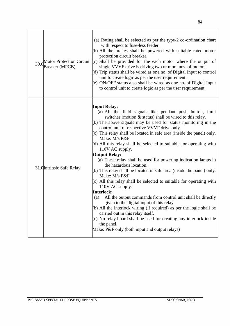
84
PLC BASED SPECIAL PURPOSE EQUIPMENTS SDSC SHAR, ISRO
30.0Motor Protection Circuit Breaker (MPCB)
(a) Rating shall be selected as per the type-2 co-ordination chart with respect to fuse-less feeder.
(b) All the brakes shall be powered with suitable rated motor protection circuit breaker.
(c) Shall be provided for the each motor where the output of single VVVF drive is driving two or more nos. of motors.
(d) Trip status shall be wired as one no. of Digital Input to control unit to create logic as per the user requirement.
(e) ON/OFF status also shall be wired as one no. of Digital Input to control unit to create logic as per the user requirement.
31.0Intrinsic Safe Relay
Input Relay: (a) All the field signals like pendant push button, limit
switches (motion & status) shall be wired to this relay. (b) The above signals may be used for status monitoring in the
control unit of respective VVVF drive only. (c) This relay shall be located in safe area (inside the panel) only.
Make: M/s P&F (d) All this relay shall be selected to suitable for operating with
110V AC supply. Output Relay:
(a) These relay shall be used for powering indication lamps in the hazardous location.
(b) This relay shall be located in safe area (inside the panel) only. Make: M/s P&F
(c) All this relay shall be selected to suitable for operating with 110V AC supply.
Interlock: (a) All the output commands from control unit shall be directly
given to the digital input of this relay. (b) All the interlock wiring (if required) as per the logic shall be
carried out in this relay itself. (c) No relay board shall be used for creating any interlock inside
the panel. Make: P&F only (both input and output relays)
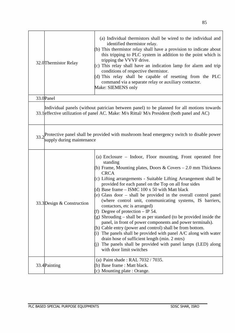
85
PLC BASED SPECIAL PURPOSE EQUIPMENTS SDSC SHAR, ISRO
32.0Thermistor Relay
(a) Individual thermistors shall be wired to the individual and identified thermistor relay.
(b) This thermistor relay shall have a provision to indicate about this tripping to PLC system in addition to the point which is tripping the VVVF drive.
(c) This relay shall have an indication lamp for alarm and trip conditions of respective thermistor.
(d) This relay shall be capable of resetting from the PLC command via a separate relay or auxiliary contactor.
Make: SIEMENS only
33.0Panel
33.1Individual panels (without patrician between panel) to be planned for all motions towards effective utilization of panel AC. Make: M/s Rittal/ M/s President (both panel and AC)
33.2Protective panel shall be provided with mushroom head emergency switch to disable power supply during maintenance
33.3Design & Construction
(a) Enclosure – Indoor, Floor mounting, Front operated free standing
(b) Frame, Mounting plates, Doors & Covers – 2.0 mm Thickness CRCA
(c) Lifting arrangements - Suitable Lifting Arrangement shall be provided for each panel on the Top on all four sides
(d) Base frame – ISMC 100 x 50 with Matt black (e) Glass door – shall be provided in the overall control panel
(where control unit, communicating systems, IS barriers, contactors, etc is arranged)
(f) Degree of protection – IP 54. (g) Shrouding – shall be as per standard (to be provided inside the
panel, in front of power components and power terminals). (h) Cable entry (power and control) shall be from bottom. (i) The panels shall be provided with panel A/C along with water
drain hose of sufficient length (min. 2 mtrs) (j) The panels shall be provided with panel lamps (LED) along
with door limit switches
33.4Painting (a) Paint shade : RAL 7032 / 7035.
(b) Base frame : Matt black. (c) Mounting plate : Orange.
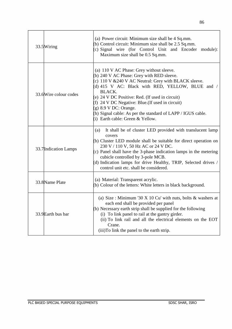
86
PLC BASED SPECIAL PURPOSE EQUIPMENTS SDSC SHAR, ISRO
33.5Wiring
(a) Power circuit: Minimum size shall be 4 Sq.mm. (b) Control circuit: Minimum size shall be 2.5 Sq.mm. (c) Signal wire (for Control Unit and Encoder module):
Maximum size shall be 0.5 Sq.mm.
33.6Wire colour codes
(a) 110 V AC Phase: Grey without sleeve. (b) 240 V AC Phase: Grey with RED sleeve. (c) 110 V &240 V AC Neutral: Grey with BLACK sleeve. (d) 415 V AC: Black with RED, YELLOW, BLUE and /
BLACK. (e) 24 V DC Positive: Red. (If used in circuit) (f) 24 V DC Negative: Blue.(If used in circuit) (g) 8.9 V DC: Orange. (h) Signal cable: As per the standard of LAPP / IGUS cable. (i) Earth cable: Green & Yellow.
33.7Indication Lamps
(a) It shall be of cluster LED provided with translucent lamp covers
(b) Cluster LED module shall be suitable for direct operation on 230 V / 110 V, 50 Hz AC or 24 V DC.
(c) Panel shall have the 3-phase indication lamps in the metering cubicle controlled by 3-pole MCB.
(d) Indication lamps for drive Healthy, TRIP, Selected drives / control unit etc. shall be considered.
33.8Name Plate (a) Material: Transparent acrylic.
(b) Colour of the letters: White letters in black background.
33.9Earth bus bar
(a) Size : Minimum '30 X 10 Cu' with nuts, bolts & washers at each end shall be provided per panel
(b) Necessary earth strip shall be supplied for the following (i) To link panel to rail at the gantry girder. (ii) To link rail and all the electrical elements on the EOT
Crane. (iii)To link the panel to the earth strip.
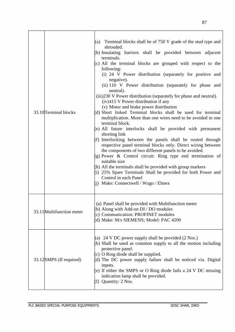
87
PLC BASED SPECIAL PURPOSE EQUIPMENTS SDSC SHAR, ISRO
33.10Terminal blocks
(a) Terminal blocks shall be of 750 V grade of the stud type and shrouded.
(b) Insulating barriers shall be provided between adjacent terminals.
(c) All the terminal blocks are grouped with respect to the following: (i) 24 V Power distribution (separately for positive and
negative). (ii) 110 V Power distribution (separately for phase and
neutral). (iii)230 V Power distribution (separately for phase and neutral).
(iv) 415 V Power distribution if any (v) Motor and brake power distribution
(d) Short linked Terminal blocks shall be used for terminal multiplication. More than one wires need to be avoided in one terminal block.
(e) All future interlocks shall be provided with permanent shorting link
(f) Interlocking between the panels shall be routed through respective panel terminal blocks only. Direct wiring between the components of two different panels to be avoided.
(g) Power & Control circuit: Ring type end termination of suitable size
(h) All the terminals shall be provided with group markers (i) 25% Spare Terminals Shall be provided for both Power and
Control in each Panel (j) Make: Connectwell / Wago / Elmex
33.11Multifunction meter
(a) Panel shall be provided with Multifunction meter (b) Along with Add-on DI / DO modules (c) Communication: PROFINET modules (d) Make: M/s SIEMENS; Model: PAC 4200
33.12SMPS (If required)
(a) 24 V DC power supply shall be provided (2 Nos.) (b) Shall be used as common supply to all the motion including
protective panel. (c) O Ring diode shall be supplied. (d) The DC power supply failure shall be noticed via. Digital
inputs. (e) If either the SMPS or O Ring diode fails a 24 V DC missing
indication lamp shall be provided. (f) Quantity: 2 Nos.
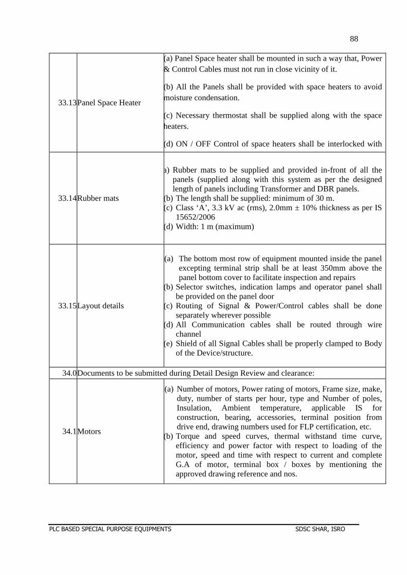
88
PLC BASED SPECIAL PURPOSE EQUIPMENTS SDSC SHAR, ISRO
33.13Panel Space Heater
(a) Panel Space heater shall be mounted in such a way that, Power & Control Cables must not run in close vicinity of it.
(b) All the Panels shall be provided with space heaters to avoid moisture condensation.
(c) Necessary thermostat shall be supplied along with the space heaters.
(d) ON / OFF Control of space heaters shall be interlocked with main contactor. i.e., whenever main contactor is in OFF condition,
33.14Rubber mats
(a) Rubber mats to be supplied and provided in-front of all the panels (supplied along with this system as per the designed length of panels including Transformer and DBR panels.
(b) The length shall be supplied: minimum of 30 m. (c) Class ‘A’, 3.3 kV ac (rms), 2.0mm ± 10% thickness as per IS
15652/2006 (d) Width: 1 m (maximum)
33.15Layout details
(a) The bottom most row of equipment mounted inside the panel excepting terminal strip shall be at least 350mm above the panel bottom cover to facilitate inspection and repairs
(b) Selector switches, indication lamps and operator panel shall be provided on the panel door
(c) Routing of Signal & Power/Control cables shall be done separately wherever possible
(d) All Communication cables shall be routed through wire channel
(e) Shield of all Signal Cables shall be properly clamped to Body of the Device/structure.
34.0Documents to be submitted during Detail Design Review and clearance:
34.1Motors
(a) Number of motors, Power rating of motors, Frame size, make, duty, number of starts per hour, type and Number of poles, Insulation, Ambient temperature, applicable IS for construction, bearing, accessories, terminal position from drive end, drawing numbers used for FLP certification, etc.
(b) Torque and speed curves, thermal withstand time curve, efficiency and power factor with respect to loading of the motor, speed and time with respect to current and complete G.A of motor, terminal box / boxes by mentioning the approved drawing reference and nos.
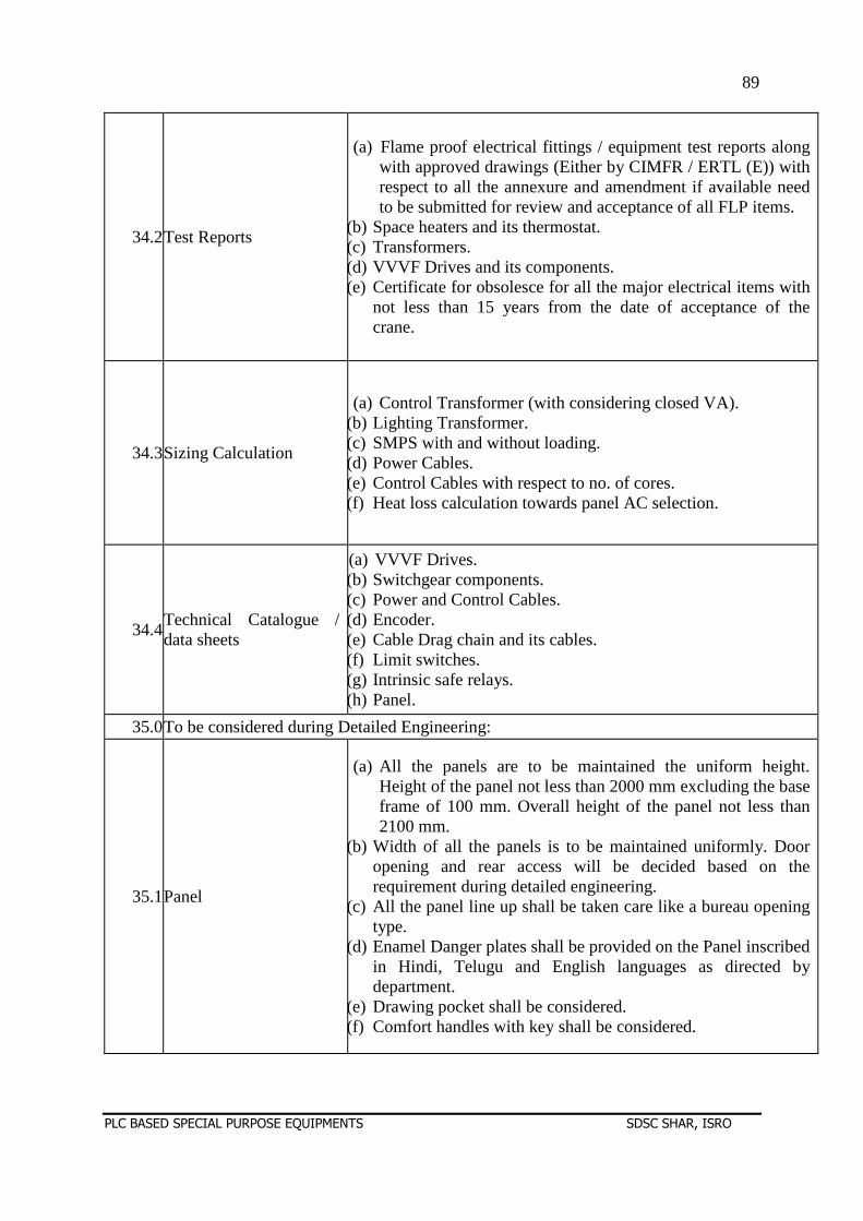
89
PLC BASED SPECIAL PURPOSE EQUIPMENTS SDSC SHAR, ISRO
34.2Test Reports
(a) Flame proof electrical fittings / equipment test reports along with approved drawings (Either by CIMFR / ERTL (E)) with respect to all the annexure and amendment if available need to be submitted for review and acceptance of all FLP items.
(b) Space heaters and its thermostat. (c) Transformers. (d) VVVF Drives and its components. (e) Certificate for obsolesce for all the major electrical items with
not less than 15 years from the date of acceptance of the crane.
34.3Sizing Calculation
(a) Control Transformer (with considering closed VA). (b) Lighting Transformer. (c) SMPS with and without loading. (d) Power Cables. (e) Control Cables with respect to no. of cores. (f) Heat loss calculation towards panel AC selection.
34.4Technical Catalogue / data sheets
(a) VVVF Drives. (b) Switchgear components. (c) Power and Control Cables. (d) Encoder. (e) Cable Drag chain and its cables. (f) Limit switches. (g) Intrinsic safe relays. (h) Panel.
35.0To be considered during Detailed Engineering:
35.1Panel
(a) All the panels are to be maintained the uniform height. Height of the panel not less than 2000 mm excluding the base frame of 100 mm. Overall height of the panel not less than 2100 mm.
(b) Width of all the panels is to be maintained uniformly. Door opening and rear access will be decided based on the requirement during detailed engineering.
(c) All the panel line up shall be taken care like a bureau opening type.
(d) Enamel Danger plates shall be provided on the Panel inscribed in Hindi, Telugu and English languages as directed by department.
(e) Drawing pocket shall be considered. (f) Comfort handles with key shall be considered.
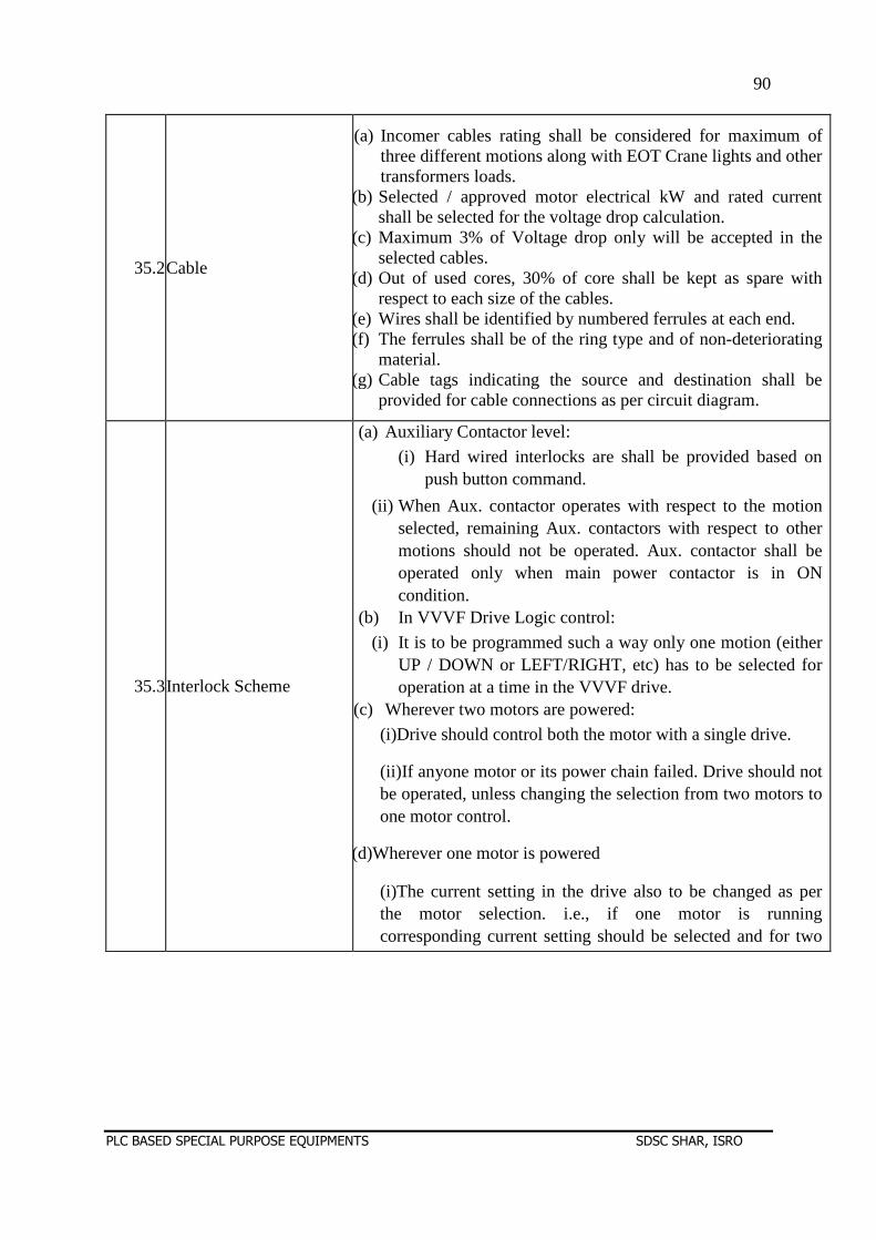
90
PLC BASED SPECIAL PURPOSE EQUIPMENTS SDSC SHAR, ISRO
35.2Cable
(a) Incomer cables rating shall be considered for maximum of three different motions along with EOT Crane lights and other transformers loads.
(b) Selected / approved motor electrical kW and rated current shall be selected for the voltage drop calculation.
(c) Maximum 3% of Voltage drop only will be accepted in the selected cables.
(d) Out of used cores, 30% of core shall be kept as spare with respect to each size of the cables.
(e) Wires shall be identified by numbered ferrules at each end. (f) The ferrules shall be of the ring type and of non-deteriorating
material. (g) Cable tags indicating the source and destination shall be
provided for cable connections as per circuit diagram.
35.3Interlock Scheme
(a) Auxiliary Contactor level:
(i) Hard wired interlocks are shall be provided based on push button command.
(ii) When Aux. contactor operates with respect to the motion selected, remaining Aux. contactors with respect to other motions should not be operated. Aux. contactor shall be operated only when main power contactor is in ON condition.
(b) In VVVF Drive Logic control:
(i) It is to be programmed such a way only one motion (either UP / DOWN or LEFT/RIGHT, etc) has to be selected for operation at a time in the VVVF drive.
(c) Wherever two motors are powered:
(i)Drive should control both the motor with a single drive.
(ii)If anyone motor or its power chain failed. Drive should not be operated, unless changing the selection from two motors to one motor control.
(d)Wherever one motor is powered
(i)The current setting in the drive also to be changed as per the motor selection. i.e., if one motor is running corresponding current setting should be selected and for two motors, etc.
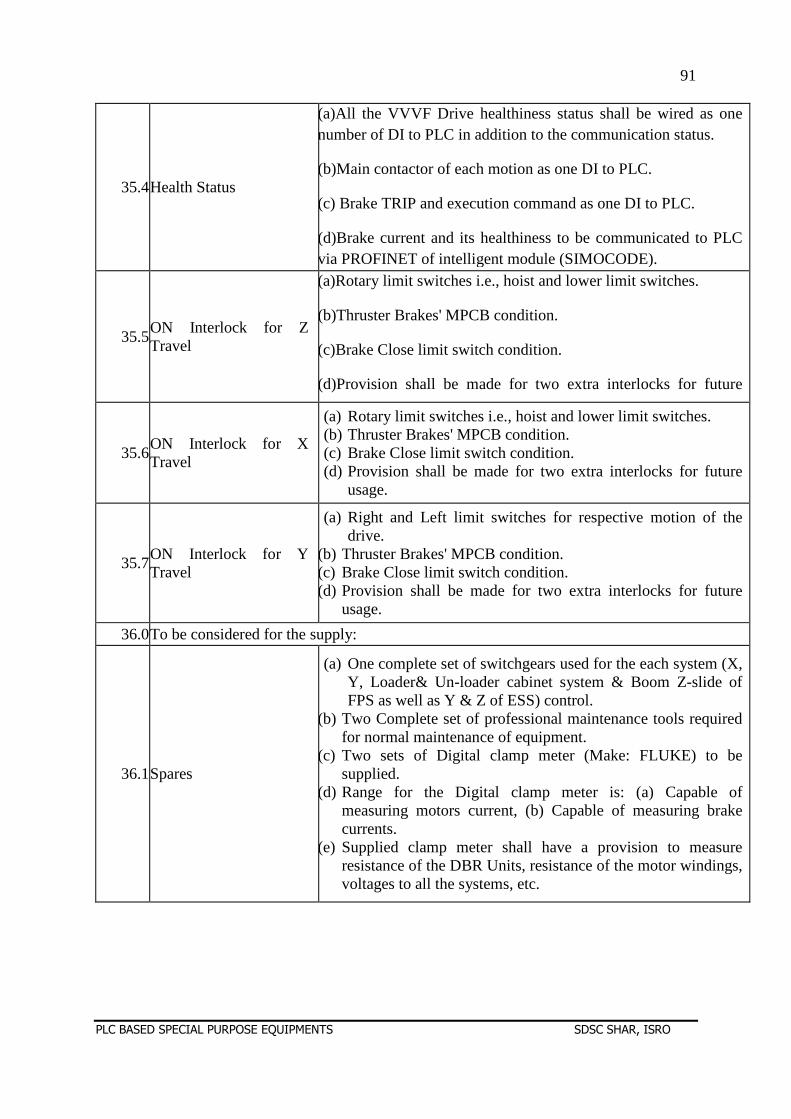
91
PLC BASED SPECIAL PURPOSE EQUIPMENTS SDSC SHAR, ISRO
35.4Health Status
(a)All the VVVF Drive healthiness status shall be wired as one number of DI to PLC in addition to the communication status.
(b)Main contactor of each motion as one DI to PLC.
(c) Brake TRIP and execution command as one DI to PLC.
(d)Brake current and its healthiness to be communicated to PLC via PROFINET of intelligent module (SIMOCODE).
35.5ON Interlock for Z Travel
(a)Rotary limit switches i.e., hoist and lower limit switches.
(b)Thruster Brakes' MPCB condition.
(c)Brake Close limit switch condition.
(d)Provision shall be made for two extra interlocks for future usage.
35.6ON Interlock for X Travel
(a) Rotary limit switches i.e., hoist and lower limit switches. (b) Thruster Brakes' MPCB condition. (c) Brake Close limit switch condition. (d) Provision shall be made for two extra interlocks for future
usage.
35.7ON Interlock for Y Travel
(a) Right and Left limit switches for respective motion of the drive.
(b) Thruster Brakes' MPCB condition. (c) Brake Close limit switch condition. (d) Provision shall be made for two extra interlocks for future
usage.
36.0To be considered for the supply:
36.1Spares
(a) One complete set of switchgears used for the each system (X, Y, Loader& Un-loader cabinet system & Boom Z-slide of FPS as well as Y & Z of ESS) control.
(b) Two Complete set of professional maintenance tools required for normal maintenance of equipment.
(c) Two sets of Digital clamp meter (Make: FLUKE) to be supplied.
(d) Range for the Digital clamp meter is: (a) Capable of measuring motors current, (b) Capable of measuring brake currents.
(e) Supplied clamp meter shall have a provision to measure resistance of the DBR Units, resistance of the motor windings, voltages to all the systems, etc.
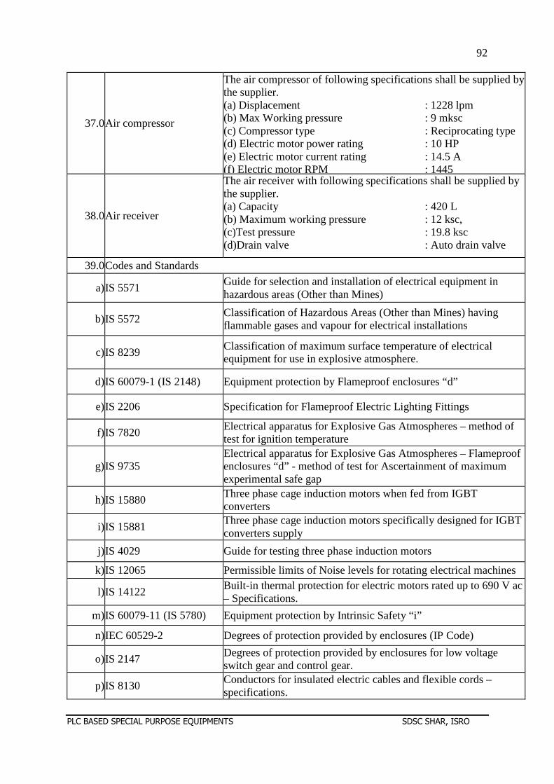
92
PLC BASED SPECIAL PURPOSE EQUIPMENTS SDSC SHAR, ISRO
37.0Air compressor
The air compressor of following specifications shall be supplied by the supplier. (a) Displacement : 1228 lpm (b) Max Working pressure : 9 mksc (c) Compressor type : Reciprocating type (d) Electric motor power rating : 10 HP (e) Electric motor current rating : 14.5 A (f) Electric motor RPM : 1445
38.0Air receiver
The air receiver with following specifications shall be supplied by the supplier. (a) Capacity : 420 L (b) Maximum working pressure : 12 ksc, (c)Test pressure : 19.8 ksc (d)Drain valve : Auto drain valve
39.0Codes and Standards
a)IS 5571 Guide for selection and installation of electrical equipment in hazardous areas (Other than Mines)
b)IS 5572 Classification of Hazardous Areas (Other than Mines) having flammable gases and vapour for electrical installations
c)IS 8239 Classification of maximum surface temperature of electrical equipment for use in explosive atmosphere.
d)IS 60079-1 (IS 2148) Equipment protection by Flameproof enclosures “d”
e)IS 2206 Specification for Flameproof Electric Lighting Fittings
f)IS 7820 Electrical apparatus for Explosive Gas Atmospheres – method of test for ignition temperature
g)IS 9735 Electrical apparatus for Explosive Gas Atmospheres – Flameproof enclosures “d” - method of test for Ascertainment of maximum experimental safe gap
h)IS 15880 Three phase cage induction motors when fed from IGBT converters
i)IS 15881 Three phase cage induction motors specifically designed for IGBT converters supply
j)IS 4029 Guide for testing three phase induction motors
k)IS 12065 Permissible limits of Noise levels for rotating electrical machines
l)IS 14122 Built-in thermal protection for electric motors rated up to 690 V ac – Specifications.
m)IS 60079-11 (IS 5780) Equipment protection by Intrinsic Safety “i”
n)IEC 60529-2 Degrees of protection provided by enclosures (IP Code)
o)IS 2147 Degrees of protection provided by enclosures for low voltage switch gear and control gear.
p)IS 8130 Conductors for insulated electric cables and flexible cords – specifications.
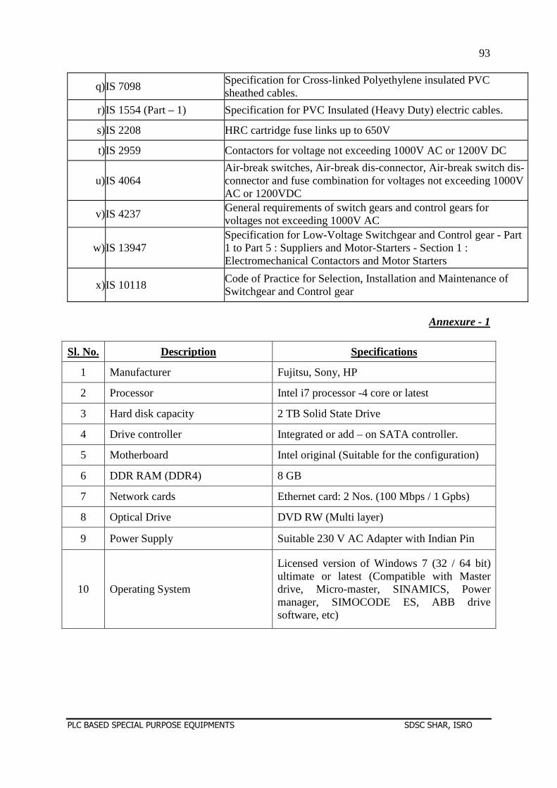
93
PLC BASED SPECIAL PURPOSE EQUIPMENTS SDSC SHAR, ISRO
q)IS 7098 Specification for Cross-linked Polyethylene insulated PVC sheathed cables.
r)IS 1554 (Part – 1) Specification for PVC Insulated (Heavy Duty) electric cables.
s)IS 2208 HRC cartridge fuse links up to 650V
t)IS 2959 Contactors for voltage not exceeding 1000V AC or 1200V DC
u)IS 4064 Air-break switches, Air-break dis-connector, Air-break switch dis-connector and fuse combination for voltages not exceeding 1000V AC or 1200VDC
v)IS 4237 General requirements of switch gears and control gears for voltages not exceeding 1000V AC
w)IS 13947 Specification for Low-Voltage Switchgear and Control gear - Part 1 to Part 5 : Suppliers and Motor-Starters - Section 1 : Electromechanical Contactors and Motor Starters
x)IS 10118 Code of Practice for Selection, Installation and Maintenance of Switchgear and Control gear
Annexure - 1
Sl. No. Description Specifications
1 Manufacturer Fujitsu, Sony, HP
2 Processor Intel i7 processor -4 core or latest
3 Hard disk capacity 2 TB Solid State Drive
4 Drive controller Integrated or add – on SATA controller.
5 Motherboard Intel original (Suitable for the configuration)
6 DDR RAM (DDR4) 8 GB
7 Network cards Ethernet card: 2 Nos. (100 Mbps / 1 Gpbs)
8 Optical Drive DVD RW (Multi layer)
9 Power Supply Suitable 230 V AC Adapter with Indian Pin
10 Operating System
Licensed version of Windows 7 (32 / 64 bit) ultimate or latest (Compatible with Master drive, Micro-master, SINAMICS, Power manager, SIMOCODE ES, ABB drive software, etc)
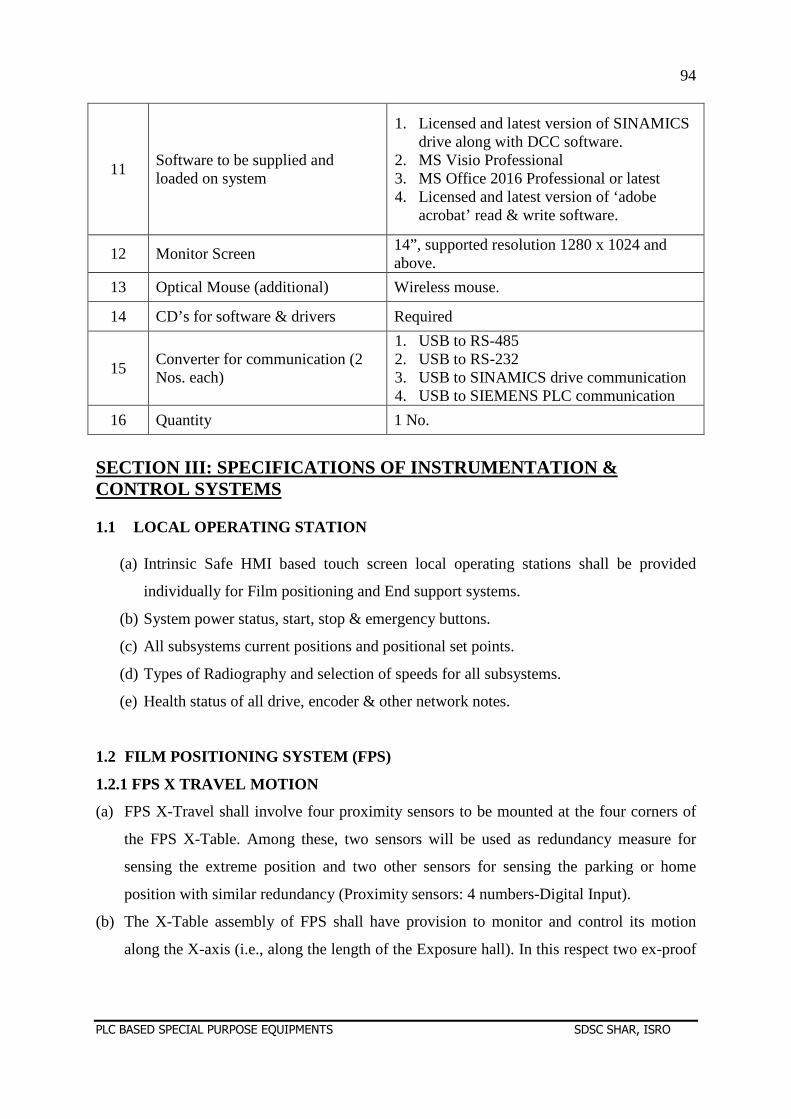
94
PLC BASED SPECIAL PURPOSE EQUIPMENTS SDSC SHAR, ISRO
11 Software to be supplied and loaded on system
1. Licensed and latest version of SINAMICS drive along with DCC software.
2. MS Visio Professional 3. MS Office 2016 Professional or latest 4. Licensed and latest version of ‘adobe
acrobat’ read & write software.
12 Monitor Screen 14”, supported resolution 1280 x 1024 and above.
13 Optical Mouse (additional) Wireless mouse.
14 CD’s for software & drivers Required
15 Converter for communication (2 Nos. each)
1. USB to RS-485 2. USB to RS-232 3. USB to SINAMICS drive communication 4. USB to SIEMENS PLC communication
16 Quantity 1 No.
SECTION III: SPECIFICATIONS OF INSTRUMENTATION & CONTROL SYSTEMS 1.1 LOCAL OPERATING STATION
(a) Intrinsic Safe HMI based touch screen local operating stations shall be provided
individually for Film positioning and End support systems.
(b) System power status, start, stop & emergency buttons.
(c) All subsystems current positions and positional set points.
(d) Types of Radiography and selection of speeds for all subsystems.
(e) Health status of all drive, encoder & other network notes.
1.2 FILM POSITIONING SYSTEM (FPS)
1.2.1 FPS X TRAVEL MOTION
(a) FPS X-Travel shall involve four proximity sensors to be mounted at the four corners of
the FPS X-Table. Among these, two sensors will be used as redundancy measure for
sensing the extreme position and two other sensors for sensing the parking or home
position with similar redundancy (Proximity sensors: 4 numbers-Digital Input).
(b) The X-Table assembly of FPS shall have provision to monitor and control its motion
along the X-axis (i.e., along the length of the Exposure hall). In this respect two ex-proof
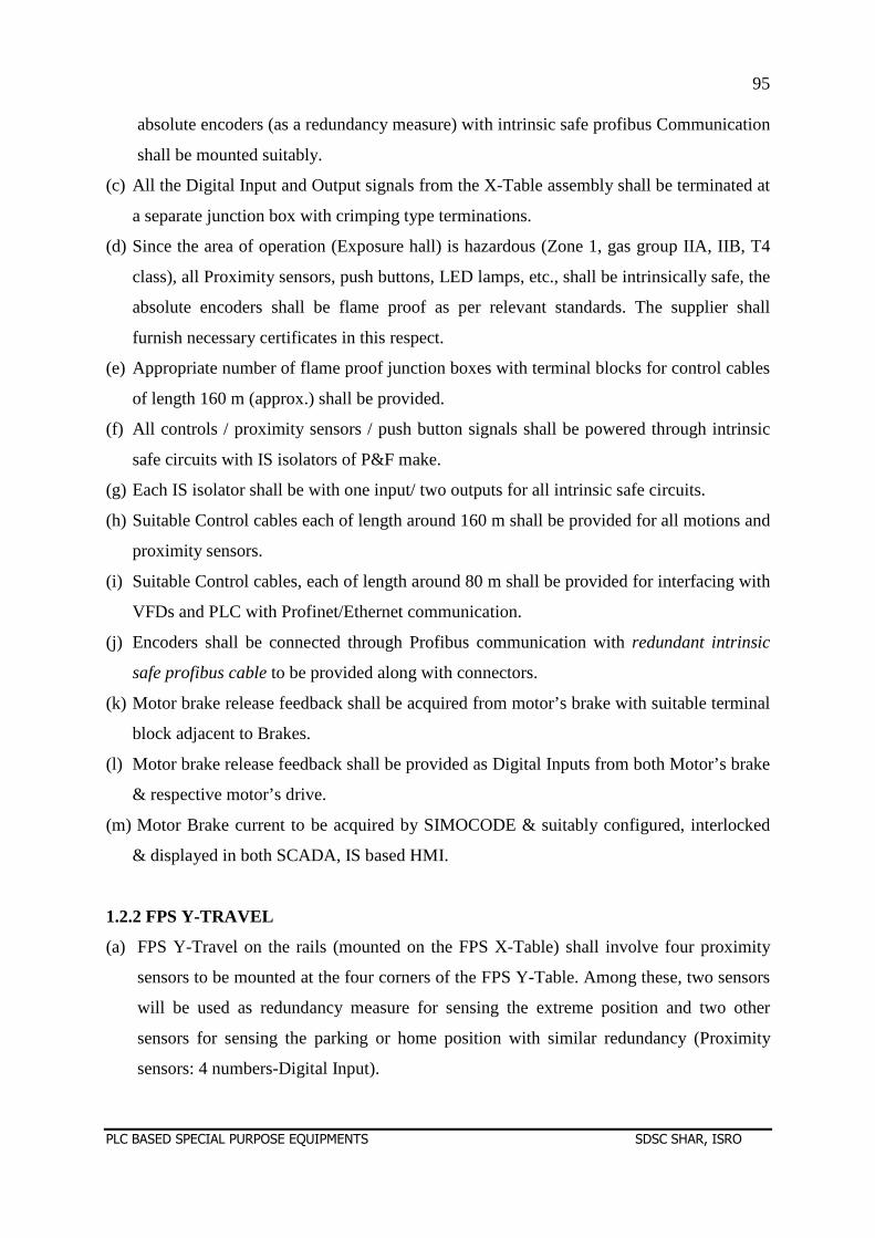
95
PLC BASED SPECIAL PURPOSE EQUIPMENTS SDSC SHAR, ISRO
absolute encoders (as a redundancy measure) with intrinsic safe profibus Communication
shall be mounted suitably.
(c) All the Digital Input and Output signals from the X-Table assembly shall be terminated at
a separate junction box with crimping type terminations.
(d) Since the area of operation (Exposure hall) is hazardous (Zone 1, gas group IIA, IIB, T4
class), all Proximity sensors, push buttons, LED lamps, etc., shall be intrinsically safe, the
absolute encoders shall be flame proof as per relevant standards. The supplier shall
furnish necessary certificates in this respect.
(e) Appropriate number of flame proof junction boxes with terminal blocks for control cables
of length 160 m (approx.) shall be provided.
(f) All controls / proximity sensors / push button signals shall be powered through intrinsic
safe circuits with IS isolators of P&F make.
(g) Each IS isolator shall be with one input/ two outputs for all intrinsic safe circuits.
(h) Suitable Control cables each of length around 160 m shall be provided for all motions and
proximity sensors.
(i) Suitable Control cables, each of length around 80 m shall be provided for interfacing with
VFDs and PLC with Profinet/Ethernet communication.
(j) Encoders shall be connected through Profibus communication with redundant intrinsic
safe profibus cable to be provided along with connectors.
(k) Motor brake release feedback shall be acquired from motor’s brake with suitable terminal
block adjacent to Brakes.
(l) Motor brake release feedback shall be provided as Digital Inputs from both Motor’s brake
& respective motor’s drive.
(m) Motor Brake current to be acquired by SIMOCODE & suitably configured, interlocked
& displayed in both SCADA, IS based HMI.
1.2.2 FPS Y-TRAVEL
(a) FPS Y-Travel on the rails (mounted on the FPS X-Table) shall involve four proximity
sensors to be mounted at the four corners of the FPS Y-Table. Among these, two sensors
will be used as redundancy measure for sensing the extreme position and two other
sensors for sensing the parking or home position with similar redundancy (Proximity
sensors: 4 numbers-Digital Input).
96
PLC BASED SPECIAL PURPOSE EQUIPMENTS SDSC SHAR, ISRO
(b) The FPS Y-Table assembly shall have provision to monitor and control its motion along
the Y-axis (i.e., along the breadth of the Exposure hall) on the FPS X-Table. In this
respect an ex-proof absolute encoder with intrinsic safe profibus Communication shall be
mounted suitably.
(n) All the Digital Input and Output signals from the FPS Y-Table assembly shall be
terminated at a separate junction box with crimping type terminations.
(o) Since the area of operation (Exposure hall) is hazardous (Zone 1, gas group IIA, IIB, T4
class), all Proximity sensors, push buttons, LED lamps, etc shall be intrinsically safe, the
absolute encoders shall be flame proof as per relevant standards. The supplier shall
furnish necessary certificates in this respect.
(p) Appropriate number of flame proof junction boxes with terminal blocks for control cables
of length 160 m (approx.) shall be provided.
(q) All controls / proximity sensors / push button signals shall be powered through intrinsic
safe circuits with IS isolators of P&F make.
(r) Each IS isolator shall be with one input/ two outputs for all intrinsic safe circuits.
(s) Suitable Control cables each of length around 160 m shall be provided for all motions and
proximity sensors.
(t) Suitable Control cables, each of length around 80 m shall be provided for interfacing with
VFDs and PLC with Profinet/Ethernet communication.
(u) Encoders shall be connected through Profibus communication with redundant intrinsic
safe profibus cable to be provided along with connectors.
(v) Motor brake release feedback shall be acquired from motor’s brake with suitable terminal
block adjacent to Brakes.
(w) Motor brake release feedback shall be provided as Digital Inputs from both Motor’s brake
& respective motor’s drive.
(x) Motor Brake current to be acquired by SIMOCODE & suitably configured, interlocked &
displayed in both SCADA, IS based HMI.
(y) Limit switches shall be provided to locate the positions of the Y-Table assembly
accurately for the propellant and Tangential Radiography Positions. (Limit Switches: 2
numbers for Digital Inputs).
1.2.3 FPS C-SLIDE
97
PLC BASED SPECIAL PURPOSE EQUIPMENTS SDSC SHAR, ISRO
(a) FPS C-Slide Travel on the FPS boom along its length shall involve four proximity
sensors. Two sensors (with redundancy) shall be provided for sensing the extreme
position and two sensors for parking position (Proximity sensors: 4 numbers-Digital
inputs).
(b) The FPS C-Slide shall have provision to monitor and control its motion along the length
of the boom. In this respect two ex-proof absolute encoders (as redundancy measure)
with intrinsic safe profibus communication shall be mounted suitably.
(c) All the digital input and output signals from the C-Slide shall be terminated at a separate
junction box with crimping type terminations.
(d) Since the area of operation (Exposure hall) is hazardous (Zone 1, gas group IIA, IIB, T4
class), all Proximity sensors, push buttons, LED lamps, etc., shall be intrinsically safe,
the absolute encoders shall be flame proof as per relevant standards. The supplier shall
furnish necessary certificates in this respect.
(e) Appropriate number of flame proof junction boxes with terminal blocks for control
cables of length 160 m (approx.) shall be provided.
(f) All controls / proximity sensors / push button signals shall be powered through intrinsic
safe circuits with IS isolators of P&F make.
(g) Each IS isolator shall be with one input/ two outputs for all intrinsic safe circuits.
(h) Suitable Control cables each of length around 160 m shall be provided for all motions
and proximity sensors.
(i) Suitable Control cables, each of length around 160 m shall be provided for interfacing
with VFDs and PLC with Profinet/Ethernet communication.
(j) Encoders shall be connected through Profibus communication with redundant intrinsic
safe profibus cable to be provided along with connectors.
(k) Motor brake release feedback shall be acquired from motor’s brake with suitable
terminal block adjacent to Brakes.
(l) Motor Brake current to be acquired by SIMOCODE & suitably configured, interlocked &
displayed in both SCADA, IS based HMI.
1.2.4 LOADER & UN-LOADER CABINET SYSTEM
(a) Loader and Unloader cabinet system motion shall involve four proximity sensors. Two
sensors (with redundancy) shall be provided for sensing the extreme position and two
sensors for parking position (Proximity sensors: 4 numbers-Digital Inputs).
98
PLC BASED SPECIAL PURPOSE EQUIPMENTS SDSC SHAR, ISRO
(b) The Loader & Un-loader cabinet system shall have provision to monitor and control its
motion along the length of the Vertical Column. In this respect one ex-proof absolute
encoders with intrinsic safe profibus communication shall be mounted suitably.
(c) All the Digital Input and Output signals from the Loader & Unloader cabinet system
shall be terminated at a separate junction box with crimping type terminations.
(d) Since the area of operation (Exposure hall) is hazardous (Zone 1, gas group IIA, IIB, T4
class), all Proximity sensors, push buttons, LED lamps, etc., shall be intrinsically safe,
the absolute encoders shall be flame proof as per relevant standards. The supplier shall
furnish necessary certificates in this respect.
(e) Appropriate number of flame proof junction boxes with terminal blocks for control
cables of length 160 m (approx.) shall be provided.
(f) All controls / proximity sensors / push button signals shall be powered through intrinsic
safe circuits with IS isolators of P&F make.
(g) Each IS isolator shall be with one input/ two outputs for all intrinsic safe circuits.
(h) Suitable Control cables each of length around 160 m shall be provided for all motions
and proximity sensors.
(i) Suitable Control cables, each of length around 80 m shall be provided for interfacing
with VFDs and PLC with Profinet/Ethernet communication.
(j) Encoders shall be connected through Profibus communication with redundant intrinsic
safe profibus cable to be provided along with connectors.
(k) Motor brake release feedback shall be acquired from motor’s brake with suitable
terminal block adjacent to Brakes.
(l) Motor Brake current to be acquired by SIMOCODE & suitably configured, interlocked &
displayed in both SCADA, IS based HMI.
(n) Limit switches shall be provided to acquire the mechanical locking status at the stopping
positions of Film Lift carrying the Loader and Un-loader cabinets for propellant and
tangential radiography. (Limit Switches: 2 numbers- Digital Inputs).
(o) Limit switches (With Redundancy) shall also be provided to acquire the positional status
of Film Lift for propellant and Tangential radiography. (Limit Switches: 4 numbers-
Digital Inputs).
1.2.5 FPS BOOM
99
PLC BASED SPECIAL PURPOSE EQUIPMENTS SDSC SHAR, ISRO
(a) FPS boom Travel shall involve four proximity sensors. Two sensors (with redundancy)
shall be provided at extreme position and two sensors for parking position (Proximity
sensors: 4 numbers-Digital Inputs).
(b) The FPS boom shall have provision to monitor and control its motion along the length of
the Vertical Column assembly. In this respect one ex-proof absolute encoder with
intrinsic safe profibus communication shall be mounted suitably.
(c) All the Digital Input and Output signals from the Boom Slide shall be terminated at a
separate junction box with crimping type terminations.
(d) Since the area of operation (Exposure hall) is hazardous (Zone 1, gas group IIA, IIB, T4
class), all Proximity sensors, push buttons, LED lamps, etc., shall be intrinsically safe,
the absolute encoders shall be flame proof as per relevant standards. The supplier shall
furnish necessary certificates in this respect.
(e) Appropriate number of flame proof junction boxes with terminal blocks for control
cables of length 160 m (approx.) shall be provided.
(f) All controls / proximity sensors / push button signals shall be powered through intrinsic
safe circuits with IS isolators of P&F make.
(g) Each IS isolator shall be with one input/ two outputs for all intrinsic safe circuits.
(h) Suitable Control cables each of length around 160 m shall be provided for all motions
and proximity sensors.
(i) Suitable Control cables, each of length around 80 m shall be provided for interfacing
with VFDs and PLC with Profinet/Ethernet communication.
(j) Encoders shall be connected through Profibus communication with redundant intrinsic
safe profibus cable to be provided along with connectors.
(k) Motor brake release feedback shall be acquired from motor’s brake with suitable
terminal block adjacent to Brakes.
(m) Motor brake release feedback shall be provided as Digital Inputs from both Motor’s
brake & respective motor’s drive.
(n) Limit switches shall be provided to acquire the mechanical locking status at the stopping
positions of FPS boom for propellant and tangential radiography. (Limit Switches: 2
numbers- Digital Inputs).
100
PLC BASED SPECIAL PURPOSE EQUIPMENTS SDSC SHAR, ISRO
(o) Limit switches (With Redundancy) shall also be provided to acquire the positional status
of FPS Boom for propellant and Tangential radiography. (Limit Switches: 4 numbers-
Digital Inputs).
(y) Motor Brake current to be acquired by SIMOCODE & suitably configured, interlocked &
displayed in both SCADA, IS based HMI.
1.2.6 OTHER INSTRUMENTS
(a) Suitable IS based pneumatic pressure sensors / transducers shall be provided for the
measurement of pneumatic line pressure in connection with film loading & unloading
operations.
(b) The sensor should be interfaced with PLC system through appropriate IS barrier,
displayed in SCADA & IS HMI.
(c) Suitable numbers of solenoid valves (Reputed make and with redundancy) shall be
provided for activation of loading and unloading of the cassette holders frames
(Digital outputs).
(d) RH instruments to be installed in the bay shall be interfaced to PLC for data logging.
1.3 END SUPPORT SYSTEM (ESS)
1.3.1 ESS Y-TRAVEL
(a) ESS Y-Travel shall involve four proximity sensors to be mounted at the four corners of
the ESS Y-Table. Among these, two sensors will be used as redundancy measure for
sensing the extreme position and two other sensors for sensing the parking or home
position with similar redundancy (Proximity sensors: 4 numbers-Digital Input).
(b) The ESS Y-Table assembly shall have provision to monitor and control its motion along
the Y-axis (i.e., along the width of the Exposure hall). In this respect an ex-proof
absolute encoder with intrinsic safe profibus Communication shall be mounted suitably.
(c) All the Digital Input and Output signals from the ESS Y-Table assembly shall be
terminated at a separate junction box with crimping type terminations.
(d) Since the area of operation (Exposure hall) is hazardous (Zone 1, gas group IIA, IIB, T4
class), all Proximity sensors, push buttons, LED lamps, etc., shall be intrinsically safe,
the absolute encoders shall be flame proof as per relevant standards. The supplier shall
furnish necessary certificates in this respect.
101
PLC BASED SPECIAL PURPOSE EQUIPMENTS SDSC SHAR, ISRO
(e) Appropriate number of flame proof junction boxes with terminal blocks for control
cables of length 160 m (approx.) shall be provided.
(f) All controls / proximity sensors / push button signals shall be powered through intrinsic
safe circuits with IS isolators of P&F make.
(g) Each IS isolator shall be with one input/ two outputs for all intrinsic safe circuits.
(h) Suitable Control cables each of length around 160 m shall be provided for all motions
and proximity sensors.
(i) Suitable Control cables, each of length around 80 m shall be provided for interfacing
with VFDs and PLC with Profinet/Ethernet communication.
(j) Encoders shall be connected through Profibus communication with redundant intrinsic
safe profibus cable to be provided along with connectors.
(k) Motor brake release feedback shall be acquired from motor’s brake with suitable
terminal block adjacent to Brakes.
(l) Motor brake release feedback shall be provided as Digital Inputs from both Motor’s
brake & respective motor’s drive.
(m) Motor Brake current to be acquired by SIMOCODE & suitably configured, interlocked &
displayed in both SCADA, IS based HMI.
1.3.2 ESS Z-SLIDE
(a) ESS Z-Slide Travel shall involve 4 proximity sensors. Two sensors (with redundancy)
for sensing the extreme position and two sensors for sensing the parking position of the
Z-Slide (Proximity sensors: 4 numbers-Digital inputs).
(b) The ESS Z-Slide shall have provision to monitor and control its motion along the length
of the vertical column. In this respect an ex-proof absolute encoder with intrinsic safe
profibus communication shall be mounted suitably.
(c) All the Digital Input and Output signals from the ESS Z-Slide shall be terminated at a
separate junction box with crimping type terminations.
(d) Since the area of operation (Exposure hall) is hazardous (Zone 1, gas group IIA, IIB, T4
class), all Proximity sensors, push buttons, LED lamps, etc., shall be intrinsically safe,
the absolute encoders shall be flame proof as per relevant standards. The supplier shall
furnish necessary certificates in this respect.
102
PLC BASED SPECIAL PURPOSE EQUIPMENTS SDSC SHAR, ISRO
(e) Appropriate number of flame proof junction boxes with terminal blocks for control
cables of length 160 m (approx.) shall be provided.
(f) All controls / proximity sensors / push button signals shall be powered through intrinsic
safe circuits with IS isolators of P&F make.
(g) Each IS isolator shall be with one input/ two outputs for all intrinsic safe circuits.
(h) Suitable Control cables each of length around 160 m shall be provided for all motions
and proximity sensors.
(i) Suitable Control cables, each of length around 80 m shall be provided for interfacing
with VFDs and PLC with Profinet/Ethernet communication.
(j) Encoders shall be connected through Profibus communication with redundant intrinsic
safe profibus cable to be provided along with connectors.
(k) Motor brake release feedback shall be acquired from motor’s brake with suitable
terminal block adjacent to Brakes.
(m) Motor brake release feedback shall be provided as Digital Inputs from both Motor’s
brake & respective motor’s drive.
(n) Limit switches shall be provided to acquire the mechanical locking status at the stopping
positions of ESS Z-Slide for propellant and tangential radiography. (Limit Switches: 2
numbers- Digital Inputs).
(z) Motor Brake current to be acquired by SIMOCODE & suitably configured, interlocked &
displayed in both SCADA, IS based HMI.
(o) Limit switches (With Redundancy) shall also be provided to acquire the positional status
of ESS Z-Slide for propellant and Tangential radiography. (Limit Switches: 4 numbers-
Digital Inputs).
2.0 SPECIFICATIONS OF I & C ITEMS
2.1 PLC S. No. ITEM SPECIFICATION
1 CPU The PLC incorporated shall be CPU 315T (Technology)-
3PN/DP or latest meant for motion control applications with micro memory card of minimum capacity 8GB or higher.
2 I/O cards Minimum 20% Extra spare channels shall be available.
DI Card Model No: 321-1BP00- 0AA0 (Make: Siemens). DO card Model No: 322-1BP00- 0AA0 (Make: Siemens).
3 Software 1) Simatic step 7 V5.5 or latest software with floating license
in a dongle to be supplied with a laptop with i7 (or higher) processor. A laptop adaptor for PROFIBUS/Profinet
103
PLC BASED SPECIAL PURPOSE EQUIPMENTS SDSC SHAR, ISRO
(embedded in laptop) also to be provided. 2) Technology licensed software for technology CPU.
4 PLC Programming & Documentation
PLC programming shall be under supplier’s scope.
5 PLC Panels (a) DACS Panel: PLC and associate modules shall be mounted.
(b) CJB Panel: Isolators and relays to be mounted (Make: Rittal).
2.2 SCADA & HMI REQUIREMENTS
2.3 POWER SUPPLY ITEMS (a) DC power supply with redundant configuration shall be provided for the PLC processor
modules.
(ii) DC power supply with redundant configuration shall be provided for the PLC input and
output modules.
(iii) AC power supply shall be provided to all the operating stations and PLC accessories
through UPS (Uninterrupted Power Supply) with parallel configuration along with servo
systems. The rating of the UPS to be supplied by the supplier shall be selected such that it
does not load more than 80% of the rating. UPS, Servo and batter bank status, voltage &
current monitoring to be acquired by PLC.
2.4 FIELD INSTRUMENTS 2.4.1 Ex-proof Absolute Encoders (a) Model no. : PSM78E
S.No. ITEM SPECIFICATIONS 1 SOFTWARE Licensed latest SCADA software WIN CC C having
client- server configuration with Web Server with 3 clients having with Unlimited Tags.
2 MMI PC 27” Desk top PC type console with latest processor supporting mentioned server-client configuration.
3 MMI console Modular desk type console for placing above MMI PC with place to work for six operators and space to expand upto four PCs with revolving operator chair.
4 HMI console TP 1200 or latest for both FPS & ESS as Local operating station.
5 SCADA Development
SCADA development & software documentation shall be under Supplier’s scope.
104
PLC BASED SPECIAL PURPOSE EQUIPMENTS SDSC SHAR, ISRO
(b) Resolution : 14 bit (for Multi-turn encoder)
(c) Interface with PLC : Profibus
(d) Operating Voltage : 10 to 30 VDC
(e) Make : P& F
2.4.2 Proximity sensors
(a) Switching element function : NAMUR, NC,
(b) Rated operating distance : 30 mm
(c) Model no. : NCN30+U1+NO
(d) Make : P& F
2.4.3 Digital Input Isolator: (with 1-input, 2- output)
(a) Model no. : KFD2-SR2-Ex1.W.LB
(b) Rated voltage : 20-30 V DC
(c) Rated current : less than 50 mA
(d) Make : P& F
2.4.4 Digital output Isolator
(a) Model no. : KFD0-SD2-Ex1.1045
(b) Input rated voltage : 20 to 35V DC
(c) Open loop voltage : more than 22.7 V
(d) Make : P& F
3.0 EX-PROOF CAMERAS AND CCTV SYSTEMS (a) Three numbers of Ex-proof Camera shall be provided for the surveillance of Exposure
Hall and the make shall be Infinova. These cameras shall be mounted at the user selected
locations on the concrete walls of the Exposure hall.
(b) One number of Ex-proof Camera shall provided at the top of FPS system for surveillance
of Loading of fresh Cassette holder frames from Loader cabinet into the C-Slide and
Unloading of exposed Cassette holder frames from C-Slide into the Un-Loader cabinet.
The make shall be Infinova.
(c) Two numbers of latest 51"Monitors with two numbers of Smart DVR of suitable
memory size and two numbers of smart keyboards shall be provided.
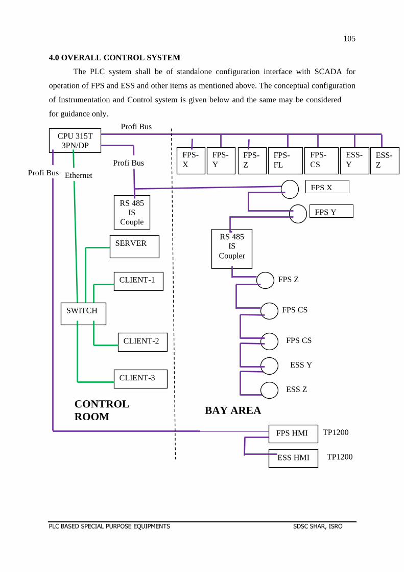
105
PLC BASED SPECIAL PURPOSE EQUIPMENTS SDSC SHAR, ISRO
4.0 OVERALL CONTROL SYSTEM
The PLC system shall be of standalone configuration interface with SCADA for
operation of FPS and ESS and other items as mentioned above. The conceptual configuration
of Instrumentation and Control system is given below and the same may be considered
for guidance only.
CPU 315T 3PN/DP
RS 485 IS
Couple
SWITCH
SERVER
CLIENT-1
CLIENT-2
CLIENT-3
FPS X
FPS Y
FPS Z
FPS CS
ESS Y
ESS Z
FPS CS
FPS-Z
FPS-X
FPS-Y
FPS-FL
FPS-CS
ESS-Y
ESS-Z
Profi Bus Profi Bus
Profi Bus
BAY AREA CONTROL ROOM
TP1200
TP1200
Ethernet
ESS HMI
FPS HMI
RS 485 IS
Coupler
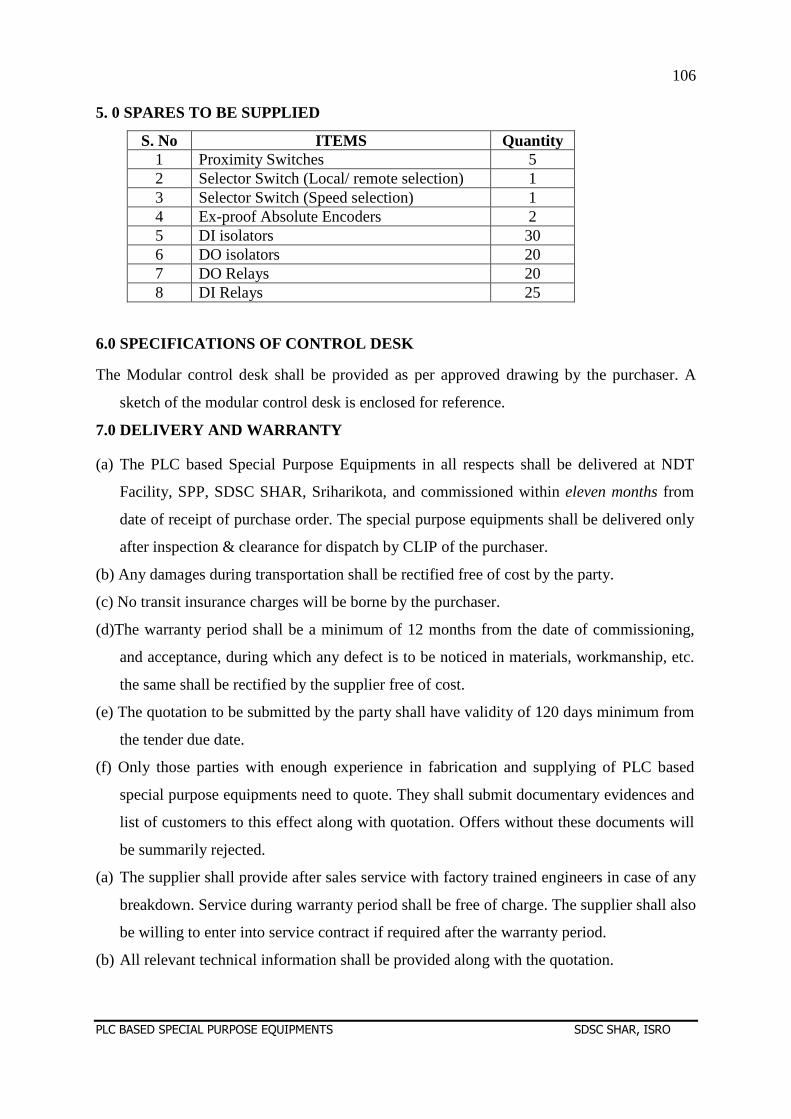
106
PLC BASED SPECIAL PURPOSE EQUIPMENTS SDSC SHAR, ISRO
5. 0 SPARES TO BE SUPPLIED
S. No ITEMS Quantity 1 Proximity Switches 5 2 Selector Switch (Local/ remote selection) 1 3 Selector Switch (Speed selection) 1 4 Ex-proof Absolute Encoders 2 5 DI isolators 30 6 DO isolators 20 7 DO Relays 20 8 DI Relays 25
6.0 SPECIFICATIONS OF CONTROL DESK
The Modular control desk shall be provided as per approved drawing by the purchaser. A
sketch of the modular control desk is enclosed for reference.
7.0 DELIVERY AND WARRANTY
(a) The PLC based Special Purpose Equipments in all respects shall be delivered at NDT
Facility, SPP, SDSC SHAR, Sriharikota, and commissioned within eleven months from
date of receipt of purchase order. The special purpose equipments shall be delivered only
after inspection & clearance for dispatch by CLIP of the purchaser.
(b) Any damages during transportation shall be rectified free of cost by the party.
(c) No transit insurance charges will be borne by the purchaser.
(d)The warranty period shall be a minimum of 12 months from the date of commissioning,
and acceptance, during which any defect is to be noticed in materials, workmanship, etc.
the same shall be rectified by the supplier free of cost.
(e) The quotation to be submitted by the party shall have validity of 120 days minimum from
the tender due date.
(f) Only those parties with enough experience in fabrication and supplying of PLC based
special purpose equipments need to quote. They shall submit documentary evidences and
list of customers to this effect along with quotation. Offers without these documents will
be summarily rejected.
(a) The supplier shall provide after sales service with factory trained engineers in case of any
breakdown. Service during warranty period shall be free of charge. The supplier shall also
be willing to enter into service contract if required after the warranty period.
(b) All relevant technical information shall be provided along with the quotation.
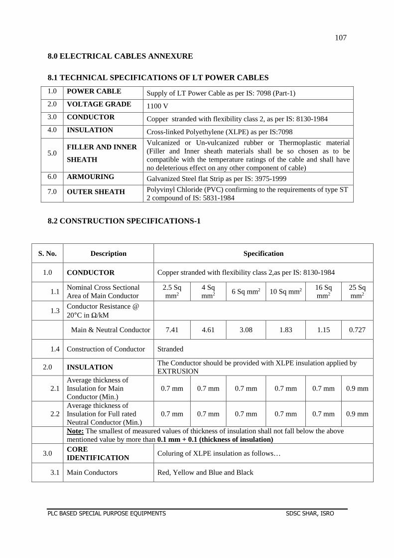
107
PLC BASED SPECIAL PURPOSE EQUIPMENTS SDSC SHAR, ISRO
8.0 ELECTRICAL CABLES ANNEXURE
8.1 TECHNICAL SPECIFICATIONS OF LT POWER CABLES
1.0 POWER CABLE Supply of LT Power Cable as per IS: 7098 (Part-1) 2.0 VOLTAGE GRADE 1100 V 3.0 CONDUCTOR Copper stranded with flexibility class 2, as per IS: 8130-1984 4.0 INSULATION Cross-linked Polyethylene (XLPE) as per IS:7098
5.0 FILLER AND INNER
SHEATH
Vulcanized or Un-vulcanized rubber or Thermoplastic material (Filler and Inner sheath materials shall be so chosen as to be compatible with the temperature ratings of the cable and shall have no deleterious effect on any other component of cable)
6.0 ARMOURING Galvanized Steel flat Strip as per IS: 3975-1999
7.0 OUTER SHEATH Polyvinyl Chloride (PVC) confirming to the requirements of type ST 2 compound of IS: 5831-1984
8.2 CONSTRUCTION SPECIFICATIONS-1
S. No. Description Specification
1.0 CONDUCTOR Copper stranded with flexibility class 2,as per IS: 8130-1984
1.1 Nominal Cross Sectional Area of Main Conductor
2.5 Sq mm2
4 Sq mm2 6 Sq mm2 10 Sq mm2 16 Sq
mm2 25 Sq mm2
1.3 Conductor Resistance @ 20°C in Ω/kM
Main & Neutral Conductor 7.41 4.61 3.08 1.83 1.15 0.727
1.4 Construction of Conductor Stranded
2.0 INSULATION The Conductor should be provided with XLPE insulation applied by EXTRUSION
2.1 Average thickness of Insulation for Main Conductor (Min.)
0.7 mm 0.7 mm 0.7 mm 0.7 mm 0.7 mm 0.9 mm
2.2 Average thickness of Insulation for Full rated Neutral Conductor (Min.)
0.7 mm 0.7 mm 0.7 mm 0.7 mm 0.7 mm 0.9 mm
Note: The smallest of measured values of thickness of insulation shall not fall below the above mentioned value by more than 0.1 mm + 0.1 (thickness of insulation)
3.0 CORE IDENTIFICATION Coluring of XLPE insulation as follows…
3.1 Main Conductors Red, Yellow and Blue and Black
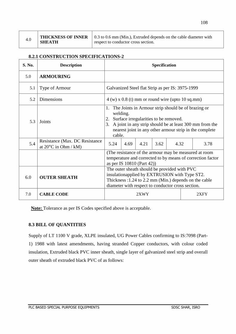
108
PLC BASED SPECIAL PURPOSE EQUIPMENTS SDSC SHAR, ISRO
4.0 THICKNESS OF INNER SHEATH
0.3 to 0.6 mm (Min.), Extruded depends on the cable diameter with respect to conductor cross section.
8.2.1 CONSTRUCTION SPECIFICATIONS-2
S. No. Description Specification
5.0 ARMOURING
5.1 Type of Armour Galvanized Steel flat Strip as per IS: 3975-1999
5.2 Dimensions 4 (w) x 0.8 (t) mm or round wire (upto 10 sq.mm)
5.3 Joints
1. The Joints in Armour strip should be of brazing or welding.
2. Surface irregularities to be removed. 3. A joint in any strip should be at least 300 mm from the
nearest joint in any other armour strip in the complete cable.
5.4 Resistance (Max. DC Resistance at 20°C in Ohm / kM)
5.24 4.69 4.21 3.62 4.32 3.78
(The resistance of the armour may be measured at room temperature and corrected to by means of correction factor as per IS 10810 (Part 42))
6.0 OUTER SHEATH
The outer sheath should be provided with PVC insulationapplied by EXTRUSION with Type ST2. Thickness :1.24 to 2.2 mm (Min.) depends on the cable diameter with respect to conductor cross section.
7.0 CABLE CODE 2XWY 2XFY
Note: Tolerance as per IS Codes specified above is acceptable.
8.3 BILL OF QUANTITIES Supply of LT 1100 V grade, XLPE insulated, UG Power Cables confirming to IS:7098 (Part-
1) 1988 with latest amendments, having stranded Copper conductors, with colour coded
insulation, Extruded black PVC inner sheath, single layer of galvanized steel strip and overall
outer sheath of extruded black PVC of as follows:
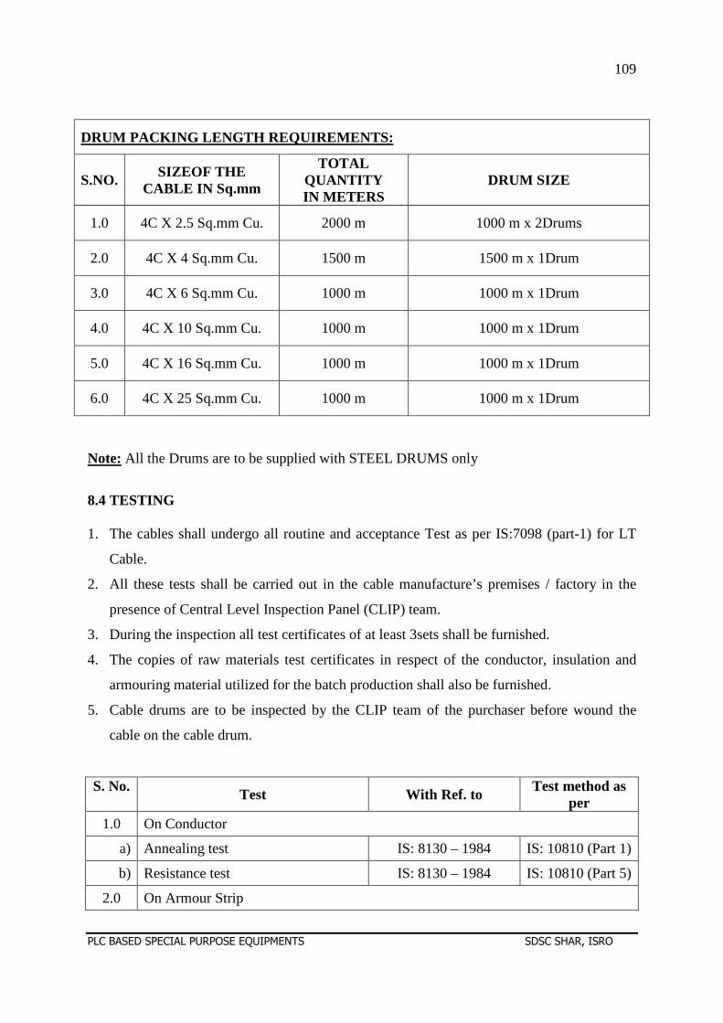
109
PLC BASED SPECIAL PURPOSE EQUIPMENTS SDSC SHAR, ISRO
DRUM PACKING LENGTH REQUIREMENTS:
S.NO. SIZEOF THE CABLE IN Sq.mm
TOTAL QUANTITY IN METERS
DRUM SIZE
1.0 4C X 2.5 Sq.mm Cu. 2000 m 1000 m x 2Drums
2.0 4C X 4 Sq.mm Cu. 1500 m 1500 m x 1Drum
3.0 4C X 6 Sq.mm Cu. 1000 m 1000 m x 1Drum
4.0 4C X 10 Sq.mm Cu. 1000 m 1000 m x 1Drum
5.0 4C X 16 Sq.mm Cu. 1000 m 1000 m x 1Drum
6.0 4C X 25 Sq.mm Cu. 1000 m 1000 m x 1Drum
Note: All the Drums are to be supplied with STEEL DRUMS only
8.4 TESTING 1. The cables shall undergo all routine and acceptance Test as per IS:7098 (part-1) for LT
Cable.
2. All these tests shall be carried out in the cable manufacture’s premises / factory in the
presence of Central Level Inspection Panel (CLIP) team.
3. During the inspection all test certificates of at least 3sets shall be furnished.
4. The copies of raw materials test certificates in respect of the conductor, insulation and
armouring material utilized for the batch production shall also be furnished.
5. Cable drums are to be inspected by the CLIP team of the purchaser before wound the
cable on the cable drum.
S. No. Test With Ref. to
Test method as per
1.0 On Conductor
a) Annealing test IS: 8130 – 1984 IS: 10810 (Part 1)
b) Resistance test IS: 8130 – 1984 IS: 10810 (Part 5)
2.0 On Armour Strip
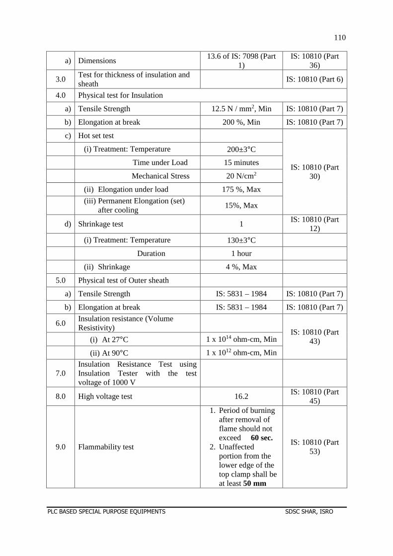
110
PLC BASED SPECIAL PURPOSE EQUIPMENTS SDSC SHAR, ISRO
a) Dimensions 13.6 of IS: 7098 (Part
1) IS: 10810 (Part
36)
3.0 Test for thickness of insulation and sheath
IS: 10810 (Part 6)
4.0 Physical test for Insulation
a) Tensile Strength 12.5 N / mm2, Min IS: 10810 (Part 7)
b) Elongation at break 200 %, Min IS: 10810 (Part 7)
c) Hot set test
IS: 10810 (Part 30)
(i) Treatment: Temperature 200±3°C
Time under Load 15 minutes
Mechanical Stress 20 N/cm2
(ii) Elongation under load 175 %, Max
(iii) Permanent Elongation (set)
after cooling 15%, Max
d) Shrinkage test 1 IS: 10810 (Part
12)
(i) Treatment: Temperature 130±3°C
Duration 1 hour
(ii) Shrinkage 4 %, Max
5.0 Physical test of Outer sheath
a) Tensile Strength IS: 5831 – 1984 IS: 10810 (Part 7)
b) Elongation at break IS: 5831 – 1984 IS: 10810 (Part 7)
6.0 Insulation resistance (Volume Resistivity)
IS: 10810 (Part
43) (i) At 27°C 1 x 10¹⁴ ohm-cm, Min
(ii) At 90°C 1 x 10¹² ohm-cm, Min
7.0 Insulation Resistance Test using Insulation Tester with the test voltage of 1000 V
8.0 High voltage test 16.2 IS: 10810 (Part
45)
9.0 Flammability test
1. Period of burning after removal of flame should not exceed 60 sec.
2. Unaffected portion from the lower edge of the top clamp shall be at least 50 mm
IS: 10810 (Part 53)
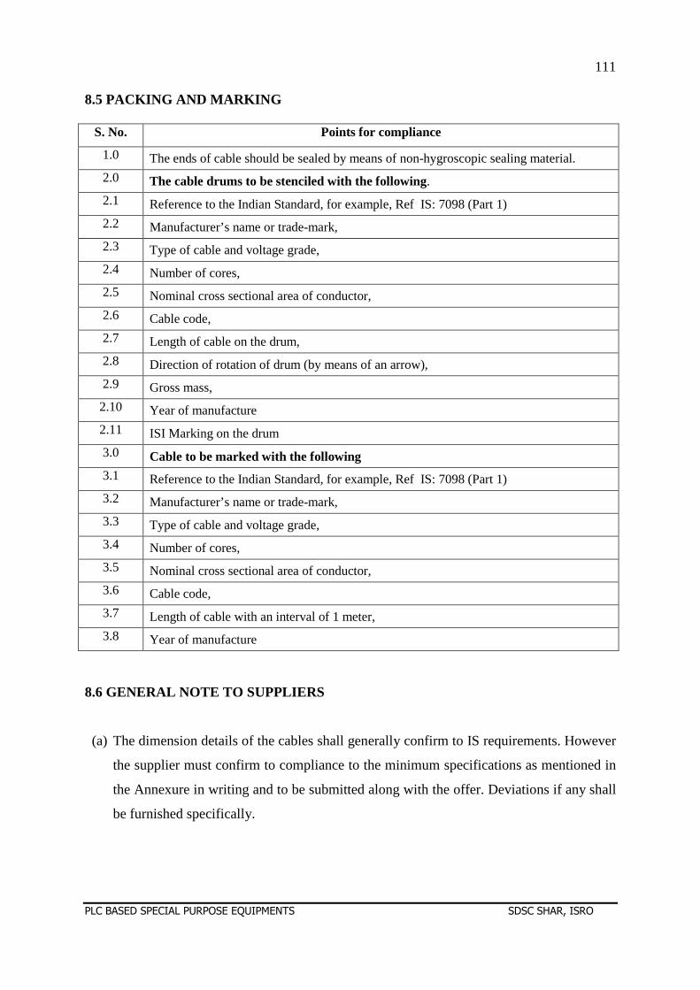
111
PLC BASED SPECIAL PURPOSE EQUIPMENTS SDSC SHAR, ISRO
8.5 PACKING AND MARKING
S. No. Points for compliance
1.0 The ends of cable should be sealed by means of non-hygroscopic sealing material. 2.0 The cable drums to be stenciled with the following. 2.1 Reference to the Indian Standard, for example, Ref IS: 7098 (Part 1) 2.2 Manufacturer’s name or trade-mark, 2.3 Type of cable and voltage grade, 2.4 Number of cores, 2.5 Nominal cross sectional area of conductor, 2.6 Cable code, 2.7 Length of cable on the drum, 2.8 Direction of rotation of drum (by means of an arrow), 2.9 Gross mass, 2.10 Year of manufacture 2.11 ISI Marking on the drum 3.0 Cable to be marked with the following 3.1 Reference to the Indian Standard, for example, Ref IS: 7098 (Part 1) 3.2 Manufacturer’s name or trade-mark, 3.3 Type of cable and voltage grade, 3.4 Number of cores, 3.5 Nominal cross sectional area of conductor, 3.6 Cable code, 3.7 Length of cable with an interval of 1 meter, 3.8 Year of manufacture
8.6 GENERAL NOTE TO SUPPLIERS (a) The dimension details of the cables shall generally confirm to IS requirements. However
the supplier must confirm to compliance to the minimum specifications as mentioned in
the Annexure in writing and to be submitted along with the offer. Deviations if any shall
be furnished specifically.
112
PLC BASED SPECIAL PURPOSE EQUIPMENTS SDSC SHAR, ISRO
(b) The cable shall be guaranteed against manufacturing defects for a period of not less than
18 months from the date of supply or 12 months from the date of installation which ever
is earlier.
(c) The cables required to be supplied in lengths as mentioned in the Annexure-4-B. The
supply quantity tolerance limit up to + 5% (+ tolerance only acceptable) is acceptable.
(d) The tenderes shall furnish a data sheet / product catalogue containing all the technical
parameters /information or confirm clearly whether the cables quoted will meet all the
parameters / particulars asked for.
(e) The following test certificates to be handed over in hard copies – 3 sets: Type test,
Routine Test, Acceptance test along with material certificates.
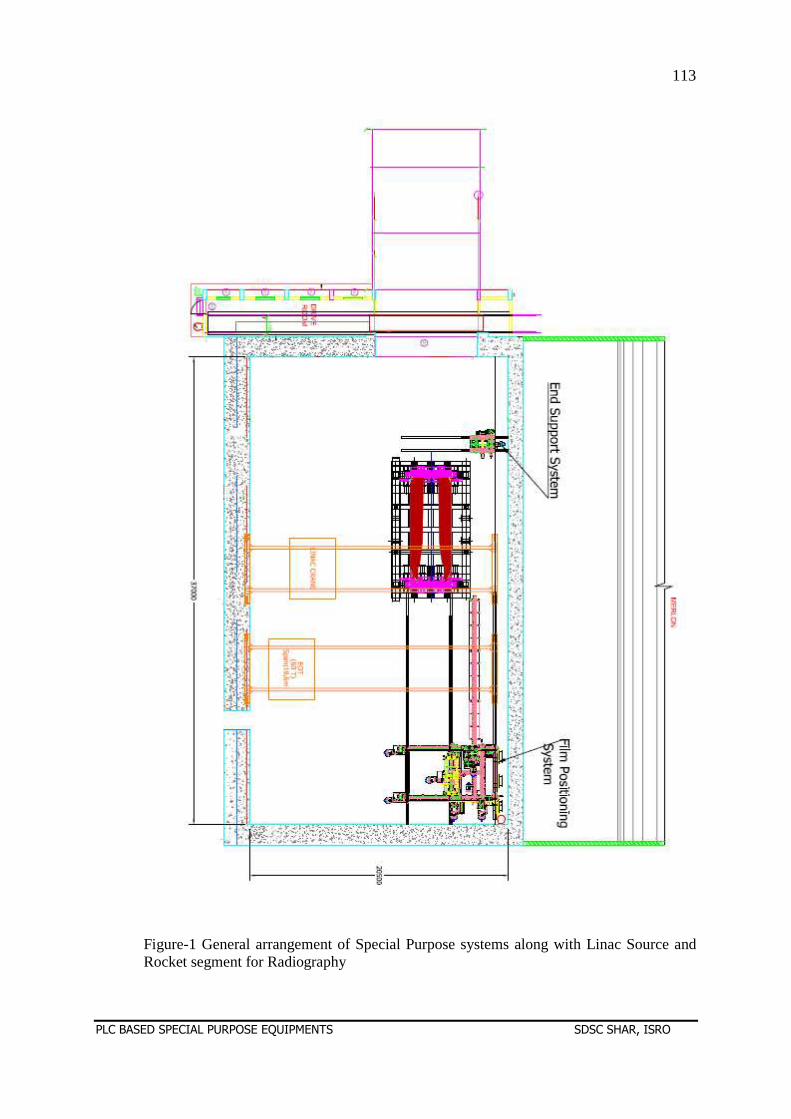
113
PLC BASED SPECIAL PURPOSE EQUIPMENTS SDSC SHAR, ISRO
Figure-1 General arrangement of Special Purpose systems along with Linac Source and Rocket segment for Radiography
114
PLC BASED SPECIAL PURPOSE EQUIPMENTS SDSC SHAR, ISRO
SECTION –D
ANNEXURES
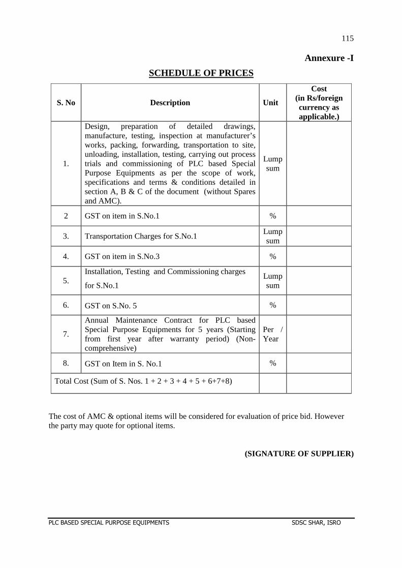
115
PLC BASED SPECIAL PURPOSE EQUIPMENTS SDSC SHAR, ISRO
Annexure -I
SCHEDULE OF PRICES
S. No Description Unit
Cost (in Rs/foreign currency as applicable.)
1.
Design, preparation of detailed drawings, manufacture, testing, inspection at manufacturer’s works, packing, forwarding, transportation to site, unloading, installation, testing, carrying out process trials and commissioning of PLC based Special Purpose Equipments as per the scope of work, specifications and terms & conditions detailed in section A, B & C of the document (without Spares and AMC).
Lump sum
2 GST on item in S.No.1 %
3. Transportation Charges for S.No.1 Lump sum
4. GST on item in S.No.3 %
5. Installation, Testing and Commissioning charges
for S.No.1 Lump sum
6. GST on S.No. 5 %
7.
Annual Maintenance Contract for PLC based Special Purpose Equipments for 5 years (Starting from first year after warranty period) (Non-comprehensive)
Per / Year
8. GST on Item in S. No.1 %
Total Cost (Sum of S. Nos. 1 + 2 + 3 + 4 + 5 + 6+7+8)
The cost of AMC & optional items will be considered for evaluation of price bid. However the party may quote for optional items.
(SIGNATURE OF SUPPLIER)
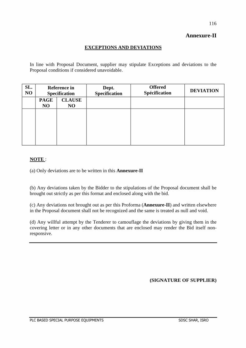
116
PLC BASED SPECIAL PURPOSE EQUIPMENTS SDSC SHAR, ISRO
Annexure-II
EXCEPTIONS AND DEVIATIONS In line with Proposal Document, supplier may stipulate Exceptions and deviations to the Proposal conditions if considered unavoidable.
SL.NO
Reference in Specification
Dept. Specification
Offered Spécification DEVIATION
PAGE NO
CLAUSE NO
NOTE : (a) Only deviations are to be written in this Annexure-II (b) Any deviations taken by the Bidder to the stipulations of the Proposal document shall be brought out strictly as per this format and enclosed along with the bid. (c) Any deviations not brought out as per this Proforma (Annexure-II ) and written elsewhere in the Proposal document shall not be recognized and the same is treated as null and void. (d) Any willful attempt by the Tenderer to camouflage the deviations by giving them in the covering letter or in any other documents that are enclosed may render the Bid itself non-responsive.
(SIGNATURE OF SUPPLIER)
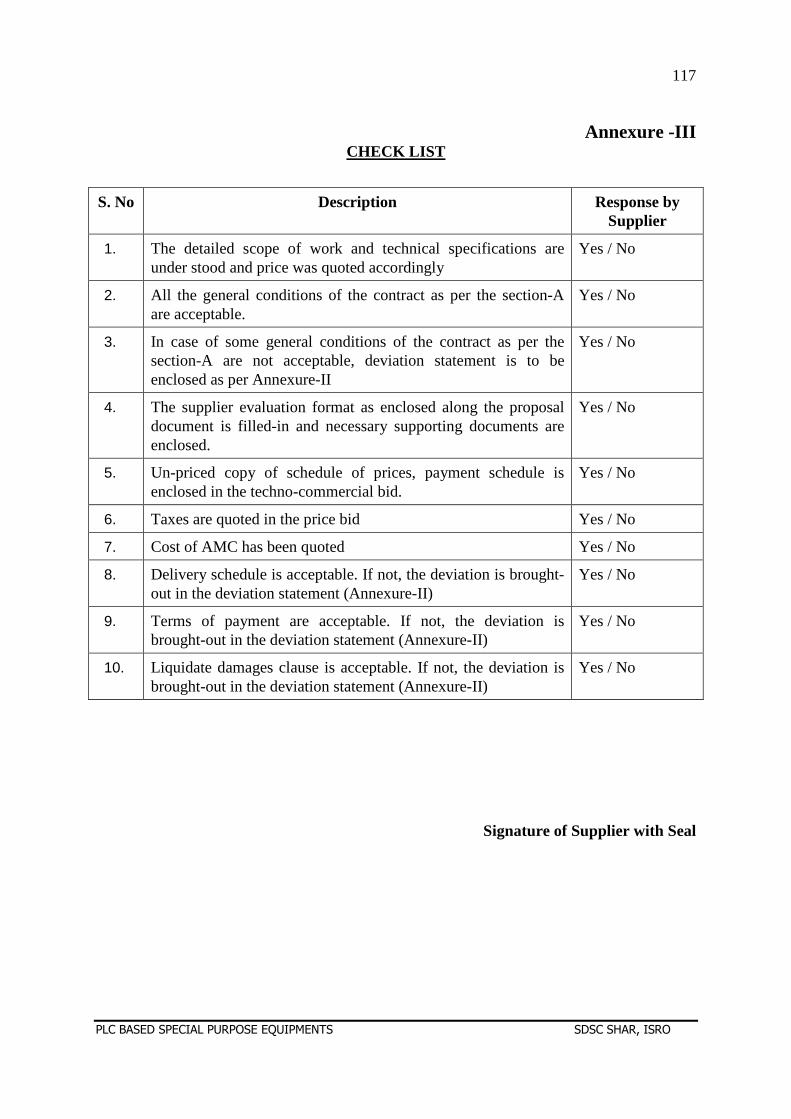
117
PLC BASED SPECIAL PURPOSE EQUIPMENTS SDSC SHAR, ISRO
Annexure -III
CHECK LIST
S. No Description Response by Supplier
1. The detailed scope of work and technical specifications are under stood and price was quoted accordingly
Yes / No
2. All the general conditions of the contract as per the section-A are acceptable.
Yes / No
3. In case of some general conditions of the contract as per the section-A are not acceptable, deviation statement is to be enclosed as per Annexure-II
Yes / No
4. The supplier evaluation format as enclosed along the proposal document is filled-in and necessary supporting documents are enclosed.
Yes / No
5. Un-priced copy of schedule of prices, payment schedule is enclosed in the techno-commercial bid.
Yes / No
6. Taxes are quoted in the price bid Yes / No
7. Cost of AMC has been quoted Yes / No
8. Delivery schedule is acceptable. If not, the deviation is brought-out in the deviation statement (Annexure-II)
Yes / No
9. Terms of payment are acceptable. If not, the deviation is brought-out in the deviation statement (Annexure-II)
Yes / No
10. Liquidate damages clause is acceptable. If not, the deviation is brought-out in the deviation statement (Annexure-II)
Yes / No
Signature of Supplier with Seal