PLC 21 FILTER PRESS (GBT) SYSTEM SCADA … Filter Press (GBT... · 5.3 Gravity Belt Thickener ......
31
PLC 21 – FILTER PRESS (GBT) SYSTEM SCADA SYSTEM OPERATION MANUAL Revision 1.0 July 7, 2006
-
Upload
truongthien -
Category
Documents
-
view
217 -
download
0
Transcript of PLC 21 FILTER PRESS (GBT) SYSTEM SCADA … Filter Press (GBT... · 5.3 Gravity Belt Thickener ......
PLC 21 – FILTER PRESS (GBT) SYSTEM
SCADA SYSTEM OPERATION MANUAL
Revision 1.0
July 7, 2006
Meyer Control Corporation Stockton RWCF WW32 / WW39 CH2M Hill / OMI – Thames Water
PLC 21 – FILTER PRESS (GBT) SYSTEM SCADA SYSTEM OPERATION MANUAL
Revision 1.0 July 7, 2006
Table of Contents
1 Introduction ........................................................................................................................................................................................................... 4 2 Revision History.................................................................................................................................................................................................... 4 3 Conventions........................................................................................................................................................................................................... 4
3.1 Set Points and Process Values ...................................................................................................................................................................... 4 3.2 Equipment Colors ......................................................................................................................................................................................... 5 3.3 Line sizes and colors .................................................................................................................................................................................... 5 3.4 Instrument Bubbles....................................................................................................................................................................................... 6
4 New Control Strategies ......................................................................................................................................................................................... 6 4.1 Primary Sludge Flow Control....................................................................................................................................................................... 6
4.1.1 Flow Measurement .............................................................................................................................................................................. 6 4.1.2 Flow Control Loop............................................................................................................................................................................... 6 4.1.3 Control Valves ..................................................................................................................................................................................... 6 4.1.4 Interlocks ............................................................................................................................................................................................. 7
4.2 Sludge Conditioning Polymer ...................................................................................................................................................................... 7 4.2.1 System Control .................................................................................................................................................................................... 7 4.2.2 Inventory Measurement ....................................................................................................................................................................... 8 4.2.3 Polymer Blend Units............................................................................................................................................................................ 8 4.2.4 Interlocks ............................................................................................................................................................................................. 9
4.3 Gravity Belt Thickeners................................................................................................................................................................................ 9 4.4 Thickening Recycle Pump Station ............................................................................................................................................................... 9
4.4.1 Level Control ..................................................................................................................................................................................... 10 4.4.2 Pump Control..................................................................................................................................................................................... 10 4.4.3 Interlocks ........................................................................................................................................................................................... 10
4.5 Thickened Sludge Pump Station................................................................................................................................................................. 11
July 7, 2006 – Rev. 1.0 PLC 21 Filter Press (GBT) System – SCADA System Operation Manual 2 of 31

Meyer Control Corporation Stockton RWCF WW32 / WW39 CH2M Hill / OMI – Thames Water
4.5.1 Level Control ..................................................................................................................................................................................... 11 4.5.2 Pump Control..................................................................................................................................................................................... 11 4.5.3 Interlocks ........................................................................................................................................................................................... 11 4.5.4 Flow Measurement ............................................................................................................................................................................ 12
5 Sample Screens .................................................................................................................................................................................................... 12 5.1 GBT System Overview............................................................................................................................................................................... 13 5.2 GBT Navigation Menu ............................................................................................................................................................................... 14 5.3 Gravity Belt Thickener ............................................................................................................................................................................... 15 5.4 Primary Sludge Feed .................................................................................................................................................................................. 16 5.5 Modulating Valve ....................................................................................................................................................................................... 17 5.6 Flow Control Loop ..................................................................................................................................................................................... 18 5.7 Sludge Conditioning Polymer .................................................................................................................................................................... 19 5.8 Polymer Blend Unit Pop Up....................................................................................................................................................................... 20 5.9 Sludge Polymer Set Points ......................................................................................................................................................................... 21 5.10 Thickening Recycle Pump Station ............................................................................................................................................................. 22 5.11 Recycle Level Control Loop....................................................................................................................................................................... 23 5.12 Recycle Pump Pop Up................................................................................................................................................................................ 24 5.13 Recycle Set Points ...................................................................................................................................................................................... 25 5.14 Thickened Sludge Pump Station................................................................................................................................................................. 26 5.15 Sludge Level Control Loop ........................................................................................................................................................................ 27 5.16 Thickened Sludge Pump Pop Up................................................................................................................................................................ 28 5.17 Thickened Sludge Set Points ...................................................................................................................................................................... 29 5.18 Flow Transmitter Pop Up ........................................................................................................................................................................... 30 5.19 Weight Transmitter Pop Up........................................................................................................................................................................ 31
July 7, 2006 – Rev. 1.0 PLC 21 Filter Press (GBT) System – SCADA System Operation Manual 3 of 31
Meyer Control Corporation Stockton RWCF WW32 / WW39 CH2M Hill / OMI – Thames Water
PLC 21 – FILTER PRESS (GBT) SYSTEM SCADA SYSTEM OPERATION MANUAL
Revision 1.0
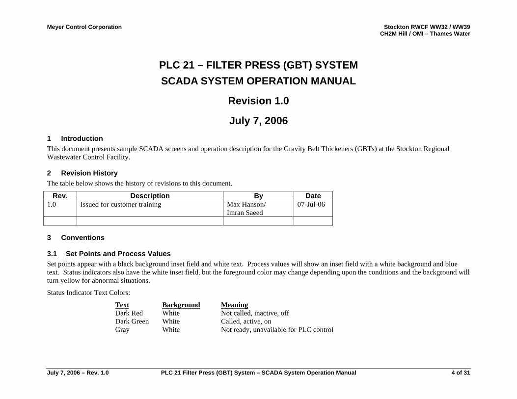
July 7, 2006 1 Introduction This document presents sample SCADA screens and operation description for the Gravity Belt Thickeners (GBTs) at the Stockton Regional Wastewater Control Facility.
2 Revision History The table below shows the history of revisions to this document.
Rev. Description By Date1.0 Issued for customer training Max Hanson/
Imran Saeed 07-Jul-06
3 Conventions
3.1 Set Points and Process Values Set points appear with a black background inset field and white text. Process values will show an inset field with a white background and blue text. Status indicators also have the white inset field, but the foreground color may change depending upon the conditions and the background will turn yellow for abnormal situations.
Status Indicator Text Colors:
Text Background MeaningDark Red White Not called, inactive, off Dark Green White Called, active, on Gray White Not ready, unavailable for PLC control
July 7, 2006 – Rev. 1.0 PLC 21 Filter Press (GBT) System – SCADA System Operation Manual 4 of 31
Meyer Control Corporation Stockton RWCF WW32 / WW39 CH2M Hill / OMI – Thames Water
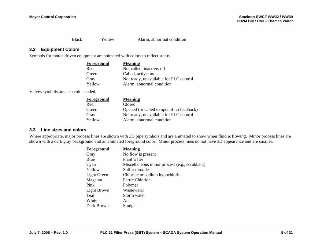
Black Yellow Alarm, abnormal condition
3.2 Equipment Colors Symbols for motor-driven equipment are animated with colors to reflect status.
Foreground MeaningRed Not called, inactive, off Green Called, active, on Gray Not ready, unavailable for PLC control Yellow Alarm, abnormal condition
Valves symbols are also color-coded.
Foreground MeaningRed Closed Green Opened (or called to open if no feedback) Gray Not ready, unavailable for PLC control Yellow Alarm, abnormal condition
3.3 Line sizes and colors Where appropriate, major process lines are shown with 3D pipe symbols and are animated to show when fluid is flowing. Minor process lines are shown with a dark gray background and an animated foreground color. Minor process lines do not have 3D appearance and are smaller.
Foreground MeaningGray No flow is present
Blue
Plant waterCyan Miscellaneous minor process (e.g., scrubbant)
Yellow Sulfur dioxideLight Green Chlorine or sodium hypochlorite
Magenta Ferric Chloride Pink Polymer
Light Brown
Wastewater Teal Storm water
White AirDark Brown Sludge
July 7, 2006 – Rev. 1.0 PLC 21 Filter Press (GBT) System – SCADA System Operation Manual 5 of 31
Meyer Control Corporation Stockton RWCF WW32 / WW39 CH2M Hill / OMI – Thames Water
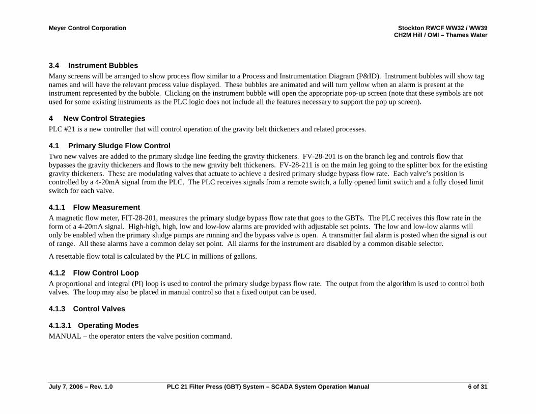
3.4 Instrument Bubbles Many screens will be arranged to show process flow similar to a Process and Instrumentation Diagram (P&ID). Instrument bubbles will show tag names and will have the relevant process value displayed. These bubbles are animated and will turn yellow when an alarm is present at the instrument represented by the bubble. Clicking on the instrument bubble will open the appropriate pop-up screen (note that these symbols are not used for some existing instruments as the PLC logic does not include all the features necessary to support the pop up screen).
4 New Control Strategies PLC #21 is a new controller that will control operation of the gravity belt thickeners and related processes.
4.1 Primary Sludge Flow Control Two new valves are added to the primary sludge line feeding the gravity thickeners. FV-28-201 is on the branch leg and controls flow that bypasses the gravity thickeners and flows to the new gravity belt thickeners. FV-28-211 is on the main leg going to the splitter box for the existing gravity thickeners. These are modulating valves that actuate to achieve a desired primary sludge bypass flow rate. Each valve’s position is controlled by a 4-20mA signal from the PLC. The PLC receives signals from a remote switch, a fully opened limit switch and a fully closed limit switch for each valve.
4.1.1 Flow Measurement A magnetic flow meter, FIT-28-201, measures the primary sludge bypass flow rate that goes to the GBTs. The PLC receives this flow rate in the form of a 4-20mA signal. High-high, high, low and low-low alarms are provided with adjustable set points. The low and low-low alarms will only be enabled when the primary sludge pumps are running and the bypass valve is open. A transmitter fail alarm is posted when the signal is out of range. All these alarms have a common delay set point. All alarms for the instrument are disabled by a common disable selector.
A resettable flow total is calculated by the PLC in millions of gallons.
4.1.2 Flow Control Loop A proportional and integral (PI) loop is used to control the primary sludge bypass flow rate. The output from the algorithm is used to control both valves. The loop may also be placed in manual control so that a fixed output can be used.
4.1.3 Control Valves
4.1.3.1 Operating Modes MANUAL – the operator enters the valve position command.
July 7, 2006 – Rev. 1.0 PLC 21 Filter Press (GBT) System – SCADA System Operation Manual 6 of 31
Meyer Control Corporation Stockton RWCF WW32 / WW39 CH2M Hill / OMI – Thames Water
AUTOMATIC – The valves modulate when either GBT is running and the primary sludge feed selector switch is set to ON. When the GBTs are off, FV-28-201 will close and FV-28-211 will go to 100% open.
4.1.3.2 Monitoring SCADA and OIT displays show local / remote, ready, limit switch and position command status information. A valve fail to open alarm is posted if the closed limit switch signal is received when the position command is above 5% for a delay period. Similarly a fail to close alarm will be posted when the open limit switch remains energized and the position command is below 95%. The valve is considered READY if it is in remote mode and has no failure alarms active. Alarms for each valve may be disabled.
4.1.4 Interlocks The primary sludge pumps (controlled by PLC #4) will be prevented from operation if both FV-28-201 and FV-28-211 are fully closed.
4.2 Sludge Conditioning Polymer
4.2.1 System Control The polymer system feeds polymer to the sludge immediately upstream of the gravity belt thickeners. A manual isolation valve allows for two modes of operation. If the valve is closed, the operator should select the ISOLATED mode. If the valve is open, the operator should select COMMON mode on the SCADA or OIT.
4.2.1.1 Isolated Mode In this normal operating mode, each polymer blend unit (PBU) is dedicated to a single GBT. It will start and stop in response to the operation of the GBT with the same number and it will receive its dose command from that GBT.
4.2.1.2 Common Mode If the isolation valve is open, the operator should select the COMMON mode, wherein the discharge of the PBUs is tied together, allowing one PBU to serve both GBTs. When common mode is selected, any PBU that is in automatic mode and ready for PLC control will start when either GBT is ready for sludge. If both GBTs are running the dose requests are averaged to determine the required polymer flow rate. If only one GBT is running, its dose command is used. If two PBUs are running, each will be commanded to provide half the polymer flow. It should be noted that, if operating a single GBT in COMMON mode, the operator should close an isolation valve in the polymer feed line to the GBT that is offline to prevent polymer addition where it is not desired.
4.2.1.3 Dose Calculation The target raw polymer flow rate is calculated by the equation below.
July 7, 2006 – Rev. 1.0 PLC 21 Filter Press (GBT) System – SCADA System Operation Manual 7 of 31
Meyer Control Corporation Stockton RWCF WW32 / WW39 CH2M Hill / OMI – Thames Water
Polymer Flow (gph) = 6 x Sludge Flow x Sludge Concentration x Dose
Activity x Specific Gravity x 2 x 10⁸
Sludge Flow is the sum of the primary sludge bypass flow rate (FIT-28-201) and the secondary sludge flow rates (FI-23-201~FI-23-204) in gallons per minute.
Sludge concentration is the estimated weight of dry sludge in milligrams per milliliter of sludge.
Dose is the amount of raw polymer per ton of dry sludge requested by the GBT in pounds per ton.
Activity is a polymer activity constant entered by the operator in percent.
4.2.2 Inventory Measurement Two polymer totes are used to store the raw polymer. These totes are located on scales that transmit 4-20mA signals to the PLC. The outlets of the two totes are tied together to feed the polymer blend units. High-high, high, low and low-low weight alarms are furnished for each tote, as is a weight transmitter failure alarm.
4.2.3 Polymer Blend Units
4.2.3.1 Operating Modes MANUAL – In manual mode, the operator turns the PBU on or off and sets the desired raw polymer flow rate and concentration of diluted polymer solution.
AUTOMATIC – In automatic mode, the PLC will start and stop the PBU in response to GBT operation and system mode. Desired raw polymer flow rate is calculated as described above. The operator sets the desired concentration for the dilute polymer solution independently for each PBU.
4.2.3.2 Monitoring The PBU sends the PLC the following status signals: FAULT – shows as a failure alarm on SCADA and OIT screens LOW FLOW – low dilution water flow rate REMOTE – set to remote control PUMP – running or off SPEED – pump speed (4-20mA) FLOW RATE – dilution water flow rate (4-20mA)
The PLC sends the PBU the following commands:
July 7, 2006 – Rev. 1.0 PLC 21 Filter Press (GBT) System – SCADA System Operation Manual 8 of 31
Meyer Control Corporation Stockton RWCF WW32 / WW39 CH2M Hill / OMI – Thames Water
CALL – run command FLOW COMMAND – desired raw polymer flow rate (4-20mA) CONCENTRATION – desired dilute polymer solution concentration (4-20mA)
The PLC tracks run time for the PBU and posts a failure alarm when the fault signal is present or the PBU does not respond with a running signal after being called for a time delay.
4.2.4 Interlocks A low-low level in both polymer totes prevents automatic operation of the PBUs.
A PBU failure alarm is triggered if a PBU faults or fails to run when called to do so. This alarm latches until reset by an operator. A PBU will not be called if it has failed.
4.3 Gravity Belt Thickeners The GBTs are skid-mounted machines that incorporate their own PLC controls. The plant control system interacts with the GBTs in a supervisory manner, issuing start and stop commands and receiving status information.
Status signals monitored by PLC #21 and displayed on SCADA and OIT screens include: GENERAL FAULT – Fault signal from GBT (shows as failure on SCADA) BELT DRIVE – Belt drive running or off THICKENER ON – GBT system is active WASH PUMP – Wash pump running or off HYDRAULIC POWER UNIT – Hydraulic pump running or off READY – GBT is ready for sludge (note that this ready signal differs from “ready for PLC control” signals for other plant equipment) REMOTE – GBT in remote auto mode versus local manual POLYMER DOSE – Requested polymer dose (4-20mA)
PLC #21 generates a failure alarm if the general fault signal is present or the GBT does not respond with a Thickener On signal within a time delay after being called. The PLC also tracks runtime.
4.4 Thickening Recycle Pump Station The thickening recycle pump station receives filtrate and wash water from the GBTs. It pumps this fluid to the influent distribution structure of the primaries.
July 7, 2006 – Rev. 1.0 PLC 21 Filter Press (GBT) System – SCADA System Operation Manual 9 of 31
Meyer Control Corporation Stockton RWCF WW32 / WW39 CH2M Hill / OMI – Thames Water
4.4.1 Level Control An ultrasonic level transmitter measures the level of fluid in the wet well. A PI control loop is used to vary the speed of the operating pump in order to maintain the level at a target set point. High-high, high, low and low-low level alarms with adjustable set points are provided for this instrument. An out of range signal triggers a failure alarm. In addition to the transmitter, high and low level switches also monitor the level. These provide for redundant high and low alarms.
4.4.2 Pump Control Only one pump runs at a time. The pumps are controlled in an Active / Standby pair. The operator may specify the active pump or the assignment may be set to rotate based upon operating time.
4.4.2.1 Operating Modes MANUAL – The pump starts and stops in response to pushbuttons. Speed may be set from the operator interface.
AUTOMATIC – The pump starts and stops in response to system operating conditions. Speed is controlled by the level control loop.
4.4.2.2 Monitoring The following status points are monitored and displayed on the operator interface. REMOTE – VFD is set for remote (PLC) control rather than local keypad control. READY – Pump is ready for PLC control (in remote and not failed) FAULT – VFD is reporting a fault condition. FAIL – Either a fault has been present for a delay time or the VFD did not return a running status after being called for a delay period. RUNNING – Motor is running. CALLED – VFD is called to run by the PLC. SPEED COMMAND – The speed requested by the PLC (%). SPEED – Actual speed at which the VFD is operating (%). CURRENT – Current output of the VFD to the motor (Amps). RUNTIME – Reported in tenths of an hour.
4.4.3 Interlocks A low-low level alarm or a low level switch alarm will prevent automatic operation of the thickened sludge pumps.
A pump failure alarm is triggered if a VFD faults or fails to run when called to do so. This alarm latches until reset by an operator. A pump will not be called if it has failed.
July 7, 2006 – Rev. 1.0 PLC 21 Filter Press (GBT) System – SCADA System Operation Manual 10 of 31
Meyer Control Corporation Stockton RWCF WW32 / WW39 CH2M Hill / OMI – Thames Water
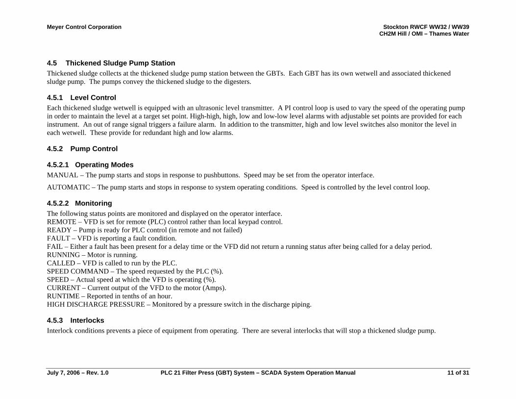
4.5 Thickened Sludge Pump Station Thickened sludge collects at the thickened sludge pump station between the GBTs. Each GBT has its own wetwell and associated thickened sludge pump. The pumps convey the thickened sludge to the digesters.
4.5.1 Level Control Each thickened sludge wetwell is equipped with an ultrasonic level transmitter. A PI control loop is used to vary the speed of the operating pump in order to maintain the level at a target set point. High-high, high, low and low-low level alarms with adjustable set points are provided for each instrument. An out of range signal triggers a failure alarm. In addition to the transmitter, high and low level switches also monitor the level in each wetwell. These provide for redundant high and low alarms.
4.5.2 Pump Control
4.5.2.1 Operating Modes MANUAL – The pump starts and stops in response to pushbuttons. Speed may be set from the operator interface.
AUTOMATIC – The pump starts and stops in response to system operating conditions. Speed is controlled by the level control loop.
4.5.2.2 Monitoring The following status points are monitored and displayed on the operator interface. REMOTE – VFD is set for remote (PLC) control rather than local keypad control. READY – Pump is ready for PLC control (in remote and not failed) FAULT – VFD is reporting a fault condition. FAIL – Either a fault has been present for a delay time or the VFD did not return a running status after being called for a delay period. RUNNING – Motor is running. CALLED – VFD is called to run by the PLC. SPEED COMMAND – The speed requested by the PLC (%). SPEED – Actual speed at which the VFD is operating (%). CURRENT – Current output of the VFD to the motor (Amps). RUNTIME – Reported in tenths of an hour. HIGH DISCHARGE PRESSURE – Monitored by a pressure switch in the discharge piping.
4.5.3 Interlocks Interlock conditions prevents a piece of equipment from operating. There are several interlocks that will stop a thickened sludge pump.
July 7, 2006 – Rev. 1.0 PLC 21 Filter Press (GBT) System – SCADA System Operation Manual 11 of 31
Meyer Control Corporation Stockton RWCF WW32 / WW39 CH2M Hill / OMI – Thames Water
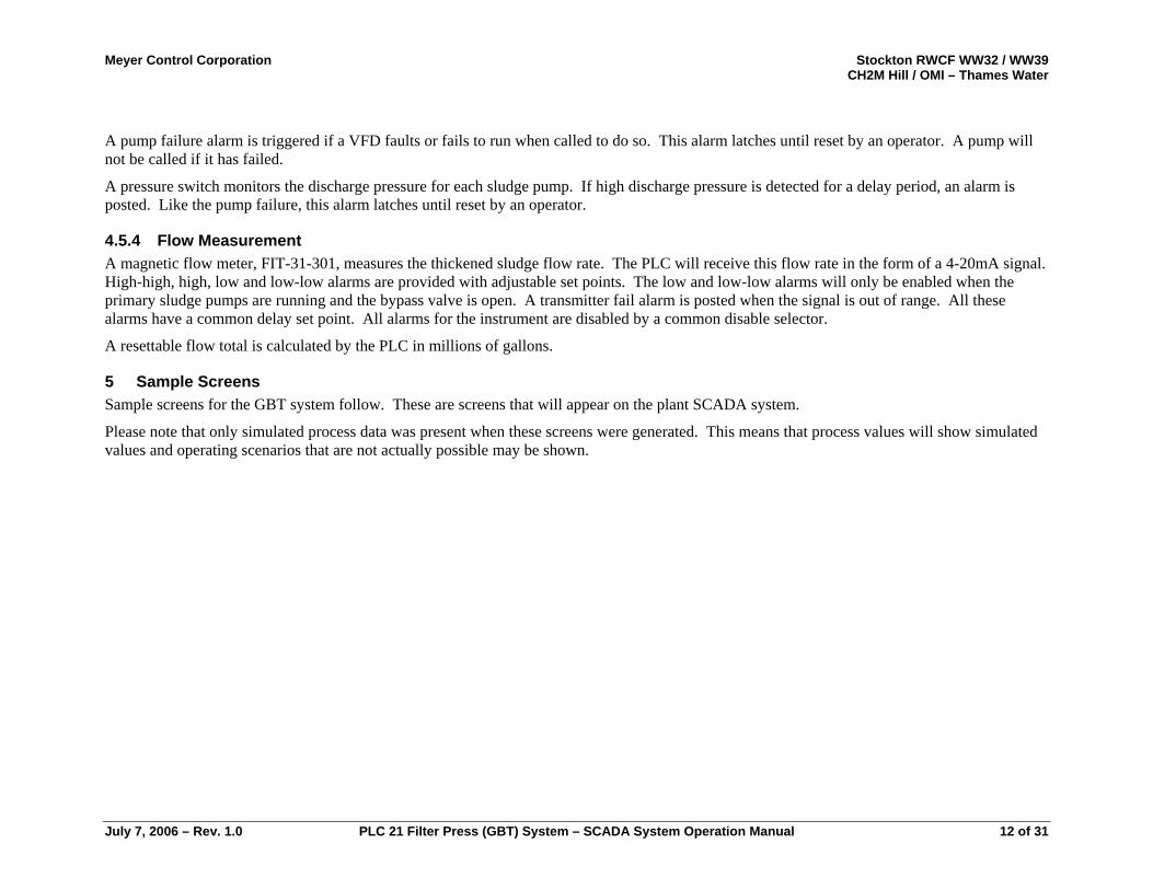
A pump failure alarm is triggered if a VFD faults or fails to run when called to do so. This alarm latches until reset by an operator. A pump will not be called if it has failed.
A pressure switch monitors the discharge pressure for each sludge pump. If high discharge pressure is detected for a delay period, an alarm is posted. Like the pump failure, this alarm latches until reset by an operator.
4.5.4 Flow Measurement A magnetic flow meter, FIT-31-301, measures the thickened sludge flow rate. The PLC will receive this flow rate in the form of a 4-20mA signal. High-high, high, low and low-low alarms are provided with adjustable set points. The low and low-low alarms will only be enabled when the primary sludge pumps are running and the bypass valve is open. A transmitter fail alarm is posted when the signal is out of range. All these alarms have a common delay set point. All alarms for the instrument are disabled by a common disable selector.
A resettable flow total is calculated by the PLC in millions of gallons.
5 Sample Screens Sample screens for the GBT system follow. These are screens that will appear on the plant SCADA system.
Please note that only simulated process data was present when these screens were generated. This means that process values will show simulated values and operating scenarios that are not actually possible may be shown.
July 7, 2006 – Rev. 1.0 PLC 21 Filter Press (GBT) System – SCADA System Operation Manual 12 of 31
Meyer Control Corporation Stockton RWCF WW32 / WW39 CH2M Hill / OMI – Thames Water
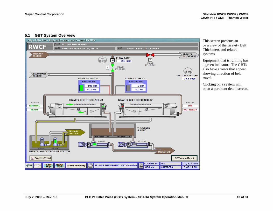
5.1 GBT System Overview This screen presents an overview of the Gravity Belt Thickeners and related systems.
Equipment that is running has a green indicator. The GBTs also have arrows that appear showing direction of belt travel.
Clicking on a system will open a pertinent detail screen.
July 7, 2006 – Rev. 1.0 PLC 21 Filter Press (GBT) System – SCADA System Operation Manual 13 of 31
Meyer Control Corporation Stockton RWCF WW32 / WW39 CH2M Hill / OMI – Thames Water
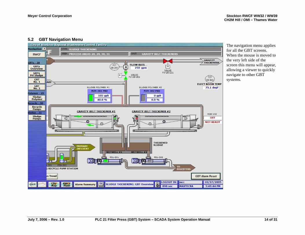
5.2 GBT Navigation Menu The navigation menu applies for all the GBT screens. When the mouse is moved to the very left side of the screen this menu will appear, allowing a viewer to quickly navigate to other GBT systems.
July 7, 2006 – Rev. 1.0 PLC 21 Filter Press (GBT) System – SCADA System Operation Manual 14 of 31
Meyer Control Corporation Stockton RWCF WW32 / WW39 CH2M Hill / OMI – Thames Water
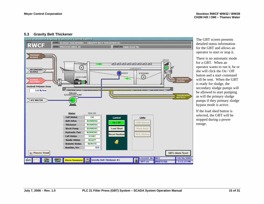
5.3 Gravity Belt Thickener The GBT screen presents detailed status information for the GBT and allows an operator to start or stop it.
There is no automatic mode for a GBT. When an operator wants to run it, he or she will click the On / Off button and a start command will be sent. When the GBT is ready for sludge, the secondary sludge pumps will be allowed to start pumping as will the primary sludge pumps if they primary sludge bypass mode is active.
If the load shed button is selected, the GBT will be stopped during a power outage.
July 7, 2006 – Rev. 1.0 PLC 21 Filter Press (GBT) System – SCADA System Operation Manual 15 of 31
Meyer Control Corporation Stockton RWCF WW32 / WW39 CH2M Hill / OMI – Thames Water
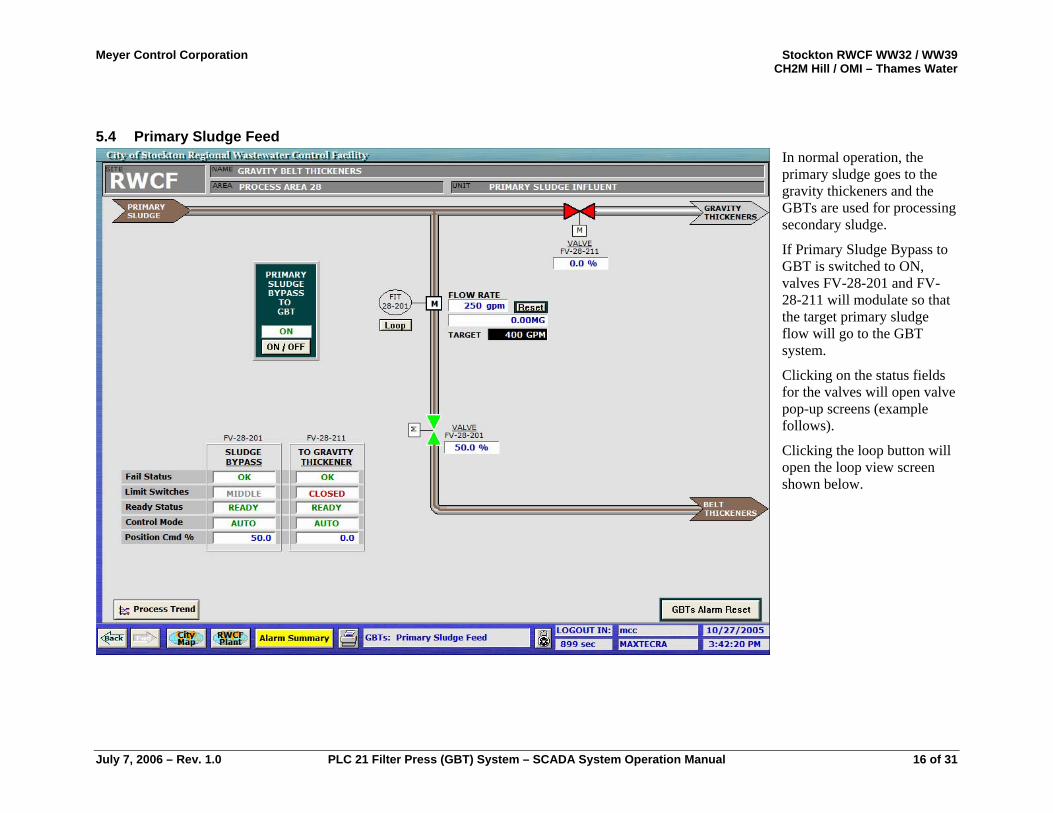
5.4 Primary Sludge Feed In normal operation, the primary sludge goes to the gravity thickeners and the GBTs are used for processing secondary sludge.
If Primary Sludge Bypass to GBT is switched to ON, valves FV-28-201 and FV-28-211 will modulate so that the target primary sludge flow will go to the GBT system.
Clicking on the status fields for the valves will open valve pop-up screens (example follows).
Clicking the loop button will open the loop view screen shown below.
July 7, 2006 – Rev. 1.0 PLC 21 Filter Press (GBT) System – SCADA System Operation Manual 16 of 31
Meyer Control Corporation Stockton RWCF WW32 / WW39 CH2M Hill / OMI – Thames Water
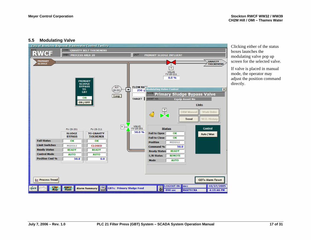
5.5 Modulating Valve Clicking either of the status boxes launches the modulating valve pop up screen for the selected valve.
If valve is placed in manual mode, the operator may adjust the position command directly.
July 7, 2006 – Rev. 1.0 PLC 21 Filter Press (GBT) System – SCADA System Operation Manual 17 of 31
Meyer Control Corporation Stockton RWCF WW32 / WW39 CH2M Hill / OMI – Thames Water
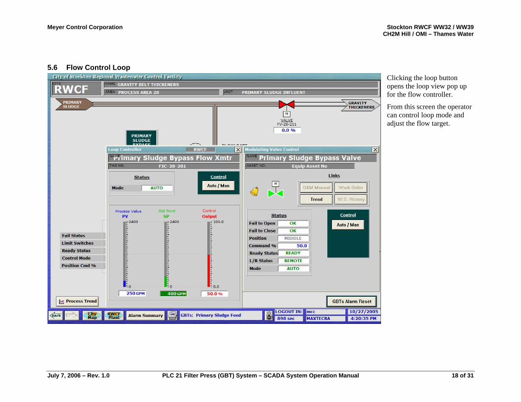
5.6 Flow Control Loop Clicking the loop button opens the loop view pop up for the flow controller.
From this screen the operator can control loop mode and adjust the flow target.
July 7, 2006 – Rev. 1.0 PLC 21 Filter Press (GBT) System – SCADA System Operation Manual 18 of 31
Meyer Control Corporation Stockton RWCF WW32 / WW39 CH2M Hill / OMI – Thames Water
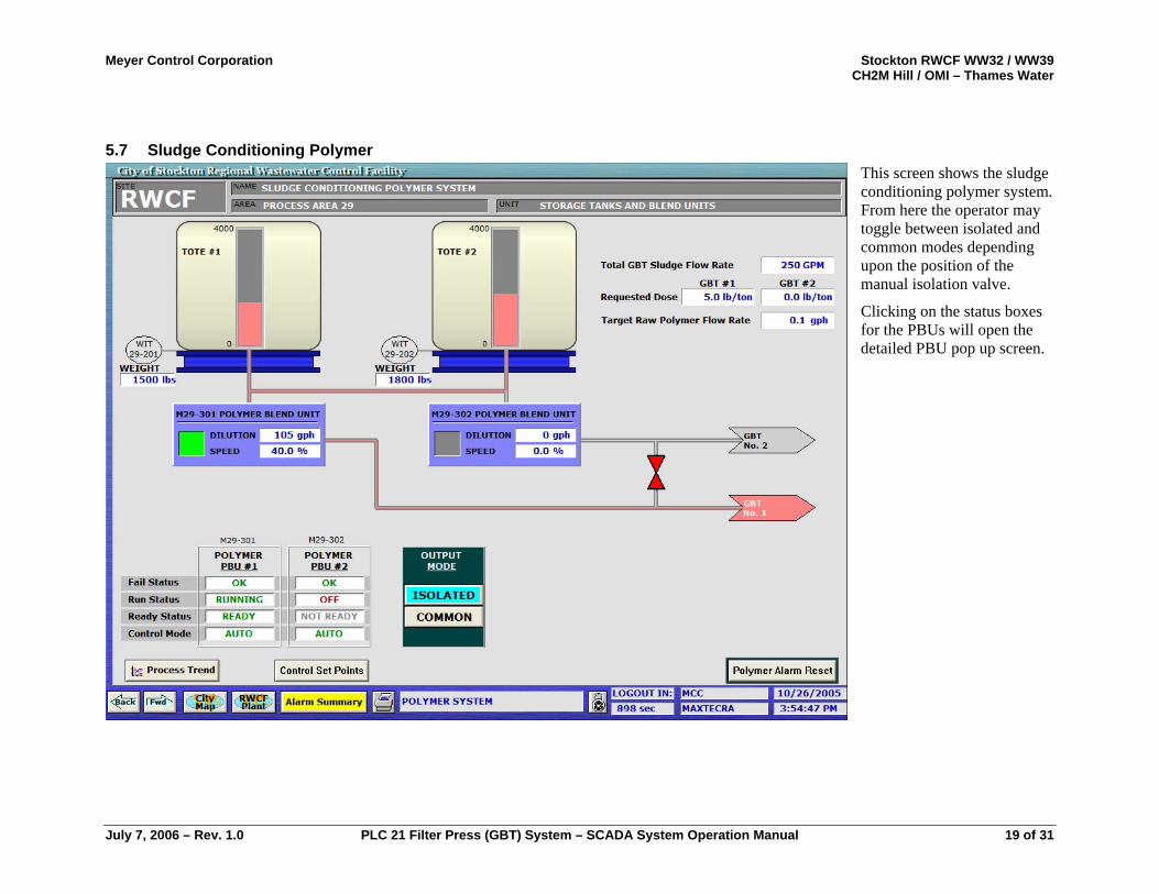
5.7 Sludge Conditioning Polymer This screen shows the sludge conditioning polymer system. From here the operator may toggle between isolated and common modes depending upon the position of the manual isolation valve.
Clicking on the status boxes for the PBUs will open the detailed PBU pop up screen.
July 7, 2006 – Rev. 1.0 PLC 21 Filter Press (GBT) System – SCADA System Operation Manual 19 of 31

Meyer Control Corporation Stockton RWCF WW32 / WW39 CH2M Hill / OMI – Thames Water
5.8 Polymer Blend Unit Pop Up The PBU pop up shows detailed information and allows an operator to control a polymer blend unit.
The On/Off button is disabled in automatic mode because the PBU will start and stop in response to GBT ready status.
The operator adjusts the desired polymer concentration in either auto or manual mode.
In manual mode the operator starts and stops the PBU and sets the desired raw polymer flow rate.
July 7, 2006 – Rev. 1.0 PLC 21 Filter Press (GBT) System – SCADA System Operation Manual 20 of 31
Meyer Control Corporation Stockton RWCF WW32 / WW39 CH2M Hill / OMI – Thames Water
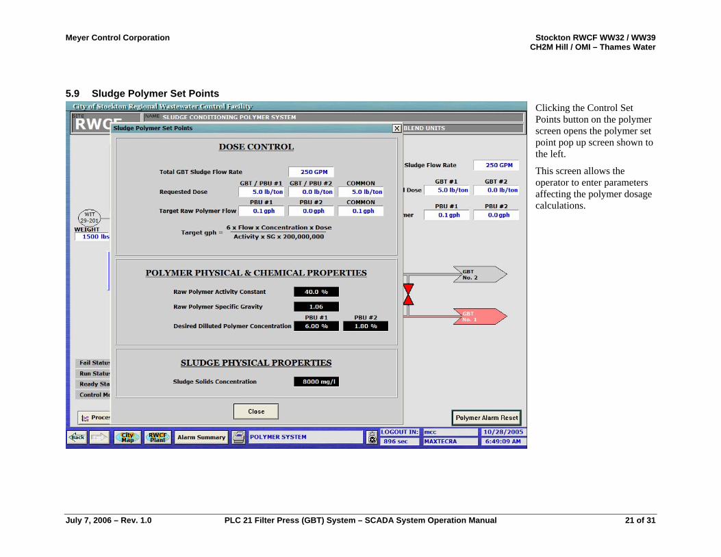
5.9 Sludge Polymer Set Points Clicking the Control Set Points button on the polymer screen opens the polymer set point pop up screen shown to the left.
This screen allows the operator to enter parameters affecting the polymer dosage calculations.
July 7, 2006 – Rev. 1.0 PLC 21 Filter Press (GBT) System – SCADA System Operation Manual 21 of 31
Meyer Control Corporation Stockton RWCF WW32 / WW39 CH2M Hill / OMI – Thames Water
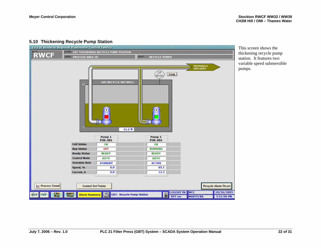
5.10 Thickening Recycle Pump Station This screen shows the thickening recycle pump station. It features two variable speed submersible pumps.
July 7, 2006 – Rev. 1.0 PLC 21 Filter Press (GBT) System – SCADA System Operation Manual 22 of 31
Meyer Control Corporation Stockton RWCF WW32 / WW39 CH2M Hill / OMI – Thames Water
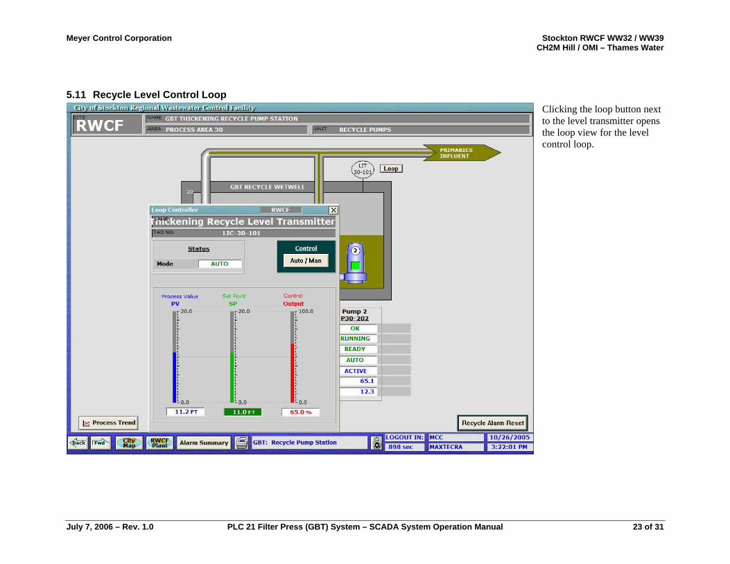
5.11 Recycle Level Control Loop Clicking the loop button next to the level transmitter opens the loop view for the level control loop.
July 7, 2006 – Rev. 1.0 PLC 21 Filter Press (GBT) System – SCADA System Operation Manual 23 of 31
Meyer Control Corporation Stockton RWCF WW32 / WW39 CH2M Hill / OMI – Thames Water
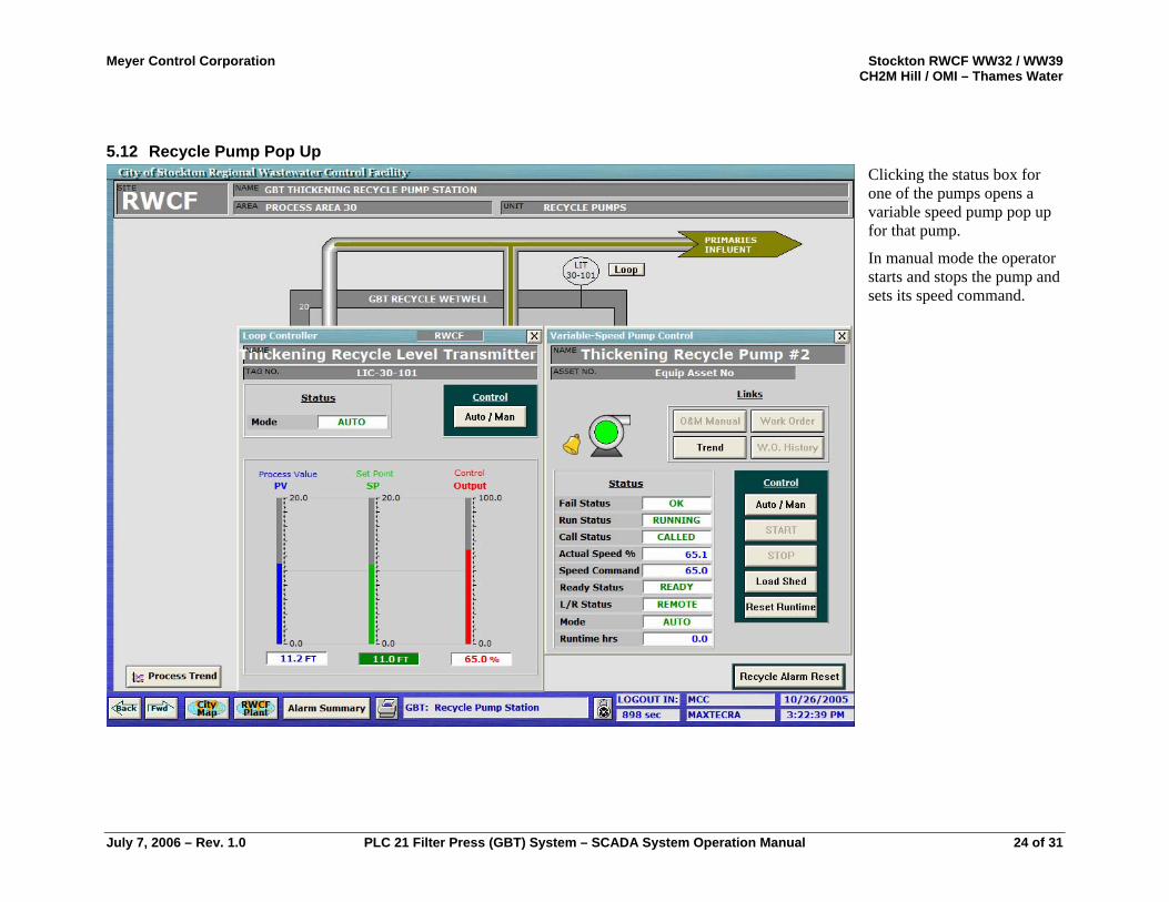
5.12 Recycle Pump Pop Up Clicking the status box for one of the pumps opens a variable speed pump pop up for that pump.
In manual mode the operator starts and stops the pump and sets its speed command.
July 7, 2006 – Rev. 1.0 PLC 21 Filter Press (GBT) System – SCADA System Operation Manual 24 of 31
Meyer Control Corporation Stockton RWCF WW32 / WW39 CH2M Hill / OMI – Thames Water
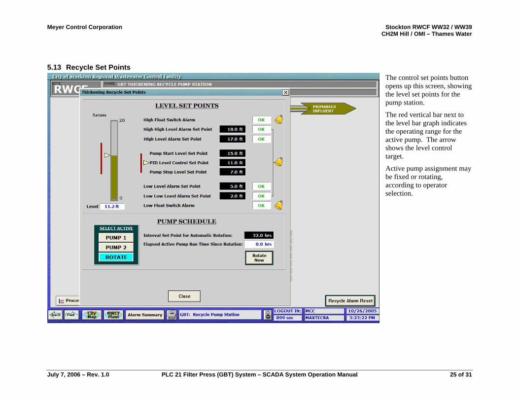
5.13 Recycle Set Points The control set points button opens up this screen, showing the level set points for the pump station.
The red vertical bar next to the level bar graph indicates the operating range for the active pump. The arrow shows the level control target.
Active pump assignment may be fixed or rotating, according to operator selection.
July 7, 2006 – Rev. 1.0 PLC 21 Filter Press (GBT) System – SCADA System Operation Manual 25 of 31
Meyer Control Corporation Stockton RWCF WW32 / WW39 CH2M Hill / OMI – Thames Water
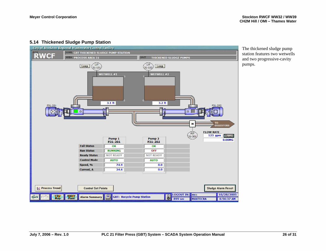
5.14 Thickened Sludge Pump Station The thickened sludge pump station features two wetwells and two progressive-cavity pumps.
July 7, 2006 – Rev. 1.0 PLC 21 Filter Press (GBT) System – SCADA System Operation Manual 26 of 31
Meyer Control Corporation Stockton RWCF WW32 / WW39 CH2M Hill / OMI – Thames Water
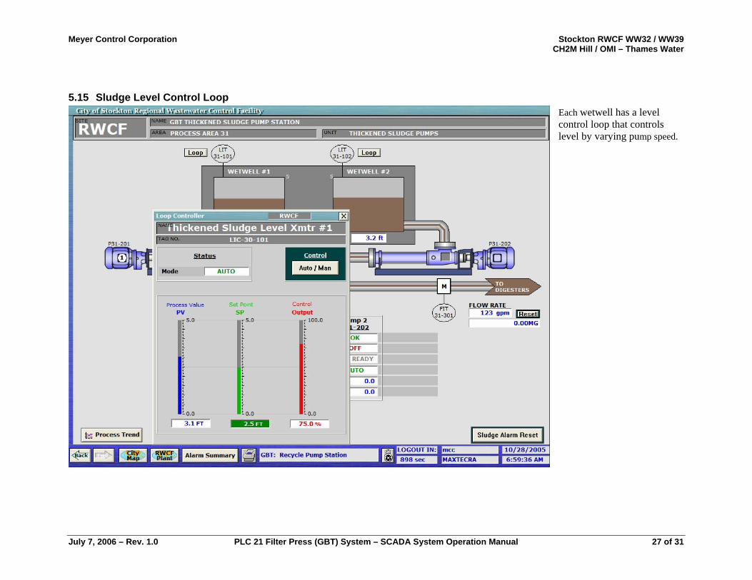
5.15 Sludge Level Control Loop Each wetwell has a level control loop that controls level by varying pump speed.
July 7, 2006 – Rev. 1.0 PLC 21 Filter Press (GBT) System – SCADA System Operation Manual 27 of 31
Meyer Control Corporation Stockton RWCF WW32 / WW39 CH2M Hill / OMI – Thames Water
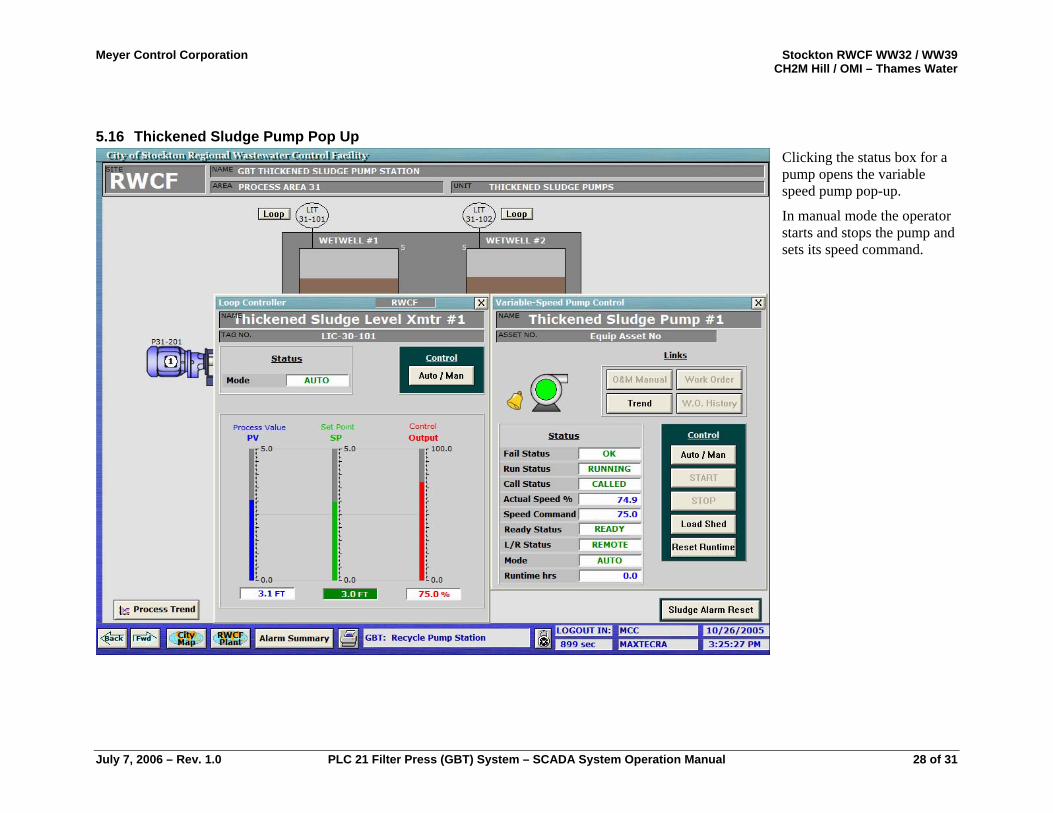
5.16 Thickened Sludge Pump Pop Up Clicking the status box for a pump opens the variable speed pump pop-up.
In manual mode the operator starts and stops the pump and sets its speed command.
July 7, 2006 – Rev. 1.0 PLC 21 Filter Press (GBT) System – SCADA System Operation Manual 28 of 31
Meyer Control Corporation Stockton RWCF WW32 / WW39 CH2M Hill / OMI – Thames Water
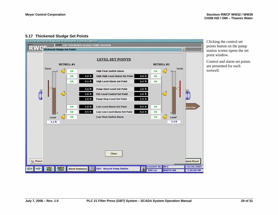
5.17 Thickened Sludge Set Points Clicking the control set points button on the pump station screen opens the set point window.
Control and alarm set points are presented for each wetwell.
July 7, 2006 – Rev. 1.0 PLC 21 Filter Press (GBT) System – SCADA System Operation Manual 29 of 31
Meyer Control Corporation Stockton RWCF WW32 / WW39 CH2M Hill / OMI – Thames Water
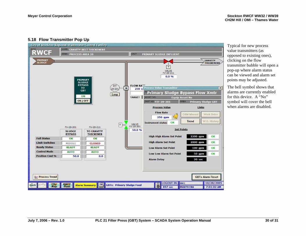
5.18 Flow Transmitter Pop Up Typical for new process value transmitters (as opposed to existing ones), clicking on the flow transmitter bubble will open a pop-up where alarm status can be viewed and alarm set points may be adjusted.
The bell symbol shows that alarms are currently enabled for this device. A “No” symbol will cover the bell when alarms are disabled.
July 7, 2006 – Rev. 1.0 PLC 21 Filter Press (GBT) System – SCADA System Operation Manual 30 of 31
Meyer Control Corporation Stockton RWCF WW32 / WW39 CH2M Hill / OMI – Thames Water
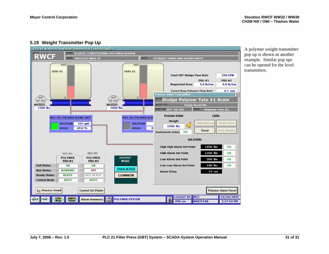
5.19 Weight Transmitter Pop Up A polymer weight transmitter pop up is shown as another example. Similar pop ups can be opened for the level transmitters.
July 7, 2006 – Rev. 1.0 PLC 21 Filter Press (GBT) System – SCADA System Operation Manual 31 of 31