Platform Guide: VIPRION® 4400 Series · The VIPRION® 4400 Series Platform About the platform...
98
Platform Guide: VIPRION ® 4400 Series MAN-0311-09
Transcript of Platform Guide: VIPRION® 4400 Series · The VIPRION® 4400 Series Platform About the platform...

Platform Guide: VIPRION® 4400 Series
MAN-0311-09

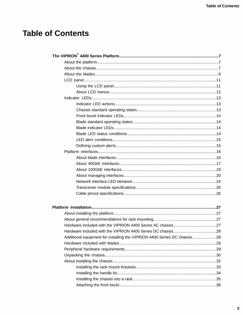
Table of Contents
The VIPRION®
4400 Series Platform..........................................................................................7
About the platform..............................................................................................................7
About the chassis...............................................................................................................7
About the blades................................................................................................................9
LCD panel........................................................................................................................11
Using the LCD panel.............................................................................................11
About LCD menus.................................................................................................12
Indicator LEDs.................................................................................................................13
Indicator LED actions............................................................................................13
Chassis standard operating states........................................................................13
Front bezel indicator LEDs....................................................................................14
Blade standard operating states............................................................................14
Blade indicator LEDs.............................................................................................14
Blade LED status conditions.................................................................................14
LED alert conditions..............................................................................................15
Defining custom alerts...........................................................................................15
Platform interfaces...........................................................................................................16
About blade interfaces...........................................................................................16
About 40GbE interfaces........................................................................................17
About 100GbE interfaces......................................................................................19
About managing interfaces....................................................................................20
Network interface LED behavior............................................................................24
Transceiver module specifications.........................................................................26
Cable pinout specifications....................................................................................26
Platform Installation.................................................................................................................27
About installing the platform.............................................................................................27
About general recommendations for rack mounting.........................................................27
Hardware included with the VIPRION 4400 Series AC chassis.......................................27
Hardware included with the VIPRION 4400 Series DC chassis.......................................28
Additional equipment for installing the VIPRION 4400 Series DC chassis......................28
Hardware included with blades........................................................................................29
Peripheral hardware requirements...................................................................................29
Unpacking the chassis.....................................................................................................30
About installing the chassis..............................................................................................32
Installing the rack mount brackets.........................................................................33
Installing the handle kit..........................................................................................34
Installing the chassis into a rack............................................................................35
Attaching the front bezel........................................................................................36
3
Table of Contents

About installing blades.....................................................................................................36
Removing a blank..................................................................................................37
Removing a blade.................................................................................................38
Installing a blade...................................................................................................39
Blade compatibility................................................................................................40
Blade performance in mixed clusters....................................................................41
About powering the VIPRION 4400 Series AC platform..................................................42
Powering the AC platform......................................................................................42
About powering the VIPRION 4400 Series DC platform..................................................43
Additional equipment for powering the DC platform..............................................43
About grounding the chassis.................................................................................43
About connecting the DC power source................................................................44
Connecting the cables and other hardware.....................................................................45
About cluster management..............................................................................................46
Configuring the cluster IP address from the LCD..................................................47
Configuring the cluster IP address using the config utility.....................................48
Configuring the cluster IP address using tmsh......................................................49
Licensing the platform......................................................................................................49
Verifying blade availability................................................................................................49
Platform Maintenance...............................................................................................................51
About maintaining the platform........................................................................................51
About AC power supplies.................................................................................................51
Installing an AC power supply...............................................................................52
About DC power supplies.................................................................................................52
Installing a DC power supply.................................................................................54
About the fan tray.............................................................................................................54
Replacing the fan tray............................................................................................55
About the storage drives..................................................................................................56
Replacing a storage drive assembly on a B4300 blade........................................56
About the front bezel (with LCD component)...................................................................57
Replacing the front bezel.......................................................................................57
Environmental Guidelines........................................................................................................59
General environmental guidelines....................................................................................59
Guidelines for the AC-powered platform..........................................................................60
Guidelines for the DC-powered platform..........................................................................60
NEBS platform guidelines................................................................................................61
Platform airflow diagram..................................................................................................61
Platform Specifications............................................................................................................63
General specifications for system features......................................................................63
VIPRION B4100/4200 Series blade hardware specifications..........................................63
VIPRION B4300/B4400 Series blade hardware specifications........................................64
4
Table of Contents

Chassis hardware specifications......................................................................................64
Chassis environmental operating specifications..............................................................65
About AC power requirements.........................................................................................65
About AC power cables.........................................................................................66
AC power redundancy provisioning.......................................................................66
AC platform power consumption (low-line input)...................................................66
AC platform power consumption (high-line input)..................................................67
DC power requirements...................................................................................................68
DC power redundancy provisioning......................................................................68
DC platform power consumption...........................................................................68
NEBS-compliant VIPRION system configurations...........................................................69
Safety requirements.........................................................................................................69
EMC requirements...........................................................................................................70
Acoustic, airflow, and altitude specifications....................................................................71
China RoHS Requirements......................................................................................................73
Hazardous substance levels for China.............................................................................73
Repackaging Guidelines..........................................................................................................79
About repackaging the platform.......................................................................................79
Repackaging the chassis.................................................................................................79
Repackaging a blade.......................................................................................................82
Returned Material Data Security Statement...........................................................................87
About returned material data security..............................................................................87
About memory technologies used in F5 equipment.........................................................87
Volatile memory.....................................................................................................87
Battery-backed volatile memory............................................................................87
Non-volatile memory.............................................................................................87
About removing data from F5 components......................................................................88
Removing sensitive data from storage drives........................................................88
Removing IP address data from Always-On Management....................................89
Removing sensitive data from an internal hardware security module (HSM)........89
Legal Notices............................................................................................................................91
Legal Notices...................................................................................................................91
5
Table of Contents

6
Table of Contents

The VIPRION® 4400 Series Platform
About the platform
The VIPRION® 4400 Series system provides you with the flexibility and feature-rich capabilities of F5®
products on a powerful and highly-extensible hardware platform.With this platform, you install and configuremultiple F5 products using hot-swappable blades. This provides you with the ability to add, remove, orchange the platform's configuration to best fit your network. Many components are available for you to add,remove, or change including the blades, power supplies, fan tray, LCD panel, and more. This configurationallows for an extremely robust and flexible system that can manage large amounts of application traffic,and remain operational even if one of its components goes offline.
VIPRION platforms include two types of components: blades, which provide the hardware and softwareneeded to manage network traffic, and a chassis, which houses the blades.
Important: The chassis and blades are shipped in separate boxes. The blades are not designed to be shippedinside a chassis.
Although the VIPRION 4400 Series platform is highly extensible and designed to be easy to implement,familiarity with the platform components can help ensure that you install and integrate the platformsuccessfully and effectively.
About the chassis
The chassis is the housing unit that contains all of the components necessary for the VIPRION® 4400 Seriesplatform to operate effectively.
The VIPRION 4400 Series includes two chassis models: the VIPRION C4400 and the VIPRION C4480.The two chassis models appear identical, with the exception of the model number on the front. The VIPRIONC4480 is designed to support higher bandwidth blades, such as B4300 and B4400 Series blades.
The VIPRION C4400 and C4480 chassis and B4100, B4200, B4300, and B4400 Series blades are availablein DC-powered Network Equipment-Building System (NEBS) compliant versions. For a system to becompletely NEBS-compliant, you must use a NEBS-compliant chassis and blades.
1. Indicator LEDs (system and power status)2. LCD display3. LCD control buttons
Figure 1: Front view of a VIPRION C4400 chassis with four blades and front bezel (with LCD panel)attached
1. Indicator LEDs (system and power status)2. LCD display3. LCD control buttons
Figure 2: Front view of a VIPRION C4480 chassis with four blades and front bezel (with LCD panel)attached
8
The VIPRION® 4400 Series Platform

The back of the AC-powered chassis includes four AC power receptacles.
Figure 3: Back view of the AC chassis
The back of the DC-powered chassis includes two DC power block terminals.
Figure 4: Back view of the DC chassis
About the blades
A blade is the primary component that handles the traffic management within the VIPRION® platform. Youcan install up to four blades in a VIPRION 4400 Series chassis. These blades comprise a group, known asa cluster. The chassis includes blanks in the slots where blades are not installed.
Blanks must be installed in all unused slots, as they help ensure proper airflow within the chassis and EMIcompliance of the unit.
9
Platform Guide: VIPRION® 4400 Series
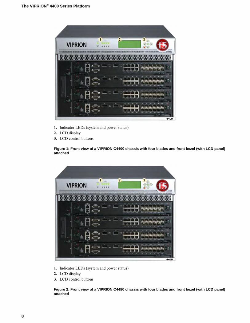
You can use B4100, B4200, or B4300 Series blades in a VIPRION 4400 Series chassis. You can use onlyB4200, B4300, and B4400 Series blades in the VIPRION 4480 chassis. For optimum performance, youshould use B4300 or B4400 Series blades only in a VIPRION 4480 chassis.
Note: You should not mix B4300 or B4400 blades with other blade types in a chassis.
Figure 5: Front view of the B4100 Series blade
1. Compression screw2. Blade indicator LEDs3. Management port4. USB ports (2)5. Console port6. Serial (hard-wired) failover port7. XFP ports (2)8. 10/100/1000 interfaces (8)9. SFP ports (12)
Figure 6: Front view of the B4200 Series blade
1. Compression screw2. Blade indicator LEDs3. Management port4. USB ports (2)5. Console port6. Serial (hard-wired) failover port7. 10/100/1000 ports (4)8. SFP+ ports (8)
Figure 7: Front view of a B4300 Series blade
1. Compression screw2. Blade indicator LEDs3. Management port4. USB ports (2)5. Console port
10
The VIPRION® 4400 Series Platform
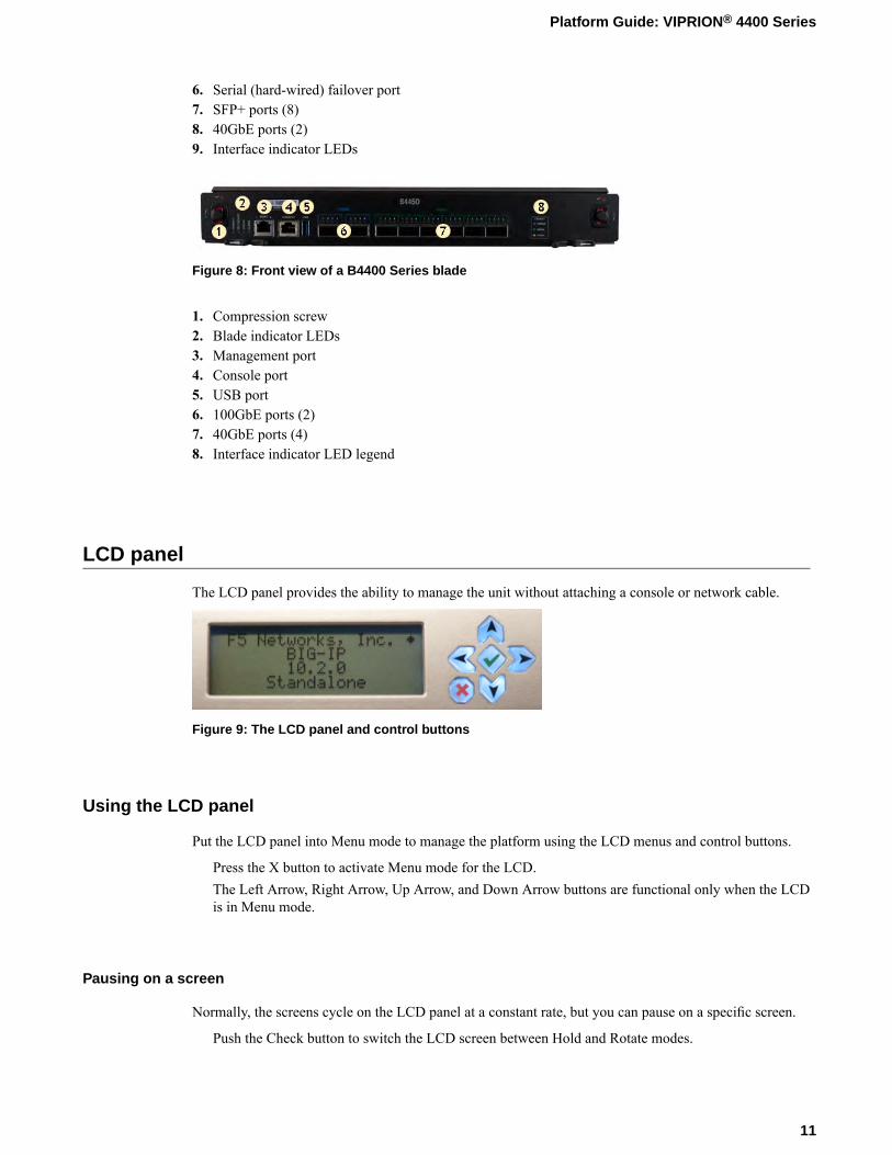
6. Serial (hard-wired) failover port7. SFP+ ports (8)8. 40GbE ports (2)9. Interface indicator LEDs
Figure 8: Front view of a B4400 Series blade
1. Compression screw2. Blade indicator LEDs3. Management port4. Console port5. USB port6. 100GbE ports (2)7. 40GbE ports (4)8. Interface indicator LED legend
LCD panel
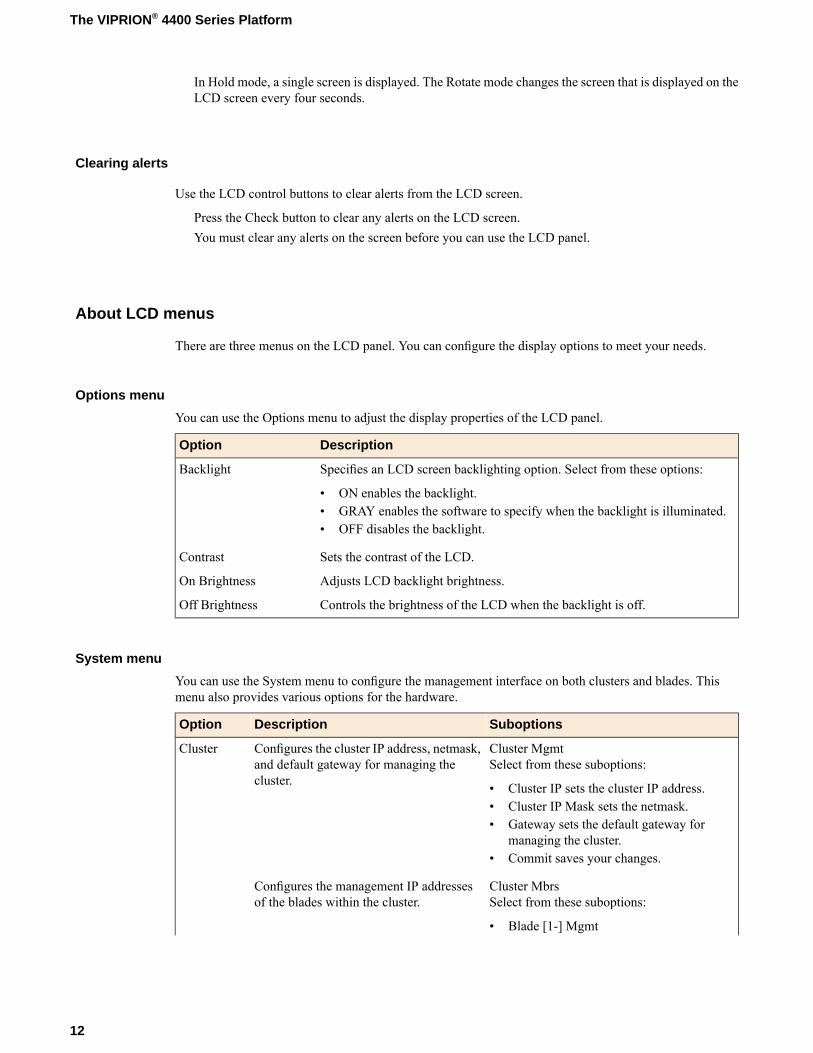
The LCD panel provides the ability to manage the unit without attaching a console or network cable.
Figure 9: The LCD panel and control buttons
Using the LCD panel
Put the LCD panel into Menu mode to manage the platform using the LCD menus and control buttons.
Press the X button to activate Menu mode for the LCD.The Left Arrow, Right Arrow, Up Arrow, and Down Arrow buttons are functional only when the LCDis in Menu mode.
Pausing on a screen
Normally, the screens cycle on the LCD panel at a constant rate, but you can pause on a specific screen.
Push the Check button to switch the LCD screen between Hold and Rotate modes.
11
Platform Guide: VIPRION® 4400 Series
In Hold mode, a single screen is displayed. The Rotate mode changes the screen that is displayed on theLCD screen every four seconds.
Clearing alerts
Use the LCD control buttons to clear alerts from the LCD screen.
Press the Check button to clear any alerts on the LCD screen.You must clear any alerts on the screen before you can use the LCD panel.
About LCD menus
There are three menus on the LCD panel. You can configure the display options to meet your needs.
Options menu
You can use the Options menu to adjust the display properties of the LCD panel.
DescriptionOption
Specifies an LCD screen backlighting option. Select from these options:Backlight
• ON enables the backlight.• GRAY enables the software to specify when the backlight is illuminated.• OFF disables the backlight.
Sets the contrast of the LCD.Contrast
Adjusts LCD backlight brightness.On Brightness
Controls the brightness of the LCD when the backlight is off.Off Brightness
System menu
You can use the System menu to configure the management interface on both clusters and blades. Thismenu also provides various options for the hardware.
SuboptionsDescriptionOption
Cluster MgmtSelect from these suboptions:
Configures the cluster IP address, netmask,and default gateway for managing thecluster.
Cluster
• Cluster IP sets the cluster IP address.• Cluster IP Mask sets the netmask.• Gateway sets the default gateway for
managing the cluster.• Commit saves your changes.
Cluster MbrsSelect from these suboptions:
Configures the management IP addressesof the blades within the cluster.
• Blade [1-] Mgmt
12
The VIPRION® 4400 Series Platform

SuboptionsDescriptionOption• BladeMgmt IP sets the management IP
address of the selected blade within thecluster.
• Commit saves your changes.
Screens menu
You can use the Screens menu to specify the information that is displayed on the default screens.
DescriptionOption
Displays the date and time.DateScreen
Displays the information screen menu.InfoScreen
Displays product version information.VersionScreen
Indicator LEDs
The VIPRION® 4400 Series platform includes indicator LEDs in two locations: on the LCD panel and onthe individual blades. On the LCD panel, the LEDs provide information about platform power, blade alarms,and status.
On the blades, the LEDs indicate whether the blade is a primary or secondary blade, and show alarm andblade status. The Alarm LED status for blades is also displayed in the corresponding LED on the LCDpanel.
Indicator LED actions
The behavior of the LEDs indicate system or component status.
DescriptionAction
LED is not lit and does not display any color.Off (none)
LED is lit and does not blink.Solid
LED turns on and off at a regular frequency.Blinking
LED turns on and off with an irregular frequency and might appear solid.Intermittent
Chassis standard operating states
The chassis LEDs indicate the operating state of a chassis.
Alarm LEDStatus LEDSystem state
Off/NoneGreen solidActive/Standalone
Off/NoneGreen solidStandby
Off/NoneOff/NonePowered off
13
Platform Guide: VIPRION® 4400 Series
Front bezel indicator LEDs
The front bezel LEDs indicate the overall operating status of the chassis.
StatusLED
Indicates that a power supply is present and operational (green), present butnon-functioning (amber), or does not have a power supply connected (off). The
Power
chassis front bezel has one LED per power supply. There are eight power supplyLEDs; however, only the first four are functional in the four-slot chassis. The chassisfront bezel has four power supply LEDs: one LED per supply.
Indicates the overall state of the chassis: functional (green) or experiencing errors(amber).
Status
Indicates both blade and chassis alarms. If a blade indicates an alarm condition, thechassis Alarm LED mirrors that state. In situations where more than one blade isgenerating an alarm, the chassis Alarm LED displays the most severe alarm status.
Alarm
Blade standard operating states
The blade LEDs indicate the operating state of a blade.
Note: On power up, the Status LED of each blade turns amber. When the BIG-IP® software bootssuccessfully, the Status LED changes to green.
Alarm LEDStatus LEDSecondary LEDPrimary LEDSystem state
Off/NoneGreen solidOff/NoneOff/NoneActive mode
Off/NoneOff/NoneOff/NoneOff/NonePowered off
Blade indicator LEDs
The blade LEDs indicate whether the blade is a primary or secondary blade, and show alarm and bladestatus.
StatusLED
Indicates that the blade is a primary blade for a cluster.Primary
Indicates that the blade is a secondary blade for a cluster.Secondary
Indicates the state of the system.Status
Indicates a non-specific alert level. Use SNMP traps, system logs, or the LCD displayfor more information.
Alarm
Blade LED status conditions
The blade LEDs indicate specific operating conditions, such as high availability (HA) status, or when ablade is shut down, reset, or not properly seated.
14
The VIPRION® 4400 Series Platform
Alarm LEDStatus LEDSecondary LEDPrimary LEDBlade state
Off/NoneGreen solidOff/NoneGreen solidBlade is fully functionaland operating as theprimary in a highavailability (HA)configuration
Off/NoneGreen solidAmber solidOff/NoneBlade is fully functionaland operating as asecondary in a highavailability (HA)configuration
Off/NoneGreen blinkingGreen blinkingGreen blinkingUser-initiated bladepower down
Red solidAmber blinkingAmber blinkingAmber blinkingBlade shut down due tothermal overtemp limit
Red solidAmber solidAmber blinkingAmber blinkingBlade not seated properly
LED alert conditions
The Alarm LED indicates when there is an alert condition on the system.
Note: The Alarm LED might continue to display until alerts are cleared using the LCD panel.
DescriptionAction
Alarm LED behaviorSystem situation
Red blinkingEmergency
Red solidAlert or Critical
Amber blinkingError
Amber solidWarning
Defining custom alerts
The /etc/alertd/alert.conf and the /config/user_alert.conf files on the VIPRION® systemdefine alerts that cause the indicators to change. The /etc/alertd/alert.conf file defines standardsystem alerts, and the /config/user_alert.conf file defines custom settings. You should edit only the/config/user_alert.conf file.
1. Open a command prompt on the system.2. Change to the /config directory.
cd /config
3. Using a text editor, such as vi or Pico, open the /config/user_alert.conf file.
15
Platform Guide: VIPRION® 4400 Series
4. Add these lines to the end of the file:
alert BIGIP_MCPD_MCPDERR_POOL_MEMBER_MON_DOWN "Pool member (.*?):(.*?) monitorstatus down."{snmptrap OID=".1.3.6.1.4.1.3375.2.4.0.10";lcdwarn description="Node down" priority="1"
}alert BIGIP_MCPD_MCPDERR_NODE_ADDRESS_MON_DOWN "Node (.*?) monitor statusdown." {snmptrap OID=".1.3.6.1.4.1.3375.2.4.0.12";lcdwarn description="Node address down" priority="1"
}alert BIGIP_MCPD_MCPDERR_POOL_MEMBER_MON_UP "Pool member (.*?):(.*?) monitorstatus up."{snmptrap OID=".1.3.6.1.4.1.3375.2.4.0.11"
}alert BIGIP_MCPD_MCPDERR_NODE_ADDRESS_MON_UP "Node (.*?) monitor status up."
{snmptrap OID=".1.3.6.1.4.1.3375.2.4.0.13"
}
5. Save the file and exit the text editor.The front panel LEDs now indicate when a node is down.
Platform interfaces
Every platform includes multiple interfaces. The exact number of interfaces that are on the system dependson the platform type.
Each interface on the platform has a set of properties that you can configure, such as enabling or disablingthe interface, setting the requested media type and duplex mode, and configuring flow control.
About blade interfaces
B4100 and B4200 Series blades
The B4100 and B4200 Series blades have SFP optical interfaces, RJ45 10/100/1000 copper interfaces, and10GbE XFP or 10GbE SFP+ optical interfaces that are connected internally. Each set of interfaces isnumbered from x.1 through x.n, with each group of media types designated by a different prefix. It isimportant to note some facts about these interfaces:
• The RJ45 connectors can each support 10/100/1000Mbit Ethernet speed, except where otherwise noted.• The SFP connectors can each support 1000 Mbit speed with a 1GbE transceiver module installed or
10/100/1000Mbit speeds with an F5®-branded copper SFP module.• The XFP connectors can each support 10G speed with an F5-branded XFP transceiver module installed.
Only B4100 Series blades include XFP interfaces.• The SFP+ connectors can each support 10G speed with an F5-branded SFP+ transceiver module or 1000
Mbit speed with an F5-branded SFP 1GbE transceiver module installed.
16
The VIPRION® 4400 Series Platform
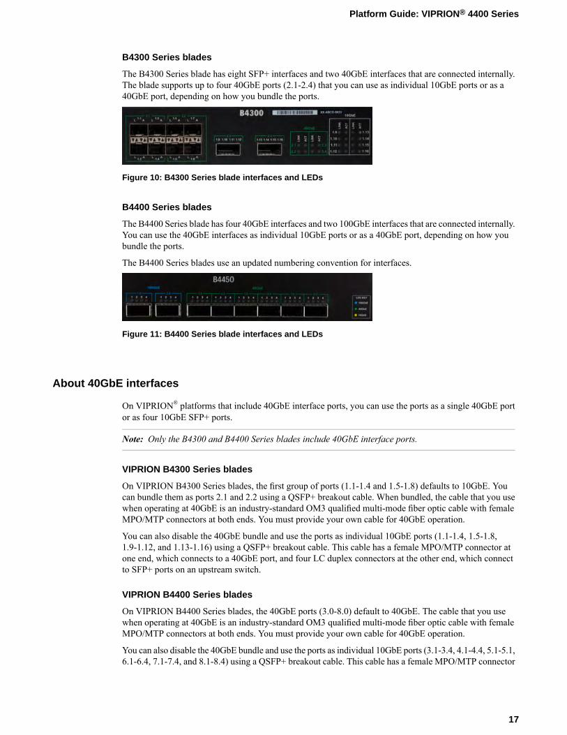
B4300 Series blades
The B4300 Series blade has eight SFP+ interfaces and two 40GbE interfaces that are connected internally.The blade supports up to four 40GbE ports (2.1-2.4) that you can use as individual 10GbE ports or as a40GbE port, depending on how you bundle the ports.
Figure 10: B4300 Series blade interfaces and LEDs
B4400 Series blades
The B4400 Series blade has four 40GbE interfaces and two 100GbE interfaces that are connected internally.You can use the 40GbE interfaces as individual 10GbE ports or as a 40GbE port, depending on how youbundle the ports.
The B4400 Series blades use an updated numbering convention for interfaces.
Figure 11: B4400 Series blade interfaces and LEDs
About 40GbE interfaces
On VIPRION® platforms that include 40GbE interface ports, you can use the ports as a single 40GbE portor as four 10GbE SFP+ ports.
Note: Only the B4300 and B4400 Series blades include 40GbE interface ports.
VIPRION B4300 Series blades
On VIPRION B4300 Series blades, the first group of ports (1.1-1.4 and 1.5-1.8) defaults to 10GbE. Youcan bundle them as ports 2.1 and 2.2 using a QSFP+ breakout cable. When bundled, the cable that you usewhen operating at 40GbE is an industry-standard OM3 qualified multi-mode fiber optic cable with femaleMPO/MTP connectors at both ends. You must provide your own cable for 40GbE operation.
You can also disable the 40GbE bundle and use the ports as individual 10GbE ports (1.1-1.4, 1.5-1.8,1.9-1.12, and 1.13-1.16) using a QSFP+ breakout cable. This cable has a female MPO/MTP connector atone end, which connects to a 40GbE port, and four LC duplex connectors at the other end, which connectto SFP+ ports on an upstream switch.
VIPRION B4400 Series blades
On VIPRION B4400 Series blades, the 40GbE ports (3.0-8.0) default to 40GbE. The cable that you usewhen operating at 40GbE is an industry-standard OM3 qualified multi-mode fiber optic cable with femaleMPO/MTP connectors at both ends. You must provide your own cable for 40GbE operation.
You can also disable the 40GbE bundle and use the ports as individual 10GbE ports (3.1-3.4, 4.1-4.4, 5.1-5.1,6.1-6.4, 7.1-7.4, and 8.1-8.4) using a QSFP+ breakout cable. This cable has a female MPO/MTP connector
17
Platform Guide: VIPRION® 4400 Series
at one end, which connects to a 40GbE port, and four LC duplex connectors at the other end, which connectto SFP+ ports on an upstream switch.
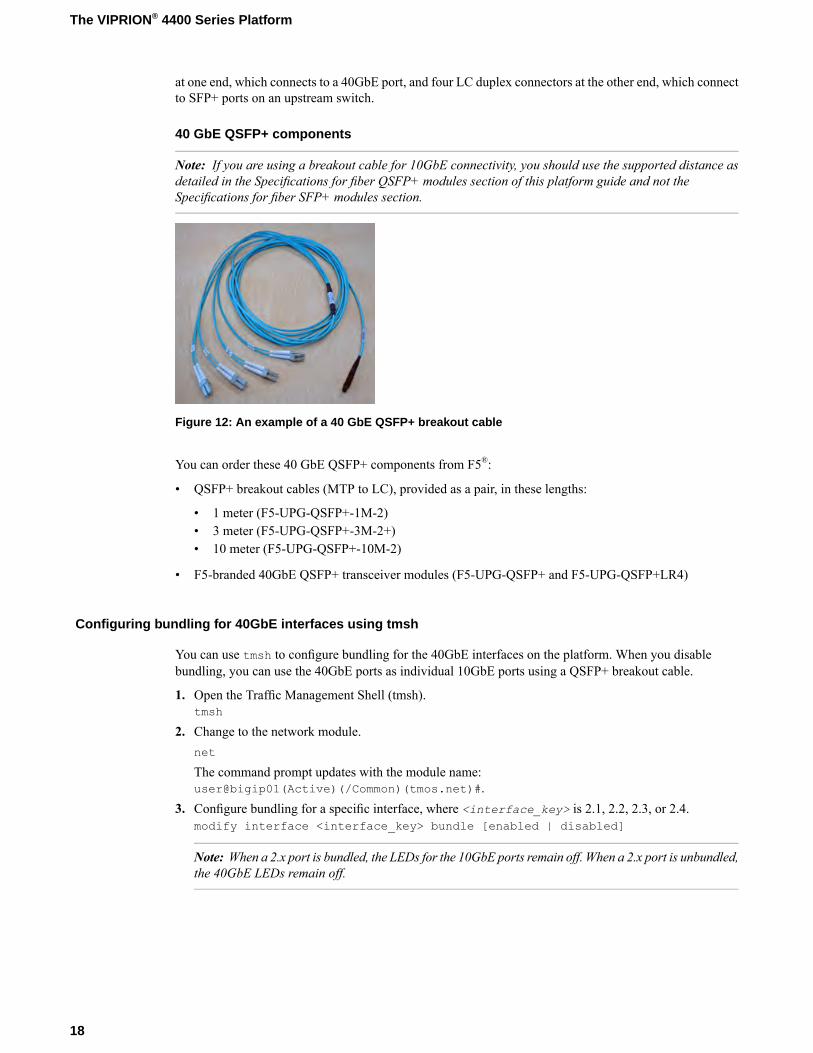
40 GbE QSFP+ components
Note: If you are using a breakout cable for 10GbE connectivity, you should use the supported distance asdetailed in the Specifications for fiber QSFP+ modules section of this platform guide and not theSpecifications for fiber SFP+ modules section.
Figure 12: An example of a 40 GbE QSFP+ breakout cable
You can order these 40 GbE QSFP+ components from F5®:
• QSFP+ breakout cables (MTP to LC), provided as a pair, in these lengths:
• 1 meter (F5-UPG-QSFP+-1M-2)• 3 meter (F5-UPG-QSFP+-3M-2+)• 10 meter (F5-UPG-QSFP+-10M-2)
• F5-branded 40GbE QSFP+ transceiver modules (F5-UPG-QSFP+ and F5-UPG-QSFP+LR4)
Configuring bundling for 40GbE interfaces using tmsh
You can use tmsh to configure bundling for the 40GbE interfaces on the platform. When you disablebundling, you can use the 40GbE ports as individual 10GbE ports using a QSFP+ breakout cable.
1. Open the Traffic Management Shell (tmsh).tmsh
2. Change to the network module.net
The command prompt updates with the module name:user@bigip01(Active)(/Common)(tmos.net)#.
3. Configure bundling for a specific interface, where <interface_key> is 2.1, 2.2, 2.3, or 2.4.modify interface <interface_key> bundle [enabled | disabled]
Note: When a 2.x port is bundled, the LEDs for the 10GbE ports remain off. When a 2.x port is unbundled,the 40GbE LEDs remain off.
18
The VIPRION® 4400 Series Platform

Configuring bundling for 40GbE interfaces using the Configuration utility
You can use the Configuration utility to configure bundling for the 40GbE interfaces on the platform.Whenyou disable bundling, you can use the 40GbE ports as individual 10GbE ports using a QSFP+ breakoutcable.
1. On the Main tab, click Network > Interfaces.This displays the list of available interfaces.
2. Click an interface name.The properties screen for that interface opens.
3. From the Bundled list, select whether to enable or disable bundling.4. Click Update.
About 100GbE interfaces
On platforms that include 100GbE interface ports, you can use only F5-branded 100GbEQSFP28 transceivermodules in those ports.
When a 100GbE interface operates at either 40GbE and 100GbE speeds, it is considered to be bundled.
VIPRION B4400 Series blades
On VIPRION B4400 Series blades, the 100GbE ports (1.0 and 2.0) default to 100GbE. The cable that youuse when operating at 100GbE with 100GBASE-SR4 transceiver modules is an industry-standard OM4qualified multi-mode fiber optic cable with female MPO/MTP connectors at both ends. The cable that youuse with 100GBASE-LR4 transceiver modules is an industry-standard SMF fiber optic cable with LC duplexconnectors and a reach of up to 10km. Youmust provide your own cable and F5-branded QSFP28 transceivermodules for 100GbE operation.
Configuring bundling for 100GbE interfaces using tmsh
You can use tmsh to configure bundling for the 100GbEQSFP28 interfaces on the platform at either 100GbEor 40GbE speeds.
1. Open the Traffic Management Shell (tmsh).tmsh
2. Change to the network module.net
The command prompt updates with the module name:user@bigip01(Active)(/Common)(tmos.net)#.
3. Configure bundling for a specific interface using this syntax.modify interface <interface_key> bundle [enabled | disabled] bundle-speed[100G | 40G | not-supported]
Note: The default value of bundle-speed is determined by the interface type. Unbundled interfaceshave bundle-speed set to not-supported.
19
Platform Guide: VIPRION® 4400 Series
Configuring FEC for 100GbE interfaces using tmsh
If your upstream switch does not support Reed-Solomon Forward Error Correction (RS-FEC), you can usetmsh to disable it for the 100GbE interfaces on your platform.
Note: RS-FEC is intended to be enabled with 100GBASE-SR links and disabled for 100GBASE-LR4 links.
1. Open the Traffic Management Shell (tmsh).tmsh
2. Change to the network module.net
The command prompt updates with the module name:user@bigip01(Active)(/Common)(tmos.net)#.
3. Configure FEC for a specific interface using this syntax.modify interface <interface_key> forward-error-correction [enabled | disabled]
About managing interfaces
You can use tmsh or the Configuration utility to configure platform interfaces.
Viewing the status of a specific interface using tmsh
You can use tmsh to view the status of a specific interface on a platform.
1. Open the Traffic Management Shell (tmsh).tmsh
2. Change to the network module.net
The command prompt updates with the module name:user@bigip01(Active)(/Common)(tmos.net)#.
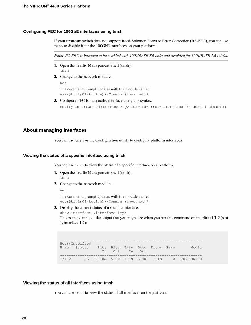
3. Display the current status of a specific interface.show interface <interface_key>This is an example of the output that you might see when you run this command on interface 1/1.2 (slot1, interface 1.2):
----------------------------------------------------------------Net::InterfaceName Status Bits Bits Pkts Pkts Drops Errs Media
In Out In Out----------------------------------------------------------------1/1.2 up 637.8G 5.8M 1.1G 5.7K 1.1G 0 10000SR-FD
Viewing the status of all interfaces using tmsh
You can use tmsh to view the status of all interfaces on the platform.
20
The VIPRION® 4400 Series Platform
1. Open the Traffic Management Shell (tmsh).tmsh
2. Change to the network module.net
The command prompt updates with the module name:user@bigip01(Active)(/Common)(tmos.net)#.
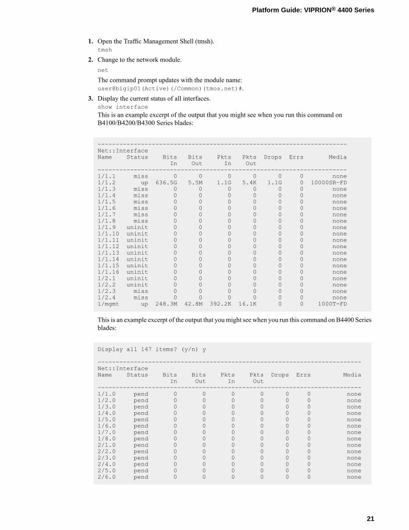
3. Display the current status of all interfaces.show interfaceThis is an example excerpt of the output that you might see when you run this command onB4100/B4200/B4300 Series blades:
---------------------------------------------------------------------Net::InterfaceName Status Bits Bits Pkts Pkts Drops Errs Media
In Out In Out---------------------------------------------------------------------1/1.1 miss 0 0 0 0 0 0 none1/1.2 up 636.5G 5.5M 1.1G 5.4K 1.1G 0 10000SR-FD1/1.3 miss 0 0 0 0 0 0 none1/1.4 miss 0 0 0 0 0 0 none1/1.5 miss 0 0 0 0 0 0 none1/1.6 miss 0 0 0 0 0 0 none1/1.7 miss 0 0 0 0 0 0 none1/1.8 miss 0 0 0 0 0 0 none1/1.9 uninit 0 0 0 0 0 0 none1/1.10 uninit 0 0 0 0 0 0 none1/1.11 uninit 0 0 0 0 0 0 none1/1.12 uninit 0 0 0 0 0 0 none1/1.13 uninit 0 0 0 0 0 0 none1/1.14 uninit 0 0 0 0 0 0 none1/1.15 uninit 0 0 0 0 0 0 none1/1.16 uninit 0 0 0 0 0 0 none1/2.1 uninit 0 0 0 0 0 0 none1/2.2 uninit 0 0 0 0 0 0 none1/2.3 miss 0 0 0 0 0 0 none1/2.4 miss 0 0 0 0 0 0 none1/mgmt up 248.3M 42.8M 392.2K 16.1K 0 0 1000T-FD
This is an example excerpt of the output that youmight see when you run this command on B4400 Seriesblades:
Display all 147 items? (y/n) y
-------------------------------------------------------------------------Net::InterfaceName Status Bits Bits Pkts Pkts Drops Errs Media
In Out In Out-------------------------------------------------------------------------1/1.0 pend 0 0 0 0 0 0 none1/2.0 pend 0 0 0 0 0 0 none1/3.0 pend 0 0 0 0 0 0 none1/4.0 pend 0 0 0 0 0 0 none1/5.0 pend 0 0 0 0 0 0 none1/6.0 pend 0 0 0 0 0 0 none1/7.0 pend 0 0 0 0 0 0 none1/8.0 pend 0 0 0 0 0 0 none2/1.0 pend 0 0 0 0 0 0 none2/2.0 pend 0 0 0 0 0 0 none2/3.0 pend 0 0 0 0 0 0 none2/4.0 pend 0 0 0 0 0 0 none2/5.0 pend 0 0 0 0 0 0 none2/6.0 pend 0 0 0 0 0 0 none
21
Platform Guide: VIPRION® 4400 Series
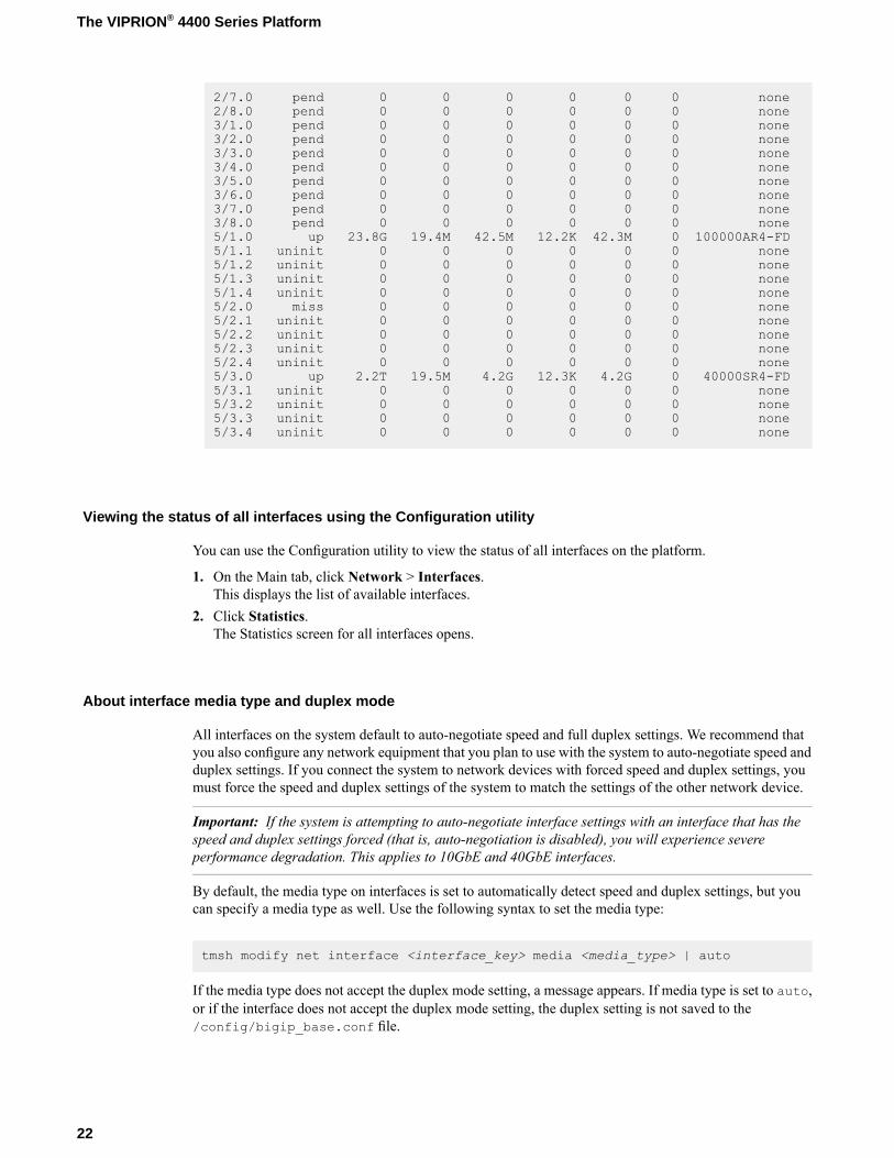
2/7.0 pend 0 0 0 0 0 0 none2/8.0 pend 0 0 0 0 0 0 none3/1.0 pend 0 0 0 0 0 0 none3/2.0 pend 0 0 0 0 0 0 none3/3.0 pend 0 0 0 0 0 0 none3/4.0 pend 0 0 0 0 0 0 none3/5.0 pend 0 0 0 0 0 0 none3/6.0 pend 0 0 0 0 0 0 none3/7.0 pend 0 0 0 0 0 0 none3/8.0 pend 0 0 0 0 0 0 none5/1.0 up 23.8G 19.4M 42.5M 12.2K 42.3M 0 100000AR4-FD5/1.1 uninit 0 0 0 0 0 0 none5/1.2 uninit 0 0 0 0 0 0 none5/1.3 uninit 0 0 0 0 0 0 none5/1.4 uninit 0 0 0 0 0 0 none5/2.0 miss 0 0 0 0 0 0 none5/2.1 uninit 0 0 0 0 0 0 none5/2.2 uninit 0 0 0 0 0 0 none5/2.3 uninit 0 0 0 0 0 0 none5/2.4 uninit 0 0 0 0 0 0 none5/3.0 up 2.2T 19.5M 4.2G 12.3K 4.2G 0 40000SR4-FD5/3.1 uninit 0 0 0 0 0 0 none5/3.2 uninit 0 0 0 0 0 0 none5/3.3 uninit 0 0 0 0 0 0 none5/3.4 uninit 0 0 0 0 0 0 none
Viewing the status of all interfaces using the Configuration utility
You can use the Configuration utility to view the status of all interfaces on the platform.
1. On the Main tab, click Network > Interfaces.This displays the list of available interfaces.
2. Click Statistics.The Statistics screen for all interfaces opens.
About interface media type and duplex mode
All interfaces on the system default to auto-negotiate speed and full duplex settings. We recommend thatyou also configure any network equipment that you plan to use with the system to auto-negotiate speed andduplex settings. If you connect the system to network devices with forced speed and duplex settings, youmust force the speed and duplex settings of the system to match the settings of the other network device.
Important: If the system is attempting to auto-negotiate interface settings with an interface that has thespeed and duplex settings forced (that is, auto-negotiation is disabled), you will experience severeperformance degradation. This applies to 10GbE and 40GbE interfaces.
By default, the media type on interfaces is set to automatically detect speed and duplex settings, but youcan specify a media type as well. Use the following syntax to set the media type:
tmsh modify net interface <interface_key> media <media_type> | auto
If the media type does not accept the duplex mode setting, a message appears. If media type is set to auto,or if the interface does not accept the duplex mode setting, the duplex setting is not saved to the/config/bigip_base.conf file.
22
The VIPRION® 4400 Series Platform
Important: Auto-MDI/MDIX functionality is retained when you manually configure an interface to usespecific speed and duplex settings. You can use either a straight-through cable or a crossover cable whenmedia settings are forced, and you will be able to successfully link to either DTE or DCE devices.
Valid media types
These media types are valid for the tmsh interface command.
Note: This platform might not support all of the media type options that are available in tmsh.
10GBaseLR full10BaseT half
10GBaseER full10BaseT full
10SFP+Cu full100BaseTX half
40GBaseSR4 full100BaseTX full
40GBaseLR4 full1000BaseT half
100GbaseSR4 full1000BaseT full
100GbaseLR4 full1000BaseSX full
auto1000BaseLX full
none1000BaseCX full
no-phy10GBaseT full
10GBaseSR full
Viewing valid media types for an interface
You can use tmsh to view the valid media types for an interface.
Note: This platform might not support all of the media type options that are available in tmsh.
1. Open the Traffic Management Shell (tmsh).tmsh
2. Change to the network module.net
The command prompt updates with the module name:user@bigip01(Active)(/Common)(tmos.net)#.
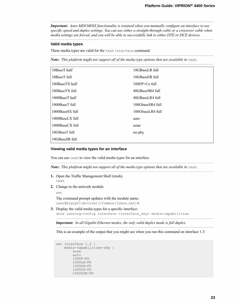
3. Display the valid media types for a specific interface:show running-config interface <interface_key> media-capabilities
Important: In all Gigabit Ethernet modes, the only valid duplex mode is full duplex.
This is an example of the output that you might see when you run this command on interface 1.3:
net interface 1.3 {media-capabilities-sfp {
noneauto1000T-FD1000LX-FD1000SX-FD1000CX-FD10000SR-FD
23
Platform Guide: VIPRION® 4400 Series
10000LR-FD10000SFPCU-FD
}}
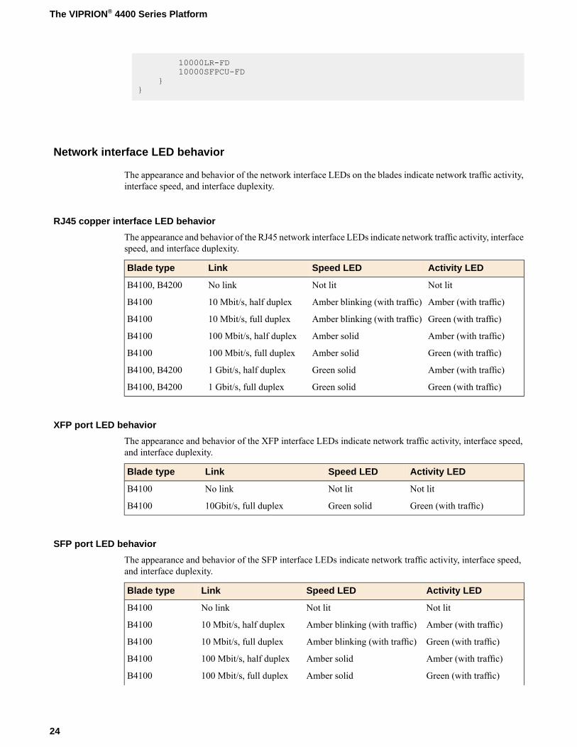
Network interface LED behavior
The appearance and behavior of the network interface LEDs on the blades indicate network traffic activity,interface speed, and interface duplexity.
RJ45 copper interface LED behavior
The appearance and behavior of the RJ45 network interface LEDs indicate network traffic activity, interfacespeed, and interface duplexity.
Activity LEDSpeed LEDLinkBlade type
Not litNot litNo linkB4100, B4200
Amber (with traffic)Amber blinking (with traffic)10 Mbit/s, half duplexB4100
Green (with traffic)Amber blinking (with traffic)10 Mbit/s, full duplexB4100
Amber (with traffic)Amber solid100 Mbit/s, half duplexB4100
Green (with traffic)Amber solid100 Mbit/s, full duplexB4100
Amber (with traffic)Green solid1 Gbit/s, half duplexB4100, B4200
Green (with traffic)Green solid1 Gbit/s, full duplexB4100, B4200
XFP port LED behavior
The appearance and behavior of the XFP interface LEDs indicate network traffic activity, interface speed,and interface duplexity.
Activity LEDSpeed LEDLinkBlade type
Not litNot litNo linkB4100
Green (with traffic)Green solid10Gbit/s, full duplexB4100
SFP port LED behavior
The appearance and behavior of the SFP interface LEDs indicate network traffic activity, interface speed,and interface duplexity.
Activity LEDSpeed LEDLinkBlade type
Not litNot litNo linkB4100
Amber (with traffic)Amber blinking (with traffic)10 Mbit/s, half duplexB4100
Green (with traffic)Amber blinking (with traffic)10 Mbit/s, full duplexB4100
Amber (with traffic)Amber solid100 Mbit/s, half duplexB4100
Green (with traffic)Amber solid100 Mbit/s, full duplexB4100
24
The VIPRION® 4400 Series Platform
Activity LEDSpeed LEDLinkBlade type
Amber (with traffic)Green solid1 Gbit/s, half duplexB4100
Green (with traffic)Green solid1 Gbit/s, full duplexB4100
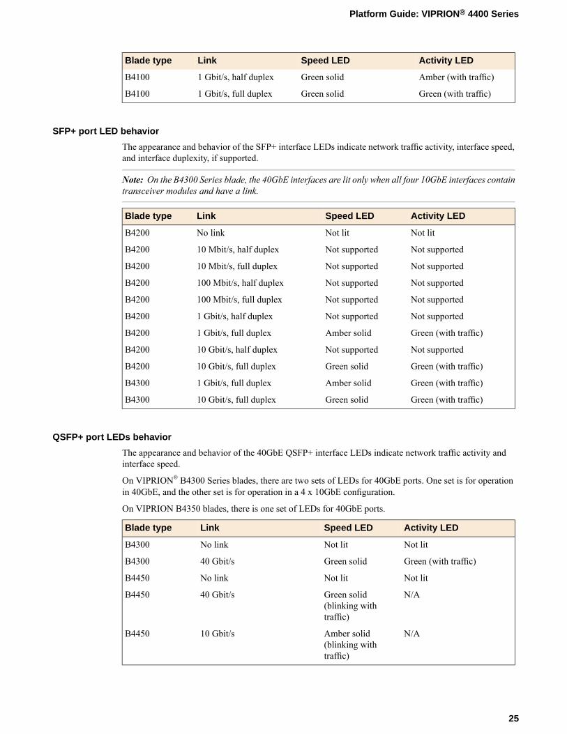
SFP+ port LED behavior
The appearance and behavior of the SFP+ interface LEDs indicate network traffic activity, interface speed,and interface duplexity, if supported.
Note: On the B4300 Series blade, the 40GbE interfaces are lit only when all four 10GbE interfaces containtransceiver modules and have a link.
Activity LEDSpeed LEDLinkBlade type
Not litNot litNo linkB4200
Not supportedNot supported10 Mbit/s, half duplexB4200
Not supportedNot supported10 Mbit/s, full duplexB4200
Not supportedNot supported100 Mbit/s, half duplexB4200
Not supportedNot supported100 Mbit/s, full duplexB4200
Not supportedNot supported1 Gbit/s, half duplexB4200
Green (with traffic)Amber solid1 Gbit/s, full duplexB4200
Not supportedNot supported10 Gbit/s, half duplexB4200
Green (with traffic)Green solid10 Gbit/s, full duplexB4200
Green (with traffic)Amber solid1 Gbit/s, full duplexB4300
Green (with traffic)Green solid10 Gbit/s, full duplexB4300
QSFP+ port LEDs behavior
The appearance and behavior of the 40GbE QSFP+ interface LEDs indicate network traffic activity andinterface speed.
On VIPRION® B4300 Series blades, there are two sets of LEDs for 40GbE ports. One set is for operationin 40GbE, and the other set is for operation in a 4 x 10GbE configuration.
On VIPRION B4350 blades, there is one set of LEDs for 40GbE ports.
Activity LEDSpeed LEDLinkBlade type
Not litNot litNo linkB4300
Green (with traffic)Green solid40 Gbit/sB4300
Not litNot litNo linkB4450
N/AGreen solid(blinking withtraffic)
40 Gbit/sB4450
N/AAmber solid(blinking withtraffic)
10 Gbit/sB4450
25
Platform Guide: VIPRION® 4400 Series

QSFP28 port LEDs behavior
The appearance and behavior of the 100GbE QSFP28 port LEDs indicate network traffic activity andinterface speed.
On VIPRION® B4350 blades, there is one set of LEDs for QSFP28 ports.
SpeedLinkBlade type
Not litNo linkB4450
Solid blue (blinking with traffic)100 Gbit/sB4450
Transceiver module specifications
For current specification information for optical transceivers that are supported by this platform, see F5®
Platforms: Accessories.
Cable pinout specifications
For current pinout information for this platform, see F5® Platforms: Accessories.
26
The VIPRION® 4400 Series Platform
Platform Installation
About installing the platform
After you have reviewed the hardware requirements and become familiar with the VIPRION® 4400 Seriesplatform, you can install the chassis.
Warning: Due to the weight of the platform, at least two people are required to install this chassis into arack. Failing to use two people can result in severe personal injury or equipment damage.
Important: Before you install this platform, review the environmental guidelines to make sure that you areinstalling and using the platform into a compatible rack and in the appropriate environment.
Important: F5® strongly recommends that you install the chassis into a rack before you install any blades.This ensures that the weight of the chassis remains manageable as you install the chassis into a rack.
Note: After you install a blade, wait approximately one to two minutes before installing another to ensurethat each blade has sufficient time to boot. When the Status LED is green, the blade is fully booted.
About general recommendations for rack mounting
Although not required, a 1U empty space between chassis makes it easier for you to remove the chassisfrom the rack in the event that the chassis requires service. A 1U space between chassis also providesadditional cable routing options.
Leaving at least 100 mm of space from the front panel of the chassis to the rack front or rack door providesenough room for you to route the cables without excessive bending or insulation damage.
A shelf or similar device is required to support the chassis if only one person is installing the chassis.
Warning: Due to the weight of the platform, at least two people are required to install this chassis into arack. Failing to use two people can result in severe personal injury or equipment damage.
Important: This product is sensitive to electrostatic discharge (ESD). F5® recommends that you use properESD grounding procedures and equipment when you install or maintain the unit.
Hardware included with the VIPRION 4400 Series AC chassis
The VIPRION 4400 Series AC-powered chassis should include all of the hardware components listed here.
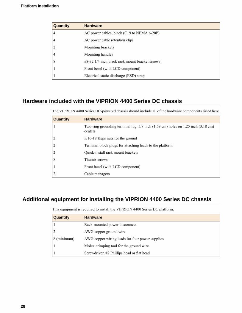
HardwareQuantity
AC power cables, black (C19 to NEMA 6-20P)4
AC power cable retention clips4
Mounting brackets2
Mounting handles4
#8-32 1/4 inch black rack mount bracket screws8
Front bezel (with LCD component)1
Electrical static discharge (ESD) strap1
Hardware included with the VIPRION 4400 Series DC chassis
The VIPRION 4400 Series DC-powered chassis should include all of the hardware components listed here.
HardwareQuantity
Two-ring grounding terminal lug, 5/8 inch (1.59 cm) holes on 1.25 inch (3.18 cm)centers
1
5/16-18 Keps nuts for the ground2
Terminal block plugs for attaching leads to the platform2
Quick-install rack mount brackets2
Thumb screws8
Front bezel (with LCD component)1
Cable managers2
Additional equipment for installing the VIPRION 4400 Series DC chassis
This equipment is required to install the VIPRION 4400 Series DC platform.
HardwareQuantity
Rack-mounted power disconnect1
AWG copper ground wire2
AWG copper wiring leads for four power supplies8 (minimum)
Molex crimping tool for the ground wire1
Screwdriver, #2 Phillips head or flat head1
28
Platform Installation
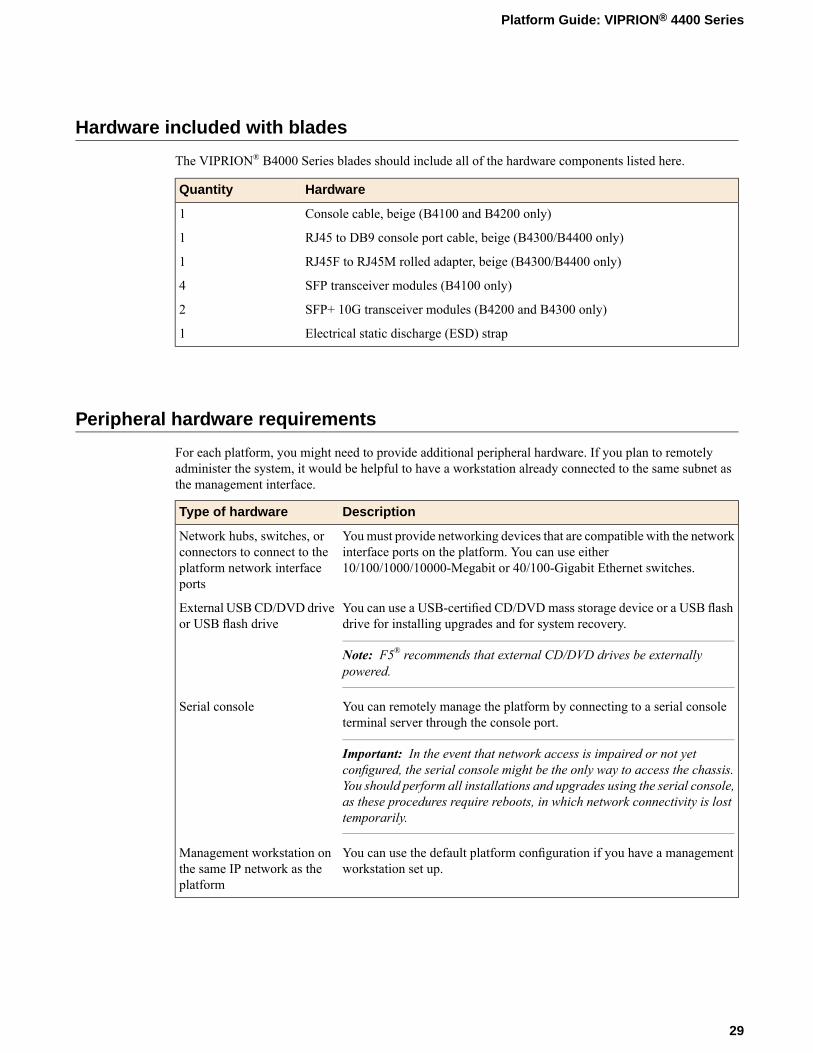
Hardware included with blades
The VIPRION® B4000 Series blades should include all of the hardware components listed here.
HardwareQuantity
Console cable, beige (B4100 and B4200 only)1
RJ45 to DB9 console port cable, beige (B4300/B4400 only)1
RJ45F to RJ45M rolled adapter, beige (B4300/B4400 only)1
SFP transceiver modules (B4100 only)4
SFP+ 10G transceiver modules (B4200 and B4300 only)2
Electrical static discharge (ESD) strap1
Peripheral hardware requirements
For each platform, you might need to provide additional peripheral hardware. If you plan to remotelyadminister the system, it would be helpful to have a workstation already connected to the same subnet asthe management interface.
DescriptionType of hardware
Youmust provide networking devices that are compatible with the networkinterface ports on the platform. You can use either10/100/1000/10000-Megabit or 40/100-Gigabit Ethernet switches.
Network hubs, switches, orconnectors to connect to theplatform network interfaceports
You can use a USB-certified CD/DVDmass storage device or a USB flashdrive for installing upgrades and for system recovery.
Note: F5® recommends that external CD/DVD drives be externallypowered.
External USBCD/DVD driveor USB flash drive
You can remotely manage the platform by connecting to a serial consoleterminal server through the console port.
Important: In the event that network access is impaired or not yetconfigured, the serial console might be the only way to access the chassis.
Serial console
You should perform all installations and upgrades using the serial console,as these procedures require reboots, in which network connectivity is losttemporarily.
You can use the default platform configuration if you have a managementworkstation set up.
Management workstation onthe same IP network as theplatform
29
Platform Guide: VIPRION® 4400 Series
Unpacking the chassis
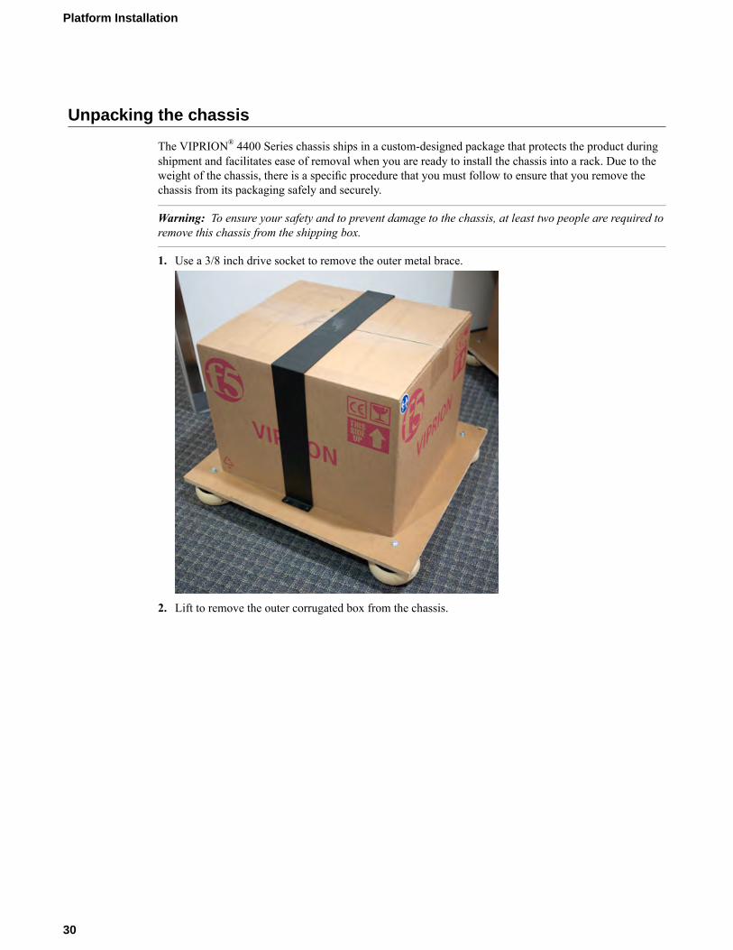
The VIPRION® 4400 Series chassis ships in a custom-designed package that protects the product duringshipment and facilitates ease of removal when you are ready to install the chassis into a rack. Due to theweight of the chassis, there is a specific procedure that you must follow to ensure that you remove thechassis from its packaging safely and securely.
Warning: To ensure your safety and to prevent damage to the chassis, at least two people are required toremove this chassis from the shipping box.
1. Use a 3/8 inch drive socket to remove the outer metal brace.
2. Lift to remove the outer corrugated box from the chassis.
30
Platform Installation
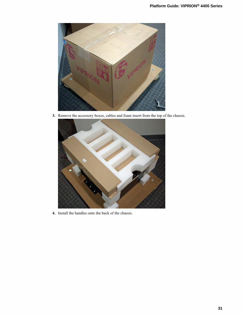
3. Remove the accessory boxes, cables and foam insert from the top of the chassis.
4. Install the handles onto the back of the chassis.
31
Platform Guide: VIPRION® 4400 Series
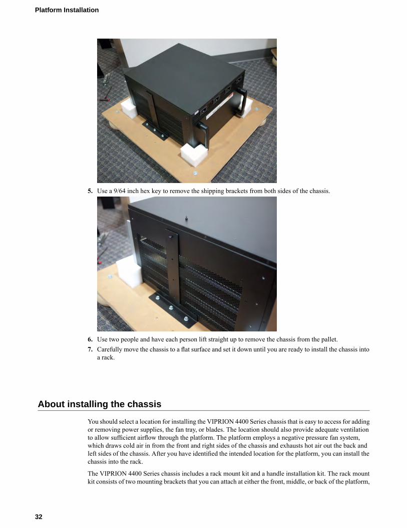
5. Use a 9/64 inch hex key to remove the shipping brackets from both sides of the chassis.
6. Use two people and have each person lift straight up to remove the chassis from the pallet.7. Carefully move the chassis to a flat surface and set it down until you are ready to install the chassis into
a rack.
About installing the chassis
You should select a location for installing the VIPRION 4400 Series chassis that is easy to access for addingor removing power supplies, the fan tray, or blades. The location should also provide adequate ventilationto allow sufficient airflow through the platform. The platform employs a negative pressure fan system,which draws cold air in from the front and right sides of the chassis and exhausts hot air out the back andleft sides of the chassis. After you have identified the intended location for the platform, you can install thechassis into the rack.
The VIPRION 4400 Series chassis includes a rack mount kit and a handle installation kit. The rack mountkit consists of two mounting brackets that you can attach at either the front, middle, or back of the platform,
32
Platform Installation
using the screws provided with the chassis. The location at which you attach the brackets depends on theconfiguration of the rack. The handle installation kit includes four handles and eight screws for attachingthe handles to the chassis. The handles make it easier to lift the chassis into position for rack mounting. Youmust install the rack mount brackets before you can install the handle kit to lift the chassis into position.
The chassis is designed for 19-inch racks. If you are installing into a wider rack, you will need to provideadapters. The four-point rack mounting rail kit will not work with 23-inch racks.
Caution: If you have not yet removed the chassis from the shipping pallet, F5®Networks highly recommendsthat you have at least two people remove the chassis from the pallet. This ensures your safety and preventsdamage to the chassis.
Important: Before you install this platform, review the environmental guidelines to make sure that you areinstalling and using the platform into a compatible rack and in the appropriate environment.
Important: This product is sensitive to electrostatic discharge (ESD). F5® recommends that you use properESD grounding procedures and equipment when you install or maintain the unit.
Installing the rack mount brackets
Before you install this platform, review the environmental guidelines to make sure that you are installingand using the platform in the appropriate environment.
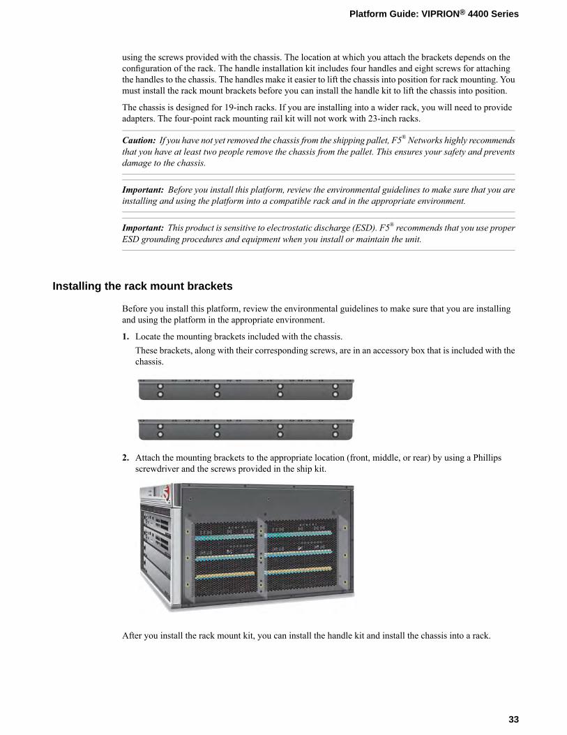
1. Locate the mounting brackets included with the chassis.These brackets, along with their corresponding screws, are in an accessory box that is included with thechassis.
2. Attach the mounting brackets to the appropriate location (front, middle, or rear) by using a Phillipsscrewdriver and the screws provided in the ship kit.
After you install the rack mount kit, you can install the handle kit and install the chassis into a rack.
33
Platform Guide: VIPRION® 4400 Series
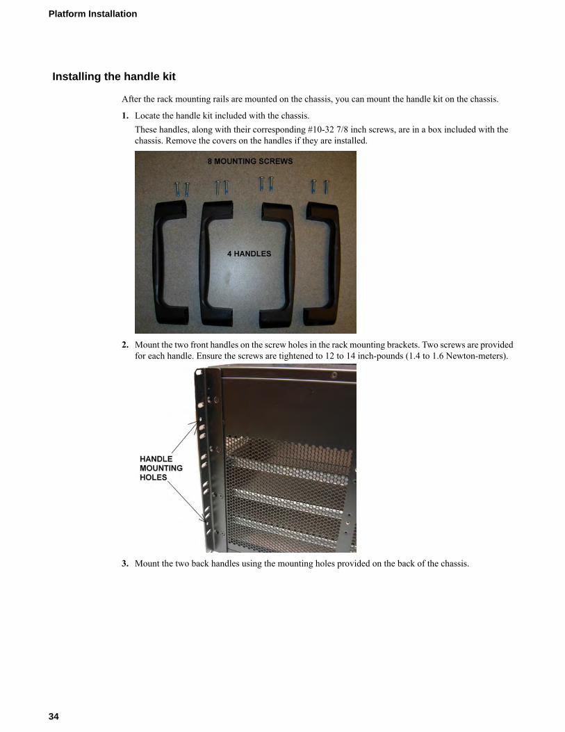
Installing the handle kit
After the rack mounting rails are mounted on the chassis, you can mount the handle kit on the chassis.
1. Locate the handle kit included with the chassis.These handles, along with their corresponding #10-32 7/8 inch screws, are in a box included with thechassis. Remove the covers on the handles if they are installed.
2. Mount the two front handles on the screw holes in the rack mounting brackets. Two screws are providedfor each handle. Ensure the screws are tightened to 12 to 14 inch-pounds (1.4 to 1.6 Newton-meters).
3. Mount the two back handles using the mounting holes provided on the back of the chassis.
34
Platform Installation
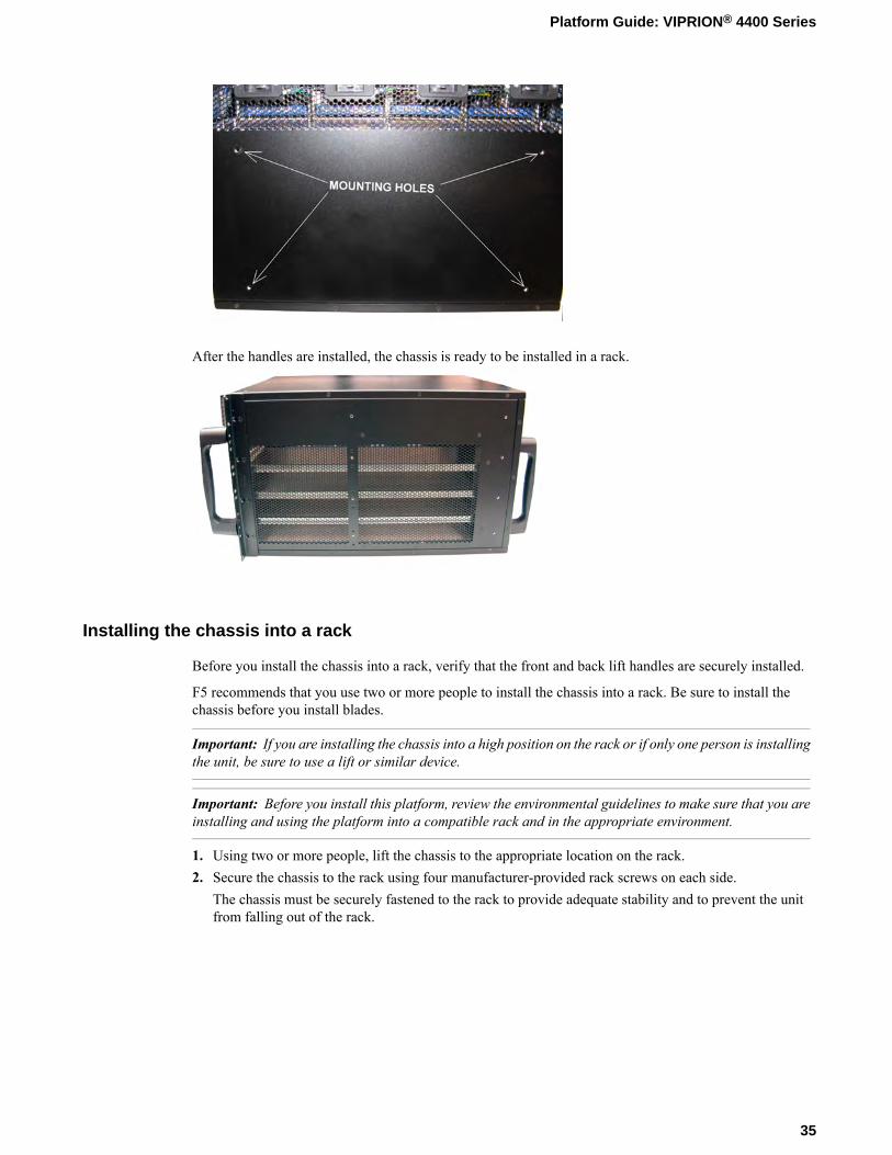
After the handles are installed, the chassis is ready to be installed in a rack.
Installing the chassis into a rack
Before you install the chassis into a rack, verify that the front and back lift handles are securely installed.
F5 recommends that you use two or more people to install the chassis into a rack. Be sure to install thechassis before you install blades.
Important: If you are installing the chassis into a high position on the rack or if only one person is installingthe unit, be sure to use a lift or similar device.
Important: Before you install this platform, review the environmental guidelines to make sure that you areinstalling and using the platform into a compatible rack and in the appropriate environment.
1. Using two or more people, lift the chassis to the appropriate location on the rack.2. Secure the chassis to the rack using four manufacturer-provided rack screws on each side.
The chassis must be securely fastened to the rack to provide adequate stability and to prevent the unitfrom falling out of the rack.
35
Platform Guide: VIPRION® 4400 Series
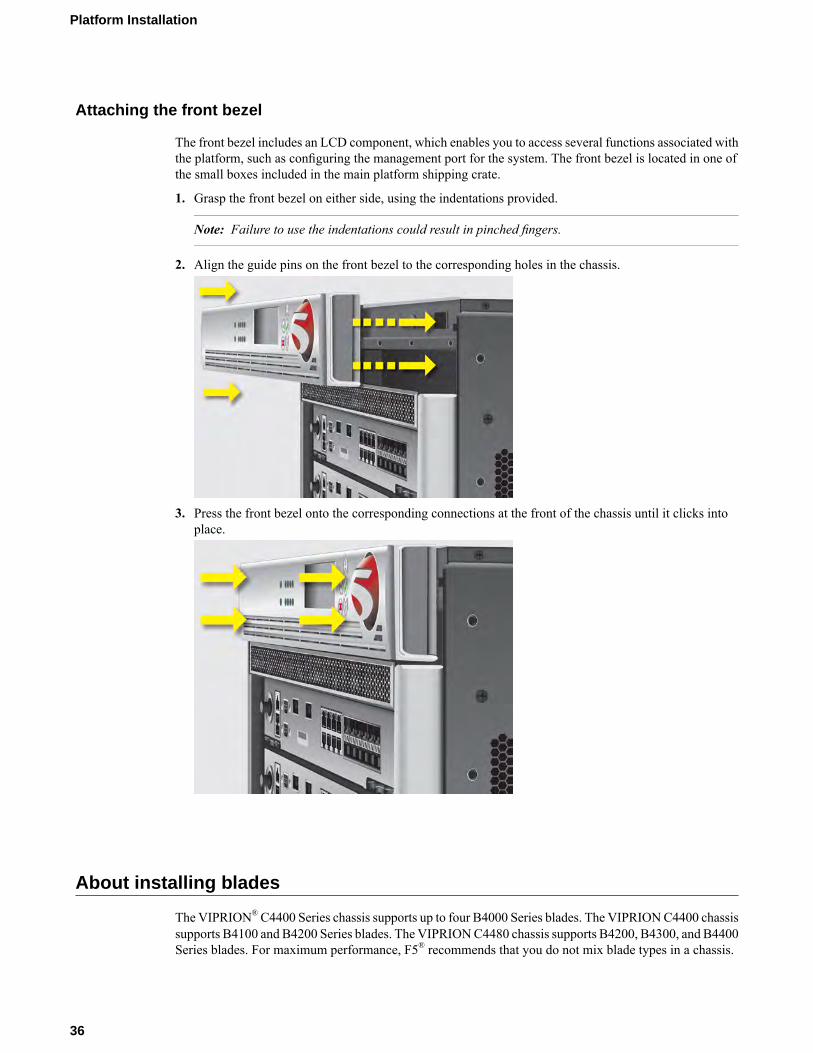
Attaching the front bezel
The front bezel includes an LCD component, which enables you to access several functions associated withthe platform, such as configuring the management port for the system. The front bezel is located in one ofthe small boxes included in the main platform shipping crate.
1. Grasp the front bezel on either side, using the indentations provided.
Note: Failure to use the indentations could result in pinched fingers.
2. Align the guide pins on the front bezel to the corresponding holes in the chassis.
3. Press the front bezel onto the corresponding connections at the front of the chassis until it clicks intoplace.
About installing blades
The VIPRION®C4400 Series chassis supports up to four B4000 Series blades. The VIPRIONC4400 chassissupports B4100 and B4200 Series blades. The VIPRIONC4480 chassis supports B4200, B4300, and B4400Series blades. For maximum performance, F5® recommends that you do not mix blade types in a chassis.
36
Platform Installation
When you initially receive the chassis, the slots that can contain these blades are filled with blanks. A blankmust be installed in each empty slot to ensure proper thermal management and regulatory compliance. Toadd a new blade, you first remove the blank from the corresponding slot and then insert the blade. Be sureto keep the blanks in case you need to change the blade configuration later. You should not operate thechassis for an extended period of time without all slots populated.
Important: This product is sensitive to electrostatic discharge (ESD). F5® recommends that you use properESD grounding procedures and equipment when you install or maintain the unit.
Note: Ensure that you supply power to the chassis prior to installing any blades.
Note: You should install blades into the chassis starting at the top slot and then in each subsequent emptyslot.
Note: After you install a blade, wait approximately one to two minutes before installing another to ensurethat each blade has sufficient time to boot. When the Status LED is green, the blade is fully booted.
Note: The last blade that you install in a fully-populated chassis typically requires more insertion forcethan the previous blades due to the cumulative compression of the electromagnetic interference (EMI)gaskets.
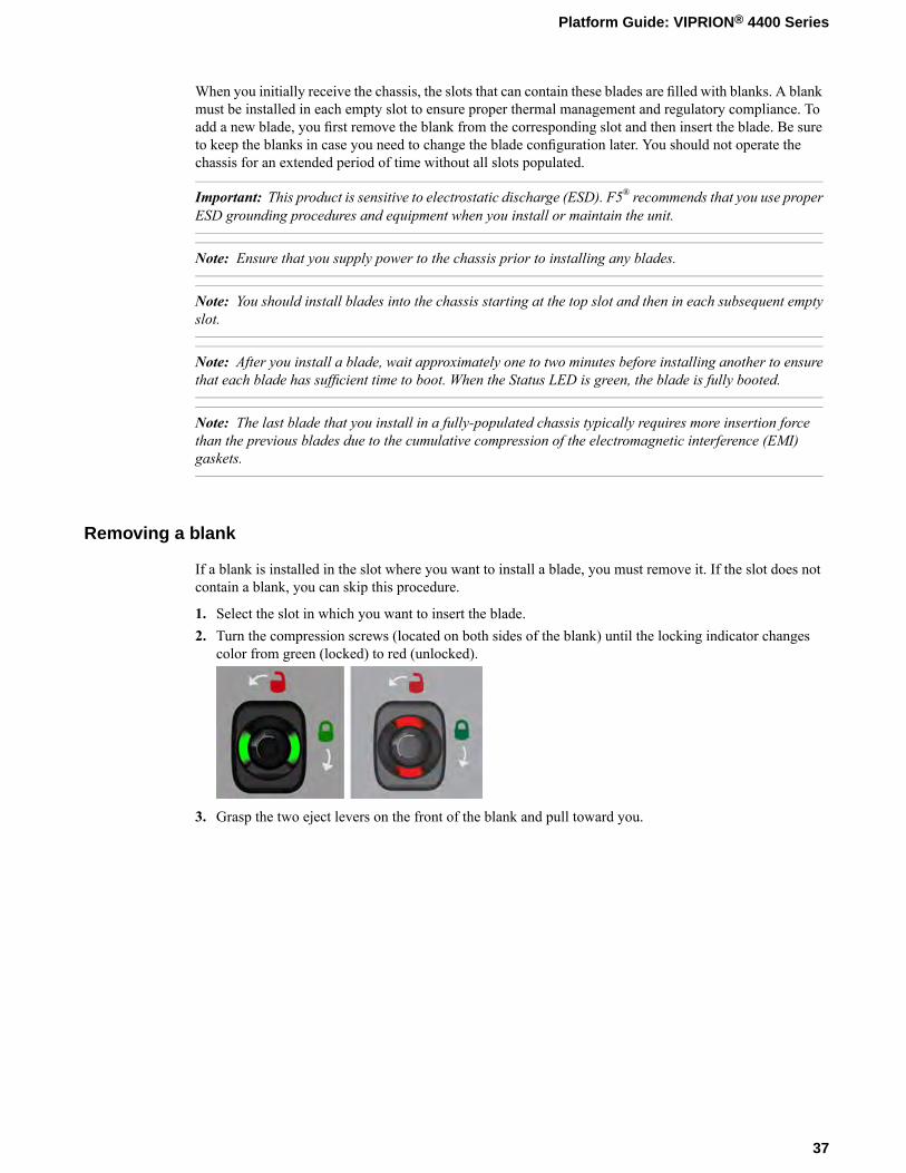
Removing a blank
If a blank is installed in the slot where you want to install a blade, you must remove it. If the slot does notcontain a blank, you can skip this procedure.
1. Select the slot in which you want to insert the blade.2. Turn the compression screws (located on both sides of the blank) until the locking indicator changes
color from green (locked) to red (unlocked).
3. Grasp the two eject levers on the front of the blank and pull toward you.
37
Platform Guide: VIPRION® 4400 Series

4. Fully extend the eject levers on both sides of the blank and pull out toward you to remove the blank.
Removing a blade
1. Identify the blade that you would like to remove from the chassis.2. Halt the blade:
a) Connect to the blade using the serial console.b) Halt the blade.
halt
The blade is halted when the system displays: halted.
3. Disconnect all cables and remove any optical modules.4. Turn the compression screws, located on both sides of the blade, until the locking indicator changes
color from green (locked) to red (unlocked).
38
Platform Installation
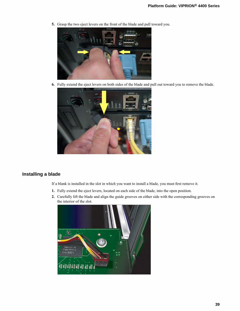
5. Grasp the two eject levers on the front of the blade and pull toward you.
6. Fully extend the eject levers on both sides of the blade and pull out toward you to remove the blade.
Installing a blade
If a blank is installed in the slot in which you want to install a blade, you must first remove it.
1. Fully extend the eject levers, located on each side of the blade, into the open position.2. Carefully lift the blade and align the guide grooves on either side with the corresponding grooves on
the interior of the slot.
39
Platform Guide: VIPRION® 4400 Series
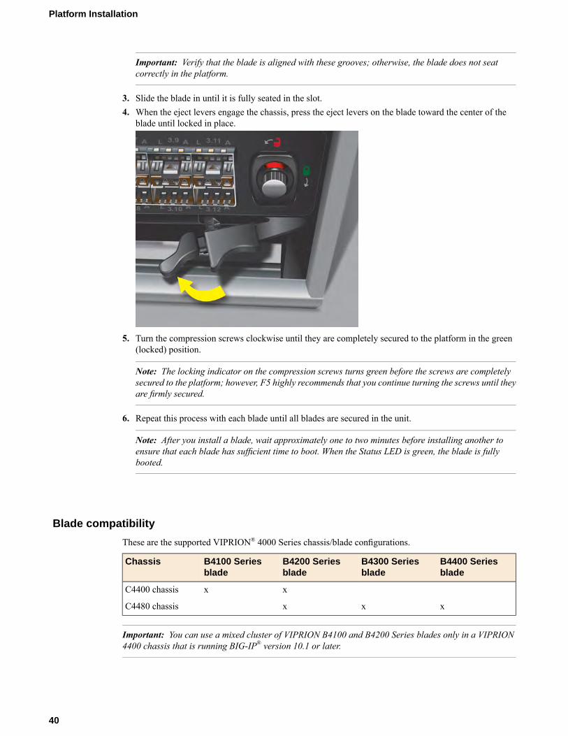
Important: Verify that the blade is aligned with these grooves; otherwise, the blade does not seatcorrectly in the platform.
3. Slide the blade in until it is fully seated in the slot.4. When the eject levers engage the chassis, press the eject levers on the blade toward the center of the
blade until locked in place.
5. Turn the compression screws clockwise until they are completely secured to the platform in the green(locked) position.
Note: The locking indicator on the compression screws turns green before the screws are completelysecured to the platform; however, F5 highly recommends that you continue turning the screws until theyare firmly secured.
6. Repeat this process with each blade until all blades are secured in the unit.
Note: After you install a blade, wait approximately one to two minutes before installing another toensure that each blade has sufficient time to boot. When the Status LED is green, the blade is fullybooted.
Blade compatibility
These are the supported VIPRION® 4000 Series chassis/blade configurations.
B4400 Seriesblade
B4300 Seriesblade
B4200 Seriesblade
B4100 Seriesblade
Chassis
xxC4400 chassis
xxxC4480 chassis
Important: You can use a mixed cluster of VIPRION B4100 and B4200 Series blades only in a VIPRION4400 chassis that is running BIG-IP® version 10.1 or later.
40
Platform Installation

Important: For maximum performance, F5® recommends that you use only blades of the same model,either B4300 or B4400 Series, in a VIPRION 4480 chassis.
Note: You should not mix B4300 or B4400 blades with other blade types in a chassis.
Blade performance in mixed clusters
If you choose to create a mixed cluster, a system that includes a mixture of VIPRION® blade types, allblades will perform at the same level as the earliest blade model installed in the chassis.
For example, if you have three B4200 Series blades and one B4100 Series blade installed in a chassis, theB4200 Series blades will perform at the same level as the B4100 Series blade. Removing all B4100 bladesfrom a mixed cluster, leaving only B4200 Series blades, enables the B4200 Series blades to perform at theirmaximum capacity.
Important: The VIPRION B4300 and B4400 Series blades do not support mixed cluster operation.
Blade software versions in mixed clusters
The behavior of a mixed cluster differs depending on the software versions installed on the blades.B4200 Series blades in a cluster running BIG-IP version 10.0.x and earlier
If you install a B4200 Series blade into a B4100 cluster running a version of the BIG-IP software that isearlier than version 10.1, you could experience these scenarios:
• You receive an error message in the cluster status for the slot in which the B4200 Series blade is installed,indicating that the blade is running the wrong software version. The software installation status alsodisplays an error for the B4200 Series blade slot.
• Earlier BIG-IP software versions might display in the Configuration utility, but you will not be able toinstall them to the B4200 Series blade. You receive an installation error message if you attempt to installan earlier version of the BIG-IP software.
• If you upgrade the cluster to version 10.1 or later, the B4200 Series blade joins the cluster as an activemember.
• If the B4100 Series blades are subsequently removed from the cluster, the situation does not correctitself automatically, as the system will remember that the version of software for that cluster is a versionprior to version 10.1. You can correct this issue by specifying that version 10.1 or later run on the cluster.
• If you move a B4200 Series blade to a second chassis, this does not cause the other chassis to downgradeto a version earlier than version 10.1. Cluster configuration information, which includes the softwareversion information, is tied to the chassis identifier on the chassis hardware and is removed from theblade when it is moved to another chassis.
B4100 Series blades in a cluster running BIG-IP version 10.1 and later
If you install a B4100 Series blade into a chassis with B4200 Series blades running version 10.1 or later,you could experience these scenarios:
• The B4100 Series blade upgrades to the new software and runs (this is the typical, expected behavior).• The software images previously installed on the B4100 Series blade display as installable in the
Configuration utility. If you attempt to install one of those images, you receive an error on the B4200Series blades, but the installation completes successfully on the B4100 Series blades.
41
Platform Guide: VIPRION® 4400 Series
Trunk configuration in mixed clusters
If you replace a B4100 Series blade with a B4200 Series blade in a cluster that uses one or more trunksacross the blades, you must adjust the trunk configuration to match the desired B4200 external interfaces.For example, if your trunk uses 10G ports, interface 1.1 on a B4100 Series blade is 10G, and interface 2.1on a B4200 Series blade is 10G.
For information about configuring your VIPRION system and creating BIG-IP system objects (for example,trunks, VLANS, and self IP addresses), see VIPRION® Systems: Configuration.
Redundant system configuration and mixed clusters
If you have configured device service clustering (DSC™), previously known as a redundant systemconfiguration, and would like to use a mixture of B4100 and B4200 Series blades, you must put the sameblade type in the corresponding slots on each chassis. For example, if you install a B4200 Series blade inslot 1 and a B4100 Series blade in slot 2 on the active chassis, you must install a B4200 in slot 1 and aB4100 Series blade in slot 2 in the standby chassis.
About powering the VIPRION 4400 Series AC platform
The AC platform ships with four power cords that you must use with the installed power supplies to powerthe chassis.
Important: Do not use any power cords other than those specifically designed for the VIPRION 4400 Seriesplatform.
Powering the AC platform
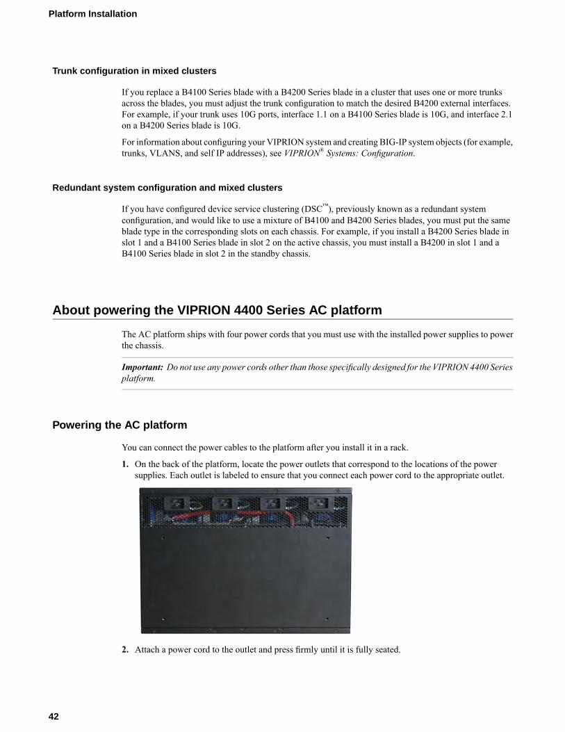
You can connect the power cables to the platform after you install it in a rack.
1. On the back of the platform, locate the power outlets that correspond to the locations of the powersupplies. Each outlet is labeled to ensure that you connect each power cord to the appropriate outlet.
2. Attach a power cord to the outlet and press firmly until it is fully seated.
42
Platform Installation
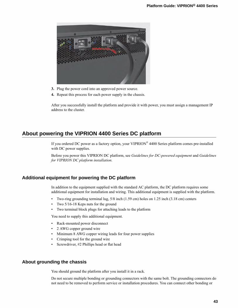
3. Plug the power cord into an approved power source.4. Repeat this process for each power supply in the chassis.
After you successfully install the platform and provide it with power, you must assign a management IPaddress to the cluster.
About powering the VIPRION 4400 Series DC platform
If you ordered DC power as a factory option, your VIPRION® 4400 Series platform comes pre-installedwith DC power supplies.
Before you power this VIPRION DC platform, see Guidelines for DC-powered equipment and Guidelinesfor VIPRION DC platform installation.
Additional equipment for powering the DC platform
In addition to the equipment supplied with the standard AC platform, the DC platform requires someadditional equipment for installation and wiring. This additional equipment is supplied with the platform.
• Two-ring grounding terminal lug, 5/8 inch (1.59 cm) holes on 1.25 inch (3.18 cm) centers• Two 5/16-18 Keps nuts for the ground• Two terminal block plugs for attaching leads to the platform
You need to supply this additional equipment.
• Rack-mounted power disconnect• 2 AWG copper ground wire• Minimum 8 AWG copper wiring leads for four power supplies• Crimping tool for the ground wire• Screwdriver, #2 Phillips head or flat head
About grounding the chassis
You should ground the platform after you install it in a rack.
Do not secure multiple bonding or grounding connectors with the same bolt. The grounding connectors donot need to be removed to perform service or installation procedures. You can connect other bonding or
43
Platform Guide: VIPRION® 4400 Series

grounding conductors to a grounding connector provided a reliable bond between the connector and theequipment is not disturbed during installation, service, or maintenance of the platform.
Important: All copper grounding cable compression-type terminal lugs used for grounding must meet allappropriate safety standards.
Note: The VIPRION 4400 Series platform must be grounded to a common bonding network (CBN).
Figure 13: Chassis ground lugs
Connecting the ground lug to the ground terminal
After the unit is installed in the rack and before you provide power to the system, you need to connect thegrounding hardware.
1. Use a crimping tool to crimp the ground wire to the two-ring ground terminal lug.Use a 2 AWG copper wire for grounding.
2. Attach the two-ring ground terminal lug to the ground terminal.3. Install the M6 Keps nuts on the ground terminal lugs.
Use 16 to 18 inch-pounds (1.8 to 2.0 Newton-meters) of torque on these Keps nuts.
4. Connect the ground wire to a common bonding network (CBN).
About connecting the DC power source
After the platform is installed in a rack, you can wire the platform to the DC power source. When youconnect the DC power source, you should also follow the safety requirements defined for your networkoperations center (NOC).
There are two groups of terminals on the back of the chassis. When you view the chassis from the rear,there is one on the left side and one on the right side. Each terminal group contains the leads for two powersupplies.
• Use the group of leads on the right rear of the chassis labeled PWR 2 and PWR 1 for power supplies 2and 1.
• Use the group of leads on the left rear of the chassis labeled PWR 4 and PWR 3 for power supplies 4and 3.
44
Platform Installation

Figure 14: DC terminal block plug
Note: The battery return terminals on the DC-powered platform are in an isolated DC return (DC-I)configuration.
Connecting DC power to the platform
After the unit is installed in the rack and before you provide power to the system, you need to connect thegrounding hardware.
1. After you are sure the power is off and the ground lug is connected to the ground terminal, you canconnect the DC power source.
2. After you connect the ground lug, connect the negative DC power lead to the -48V terminal on theterminal block plug.The terminals are clearly labeled. You should strip at least 0.50 in. (12.7 mm) of insulation off of eachwire where you connect the wire to the terminal block plug.
3. Connect the positive DC wire to the RTN terminal on the terminal block plug.You should strip at least 0.50 in. (12.7 mm) of insulation off of each wire where you connect the wireto the terminal block plug.
4. Wire each supply in this manner until you have wired each terminal block plug for the two powersupplies.
5. Plug each terminal block plug into the plug on the back of the chassis.Use the screws supplied to attach each wiring block to the plug in the chassis. Use 16 to 18 inch-pounds(1.8 to 2.0 Newton-meters) of torque on these screws.
6. Power on the DC power source.The system begins to boot.
After you successfully install the platform and provide it with power, you must assign a management IPaddress to the cluster.
Connecting the cables and other hardware
After you have installed the chassis into the rack, connect the cables and other hardware.
45
Platform Guide: VIPRION® 4400 Series
Note: Serial (hard-wired) failover is not currently supported between VIPRION chassis. If you would liketo set up device service clustering (DSC®), previously known as a redundant system configuration, you mustconfigure network failover. For more information, see BIG-IP® Device Service Clustering: Administration.
1. Connect an Ethernet cable to the MGMT port if you are using the default network configured on themanagement interface.
2. Connect the platform to a serial console server.
Important: In the event that network access is impaired or not yet configured, the serial console mightbe the only way to access the chassis. F5® strongly recommends that you perform all installations andupgrades using the serial console, as these procedures require reboots, in which network connectivityis lost temporarily.
• Connect the serial console cable supplied by F5 to the CONSOLE port.
Note: The default serial port settings are 19200, n, 8, 1.
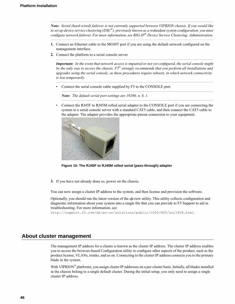
• Connect the RJ45F to RJ45M rolled serial adapter to the CONSOLE port if you are connecting thesystem to a serial console server with a standard CAT5 cable, and then connect the CAT5 cable tothe adapter. The adapter provides the appropriate pinout connection to your equipment.
Figure 15: The RJ45F to RJ45M rolled serial (pass-through) adapter
3. If you have not already done so, power on the chassis.
You can now assign a cluster IP address to the system, and then license and provision the software.
Optionally, you should run the latest version of the qkview utility. This utility collects configuration anddiagnostic information about your system into a single file that you can provide to F5 Support to aid introubleshooting. For more information, seehttp://support.f5.com/kb/en-us/solutions/public/1000/800/sol1858.html.
About cluster management
The management IP address for a cluster is known as the cluster IP address. The cluster IP address enablesyou to access the browser-based Configuration utility to configure other aspects of the product, such as theproduct license, VLANs, trunks, and so on. Connecting to the cluster IP address connects you to the primaryblade in the system.
With VIPRION® platforms, you assign cluster IP addresses on a per-cluster basis. Initially, all blades installedin the chassis belong to a single default cluster. During the initial setup, you only need to assign a singlecluster IP address.
46
Platform Installation
A blade within a cluster is known as a cluster member. You can assign a management IP address to eachcluster member.
Important: When you configure an IP address for a blade, that IP address corresponds to the slot in whichthe blade resides. If you replace that blade with another, the new blade automatically receives thepreviously-configured management IP address, provided that a second operating blade is installed in thesystem. At least one operational blade is required at all time to preserve the existing configuration data.
You can manage clusters using these methods:
• LCD panel• config utility• tmsh commands
Configuring the cluster IP address from the LCD
You can use the LCD panel to configure the cluster IP address. The options for cluster and blade managementare located in the Cluster menu item under the System menu.
Note: When using the LCD to manage clusters, be sure to use the Commit menu option after changing eachsetting. Alternatively, you can change all cluster-related settings and use the Commit option to save allsettings at once.
1. Press the X button to access the LCD panel menus.2. Use the arrow keys to select System and press the Check button.3. Use the arrow keys to select Cluster and press the Check button.4. Use the arrow keys to select Cluster Mgmt and press the Check button.5. Use the arrow keys to select Cluster IP and press the Check button.
The LCD panel shows the current IP address of the cluster. The default value is 192.168.1.246.
6. Use the arrow keys to configure the IP address of the cluster.7. Press the X button until you return to the Cluster Mgmt menu.8. Use the arrow keys to select Commit and press the Check button.
The system saves the new IP address for the cluster. You can now access the browser-based Configurationutility using the cluster IP address you assigned.
Configuring the cluster IP subnet mask from the LCD
You can use the LCD panel to configure the cluster IP subnet mask.
1. Press the X button to access the LCD panel menus.2. Use the arrow keys to select System and press the Check button.3. Use the arrow keys to select Cluster and press the Check button.4. Use the arrow keys to select Cluster Mgmt and press the Check button.5. Use the arrow keys to select Cluster IP Mask and press the Check button.
The LCD shows the current subnet mask address of the cluster. The default value is 255.255.255.0.
6. Use the arrow keys to configure the subnet mask of the cluster.7. Press the X button until you return to the Cluster Mgmt menu.8. Use the arrow keys to select Commit and press the Check button.
47
Platform Guide: VIPRION® 4400 Series
The system saves the new subnet mask for the cluster.
Configuring the default gateway IP address for the cluster from the LCD
You can use the LCD panel to configure the default gateway IP address for the cluster.
1. Press the X button to access the LCD panel menus.2. Use the arrow keys to select System and press the Check button.3. Use the arrow keys to select Cluster and press the Check button.4. Use the arrow keys to select Cluster Mgmt and press the Check button.5. Use the arrow keys to select Gateway and press the Check button.
The LCD shows the current gateway IP address of the cluster. The default value is 0.0.0.0.
6. Use the arrow keys to configure the gateway IP address of the cluster.7. Press the X button until you return to the Cluster Mgmt menu.8. Use the arrow keys to select Commit and press the Check button.
The system saves the new default gateway IP address for the cluster.
Configuring the management IP address of a cluster member from the LCD
You can use the LCD panel to configure the management IP address of a cluster member.
1. Press the X button to access the LCD panel menus.2. Use the arrow keys to select System and press the Check button.3. Use the arrow keys to select Cluster and press the Check button.4. Use the arrow keys to select Cluster Mbrs and press the Check button.5. Use the arrow keys to select the appropriate blade () and press the Check button.6. Use the arrow keys to select Blade Mgmt IP and press the Check button.
The LCD shows the current IP address of the blade. The default value is 0.0.0.0.
7. Use the arrow keys to configure the IP address of the blade.8. Press the X button until you return to the Blade [1-] Mgmt menu.9. Use the arrow keys to select Commit and press the Check button.
The system saves the new IP address for the blade.
Configuring the cluster IP address using the config utility
You can configure the cluster IP address using the config utility after you connect a blade to a serialconsole.
1. Connect to the system using the serial console.2. Start the config utility.
config
The config utility displays.3. Follow the prompts to configure the cluster IP address, subnet mask, and gateway address for the
management port.
48
Platform Installation
The system saves the new IP address, subnet mask, and gateway address for the cluster. You can now accessthe browser-based Configuration utility using the cluster IP address you assigned.
Configuring the cluster IP address using tmsh
You can configure the cluster IP address using tmsh after you connect a blade to a serial console.
1. Connect to the system using the serial console.2. Set the cluster IP address and subnet mask.
tmsh modify sys cluster default address <ip_address/mask>Example: tmsh modify sys cluster default address 192.168.217.44/24
3. Set the default gateway for the cluster.tmsh modify sys management-route default gateway <gateway_ip>Example: tmsh modify sys management-route default gateway 172.20.80.254
4. Write the running configuration to the stored configuration files.tmsh sys save [base-config | config]
The system saves the new IP address, subnet mask, and gateway address for the cluster. You can now accessthe browser-based Configuration utility using the cluster IP address you assigned.
Licensing the platform
Once the cluster IP address is configured for the platform, you can use the browser-based Configurationutility to license the appropriate BIG-IP software.
1. Using a Web browser, navigate to the cluster IP address that you assigned to the VIPRION system.Use this format, where <cluster_ip_address> is the cluster IP address you assigned:https://<cluster_ip_address>
2. Type admin as the user name and admin as the password.If this is the first time you have accessed the Configuration utility, the first screen you see is the Licensescreen.
3. Follow the instructions in the Configuration utility to license the platform.For more information about licensing the system, click the Help tab.
Verifying blade availability
At this point, you have installed the VIPRION platform, powered it, installed blades, assigned a cluster IPaddress to the system, and licensed it for use. Next, you need to ensure that the blades are recognized bythe software and available for processing network traffic.
1. Using aWeb browser, navigate to the cluster IP address that you have assigned to the VIPRION platform.The Configuration utility opens.
2. On the Main tab, click System > Clusters.The Clusters screen opens.
49
Platform Guide: VIPRION® 4400 Series

3. In the Cluster Members area, verify that all blades listed have a green status icon in the Status column.The green circle icon indicates that the cluster member is available.
Now you have installed a VIPRION platform successfully and prepared it for use on your network. Thenext steps involve further configuration of the platform by adding the trunks, VLANs, and self IP addressesthat are necessary for the system to manage your network traffic effectively.
50
Platform Installation
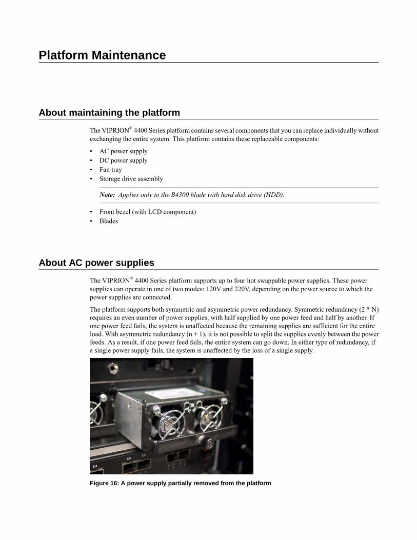
Platform Maintenance
About maintaining the platform
The VIPRION® 4400 Series platform contains several components that you can replace individually withoutexchanging the entire system. This platform contains these replaceable components:
• AC power supply• DC power supply• Fan tray• Storage drive assembly
Note: Applies only to the B4300 blade with hard disk drive (HDD).
• Front bezel (with LCD component)• Blades
About AC power supplies
The VIPRION® 4400 Series platform supports up to four hot swappable power supplies. These powersupplies can operate in one of two modes: 120V and 220V, depending on the power source to which thepower supplies are connected.
The platform supports both symmetric and asymmetric power redundancy. Symmetric redundancy (2 * N)requires an even number of power supplies, with half supplied by one power feed and half by another. Ifone power feed fails, the system is unaffected because the remaining supplies are sufficient for the entireload. With asymmetric redundancy (n + 1), it is not possible to split the supplies evenly between the powerfeeds. As a result, if one power feed fails, the entire system can go down. In either type of redundancy, ifa single power supply fails, the system is unaffected by the loss of a single supply.
Figure 16: A power supply partially removed from the platform

Caution: Running without all power supplies installed in the platform can affect cooling and electromagneticinterference (EMI). If a power supply fails, you can leave it installed in the chassis and remove the powercord; the system, however, will continue to log errors. If you need to run the unit without all power suppliesinstalled, you must install a blank supply bracket into any empty power supply slots. The blank supplybracket is required to maintain proper airflow in the system.
Caution: The power socket outlet should be installed near the equipment and easily accessible.
Important: This product is sensitive to electrostatic discharge (ESD). F5® recommends that you use properESD grounding procedures and equipment when you install or maintain the unit.
Note: Depending on the model and revision type of the power supply, you might need either a Phillips ora slotted screwdriver to replace the power supply.
Installing an AC power supply
If a power supply is already installed in the bay where you are installing the replacement supply, disconnectthe AC power cord for the corresponding power supply from the back of the chassis and remove the existingsupply from the chassis.
In the event of a power supply failure, you can replace an AC power supply without powering down thesystem, provided that there are still enough power supplies to equal one less than the number of runningblades. For example, if the chassis has three blades, you can replace a power supply, as long as the platformhas at least two power supplies operating during the replacement process.
1. Using the indentations on either side of the LCD component, remove the front bezel from the chassis.With the front bezel removed, you can see the power supplies and the available power supply bays.
2. Remove the existing supply, if one is installed.3. Slide the new power supply into the empty power supply bay.4. Lower the power supply eject lever to fully seat the power supply in its bay.5. Secure the power supply in its bay by tightening the screw in the middle of the power supply eject lever.
Note: The screw that holds the ejector handle in place is captive and cannot be removed from theassembly.
6. Attach the power cord for the new power supply to the back of the unit, using the corresponding powersupply connector.
7. Replace the front bezel.
About DC power supplies
The VIPRION® 4400 Series platform supports up to four hot swappable DC power supplies.
You can install a DC power supply without powering down the system, provided that there are still enoughpower supplies to equal one less than the number of running blades. For example, if the chassis has threeblades, you can replace a power supply, as long as the platform has at least two power supplies operatingduring the replacement process.
52
Platform Maintenance
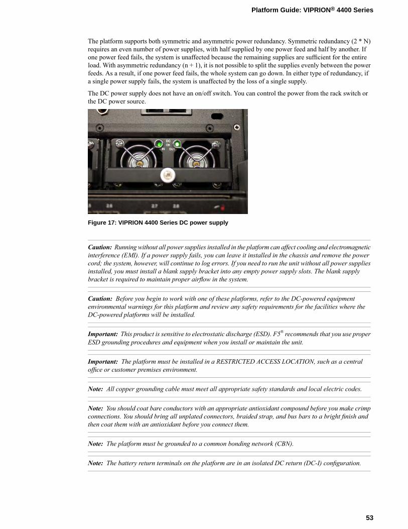
The platform supports both symmetric and asymmetric power redundancy. Symmetric redundancy (2 * N)requires an even number of power supplies, with half supplied by one power feed and half by another. Ifone power feed fails, the system is unaffected because the remaining supplies are sufficient for the entireload. With asymmetric redundancy (n + 1), it is not possible to split the supplies evenly between the powerfeeds. As a result, if one power feed fails, the whole system can go down. In either type of redundancy, ifa single power supply fails, the system is unaffected by the loss of a single supply.
The DC power supply does not have an on/off switch. You can control the power from the rack switch orthe DC power source.
Figure 17: VIPRION 4400 Series DC power supply
Caution: Running without all power supplies installed in the platform can affect cooling and electromagneticinterference (EMI). If a power supply fails, you can leave it installed in the chassis and remove the powercord; the system, however, will continue to log errors. If you need to run the unit without all power suppliesinstalled, you must install a blank supply bracket into any empty power supply slots. The blank supplybracket is required to maintain proper airflow in the system.
Caution: Before you begin to work with one of these platforms, refer to the DC-powered equipmentenvironmental warnings for this platform and review any safety requirements for the facilities where theDC-powered platforms will be installed.
Important: This product is sensitive to electrostatic discharge (ESD). F5® recommends that you use properESD grounding procedures and equipment when you install or maintain the unit.
Important: The platform must be installed in a RESTRICTED ACCESS LOCATION, such as a centraloffice or customer premises environment.
Note: All copper grounding cable must meet all appropriate safety standards and local electric codes.
Note: You should coat bare conductors with an appropriate antioxidant compound before you make crimpconnections. You should bring all unplated connectors, braided strap, and bus bars to a bright finish andthen coat them with an antioxidant before you connect them.
Note: The platform must be grounded to a common bonding network (CBN).
Note: The battery return terminals on the platform are in an isolated DC return (DC-I) configuration.
53
Platform Guide: VIPRION® 4400 Series

Installing a DC power supply
If a power supply is already installed in the bay where you are installing the replacement supply, disconnectthe DC terminal block for the corresponding power supply from the back of the chassis and remove theexisting supply from the chassis.
In the event of a power supply failure, you can replace a DC power supply without powering down thesystem, provided that there are still enough power supplies to equal one less than the number of runningblades. For example, if the chassis has three blades, you can replace a power supply, as long as the platformhas at least two power supplies operating during the replacement process.
Note: You should wait at least five seconds before re-inserting a power supply that you have removed.Otherwise, the LEDs for the power supply might remain OFF, and the system will report that power supplyas being in a down state.
1. Using the indentations on either side of the LCD component, remove the front bezel from the chassis.With the front bezel removed, you can see the power supplies and the available power supply bays.
2. Remove the existing supply, if one is installed.3. Slide the new power supply into the empty power supply bay.4. Lower the power supply eject lever to fully seat the power supply in its bay.5. Secure the power supply in its bay by tightening the screw in the middle of the power supply eject lever.
Note: The screw that holds the ejector handle in place is captive and cannot be removed from theassembly.
6. Connect the DC terminal for the new power supply to the back of the unit, using the correspondingpower supply connector.
7. Replace the front bezel.
About the fan tray
TheVIPRION® 4400 Series platform has a removable fan tray that is designed tomaintain airflow throughoutthe chassis. You can change or replace the fan tray as part of the routine maintenance of the unit, or in theevent of a fan failure. The fans in the fan tray run constantly while the unit is on. Over time, the fans canwear out, requiring you to replace the fan tray.
Important: This product is sensitive to electrostatic discharge (ESD). F5® recommends that you use properESD grounding procedures and equipment when you install or maintain the unit.
54
Platform Maintenance
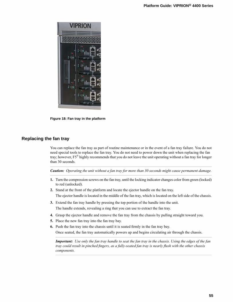
Figure 18: Fan tray in the platform
Replacing the fan tray
You can replace the fan tray as part of routine maintenance or in the event of a fan tray failure. You do notneed special tools to replace the fan tray. You do not need to power down the unit when replacing the fantray; however, F5® highly recommends that you do not leave the unit operating without a fan tray for longerthan 30 seconds.
Caution: Operating the unit without a fan tray for more than 30 seconds might cause permanent damage.
1. Turn the compression screws on the fan tray, until the locking indicator changes color from green (locked)to red (unlocked).
2. Stand at the front of the platform and locate the ejector handle on the fan tray.The ejector handle is located in the middle of the fan tray, which is located on the left side of the chassis.
3. Extend the fan tray handle by pressing the top portion of the handle into the unit.The handle extends, revealing a ring that you can use to extract the fan tray.
4. Grasp the ejector handle and remove the fan tray from the chassis by pulling straight toward you.5. Place the new fan tray into the fan tray bay.6. Push the fan tray into the chassis until it is seated firmly in the fan tray bay.
Once seated, the fan tray automatically powers up and begins circulating air through the chassis.
Important: Use only the fan tray handle to seat the fan tray in the chassis. Using the edges of the fantray could result in pinched fingers, as a fully-seated fan tray is nearly flush with the other chassiscomponents.
55
Platform Guide: VIPRION® 4400 Series
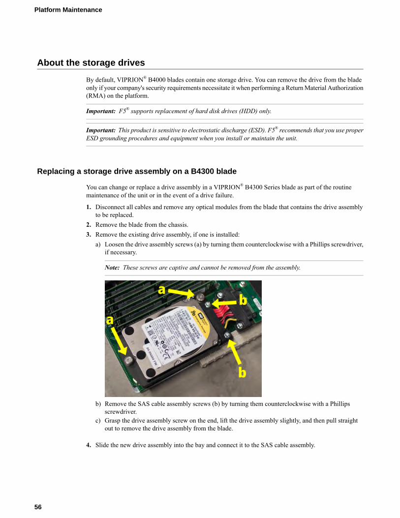
About the storage drives
By default, VIPRION® B4000 blades contain one storage drive. You can remove the drive from the bladeonly if your company's security requirements necessitate it when performing a ReturnMaterial Authorization(RMA) on the platform.
Important: F5® supports replacement of hard disk drives (HDD) only.
Important: This product is sensitive to electrostatic discharge (ESD). F5® recommends that you use properESD grounding procedures and equipment when you install or maintain the unit.
Replacing a storage drive assembly on a B4300 blade
You can change or replace a drive assembly in a VIPRION® B4300 Series blade as part of the routinemaintenance of the unit or in the event of a drive failure.
1. Disconnect all cables and remove any optical modules from the blade that contains the drive assemblyto be replaced.
2. Remove the blade from the chassis.3. Remove the existing drive assembly, if one is installed:
a) Loosen the drive assembly screws (a) by turning them counterclockwise with a Phillips screwdriver,if necessary.
Note: These screws are captive and cannot be removed from the assembly.
b) Remove the SAS cable assembly screws (b) by turning them counterclockwise with a Phillipsscrewdriver.
c) Grasp the drive assembly screw on the end, lift the drive assembly slightly, and then pull straightout to remove the drive assembly from the blade.
4. Slide the new drive assembly into the bay and connect it to the SAS cable assembly.
56
Platform Maintenance
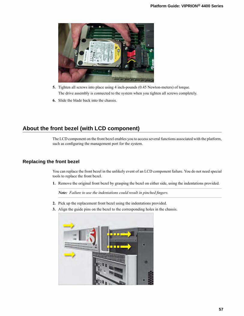
5. Tighten all screws into place using 4 inch-pounds (0.45 Newton-meters) of torque.The drive assembly is connected to the system when you tighten all screws completely.
6. Slide the blade back into the chassis.
About the front bezel (with LCD component)
The LCD component on the front bezel enables you to access several functions associated with the platform,such as configuring the management port for the system.
Replacing the front bezel
You can replace the front bezel in the unlikely event of an LCD component failure. You do not need specialtools to replace the front bezel.
1. Remove the original front bezel by grasping the bezel on either side, using the indentations provided.
Note: Failure to use the indentations could result in pinched fingers.
2. Pick up the replacement front bezel using the indentations provided.3. Align the guide pins on the bezel to the corresponding holes in the chassis.
57
Platform Guide: VIPRION® 4400 Series


Environmental Guidelines
General environmental guidelines
The VIPRION® 4400 Series platform is an industrial network appliance that is designed to be mounted ina standard 19-inch EIA rack. Follow these guidelines to adhere to safety precautions:
• Install the rack according to the manufacturer's instructions and check the rack for stability before placingequipment in it.
• Build and position the rack so that once you install the platform, the power supply and the vents on boththe front and back of the unit remain unobstructed. The platform must have adequate ventilation aroundthe unit at all times.
• Do not allow the air temperature in the room to exceed 104°F (40°C).
Note: NEBS-certified units can withstand air temperatures up to 131°F (55°C). The maximumtemperature is only required to be met for a short period of time.
• Do not plug the unit into a branch circuit shared by more electronic equipment than the circuit is designedto manage safely at one time.
Important: This product is sensitive to electrostatic discharge (ESD). F5® recommends that you use properESD grounding procedures and equipment when you install or maintain the unit.
Caution: Customers should not attempt to replace batteries. There is a risk of explosion if a battery isreplaced with an incorrect type. Field technicians should dispose of used batteries according to theinstructions.
Attention: Il y a risque d'explosion si la batterie est remplacée par une batterie de type incorrect. Mettreau rebut les batteries usagées conformément aux instructions.

Guidelines for the AC-powered platform
An AC-powered installation must meet these requirements:
• Install the unit using a 20 amp external branch circuit protection device.• Normally, one power feed is used for each individual power supply.
Important: The platform must be installed in a RESTRICTED ACCESS LOCATION, such as a centraloffice or customer premises environment.
Note: The power cables included with this unit are for exclusive use with this unit and should not be usedwith other electrical appliances.
Note: These guidelines apply to STATIONARY PLUGGABLE EQUIPMENT TYPE A with simultaneousmultiple connections to the AC MAINS SUPPLY:
• The building installation shall provide a means for connection to protective earth; and• The equipment is to be connected to that means; and• A SERVICE PERSON shall check whether or not the socket-outlet from which the equipment is to be
powered provides a connection to the building protective earth. If not, the SERVICE PERSON shallarrange for the installation of a PROTECTIVEEARTHINGCONDUCTOR from the separate protectiveearthing terminal to the protective earth wire in the building.
Note: High leakage current. Earth connection essential before connecting supply.
Guidelines for the DC-powered platform
A VIPRION® DC-powered installation must meet these requirements:
• Install the unit using a 25 amp external branch circuit protection device.• One power feed must be used for each individual power supply.• For permanently connected equipment, incorporate a readily accessible disconnect in the fixed wiring.• Use only copper conductors.
60
Environmental Guidelines
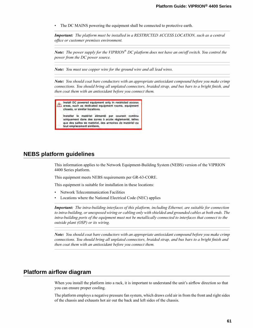
• The DC MAINS powering the equipment shall be connected to protective earth.
Important: The platform must be installed in a RESTRICTED ACCESS LOCATION, such as a centraloffice or customer premises environment.
Note: The power supply for the VIPRION® DC platform does not have an on/off switch. You control thepower from the DC power source.
Note: You must use copper wire for the ground wire and all lead wires.
Note: You should coat bare conductors with an appropriate antioxidant compound before you make crimpconnections. You should bring all unplated connectors, braided strap, and bus bars to a bright finish, andthen coat them with an antioxidant before you connect them.
NEBS platform guidelines
This information applies to the Network Equipment-Building System (NEBS) version of the VIPRION4400 Series platform.
This equipment meets NEBS requirements per GR-63-CORE.
This equipment is suitable for installation in these locations:
• Network Telecommunication Facilities• Locations where the National Electrical Code (NEC) applies
Important: The intra-building interfaces of this platform, including Ethernet, are suitable for connectionto intra-building, or unexposed wiring or cabling only with shielded and grounded cables at both ends. Theintra-building ports of the equipment must not be metallically connected to interfaces that connect to theoutside plant (OSP) or its wiring.
Note: You should coat bare conductors with an appropriate antioxidant compound before you make crimpconnections. You should bring all unplated connectors, braided strap, and bus bars to a bright finish andthen coat them with an antioxidant before you connect them.
Platform airflow diagram
When you install the platform into a rack, it is important to understand the unit’s airflow direction so thatyou can ensure proper cooling.
The platform employs a negative pressure fan system, which draws cold air in from the front and right sidesof the chassis and exhausts hot air out the back and left sides of the chassis.
61
Platform Guide: VIPRION® 4400 Series
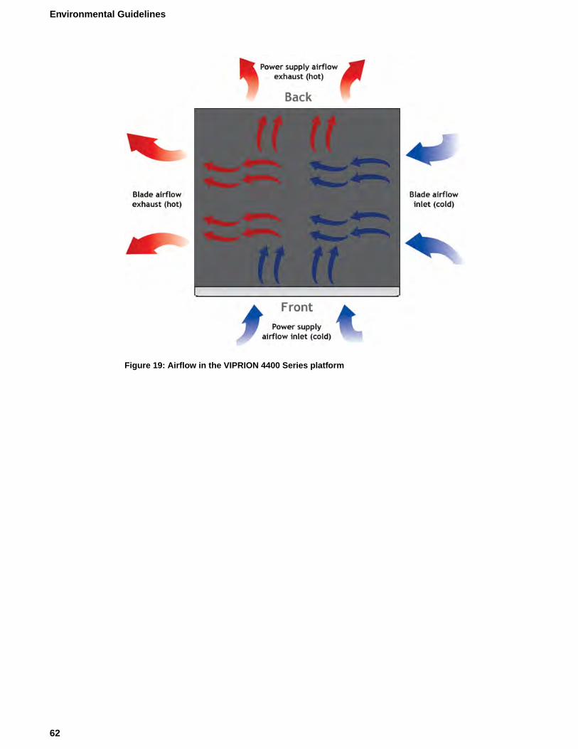
Figure 19: Airflow in the VIPRION 4400 Series platform
62
Environmental Guidelines
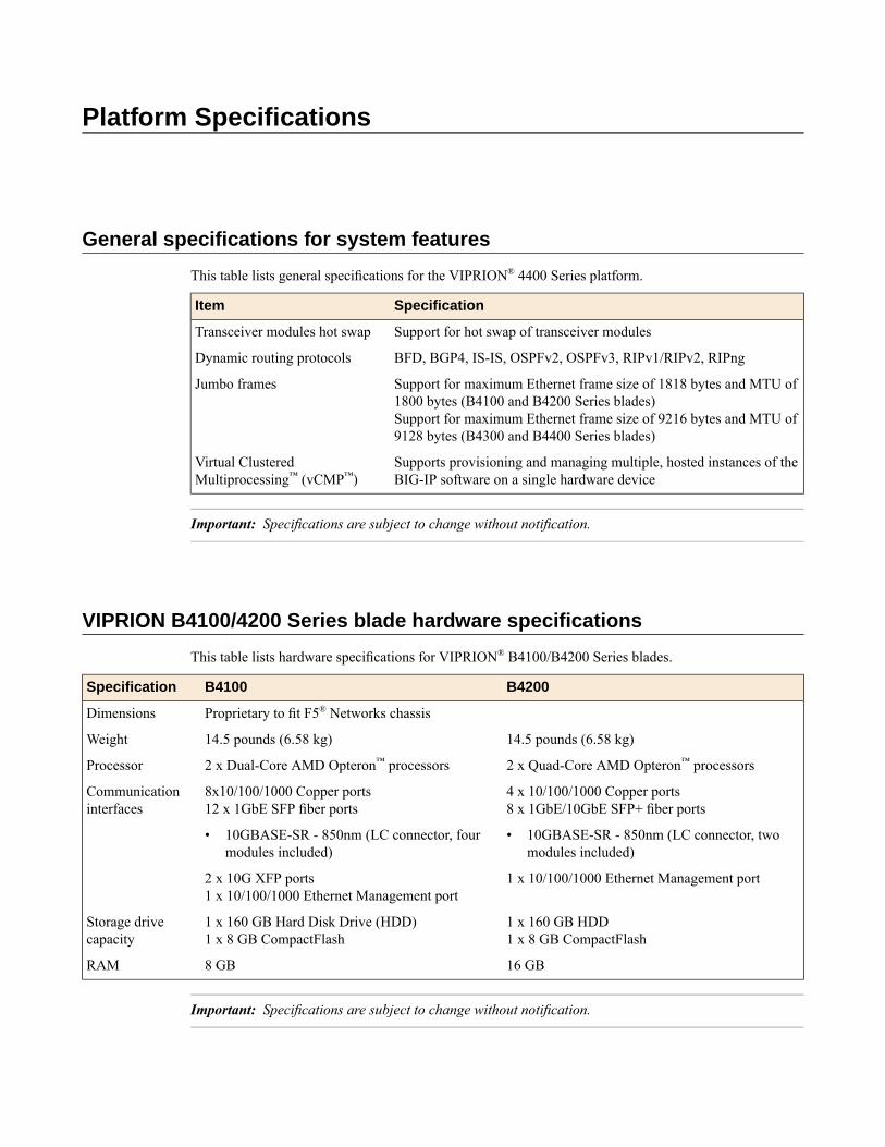
Platform Specifications
General specifications for system features
This table lists general specifications for the VIPRION® 4400 Series platform.
SpecificationItem
Support for hot swap of transceiver modulesTransceiver modules hot swap
BFD, BGP4, IS-IS, OSPFv2, OSPFv3, RIPv1/RIPv2, RIPngDynamic routing protocols
Support for maximum Ethernet frame size of 1818 bytes and MTU of1800 bytes (B4100 and B4200 Series blades)Support for maximum Ethernet frame size of 9216 bytes and MTU of9128 bytes (B4300 and B4400 Series blades)
Jumbo frames
Supports provisioning and managing multiple, hosted instances of theBIG-IP software on a single hardware device
Virtual ClusteredMultiprocessing™ (vCMP™)
Important: Specifications are subject to change without notification.
VIPRION B4100/4200 Series blade hardware specifications
This table lists hardware specifications for VIPRION® B4100/B4200 Series blades.
B4200B4100Specification
Proprietary to fit F5® Networks chassisDimensions
14.5 pounds (6.58 kg)14.5 pounds (6.58 kg)Weight
2 x Quad-Core AMD Opteron™ processors2 x Dual-Core AMD Opteron™ processorsProcessor
4 x 10/100/1000 Copper ports8 x 1GbE/10GbE SFP+ fiber ports
8x10/100/1000 Copper ports12 x 1GbE SFP fiber ports
Communicationinterfaces
• 10GBASE-SR - 850nm (LC connector, twomodules included)
• 10GBASE-SR - 850nm (LC connector, fourmodules included)
2 x 10G XFP ports 1 x 10/100/1000 Ethernet Management port1 x 10/100/1000 Ethernet Management port
1 x 160 GB HDD1 x 8 GB CompactFlash
1 x 160 GB Hard Disk Drive (HDD)1 x 8 GB CompactFlash
Storage drivecapacity
16 GB8 GBRAM
Important: Specifications are subject to change without notification.
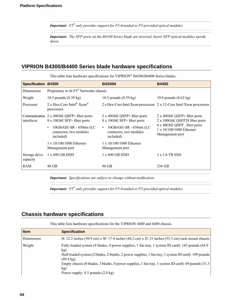
Important: F5® only provides support for F5-branded or F5-provided optical modules.
Important: The XFP ports on the B4100 Series blade are inverted. Insert XFP optical modules upsidedown.
VIPRION B4300/B4400 Series blade hardware specifications
This table lists hardware specifications for VIPRION® B4300/B4400 Series blades.
B4450B4340NB4300Specification
Proprietary to fit F5® Networks chassisDimensions
19.0 pounds (8.62 kg)18.5 pounds (8.39 kg)18.5 pounds (8.39 kg)Weight
2 x 12-Core Intel Xeon processors2 x Hex-Core Intel Xeon processors2 x Hex-Core Intel® Xeon®processors
Processor
2 x 40GbE QSFP+ fiber ports2 x 100GbE QSFP28 fiber ports
2 x 40GbE QSFP+ fiber ports8 x 10GbE SFP+ fiber ports
2 x 40GbE QSFP+ fiber ports8 x 10GbE SFP+ fiber ports
Communicationinterfaces
6 x 40GbE QSFP_ fiber ports•• 10GBASE-SR - 850nm (LCconnector, two modulesincluded)
10GBASE-SR - 850nm (LCconnector, two modulesincluded)
1 x 10/100/1000 EthernetManagement port
1 x 10/100/1000 EthernetManagement port
1 x 10/100/1000 EthernetManagement port
1 x 1.6 TB SSD1 x 600 GB HDD1 x 600 GB HDDStorage drivecapacity
256 GB96 GB48 GBRAM
Important: Specifications are subject to change without notification.
Important: F5® only provides support for F5-branded or F5-provided optical modules.
Chassis hardware specifications
This table lists hardware specifications for the VIPRION 4400 and 4480 chassis.
SpecificationItem
H: 12.2 inches (30.9 cm) x W: 17.4 inches (44.2 cm) x D: 21 inches (53.3 cm) rack-mount chassisDimensions
Fully-loaded system (4 blades, 4 power supplies, 1 fan tray, 1 system ID card): 143 pounds (64.9kg)Half-loaded system (2 blades, 2 blanks, 2 power supplies, 1 fan tray, 1 system ID card): 109 pounds(49.4 kg)
Weight
Empty chassis (0 blades, 3 blanks, 0 power supplies, 1 fan tray, 1 system ID card): 69 pounds (31.3kg)Power supply: 4.5 pounds (2.0 kg)
64
Platform Specifications
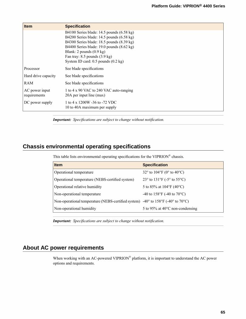
SpecificationItemB4100 Series blade: 14.5 pounds (6.58 kg)B4200 Series blade: 14.5 pounds (6.58 kg)B4300 Series blade: 18.5 pounds (8.39 kg)B4400 Series blade: 19.0 pounds (8.62 kg)Blank: 2 pounds (0.9 kg)Fan tray: 8.5 pounds (3.9 kg)System ID card: 0.5 pounds (0.2 kg)
See blade specificationsProcessor
See blade specificationsHard drive capacity
See blade specificationsRAM
1 to 4 x 90 VAC to 240 VAC auto-ranging20A per input line (max)
AC power inputrequirements
1 to 4 x 1200W -36 to -72 VDC10 to 40A maximum per supply
DC power supply
Important: Specifications are subject to change without notification.
Chassis environmental operating specifications
This table lists environmental operating specifications for the VIPRION® chassis.
SpecificationItem
32° to 104°F (0° to 40°C)Operational temperature
23° to 131°F (-5° to 55°C)Operational temperature (NEBS-certified system)
5 to 85% at 104°F (40°C)Operational relative humidity
-40 to 158°F (-40 to 70°C)Non-operational temperature
-40° to 158°F (-40° to 70°C)Non-operational temperature (NEBS-certified system)
5 to 95% at 40°C non-condensingNon-operational humidity
Important: Specifications are subject to change without notification.
About AC power requirements
When working with an AC-powered VIPRION® platform, it is important to understand the AC poweroptions and requirements.
65
Platform Guide: VIPRION® 4400 Series
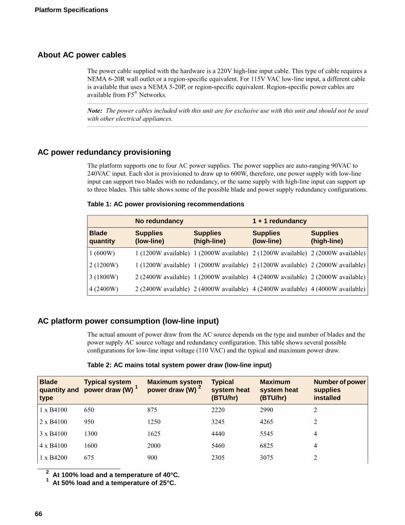
About AC power cables
The power cable supplied with the hardware is a 220V high-line input cable. This type of cable requires aNEMA 6-20R wall outlet or a region-specific equivalent. For 115V VAC low-line input, a different cableis available that uses a NEMA 5-20P, or region-specific equivalent. Region-specific power cables areavailable from F5® Networks.
Note: The power cables included with this unit are for exclusive use with this unit and should not be usedwith other electrical appliances.
AC power redundancy provisioning
The platform supports one to four AC power supplies. The power supplies are auto-ranging 90VAC to240VAC input. Each slot is provisioned to draw up to 600W, therefore, one power supply with low-lineinput can support two blades with no redundancy, or the same supply with high-line input can support upto three blades. This table shows some of the possible blade and power supply redundancy configurations.
Table 1: AC power provisioning recommendations
1 + 1 redundancyNo redundancy
Supplies(high-line)
Supplies(low-line)
Supplies(high-line)
Supplies(low-line)
Bladequantity
2 (2000W available)2 (1200W available)1 (2000W available)1 (1200W available)1 (600W)
2 (2000W available)2 (1200W available)1 (2000W available)1 (1200W available)2 (1200W)
2 (2000W available)4 (2400W available)1 (2000W available)2 (2400W available)3 (1800W)
4 (4000W available)4 (2400W available)2 (4000W available)2 (2400W available)4 (2400W)
AC platform power consumption (low-line input)
The actual amount of power draw from the AC source depends on the type and number of blades and thepower supply AC source voltage and redundancy configuration. This table shows several possibleconfigurations for low-line input voltage (110 VAC) and the typical and maximum power draw.
Table 2: AC mains total system power draw (low-line input)
Number of powersuppliesinstalled
Maximumsystem heat(BTU/hr)
Typicalsystem heat(BTU/hr)
Maximum systempower draw (W) 2
Typical systempower draw (W) 1
Bladequantity andtype
2299022208756501 x B4100
24265324512509502 x B4100
455454440162513003 x B4100
468255460200016004 x B4100
2307523059006751 x B4200
2 At 100% load and a temperature of 40°C.1 At 50% load and a temperature of 25°C.
66
Platform Specifications
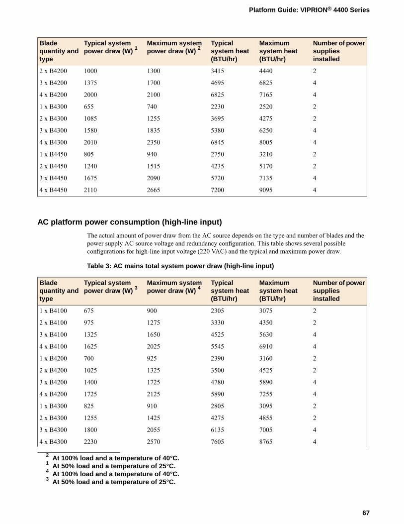
Number of powersuppliesinstalled
Maximumsystem heat(BTU/hr)
Typicalsystem heat(BTU/hr)
Maximum systempower draw (W) 2
Typical systempower draw (W) 1
Bladequantity andtype
244403415130010002 x B4200
468254695170013753 x B4200
471656825210020004 x B4200
2252022307406551 x B4300
242753695125510852 x B4300
462505380183515803 x B4300
480056845235020104 x B4300
2321027509408051 x B4450
251704235151512402 x B4450
471355720209016753 x B4450
490957200266521104 x B4450
AC platform power consumption (high-line input)
The actual amount of power draw from the AC source depends on the type and number of blades and thepower supply AC source voltage and redundancy configuration. This table shows several possibleconfigurations for high-line input voltage (220 VAC) and the typical and maximum power draw.
Table 3: AC mains total system power draw (high-line input)
Number of powersuppliesinstalled
Maximumsystem heat(BTU/hr)
Typicalsystem heat(BTU/hr)
Maximum systempower draw (W) 4
Typical systempower draw (W) 3
Bladequantity andtype
2307523059006751 x B4100
24350333012759752 x B4100
456304525165013253 x B4100
469105545202516254 x B4100
2316023909257001 x B4200
245253500132510252 x B4200
458904780172514003 x B4200
472555890212517254 x B4200
2309528059108251 x B4300
248554275142512552 x B4300
470056135205518003 x B4300
487657605257022304 x B4300
2 At 100% load and a temperature of 40°C.1 At 50% load and a temperature of 25°C.4 At 100% load and a temperature of 40°C.3 At 50% load and a temperature of 25°C.
67
Platform Guide: VIPRION® 4400 Series
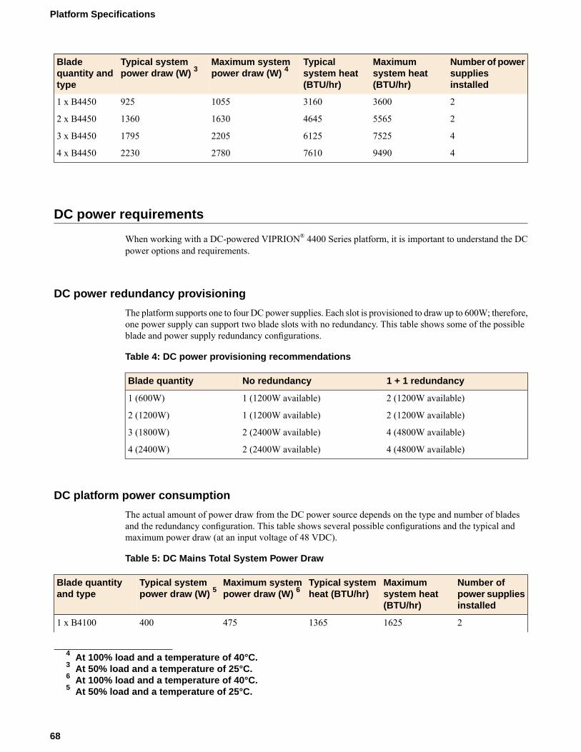
Number of powersuppliesinstalled
Maximumsystem heat(BTU/hr)
Typicalsystem heat(BTU/hr)
Maximum systempower draw (W) 4
Typical systempower draw (W) 3
Bladequantity andtype
23600316010559251 x B4450
255654645163013602 x B4450
475256125220517953 x B4450
494907610278022304 x B4450
DC power requirements
When working with a DC-powered VIPRION® 4400 Series platform, it is important to understand the DCpower options and requirements.
DC power redundancy provisioning
The platform supports one to four DC power supplies. Each slot is provisioned to draw up to 600W; therefore,one power supply can support two blade slots with no redundancy. This table shows some of the possibleblade and power supply redundancy configurations.
Table 4: DC power provisioning recommendations
1 + 1 redundancyNo redundancyBlade quantity
2 (1200W available)1 (1200W available)1 (600W)
2 (1200W available)1 (1200W available)2 (1200W)
4 (4800W available)2 (2400W available)3 (1800W)
4 (4800W available)2 (2400W available)4 (2400W)
DC platform power consumption
The actual amount of power draw from the DC power source depends on the type and number of bladesand the redundancy configuration. This table shows several possible configurations and the typical andmaximum power draw (at an input voltage of 48 VDC).
Table 5: DC Mains Total System Power Draw
Number ofpower suppliesinstalled
Maximumsystem heat(BTU/hr)
Typical systemheat (BTU/hr)
Maximum systempower draw (W) 6
Typical systempower draw (W) 5
Blade quantityand type
2162513654754001 x B4100
4 At 100% load and a temperature of 40°C.3 At 50% load and a temperature of 25°C.6 At 100% load and a temperature of 40°C.5 At 50% load and a temperature of 25°C.
68
Platform Specifications
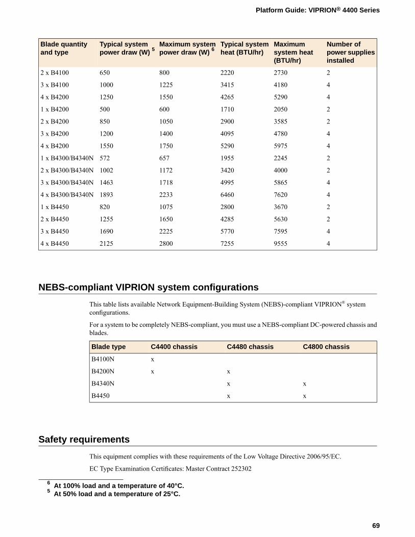
Number ofpower suppliesinstalled
Maximumsystem heat(BTU/hr)
Typical systemheat (BTU/hr)
Maximum systempower draw (W) 6
Typical systempower draw (W) 5
Blade quantityand type
2273022208006502 x B4100
441803415122510003 x B4100
452904265155012504 x B4200
2205017106005001 x B4200
23585290010508502 x B4200
447804095140012003 x B4200
459755290175015504 x B4200
2224519556575721 x B4300/B4340N
240003420117210022 x B4300/B4340N
458654995171814633 x B4300/B4340N
476206460223318934 x B4300/B4340N
23670280010758201 x B4450
256304285165012552 x B4450
475955770222516903 x B4450
495557255280021254 x B4450
NEBS-compliant VIPRION system configurations
This table lists available Network Equipment-Building System (NEBS)-compliant VIPRION® systemconfigurations.
For a system to be completely NEBS-compliant, you must use a NEBS-compliant DC-powered chassis andblades.
C4800 chassisC4480 chassisC4400 chassisBlade type
xB4100N
xxB4200N
xxB4340N
xxB4450
Safety requirements
This equipment complies with these requirements of the Low Voltage Directive 2006/95/EC.
EC Type Examination Certificates: Master Contract 252302
6 At 100% load and a temperature of 40°C.5 At 50% load and a temperature of 25°C.
69
Platform Guide: VIPRION® 4400 Series

CB Scheme
EN 60950-1:2006+A11:2009+A1:2010+A12:2011
IEC 60950-1:2005, A1:2009
CSA 60950-1-07, including A1:2011+A2:2014
ANSI/UL 60950-1-2011
Important: Specifications are subject to change without notification.
EMC requirements
This equipment complies with these EMC requirements.
USA--FCC Class A, Canada--Industry Canada Class A
This equipment complies with Part 15 of the FCC Rules. Operation is subject to these conditions:
• This equipment may not cause harmful interference.• This device must accept any interference received, including interference that may cause undesired
operation.
European Union
This equipment complies with these requirements of the EMC Directive 2004/108/EC:
As Telecommunication Network Equipment (TNE) in Both Telecom Centers and Other Than TelecomCenters per (as applicable):
Required Limits:Directive:
300 386 V1.6.1 (2012)ETSI EN
Class AEN 55022:2012
EN 61000-3-2:2014
EN 61000-3-3:2013
As Information Technology Equipment (ITE) Class A per (as applicable):
Required Limits:Directive:
EN 55024:2010
Class AEN 55032:2012
EN 61000-3-2:2014
EN 61000-3-3:2013
Important: Specifications are subject to change without notification.
70
Platform Specifications

Acoustic, airflow, and altitude specifications
This table lists acoustic levels, airflow movement, and operational altitude specifications for the VIPRION4400 Series platform.
Chassis with bladeUnitsDetailSpecification type
7277
dBAdBA
FrontLeft
Acoustic 7
75dBARight67dBARear
5905FeetOperationalAltitude 8
40,000FeetNon-operational
650CFMEntire chassisAirflow 9
Important: Specifications are subject to change without notification.
7 All measurements taken at 0.6 meter with one power supply operational and fans at 75% duty cycle. Measurementsrecorded in Decibels A-weighting.
8 Per BELCOREGR-63-CORE, section 4.1.3: This unit is functional when installed at elevations between 60m (197 feet)below sea level and 1800m (6000 feet) above sea level at the aisle ambient temperatures of 40°C.
9 Fan Tray airflow measurements taken at 100% duty cycle and in open air.
71
Platform Guide: VIPRION® 4400 Series


China RoHS Requirements
Hazardous substance levels for China
This table shows how the VIPRION® 4400 Series platform components conform to the Restriction ofHazardous substances Directive (RoHS) standards for China.
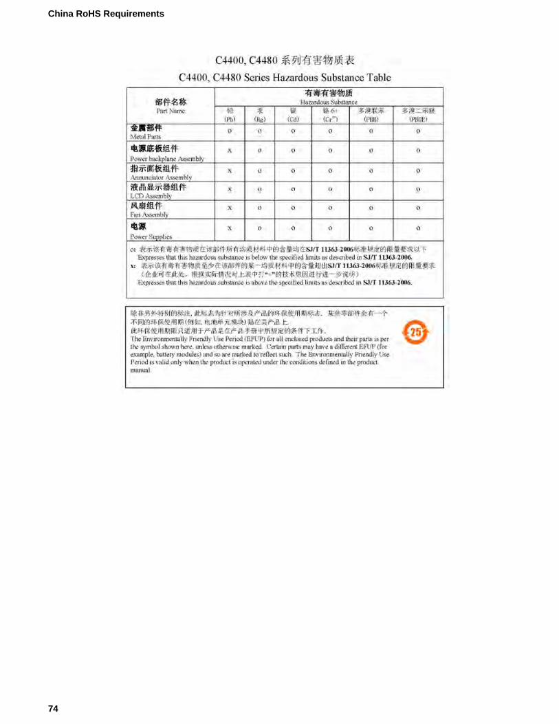
74
China RoHS Requirements
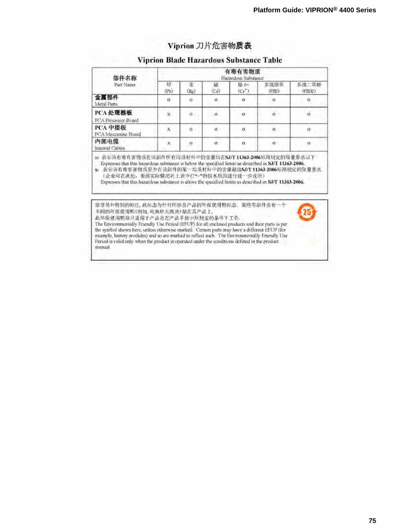
75
Platform Guide: VIPRION® 4400 Series
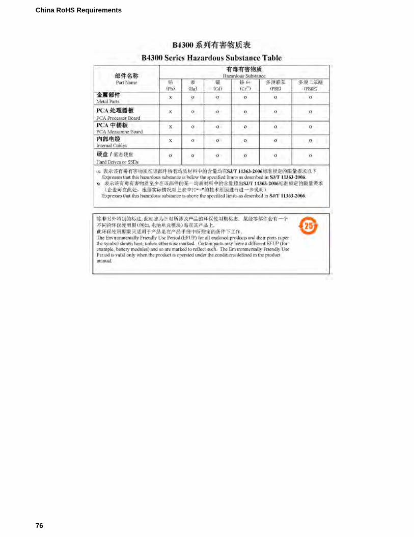
76
China RoHS Requirements
77
Platform Guide: VIPRION® 4400 Series

Repackaging Guidelines
About repackaging the platform
The VIPRION® 4400 Series chassis and blades are designed to be shipped and packaged separately. If itbecomes necessary to transport the platform to another location or return it to F5®Networks, these guidelineswill help ensure that you repackage the platform properly.
Important: Before returning any equipment, contact F5 to obtain a Return Material Authorization (RMA)case number.
Important: Youmust use shipping materials and packaging provided by F5 when repackaging the platform.
Note: Be sure to keep a record of the tracking number and ship date. These will be needed to track lostshipments.
Note: Do not include any cables, removable XFP/SFP/SFP+ modules, GBICs, or other peripheral itemsif you are returning the platform to F5 Networks.
Repackaging the chassis
The VIPRION® 4400 Series chassis must be shipped empty (with no blades installed) and in F5®-providedpackaging.
1. Disconnect the power cords and other cables from the platform.2. Remove the front bezel from the chassis and place it in the bezel box.3. (Optional) You can install the chassis handles if they are not already installed to help ease removal of
the chassis from the rack.4. Remove all blades from the chassis.5. Remove the chassis from the rack.6. Place the empty chassis onto the shipping pallet.
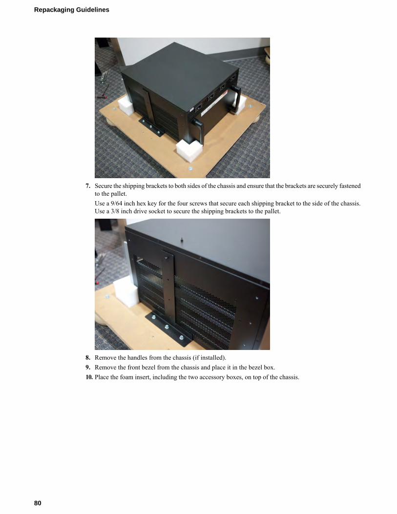
7. Secure the shipping brackets to both sides of the chassis and ensure that the brackets are securely fastenedto the pallet.Use a 9/64 inch hex key for the four screws that secure each shipping bracket to the side of the chassis.Use a 3/8 inch drive socket to secure the shipping brackets to the pallet.
8. Remove the handles from the chassis (if installed).9. Remove the front bezel from the chassis and place it in the bezel box.10. Place the foam insert, including the two accessory boxes, on top of the chassis.
80
Repackaging Guidelines
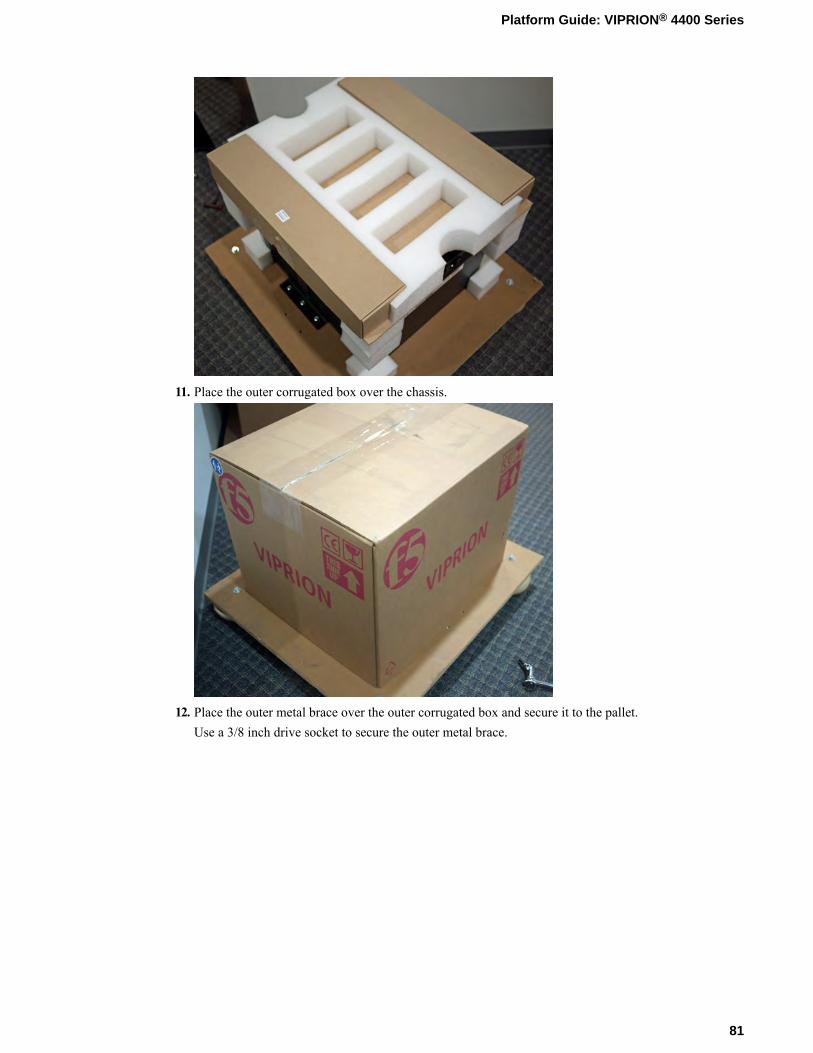
11. Place the outer corrugated box over the chassis.
12. Place the outer metal brace over the outer corrugated box and secure it to the pallet.Use a 3/8 inch drive socket to secure the outer metal brace.
81
Platform Guide: VIPRION® 4400 Series
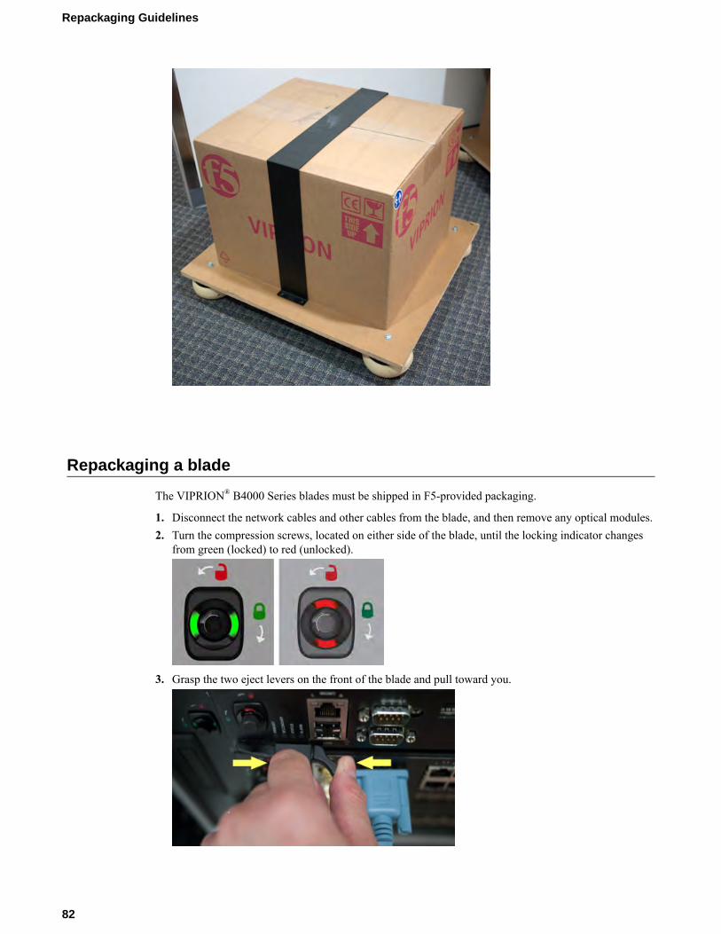
Repackaging a blade
The VIPRION® B4000 Series blades must be shipped in F5-provided packaging.
1. Disconnect the network cables and other cables from the blade, and then remove any optical modules.2. Turn the compression screws, located on either side of the blade, until the locking indicator changes
from green (locked) to red (unlocked).
3. Grasp the two eject levers on the front of the blade and pull toward you.
82
Repackaging Guidelines
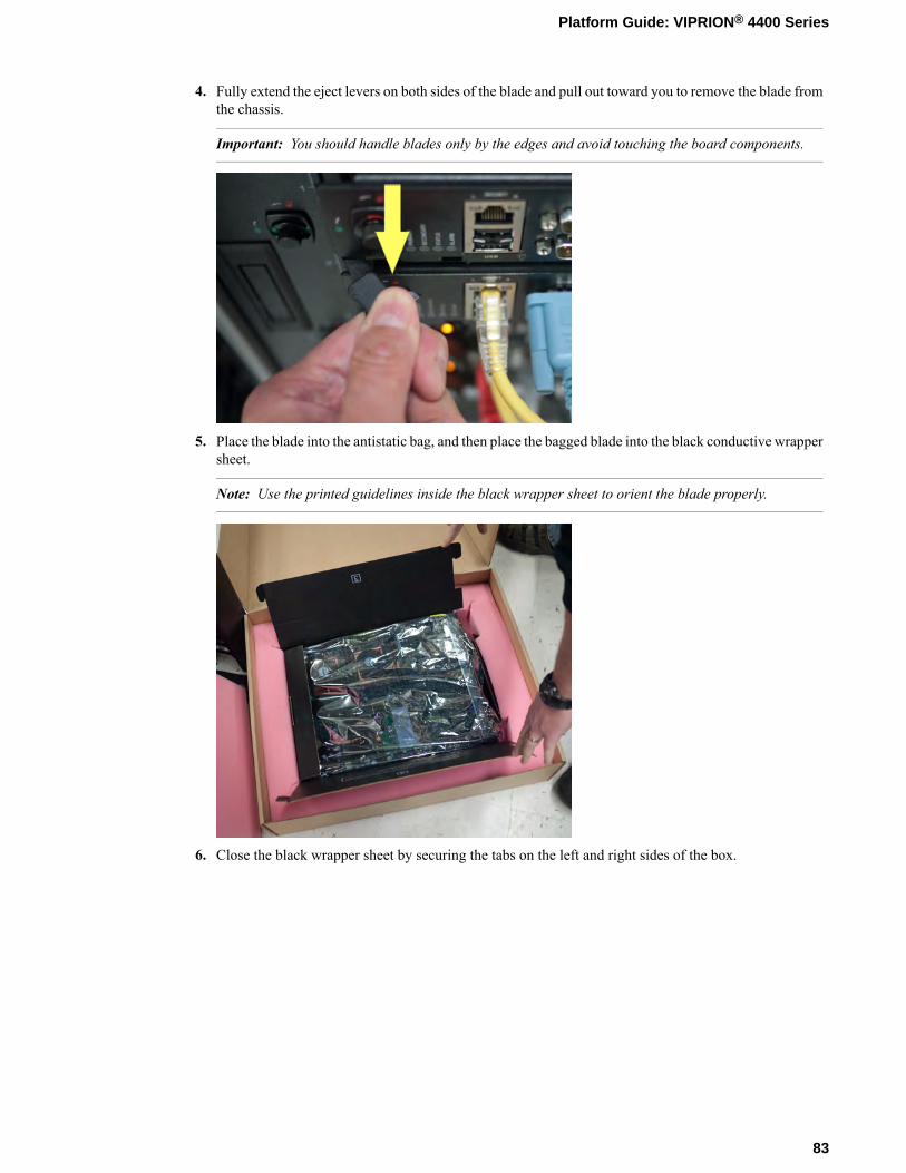
4. Fully extend the eject levers on both sides of the blade and pull out toward you to remove the blade fromthe chassis.
Important: You should handle blades only by the edges and avoid touching the board components.
5. Place the blade into the antistatic bag, and then place the bagged blade into the black conductive wrappersheet.
Note: Use the printed guidelines inside the black wrapper sheet to orient the blade properly.
6. Close the black wrapper sheet by securing the tabs on the left and right sides of the box.
83
Platform Guide: VIPRION® 4400 Series
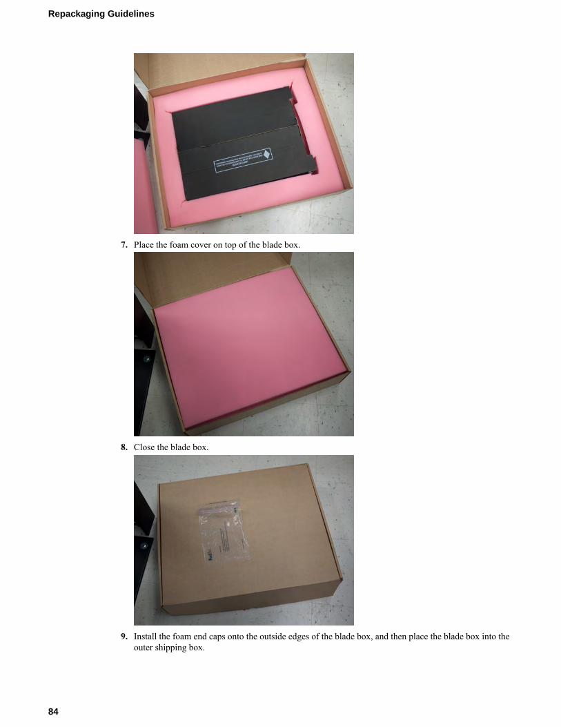
7. Place the foam cover on top of the blade box.
8. Close the blade box.
9. Install the foam end caps onto the outside edges of the blade box, and then place the blade box into theouter shipping box.
84
Repackaging Guidelines
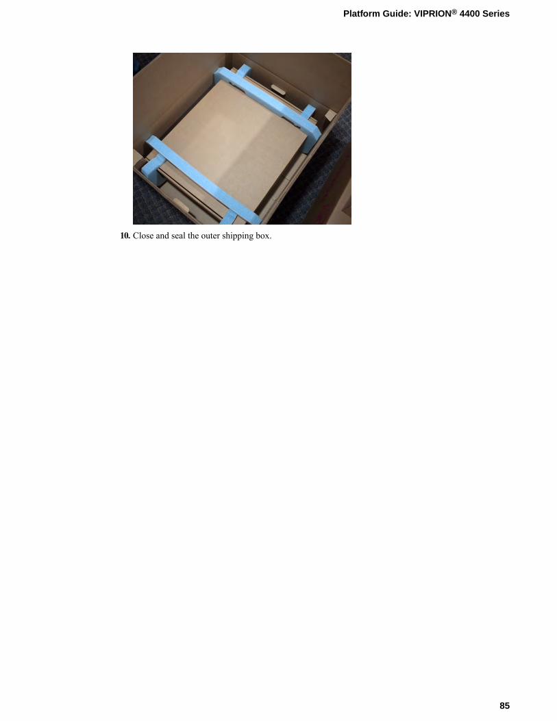
10. Close and seal the outer shipping box.
85
Platform Guide: VIPRION® 4400 Series


Returned Material Data Security Statement
About returned material data security
Follow these data security guidelines when returning equipment to F5® for reprocessing or repair. Theguidelines include reprocessing procedures and optional customer-end procedures.
About memory technologies used in F5 equipment
F5® equipment contains volatile, battery-backed volatile, and non-volatile memory. Volatile memory losesall traces of data on power down. Battery-backed volatile memory retains data as long as battery charge ismaintained. Non-volatile memory retains data indefinitely.
Volatile memory
Volatile memory loses all traces of data on power down; therefore, customer data that is stored in volatilememory is secure when power is removed from the platform. No further action is required by customersfor equipment that includes volatile memory.
Battery-backed volatile memory
This F5® platform contains a coin battery for maintaining BIOS settings and the system clock. All datamaintained by the coin battery is used only for system specific tasks. No customer data is maintained bythe battery-backed volatile memory. No further action is required by customers for equipment that includesvolatile memory.
Non-volatile memory
F5® platforms include various non-volatile memory components. These non-volatile memory componentscan be categorized as either user inaccessible or user accessible.
Inaccessible non-volatile memory components are programmed during manufacture or software installation.The data stored in user inaccessible non-volatile memory is used for setting voltage levels, determining thesequence of operational events, and the managing appliance operational condition. Data held within userinaccessible, non-volatilememory represents no data security risk to customers. User inaccessible, non-volatilememory cannot be modified by appliance users, and therefore, contains no customer data.
Inaccessible non-volatile memory
This table lists the inaccessible non-volatile memory in this system.
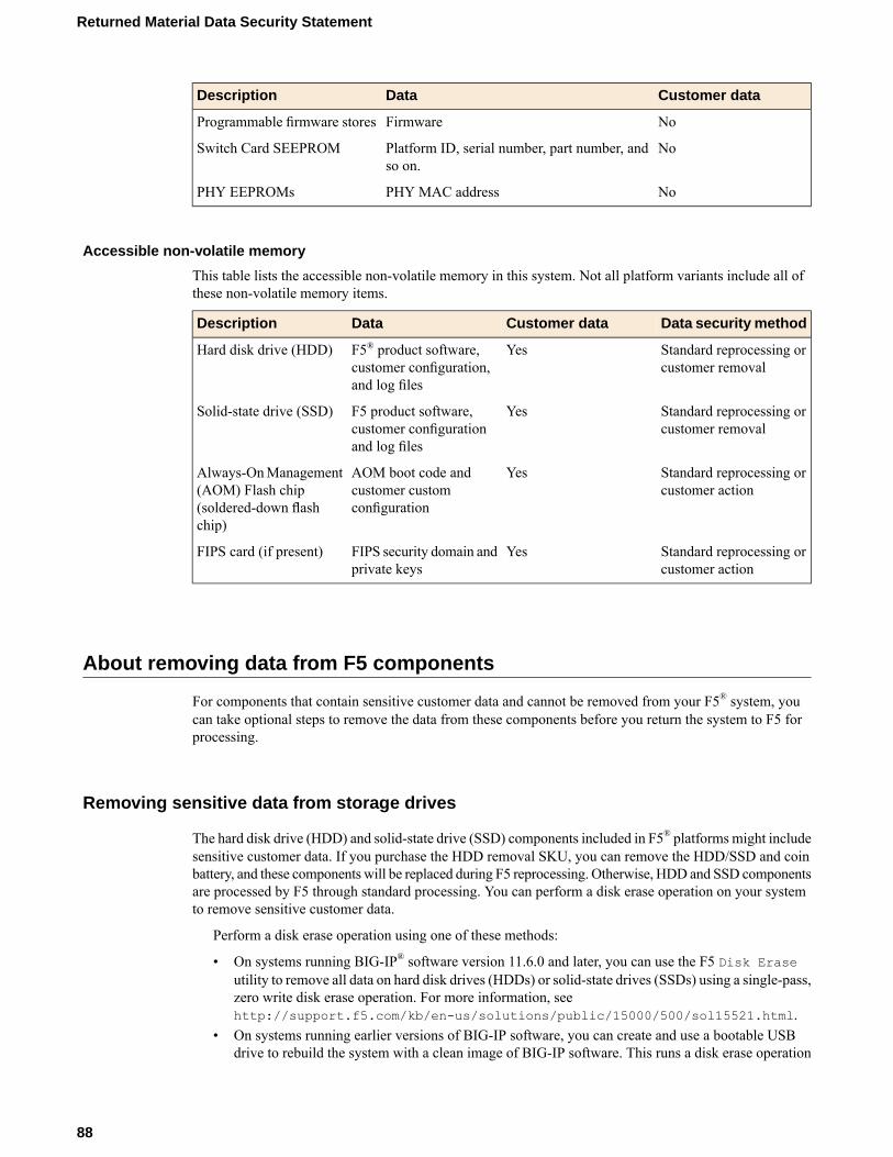
Customer dataDataDescription
NoFirmwareProgrammable firmware stores
NoPlatform ID, serial number, part number, andso on.
Switch Card SEEPROM
NoPHY MAC addressPHY EEPROMs
Accessible non-volatile memory
This table lists the accessible non-volatile memory in this system. Not all platform variants include all ofthese non-volatile memory items.
Data security methodCustomer dataDataDescription
Standard reprocessing orcustomer removal
YesF5® product software,customer configuration,and log files
Hard disk drive (HDD)
Standard reprocessing orcustomer removal
YesF5 product software,customer configurationand log files
Solid-state drive (SSD)
Standard reprocessing orcustomer action
YesAOM boot code andcustomer customconfiguration
Always-OnManagement(AOM) Flash chip(soldered-down flashchip)
Standard reprocessing orcustomer action
YesFIPS security domain andprivate keys
FIPS card (if present)
About removing data from F5 components
For components that contain sensitive customer data and cannot be removed from your F5® system, youcan take optional steps to remove the data from these components before you return the system to F5 forprocessing.
Removing sensitive data from storage drives
The hard disk drive (HDD) and solid-state drive (SSD) components included in F5® platforms might includesensitive customer data. If you purchase the HDD removal SKU, you can remove the HDD/SSD and coinbattery, and these components will be replaced during F5 reprocessing. Otherwise, HDD and SSD componentsare processed by F5 through standard processing. You can perform a disk erase operation on your systemto remove sensitive customer data.
Perform a disk erase operation using one of these methods:
• On systems running BIG-IP® software version 11.6.0 and later, you can use the F5 Disk Eraseutility to remove all data on hard disk drives (HDDs) or solid-state drives (SSDs) using a single-pass,zero write disk erase operation. For more information, seehttp://support.f5.com/kb/en-us/solutions/public/15000/500/sol15521.html.
• On systems running earlier versions of BIG-IP software, you can create and use a bootable USBdrive to rebuild the system with a clean image of BIG-IP software. This runs a disk erase operation
88
Returned Material Data Security Statement
and removes the master boot record (MBR). For more information seehttp://support.f5.com/kb/en-us/solutions/public/13000/100/sol13164.html.
Removing IP address data from Always-On Management
If you have configured an IP address for the Always-On Management (AOM) subsystem, you can removethe customized IP address from the system before returning it to F5® Networks.
1. Connect to the system using the serial console.2. Open the AOM Command Menu.
Esc (
3. Assign a new management IP address, netmask, and gateway:
• To use DHCP to assign the addresses, type y when prompted about using DHCP.• To manually assign the addresses, type n when prompted about using DHCP. At the prompts, type
values for IP address (required), netmask (required), and gateway (optional).
A confirmation message displays the configured management IP address, netmask, and gateway.4. (Optional) Type i to verify the assigned addresses.
Removing sensitive data from an internal hardware security module (HSM)
If the system includes an internal hardware security module (HSM), also referred to as a FIPS card, youcan remove the sensitive customer data from HSM before returning it to F5® Networks.
Important: The HSM cannot be removed from the platform.
1. Use the Configuration utility to delete all key/certificate pairs.a) On the Main tab, click System > File Management > SSL Certificate List.
This displays the list of certificates installed on the system.b) Select the certificates that you want to delete and click Delete.
This removes all .crt, .exp, and .key files from the system.
2. Log in to the command line of the system using an account with root access.3. Initialize the HSM and reconfigure it using fictitious data.
run util fips-util -f init
For more information on using this command on a FIPS platform, see BIG-IP® Platform: FIPSAdministration.
Important: This deletes all keys and makes any previously exported keys unusable.
89
Platform Guide: VIPRION® 4400 Series


Legal Notices
Legal Notices
Publication Date
This document was published on August 17, 2017.
Publication Number
MAN-0311-09
Copyright
Copyright © 2017, F5 Networks, Inc. All rights reserved.
F5 Networks, Inc. (F5) believes the information it furnishes to be accurate and reliable. However, F5 assumesno responsibility for the use of this information, nor any infringement of patents or other rights of thirdparties which may result from its use. No license is granted by implication or otherwise under any patent,copyright, or other intellectual property right of F5 except as specifically described by applicable userlicenses. F5 reserves the right to change specifications at any time without notice.
Trademarks
For a current list of F5 trademarks and service marks, seehttp://www.f5.com/about/guidelines-policies/trademarks/.
All other product and company names herein may be trademarks of their respective owners.
Patents
This product may be protected by one or more patents indicated at: https://f5.com/about-us/policies/patents
Export Regulation Notice
This product may include cryptographic software. Under the Export Administration Act, the United Statesgovernment may consider it a criminal offense to export this product from the United States.
RF Interference Warning
This is a Class A product. In a domestic environment this product may cause radio interference, in whichcase the user may be required to take adequate measures.
FCC Compliance
This equipment has been tested and found to comply with the limits for a Class A digital device pursuantto Part 15 of FCC rules. These limits are designed to provide reasonable protection against harmfulinterference when the equipment is operated in a commercial environment. This unit generates, uses, andcan radiate radio frequency energy and, if not installed and used in accordance with the instruction manual,may cause harmful interference to radio communications. Operation of this equipment in a residential areais likely to cause harmful interference, in which case the user, at his own expense, will be required to takewhatever measures may be required to correct the interference.

Anymodifications to this device, unless expressly approved by themanufacturer, can void the user's authorityto operate this equipment under part 15 of the FCC rules.
Canadian Regulatory Compliance
This Class A digital apparatus complies with Canadian ICES-003.
Standards Compliance
This product conforms to the IEC, European Union, ANSI/UL and Canadian CSA standards applicable toInformation Technology products at the time of manufacture.
VCCI Class A Compliance
This is a Class A product. In a domestic environment, this product may cause radio interference, in whichcase the user may be required to take corrective actions. VCCI-A
92
Legal Notices

Index
100GbE interfacesabout 19configuring bundling using tmsh 19configuring FEC using tmsh 20
10GbE interfaces 1610G direct attach copper cables 2640GbE interfaces
about 17breakout cable 17bundling 17configuring bundling using tmsh 18ordering components 17
A
AC chassispower consumption with high-line input 67power consumption with low-line input 66
acoustic specifications 71AC platform
powering 42AC power cord
attaching 42AC-powered equipment
cables 66connecting to a power source 42guidelines 60power provisioning 66
AC power requirementsabout 65
AC power supplyabout 51
airflowchassis installation 32specifications 71
Alarm LEDbehavior 15blade standard operating state 14blade status 14chassis standard operating state 13
alertsclearing 12defining custom alerts 15
altitude specificationsoperational 71
AOM IP address dataremoving 89
Auto-MDI/MDIX 22
B
B4100 Series bladesBIG-IP version 10.1 and later 41chassis compatibility 40
B4200 Series bladesBIG-IP version 10.0.x and earlier 41chassis compatibility 40
B4300 Series bladeschassis compatibility 40
B4400 Series bladeschassis compatibility 40
battery replacement 59battery return terminals 44blades
about 9compatibility in chassis 40components provided 29High Availability (HA) status 14installing 36, 39LED status 14performance in mixed clusters 41removing 38software versions in mixed clusters 41verifying availability 49
blanksabout 36removing 37
breakout cable 17
C
cables10G direct attach copper 26connecting 45
CD/DVD-ROM drivessupport for 29
chassisabout 7environmental operating specifications 65grounding 43installing 35operational temperature 65unpacking 30ventilation 59, 61
chassis, ACcomponents provided 27
chassis, DCadditional equipment required 28hardware provided 28
Check buttonclearing alerts 12
China material content listing, See China RoHS Directivestandards.China RoHS Directive standards 73clear alert operation 12cluster default gateway IP address
configuring 48cluster IP address
about 46configuring using config utility 48configuring using LCD 47configuring using tmsh 49
cluster IP subnet maskconfiguring 47
93
Index

cluster memberconfiguring management IP address 48
clustersdefault cluster 46management 46mixed 41
Configuration utilitylicensing the platform 49
config utilityaccessing using serial console 48
console portlocation 9
cooling systemplatform 61
D
data communications equipment (DCE) 22data terminal equipment (DTE) 22Date and Time screen 13DC chassis
power consumption 68DC-powered equipment
connecting 44connecting to power source 45equipment required for installation 28equipment required for powering 43NEBS-certified system configurations 69NEBS platform guidelines 61power provisioning 68terminals 45
DC-powered platformconnecting to a power source 43guidelines 60
DC power supplyabout 52
device service clustering (DSC)45
mixed clusters 42DSC, See device service clustering (DSC).duplex mode 22dynamic routing protocols 63
E
electromagnetic compatibility (EMC) certifications 70electromagnetic interference (EMI) 36electrostatic discharge (ESD) 27, 32, 36, 59EMC certifications 70environmental guidelines 73
See also China RoHS Directive standards.environmental operating specifications 65environmental warnings 73
See also China RoHS Directive standards.ESD, See electrostatic discharge (ESD).Ethernet hubs
requirements 29
F
failover cable 45
failover portlocation 9
fan trayabout 54replacing the fan tray 55
FEC, See Reed-Solomon Forward Error Correction (RS-FEC).FIPS cards, See hardware security module (HSM).front bezel
attaching 36LCD component 57replacing 57
G
Gigabit Ethernet 29grounding the chassis 43ground lug
connecting to ground terminal 44guidelines
AC-powered equipment 60DC-powered platform 60NEBS platform 61
H
handle installation kit 32handle kit
installing 34hard disk drive (HDD)
about 56hardware
AC-powered equipment 60DC-powered platform 60
hardware installationplanning 27, 32
hardware requirementsperipherals 29
hardware security module (HSM)removing data 89
hardware specifications64
B4100 Series blades 63B4200 Series blades 63B4300 Series blades 64B4400 Series blades 64
hard-wired failover 45hazardous substance restrictions, See China RoHS Directivestandards.Hold mode 11hot swap
of power supply 51of transceiver modules 63
hubs 29
I
indicator LEDsabout 13actions 13alert conditions 15blades 14chassis 14
94
Index

interface commandvalid media types 23
interface mode 22interfaces
100GbE 1940GbE 17configuring 20duplex mode 22managing 20media type 22viewing status of all interfaces using Configuration utility22viewing status of all interfaces using tmsh 20viewing status of a specific interface using tmsh 20viewing valid media types 23
isolated DC return 44
J
jumbo frames 63
L
LCD component 36, 57LCD menus 12LCD panel
about 11backlight option 12brightness option 12contrast option 12control buttons 12menus 12pausing on a screen 11using 11
licenseconfiguring 49
M
maintenanceAC power supply 52DC power supply 54fan tray 55front bezel 57
management IP address, See cluster IP address.management IP address for cluster member, See clustermember.management port
connecting 45location 9
memory technologiesabout 87battery-backed volatile memory 87non-volatile memory 87volatile memory 87
mixed clustersblade compatibility 41blade software versions 41defined 41device service clustering (DSC) 42trunk configuration 42
N
NEBSair temperature 59blades 7chassis 7operational temperature 65platform guidelines 61
NEBS-certified system configurations 69negative pressure fan system 61network interface LEDs
appearance of 24QSFP+ 25QSFP28 26RJ45 24SFP 24SFP+ 25XFP 24
network interface specifications, See transceiver modulespecifications.non-volatile memory
types 87
O
operational temperature 65optical interfaces
16location 9
Options menu 12
P
pass-through adapter, See RJ45F to RJ45M rolled serialadapter.PB100 blades, See B4100 Series blades.PB200 blades, See B4200 Series blades.pinouts
cables 26specifications 26
platformabout 7cooling system 61installing 27NEBS 7replaceable components 51unpacking 30ventilation 59, 61
platform airflow 61platform specifications 64power cables
AC 66power consumption, AC high-line
4400 chassis 674480 chassis 67
power consumption, AC low-line4400 chassis 664480 chassis 66
power consumption, DC4400 chassis 684480 chassis 68
95
Index

power provisioning, AC4400 chassis 664480 chassis 66
power provisioning, DC4400 chassis 684480 chassis 68
power supplyinstalling an AC power supply 52replacing a DC power supply 54
Product version screen 13
Q
qkview utility 45QSFP+ interfaces
See also 40GbE interfaces.configuring bundling using the Configuration utility 19LEDs 25See also 40GbE interfaces.
QSFP28, See 100GbE interfaces.QSFP28 interfaces
See also 100GbE interfaces.LEDs 26See also 100GbE interfaces.
R
rack mountbracket installation 33brackets 27chassis spacing 27general environmental guidelines 59
rack mount installation19-inch rack 3223-inch rack 32
rack mount kitabout 32
redundancysystem 45
redundant system configuration, See device service clustering(DSC).Reed-Solomon Forward Error Correction (RS-FEC)
configuring 20remote administration 29repackaging
about 79blades 82chassis 79
replaceable componentsabout 51AC power supply 51DC power supply 52fan tray 54front bezel 57hard disk drive (HDD) 56
returned material data securityabout 87accessible non-volatile memory 88battery-backed volatile memory 87inaccessible non-volatile memory 87memory technologies 87non-volatile memory 87
returned material data security (continued)removing data from components 88volatile memory 87
RJ45F to RJ45M rolled serial adapter 45RJ45 interface LEDs 24RMA 79Rotate mode 11RS-FEC, See Reed-Solomon Forward Error Correction(RS-FEC).
S
safety agency approvals 69Screens menu 13serial console
hardware installation 29, 45serial failover 45SFP+ interface LEDs 25SFP hot swap 63SFP interface LEDs 24specifications
acoustic 71airflow 71altitude 71chassis 64chassis environmental operation 65China RoHS 73system features 63
standard operating stateblade Alarm LED 14blade Status LED 14chassis Alarm LED 13chassis Status LED 13
Status LEDblade standard operating state 14blade status 14chassis standard operating state 13
storage drivereplacing on a B4300 blade 56
storage drivesremoving sensitive data 88
switches 29System menu 12system objects
creating 42
T
tmsh, See Traffic Management Shell.Traffic Management Shell 16transceiver module specifications 26transporting the platform 79trunk configuration
mixed clusters 42
U
unpackingchassis 30
USB flash drivessupport for 29
96
Index

USB portsupported CD/DVD-ROM drives 29
V
vCMP 63ventilation 59, 61VIPRION 4400 chassis
blade compatibility 40supported blades 9
VIPRION 4480 chassisblade compatibility 40
VIPRION system configuration 42Virtual Clustered Multiprocessing, See vCMP.
W
warningsenvironmental 59
X
XFP interface LEDs 24
97
Index

98
Index