PLATE DISPENSER USING PIC ... -...
24
PLATE DISPENSER USING PIC MICROCONTROLLER NURDIYANA BINTI MOHAMED GHAZALI This report is submitted in partial fulfillment of the requirements for the award of Bachelor of Electronic Engineering (Computer Engineering) With Honours Faculty of Electronic and Computer Engineering Universiti Teknikal Malaysia Melaka APRIL 2010
Transcript of PLATE DISPENSER USING PIC ... -...
PLATE DISPENSER USING PIC MICROCONTROLLER
NURDIYANA BINTI MOHAMED GHAZALI
This report is submitted in partial fulfillment of the requirements for the award of Bachelor of Electronic Engineering (Computer Engineering) With Honours
Faculty of Electronic and Computer Engineering Universiti Teknikal Malaysia Melaka
APRIL 2010

UNIVERSTI TEKNIKAL MALAYSIA MELAKA FAKULTI KEJURUTERAAN ELEKTRONIK DAN KEJURUTERAAN KOMPUTER
BORANG PENGESAHAN STATUS LAPORAN
PROJEK SARJANA MUDA II
Tajuk Projek : PLATE DISPENSER USING PIC MICROCONTROLLER Sesi Pengajian : 2009/2010
Saya NURDIYANA BINTI MOHAMED GHAZALI mengaku membenarkan Laporan Projek Sarjana Muda ini disimpan di Perpustakaan dengan syarat-syarat kegunaan seperti berikut:
1. Laporan adalah hakmilik Universiti Teknikal Malaysia Melaka.
2. Perpustakaan dibenarkan membuat salinan untuk tujuan pengajian sahaja.
3. Perpustakaan dibenarkan membuat salinan laporan ini sebagai bahan pertukaran antara institusi
pengajian tinggi.
4. Sila tandakan ( √ ) :
SULIT* (Mengandungi maklumat yang berdarjah keselamatan atau kepentingan Malaysia seperti yang termaktub di dalam AKTA RAHSIA RASMI 1972)
TERHAD* (Mengandungi maklumat terhad yang telah ditentukan oleh organisasi/badan di mana penyelidikan dijalankan)
TIDAK TERHAD
Disahkan oleh:
__________________________ ___________________________________ (TANDATANGAN PENULIS) (COP DAN TANDATANGAN
PENYELIA) Alamat Tetap : NO 1 KAMPUNG KEPAYANG FAIR PARK, 31400 IPOH PERAK.
Tarikh: 30 APRIL 2010 Tarikh: 30 APRIL 2010

iii
“I, hereby declare that this thesis entitled, Plate Dispenser using PIC microcontroller
is a result of my own research idea concept for works that have been cited clearly in
the references.”
SIGNATURE: ………………………………………
NAME : NURDIYANA BINTI MOHAMED GHAZALI
DATE : 30 APRIL 2010

iv
“I, hereby declare that I have read this report an in my opinion this report is sufficient
in terms of scope and quality for the award of Bachelor of Electronic Engineering
(Computer Engineering) With Honours”
SIGNATURE : ………………………………………
SUPERVISOR NAME : MUZALIFAH BINTI MOHD SAID
DATE : 30 APRIL 2010

v
Special dedication to my loving family, all my siblings, and my kind hearted
supervisors Ms. Muzalifah Mohd Said, Ms. Syafeeza Ahmad Radzi and also dearest
friends.
vi
ACKNOWLEDGEMENT
First of all, praise to Allah S.W.T because I can finished up my thesis
smoothly. Apart from the efforts of me, the success of this thesis depends largely on
the encouragement and guidelines of many others. I take this opportunity to express,
my gratitude to the people who have been instrumental in the successful completion
of this project.
On this opportunity, I would like to express my gratitude to the Faculty of
Electronic and Computer, University Teknikal Malaysia Melaka generally and
sincere gratitude to my supervisors, Ms. Muzalifah Bt Mohd Said and Ms. Syafeeza
Ahmad Radzi for their assistance and guidance towards the progress of this project
thesis. Throughout this semester, Ms. Muzalifah and Ms. Syafeeza have been
patiently monitoring my progress and guided me in the right direction and offering
their encouragement to me. Obviously the progress I had now will be uncertain
without their assistance.
I am very grateful to my family especially my mom and dad and not forget
also to my siblings for their unfailing encouragement and financial support that they
have given to me for over the years.
My special appreciation and thanks to all my friends for their invaluable
assistances towards this project thesis. And also to everyone who involve in this
project either direct or indirectly.
Thank you.
vii
ABSTRACT
Plate Dispenser Project is a way to organize a large canteen or cafeteria
systematically. The purpose of this system is to develop a smart cafeteria where the
job of waiter is replaced by a machine. During peak hour, large canteen and food
court always encounter problem where clean plate is unavailable and the dirty plate
is messed up on the table. This problem happens when customers enter a premise in a
large quantity at the same time while the workers are in limited number to do all the
work. The solution for this problem is to develop a system which can ensure the
customer return the used plate in a proper place (machine). When the customer
returns their plate, they will get back their coins that they had inserted during taking
the clean plate. Through this system, a plate can dispense more systematically. This
system is developed the vending machine concept.

viii
ABSTRAK
Projek Plate Dispenser ini adalah salah satu usaha untuk menguruskan kantin atau
kafeteria dengan lebih bersistematik. Sistem ini juga direka untuk mewujudkan
kafeteria yang berkonsepkan sistem “smart” di mana tugas-tugas pelayan diganti
dengan mesin. Masalah yang selalu wujud di kantin adalah pada waktu puncak di
mana semua pelanggan datang serentak ke kantin. Biasanya, pinggan bersih tidak
mencukupi kerana banyak pinggan kotor tidak diambil dari meja makan disebabkan
kekurangan pekerja. Penyelesaian kepada masalah ini adalah dengan mereka bentuk
suatu sistem yang dapat memastikan pelanggan sendiri memulangkan pinggan kotor
ke dalam mesin.Dengan berbuat demikian, pelanggan akan mendapat semula duit
yang telah dimasukkan semasa mengambil pinggan bersih. Melalui sistem ini,
pengagihan pinggan dapat diuruskan dengan sistematik. Konsep sistem ini adalah
sama dengan konsep mesin runcit.
ix
CONTENT
CHAPTER CONTENT PAGE
PROJECT TITLE i
REPORT STATUS VERIDICATION FORM ii
STUDENT’S DECLARATION iii
SUPERVISOR’S DECLARATION iv
DEDICATION v
ACKNOWLEDGEMENT vi
ABSTRACT vii
ABSTRAK viii
CONTENTS ix
LIST OF TABLES xii
LIST OF FIGURES xiii
LIST OF SYMBOLS AND ABBREVIATIONS xv
LIST OF APPENDICES xvi
1 INTRODUCTION 1
1.1 Project Overview 1
1.2 Project Objective 1
1.3 Problem Statement 2
1.4 Scope of the Project 2
1.5 Project Planning 3
1.6 Project Significant 3
1.7 Thesis Outline 3

x
2 LITERATURE REVIEW 5
2.1 PIC16F877A Microcontroller 5
2.2 DC Motor Circuit 8
2.3 Coin Acceptor Module 12
2.4 Pull Up and Pull Down Resistors 14
2.5 Power Supply Circuit
2.6 LCD Display
15
16
3 METHODOLOGY AND SYSTEM DESIGN 19
3.1 Flowchart of Methodology 20
3.2 System Design 23
3.2.1 Plate Dispenser System 24
3.3 Printed Circuit Board (PCB) 26
3.3.1 Rules of PCB design 27
3.3.2 PCB Design Flow 29
3.3.3 PCB Verification 31
3.3.4 PCB Fabrication 32
4 RESULTS AND DISCUSSION 38
4.1 Schematic 38
4.1.1 PIC16F877A 38
4.1.2 DC Brush Motor 44
4.2 Expected Result 46
4.3 PIC To Control The Output 48
4.4 Final Product 48
4.5 Discussion 50
5 CONCLUSION AND SUGGESTION
5.1 Conclusion 51

xi
5.2 Suggestion for Future Work 52
REFERENCES 53
xii
LIST OF TABLE
NO TITLE PAGE
2.1 Features of PIC16F877A 7
2.2 Coin Acceptor Existing Technologies 12
3.1 Standard Design Rules of PCB Layout Design 27
4.1 Pin Configuration 40
4.2 Expected result of the project. 46

xiii
LIST OF FIGURE
NO TITLE PAGE
2.1 PIC16F877A 6
2.2 2-pole DC electric motor 9
2.3 PWM (Pulse Width Modulation) 10
2.4 Coin Acceptor 13
2.5 (a): Pull-down resistor 14
(b): Pull-up resistor 14
2.6 Voltage Regulator 5V Circuit 15
2.7 Pin configuration and symbol for voltage regulator 7805 15
2.8 LCD Display 16
2.9 Connecting an LCD display to a microcontroller 18
3.1 Flowchart methodology of the project 19
3.2 Block Diagram of Plate Dispenser 23
3.3 Flowchart of Plate Dispenser System 25
3.4 PCB Design Flow 29
3.5 Printed PCB Layout to Transparent paper 32
3.6 Photo Etching Process (Step 1) 33
3.7 Photo Etching Process (Step 2) 33
3.8 Photo Etching Process (Step 3) 34
3.9 Photo Etching Process (Step 4) 35

xiv
3.10 Photo Etching Process (Step 5) 36
3.11 Drilling Process 36
3.12 Soldering Process 37
3.13 Soldering Process 37
4.1 PIC16F877A microcontroller schematic 41
4.2 Top layer of the PIC16F877A PCB 42
4.3 Track of the PIC16F877A PCB design 43
4.4 Schematic of DC motor circuit 44
4.5 Top layer of the DC motor PCB 45
4.6 Track of the DC motor PCB design 46
4.7 Overview of the whole system 47
4.8 Final Product of Plate Dispenser 48
4.9 Side view of the machine 49

xv
LIST OF SYMBOLS AND ABBREVIATIONS
CPU - Central Processing Unit
DC - Direct Current
EEPROM - Electrical Erasable Programmable Read Only Memory
I/O - Input/ Output
LCD - Liquid Crystal Display
LED - Light Emitting Diode
MOSFET - Metal Oxide Semiconductor Field Effect Transistor
PCB - Printed Circuit Board
PIC - Programmable Interrupted Controller
PSM - Projek Sarjana Muda
RAM - Random Access Memory

xvi
LIST OF APPENDICES
NO TITLE PAGE
A Project Planning 54
B Source Code For PIC16F877A 56
C PIC16F877A Datasheet 71

CHAPTER I
INTRODUCTION
1.1 Project Overview
This project implements the vending machine concept in plate dispensing for self
service food outlets such as food court or large canteen. This is to ensure that customer
return the used plate when a proper and valid coin is inserted into the coin acceptor.
Once the plate returned into the dirty plate receptor, the coin will be returned to the
customer. The implementation of the system is using PIC microcontroller as it is easy to
design and modify, cheap and robust.
1.2 Objectives Of Project :
Specifically the objectives of this project are: To ensure the customer returns the used plate in a proper place.
To ensure the workers alert when the dirty plate is full and the clean plate is
empty.
To organize the food court and large canteen more systematically.
To gain more profit to the company. High technology equipment and systematic
management in food court or restaurant can attract more people to come.

2
To design and develop system which consists of PIC microcontroller circuit, coin
acceptor, DC motor circuit, LCD display, buzzer and limit switch.
To combine other circuits as input and output to the PIC16F877A
microcontroller circuit.
1.3 Problem Statement
The problems are observed from large canteen and cafeteria which happened
almost every day. All the problems can be summarized as below:
During peak hour, large canteen and food court always have problem where
clean plate is unavailable and the dirty plate is messed up on the table.
This problem happens when customers enter a premise in a large quantity at the
same time while the numbers of workers are limited to do all the work.
The increase number of workers may require more cost.
Customers have to wait so long before they can get new plate. This situation can
cause a big profit loss to the canteen or food courts if the customers go to another
place.
1.4 Scope Of Project
This project is involves hardware and software. Microcontroller PIC16F877A is
a brain of the project where it is use to control the whole system of plate dispenser. The
PIC microcontroller will control coin acceptor circuit, DC motor circuit, buzzer and
LCD display in this system. Coin acceptor and limit switch will be the input of the
microcontroller while buzzer, DC motor circuit and LCD display will be the output of
the microcontroller.
The software part consists of assembly language programming for the PIC
microcontroller. The software used to assemble the program is MPLAB and WINPIC is
used to download the program to the microcontroller. To make the process easier to

3
debug and test, the program will be constructing part by part before it combine for the
final design.
1.5 Project Planning
This project is implemented base on the project planning schedule. The project started
from July 2009 to March 2010. The project planning schedule is presented in Appendix
A.
1.6 Significance of the Project
The significant of this project are :
To reduce the workers in a canteen of food court.
To save time, energy and cost.
To improve the customer service in the canteen or food court.
To give amenity to the management, workers and customers.
To introduce high technology application in canteen and food court.
1.7 Thesis Outline
This report contains five chapters that explain in detail about the entire project to
provide the understanding of the whole project.
Chapter 1 is introduction of the project. This chapter presents an overview to
plate dispenser system, the objectives of the project, project schedule and thesis outline.
Chapter 2 covers the literature review on the circuit that will use in this system.
The circuits are DC motor circuit, Coin Acceptor and PIC16F877A microcontroller
circuit. This chapter discusses about source or article that is related to the project. This
chapter also reveals the products that have been appeared in the market nowadays. This

4
chapter is also relates the theory of the components, equipments and programming
languages that is used in the project. So, it is very important to understand the overall
concepts and how this system works.
Chapter 3 describes in details in methodology and the system design. This
chapter will cover up all the project implementation to achieve the goal where the
method or procedure to finish the project successfully has specially discussed. It also
contains the flowchart that shows the step by step procedures in order to complete the
entire task. The hardware and software technical details are also explained in this part.
The testing procedures, devices and method used to generate the expected results will be
included in this chapter.
Chapter 4 represents the results of both simulation and hardware implementation.
It also contains the analysis of the project that has been created. This chapter also
contains picture and photo for the initial result of this project.
Chapter 5 discusses the overall conclusions and limitations of the project. This
chapter includes of suggestion to improve this project for future works. The overall
conclusion of this project is shown.

CHAPTER II
LITERATURE REVIEW
This chapter will explain and discusses the sources or articles that are related to
the project. It reviewed some products that have been appeared in the market nowadays.
This chapter is also describes about the theory of the components, equipments and
programming languages that is used in the project. The literature review is done to
comprehend the whole system and decide the best inputs, outputs and devices. From
literature review, there will be an analysis concerning the advantages and disadvantages
for each phase in this project. Equipment and part inclusive some important include
information such as dimension, operation and specification is also provided.
2.1 PIC16F877A Microcontroller
The main component of the Plate Dispenser system is a microcontroller.
A microcontroller is a small computer on a single integrated circuit consisting of a
relatively simple CPU combined with support functions such as a crystal oscillator,
timers, watchdog timer, serial and analog I/O etc. PIC is a family of Harvard architecture
microcontrollers made by Microchip Technology.

6
PICs are popular with both industrial developers and hobbyists alike due to their
low cost, wide availability, large user base, extensive collection of application notes,
availability of low cost or free development tools, and serial programming (and re-
programming with flash memory) capability.
Figure 2.1 PIC16F877A
The PIC architecture is distinctively minimalist. It is characterized by the
following features [1]:
Separate code and data spaces (Harvard architecture).
A small number of fixed length instructions.
Most instructions are single cycle execution (4 clock cycles), with single delay
cycles upon branches and skips.
A single accumulator , the use of which (as source operand) is implied (i.e. is not
encoded in the opcode) .
7
All RAM locations function as registers as both source and/or destination of
math and other functions.
A hardware stack for storing return addresses.
A fairly small amount of addressable data space (typically 256 bytes), extended
through banking.
Data space mapped CPU, port, and peripheral registers.
The program counter is also mapped into the data space and writable (this is used
to implement indirect jumps).
Unlike most other CPUs, there is no distinction between memory space and
register space because the RAM serves the job for both memory and registers, and the
RAM is usually just referred to as the register file or simply as the registers.
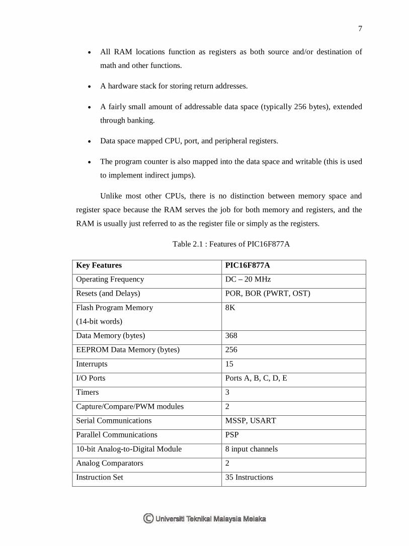
Table 2.1 : Features of PIC16F877A
Key Features PIC16F877A
Operating Frequency DC – 20 MHz
Resets (and Delays) POR, BOR (PWRT, OST)
Flash Program Memory
(14-bit words)
8K
Data Memory (bytes) 368
EEPROM Data Memory (bytes) 256
Interrupts 15
I/O Ports Ports A, B, C, D, E
Timers 3
Capture/Compare/PWM modules 2
Serial Communications MSSP, USART
Parallel Communications PSP
10-bit Analog-to-Digital Module 8 input channels
Analog Comparators 2
Instruction Set 35 Instructions

8
Packages 40-pin PDIP 44-pin PLCC 44-pin TQFP 44-pin QFN
The microcontroller used in this project is the Microchip PIC16F877A. This
controller has 33 inputs and outputs. The input and output for the microcontroller can be
used in any combination. All input and output are connected to the outside world
through the registers which are called port. For this microcontroller, it has 5 ports which
are PORTA, PORTB, PORTC, PORTD and PORTE. PORTA has 6 bits, PORTB
PORTC and PORTD has 8 bits. But PORTE has 3 bits. This project has 2 circuits. The
Master Board circuits uses PORTA, PORTB and PORTC only as the input and output
ports.
2.2 DC Motor Circuit
This project uses DC motor type. The DC motors are fairly simple to
understand. They are also simple to construct and only requires a battery or dc supply to
make them function successfully.
In any electric motor, operation is based on simple electromagnetism. A current-
carrying conductor generates a magnetic field; when this is then placed in an external
magnetic field, it will experience a force proportional to the current in the conductor,
and to the strength of the external magnetic field. The opposite (North and South)
polarities attract, while like polarities (North and North, South and South) repel. The
internal configuration of a DC motor is designed to harness the magnetic interaction
between a current-carrying conductor and an external magnetic field to generate
rotational motion.