Plastic versus Steel: An Automotive Fuel Tank Case Study Using the ...
84
w w w . a u t o s t e e l . o r g Plastic versus Steel: An Automotive Fuel Tank Case Study Using the 2013 GM Cadillac ATS Platform Eric Neuwirth Spectra Premium Industries
-
Upload
trannguyet -
Category
Documents
-
view
220 -
download
1
Transcript of Plastic versus Steel: An Automotive Fuel Tank Case Study Using the ...

w w w . a u t o s t e e l . o r g
Plastic versus Steel:
An Automotive Fuel Tank Case Study
Using the 2013 GM Cadillac ATS Platform
Eric Neuwirth
Spectra Premium Industries

w w w . a u t o s t e e l . o r g
Outline
• Case Study Review ― Design Requirements ― Design Overview ― Forming Analysis ― Manufacturability ― Fuel Capacity / Grade Venting Studies ― Mass ― Pressure / Vacuum Cyclic Fatigue
• Summary ― Conclusions ― Additional Opportunities

w w w . a u t o s t e e l . o r g
Design Requirements
• Atmospheric (non-pressurized) system
• Steel fuel tank requirements
― must fit existing 2013 Cadillac ATS package space, while maintaining appropriate clearances
― must be formable using commercially available steel grades
― must be manufacturable using standard equipment
― must meet or exceed fuel volume of existing plastic fuel tank
― must have a mass that is equivalent to or less than the mass of existing plastic fuel tank
― must meet applicable fuel tank pressure/vacuum cycling durability requirements for an atmospheric system:
― 12,000 PV cycles + 50% safety factor
o Pressure: 14.9 kPa
o Vacuum: 7.0 kPa

w w w . a u t o s t e e l . o r g
Design Requirements
• Based on the design assumptions listed on the previous slide, two
different steel tanks have been designed:
– Volume-Maximizing Steel Tank
o Seeks to maximize usable fuel volume to a level greater than that of
the plastic fuel tank while still maintaining a mass less than that of
the plastic fuel tank
– Volume-Equivalent Steel Tank
o Seeks to achieve a usable fuel volume equal to that of the plastic
fuel tank while achieving a mass significantly less than that of the
plastic fuel tank

w w w . a u t o s t e e l . o r g
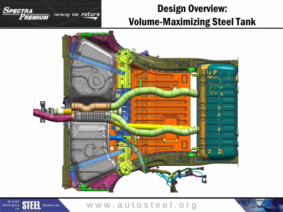
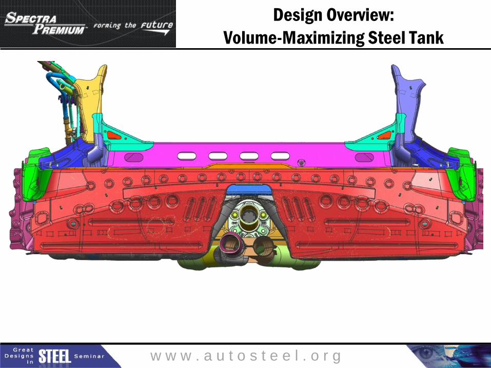
Design Requirements
Steel fuel tank must fit existing
2013 Cadillac ATS package space,
while maintaining appropriate clearances.
w w w . a u t o s t e e l . o r g
Design Overview:
Volume-Maximizing Steel Tank
w w w . a u t o s t e e l . o r g
Design Overview:
Volume-Maximizing Steel Tank

w w w . a u t o s t e e l . o r g
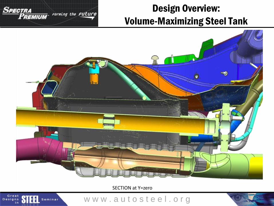
Design Overview:
Volume-Maximizing Steel Tank
w w w . a u t o s t e e l . o r g
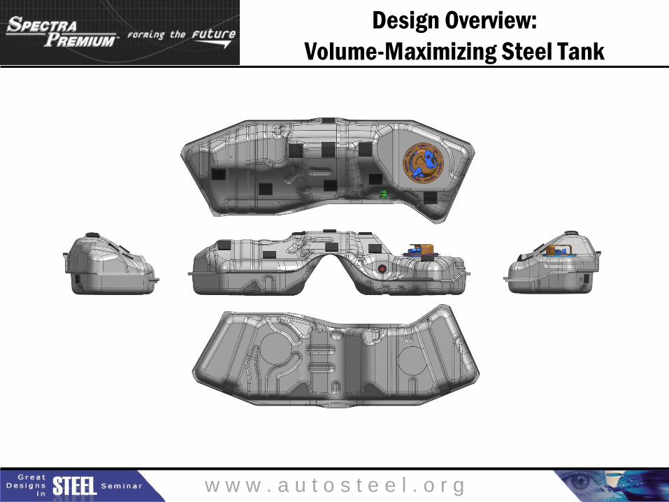
Design Overview:
Volume-Maximizing Steel Tank
SECTION at Y=zero
w w w . a u t o s t e e l . o r g
Design Overview:
Volume-Maximizing Steel Tank

w w w . a u t o s t e e l . o r g
Design Overview:
Volume-Maximizing Steel Tank

w w w . a u t o s t e e l . o r g
Design Overview:
Volume-Maximizing Steel Tank

w w w . a u t o s t e e l . o r g
Design Overview:
Volume-Equivalent Steel Tank
w w w . a u t o s t e e l . o r g
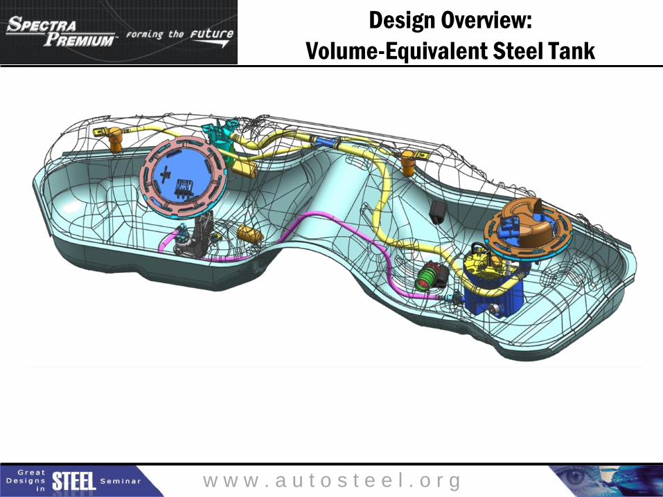
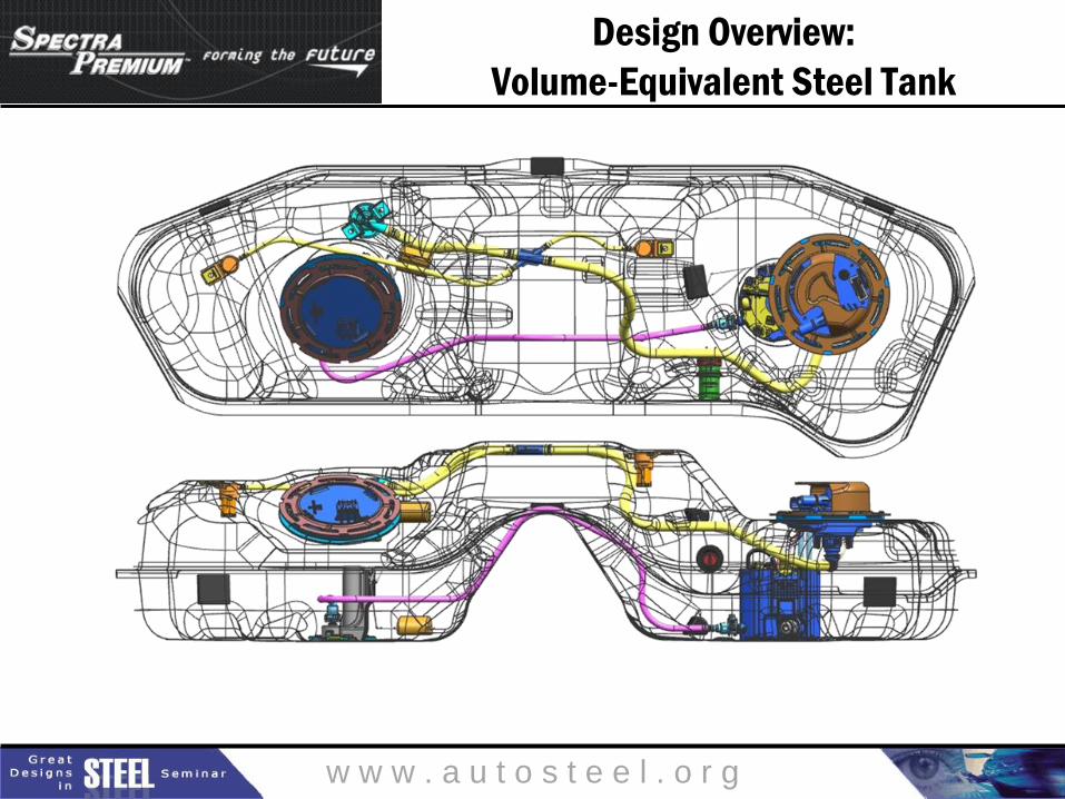
Design Overview:
Volume-Equivalent Steel Tank
w w w . a u t o s t e e l . o r g
Design Overview:
Volume-Equivalent Steel Tank

w w w . a u t o s t e e l . o r g
Design Overview:
Volume-Equivalent Steel Tank
INTERNAL VAPOR MANAGEMENT STEEL : GREEN PLASTIC : PURPLE

w w w . a u t o s t e e l . o r g
Forming Analysis
Steel fuel tank must be formable
using commercially available steel grades.

w w w . a u t o s t e e l . o r g
Forming Analysis
Volume-Maximizing Steel Tank
w w w . a u t o s t e e l . o r g
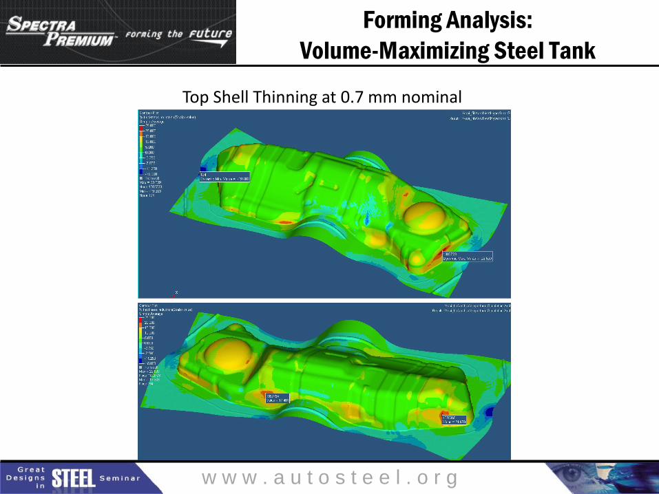
Forming Analysis:
Volume-Maximizing Steel Tank
Top Shell Thinning at 0.7 mm nominal
w w w . a u t o s t e e l . o r g
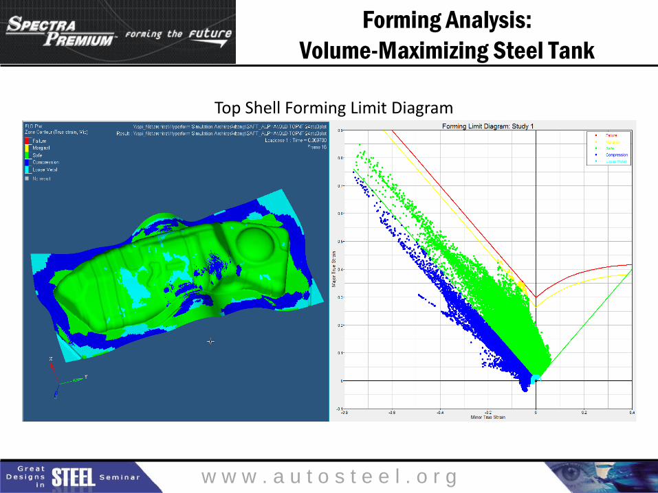
Forming Analysis:
Volume-Maximizing Steel Tank
Top Shell Forming Limit Diagram

w w w . a u t o s t e e l . o r g
Forming Analysis:
Volume-Maximizing Steel Tank
Bottom Shell Thinning at 0.65 mm nominal

w w w . a u t o s t e e l . o r g
Forming Analysis:
Volume-Maximizing Steel Tank
Bottom Shell Forming Limit Diagram

w w w . a u t o s t e e l . o r g
Forming Analysis
Volume-Equivalent Steel Tank
w w w . a u t o s t e e l . o r g
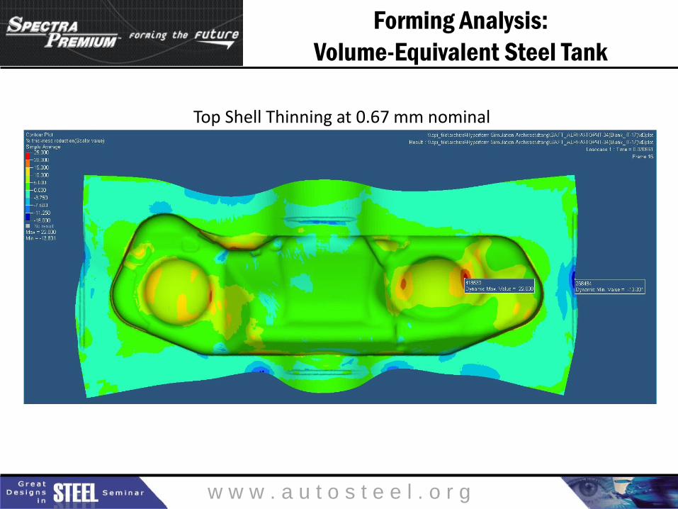
Forming Analysis:
Volume-Equivalent Steel Tank
Top Shell Thinning at 0.67 mm nominal
w w w . a u t o s t e e l . o r g
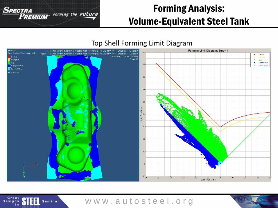
Forming Analysis:
Volume-Equivalent Steel Tank
Top Shell Forming Limit Diagram
w w w . a u t o s t e e l . o r g
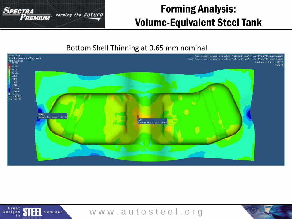
Forming Analysis:
Volume-Equivalent Steel Tank
Bottom Shell Thinning at 0.65 mm nominal

w w w . a u t o s t e e l . o r g
Forming Analysis:
Volume-Equivalent Steel Tank
Bottom Shell Forming Limit Diagram

w w w . a u t o s t e e l . o r g
Manufacturability
Steel fuel tank must be manufacturable
using standard equipment.

w w w . a u t o s t e e l . o r g
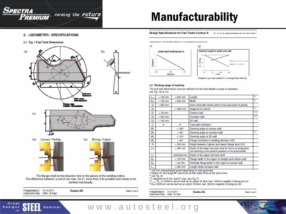
Manufacturability
The following slide shows the relevant Contour II design guidelines, as published by welding
equipment manufacturer Soutec.
Both the Volume-Maximizing tank and the
Volume-Equivalent tank adhere to these guidelines.
w w w . a u t o s t e e l . o r g
Manufacturability

w w w . a u t o s t e e l . o r g
Manufacturability
Andritz Soutec AG Contour II
Fuel Tank Welding Machine
w w w . a u t o s t e e l . o r g
Fuel Capacity / Grade Venting Studies
Steel fuel tank must meet or exceed
fuel volume of existing plastic fuel tank.

w w w . a u t o s t e e l . o r g
Fuel Capacity / Grade Venting Studies
Grade Venting Requirements
When filled to capacity, the fuel tank assembly must be capable of
venting when the vehicle is inclined up to 30% in the four primary
orientations, and up to 27% in the four secondary orientations,
accounting for thermal expansion of the fuel. The fuel tank capacity
used shall be the “Customer Fill Fuel Capacity” plus an additional
4% for fuel expansion for grades less than or equal to 6%, and 2.2%
for fuel expansion for grades greater than 6% up to 30%.
The fuel tank assembly shall be designed to address either a failed
FLVV or GVV with the vehicle on these grades.

w w w . a u t o s t e e l . o r g
Fuel Capacity / Grade Venting Studies
Volume-Maximizing Steel Tank

w w w . a u t o s t e e l . o r g
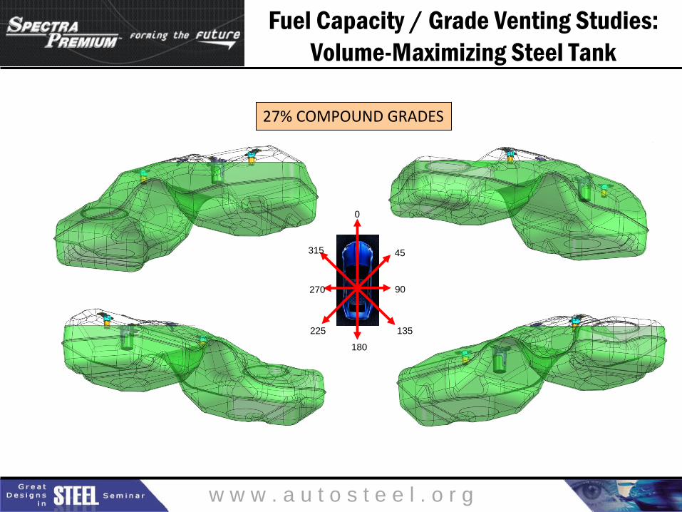
Fuel Capacity / Grade Venting Studies:
Volume-Maximizing Steel Tank
30% STANDARD GRADES
FRONT UP REAR UP
RIGHT SIDE UP LEFT SIDE UP
w w w . a u t o s t e e l . o r g
Fuel Capacity / Grade Venting Studies:
Volume-Maximizing Steel Tank
0
180
45
90
135
315
270
225
27% COMPOUND GRADES
w w w . a u t o s t e e l . o r g
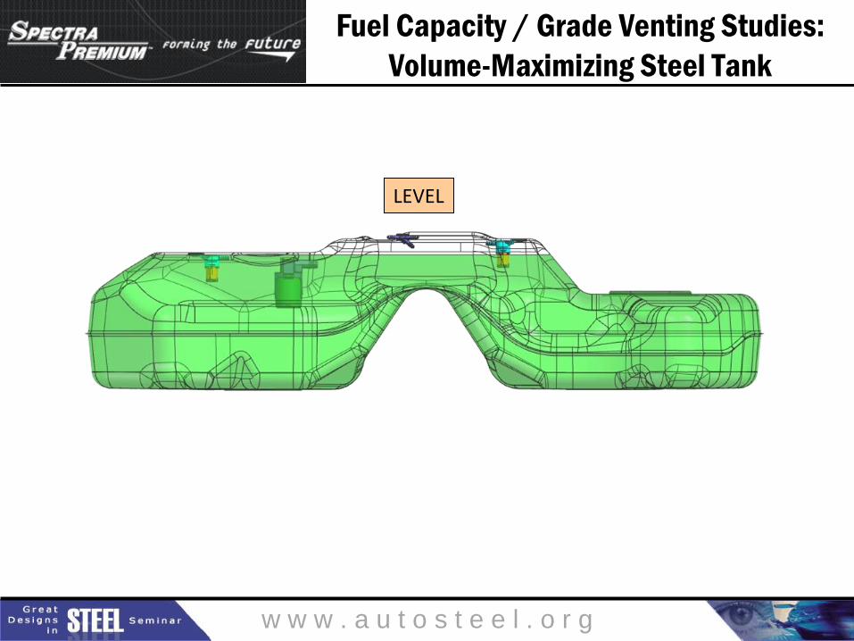
Fuel Capacity / Grade Venting Studies:
Volume-Maximizing Steel Tank
LEVEL
w w w . a u t o s t e e l . o r g
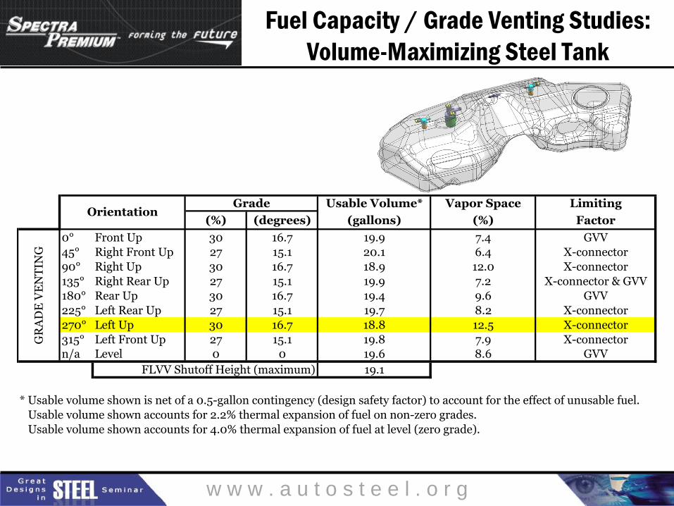
Fuel Capacity / Grade Venting Studies:
Volume-Maximizing Steel Tank
Usable Volume* Vapor Space Limiting
(%) (degrees) (gallons) (%) Factor
0° Front Up 30 16.7 19.9 7.4 GVV
45° Right Front Up 27 15.1 20.1 6.4 X-connector
90° Right Up 30 16.7 18.9 12.0 X-connector
135° Right Rear Up 27 15.1 19.9 7.2 X-connector & GVV
180° Rear Up 30 16.7 19.4 9.6 GVV
225° Left Rear Up 27 15.1 19.7 8.2 X-connector
270° Left Up 30 16.7 18.8 12.5 X-connector
315° Left Front Up 27 15.1 19.8 7.9 X-connector
n/a Level 0 0 19.6 8.6 GVV
FLVV Shutoff Height (maximum) 19.1
* Usable volume shown is net of a 0.5-gallon contingency (design safety factor) to account for the effect of unusable fuel.
Usable volume shown accounts for 2.2% thermal expansion of fuel on non-zero grades.
Usable volume shown accounts for 4.0% thermal expansion of fuel at level (zero grade).
GradeOrientation
GR
AD
E V
EN
TIN
G
w w w . a u t o s t e e l . o r g
Fuel Capacity / Grade Venting Studies:
Volume-Maximizing Steel Tank
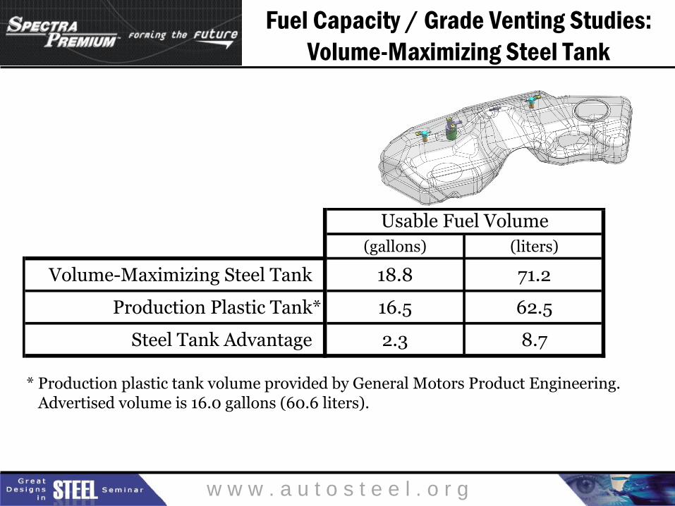
(gallons) (liters)
Volume-Maximizing Steel Tank 18.8 71.2
Production Plastic Tank* 16.5 62.5
Steel Tank Advantage 2.3 8.7
* Production plastic tank volume provided by General Motors Product Engineering. Advertised volume is 16.0 gallons (60.6 liters).
Usable Fuel Volume
w w w . a u t o s t e e l . o r g
Fuel Capacity / Grade Venting Studies:
Volume-Maximizing Steel Tank
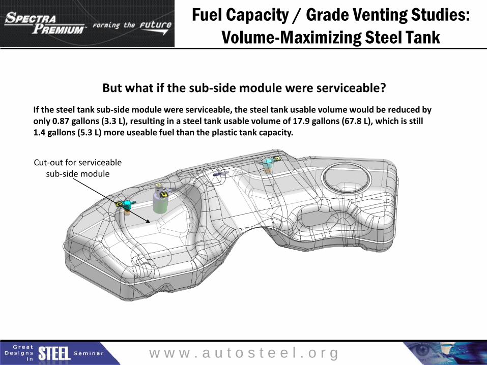
Cut-out for serviceable sub-side module
But what if the sub-side module were serviceable?
If the steel tank sub-side module were serviceable, the steel tank usable volume would be reduced by only 0.87 gallons (3.3 L), resulting in a steel tank usable volume of 17.9 gallons (67.8 L), which is still 1.4 gallons (5.3 L) more useable fuel than the plastic tank capacity.
w w w . a u t o s t e e l . o r g
Fuel Capacity / Grade Venting Studies
Volume-Equivalent Steel Tank

w w w . a u t o s t e e l . o r g
Fuel Capacity / Grade Venting Studies:
Volume-Equivalent Steel Tank
30% STANDARD GRADES FRONT UP REAR UP
RIGHT SIDE UP LEFT SIDE UP
w w w . a u t o s t e e l . o r g
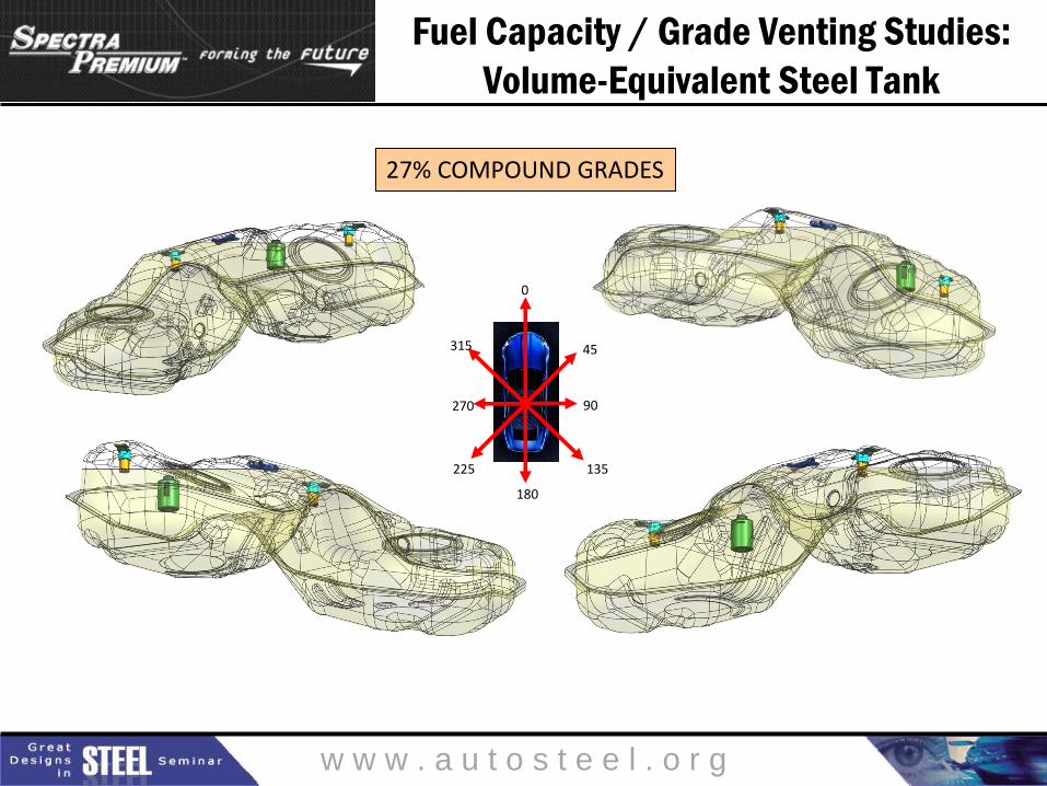
Fuel Capacity / Grade Venting Studies:
Volume-Equivalent Steel Tank
0
180
45
90
135
315
270
225
27% COMPOUND GRADES

w w w . a u t o s t e e l . o r g
Fuel Capacity / Grade Venting Studies:
Volume-Equivalent Steel Tank
LEVEL

w w w . a u t o s t e e l . o r g
Fuel Capacity / Grade Venting Studies:
Volume-Equivalent Steel Tank
Usable Volume* Vapor Space Limiting
(%) (degrees) (gallons) (%) Factor
0° Front Up 30 16.7 17.5 8.0 GVV
45° Right Front Up 27 15.1 17.8 6.8 X-connector
90° Right Up 30 16.7 16.6 12.9 X-connector
135° Right Rear Up 27 15.1 17.5 8.0 X-connector & GVV
180° Rear Up 30 16.7 17.3 8.9 GVV
225° Left Rear Up 27 15.1 17.5 8.4 X-connector
270° Left Up 30 16.7 16.5 13.7 X-connector
315° Left Front Up 27 15.1 17.5 8.2 X-connector
n/a Level 0 0 17.4 8.9 GVV
FLVV Shutoff Height (maximum) 16.5
* Usable volume shown is net of a 0.5-gallon contingency (design safety factor) to account for the effect of unusable fuel.
Usable volume shown accounts for 2.2% thermal expansion of fuel on non-zero grades.
Usable volume shown accounts for 4.0% thermal expansion of fuel at level (zero grade).
GradeOrientation
GR
AD
E V
EN
TIN
G

w w w . a u t o s t e e l . o r g
Mass
Steel fuel tank must have
a mass that is equivalent to or less than
the mass of existing plastic fuel tank.
w w w . a u t o s t e e l . o r g
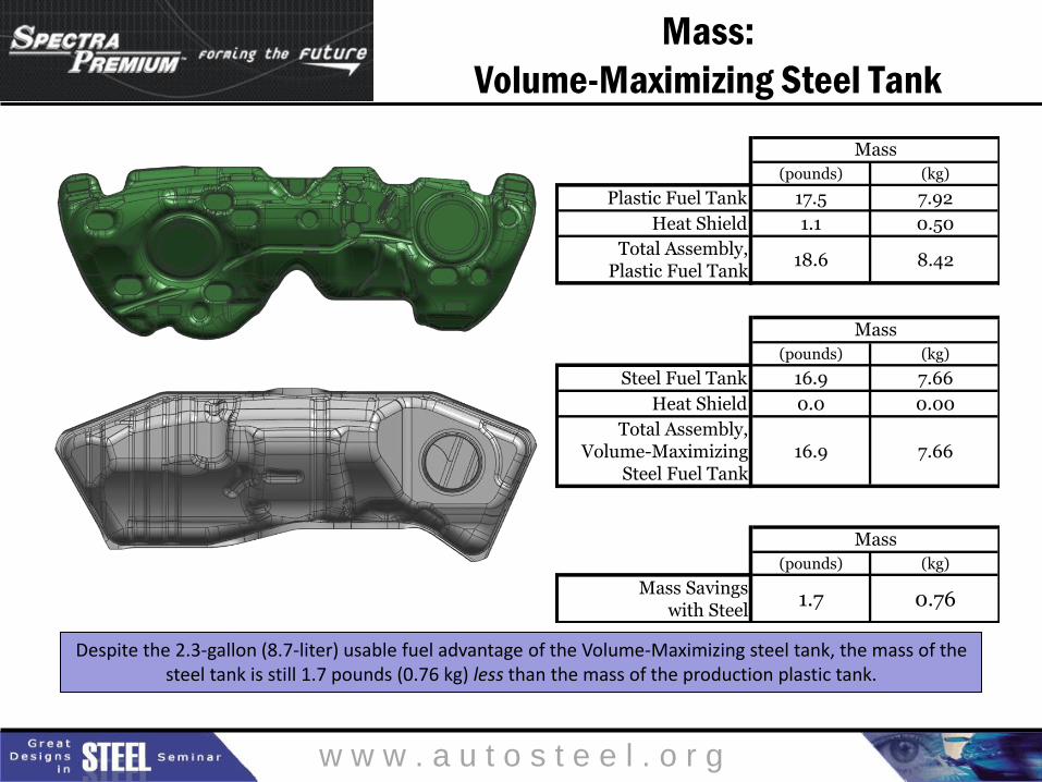
Mass:
Volume-Maximizing Steel Tank
(pounds) (kg)
Plastic Fuel Tank 17.5 7.92
Heat Shield 1.1 0.50
Total Assembly,Plastic Fuel Tank
18.6 8.42
(pounds) (kg)
Steel Fuel Tank 16.9 7.66
Heat Shield 0.0 0.00
Total Assembly,Volume-Maximizing
Steel Fuel Tank16.9 7.66
(pounds) (kg)
Mass Savingswith Steel
1.7 0.76
Mass
Mass
Mass
Despite the 2.3-gallon (8.7-liter) usable fuel advantage of the Volume-Maximizing steel tank, the mass of the steel tank is still 1.7 pounds (0.76 kg) less than the mass of the production plastic tank.
w w w . a u t o s t e e l . o r g
Mass:
Volume-Maximizing Steel Tank
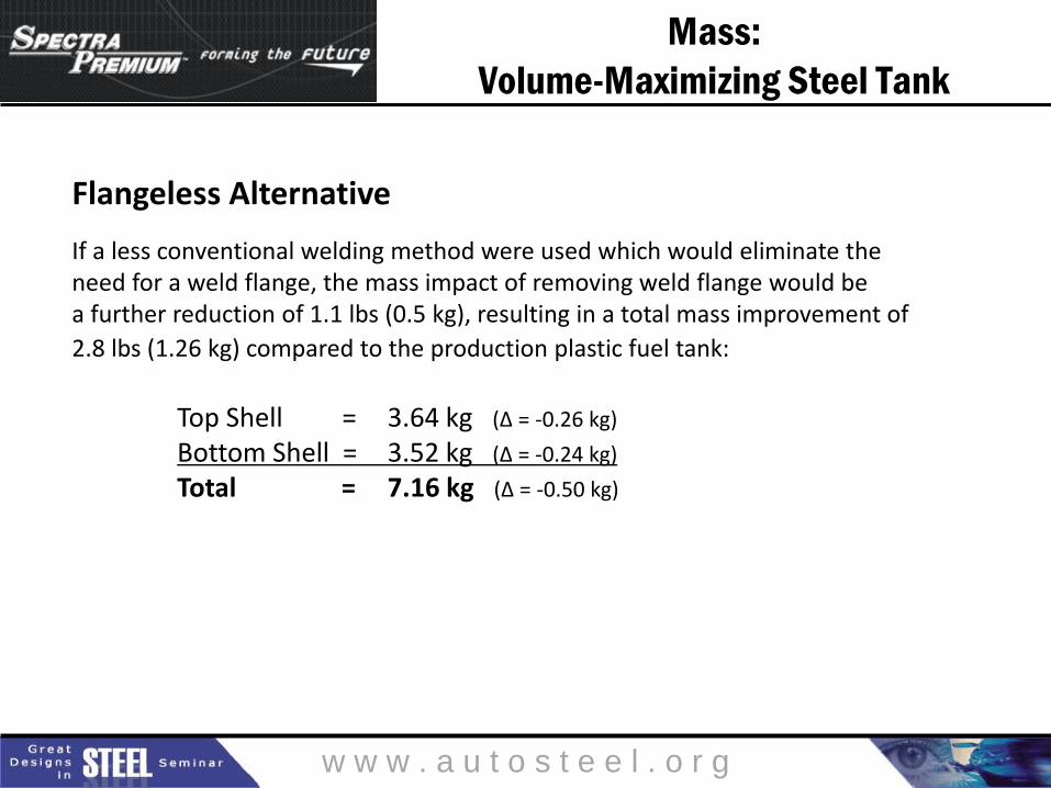
Flangeless Alternative
If a less conventional welding method were used which would eliminate the need for a weld flange, the mass impact of removing weld flange would be a further reduction of 1.1 lbs (0.5 kg), resulting in a total mass improvement of
2.8 lbs (1.26 kg) compared to the production plastic fuel tank: Top Shell = 3.64 kg (Δ = -0.26 kg)
Bottom Shell = 3.52 kg (Δ = -0.24 kg)
Total = 7.16 kg (Δ = -0.50 kg)

w w w . a u t o s t e e l . o r g
Mass:
Volume-Equivalent Steel Tank
(pounds) (kg)
Plastic Fuel Tank 17.5 7.92
Heat Shield 1.1 0.50
Total Assembly,Plastic Fuel Tank
18.6 8.42
(pounds) (kg)
Steel Fuel Tank 15.5 7.03
Heat Shield 0.0 0.00
Total Assembly,Volume-Maximizing
Steel Fuel Tank15.5 7.03
(pounds) (kg)
Mass Savingswith Steel
3.1 1.39
Mass
Mass
Mass
In the case of the Volume-Equivalent steel tank, the mass benefit is even greater. This fully functional design saves 3.1 pounds (1.39 kg) compared to the production plastic tank.
w w w . a u t o s t e e l . o r g
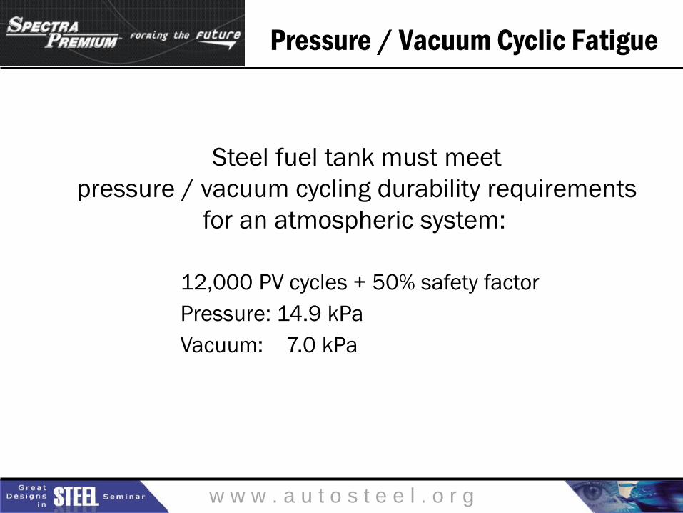
Pressure / Vacuum Cyclic Fatigue
Steel fuel tank must meet
pressure / vacuum cycling durability requirements
for an atmospheric system:
12,000 PV cycles + 50% safety factor
Pressure: 14.9 kPa
Vacuum: 7.0 kPa

w w w . a u t o s t e e l . o r g
Pressure / Vacuum Cyclic Fatigue
Volume-Maximizing Steel Tank

w w w . a u t o s t e e l . o r g
Pressure / Vacuum Cyclic Fatigue:
Volume-Maximizing Steel Tank

w w w . a u t o s t e e l . o r g
Pressure / Vacuum Cyclic Fatigue:
Volume-Maximizing Steel Tank
Loading Details
Load Optistruct Equation Location
Hydro 7.23213e-6*(898-z) All elements below Z height of 898 mm
Positive Pressure 14.9 kPa All internal elements
Negative Pressure 7 kPa All internal elements
Pre-load Z=3 mm Strap ends
w w w . a u t o s t e e l . o r g
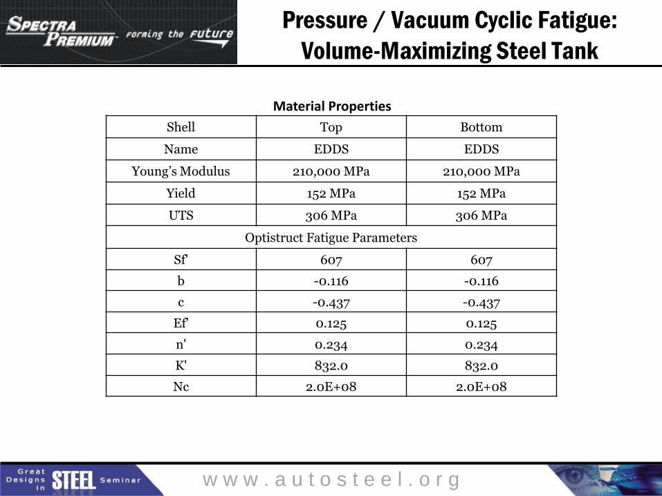
Pressure / Vacuum Cyclic Fatigue:
Volume-Maximizing Steel Tank
Material Properties
Shell Top Bottom
Name EDDS EDDS
Young’s Modulus 210,000 MPa 210,000 MPa
Yield 152 MPa 152 MPa
UTS 306 MPa 306 MPa
Optistruct Fatigue Parameters
Sf' 607 607
b -0.116 -0.116
c -0.437 -0.437
Ef' 0.125 0.125
n' 0.234 0.234
K' 832.0 832.0
Nc 2.0E+08 2.0E+08

w w w . a u t o s t e e l . o r g
Pressure / Vacuum Cyclic Fatigue:
Volume-Maximizing Steel Tank
Shell Fatigue Life
(cycles)
Top 17,975
Bottom 19,382

w w w . a u t o s t e e l . o r g
Pressure / Vacuum Cyclic Fatigue:
Volume-Maximizing Steel Tank
Fatigue - Top

w w w . a u t o s t e e l . o r g
Pressure / Vacuum Cyclic Fatigue:
Volume-Maximizing Steel Tank
Fatigue - Top

w w w . a u t o s t e e l . o r g
Pressure / Vacuum Cyclic Fatigue:
Volume-Maximizing Steel Tank
Fatigue - Bottom

w w w . a u t o s t e e l . o r g
Pressure / Vacuum Cyclic Fatigue:
Volume-Maximizing Steel Tank
Fatigue - Bottom

w w w . a u t o s t e e l . o r g
Pressure / Vacuum Cyclic Fatigue:
Volume-Maximizing Steel Tank
Displacement (+14.9 kPa)

w w w . a u t o s t e e l . o r g
Pressure / Vacuum Cyclic Fatigue:
Volume-Maximizing Steel Tank
Displacement (-7 kPa)
w w w . a u t o s t e e l . o r g
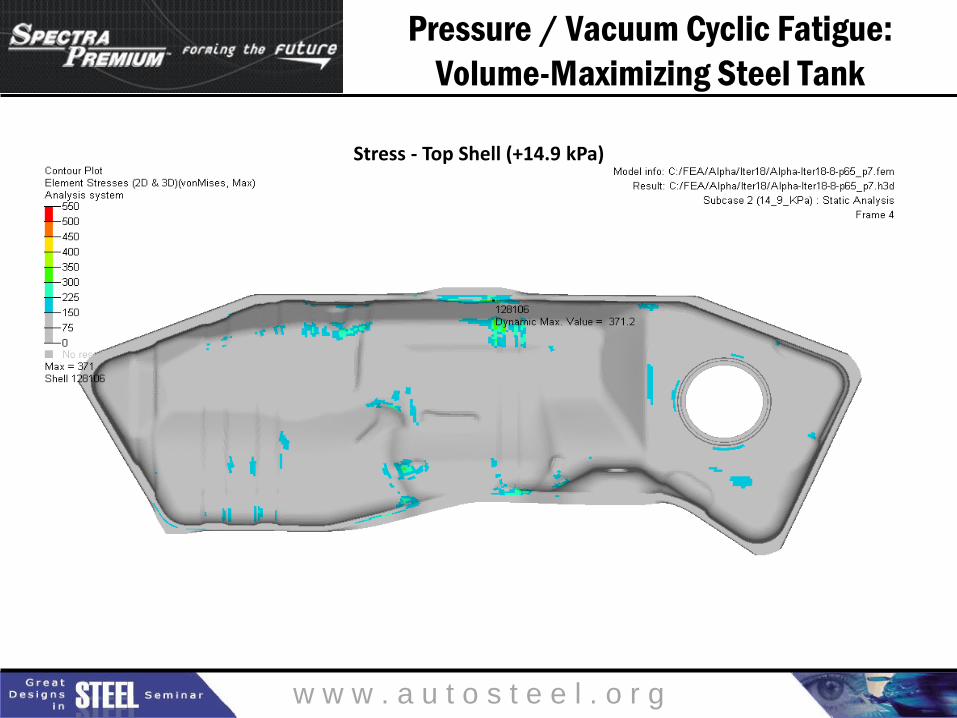
Pressure / Vacuum Cyclic Fatigue:
Volume-Maximizing Steel Tank
Stress - Top Shell (+14.9 kPa)
w w w . a u t o s t e e l . o r g
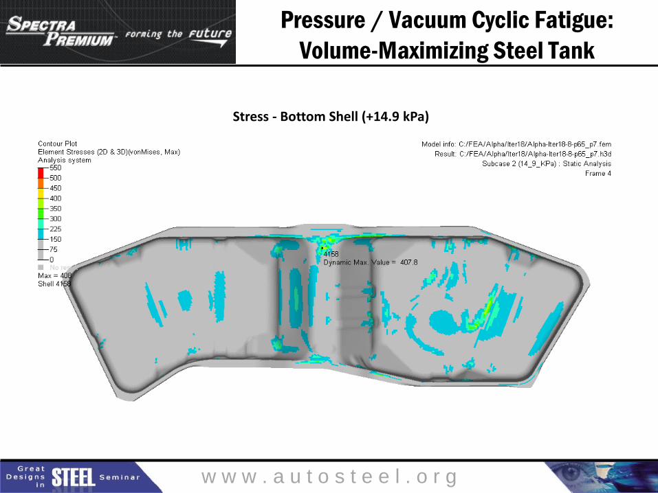
Pressure / Vacuum Cyclic Fatigue:
Volume-Maximizing Steel Tank
Stress - Bottom Shell (+14.9 kPa)

w w w . a u t o s t e e l . o r g
Pressure / Vacuum Cyclic Fatigue:
Volume-Maximizing Steel Tank
Stress - Top Shell (-7 kPa)
w w w . a u t o s t e e l . o r g
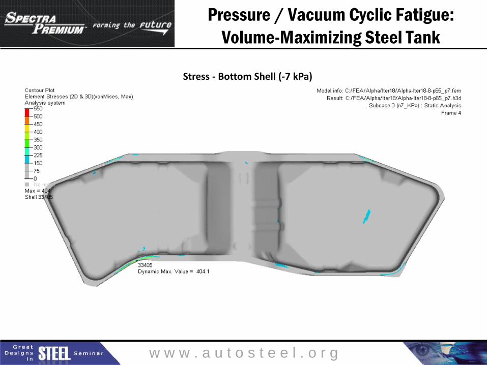
Pressure / Vacuum Cyclic Fatigue:
Volume-Maximizing Steel Tank
Stress - Bottom Shell (-7 kPa)

w w w . a u t o s t e e l . o r g
Pressure / Vacuum Cyclic Fatigue
Volume-Equivalent Steel Tank
w w w . a u t o s t e e l . o r g
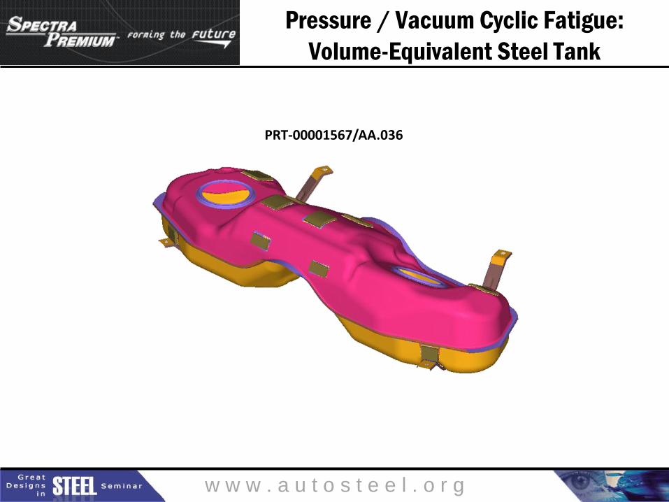
Pressure / Vacuum Cyclic Fatigue:
Volume-Equivalent Steel Tank
PRT-00001567/AA.036
w w w . a u t o s t e e l . o r g
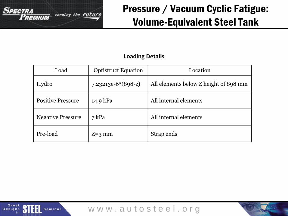
Pressure / Vacuum Cyclic Fatigue:
Volume-Equivalent Steel Tank
Loading Details
Load Optistruct Equation Location
Hydro 7.23213e-6*(898-z) All elements below Z height of 898 mm
Positive Pressure 14.9 kPa All internal elements
Negative Pressure 7 kPa All internal elements
Pre-load Z=3 mm Strap ends

w w w . a u t o s t e e l . o r g
Pressure / Vacuum Cyclic Fatigue:
Volume-Equivalent Steel Tank
Shell Top Bottom
Name EDDS EDDS
Young’s Modulus 210 000 MPa 210 000 MPa
Yield 150 MPa 150 MPa
UTS 270 MPa 270 MPa
Optistruct Fatigue Parameters
Sf' 405 405
b -0.087 -0.087
c -0.58 -0.58
Ef' 0.59 0.59
n' 0.15 0.15
K' 445 445
Nc 2.0E+08 2.0E+08
Material Properties
w w w . a u t o s t e e l . o r g
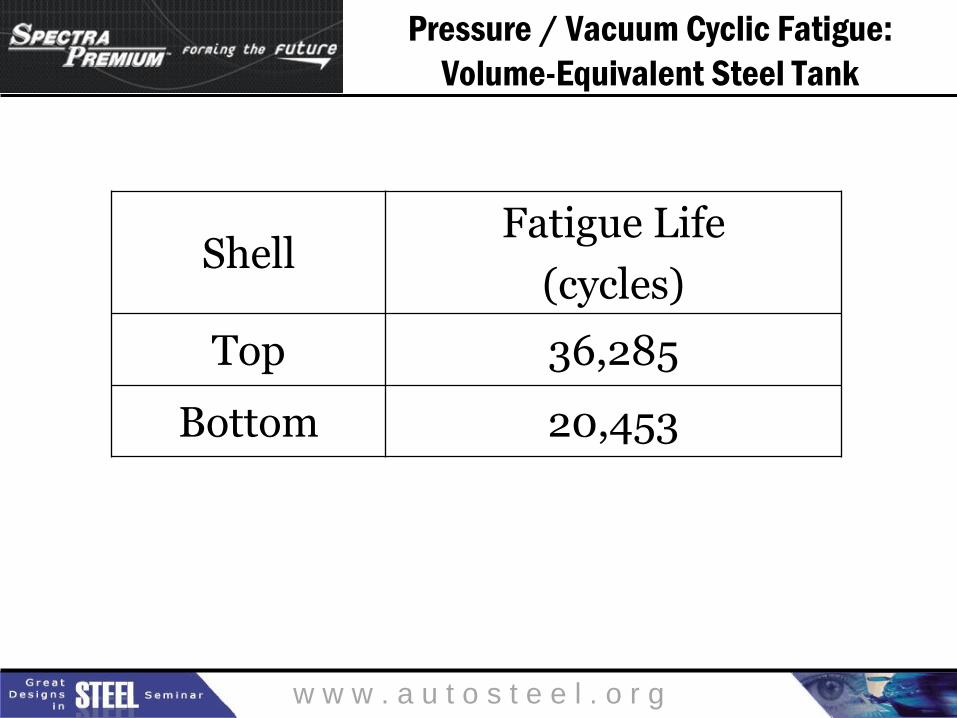
Pressure / Vacuum Cyclic Fatigue:
Volume-Equivalent Steel Tank
Shell Fatigue Life
(cycles)
Top 36,285
Bottom 20,453
w w w . a u t o s t e e l . o r g
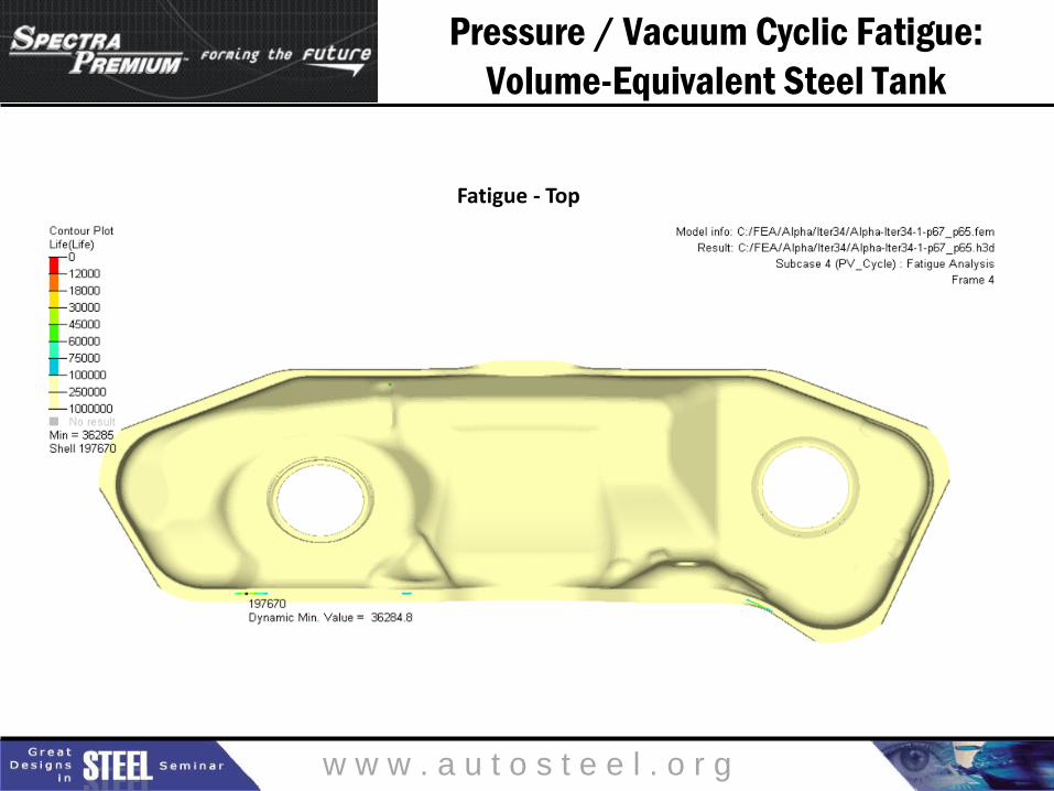
Pressure / Vacuum Cyclic Fatigue:
Volume-Equivalent Steel Tank
Fatigue - Top

w w w . a u t o s t e e l . o r g
Pressure / Vacuum Cyclic Fatigue:
Volume-Equivalent Steel Tank
Fatigue - Top

w w w . a u t o s t e e l . o r g
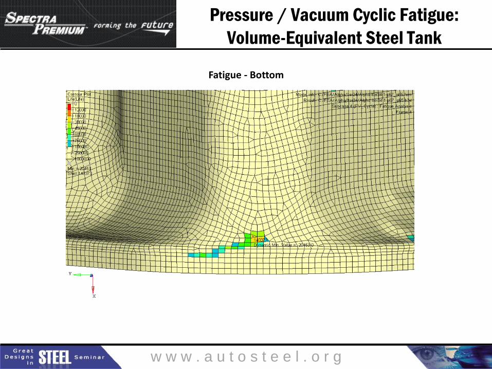
Pressure / Vacuum Cyclic Fatigue:
Volume-Equivalent Steel Tank
Fatigue - Bottom
w w w . a u t o s t e e l . o r g
Pressure / Vacuum Cyclic Fatigue:
Volume-Equivalent Steel Tank
Fatigue - Bottom

w w w . a u t o s t e e l . o r g
Pressure / Vacuum Cyclic Fatigue:
Volume-Equivalent Steel Tank
Displacement (+14.9 kPa)
w w w . a u t o s t e e l . o r g
Pressure / Vacuum Cyclic Fatigue:
Volume-Equivalent Steel Tank
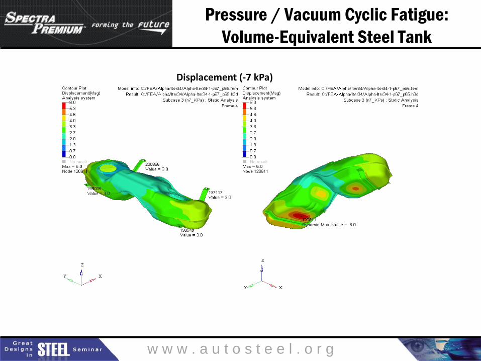
Displacement (-7 kPa)
w w w . a u t o s t e e l . o r g
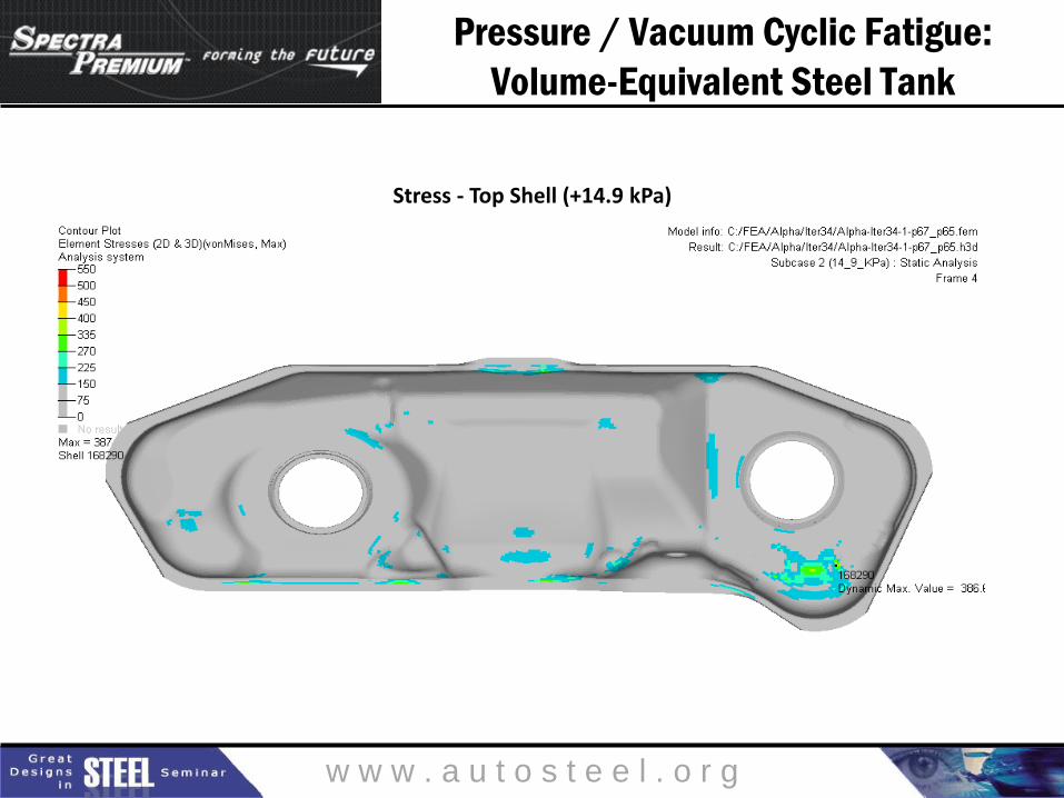
Pressure / Vacuum Cyclic Fatigue:
Volume-Equivalent Steel Tank
Stress - Top Shell (+14.9 kPa)

w w w . a u t o s t e e l . o r g
Pressure / Vacuum Cyclic Fatigue:
Volume-Equivalent Steel Tank
Stress - Bottom Shell (+14.9 kPa)

w w w . a u t o s t e e l . o r g
Pressure / Vacuum Cyclic Fatigue:
Volume-Equivalent Steel Tank
Stress - Top Shell (-7 kPa)

w w w . a u t o s t e e l . o r g
Pressure / Vacuum Cyclic Fatigue:
Volume-Equivalent Steel Tank
Stress - Bottom Shell (-7 kPa)

w w w . a u t o s t e e l . o r g
Summary: Conclusions
• Two different steel fuel tanks – a volume-maximizing tank and a volume-equivalent tank – have been designed to fit the existing 2013 Cadillac ATS package space, while maintaining appropriate clearances.
• These steel fuel tanks
– are both formable using commercially available steel grades.
– are both manufacturable using standard equipment.
– have a usable fuel volume that exceeds the usable fuel volume of the existing plastic fuel tank by up to 8.7 L (2.3 gallons).
– are as much as 1.39 kg (3.06 lbs) lighter than the existing plastic fuel tank, not including the additional mass avoidance with the flangeless alternative.
– both meet the fuel tank pressure / vacuum cycling durability requirements specified for an atmospheric system, including a 50% safety factor.

w w w . a u t o s t e e l . o r g
Summary: Additional Opportunities
• The results presented here are a work-in-progress. It is possible to
continue to improve the 2013 Cadillac ATS steel fuel tank designs with the
following goals:
– Achieve nominal gauge of 0.6 mm through further topography
optimization.
– Design slosh baffles that are also structural, thereby allowing a
further reduction in shell gauge.
– Further reduce mass through the use of alternative steels such as
advanced high strength steels or stainless steels.
w w w . a u t o s t e e l . o r g
For More Information
Visit: www.autosteel.org
@SMDISteel
www.facebook.com/SMDISteel Rich Cover Program Manager, SASFT +1 (248) 762-7732 [email protected] Eric Neuwirth Spectra Premium Industries
+1 (248) 207-5509

w w w . a u t o s t e e l . o r g
Great Designs in Steel is Sponsored by:
Use your web-enabled device to download the presentations from today’s event
PRESENTATIONS WILL BE AVAILABLE MAY 3