PLASTIC R SERIES CONNECTORS SERIES - LEMO Series Production Program .....4 Series and Contact...
31
PLASTIC R SERIES CONNECTORS SERIES
Transcript of PLASTIC R SERIES CONNECTORS SERIES - LEMO Series Production Program .....4 Series and Contact...

PLASTIC R SERIESCONNECTORS SERIES

1www.lemo.com
® ®
Table of Contents
General Production Program. .............................................................................................................page 2Main Characteristics and Types...................................................................................................................2Series and Types ..........................................................................................................................................3LEMO's Push-Pull Self-Latching Connection System ................................................................................4R Series Production Program ......................................................................................................................4Series and Contact configuration ................................................................................................................4
R Series Section......................................... .....................................................................................................................................................................5Interconnections ...........................................................................................................................................6Model Description ........................................................................................................................................6Part Number Example ..................................................................................................................................7Part Selection Showing Internal Components ............................................................................................7Housing Models ........................................................................................................................................8-9Alignment Key and Polarized Keying System ...........................................................................................10Crimp Contacts ..........................................................................................................................................11Mixed Hybrid Overview..............................................................................................................................12Inserts Multipole .........................................................................................................................................13Mixed High Voltage + Low Voltage. .....................................................................................................14-15Mixed Coax & Low Voltage ..................................................................................................................16-17Mixed Fluidic & Low Voltage......................................................................................................................18Fluidic/Pnuematic Contacts .................................................................................................................19-20Housing Colors...........................................................................................................................................21
Accessories................................................Insulators for crimp contacts ...............................................................................................................22-23Clamping and Bracketing...........................................................................................................................22Inserts and Crimp contacts........................................................................................................................23
Tooling........................................................Crimping tools.......................................................................................................................................24-25Positioners for crimp contact.....................................................................................................................24Extractor for crimp contact ........................................................................................................................25
Panel Cut-Outs..........................................Mounting.....................................................................................................................................................26
PCB Drilling Pattern...................................Fixed receptacle with straight print contacts............................................................................................26
Technical Characteristics...........................Outer Shell..................................................................................................................................................27Insulator......................................................................................................................................................27Electrical contact........................................................................................................................................28Crimp contacts ...........................................................................................................................................29

www.lemo.com2
® ®
Patch Panels For fiber optic applications
Adapters For BNC, C, UHF, N, CINCH, GEN-RADIO connectors For TNC, SMA connectors
Accessories � Insulator for crimp contacts � Crimp contacts � Coaxial contacts Triaxial contacts � Fiber optic contacts � Fiber optic ferrules Caps Bend relief Heatshrink boot Insulating washers Double plastic panel washers Locking washers Tapered washers Hexagonal nuts Conical nuts Round nuts Notched nuts Earthing washers Lead-through with cable collet
Tooling Wrenches Assembly tool Pliers Taps � Crimping tools � Positioners Crimping dies � Extractors Banding tool Retention testing tool for crimp contacts Fiber optic termination workstation Fiber optic polishing tools
On request Filtered connectors Connectors with special housing Mixed special configuration Assembly onto cable
� Connectors, accessories and tools found in this catalog.
General Production ProgramConnectors Unipole from 2 to 150 Amps Coaxial 50 and 75 Ω Coaxial 50 Ω (NIM-CAMAC) Coaxial 50 Ω for frequency � 12 GHz Multicoaxial 50 and 75 Ω � Multipole from 2 to 66 contacts Multipole up to 106 contacts High Voltage 3, 5, 8, 10, 15, 30 and 50 kV cc Multi High Voltage 3, 5, and 10 kV cc Triaxial 50 and 75 Ω Quadrax � Mixed: High Voltage (HV) + Low Voltage (LV) � Mixed: Coax + LV Mixed: Triax + LV Thermocouple Multithermocouple Fiber optic singlemode Fiber optic multimode � Mixed: fiber optic + LV Mixed: fiber optic + coax + LV Fluidic Multifluidic � Mixed: fluidic + LV Subminiature Miniature Plastic Printed circuit board Remote handling Watertight Sealed (pressure and/or vacuum) � With plastic outer shell With aluminum outer shell With stainless steel outer shell With special radiation resistant insulator material With screw thread coupling for very high pressure With microswitch
Patch Panels For audio-mono applications: triax For audio-mono applications: 3 contacts For audio-stereo applications: quadrax For audio-stereo applications: 6 contacts For video applications: coax 75 Ω For video HDTV applications: 3 coax 75 Ω + 2LV
STANDARD
01 (Minax)00 (NIM-CAMAC)00 (unipole)05 / R00S to 6S0A / 4A1D / 2C1Y-3Y-6Y
Series
Latching
Key
Shell
Insert
Contact
WATERTIGHT
0E to 6E3T4M
KEYED
00 (multipole)0B to 5B2G / 5G
KEYEDWATERTIGHT
HARSHENVIRONMENTS
0K to 5K2N to 5N
SCREW
030V to 5V0W to 5W2U to 5U0M-1M-2M
Stepped insert (Half-Moon)
Hermaphroditic or cylindrical
Screw
Key (G) or stepped insert (Half-Moon)
Solder(crimp or print)
Hermaphroditic or cylindrical
Key (G)or other key-way code
Key (N) or otherkey-way code
Solder or print Solder, crimp or print Crimp or print
Cylindrical
Metal or plastic Metal or plasticMetal
Push-Pull
Main Characteristics and Types
FF to 5F
Metal Metal
RECTANGULAR
RR / 0R / 1R
Key G or A
Crimp or print
Rectangular
Plastic

3www.lemo.com
® ®
� �
� � � �
� � � �
� �
� � � � �
� � � � � �
� � � � � � � �
� � � � � � � � �
� � � � � � � �
� � � � � �
� � � � � � � �
� � � �
�
030V1V2V3V4V5V
0W to 5W2U to 5U0M to 2M
� � � �
� � �
� � � � � � � �
� � � � � � � � � �
� � � � � � � � � �
� � � � � � �
�
�
0K1K2K3K4K5K
FF to 5F2N to 5N
010005R00A0S1S2S3S4S5S6S1D2C4A
1Y-3Y-6Y
Series
Unipole
Coaxial 50
Ω
Coaxial 75
Ω
Multipole
High Voltage
Triaxial 50
Ω
Triaxial 75
Ω
Quadrax
Multi HV
Multi Coaxial
Mixed HV+LV
Mixed Coax+LV
Mixed Triax+LV
Fiber Optic
Multi FO
Mixed FO+LV
Fluidic
Multi fluidic
Mixed fluidic+LV
Thermocouple
0E1E2E3E4E5E6E3T4M
Types
Standard
Watertight
Keyed
Keyedwatertight
Rectangular
Screw
Series and Types
000B1B2B3B4B5B2G5G
RR0R1R
�
� � � �
�
�
� �
� � � � � �
� � � � � � �
� � � � � � � � �
� � � � � � � � � �
� � � � � � � � � � �
� � � � � � � �
� � �
�
� �
�
�
� � � � � �
� � � � � � �
� � � � � � � � �
� � � � � � � � � �
� � � � � � � �
� � � � � �
� � �
� �
� �
� �
� � � �
� � �
� � � � � � � � �
� � � � � � � � �
� � � � � � � � � �
� � � � � � �
�
�
Note: � = included in this catalog, � = available but not included in this catalog.

www.lemo.com4
® ®
min.Cable ø range (mm) max.
LEMO’s Push-Pull Self-Latching Connection System
The plug and the receptacle can be mated by simply pushing axially the outer shell of the plug.
Pulling on the cable or any other component of the plug than the outer release sleeve cannot break the connection.
The connector can be unmated by a single axial pull on the plug outer release sleeve.
This self-latching system is renowned worldwide for its easy and quick mating and unmating features. It provides absolutesecurity against vibration, shock or pull on the cable, and facilitates operation in a very limited space.
R Series Production Program
Series RR 0R 1R
1.0 1.5 2.0 4.0 6.2 9.2
Number of contacts (multipole)Number of contacts (mixed HV+LV)Number of contacts (mixed coax+LV)Number of contacts (mixed fluidic+LV)
13 10, 17, 37 28, 36, 67 – 4 HV + 4 LV, 2 HV + 13 LV 8 HV + 3 LV 1 coax + 4 LV 4 coax + 4 LV, 2 coax + 13 LV 8 coax + 3 LV – 4 fluidic + 4 LV, 2 fluidic + 13 LV 8 fluidic + 3 LV
Note: «LV» stands for low voltage.

R S
ER
IES

The R series is a rectangular connector with high pin density in a flat profile. It uses LEMO’s well proven Push-Pull latching system for a smooth, hassle free connection. The ergonomic and flat profile offers high panel density, in a widechoice of colors for excellent visual aesthetics.
The R series is made of lightweight polyester resin Crastin® PBT from DupontTM. The high flexibility of its design enablesvarious contact configuration, such as multipole, coaxial, high voltage and fluidic.
R series connectors provide the following main features:
– plastic shell for lightweight yet rugged structure – high pin density for improved panel space– push-pull latching enable fast and secure connections – 3 sizes and various models for design choices– crimp or printed circuit contacts – standard or hybrid pin configurations for flexibility– choice of 4 colors for aesthetics – thin footprint for reduced rack spaceand quick identification and high density panel.
The R series, is initially designed to interconnect systems in medical application where aesthetics and safety is required.This connector series can also be used for test & measurement, aerospace and automotive testing, where an extensivenumber of contacts are needed in a limited space.
Plastic material used for manufacturing insulators is selected according to the required electric and thermal properties.The thermoplastic used is PEEK (Polyether-Etherketone) with the addition of glass fibers to improve mechanical charac-teristics and to increase dielectric strength.
R Series
FGG
EGG PHG
EBG PBG
Straight plug Fixed receptacles Free receptaclesPlastic housing models
www.lemo.com6
® ®

7www.lemo.com
® ®
outer shellhexagonal nutlocking washerscrewinsulatorfemale contact
43
65
12
Fixed receptacle
outer shelllatch sleevescrewinsulatormale contactcable clamping
43
5
12
Straight plug
16543 12 5342
6
6
Straight plug with cable collet:FGG.1R.336.GLC92 = straight plug with key (G) and cable collet, 1R series, multipole type with 36 contacts, outer shell in gray PBT, PEEK insulator, male crimp contacts, collet for 9.2 mm maximum diameter cable.
FG G 1R
Insert configuration: (page 13-18)
336
Series: (page 12)
Model: (page 8-9)
Alignment key: (page 10)
G L C 92
Fixed receptacle EG G 1R 336 G L M
Housing color: (page 21)
Insulator: L = PEEK
Contact: (page 11)
Cable ø: (page 22)
Variant:Cable Group: (page 17)
Fixed receptacle:EGG.1R.336.GLM = fixed receptacle, nut fixing, with key (G), 1R series, multipole type with 36 contacts, outer shell in grayPBT, PEEK insulator, female crimp contacts.
Part Numbering System
Plug
PH G 1R 336 G L M 92Free receptacle
Part Section Showing Internal Components
Part Number Example
Free receptacle:PHG.1R.336.GLM92 = free receptacle with key (G) and cable collet, 1R series, multipole type with 36 contacts, outer shell in gray PBT, PEEK insulator, female crimp contacts, collet for 9.2 mm maximum diameter cable.
. . .
. . .
. . .

www.lemo.com8
® ®
Housing models
FGG Straight plug, key (G) or key (A), with cable collet
Reference
Model Series
FGG RR FGG 0R FGG 1R
18.0 6.0 21.5 17.0 24.5 9.0 30.5 23.5 37.0 12.5 39.0 31.0
Dimensions (mm)
A B L M
EGG Fixed receptacle, key (G) or key (A)with visible shell
Reference
Model Series
EGG RR EGG 0R EGG 1R
M
A
L
B
M
A
L
B
18.0 6.0 12.0 7.0 24.5 9.0 14.0 12.0 37.0 12.5 18.0 14.5
Dimensions (mm)
A B L M
P1 Panel cut-out page 26)
EGG Fixed receptacle, key (G) or key (A) with visible shell and contacts for printed circuit
Reference
Model Series
EGG RR EGG 0R EGG 1R
M
A
L
B
18.0 6.0 12.0 7.0 24.5 9.0 14.0 12.0 37.0 12.5 18.0 14.5
Dimensions (mm)
A B L M
P1 Panel cut-out page 26)

9www.lemo.com
® ®
P2 Panel cut-out page 26
PHG Free receptacle, key (G) or key (A), with cable collet
PBG Fixed receptacle, key (G) or key (A), with flange and cable collet
Reference
Model Series
PHG RR PHG 0R PHG 1R
A
LB
A
EL
C
B
ø G
18.0 6.0 22.3 24.5 9.0 31.5 37.0 12.5 39.0
Dimensions (mm)
A B L
Reference
Model Series
PBG 1R 37.0 15.0 51.0 4.5 3.2 39.0
Dimensions (mm)
A B C E G L
EBG Fixed receptacle, key (G) or key (A), with flange
Reference
Model Series
EBG 1R 37.0 15.0 51.0 4.5 3.2 19.5 14.5
Dimensions (mm)
A B C E G L M
M
A
E
L
C
B
ø G
P2 Panel cut-out page 26
EBG 0R 24.5 10.5 34 3.2 2.2 18.0 12.0
PBG 0R 24.5 10.5 34.5 3.2 2.2 31.5

www.lemo.com10
® ®
α 50° 50° 50° β 30° 30° 30° α 42° 42° 42° γ 30° 30° 30°
Series
RR 0R 1R
Alignment Key and Polarized Keying System
��G
��A
Model Nb of
keys
Angles
Contact type
Plug Receptacle
Note
male female male female male female male female
�
�
�
�
� First choice alternative� Special order alternative
R series connector model part numbers are composed of three letters. The LAST LETTER indicates the key position.
Front view of a receptacle
Alignment Key

11www.lemo.com
® ®
Contacts for plugs, free or fixed receptacles
Ref.
CBGM
Contact type
Male crimp (fig. 1)1)
Male crimp (fig. 2)1)
Male crimp (fig. 2)1)
Female crimp (fig. 1)1)
Ref.
PUN
Contact type
Female crimp (fig. 2)1)
Female crimp (fig. 2)1)
Female straight print
Note: 1) there are two forms of crimp barrels. Please consult adjacenttable for contact selection
Dimension of crimp barrels
Ref. contact type
Male Female
Conductor
AWG Section (mm2) min. max. min. max.
32 28 0.035 0.09 26 22 0.140 0.34 32 28 0.035 0.09 24 20 0.250 0.50 26 22 0.140 0.34 32 28 0.035 0.09
Contact
ø A ø C Form (mm) (mm) per fig.
0.5 0.45 1 0.80 1 0.7 0.45 2 1.10 1 0.9 0.80 2 0.45 2
C M C M B P C M B P G U
Crimp Contacts
Conductor Stranded
AWG Section (mm2)
min. max. min. max.
Contacts reference for plugs, free or fixed receptacles
Reference
Male Female
Contact
ø A ø C Form (mm) (mm) per fig.
0.5 0.45 1 0.80 1 0.7 0.45 2 1.10 1 0.9 0.80 2 0.45 2
C M C M B P C M B P G U
Contact type
32 28 0.035 0.09 26 221) 0.140 0.34 32 28 0.035 0.09 24 20 0.250 0.50 26 221) 0.140 0.34 32 28 0.035 0.09
C dimensions are detailed in the section on PCB drilling pattern.
See page 26. – N
ø A
ø A
ø C
ø C
ø A ø C
ø A ø C
ø A ø C
Note: 1) for a given AWG, the diameter of some stranded conductor designs is larger than the crimp barrel diameter. Make sure that the maximum conductor diameter is smaller than ø C.
Crimp
fig. 1 fig. 2

www.lemo.com12
® ®
Mixed / Hybrid Overview
Size Ref Diameter Number of Hybrid
Contact and Type
InsertNumber ofLV
Contacts
RR 804 4 0.5mm 1 coax, 50 ohm
0R 004 4 0.7mm
0R 704 4 0.7mm
0R 804 4 0.7mm 4 coax, 50 ohms
0R 813 13 0.7mm 2 coax, 50 ohm
1R 003 8 0.9mm
1R 703 3 0.9mm
1R 803 3 0.9mm 8 coax, 50 ohm
1R 855 22 0.5mm 1 coax, 50 ohm 33 0.7mm
4 pneumatic/fluidic5 bars max pressure3mm tube diameter
4 high voltage2.7 kV rms (test volt)7.5 kV dc (test volt)
8 high voltage2.7 kV rms (test volt)7.5 kV dc (test volt)
8 pneumatic/fluidic5 bars max pressure3 mm tube diameter

13www.lemo.com
® ®
Num
ber of contacts
ø A (m
m)
Crim
p
Print (straight)
Print (elbow)
Test voltage (kV rms)1)
Contact-contact
Rated current (A)1)
Crimp Contact type contact
1 9
21
16
15
22
288
1 11 20 29
36281910
1 56
11 65
1 58
11 67
5
1
10
6
7
11
12
17
1
6 1
7
31
37
1
13
1
13
10
6
5
1
7
11
1
6
12
17 31
37
1
7
1112029
36 28 19 10
156
1165
158
1167
19
21
16
15
22
28 8
Multipole
Reference
Male crimp contacts Female crimp contacts
310
317
337
0R
313
RR
328
336
365
367
1R
13 0.5 � � –
10 0.9 � � –
17 0.7 � � �
37 0.5 � � –
28 0.9 � � –
36 0.7 � � –
65 0.5 � � –
67 0.5 � � –
Insert configuration
0.6 0.5
1.5 3.5
1.35 2.0
0.6 0.5
1.5 3.0
1.5 2.5
0.6 0.5
0.6 0.5
www.lemo.com14
® ®
Num
ber of Contacts
Test voltage (kV dc)1)
Rated current (A)
Num
ber of contacts
ø A (m
m)
Crim
p
Test voltage (kV rms)1)
Contact-contact
Rated Current (A)1)
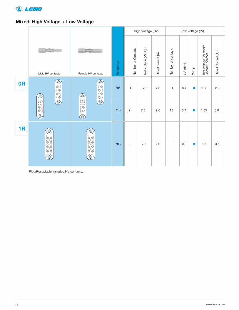
Mixed: High Voltage + Low Voltage
1
3
2
41 11
7
E
F
G
H
A
B
C
D
1
2
3
1
3
2
4111
7
E
F
G
H
A
B
C
D
1
2
3
703
1R
8 7.5 2.0 3 0.9 � 1.5 3.5
High Voltage (HV) Low Voltage (LV)
Reference
Male HV contacts Female HV contacts
4 7.5 2.0 4 0.7 � 1.35 2.0
2 7.5 2.0 13 0.7 � 1.35 3.0
704
713
0R
Plug/Receptacle includes HV contacts.

15www.lemo.com
® ®
FGG.0R.403.ZLME15
HV contactContact HT
Male
EGG.0R.403.ZLCE15
HV contactContact HT
Female
Typical Assembly of High Voltage Contact
HV Contacts: Fit the HV sleeve onto the cable dielectric, check that allthe HV conductor strands pass through the small hole.Crimp the contact using tool DPC.91.701.V fitted with positionerDCE.91.051.BVCM, set to position 3. Fit by turning the HV sub-assemblyon the HV sleeve and push until it butts. The two insulators shouldbe at the same level.
HV Contact Conductor Range 26-28 AWG
HV Contact Maximum Dielectric 1.5mm

www.lemo.com16
® ®
Num
ber of contacts
Impedance (Ω)
Type
Cable group
Num
ber of contacts
ø A (m
m)
Crimp contact
Test voltage (kV rms)1)
Rated current (A)1)
8 50 1R 1 3 0.9 � 1.5 3
22 0.5 � 0.6 0.5 1 50 1R 1 33 0.7 � 1.35 2.0
4 50 0R 1 4 0.7 � 1.35 2
2 50 0R 1 13 0.7 � 1.35 2
0.5 1 RR 1 4 0.5 � 0.6 0.5
Mixed Coax + Low Voltage
1
3
2
41 11
7
31
2 4
A
B
C
D
E
F
G
H
1
2
3
1
55
13
4 2
1
3
2
4111
7
A
B
C
D
E
F
G
H
1
2
3
1
55
804
813
0R
804
RR
1R
803
855
Reference
Male coax contacts Female coax contacts
Coax Low voltage (LV)
Plug/Receptacle inludes Coax contacts.

17www.lemo.com
® ®
FGG.0R.250.ZLME28
Coax contactContact coax
Male
EGG.0R.250.ZLCE28
Coax contactContact coax
Female
Typical Assembly of Coax Contact (Coax Types - RG-174/U, RG-188 A/U, RG-316/U) = Cable Group 1
Coax contacts: Fit the crimp ferrule onto the cable. Crimp the contact using tool DPC.91.701.V fitted with postionerDCE.91.050.RVCM, set to position 3. Fit by turning the coax sub-assembly on the central contact until the stop isreached, check that the central contact is in the correct position in relation to the sub-assembly (0.5 mm), fold backthe cable screen, place the crimp ferrule over the crimping area and complete the crimp using tool DPE.99.003.1K.
Male
Female
Typical Performance
VSWR / T.O.S.

www.lemo.com18
® ®
Mixed: Fluidic + Low Voltage
1
3
2
41 11
7
E
F
G
H
A
B
C
D
1
2
3
1
3
2
4111
7
E
F
G
H
A
B
C
D
1
2
3
003
1R
Reference
Male fluidic contacts Female fluidic contacts
4 8 5 4 0.7 � 1.35 2.0
2 8 5 13 0.7 � 1.35 2.0
8 8 5 3 0.9 � 1.5 3.0
004
013
0R
Num
ber of contacts
Flow (l/min)
Operating pressure (bars)
Num
ber of contacts
ø A (m
m)
Crimp contact
Test voltage (kV rms)1)
Rated current (A)1)
Fluidic Low voltage (LV)
Plug includes FGG.0R.010.AZA05 (w/ valve) contacts.Receptacle includes EGG.0R.010.AZL05 (w/o valve) contacts.

19www.lemo.com
® ®
Male fluidic / pnuematic contactFGG.0R.010.AZA05
Fluidic / Pneumatic Contacts
Part number
FGG.0R.010.AZA05 (2.7mm hose barb and valve)
Note: 3 – Hose fitting/ barb, 2 – retaining clips, 1 – male sleeve
Fluidic / pneumatic male contact
Male fluidic /pnuematic contactFGG.0R.010.AZL05
Part number
FGG.0R.010.AZL05 (1.7mm hose barb and non-valve)
Note: 3 – Hose fitting/ barb, 2 – retaining clips, 1 – male sleeve
Fluidic / pneumatic male contact

www.lemo.com20
® ®
Female fluidic / pnuematic contact
EGG.0R.010.AZA05
Fluidic / Pneumatic Contacts
Part number
EGG.0R.010.AZA05 (2.7mm hose barb and valve)
Note: 1 – female sleeve, 2 – retaining clips, 3 – Hose fitting/ barb,
Fluidic / pneumatic female contact
Female fluidic /pnuematic contactEGG.0R.010.AZL05
Part number
EGG.0R.010.AZL05 (1.7mm hose barb and non-valve)
Note: 1 – female sleeve, 2 – retaining clips, 3 – Hose fitting/ barb,
Fluidic / pneumatic female contact

21www.lemo.com
® ®
Ref.
GASV
Color
grayblueochregreen
7035603410286019
RAL code
Note: the connector shell material is Crastin® PBT.
Housings
The exact color depends on manufacturing process andmaterial pigments. For this reason some colors may differfrom present RAL code.

www.lemo.com22
® ®
Kit for cable clamping
FGG.RR.740.IZGFGG.0R.762.IZGFGG.1R.792.IZG
FGG
Series
RR 0R 1R
Colletsize
40 62 92
min.
1.0 1.6 2.0
max.
4.0 6.2 9.2
Part number
Bracket
PCB / C.I.
H
L
GEE.RR.145.NZZGEE.RR.146.NZZGEE.RR.147.NZZGEE.0R.145.NZZGEE.0R.146.NZZGEE.0R.147.NZZGEE.1R.145.NZZGEE.1R.146.NZZGEE.1R.147.NZZ
GEE
Dimensions (mm) Series L H
10.00 3.00 RR 12.25 5.25 14.00 7.00 16.50 4.50 0R 18.25 6.25 22.50 10.50 20.75 6.25 1R 25.00 10.50 32.50 18.00
� Body material: Brass (UNS C 34500)� Screws: Brass (UNS C 34500)
Part number
Accessories
Collets

23www.lemo.com
® ®
Insulator part number Male contact Female contact
Type
male female
Insulators for crimp contactsFGG-EGG
FGG.RR.313.YL EGG.RR.413.YL313RR
FGG.0R.310.YL EGG.0R.410.YLFGG.0R.317.YL EGG.0R.417.YLFGG.0R.337.YL EGG.0R.437.YL
310317337
0R
FGG.1R.328.YL EGG.1R.428.YLFGG.1R.336.YL EGG.1R.436.YLFGG.1R.365.YL EGG.1R.465.YLFGG.1R.367.YL EGG.1R.467.YL
328336365367
1R
ø A
ø A
ø C
ø C
ø A ø C
ø A ø C
FGG.00.554.ZZC EGG.00.654.ZZM 313 0.5 0.45
RR
FGG.0B.560.ZZC EGG.0B.660.ZZMFGG.0B.555.ZZC EGG.0B.655.ZZMFGG.00.554.ZZC EGG.00.654.ZZM
310 0.9 1.10 317 0.7 0.80 337 0.5 0.45
0R
FGG.0B.560.ZZC EGG.0B.660.ZZMFGG.0B.555.ZZC EGG.0B.655.ZZMFGG.0B.554.ZZC EGG.1B.654.ZZM
328 0.9 1.10 336 0.7 0.80 365/367 0.5 0.45
1R
Contact part number
Male Female Types
ø A (m
m)
ø C (m
m)
FGG.0B.561.ZZC EGG.0B.661.ZZMFGG.0B.562.ZZC EGG.0B.662.ZZMFGG.0B.556.ZZC EGG.0B.656.ZZM
310 0.9 0.80 310 0.9 0.45 317 0.7 0.45
0R
FGG.0B.561.ZZC EGG.0B.661.ZZMFGG.0B.562.ZZC EGG.0B.662.ZZMFGG.0B.556.ZZC EGG.0B.656.ZZM
328 0.9 0.80 328 0.9 0.45 336 0.7 0.45
1R
Contact part number
Male Female Types
ø A (m
m)
ø C (m
m)
Fig. 1 Fig. 2
Crimp contactsFGG-EGG
Spare parts

24www.lemo.com
® ®
Supplier
LEMODANIELSASTRO
DPC.91.701.V1)
MH8601)
6163361)
1) According to specification MIL-C-22520/7-01.
Manual crimping tools
Part number
contact ø 0.5-0.7-0.9
DCE.91.050.0VC DCE.91.050.0VM
These positioners are suitable for use with both manual andpneumatic crimping tools according to the MIL-C-22520/7-01 standard.
Connector + Contact
Conductor Type AWG
313 0.5 0.45 1 28-30-32
Positioners part number
For male For female contact contact
Positioners for crimp contacts ø 0.5-0.7 and 0.9 mmDCE
male female RR
DCE.91.090.BVC DCE.91.090.BVM
DCE.91.090.AVC DCE.91.090.AVM
DCE.91.070.BVC DCE.91.070.BVM
DCE.91.050.0VC DCE.91.050.0VM
0.9 1.10 1 20-22-24 310 0.9 0.80 2 22-24-26 0.9 0.45 2 28-30-32 0.7 0.80 1 22-24-26 317 0.7 0.45 2 28-30-32 337 0.5 0.45 1 28-30-32
DCE.91.090.BVC DCE.91.090.BVM
DCE.91.090.AVC DCE.91.090.AVM
DCE.91.070.BVC DCE.91.070.BVM
DCE.91.050.BVC DCE.91.051.BVM
0.9 1.10 1 20-22-24 328 0.9 0.80 2 22-24-26 0.9 0.45 2 28-30-32 0.7 0.80 1 22-24-26 336 0.7 0.45 2 28-30-32 365/367 0.5 0.45 1 28-30-32
0R
1R
ø A
ø A
ø C
ø C
Fig. 1
ø A ø C
ø A ø C
Fig. 2
ø A
ø C
Fig.
Note: a wide variation of strand number and diameter combinations are quoted asbeing AWG, some of which do not have a large enough cross section to guaranteea crimp as per either MIL-C-22520/1-01 or /7-01. Our technical department is atyour disposal to study and propose a solution to all your applications.
Part number
DPE.99.003.1K
Cablegroup
1
Manual crimping tool w/ die for coax contactsDPE
Tooling
25www.lemo.com
® ®
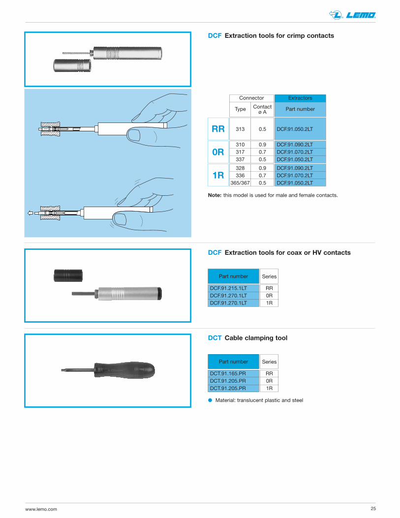
Extraction tools for crimp contacts
Note: this model is used for male and female contacts.
DCF
DCF.91.050.2LT
Connector
Contact Type ø A
313 0.5
RR
DCF.91.090.2LTDCF.91.070.2LTDCF.91.050.2LT
310 0.9 317 0.7 337 0.5
0R
DCF.91.090.2LTDCF.91.070.2LTDCF.91.050.2LT
328 0.9 336 0.7365/367 0.5
1R
Extractors
Part number
Extraction tools for coax or HV contactsDCF
Cable clamping toolDCT
� Material: translucent plastic and steel
DCT.91.165.PRDCT.91.205.PRDCT.91.205.PR
Series
RR 0R 1R
Part number
DCF.91.215.1LTDCF.91.270.1LTDCF.91.270.1LT
Series
RR 0R 1R
Part number

www.lemo.com26
® ®
P1 P2 ø A B C H L R ø A B H L R L ± 0.1
ø A ± 0.1
C°
H ±
0.1
B ±
0.1
R (4x)
P1 - EGG
B ±
0.1
L ± 0.1
ø A ± 0.1
R ± 0.1
H ±
0.1
P2 - EBG, PBG
Series
RR0R1R
1.7 7.8 5 11 3.5 – – – – – – 2.2 14.2 7 17 5.7 1.0 2.2 24.6 30 9.2 4.7 3.2 22.2 10 25 8.5 1.2 3.2 37.4 45.0 12.8 6.4
R series
PCB drilling pattern
Fixed receptacle with straight print contact (EGG models)
0.75
ø 1.7 ± 0.1
11 ±
0.1
13 x ø 0.7 ± 0.1
1
2.5
RR.313
ø 2.2 ± 0.1
17 ±
0.1
10 x ø 0.7 ± 0.1
1.2
4.1
2.2
0R.310
0.95
ø 2.2 ± 0.1
17 ±
0.1
17 x ø 0.7 ± 0.1
1.6
3.75
0R.317
0.75
¿ 2.2 ± 0.1
37 x ¿ 0.7 ± 0.1
1.8
0.9
3.2
17 ±
0.1
0R.337
1.15
ø 3.2 ± 0.1
25 ±
0.1
28 x ø 0.7 ± 0.1
2.85
1.9
4.45
1R.328
0.95
ø 3.2 ± 0.1
25 ±
0.1
36 x ø 0.7 ± 0.1
2.05
5.7
3.95
1R.336
ø 3.2 ± 0.1
25 ±
0.1
65 x ø 0.7 ± 0.1
3.25
1.3
3.7
0.8
1R.365
33 x ø 0.7 ± 0.1
6 x 1.1
4 x 1.5
22 x ø 0.5 ± 0.1
1.5
1.5
3.2
3.95
1.73
4.57
3.7
2.9
25 ±
0.1
1.73
ø 3.2 ± 0.1
1R.855
Panel cut-outs
Fixed receptacle with straight print contact (EBG models)
1.15
ø 3.2 ± 0.1
25 ±
0.1
28 x ø 0.7 ± 0.1
2.85
1.9
4.45
1R.328
0.95
36 x ø 0.7 ± 0.1
5.7
2.0513.9
5
1R.336
65 x ø 0.7 ± 0.1
3.25
1.313.7
0.8
1R.365
ø 3.2 ± 0.125
± 0
.1
67 x ø 0.7 ± 0.1
3.25
1.3
3.7
0.8
1R.367

27www.lemo.com
® ®
Outer shell
The R series is made of lightweight polyester resin Crastin® PBT from DupontTM
with metal latches.
Technical characteristics
Insulator
The insulators are made of PEEK plastic. The insulators of the coax contact and the high voltagecontact are Teflon
TM.

www.lemo.com28
® ®
Bronze (UNS C 54400) 0.5 3 1.5 Cu-Be (FS QQ-C-530)
Cu-Be (FS QQ-C-530) – – – Stainless steel
Electrical contact
Technical description
The secure reliable electromechanical connectionachieved with LEMO female cylindrical contacts is mainly due to two important design features:
1. Prod proof entry on the mating side which ensuresperfect concentric mating even with carelessly handled connectors.
2. The pressure spring, with good elasticity, maintains aconstant even force on the male contact when mated.The leading edge of the pressure spring preserves the surface treatment (gold-plated) and preventsundue wear.
Contact material and treatment
Type
Male crimp
Male print
Surf. treatment (µm) Material (standard) Cu Ni Au1)
Brass (UNS C 34500) Brass (UNS C 38500) 0.5 3 1.0Brass (UNS C 38500)
Femalle crimpFemale print
Clips
Brass – 33) –Wire2)
AuNiCu
Bronzeor brass
Notes: the standard surface treatment are as follows:– nickel: FS QQ-N-290A or MIL-C-26074C– gold: ISO 4523.1) minimum value2) for elbow print contacts3) treatment completed by 6 µm Sn-Pb tin-plating
LEMO female contacts are made of bronze beryllium(QQ-C-530) or bronze (UNS C 54400). These materialsare chosen because of their high modulus of elasticity,their excellent electrical conductivity and a high mechan-ical strength.
LEMO male solder and print contacts are made of brass(UNS C 38500). Male crimp contacts are made of brass(UNS C 34500) or annealed brass (UNS C 38500) withoptimum hardness (HV) for crimping onto the wire.

29www.lemo.com
® ®
Crimp contacts
1 2
Advantages of crimping
3
Crimp contacts are available in standard version (form 1)for mounting maximum size conductors.For some dimensions, these crimp contacts can be pro-duced with reduced crimp barrels (form 2) for mountingreduced size conductors.
The square form crimp method is used (MIL-C-22520F,class I, type 2) photo 1 for unipole contacts.
For multipole contacts the standard four identer crimpmethod is used, MIL-C-22520F, class I, type 1), photo 2.The crimp method requires a controlled compression toobtain a symmetrical deformation of the conductor strandand of the contact material. The radial hole in the side ofthe contact makes it possible to check whether the con-ductor is correctly positioned within the contact. A goodcrimping is characterized by only slightly reduced con-ductor section and practically no gap.
For optimum crimping of bronze or brass contacts theyare annealed to relieve internal stress and reduce materialhardening during the crimping process.Only the crimping zone is annealed with the help of aninduction heating machine designed by the LEMOResearch and Development Department (see photo 3).
– practical, quick contact fixing outside the insulator– possible use at high temperature– no risk of heating the insulator during the conductor-contact fixing
– high tensile strength
Crimp contacts
Fig. 1 Fig. 2
The crimp contacts can be with two forms: a standardcrimp barrel for large conductors (see fig. 1) or with areduced crimp barrel for smaller conductors (see fig. 2).
The range of cable dimensions that can be crimped intoour contacts are indicated on the table on page 9.

LEMO HEADQUARTERS
SWITzERLANDLEMO SA Chemin des Champs-Courbes 28 - P.O. Box 194 - CH-1024 EcublensTel. (+41 21) 695 16 00 - Fax (+41 21) 695 16 02 - e-mail: [email protected]
LEMO SUbSIDIARIES
AUSTRIALEMO Elektronik GesmbHLemböckgasse 49/E6-31230 WienTel: (+43 1) 914 23 20 0Fax: (+43 1) 914 23 20 [email protected]
bRAzILLEMO Latin America LtdaAv. Jose Rocha Bonfirm,214 Salas 224 / 225Condominio Praca CapitalEd ChicagoCampinas / SP - Brasil -13080-650Tel: +55 (11) 98689 [email protected]
CANADALEMO Canada Inc44 East Beaver Creek Road, Unit 20Richmond Hill, Ontario L4B 1G8Tel: (+1 905) 889 [email protected]
CHINA / HONG KONGLEMO Electronics (Shanghai) Co., Ltd First Floor, Block E18 Jindian Road, PudongShanghai, China 201206Tel: (+86 21) 5899 7721Fax: (+86 21) 5899 [email protected]
DENMARKLEMO Denmark A/SGammel Mosevej 462820 GentofteTel: (+45) 45 20 44 00Fax: (+45) 45 20 44 [email protected]
FRANCELEMO France Sàrl24/28 Avenue Graham BellBâtiment Balthus 4Bussy Saint Georges77607 Marne la Vallée Cedex 3Tel: (+33 1) 60 94 60 94Fax: (+33 1) 60 94 60 [email protected]
GERMANYLEMO Elektronik GmbHHanns-Schwindt-Str. 681829 München Tel: (+49 89) 42 77 03Fax: (+49 89) 420 21 [email protected]
HUNGARYREDEL Elektronika KftNagysándor József u. 6-12H-1201 BudapestTel: (+36 1) 421 47 10Fax: (+36 1) 421 47 [email protected]
ITALYLEMO Italia srlViale Lunigiana 2520125 MilanoTel: (+39 02) 66 71 10 46Fax: (+39 02) 66 71 10 [email protected]
JAPANLEMO Japan Ltd2-7-22, Mita, Minato-ku, Tokyo, 108-0073Tel: (+81 3) 54 46 55 10Fax: (+81 3) 54 46 55 [email protected]
NETHERLANDS / bELGIUMLEMO Connectors beneluxDe Trompet 10601967 DD HeemskerkTel. (+31) 251 25 78 20Fax (+31) 251 25 78 [email protected]
NORWAY / ICELANDLEMO Norway A/SStanseveien 6B0975 OsloTel: (+47) 22 91 70 40Fax: (+47) 22 91 70 [email protected]
SINGAPORELEMO Asia Pte Ltd4 Leng Kee Road, #06-09 SiS Building Singapore 159088Tel: (+65) 6476 0672Fax: (+65) 6474 [email protected]
SPAIN / PORTUGALIbERLEMO SAUBrasil, 45, 08402 GranollersBarcelonaTel: (+34 93) 860 44 20Fax: (+34 93) 879 10 [email protected]
SWEDEN / FINLANDLEMO Nordic AbMariehällsvägen 39A 168 65 BrommaTel: (+46 8) 635 60 60Fax: (+46 8) 635 60 [email protected]
SWITzERLANDLEMO Verkauf AGGrundstrasse 22 B6343 RotkreuzTel: (+41 41) 790 49 40Fax: (+41 41) 790 49 [email protected]
UNITED KINGDOMLEMO UK Ltd12-20 North StreetWorthing, West Sussex, BN11 1DUTel: (+44 1903) 23 45 43Fax: (+44 1903) 20 62 [email protected]
LEMO DISTRIbUTORS
AUSTRALIA, bRAzIL, CzECH REPUbLIC,
GREECE, INDIA, ISRAEL, NEW zEALAND,
PAKISTAN, POLAND, RUSSIA, SOUTH
AFRICA, SOUTH KOREA, TAIWAN, TURKEY,
UKRAINE
LEMO USA Inc
P.O. Box 2408 • Rohnert Park, CA 94927-2408Tel: (+1 707) 578 8811 • (+1 800) 444 5366 • Fax: (+1 707) 578 [email protected]
www.lemo.com
CAT.RS.LUS.P102517