Plastic Deformation Elementary Dislocation Theory · Plastic Deformation & Elementary Dislocation...
84
Plastic Deformation & Elementary Dislocation Theory Lecture Course for the Students of Metallurgical Engineering V V Kutumbarao LECTURE - 2
Transcript of Plastic Deformation Elementary Dislocation Theory · Plastic Deformation & Elementary Dislocation...
Plastic Deformation &
Elementary Dislocation Theory
Lecture Course for the
Students of Metallurgical Engineering
V V Kutumbarao
LECTURE - 2
2
Brief Review of
Part – 1: The Etchpit
Enter the Dislocation
3
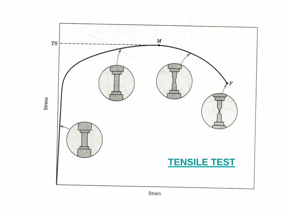
TENSILE TEST
4
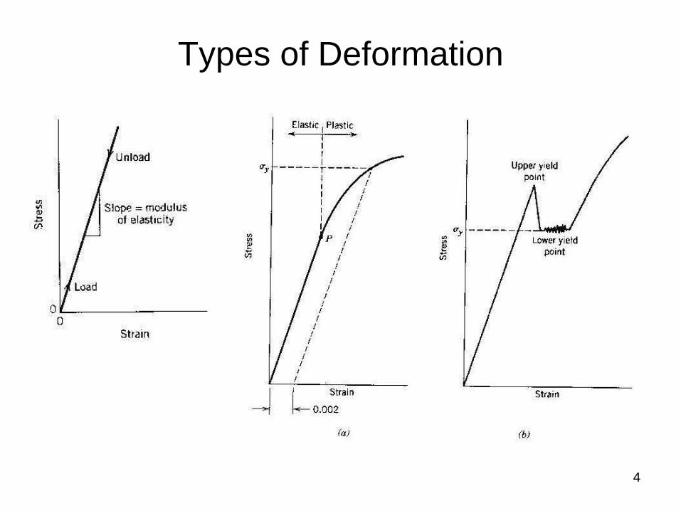
Types of Deformation
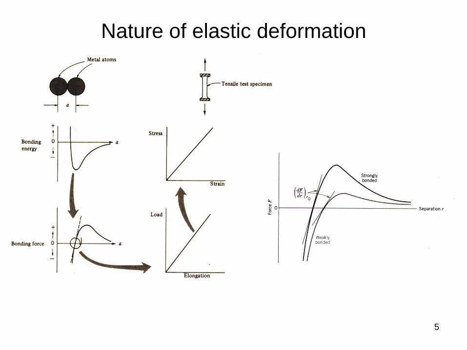
Nature of elastic deformation
5
6
To understand this, we first need to understand
that metallic materials are normally
crystalline in nature and the
are: fcc, bcc and hcp
What about plastic deformation?
How does it occur on the atomic scale?
Common Crystal Structures
7
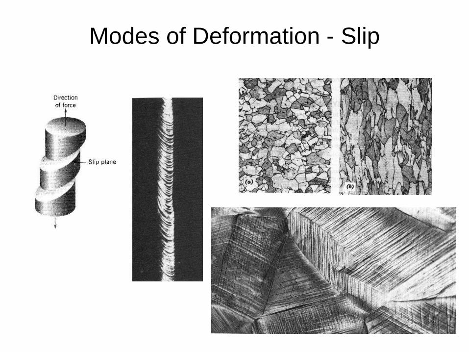
Modes of Deformation - Slip
8
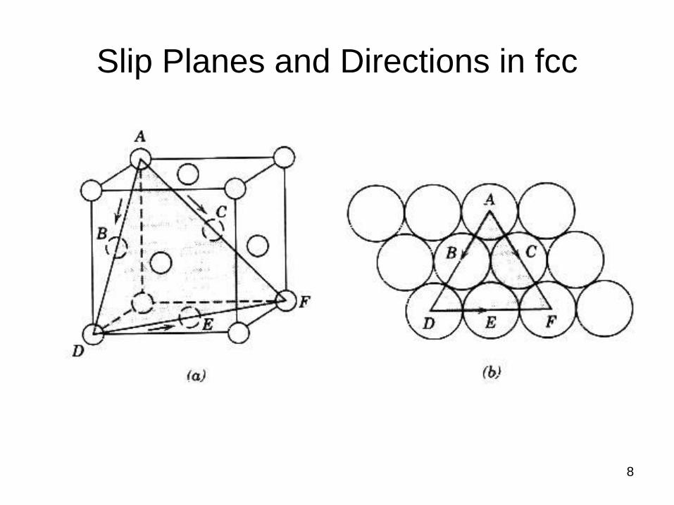
Slip Planes and Directions in fcc
9
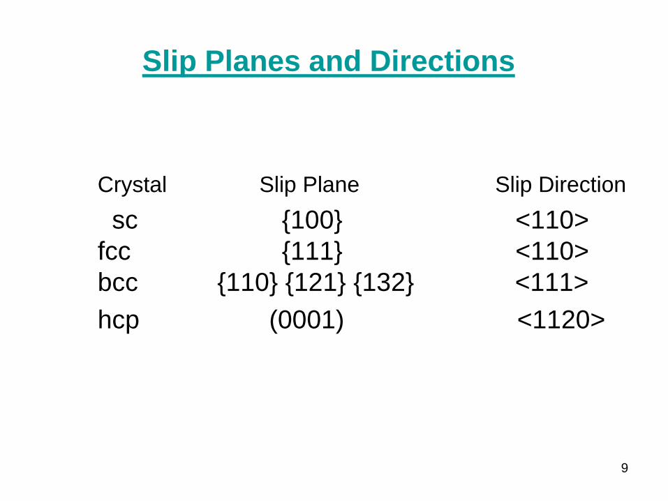
Crystal Slip Plane Slip Direction
sc {100} <110>
fcc {111} <110>
bcc {110} {121} {132} <111>
hcp (0001) <1120>
Slip Planes and Directions
10
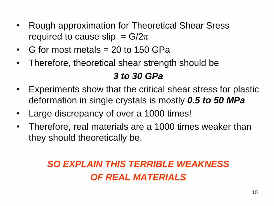
• Rough approximation for Theoretical Shear Sress
required to cause slip = G/2p
• G for most metals = 20 to 150 GPa
• Therefore, theoretical shear strength should be
3 to 30 GPa
• Experiments show that the critical shear stress for plastic
deformation in single crystals is mostly 0.5 to 50 MPa
• Large discrepancy of over a 1000 times!
• Therefore, real materials are a 1000 times weaker than
they should theoretically be.
SO EXPLAIN THIS TERRIBLE WEAKNESS
OF REAL MATERIALS

11
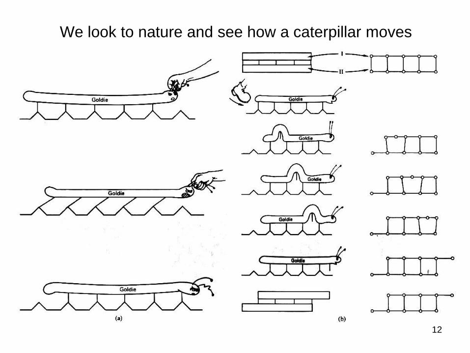
May be our model for the
mechanism of plastic deformation
by slip wasn’t quite right!
12
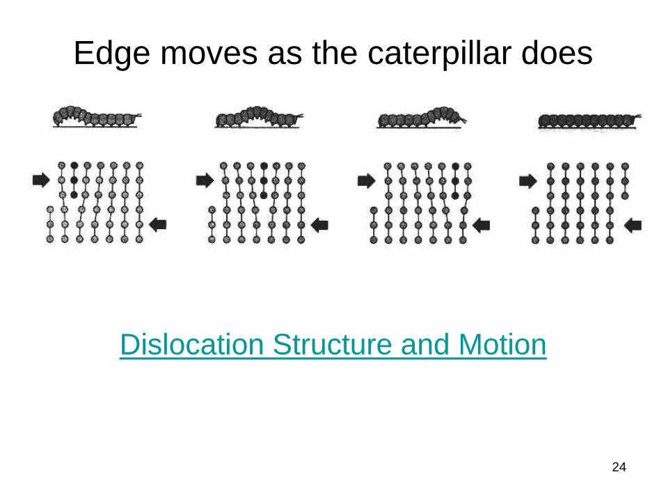
We look to nature and see how a caterpillar moves
13
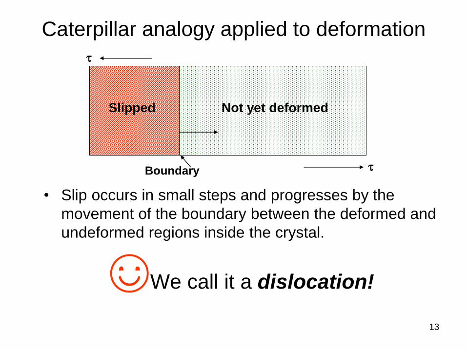
Caterpillar analogy applied to deformation
• Slip occurs in small steps and progresses by the
movement of the boundary between the deformed and
undeformed regions inside the crystal.
☺We call it a dislocation!
Boundary
Slipped Not yet deformed
t
t
14
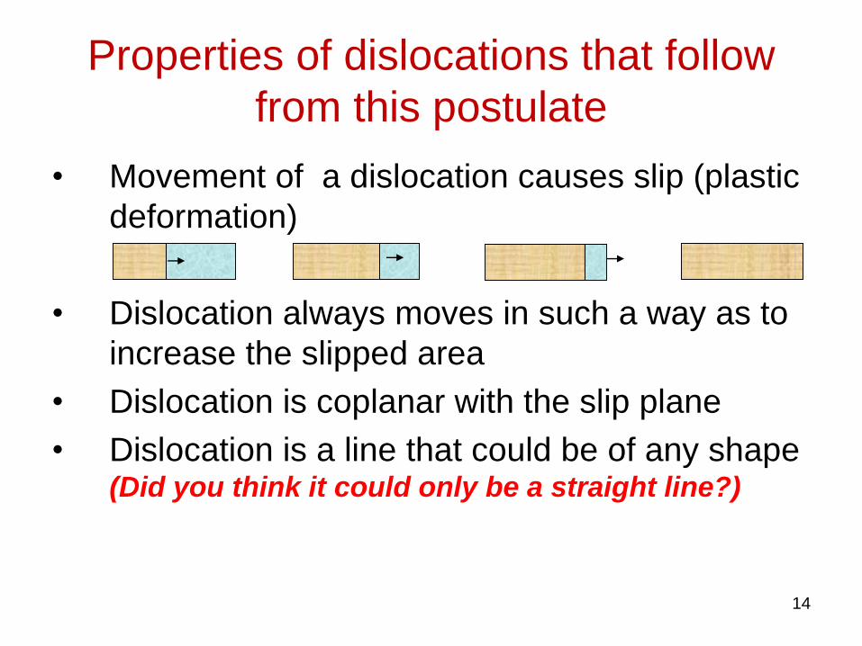
Properties of dislocations that follow
from this postulate
• Movement of a dislocation causes slip (plastic
deformation)
• Dislocation always moves in such a way as to
increase the slipped area
• Dislocation is coplanar with the slip plane
• Dislocation is a line that could be of any shape (Did you think it could only be a straight line?)
• Dislocation line can not end inside a crystal
• Dislocation can only end at a surface, which can
be the external surface of the crystal itself if it is
a single crystal, or an internal surface like a
grain boundary in a polycrystalline material or a
phase boundary in a multiphase material.
15
Properties of dislocations (contd..)
16
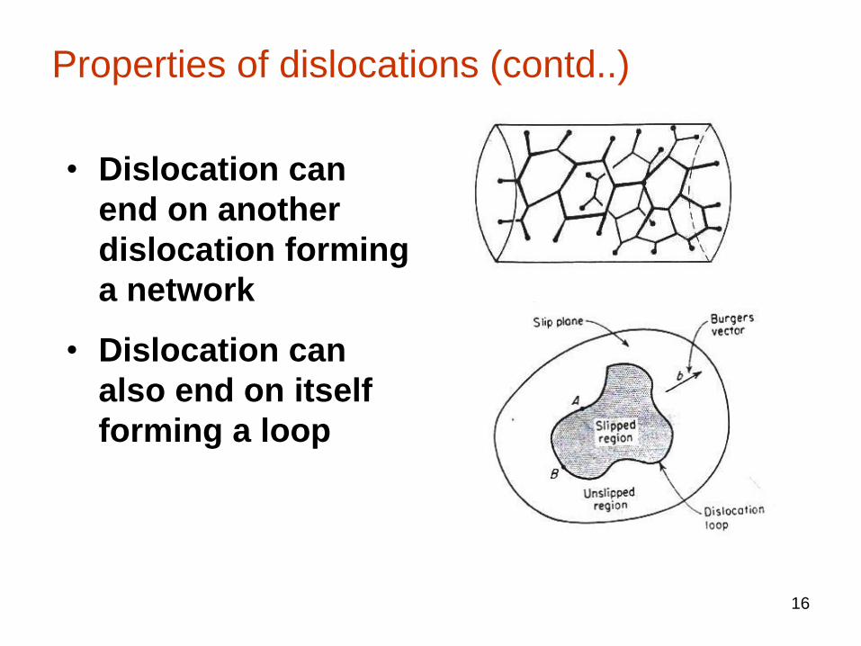
Properties of dislocations (contd..)
• Dislocation can
end on another
dislocation forming
a network
• Dislocation can
also end on itself
forming a loop

17
Dislocation Movement causes Slip
18
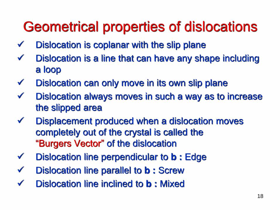
Geometrical properties of dislocations
Dislocation is coplanar with the slip plane
Dislocation is a line that can have any shape including
a loop
Dislocation can only move in its own slip plane
Dislocation always moves in such a way as to increase
the slipped area
Displacement produced when a dislocation moves
completely out of the crystal is called the
“Burgers Vector” of the dislocation
Dislocation line perpendicular to b : Edge
Dislocation line parallel to b : Screw
Dislocation line inclined to b : Mixed
19
Burgers CircuitAn easy method for finding the burgers vector of a dislocation
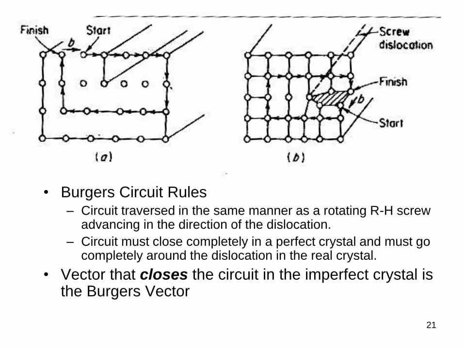
Burgers Circuit Rules
1. Choose arbitrarily a +ve direction for the dislocation, say
direction under the paper for a + ve edge. Circuit
traversed in the same manner as a rotating R-H screw
advancing in the direction of the dislocation.
2. Describe a step by step circuit in a perfect crystal that
closes completely.
3. Repeat it in the imperfect crystal
4. Vector that closes the circuit in the imperfect crystal is the Burgers Vector
20
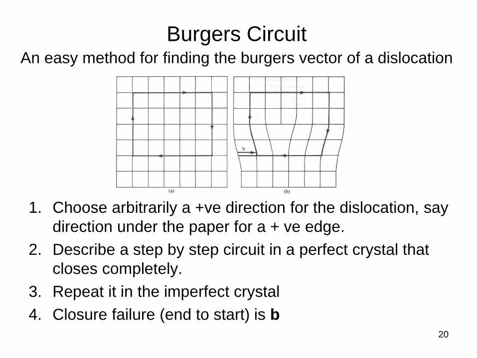
Burgers CircuitAn easy method for finding the burgers vector of a dislocation
1. Choose arbitrarily a +ve direction for the dislocation, say
direction under the paper for a + ve edge.
2. Describe a step by step circuit in a perfect crystal that
closes completely.
3. Repeat it in the imperfect crystal
4. Closure failure (end to start) is b
21
• Burgers Circuit Rules– Circuit traversed in the same manner as a rotating R-H screw
advancing in the direction of the dislocation.
– Circuit must close completely in a perfect crystal and must go completely around the dislocation in the real crystal.
• Vector that closes the circuit in the imperfect crystal is the Burgers Vector
22
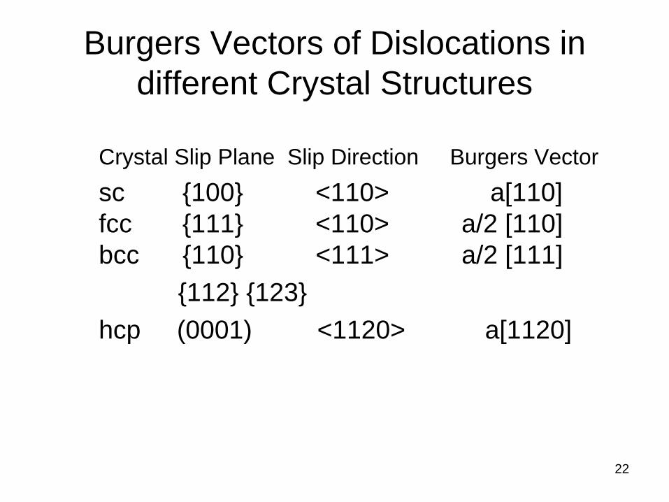
Burgers Vectors of Dislocations in
different Crystal Structures
Crystal Slip Plane Slip Direction Burgers Vector
sc {100} <110> a[110]
fcc {111} <110> a/2 [110]
bcc {110} <111> a/2 [111]
{112} {123}
hcp (0001) <1120> a[1120]
23
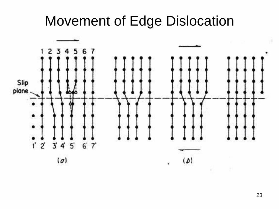
Movement of Edge Dislocation
24
Edge moves as the caterpillar does
Dislocation Structure and Motion
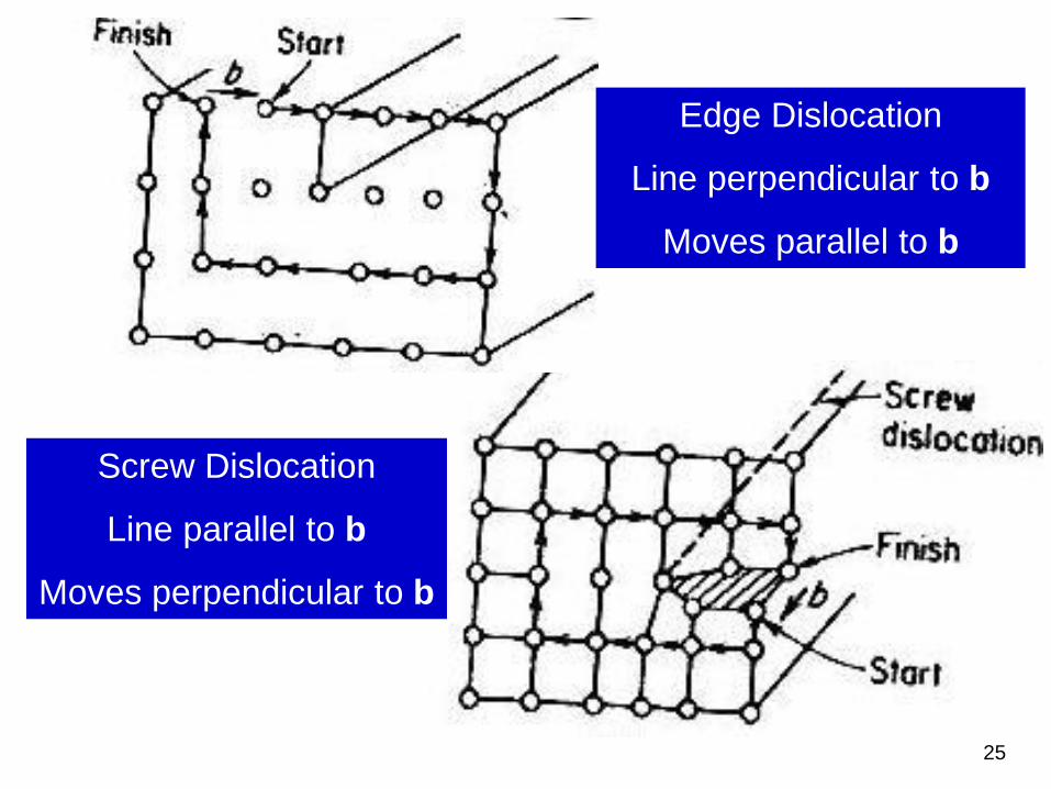
25
Edge Dislocation
Line perpendicular to b
Moves parallel to b
Screw Dislocation
Line parallel to b
Moves perpendicular to b
26
Part – 2: The Prism Loop
Going in deeper
27
Lots of maths coming up.
But don’t worry too much about it. Just
concentrate on the physical significance
of the equations.Incidentally, most of the dislocation theory was
originally developed by mechanical and civil
engineers! The equations were all obtained by
continuum mechanics: treatment consisted of
making a cut in the surface of a cylinder and
either pushing it in slightly (edge) or twisting it
slightly (screw).
28
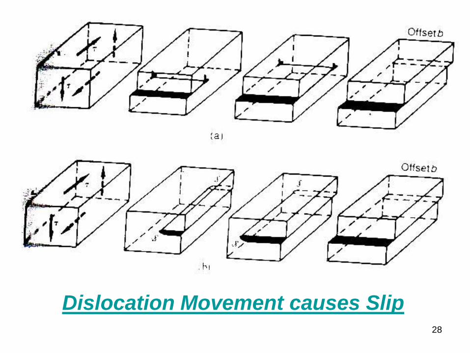
Dislocation Movement causes Slip
29
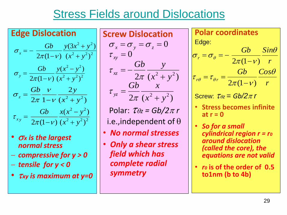
Stress Fields around Dislocations
Edge Dislocation
• sx is the largest normal stress
compressive for y > 0 tensile for y < 0
• txy is maximum at y=0
222
22
)(
)(
)1(2 yx
yxyGby
ps
)(
2
12 22 yx
yGbz
ps
222
22
)(
)(
)1(2 yx
yxxGbyx
pt
222
22
)(
)3(
)1(2 yx
yxyGbx
ps
Screw Dislocation
Polar: tqz = Gb/2p r
i.e.,independent of q
• No normal stresses
• Only a shear stress field which has complete radial symmetry
)(2
)(2
0
0
22
22
yx
xGbyx
yGb
yz
xz
xy
zyx
pt
pt
tsss
Polar coordinatesEdge:
Screw: tqz = Gb/2p r
• Stress becomes infinite at r = 0
• So for a small cylindrical region r = r0
around dislocation (called the core), the equations are not valid
• r0 is of the order of 0.5 to1nm (b to 4b)
r
SinGbr
q
pss q
)1(2
r
CosGbrr
q
ptt qq
)1(2
30
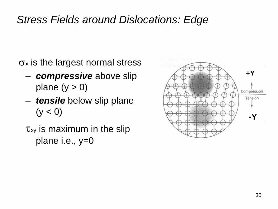
sx is the largest normal stress
– compressive above slip
plane (y > 0)
– tensile below slip plane
(y < 0)
txy is maximum in the slip
plane i.e., y=0
-Y
+Y
Stress Fields around Dislocations: Edge
31
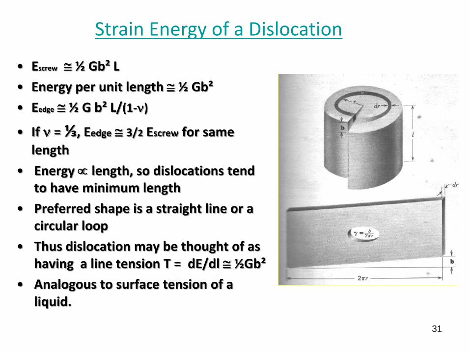
• Escrew ½ Gb² L
• Energy per unit length ½ Gb²
• Eedge ½ G b² L/(1-)
• If = ⅓, Eedge 3/2 Escrew for same
length
• Energy length, so dislocations tend to have minimum length
• Preferred shape is a straight line or a circular loop
• Thus dislocation may be thought of as having a line tension T = dE/dl ½Gb²
• Analogous to surface tension of a liquid.
Strain Energy of a Dislocation
32
So far so good.
We postulated the existence of a dislocation
and derived lots of its properties.
OK, but what about our basic problem?
….. an explanation for the observation that
strength of real materials is
far less than theoretical shear strength
Can our dislocation theory explain it?
33
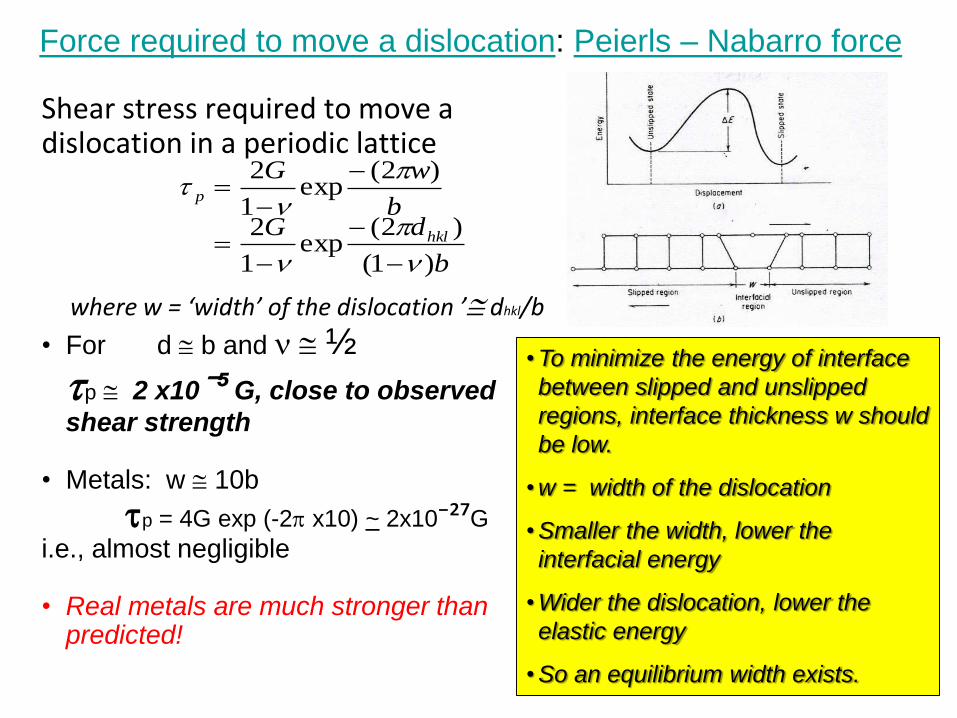
Shear stress required to move a dislocation in a periodic lattice
where w = ‘width’ of the dislocation ’ dhkl/b
• For d b and ½
tp 2 x10⁻⁵ G, close to observed
shear strength
• Metals: w 10b
tp = 4G exp (-2p x10) ~ 2x10⁻²⁷G
i.e., almost negligible
• Real metals are much stronger than predicted!
b
dGb
wG
hkl
p
)1(
)2(exp
1
2
)2(exp
1
2
p
p
t
• To minimize the energy of interface
between slipped and unslipped
regions, interface thickness w should
be low.
• w = width of the dislocation
• Smaller the width, lower the
interfacial energy
• Wider the dislocation, lower the
elastic energy
• So an equilibrium width exists.
Force required to move a dislocation: Peierls – Nabarro force
34
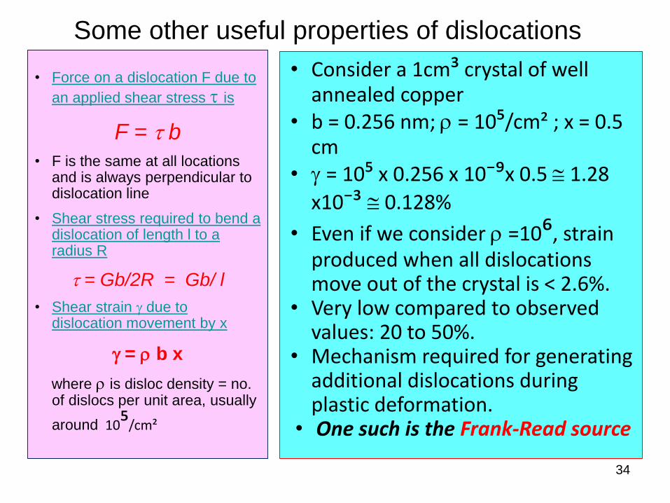
Some other useful properties of dislocations
• Force on a dislocation F due to
an applied shear stress t is
F = t b• F is the same at all locations
and is always perpendicular to dislocation line
• Shear stress required to bend a dislocation of length l to a radius R
t = Gb/2R = Gb/ l
• Shear strain g due to dislocation movement by x
g = r b x
where r is disloc density = no. of dislocs per unit area, usually
around 10⁵/cm²
• Consider a 1cm³ crystal of well annealed copper
• b = 0.256 nm; r = 10⁵/cm² ; x = 0.5 cm
• g = 10⁵ x 0.256 x 10⁻⁹x 0.5 1.28
x10⁻³ 0.128%
• Even if we consider r =10⁶, strain produced when all dislocations move out of the crystal is < 2.6%.
• Very low compared to observed values: 20 to 50%.
• Mechanism required for generating additional dislocations during plastic deformation.
• One such is the Frank-Read source
35
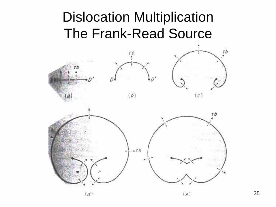
Dislocation Multiplication
The Frank-Read Source
36
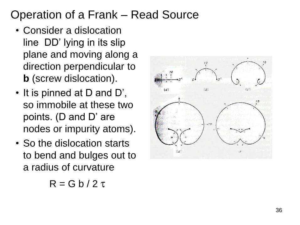
Operation of a Frank – Read Source
• Consider a dislocation
line DD’ lying in its slip
plane and moving along a
direction perpendicular to
b (screw dislocation).
• It is pinned at D and D’,
so immobile at these two
points. (D and D’ are
nodes or impurity atoms).
• So the dislocation starts
to bend and bulges out to
a radius of curvature
R = G b / 2 t
37
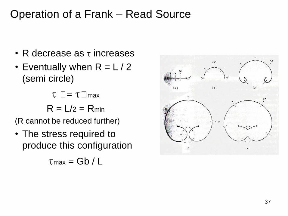
• R decrease as t increases
• Eventually when R = L / 2
(semi circle)
t = t max
R = L/2 = Rmin
(R cannot be reduced further)
• The stress required to
produce this configuration
tmax = Gb / L
Operation of a Frank – Read Source
38
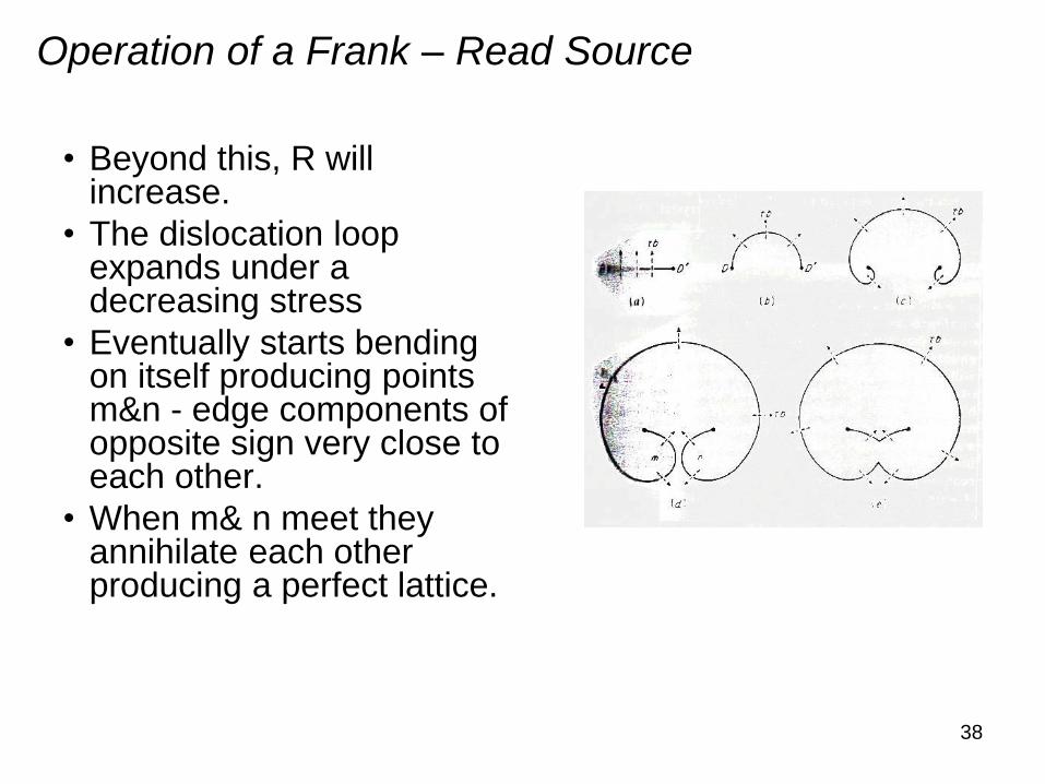
• Beyond this, R will increase.
• The dislocation loop expands under a decreasing stress
• Eventually starts bending on itself producing points m&n - edge components of opposite sign very close to each other.
• When m& n meet they annihilate each other producing a perfect lattice.
Operation of a Frank – Read Source
39
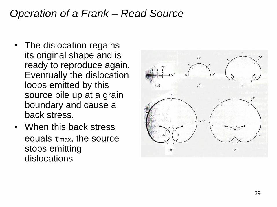
• The dislocation regains its original shape and is ready to reproduce again. Eventually the dislocation loops emitted by this source pile up at a grain boundary and cause a back stress.
• When this back stress
equals tmax, the source stops emitting dislocations
Operation of a Frank – Read Source
40
Dislocation Multiplication: The Frank-Read Source
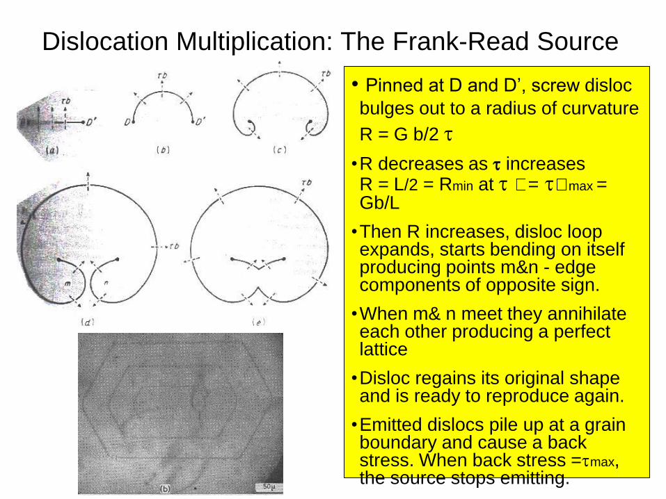
• Pinned at D and D’, screw disloc
bulges out to a radius of curvature
R = G b/2 t
•R decreases as t increases R = L/2 = Rmin at t = t max = Gb/L
•Then R increases, disloc loop expands, starts bending on itself producing points m&n - edge components of opposite sign.
•When m& n meet they annihilate each other producing a perfect lattice
•Disloc regains its original shape and is ready to reproduce again.
•Emitted dislocs pile up at a grain boundary and cause a back stress. When back stress =tmax, the source stops emitting.
Elementary Dislocation Theory
End of Lecture 2
42
Part 3: The Partials
Losing Innocence
and Getting Real
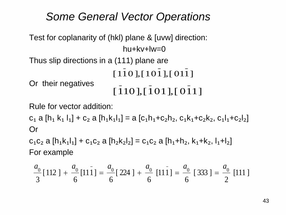
Some General Vector Operations
Test for coplanarity of (hkl) plane & [uvw] direction:
hu+kv+lw=0
Thus slip directions in a (111) plane are
Or their negatives
Rule for vector addition:
c₁ a [h₁ k₁ l₁] + c₂ a [h₁k₁l₁] = a [c₁h₁+c₂h₂, c₁k₁+c₂k₂, c₁l₁+c₂l₂]
Or
c₁c₂ a [h₁k₁l₁] + c₁c₂ a [h₂k₂l₂] = c₁c₂ a [h₁+h₂, k₁+k₂, l₁+l₂]
For example
] 111[ 2
] 333 [ 6
] 1 11[ 6
] 224 [6
] 1 11[ 6
] 112 [ 3
000000aaaaaa
43
] 1 01 [], 1 0 1 [], 0 1 1 [
] 1 1 0 [], 1 0 1 [], 10 1 [
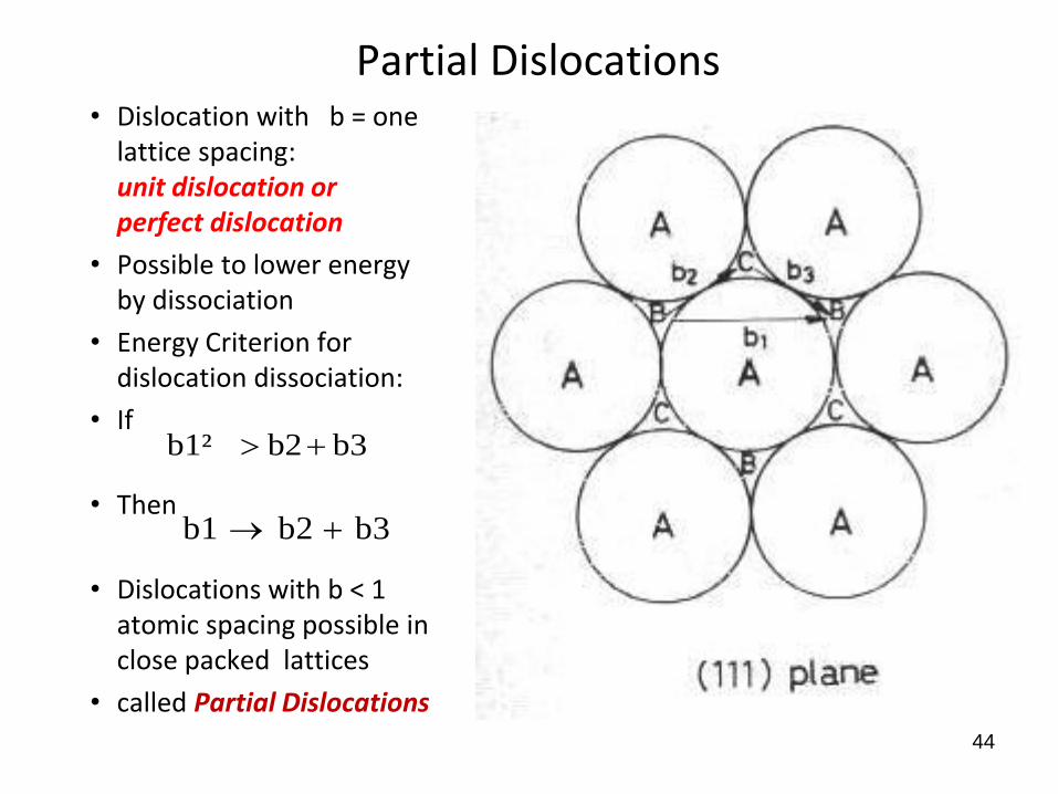
Partial Dislocations• Dislocation with b = one
lattice spacing: unit dislocation or perfect dislocation
• Possible to lower energy by dissociation
• Energy Criterion for dislocation dissociation:
• If
• Then
• Dislocations with b < 1 atomic spacing possible in close packed lattices
• called Partial Dislocations
b3b2b1
b3 b2b1²
44
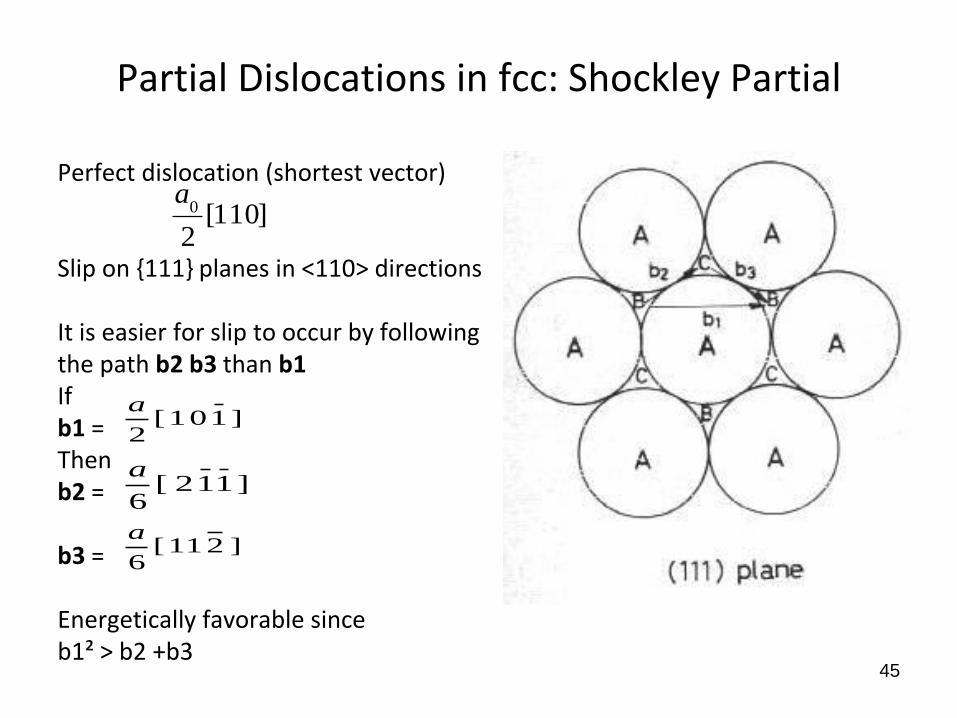
Partial Dislocations in fcc: Shockley Partial
Perfect dislocation (shortest vector)
Slip on {111} planes in <110> directions
It is easier for slip to occur by following the path b2 b3 than b1If b1 = Then b2 =
b3 =
Energetically favorable since b1² > b2 +b3
]110[2
0a
45
] 1 0 1 [ 2
a
] 1 1 2 [ 6
a
] 2 1 1 [ 6
a
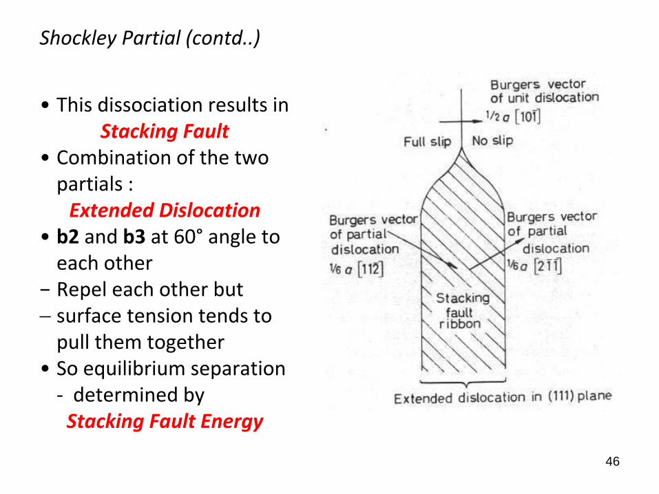
Shockley Partial (contd..)
• This dissociation results inStacking Fault
• Combination of the two partials :
Extended Dislocation • b2 and b3 at 60° angle to
each other− Repel each other but surface tension tends to
pull them together • So equilibrium separation
- determined byStacking Fault Energy
46
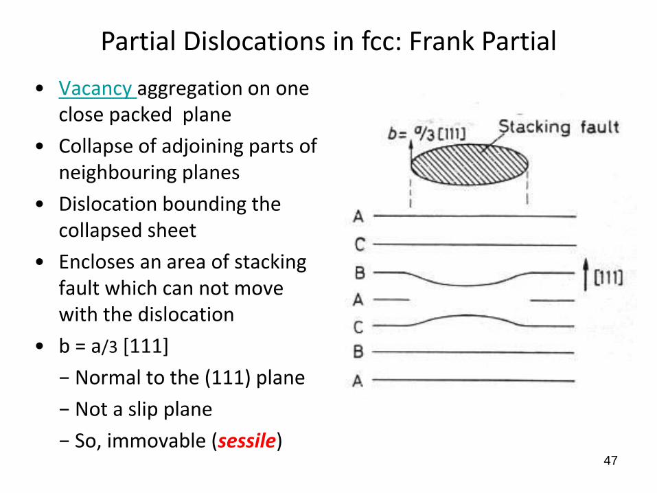
• Vacancy aggregation on one close packed plane
• Collapse of adjoining parts of neighbouring planes
• Dislocation bounding the collapsed sheet
• Encloses an area of stacking fault which can not move with the dislocation
• b = a/3 [111]
− Normal to the (111) plane
− Not a slip plane
− So, immovable (sessile)47
Partial Dislocations in fcc: Frank Partial
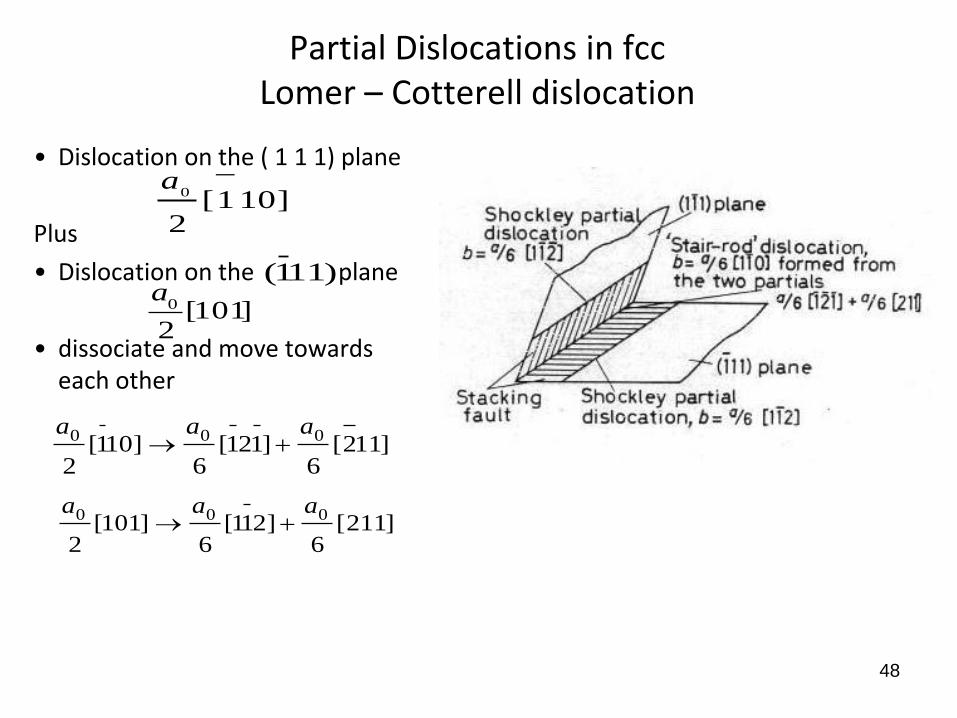
Partial Dislocations in fccLomer – Cotterell dislocation
• Dislocation on the ( 1 1 1) plane
Plus
• Dislocation on the plane
• dissociate and move towards each other
48
]101[2
0a
)111(
]101[2
0
a
]112[6
]121[6
]101[2
000 aaa
]211[6
]211[6
]101[2
000 aaa
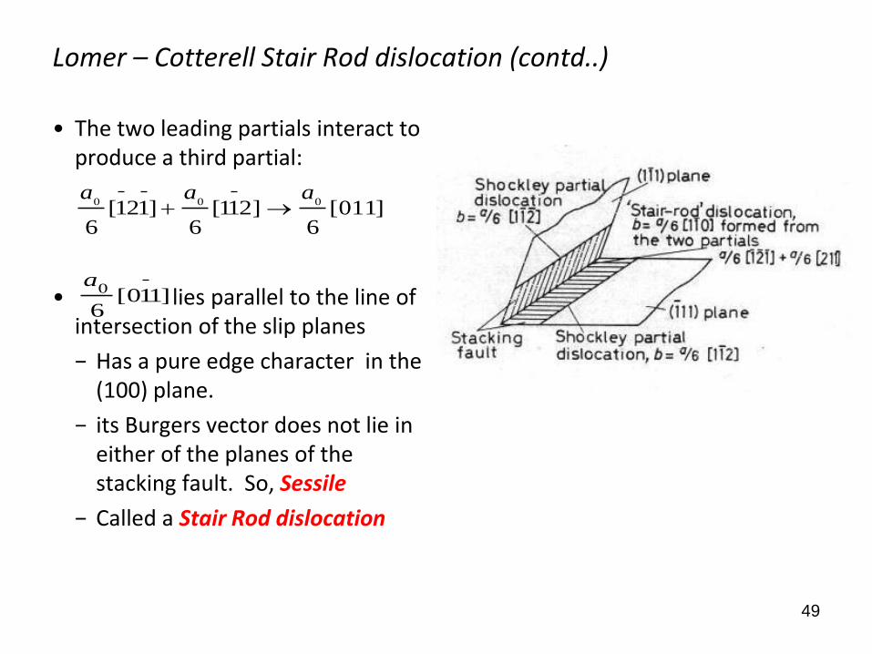
Lomer – Cotterell Stair Rod dislocation (contd..)
• The two leading partials interact to produce a third partial:
• lies parallel to the line of intersection of the slip planes
− Has a pure edge character in the (100) plane.
− its Burgers vector does not lie in either of the planes of the stacking fault. So, Sessile
− Called a Stair Rod dislocation
49
]011[6
]211[6
]121[6
000aaa
]110[6
0a
50
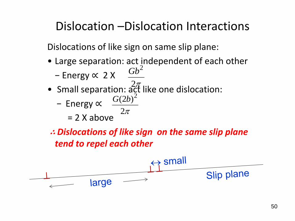
Dislocations of like sign on same slip plane:
• Large separation: act independent of each other
− Energy ∝ 2 X
• Small separation: act like one dislocation:
− Energy ∝
= 2 X above
∴ Dislocations of like sign on the same slip plane tend to repel each other
p2
2Gb
p2
)2( 2bG
Dislocation –Dislocation Interactions
Dislocation –Dislocation Interactions (contd..)
51
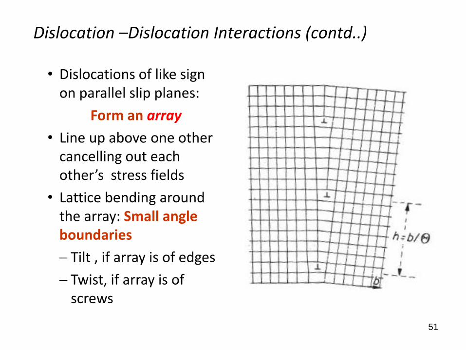
• Dislocations of like sign on parallel slip planes:
Form an array
• Line up above one other cancelling out each other’s stress fields
• Lattice bending around the array: Small angle boundaries
Tilt , if array is of edges
Twist, if array is of screws
52
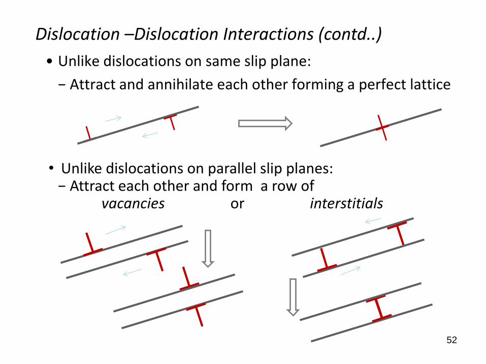
• Unlike dislocations on same slip plane:
− Attract and annihilate each other forming a perfect lattice
Dislocation –Dislocation Interactions (contd..)
• Unlike dislocations on parallel slip planes: − Attract each other and form a row of
vacancies or interstitials
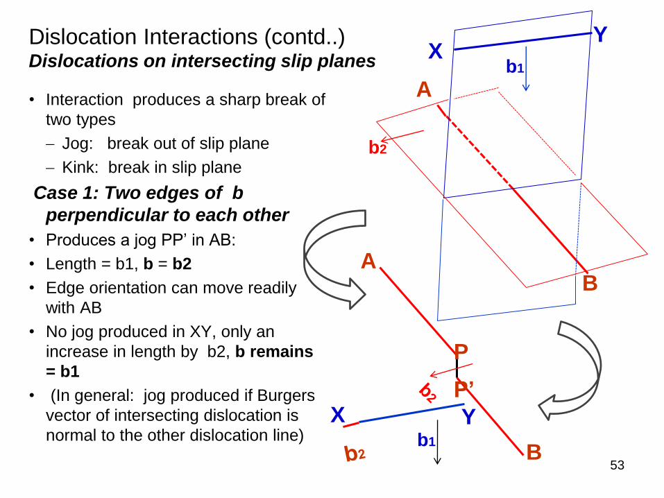
Dislocation Interactions (contd..)Dislocations on intersecting slip planes
• Interaction produces a sharp break of
two types
Jog: break out of slip plane
Kink: break in slip plane
Case 1: Two edges of b
perpendicular to each other
• Produces a jog PP’ in AB:
• Length = b1, b = b2
• Edge orientation can move readily
with AB
• No jog produced in XY, only an
increase in length by b2, b remains
= b1
• (In general: jog produced if Burgers
vector of intersecting dislocation is
normal to the other dislocation line)
53
A
B
P
P’
b1
X Y
b1X
Y
A
B
b2
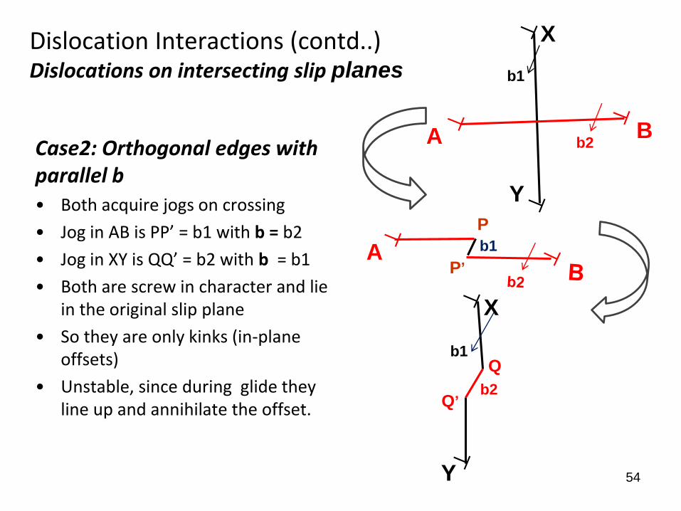
Case2: Orthogonal edges with parallel b • Both acquire jogs on crossing
• Jog in AB is PP’ = b1 with b = b2
• Jog in XY is QQ’ = b2 with b = b1
• Both are screw in character and lie in the original slip plane
• So they are only kinks (in-plane offsets)
• Unstable, since during glide they line up and annihilate the offset.
54
X
Y
BA b2
b1
P
P’A
X
Y
Q
Q’
b1
Dislocation Interactions (contd..)Dislocations on intersecting slip planes
b1
b2
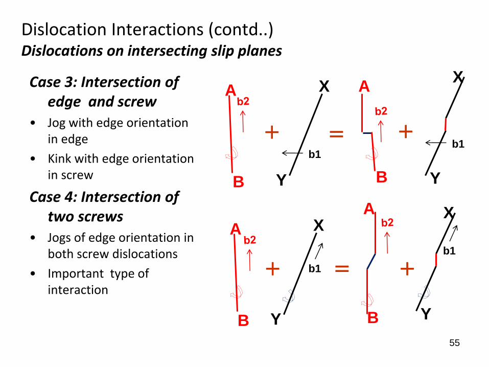
Case 3: Intersection of edge and screw
• Jog with edge orientation in edge
• Kink with edge orientation in screw
Case 4: Intersection of two screws
• Jogs of edge orientation in both screw dislocations
• Important type of interaction
55
Dislocation Interactions (contd..)Dislocations on intersecting slip planes
X
Y
b1
A
B
A
B
X
Y
b1
A
B
X
Y
b1
A
B
X
Y
b1
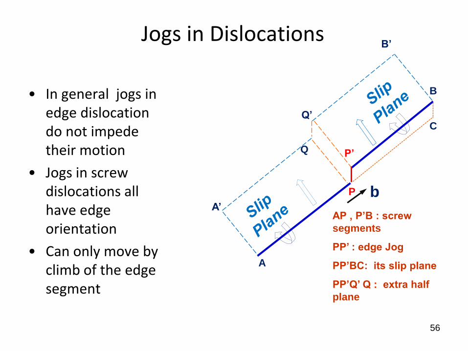
• In general jogs in edge dislocation do not impede their motion
• Jogs in screw dislocations all have edge orientation
• Can only move by climb of the edge segment
56
Jogs in Dislocations
AP , P’B : screw
segments
PP’ : edge Jog
PP’BC: its slip plane
PP’Q’ Q : extra half
plane
b
A
B
P
P’Q
A’
B’
Q’C
Jogs in Dislocations (contd..)
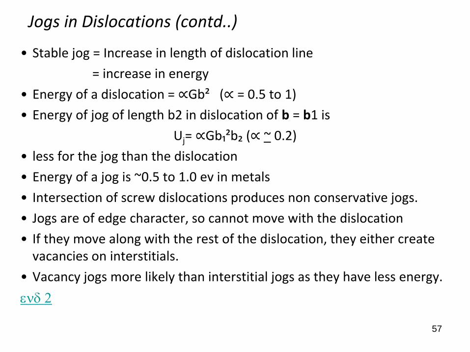
• Stable jog = Increase in length of dislocation line
= increase in energy
• Energy of a dislocation = ∝Gb² (∝ = 0.5 to 1)
• Energy of jog of length b2 in dislocation of b = b1 is
Uj= ∝Gb₁²b₂ (∝ ~ 0.2)
• less for the jog than the dislocation
• Energy of a jog is ~0.5 to 1.0 ev in metals
• Intersection of screw dislocations produces non conservative jogs.
• Jogs are of edge character, so cannot move with the dislocation
• If they move along with the rest of the dislocation, they either create vacancies on interstitials.
• Vacancy jogs more likely than interstitial jogs as they have less energy.
ed 2
57
58
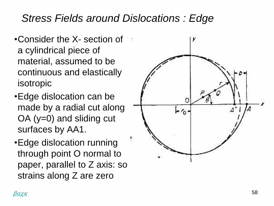
Stress Fields around Dislocations : Edge
•Consider the X- section of
a cylindrical piece of
material, assumed to be
continuous and elastically
isotropic
•Edge dislocation can be
made by a radial cut along
OA (y=0) and sliding cut
surfaces by AA1.
•Edge dislocation running
through point O normal to
paper, parallel to Z axis: so
strains along Z are zero
back
59
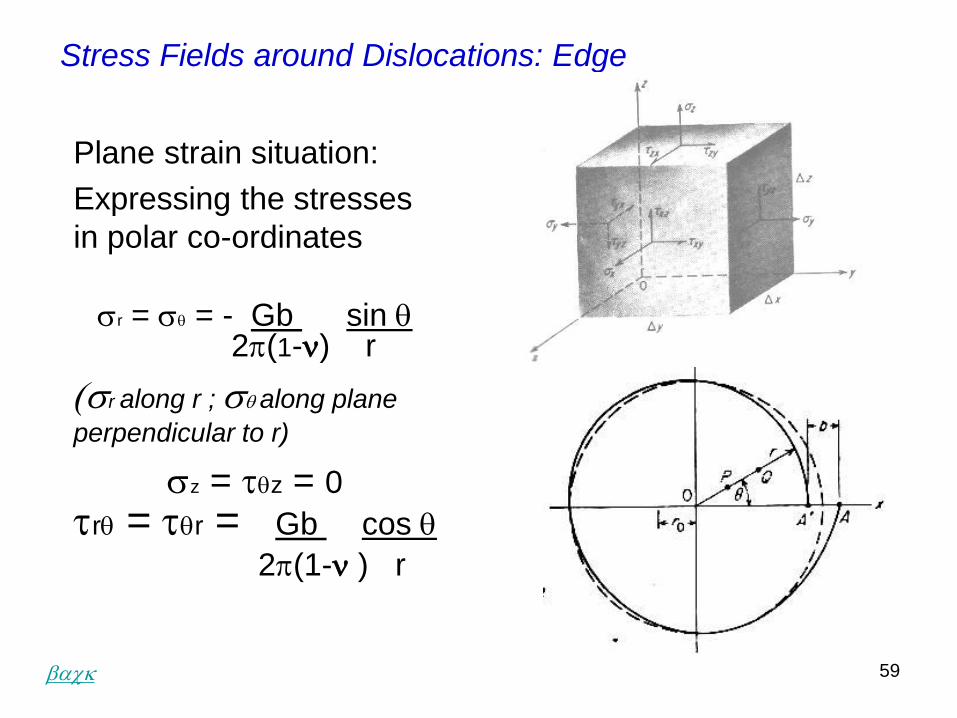
Stress Fields around Dislocations: Edge
Plane strain situation:
Expressing the stresses
in polar co-ordinates
sr = sq = - Gb sin q2p(1-) r
(sr along r ; sq along plane
perpendicular to r)
sz = tqz = 0trq = tqr = Gb cos q
2p(1- ) r
back
60
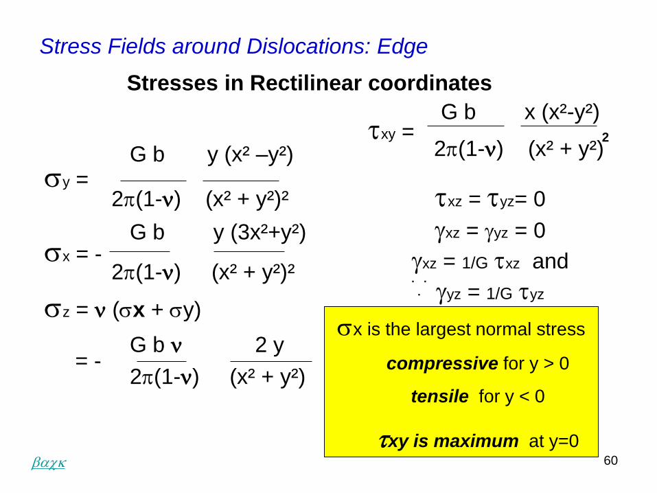
Stress Fields around Dislocations: Edge
G b y (x² –y²)sy =
2p(1-) (x² + y²)²
G b y (3x²+y²)sx = -
2p(1-) (x² + y²)²
sz = (sx + sy)
G b 2 y= -
2p(1-) (x² + y²)
G b x (x²-y²) txy =
2p(1-) (x² + y²)
txz = tyz= 0
gxz = gyz = 0
gxz = 1/G txz and
gyz = 1/G tyz
Stresses in Rectilinear coordinates
2
. .
.
sx is the largest normal stress
compressive for y > 0
tensile for y < 0
txy is maximum at y=0back
61
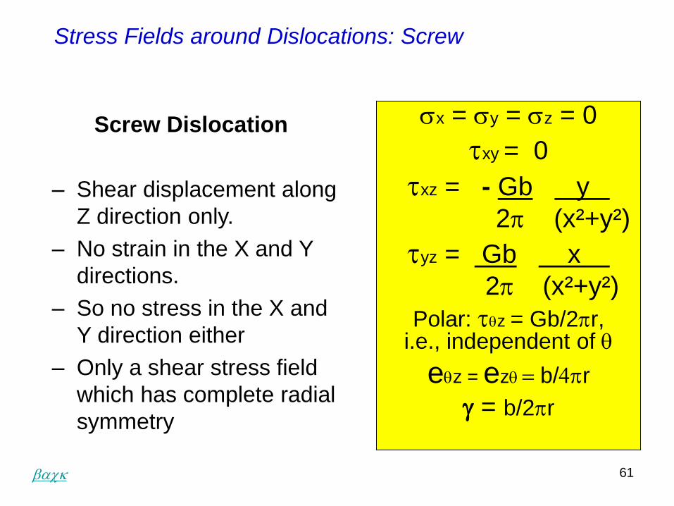
sx = sy = sz = 0
txy = 0
txz = - Gb y
2p (x²+y²)
tyz = Gb x
2p (x²+y²)
Polar: tqz = Gb/2pr, i.e., independent of q
eqz = ezq b/4pr
g = b/2pr
Screw Dislocation
– Shear displacement along
Z direction only.
– No strain in the X and Y
directions.
– So no stress in the X and
Y direction either
– Only a shear stress field
which has complete radial
symmetry
Stress Fields around Dislocations: Screw
back
62
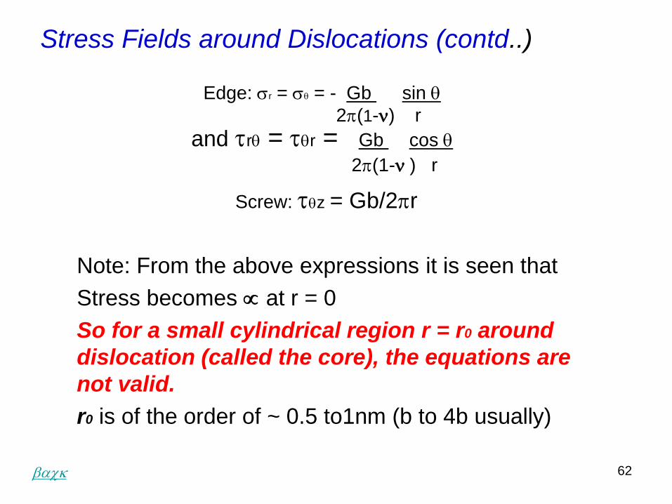
Stress Fields around Dislocations (contd..)
Edge: sr = sq = - Gb sin q
2p(1-) r
and trq = tqr = Gb cos q
2p(1- ) r
Screw: tqz = Gb/2pr
Note: From the above expressions it is seen that
Stress becomes at r = 0
So for a small cylindrical region r = r0 around
dislocation (called the core), the equations are
not valid.
r0 is of the order of ~ 0.5 to1nm (b to 4b usually)
back
63
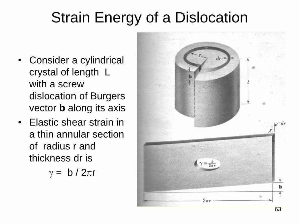
Strain Energy of a Dislocation
• Consider a cylindrical
crystal of length L
with a screw
dislocation of Burgers
vector b along its axis
• Elastic shear strain in
a thin annular section
of radius r and
thickness dr is
g = b / 2pr
64
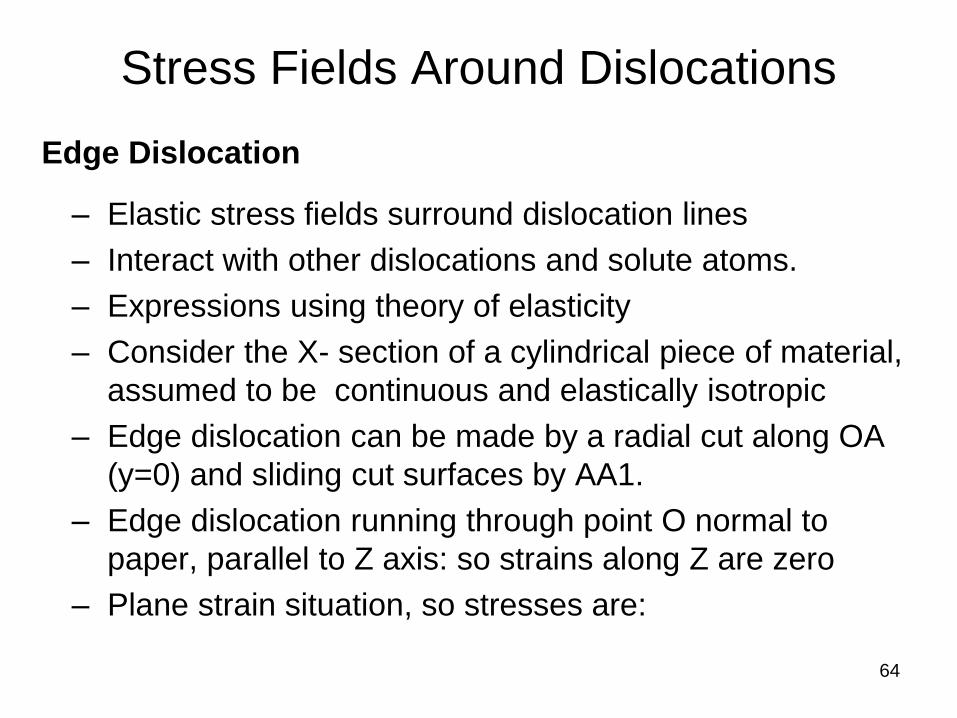
Stress Fields Around Dislocations
Edge Dislocation
– Elastic stress fields surround dislocation lines
– Interact with other dislocations and solute atoms.
– Expressions using theory of elasticity
– Consider the X- section of a cylindrical piece of material,
assumed to be continuous and elastically isotropic
– Edge dislocation can be made by a radial cut along OA
(y=0) and sliding cut surfaces by AA1.
– Edge dislocation running through point O normal to
paper, parallel to Z axis: so strains along Z are zero
– Plane strain situation, so stresses are:
65
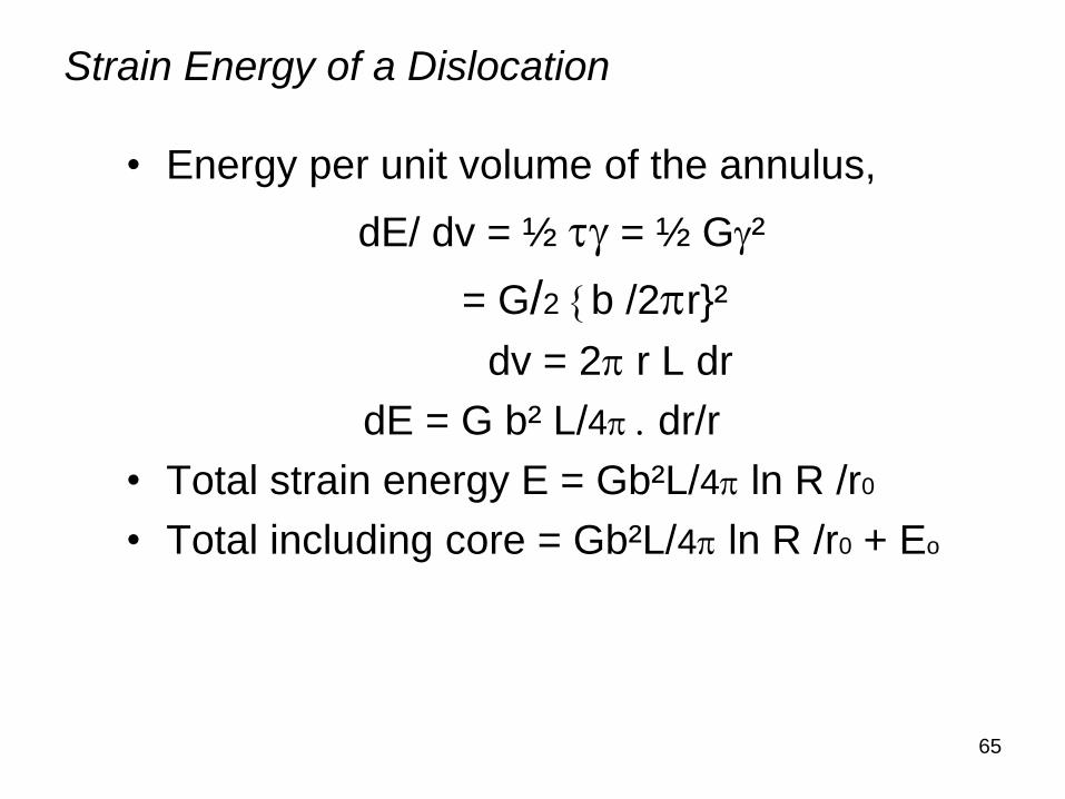
Strain Energy of a Dislocation
• Energy per unit volume of the annulus,
dE/ dv = ½ tg = ½ Gg²
= G/2 b /2pr}²
dv = 2p r L dr
dE = G b² L/4p . dr/r
• Total strain energy E = Gb²L/4p ln R /r0
• Total including core = Gb²L/4p ln R /r0 + Eo
66
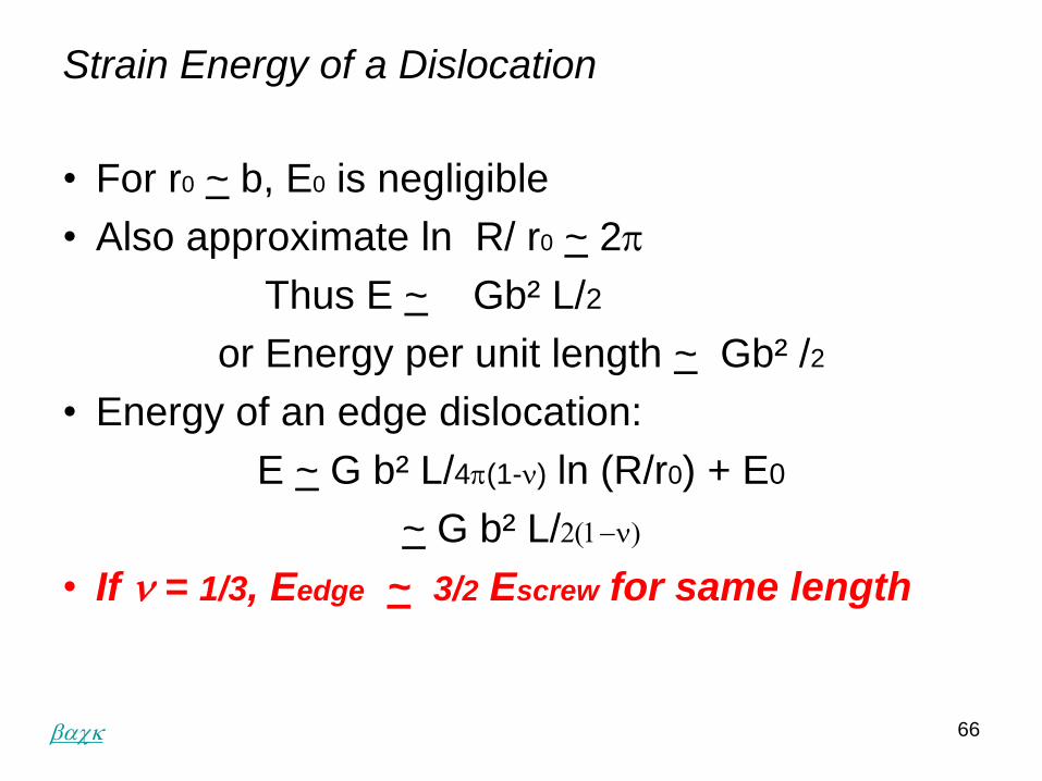
• For r0 ~ b, E0 is negligible
• Also approximate ln R/ r0 ~ 2p
Thus E ~ Gb² L/2
or Energy per unit length ~ Gb² /2
• Energy of an edge dislocation:
E ~ G b² L/4p(1-) ln (R/r0) + E0
~ G b² L/2(1)
• If = 1/3, Eedge ~ 3/2 Escrew for same length
Strain Energy of a Dislocation
back
67
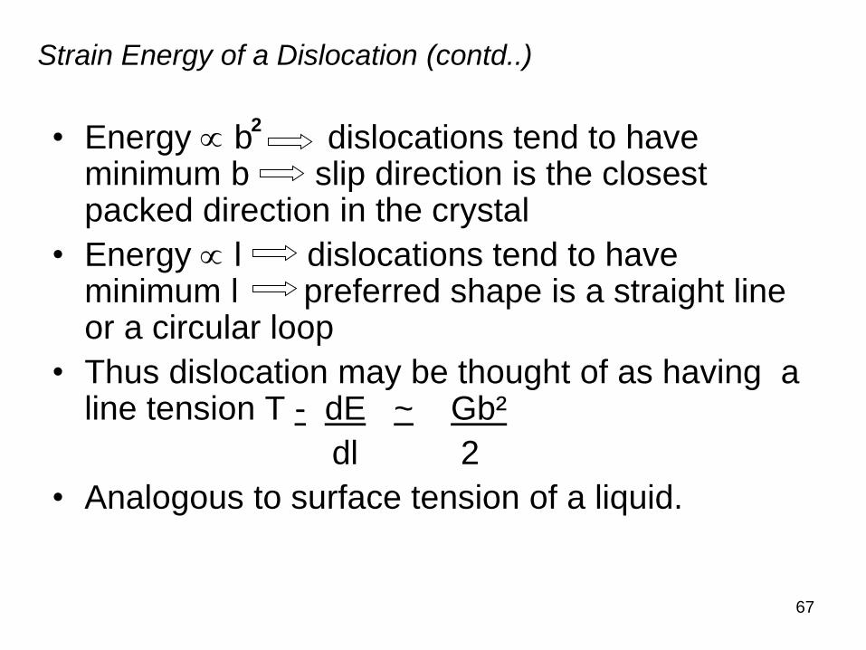
Strain Energy of a Dislocation (contd..)
• Energy b dislocations tend to have minimum b slip direction is the closest packed direction in the crystal
• Energy l dislocations tend to have minimum l preferred shape is a straight line or a circular loop
• Thus dislocation may be thought of as having a line tension T - dE ~ Gb²
dl 2
• Analogous to surface tension of a liquid.
2
68
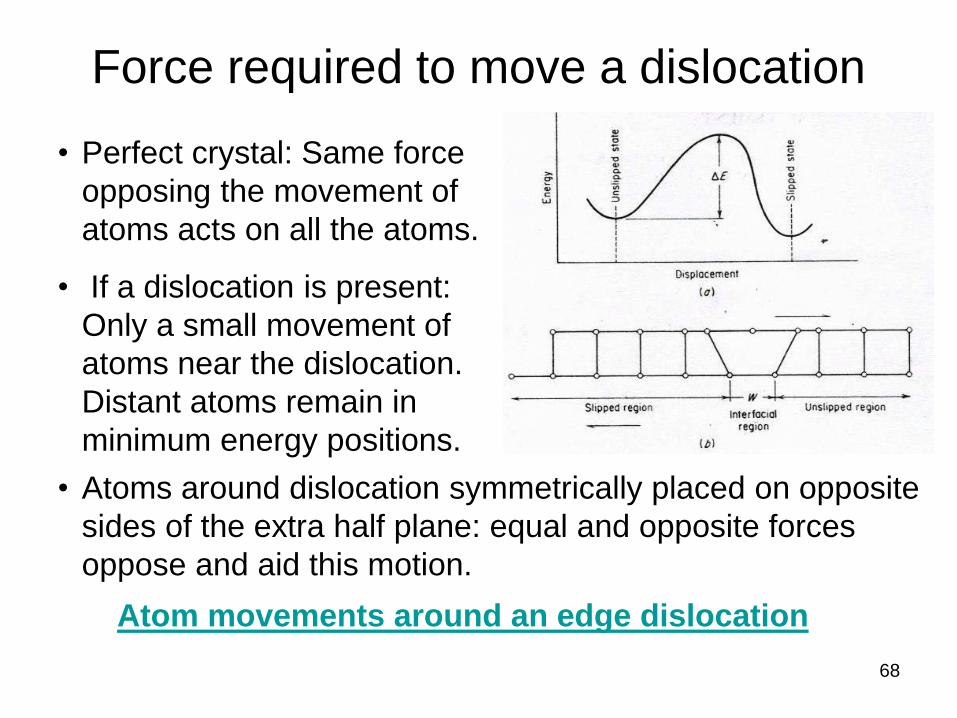
Force required to move a dislocation
• Perfect crystal: Same force
opposing the movement of
atoms acts on all the atoms.
• If a dislocation is present:
Only a small movement of
atoms near the dislocation.
Distant atoms remain in
minimum energy positions.
• Atoms around dislocation symmetrically placed on opposite
sides of the extra half plane: equal and opposite forces
oppose and aid this motion.
Atom movements around an edge dislocation
69
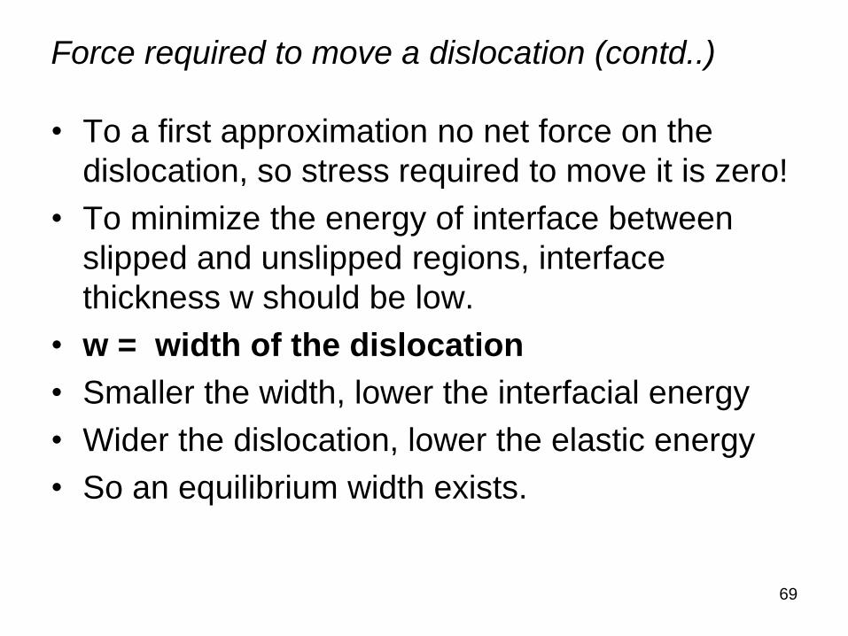
Force required to move a dislocation (contd..)
• To a first approximation no net force on the
dislocation, so stress required to move it is zero!
• To minimize the energy of interface between
slipped and unslipped regions, interface
thickness w should be low.
• w = width of the dislocation
• Smaller the width, lower the interfacial energy
• Wider the dislocation, lower the elastic energy
• So an equilibrium width exists.
70
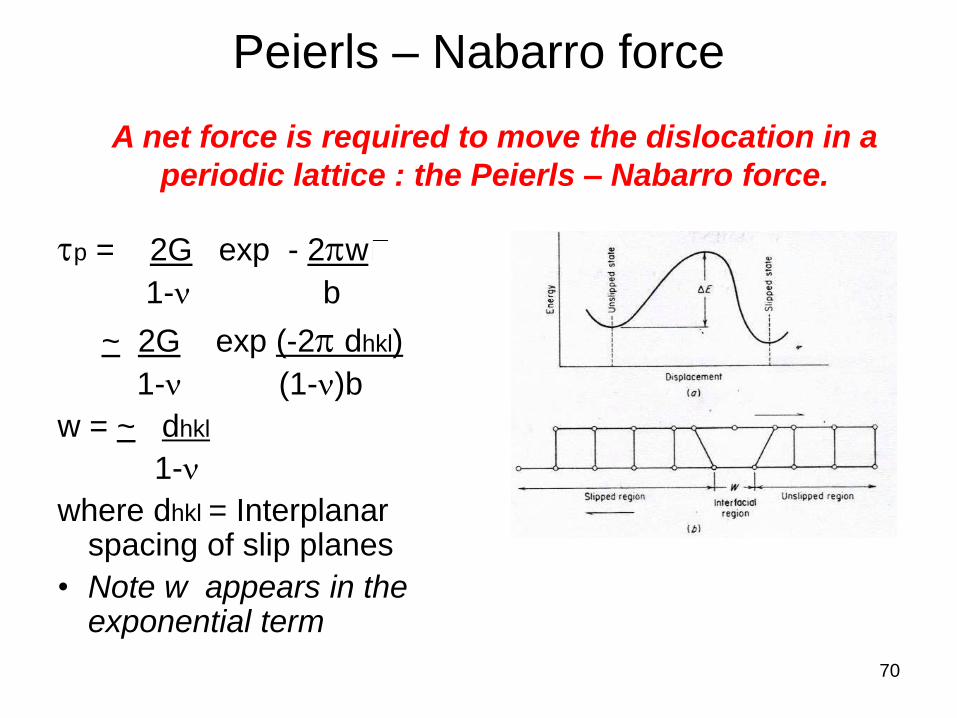
Peierls – Nabarro force
tp = 2G exp - 2pw
1- b
~ 2G exp (-2p dhkl)
1- (1-)b
w = ~ dhkl
1-
where dhkl = Interplanar spacing of slip planes
• Note w appears in the exponential term
A net force is required to move the dislocation in a
periodic lattice : the Peierls – Nabarro force.
71
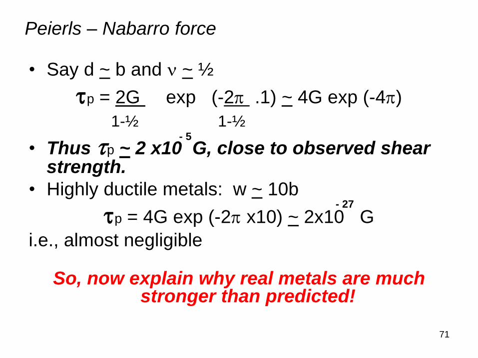
• Say d ~ b and ~ ½
tp = 2G exp (-2p .1) ~ 4G exp (-4p)
1-½ 1-½
• Thus tp ~ 2 x10 G, close to observed shear strength.
• Highly ductile metals: w ~ 10b
tp = 4G exp (-2p x10) ~ 2x10 G
i.e., almost negligible
So, now explain why real metals are much stronger than predicted!
- 27
- 5
Peierls – Nabarro force
72
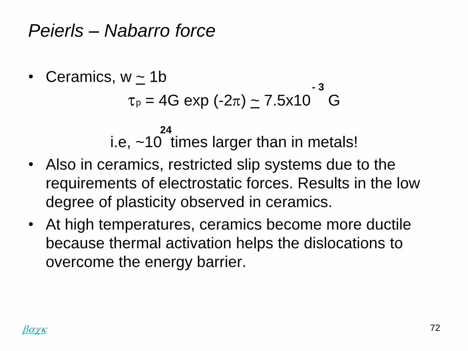
Peierls – Nabarro force
• Ceramics, w ~ 1b
tp = 4G exp (-2p) ~ 7.5x10 G
i.e, ~10 times larger than in metals!
• Also in ceramics, restricted slip systems due to the
requirements of electrostatic forces. Results in the low
degree of plasticity observed in ceramics.
• At high temperatures, ceramics become more ductile
because thermal activation helps the dislocations to
overcome the energy barrier.
- 3
24
back
73
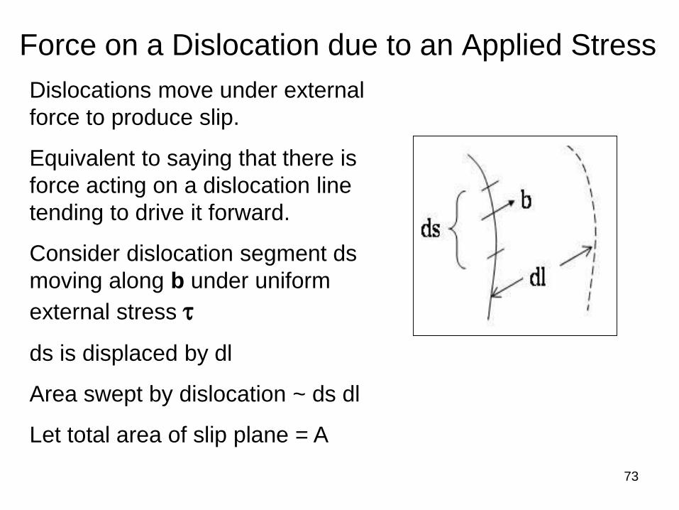
Force on a Dislocation due to an Applied Stress
Dislocations move under external
force to produce slip.
Equivalent to saying that there is
force acting on a dislocation line
tending to drive it forward.
Consider dislocation segment ds
moving along b under uniform
external stress t
ds is displaced by dl
Area swept by dislocation ~ ds dl
Let total area of slip plane = A
74
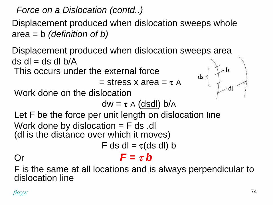
Force on a Dislocation (contd..)
This occurs under the external force
= stress x area = t A
Work done on the dislocation
dw = t A (dsdl) b/A
Let F be the force per unit length on dislocation line
Work done by dislocation = F ds .dl (dl is the distance over which it moves)
F ds dl = t(ds dl) b
Or F = t bF is the same at all locations and is always perpendicular to dislocation line
Displacement produced when dislocation sweeps whole
area = b (definition of b)
Displacement produced when dislocation sweeps area
ds dl = ds dl b/A
back
75
dq/2
T
T
dq/2
T Sin dq/2
T Sin dq/2
F = t b dS
Force required to bend a dislocation
back
76
Force required to bend a
dislocation
• Line tension T will tend to straighten the
dislocation line.
• Dislocation can only remain curved if the
shear stresses produce a force sufficient
to resist the line tension.
• Let the dislocation be bent to a radius of
curvature R
• Shear stress required to maintain it at
this radius can be estimated as follows
77
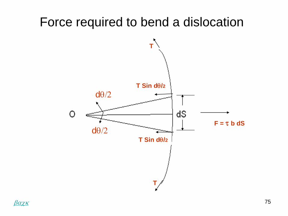
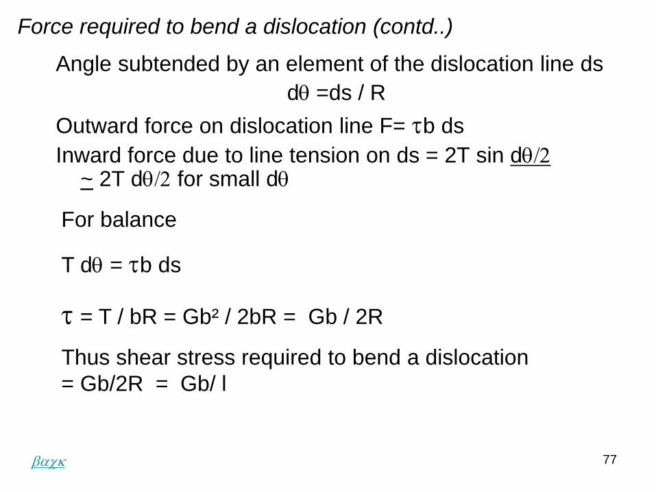
Angle subtended by an element of the dislocation line ds
dq =ds / R
Outward force on dislocation line F= tb ds
Inward force due to line tension on ds = 2T sin dq/2~ 2T dq/2 for small dq
Force required to bend a dislocation (contd..)
For balance
T dq = tb ds
t = T / bR = Gb² / 2bR = Gb / 2R
Thus shear stress required to bend a dislocation
= Gb/2R = Gb/ l
back
78
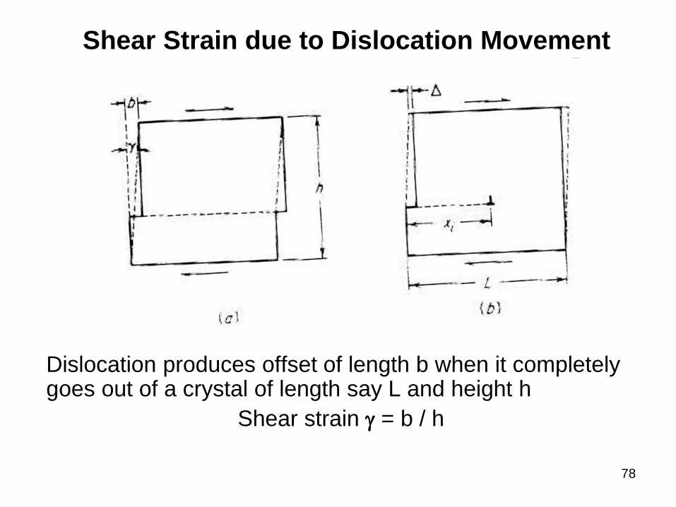
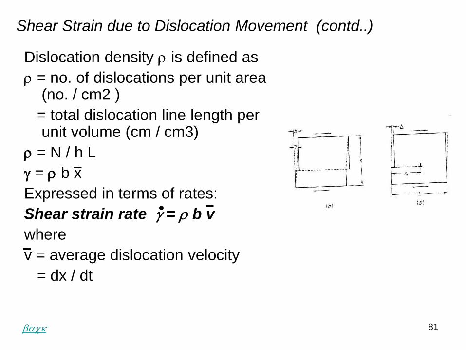
Shear Strain due to Dislocation Movement
Dislocation produces offset of length b when it completely goes out of a crystal of length say L and height h
Shear strain g = b / h
79
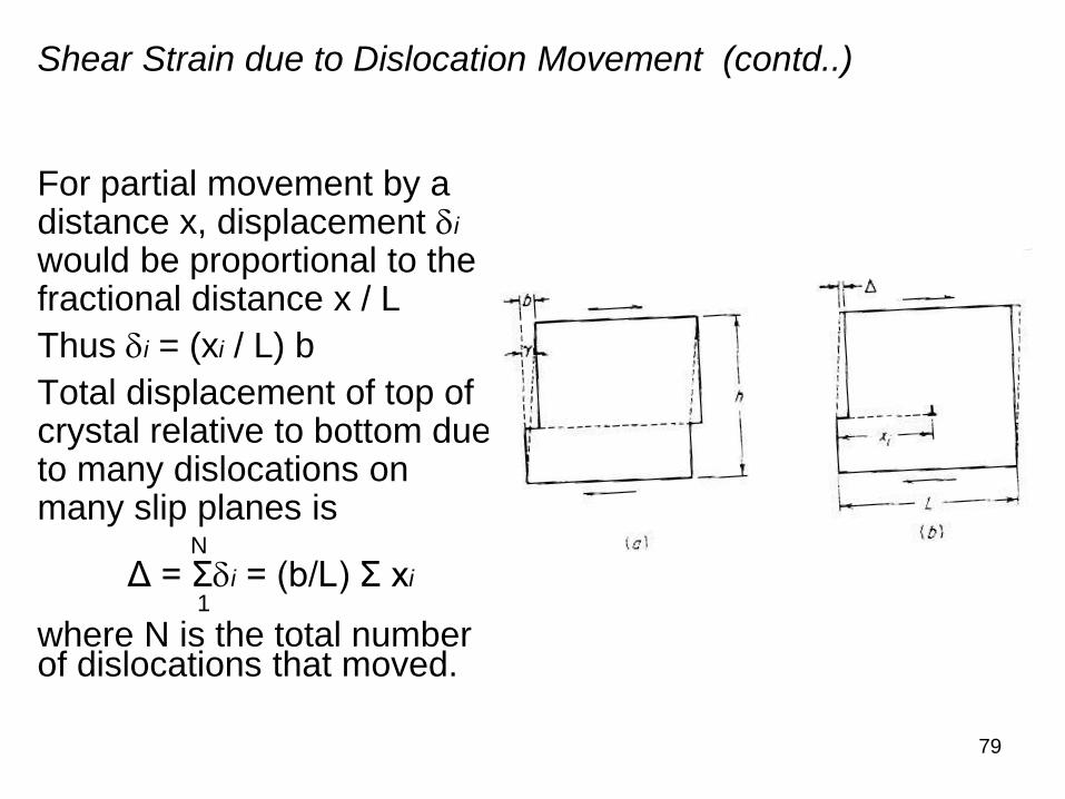
For partial movement by a distance x, displacement di
would be proportional to the fractional distance x / L
Thus di = (xi / L) b
Total displacement of top of crystal relative to bottom due to many dislocations on many slip planes is
N
Δ = Σdi = (b/L) Σ xi1
where N is the total number of dislocations that moved.
Shear Strain due to Dislocation Movement (contd..)
80
Shear Strain due to Dislocation Movement (contd..)
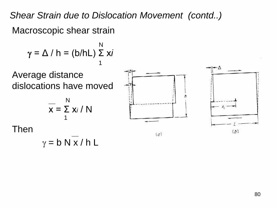
Macroscopic shear strain
N
g = Δ / h = (b/hL) Σ xi1
Average distance
dislocations have moved
N
x = Σ xi / N1
Then
g = b N x / h L
81
Dislocation density r is defined as
r = no. of dislocations per unit area (no. / cm2 )
= total dislocation line length per unit volume (cm / cm3)
r = N / h L
g = r b x
Expressed in terms of rates:
Shear strain rate g = r b v
where
v = average dislocation velocity
= dx / dt
Shear Strain due to Dislocation Movement (contd..)
back
82
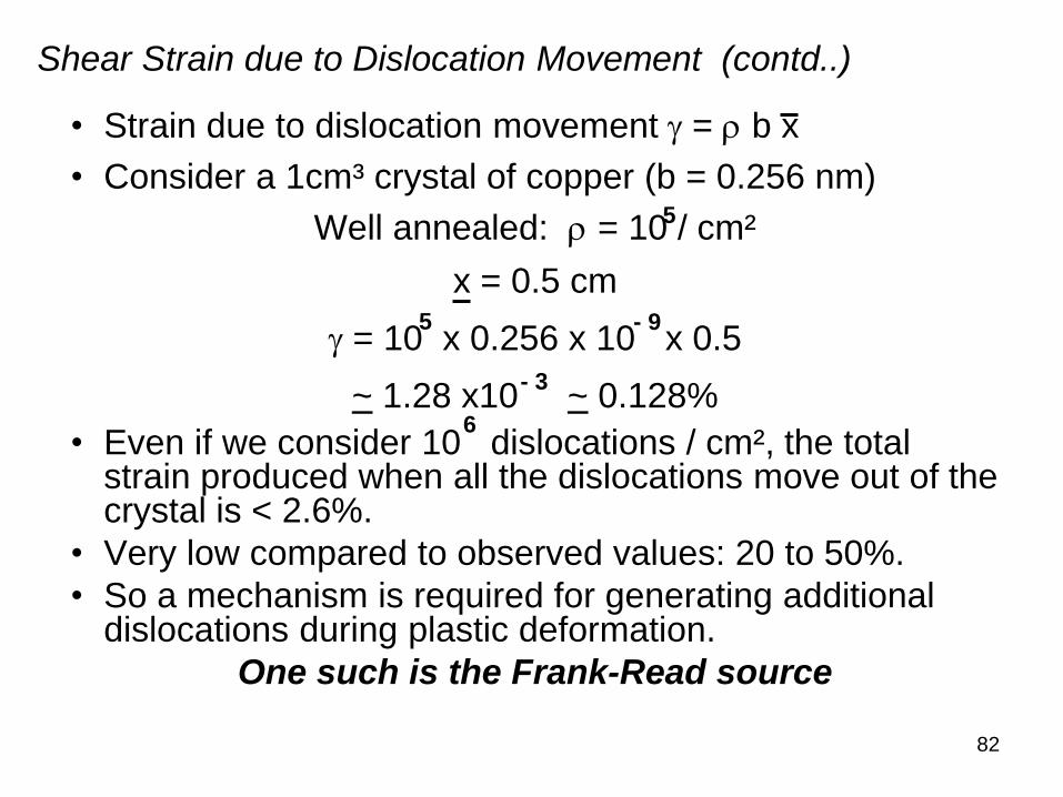
• Strain due to dislocation movement g = r b x
• Consider a 1cm³ crystal of copper (b = 0.256 nm)
Well annealed: r = 10 / cm²
x = 0.5 cm
g = 10 x 0.256 x 10 x 0.5
~ 1.28 x10 ~ 0.128%
• Even if we consider 10 dislocations / cm², the total strain produced when all the dislocations move out of the crystal is < 2.6%.
• Very low compared to observed values: 20 to 50%.
• So a mechanism is required for generating additional dislocations during plastic deformation.
One such is the Frank-Read source
- 9
5
6
5
- 3
Shear Strain due to Dislocation Movement (contd..)
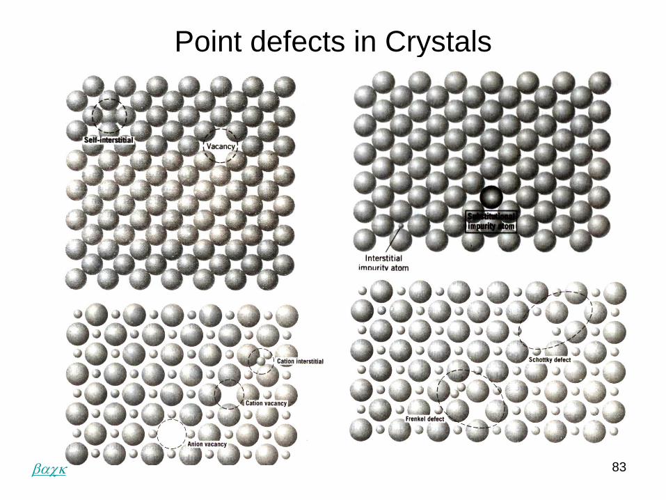
Point defects in Crystals
83back
Elementary Dislocation Theory
End of Lecture 2