PLASMA CUTTING SYSTEM - Cigweld€¦ · PLASMA CUTTING SYSTEM 10mm 12mm CUTMASTER™ ... you on the...
44
30 20 40 Art A-10399 30 AMP 40 AMP 1 DC PHASE 240 PLASMA CUTTING SYSTEM 10mm 12mm CUTMASTER ™ Rev. AD Date: February 10, 2012 Manual # 0-5197AD Operating Features: Operating Manual
-
Upload
hoangthien -
Category
Documents
-
view
213 -
download
0
Transcript of PLASMA CUTTING SYSTEM - Cigweld€¦ · PLASMA CUTTING SYSTEM 10mm 12mm CUTMASTER™ ... you on the...

30
20 40
Art A-10399
30AMP
40AMP
1DC PHASE240
PLASMA CUTTING SYSTEM
10mm 12mm CUTMASTER™
Rev. AD Date: February 10, 2012 Manual # 0-5197AD Operating Features:
Operating Manual

WE APPRECIATE YOUR BUSINESS!Congratulations on your new Thermal Dynamics product. We are proud to have you as our customer and will strive to provide you with the best service and reliability in the industry. This product is backed by our extensive warranty and world-wide service network. To locate your nearest distributor or service provider visit us at www.thermadyne.com on the web.
This Installation/Operating Manual has been designed to instruct you on the correct use and operation of your Thermal Dynamics product. Your satisfaction with this product and its safe operation is our ultimate concern. Therefore please take the time to read the entire manual, especially the Safety Precautions. They will help you to avoid potential hazards that may exist when working with this product.
YOU ARE IN GOOD COMPANY!The Brand of Choice for Contractors and Fabricators Worldwide.Thermal Dynamics is a Global Brand of manual and automation Plasma Cutting Products for Thermadyne Industries Inc.
We distinguish ourselves from our competition through market-leading, dependable products that have stood the test of time. We pride ourselves on technical innovation, competitive prices, excellent delivery, superior customer service and technical support, together with excellence in sales and marketing expertise.
Above all, we are committed to developing technologically advanced products to achieve a safer working environment within the welding industry.

! WARNINGS
Read and understand this entire Operating Manual and your employer’s safety practices before installing, operating, or servicing the equipment.
While the information contained in this Manual represents the Manufacturer's best judgement, the Manufacturer assumes no liability for its use.
Plasma Cutting Power SourceCutMaster™ 10mm Plant - Part Number 1-4730-6Cutmaster™ 12mm Plant - Part Number 1-4200-6 SL60 Torch™Operating Manual Number 0-5197AC
Published by:Thermal Dynamics Corporation82 Benning StreetWest Lebanon, New Hampshire, USA 03784(603) 298-5711
www.thermadyne.com
Copyright 2011, 2012 byThermadyne Corporation
All rights reserved.
Reproduction of this work, in whole or in part, without written permission of the publisher is prohibited.
The publisher does not assume and hereby disclaims any liability to any party for any loss or damage caused by any error or omission in this Manual, whether such error results from negli-gence, accident, or any other cause.
Publication Date: July 1, 2011Revision AD Date: February 10, 2012
Record the following information for Warranty purposes:
Where Purchased:_______________________________ __________________
Purchase Date:__________________________________ __________________
Power Source Serial #:___________________________ ___________________
Torch Serial #:___________________________________ _________________
i

TABLE OF CONTENTSSECTION 1: GENERAL INFORMATION .............................................................................1-1
1.01 Notes, Cautions and Warnings ................................................................................. 1-11.02 Important Safety Precautions ................................................................................... 1-11.03 Publications .............................................................................................................. 1-41.04 Declaration of Conformity......................................................................................... 1-5
SECTION 2 SYSTEM: INTRODUCTION .............................................................................2-1
2.01 How To Use This Manual .......................................................................................... 2-12.02 Equipment Identification ........................................................................................... 2-12.03 Receipt Of Equipment ............................................................................................... 2-12.04 Working Principle ..................................................................................................... 2-12.05 Power Source Specifications .................................................................................... 2-22.06 Input Wiring Specifications ...................................................................................... 2-42.07 Power Source Feature Locations .............................................................................. 2-5
SECTION 2 TORCH: INTRODUCTION............................................................................. 2T-1
2T.01 Scope of Operating Manual .................................................................................... 2T-12T.02 Specifications ........................................................................................................ 2T-12T.03 Introduction to Plasma ........................................................................................... 2T-2
SECTION 3: INSTALLATION .........................................................................................3-1
3.01 Unpacking ................................................................................................................ 3-13.02 Lifting Options .......................................................................................................... 3-13.03 Air Supply Connections ............................................................................................ 3-2
SECTION 4 SYSTEM: OPERATION ..................................................................................4-1
4.01 Control Panel ............................................................................................................ 4-14.02 Preparations for Operating ....................................................................................... 4-24.03 Sequence of Operation ............................................................................................. 4-44.04 Cut Quality ................................................................................................................ 4-64.05 General Cutting Information ..................................................................................... 4-7
SECTION 5 SYSTEM: SERVICE .....................................................................................5-1
5.01 General Maintenance ................................................................................................ 5-15.02 Basic Troubleshooting Guide .................................................................................... 5-2
SECTION 5 TORCH: SERVICE ..................................................................................... 5T-1
5T.01 General Maintenance .............................................................................................. 5T-15T.02 Inspection and Replacement of Consumable Torch Parts ....................................... 5T-2
SECTION 6: PARTS LIST .............................................................................................6-1
6.01 Introduction .............................................................................................................. 6-16.02 Power Source Replacement Parts ............................................................................ 6-16.03 SL60 Replacement Parts .......................................................................................... 6-26.04 Options and Accessories .......................................................................................... 6-2
APPENDIX 1: CIRCUIT DIAGRAM ..................................................................................A-1
Statement of Warranty ............................................................................ Inside Back Cover
GLOBAL CUSTOMER SERVICE CONTACT INFORMATION ..................................... Inside Back Cover

Figures and Tables
SECTION 1: GENERAL INFORMATION .............................................................................1-1
Table 1-1 - Protective Filters .................................................................................................... 1-3
SECTION 2 SYSTEM: INTRODUCTION .............................................................................2-1
Figure 2-1 - Power Source Dimensions & Weight.................................................................... 2-3Figure 2-2 - Power Source Setup ............................................................................................. 2-5Figure 2-3 - Power Source Rear View ...................................................................................... 2-5
SECTION 2 TORCH: INTRODUCTION............................................................................. 2T-1
Figure 2T-1 - SL60 Torch ....................................................................................................... 2T-1Figure 2T-2 - Typical Torch Head Detail .................................................................................. 2T-2Figure 2T-3 - Parts-in-Place Circuit Diagram for Hand Torch ................................................. 2T-2
SECTION 3: INSTALLATION .........................................................................................3-1
Figure 3-1 - Gas Connection to Compressed Air Input ............................................................ 3-2Figure 3-2 - Optional Single - Stage Filter Installation for Compressed Air Input .................... 3-2
SECTION 4 SYSTEM: OPERATION ..................................................................................4-1
Figure 4-1 - Front Control Panel .............................................................................................. 4-1Figure 4-2 - Rear Controls ....................................................................................................... 4-1Figure 4-3 - SL60 Torch Parts .................................................................................................. 4-2Figure 4-4 - Work Cable Connection ........................................................................................ 4-3Figure 4-5 - Rear Panel with ON/OFF Switch ............................................................................ 4-3Figure 4-6 - Front Panel with Power ON/OFF Indicator ............................................................ 4-3Figure 4-7 - Torch Trigger Release ........................................................................................... 4-4Figure 4-8 - Standoff Distance ................................................................................................. 4-4Figure 4-9 - Standoff Cutting ................................................................................................... 4-4Figure 4-10 - Torch Trigger Release ......................................................................................... 4-5Figure 4-11 - Drag Cutting ....................................................................................................... 4-5Figure 4-12 - Cut Quality Characteristics ................................................................................. 4-6Figure 4-13 - Side Characteristics of Cut ................................................................................. 4-7
SECTION 5 TORCH: SERVICE ..................................................................................... 5T-1
Figure 5-1 - Torch Head O-Ring ............................................................................................. 5T-1Figure 5-2 - ATC O-Ring ......................................................................................................... 5T-1Figure 5-3 - Consumable Parts ............................................................................................. 5T-2Figure 5-4 - Tip Wear ............................................................................................................. 5T-2Figure 5-5 - Start Cartridge .................................................................................................... 5T-2Figure 5-6 - Electrode Wear ................................................................................................... 5T-2
SECTION 6: PARTS LIST .............................................................................................6-1
Parts 6-1 - Power Source ........................................................................................................ 6-1Parts 6-2 - Electrode Parts ....................................................................................................... 6-2
APPENDIX 1: CIRCUIT DIAGRAM ..................................................................................A-1
Figure 1 - Appendix: Circuit Diagram .......................................................................................A-1

This Page Intentionally Blank
CUTMASTER 10MM, 12MM
Manual 0-5197AD 1-1 GENERAL INFORMATION
1.01 Notes, Cautions and WarningsThroughout this manual, notes, cautions, and warnings are used to highlight important information. These highlights are categorized as follows:
NOTE
An operation, procedure, or background information which requires additional emphasis or is helpful in ef-ficient operation of the system.
CAUTION
A procedure which, if not properly followed, may cause damage to the equipment.
! WARNING
A procedure which, if not properly followed, may cause injury to the operator or others in the operating area.
1.02 Important Safety Precautions
! WARNING
OPERATION AND MAINTENANCE OF PLASMA ARC EQUIPMENT CAN BE DANGEROUS AND HAZARDOUS TO YOUR HEALTH.
Plasma arc cutting produces intense electric and magnetic emissions that may interfere with the proper function of cardiac pacemakers, hearing aids, or other electronic health equipment. Persons who work near plasma arc cutting applications should consult their medical health professional and the manufacturer of the health equipment to determine whether a hazard exists.
To prevent possible injury, read, understand and follow all warnings, safety precautions and instructions before using the equipment. Call 1-603-298-5711 or your local distributor if you have any questions.
GASES AND FUMESGases and fumes produced during the plasma cutting process can be dangerous and hazardous to your health.
• Keepallfumesandgasesfromthebreathingarea.Keepyourhead out of the welding fume plume.
• Useanair-suppliedrespiratorifventilationisnotadequatetoremove all fumes and gases.
• Thekindsoffumesandgasesfromtheplasmaarcdependonthe kind of metal being used, coatings on the metal, and the different processes. You must be very careful when cutting or welding any metals which may contain one or more of the following:
Antimony Chromium Mercury Arsenic Cobalt Nickel Barium Copper Selenium Beryllium Lead Silver Cadmium Manganese Vanadium
• AlwaysreadtheMaterialSafetyDataSheets(MSDS)thatshouldbe supplied with the material you are using. These MSDSs will give you the information regarding the kind and amount of fumes and gases that may be dangerous to your health.
• For informationonhowtotest for fumesandgases inyourworkplace, refer to item 1 in Subsection 1.03, Publications in this manual.
• Usespecialequipment,suchaswaterordowndraftcuttingtables, to capture fumes and gases.
• Donotusetheplasmatorchinanareawherecombustibleorexplosive gases or materials are located.
• Phosgene,atoxicgas,isgeneratedfromthevaporsofchlo-rinated solvents and cleansers. Remove all sources of these vapors.
• This product,when used forwelding or cutting, producesfumes or gases which contain chemicals known to the State of California to cause birth defects and, in some cases, cancer. (California Health & Safety Code Sec. 25249.5 et seq.)
SECTION 1: GENERAL INFORMATION
! WARNING
PROTECTYOURSELFANDOTHERSFROMPOSSIBLESERIOUSINJURYORDEATH.KEEPCHILDRENAWAY.PACEMAKERWEAR-ERSKEEPAWAYUNTILCONSULTINGYOURDOCTOR.DONOTLOSETHESEINSTRUCTIONS.READOPERATING/INSTRUCTIONMANUAL BEFORE INSTALLING, OPERATING OR SERVICING THIS EQUIPMENT.Welding products and welding processes can cause serious injury or death, or damage to other equipment or property, if the operator does not strictly observe all safety rules and take precautionary actions.Safe practices have developed from past experience in the use of welding and cutting. These practices must be learned through study and training before using this equipment. Some of these practices apply to equipment connected to power lines; other practices apply to engine driven equipment. Anyone not having extensive training in welding and cutting practices should not attempt to weld.Safe practices are outlined in the Australian Standard AS1674.2-2007 entitled: Safety in welding and allied processes Part 2: Electrical. This publication and other guides to what you should learn before operating this equipment are listed at the end of thesesafetyprecautions.HAVEALLINSTALLATION,OPERATION,MAINTENANCE,ANDREPAIRWORKPERFORMEDONLYBYQUALIFIED PEOPLE.
CUTMASTER 10MM, 12MM
GENERAL INFORMATION 1-2 Manual 0-5197AD
ELECTRIC SHOCKElectric Shock can injure or kill. The plasma arc process uses and produces high voltage electrical energy. This electric energy can cause severe or fatal shock to the operator or others in the workplace.
• Nevertouchanypartsthatareelectrically“live”or“hot.”
• Wear dry gloves and clothing. Insulate yourself from theworkpiece or other parts of the welding circuit.
• Repairorreplaceallwornordamagedparts.
• Extracaremustbetakenwhentheworkplaceismoistordamp.
• InstallandmaintainequipmentaccordingtoNECcode,refertoitem 9 in Subsection 1.03, Publications on page 1-4.
• Disconnect power source before performing any service orrepairs.
• ReadandfollowalltheinstructionsintheOperatingManual.
FIRE AND EXPLOSIONFire and explosion can be caused by hot slag, sparks, or the plasma arc.
• Besurethereisnocombustibleorflammablematerialintheworkplace. Any material that cannot be removed must be protected.
• Ventilateallflammableorexplosivevaporsfromtheworkplace.
• Donotcutorweldoncontainersthatmayhaveheldcombus-tibles.
• Provideafirewatchwhenworkinginanareawherefirehazardsmay exist.
• Hydrogengasmaybe formedand trappedunderaluminumworkpieces when they are cut underwater or while using a water table. DO NOT cut aluminum alloys underwater or on a water table unless the hydrogen gas can be eliminated or dissipated. Trapped hydrogen gas that is ignited will cause an explosion.
NOISENoise can cause permanent hearing loss. Plasma arc processes can cause noise levels to exceed safe limits. You must protect your ears from loud noise to prevent permanent loss of hearing.
• Toprotectyourhearingfromloudnoise,wearprotectiveearplugs and/or ear muffs. Protect others in the workplace.
• Noiselevelsshouldbemeasuredtobesurethedecibels(sound)do not exceed safe levels.
• Forinformationonhowtotestfornoise,seeitem1inSubsec-tion 1.03, Publications, in this manual.
PLASMA ARC RAYSPlasma Arc Rays can injure your eyes and burn your skin. The plasma arc process produces very bright ultra violet and infrared light. These arc rays will damage your eyes and burn your skin if you are not properly protected.
• To protect your eyes, always wear a welding helmet or shield. Also always wear safety glasses with side shields, goggles or other protective eye wear.
• Wear welding gloves and suitable clothing to protect your skin from the arc rays and sparks.
• Keephelmetandsafetyglassesingoodcondition.Replacelenses when cracked, chipped or dirty.
• Protect others in the work area from the arc rays. Use protective booths, screens or shields.
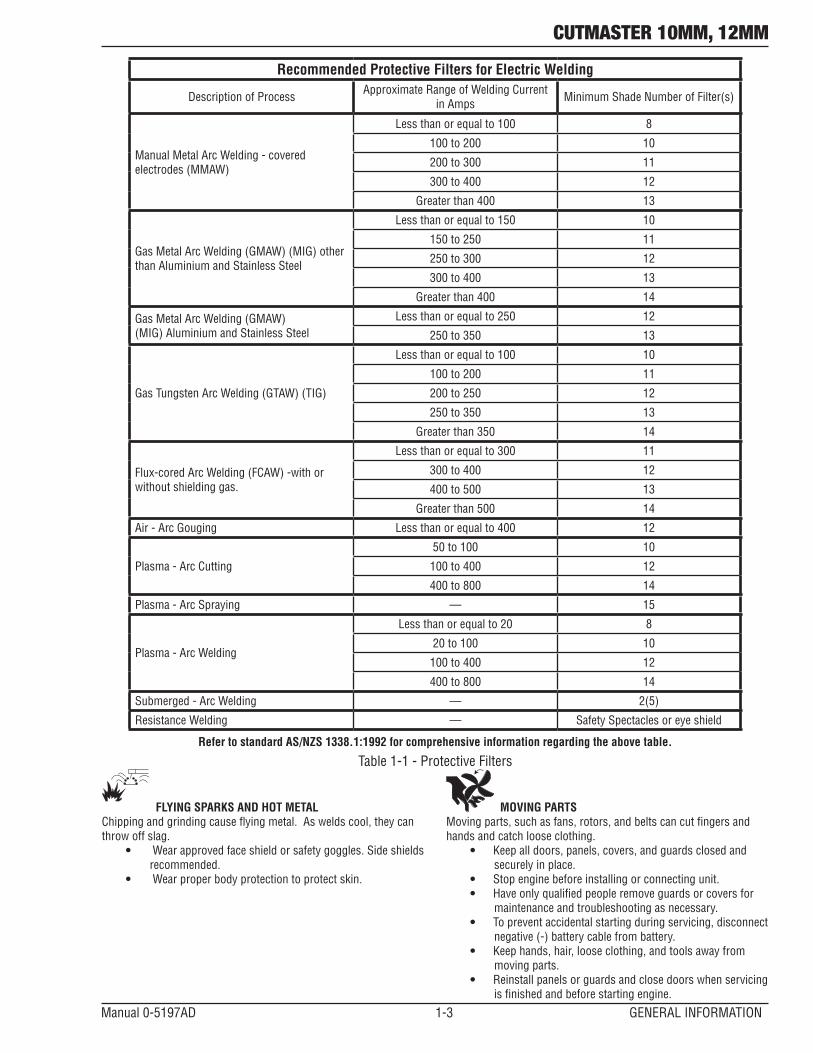
• Use the shade of lens as suggested in the following chart.
NOTE
These values apply where the actual arc is clearly seen. Experience has shown that lighter filters may be used when the arc is hidden by the workpiece.
CUTMASTER 10MM, 12MM
Manual 0-5197AD 1-3 GENERAL INFORMATION
Recommended Protective Filters for Electric Welding
Description of Process Approximate Range of Welding Current in Amps Minimum Shade Number of Filter(s)
Manual Metal Arc Welding - covered electrodes (MMAW)
Less than or equal to 100 8
100 to 200 10
200 to 300 11
300 to 400 12
Greater than 400 13
Gas Metal Arc Welding (GMAW) (MIG) other than Aluminium and Stainless Steel
Less than or equal to 150 10
150 to 250 11
250 to 300 12
300 to 400 13
Greater than 400 14
Gas Metal Arc Welding (GMAW)(MIG) Aluminium and Stainless Steel
Less than or equal to 250 12
250 to 350 13
Gas Tungsten Arc Welding (GTAW) (TIG)
Less than or equal to 100 10
100 to 200 11
200 to 250 12
250 to 350 13
Greater than 350 14
Flux-cored Arc Welding (FCAW) -with or without shielding gas.
Less than or equal to 300 11
300 to 400 12
400 to 500 13
Greater than 500 14
Air - Arc Gouging Less than or equal to 400 12
Plasma - Arc Cutting
50 to 100 10
100 to 400 12
400 to 800 14
Plasma - Arc Spraying — 15
Plasma - Arc Welding
Less than or equal to 20 8
20 to 100 10
100 to 400 12
400 to 800 14
Submerged - Arc Welding — 2(5)
Resistance Welding — Safety Spectacles or eye shield
Refer to standard AS/NZS 1338.1:1992 for comprehensive information regarding the above table.
Table 1-1 - Protective Filters
FLYING SPARKS AND HOT METALChippingandgrindingcauseflyingmetal.Asweldscool,theycanthrow off slag.
• Wear approved face shield or safety goggles. Side shields recommended.
• Wear proper body protection to protect skin.
MOVING PARTSMoving parts, such as fans, rotors, and belts can cut fingers and hands and catch loose clothing.
• Keepalldoors,panels,covers,andguardsclosedandsecurely in place.
• Stop engine before installing or connecting unit.• Have only qualified people remove guards or covers for
maintenance and troubleshooting as necessary.• To prevent accidental starting during servicing, disconnect
negative (-) battery cable from battery.• Keephands,hair,looseclothing,andtoolsawayfrom
moving parts.• Reinstall panels or guards and close doors when servicing
is finished and before starting engine.

CUTMASTER 10MM, 12MM
GENERAL INFORMATION 1-4 Manual 0-5197AD
CYLINDERS CAN EXPLODEShielding gas cylinders contain gas under high pressure. If dam-aged, a cylinder can explode. Since gas cylinders are normally part of the welding process, be sure to treat them carefully.• Protect compressed gas cylinders from excessive heat, mechani-
cal shocks, and arcs.• Install and secure cylinders in an upright position by chain-
ing them to a stationary support or equipment cylinder rack to prevent falling or tipping.
• Keepcylindersawayfromanyweldingorotherelectricalcircuits.• Never allow a welding electrode to touch any cylinder.• Use only correct shielding gas cylinders, regulators, hoses, and
fittings designed for the specific application; maintain them and associated parts in good condition.
• Turn face away from valve outlet when opening cylinder valve.• Keepprotectivecapinplaceovervalveexceptwhencylinderisin
use or connected for use.• Read and follow instructions on compressed gas cylinders,
associated equipment, and CGA publication P-1 listed in Safety Standards.
! WARNING
This product, when used for welding or cutting, produces fumes or gases which contain chemicals know to the State of California to cause birth defects and, in some cases, cancer. (California Health & Safety code Sec. 25249.5 et seq.)
NOTE
Considerations About Welding And The Effects of Low Frequency Electric and Magnetic Fields.
The following is a quotation from the General Conclusions Section of the U.S. Congress, Office of Technology Assessment, Biological Effects of Power Frequency Electric & Magnetic Fields - Background Paper, OTA-BP-E-63 (Washington, DC: U.S. Government Printing Office,May1989):“...thereisnowaverylargevolumeofscientificfindings based on experiments at the cellular level and from studies with animals and people which clearly establish that low frequency magnetic fields and interact with, and produce changes in, biological systems. While most of this work is of very high quality, the results are complex. Current scientific understanding does not yet allow us to interpret the evidence in a single coherent framework. Even more frustrating, it does not yet allow us to draw definite conclusions about questions of possible risk or to offer clear science-based advice on strategiestominimizeoravoidpotentialrisks.”Toreducemagneticfields in the workplace, use the following procedures.
1. Keepcablesclosetogetherbytwistingortapingthem.2. Arrange cables to one side and away from the operator.3. Do not coil or drape cable around the body.4. Keepweldingpowersourceandcablesasfarawayfrom
body as practical.
ABOUT PACEMAKERS:
The above procedures are among those also normally recommended for pacemaker wearers. Consult your doctor for complete information.
1.03 PublicationsRefer to the following standards or their latest revisions for more information:1. OSHA, SAFETY AND HEALTH STANDARDS, 29CFR 1910, obtain-
able from the Superintendent of Documents, U.S. Government Printing Office, Washington, D.C. 20402
2. ANSI Standard Z49.1, SAFETY IN WELDING AND CUTTING, ob-tainable from the American Welding Society, 550 N.W. LeJeune Rd, Miami, FL 33126
3. NIOSH, SAFETY AND HEALTH IN ARC WELDING AND GAS WELDING AND CUTTING, obtainable from the Superintendent of Documents, U.S. Government Printing Office, Washington, D.C. 20402
4. ANSI Standard Z87.1, SAFE PRACTICES FOR OCCUPATION AND EDUCATIONAL EYE AND FACE PROTECTION, obtainable from American National Standards Institute, 1430 Broadway, New York, NY 10018
5. ANSI Standard Z41.1, STANDARD FOR MEN’S SAFETY-TOE FOOTWEAR, obtainable from the American National Standards Institute, 1430 Broadway, New York, NY 10018
6. ANSI Standard Z49.2, FIRE PREVENTION IN THE USE OF CUTTING AND WELDING PROCESSES, obtainable from American National Standards Institute, 1430 Broadway, New York, NY 10018
7. AWS Standard A6.0, WELDING AND CUTTING CONTAINERS WHICH HAVE HELD COMBUSTIBLES, obtainable from American Welding Society, 550 N.W. LeJeune Rd, Miami, FL 33126
8. NFPA Standard 51, OXYGEN-FUEL GAS SYSTEMS FOR WELDING, CUTTING AND ALLIED PROCESSES, obtainable from the National Fire Protection Association, Batterymarch Park, Quincy, MA 02269
9. NFPA Standard 70, NATIONAL ELECTRICAL CODE, obtainable from the National Fire Protection Association, Batterymarch Park, Quincy, MA 02269
10. NFPA Standard 51B, CUTTING AND WELDING PROCESSES, obtainable from the National Fire Protection Association, Bat-terymarch Park, Quincy, MA 02269
11. CGA Pamphlet P-1, SAFE HANDLING OF COMPRESSED GASES IN CYLINDERS, obtainable from the Compressed Gas Association, 1235 Jefferson Davis Highway, Suite 501, Arlington, VA 22202
12. CSA Standard W117.2, CODE FOR SAFETY IN WELDING AND CUTTING, obtainable from the Canadian Standards Association, Standards Sales, 178 Rexdale Boulevard, Rexdale, Ontario, Canada M9W 1R3
13. NWSA booklet, WELDING SAFETY BIBLIOGRAPHY obtainable from the National Welding Supply Association, 1900 Arch Street, Philadelphia, PA 19103
14. American Welding Society Standard AWSF4.1, RECOMMENDED SAFE PRACTICES FOR THE PREPARATION FOR WELDING AND CUTTING OF CONTAINERS AND PIPING THAT HAVE HELD HAZ-ARDOUS SUBSTANCES, obtainable from the American Welding Society, 550 N.W. LeJeune Rd, Miami, FL 33126
15. ANSI Standard Z88.2, PRACTICE FOR RESPIRATORY PROTEC-TION, obtainable from American National Standards Institute, 1430 Broadway, New York, NY 10018

CUTMASTER 10MM, 12MM
Manual 0-5197AD 1-5 GENERAL INFORMATION
1.04 Declaration of ConformityManufacturer: Thermadyne CompanyAddress: 82 Benning Street West Lebanon, New Hampshire 03784 USA
The equipment described in this manual conforms to all applicable aspects and regulations of the ‘Low Voltage Directive’ (European Council Directive 73/23/EEC as amended by Council Directive 93/68/EEC) and to the National legislation for the enforcement of this Directive.
The equipment described in this manual conforms to all applicable aspects and regulations of the "EMC Directive" (European Council Directive 89/336/EEC) and to the National legislation for the enforcement of this Directive.
Serial numbers are unique with each individual piece of equipment and details description, parts used to manufacture a unit and date of manufacture.
National Standard and Technical Specifications
The product is designed and manufactured to a number of standards and technical requirements. Among them are:
• CSA(CanadianStandardsAssociation)standardC22.2number60forArcweldingequipment.
• UL(UnderwritersLaboratory)rating94VOflammabilitytestingforallprinted-circuitboardsused.
• CENELECEN50199EMCProductStandardforArcWeldingEquipment.
• ISO/IEC60974-1(BS638-PT10)(EN60974-1)(EN50192)(EN50078)applicabletoplasmacuttingequipmentandassociatedaccessories.
• IEC60974-10applicabletoIndustrialEquipment-genericemissionsandregulations
• AS1674Safetyinweldingandalliedprocesses.
• 2001/95/ECRoHSdirective.
• AS60974.1ArcWeldingEquipmentWeldingPowerSources.
For environments with increased hazard of electrical shock, Power Supplies bearing the mark conform to EN50192 when used in conjunction with hand torches with exposed cutting tips, if equipped with properly installed standoff guides.
• Extensive product design verification is conducted at themanufacturing facility as part of the routinedesign andmanufacturingprocess. This is to ensure the product is safe, when used according to instructions in this manual and related industry standards, and performs as specified. Rigorous testing is incorporated into the manufacturing process to ensure the manufactured product meets or exceeds all design specifications.
Thermadyne has been manufacturing products for more than 30 years, and will continue to achieve excellence in our area of manufacture.

CUTMASTER 10MM, 12MM
GENERAL INFORMATION 1-6 Manual 0-5197AD
This Page Intentionally Blank
CUTMASTER 10MM, 12MM
Manual 0-5197AD 2-1 SYSTEM INTRODUCTION
SECTION 2 SYSTEM: INTRODUCTION
2.01 How To Use This ManualThis Operating Manual applies to just specification or part numbers listed on page i. To ensure safe operation, read the entire manual, including the chapter on safety instructions and warnings. Throughout this manual, the words WARN-ING, CAUTION, and NOTE may appear. Pay particular atten-tion to the information provided under these headings. These special annotations are easily recognized as follows:
! WARNING
A WARNING gives information regarding possible personal injury.
CAUTION
A CAUTION refers to possible equipment damage.
NOTE
A NOTE offers helpful information concerning certain operating procedures.
Additional copies of this manual may be purchased by con-tacting Thermal Dynamics at the address and phone number in your area listed in the inside back cover of this manual. Include the Operating Manual number and equipment identi-fication numbers.Electronic copies of this manual can also be downloaded at no charge in Acrobat PDF format by going to the Thermal Dynamics web site listed below and clicking on Thermal Dynamics and then on the Literature link:http://www.thermal-dynamics.com
2.02 Equipment IdentificationThe unit’s identification number (specification or part num-ber), model, and serial number usually appear on a data tag attached to the rear panel. Equipment which does not have a data tag such as torch and cable assemblies are identified only by the specification or part number printed on loosely attached card or the shipping container. Record these num-bers on the bottom of page (i) for future reference.
2.03 Receipt Of EquipmentWhen you receive the equipment, check it against the invoice to make sure it is complete and inspect the equipment for possible damage due to shipping. If there is any damage, no-tify the carrier immediately to file a claim. Furnish complete information concerning damage claims or shipping errors to the location in your area listed in the inside back cover of this manual.Include all equipment identification numbers as described above along with a full description of the parts in error.Move the equipment to the installation site before unpacking the unit. Use care to avoid damaging the equipment when using bars, hammers, etc., to unpack the unit.
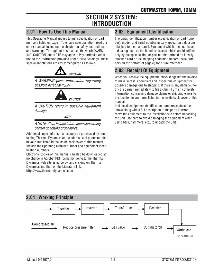
2.04 Working Principle
Rectifier Inverter Transformer Rectifier
Reduce pressure, filter Gas valve Cutting torch Workpiece
Compressed air
Art # A-09204_AB
CUTMASTER 10MM, 12MM
SYSTEM INTRODUCTION 2-2 Manual 0-5197AD
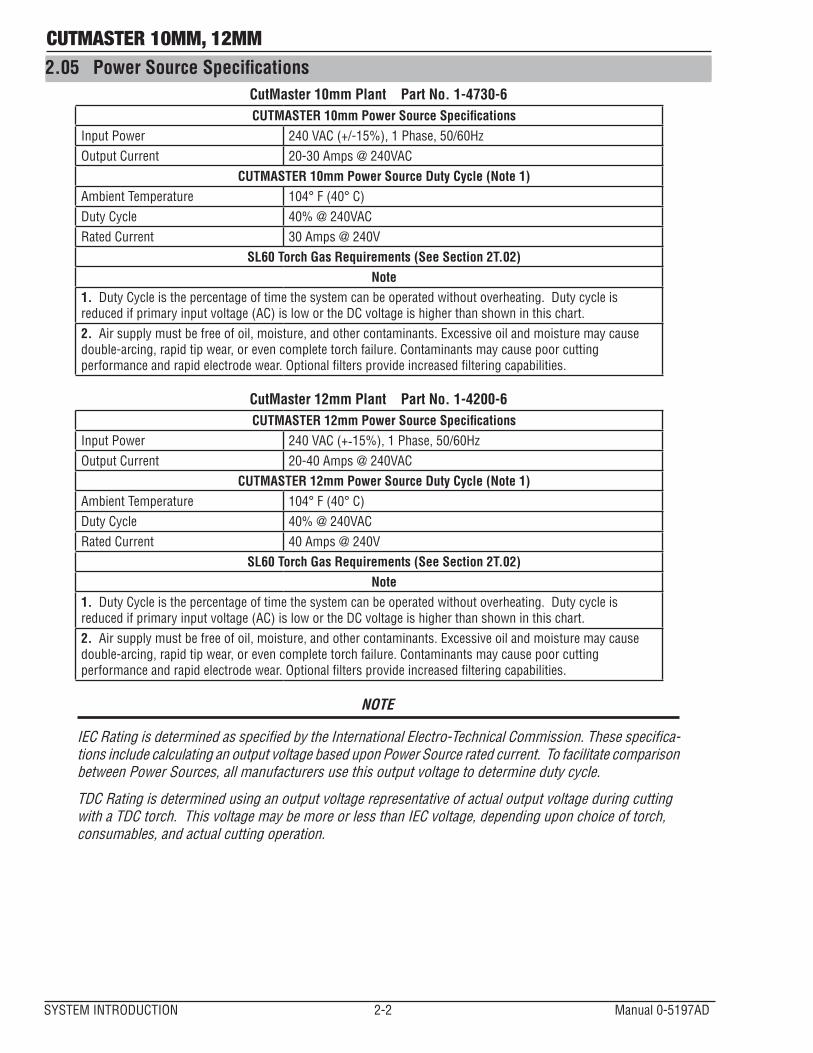
2.05 Power Source SpecificationsCutMaster 10mm Plant Part No. 1-4730-6CUTMASTER 10mm Power Source Specifications
Input Power 240 VAC (+/-15%), 1 Phase, 50/60HzOutput Current 20-30 Amps @ 240VAC
CUTMASTER 10mm Power Source Duty Cycle (Note 1)Ambient Temperature 104° F (40° C)Duty Cycle 40% @ 240VACRated Current 30 Amps @ 240V
SL60 Torch Gas Requirements (See Section 2T.02)Note
1. Duty Cycle is the percentage of time the system can be operated without overheating. Duty cycle is reduced if primary input voltage (AC) is low or the DC voltage is higher than shown in this chart.2. Air supply must be free of oil, moisture, and other contaminants. Excessive oil and moisture may cause double-arcing, rapid tip wear, or even complete torch failure. Contaminants may cause poor cutting performance and rapid electrode wear. Optional filters provide increased filtering capabilities.
CutMaster 12mm Plant Part No. 1-4200-6CUTMASTER 12mm Power Source Specifications
Input Power 240 VAC (+-15%), 1 Phase, 50/60Hz Output Current 20-40 Amps @ 240VAC
CUTMASTER 12mm Power Source Duty Cycle (Note 1)Ambient Temperature 104° F (40° C)Duty Cycle 40% @ 240VACRated Current 40 Amps @ 240V
SL60 Torch Gas Requirements (See Section 2T.02)Note
1. Duty Cycle is the percentage of time the system can be operated without overheating. Duty cycle is reduced if primary input voltage (AC) is low or the DC voltage is higher than shown in this chart.2. Air supply must be free of oil, moisture, and other contaminants. Excessive oil and moisture may cause double-arcing, rapid tip wear, or even complete torch failure. Contaminants may cause poor cutting performance and rapid electrode wear. Optional filters provide increased filtering capabilities.
NOTE
IEC Rating is determined as specified by the International Electro-Technical Commission. These specifica-tions include calculating an output voltage based upon Power Source rated current. To facilitate comparison between Power Sources, all manufacturers use this output voltage to determine duty cycle.
TDC Rating is determined using an output voltage representative of actual output voltage during cutting with a TDC torch. This voltage may be more or less than IEC voltage, depending upon choice of torch, consumables, and actual cutting operation.

CUTMASTER 10MM, 12MM
Manual 0-5197AD 2-3 SYSTEM INTRODUCTION
26lb / 11.8kg7" (177mm)
18.5" (469.9mm)
9" (228.6mm)
CUTMASTER ®
A4020
30
Art # A-10216
Figure 2-1 - Power Source Dimensions & Weight
NOTE
Weight includes torch & leads, input power cord, and work cable with clamp.
CAUTION
ProvideclearanceforproperairflowthroughthePowerSource.Operationwithoutproperairflowwillinhibit proper cooling and reduce duty cycle.
CUTMASTER 10MM, 12MM
SYSTEM INTRODUCTION 2-4 Manual 0-5197AD
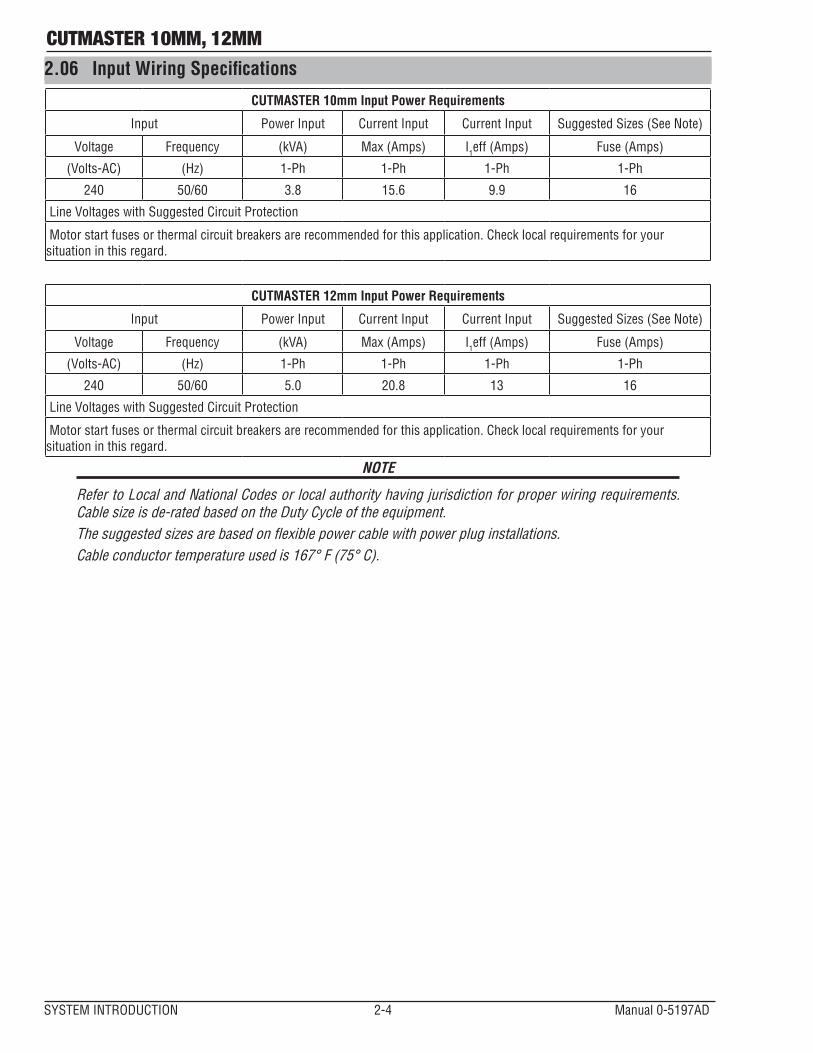
2.06 Input Wiring Specifications
CUTMASTER 10mm Input Power Requirements
Input Power Input Current Input Current Input Suggested Sizes (See Note)
Voltage Frequency (kVA) Max (Amps) I1eff (Amps) Fuse (Amps)
(Volts-AC) (Hz) 1-Ph 1-Ph 1-Ph 1-Ph
240 50/60 3.8 15.6 9.9 16
Line Voltages with Suggested Circuit Protection
Motor start fuses or thermal circuit breakers are recommended for this application. Check local requirements for your situation in this regard.
CUTMASTER 12mm Input Power Requirements
Input Power Input Current Input Current Input Suggested Sizes (See Note)
Voltage Frequency (kVA) Max (Amps) I1eff (Amps) Fuse (Amps)
(Volts-AC) (Hz) 1-Ph 1-Ph 1-Ph 1-Ph
240 50/60 5.0 20.8 13 16
Line Voltages with Suggested Circuit Protection
Motor start fuses or thermal circuit breakers are recommended for this application. Check local requirements for your situation in this regard.
NOTE
Refer to Local and National Codes or local authority having jurisdiction for proper wiring requirements. Cable size is de-rated based on the Duty Cycle of the equipment.Thesuggestedsizesarebasedonflexiblepowercablewithpowerpluginstallations.Cable conductor temperature used is 167° F (75° C).
CUTMASTER 10MM, 12MM
Manual 0-5197AD 2-5 SYSTEM INTRODUCTION
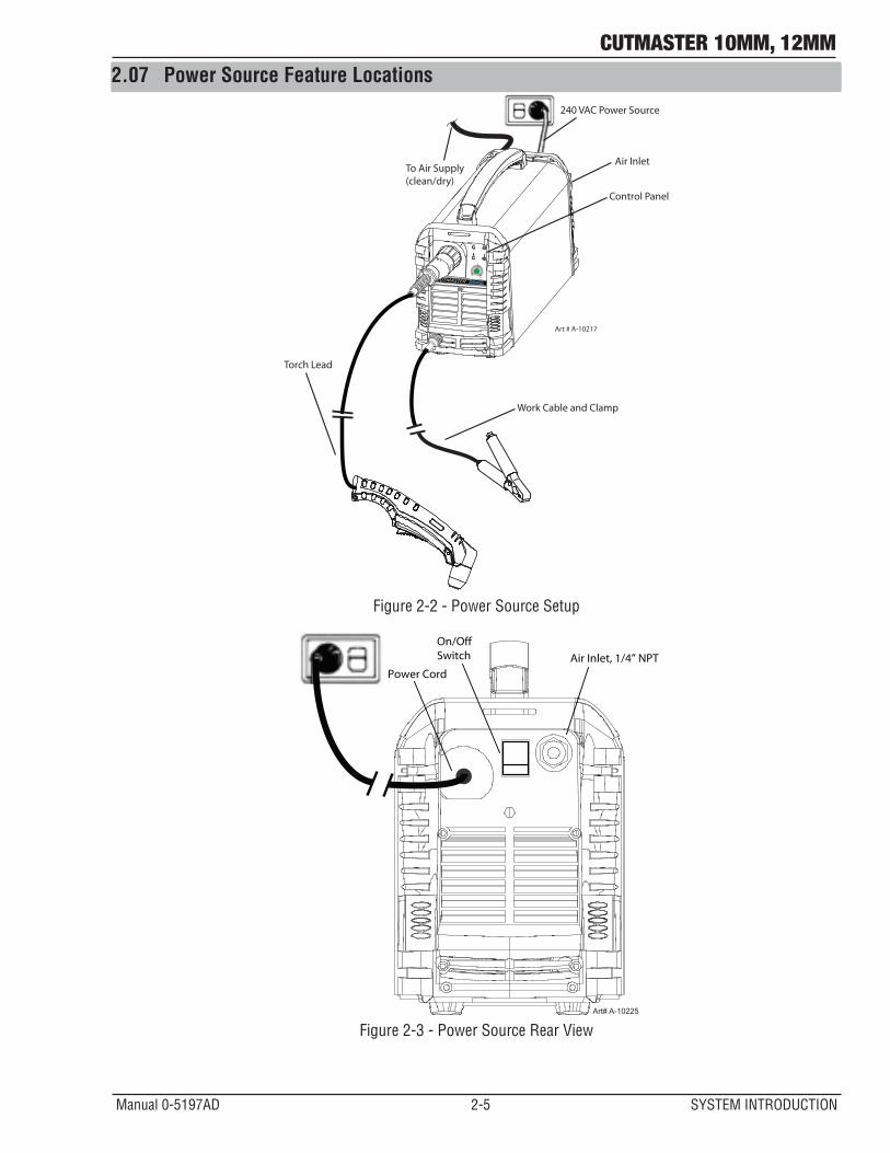
2.07 Power Source Feature Locations
Air Inlet
Control Panel
Torch Lead
240 VAC Power Source
Work Cable and Clamp
CUTMASTER ®
4020
30
Art # A-10217
To Air Supply (clean/dry)
Figure 2-2 - Power Source Setup
Art# A-10225
Air Inlet, 1/4” NPTOn/OffSwitch
Power Cord
Figure 2-3 - Power Source Rear View

CUTMASTER 10MM, 12MM
SYSTEM INTRODUCTION 2-6 Manual 0-5197AD
This Page Intentionally Blank
CUTMASTER 10MM, 12MM
Manual 0-5197AD 2T-1 TORCH INTRODUCTION
2T.01 Scope of Operating ManualThis manual contains descriptions, operating instructions and maintenance procedures for the SL60 Plasma Cutting Torch. Service of this equipment is restricted to properly trained personnel; unqualified personnel are strictly cautioned against attempting repairs or adjustments not covered in this manual, at the risk of voiding the Warranty. Read this manual thoroughly. A complete understanding of the characteristics and capabilities of this equipment will assure the dependable operation for which it was designed.
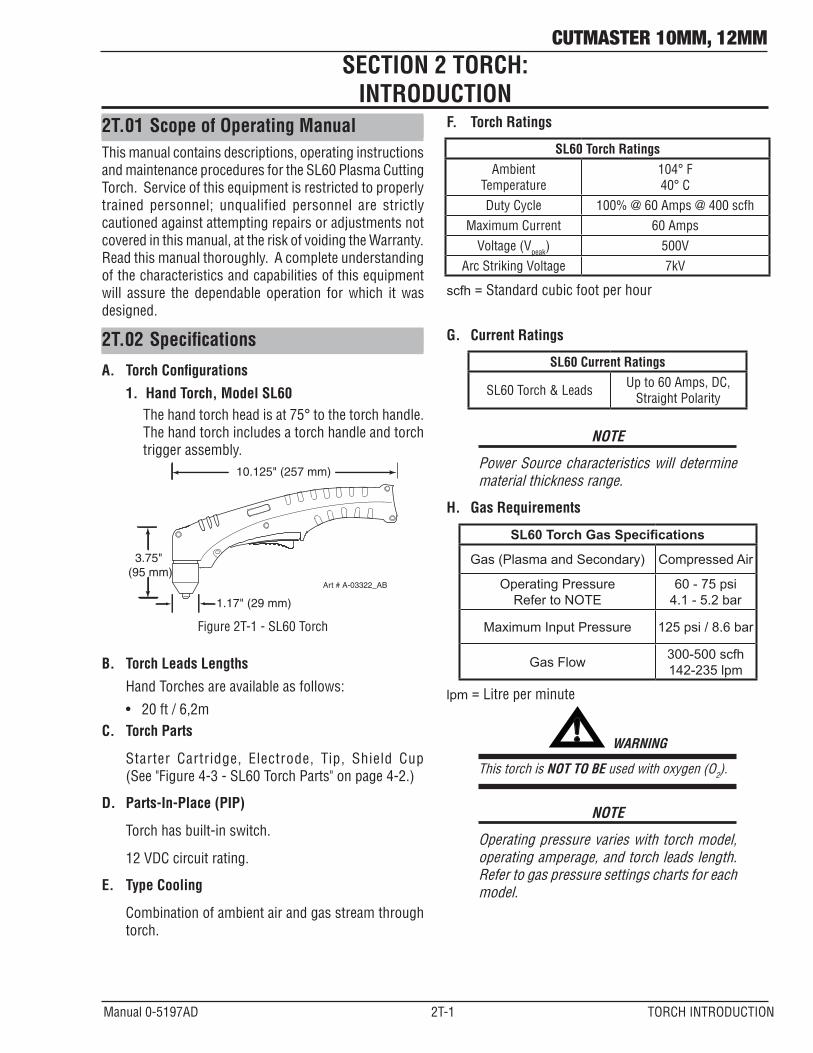
2T.02 Specifications
A. Torch Configurations
1. Hand Torch, Model SL60The hand torch head is at 75° to the torch handle. The hand torch includes a torch handle and torch trigger assembly.
10.125" (257 mm)
3.75" (95 mm)
1.17" (29 mm)
Art # A-03322_AB
Figure 2T-1 - SL60 Torch
B. Torch Leads Lengths
Hand Torches are available as follows:
• 20ft/6,2mC. Torch Parts
Starter Cartridge, Electrode, Tip, Shield Cup (See "Figure 4-3 - SL60 Torch Parts" on page 4-2.)
D. Parts-In-Place (PIP)
Torch has built-in switch.
12 VDC circuit rating.
E. Type Cooling
Combination of ambient air and gas stream through torch.
F. Torch Ratings
SL60 Torch RatingsAmbient
Temperature104° F 40° C
Duty Cycle 100% @ 60 Amps @ 400 scfhMaximum Current 60 Amps
Voltage (Vpeak) 500VArc Striking Voltage 7kV
scfh = Standard cubic foot per hour
G. Current Ratings
SL60 Current Ratings
SL60 Torch & Leads Up to 60 Amps, DC, Straight Polarity
NOTE
Power Source characteristics will determine material thickness range.
H. Gas Requirements
SL60 Torch Gas Specifications
Gas (Plasma and Secondary) Compressed Air
Operating PressureRefer to NOTE
60 - 75 psi4.1 - 5.2 bar
Maximum Input Pressure 125 psi / 8.6 bar
Gas Flow 300-500 scfh 142-235 lpm
lpm = Litre per minute
! WARNING
This torch is NOT TO BE used with oxygen (O2).
NOTE
Operating pressure varies with torch model, operating amperage, and torch leads length. Refer to gas pressure settings charts for each model.
SECTION 2 TORCH: INTRODUCTION
CUTMASTER 10MM, 12MM
TORCH INTRODUCTION 2T-2 Manual 0-5197AD
2T.03 Introduction to Plasma
A. Plasma Gas Flow
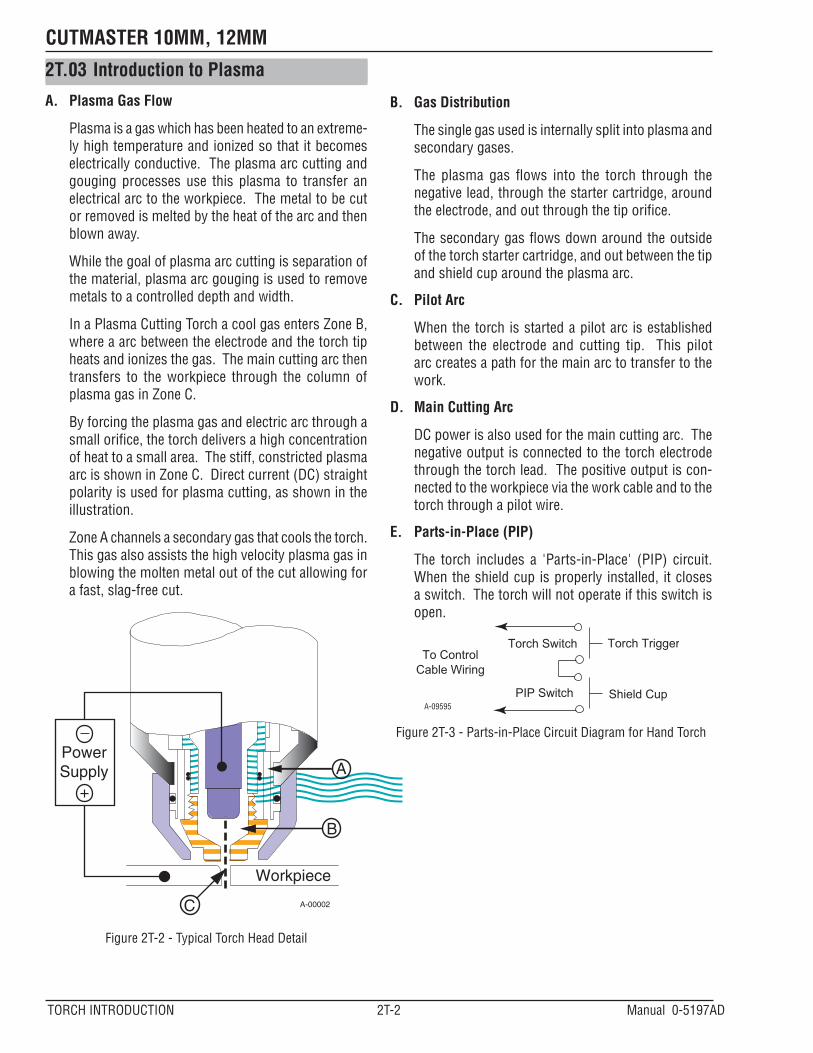
Plasma is a gas which has been heated to an extreme-ly high temperature and ionized so that it becomes electrically conductive. The plasma arc cutting and gouging processes use this plasma to transfer an electrical arc to the workpiece. The metal to be cut or removed is melted by the heat of the arc and then blown away.
While the goal of plasma arc cutting is separation of the material, plasma arc gouging is used to remove metals to a controlled depth and width.
In a Plasma Cutting Torch a cool gas enters Zone B, where a arc between the electrode and the torch tip heats and ionizes the gas. The main cutting arc then transfers to the workpiece through the column of plasma gas in Zone C.
By forcing the plasma gas and electric arc through a small orifice, the torch delivers a high concentration of heat to a small area. The stiff, constricted plasma arc is shown in Zone C. Direct current (DC) straight polarity is used for plasma cutting, as shown in the illustration.
Zone A channels a secondary gas that cools the torch. This gas also assists the high velocity plasma gas in blowing the molten metal out of the cut allowing for a fast, slag-free cut.
A-00002
Workpiece
PowerSupply
+
_
C
B
A
Figure 2T-2 - Typical Torch Head Detail
B. Gas Distribution
The single gas used is internally split into plasma and secondary gases.
The plasma gas flows into the torch through thenegative lead, through the starter cartridge, around the electrode, and out through the tip orifice.
Thesecondarygasflowsdownaroundtheoutsideof the torch starter cartridge, and out between the tip and shield cup around the plasma arc.
C. Pilot Arc
When the torch is started a pilot arc is established between the electrode and cutting tip. This pilot arc creates a path for the main arc to transfer to the work.
D. Main Cutting Arc
DC power is also used for the main cutting arc. The negative output is connected to the torch electrode through the torch lead. The positive output is con-nected to the workpiece via the work cable and to the torch through a pilot wire.
E. Parts-in-Place (PIP)
The torch includes a 'Parts-in-Place' (PIP) circuit. When the shield cup is properly installed, it closes a switch. The torch will not operate if this switch is open.
Torch Trigger
PIP Switch Shield Cup
To ControlCable Wiring
Torch Switch
A-09595
Figure 2T-3 - Parts-in-Place Circuit Diagram for Hand Torch

CUTMASTER 10MM, 12MM
Manual 0-5197AD 3-1 INSTALLATION
SECTION 3: INSTALLATION
3.01 Unpacking1. Use the packing lists to identify and account for each item.
A. Contents List for CutMaster 10mm Plant Part No. 1-4730-6
Description Quantity
CM 10mm Power Source 1 Work cable and clamp 5m (installed) 1 Carry bag 1 SL60 Torch 1 (Including SL60 Torch 20 ft/6.2m w/ATC, consumables set, spare parts kit) Shoulder Strap 1 Operating Manual 1
B. Contents List for CutMaster 12mm Plant Part No. 1-4200-6
Description Quantity
CM 12mm Power Source 1 Work cable and clamp 5m (installed) 1 Carry bag 1 SL60 Torch 1 (Including SL60 Torch 20 ft/6.2m w/ATC, consumables set, spare parts kit) Shoulder Strap 1 Operating Manual 1
2. Inspect each item for possible shipping damage. If damage is evident, contact your distributor and / or shipping company before proceeding with the installation.
3. Record Power Source and Torch model and serial numbers, purchase date and vendor name, in the information block at the front of this manual.
3.02 Lifting Options
The Power Source includes a handle for hand lifting only. Be sure unit is lifted and transported safely and securely.
WARNING
DO NOT touch live electrical parts.
Disconnect input power cord before moving unit.
! WARNING
FALLING EQUIPMENT can cause serious personal injury and can damage equipment.
HANDLE is not for mechanical lifting.• Only persons of adequate physical strength should lift the unit.
• Liftunitbythehandle,usingtwohands.Do not use straps for lifting.
• Useoptionalcartorsimilardeviceofadequate capacity to move unit.
• Placeunitonaproperskidandsecureinplace before transporting with a fork lift or other vehicle.

CUTMASTER 10MM, 12MM
INSTALLATION 3-2 Manual 0-5197AD
3.03 Air Supply Connections
A. Connecting Air Supply to Unit
The connection is the same for compressed air or indus-trial compressed air in gas cylinders.
1. Connect the gas line to the compressed air inlet port at the appropriate pressure.
Art # A-10223
Air Inlet, 1/4” NPT
On/OffSwitch
Figure 3-1 - Gas Connection to Compressed Air Input
1/4 NPT Hose Fitting
Hose Clamp
Gas Supply Hose
Filter Hose
Single-StageFilter Kit
No. 7-7507
ART# A-10675
Figure 3-2 - Optional Single - Stage Filter Installation for Compressed Air Input
B. Using Industrial Compressed Air In Gas Cylinders
When using industrial compressed air in gas cylinders as the gas supply:
1. Refer to the manufacturer’s specifications for installation and maintenance procedures for high pressure gas regulators.
2. Examine the cylinder valves to be sure they are clean and free of oil, grease or any foreign mate-rial.Brieflyopeneachcylindervalvetoblowoutany dust which may be present.
3. The cylinder must be equipped with an adjust-able high-pressure regulator capable of outlet pressures up to 100 psi (6.9 bar) maximum and flowsofatleast250scfh[Standardcubicfootperhour](120lpm)[literperminute].
4. Connect gas supply hose to the cylinder.
NOTE
Pressure should be set at 100 psi (6.9 bar) at the high pressure gas cylinder regulator.
Supply hose must be at least 1/4 inch (6mm) internal diameter.
For a secure seal, apply thread sealant to the fitting threads, according to manufacturer's instructions. DO NOT use Teflon tape as athread sealer, as small particles of the tape may break off and block the small gas pas-sages in the torch.

CUTMASTER 10MM, 12MM
Manual 0-5197AD 4-1 OPERATION
SECTION 4 SYSTEM: OPERATION
4.01 Control Panel
A
30
20 40
Art # A-10218
CUTMASTER®
AC Indicator
Overheat Indicator
Air Indicator
DC Indicator (Ready)
Air Inlet,1/4” NPT
On/O�Switch
Power Cord
12mm
1. ON/OFF Switch (Power Switch/Lamp)Controls input power to the Power Source. I is ON (Red Lamp), O is OFF.
2. (A) Output Current Control
Sets the desired output current. If the overload protection (fuse or circuit breaker) on the input power circuit opens frequently, either reduce cutting output, reduce the cutting time, or connect the unit to more adequate input power. For 240V input power, the maximum output is 40 Amps. Refer to Section "2.05 Power Source Specifications" on page 2-2. for input power requirements.
3. AC Indicator
Steady light indicates Power Source is ready for operation.
4. OVERHEAT Indicator (TEMP Indicator)
Indicator is normally OFF. Indicator is ON when internal temperature exceeds normal limits. Allow the unit to run with the fan ON until the temp indicator turns OFF.
5. AIR Indicator
AIR indicator light should be ON when there is sufficient gas pressure.
6. READY (DC Indicator)
Indicator is ON when DC output circuit is active.
Figure 4-1 - Front Control Panel Figure 4-2 - Rear Controls
CUTMASTER 10MM, 12MM
OPERATION 4-2 Manual 0-5197AD
4.02 Preparations for OperatingAt the start of each operating session:
WARNING
Disconnect primary power at the source before assembling or disassembling Power Source, torch parts, or torch and leads assemblies.
NOTE
All consumables must be correctly installed and maintained to ensure correct operation.
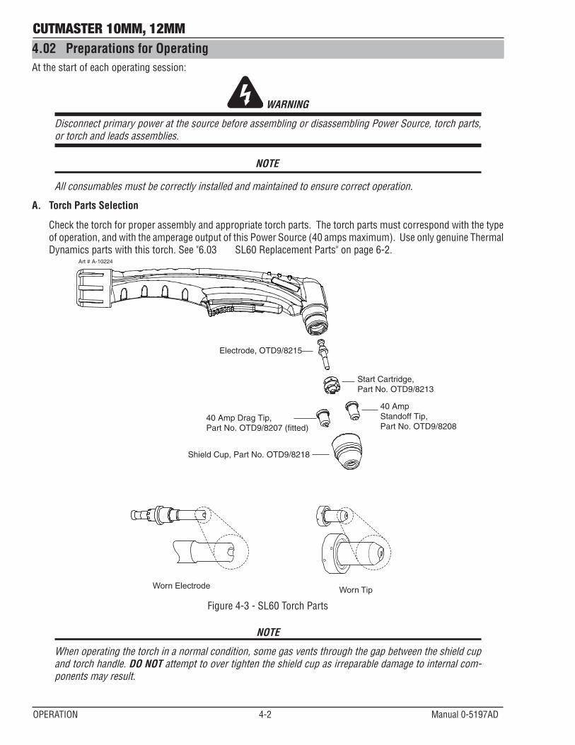
A. Torch Parts Selection
Check the torch for proper assembly and appropriate torch parts. The torch parts must correspond with the type of operation, and with the amperage output of this Power Source (40 amps maximum). Use only genuine Thermal Dynamics parts with this torch. See "6.03 SL60 Replacement Parts" on page 6-2.
Art # A-10224
Start Cartridge, Part No. OTD9/8213
Electrode, OTD9/8215
Worn Electrode Worn Tip
40 Amp Drag Tip, Part No. OTD9/8207 (fitted)
Shield Cup, Part No. OTD9/8218
40 Amp Standoff Tip, Part No. OTD9/8208
Figure 4-3 - SL60 Torch Parts
NOTE
When operating the torch in a normal condition, some gas vents through the gap between the shield cup and torch handle. DO NOT attempt to over tighten the shield cup as irreparable damage to internal com-ponents may result.

CUTMASTER 10MM, 12MM
Manual 0-5197AD 4-3 OPERATION
B. Torch Connection
Check that the torch is properly connected.
C. Check Primary Input Power Source
1. Check the power source for proper input voltage. Make sure the input power source meets the power require-ments for the unit per Section "2.05 Power Source Specifications" on page 2-2.
2. Connect the input power cable (or CLOSE the main disconnect switch) to supply power to the system.D. Gas Selection
Ensure gas source meets requirements listed in Section "H. Gas Requirements" on page 2T-1. Check connec-tions and turn gas supply ON.
E. Connect Work Cable
Clamp the work cable to the workpiece or cutting table. The area must be free from oil, paint and rust. Connect only to the main part of the workpiece; do not connect to the part to be cut off.
Art # A-03387
Figure 4-4 - Work Cable ConnectionF. Power ON
Place the Power Source ON/OFF switch to the ON (I) position. Power indicator turns ON.
Art# A-10225
Air Inlet, 1/4” NPTOn/OffSwitch
Power Cord
Figure 4-5 - Rear Panel with ON/OFF Switch
A
30
20 40Art# A-10219
Power indicator
Figure 4-6 - Front Panel with Power ON/OFF Indicator

CUTMASTER 10MM, 12MM
OPERATION 4-4 Manual 0-5197AD
4.03 Sequence of OperationThe following is a typical sequence of operation for this Power Source.
1. Place the ON/OFF switch on the Power Source to ON (up) position (Red indicator lamp is illuminated).a. AC indicator turns ON; fan turns ON.
NOTE
During initial power up, there will be a delay of about 2 seconds before the AC Indicator light will illuminate andthepre-flowgasandfanstarts.Thegaswillautomaticallyflowfromtorchforapproximately10seconds(only after the AC Indicator lamp is illuminated) (The AC Indicator lamp and fan turns ON approximately 2 seconds after the ON/OFF switch is enabled), this is a process that makes sure all inputs (gas, input power, torch connection, and torch parts) are acknowledged for proper operation.
2. Wear protective clothing, including welding gloves and appropriate eye protection (See "Table 1-1 - Protective Filters" on page 1-3). Place tip on workpiece and pull trigger. Arc will initiate and start cutting material.
•Standoff Cutting With Hand TorchNOTE
For best performance and parts life, always use the correct parts for the type of operation.
A. The torch can be comfortably held in one hand or steadied with two hands. Position the hand to press the Trigger on the torch handle. With the hand torch, the hand may be positioned close to the torch head for maximum control or near the back end for maximum heat protec-tion. Choose the holding technique that feels most comfortable and allows good control and movement.
NOTE
The tip should never come in contact with the workpiece except during drag cutting operations.
B. Depending on the cutting operation, do one of the following: a). For drag cutting, place the tip on the plate
holding the torch at a angle to the plate so that only one edge of the tip is in contact with the plate. This prevents damage to the tip during the piercing process.
b). For standoff cutting, hold the torch tip on the workpiece, pull the trigger. After the arc is initiated lift the tip to 1/8" - 3/8" (3-4mm) off the work.
Art # A-09342
Trigger
Trigger Release
Figure 4-7 - Torch Trigger Release
A-00024_AB
Shield Cup
Torch
Standoff Distance1/8" - 3/8" (3 - 9mm)
Figure 4-8 - Standoff Distance
3
4
Trigger
21
Trigger Release
Art# A-09341
Figure 4-9 - Standoff Cutting
CUTMASTER 10MM, 12MM
Manual 0-5197AD 4-5 OPERATION
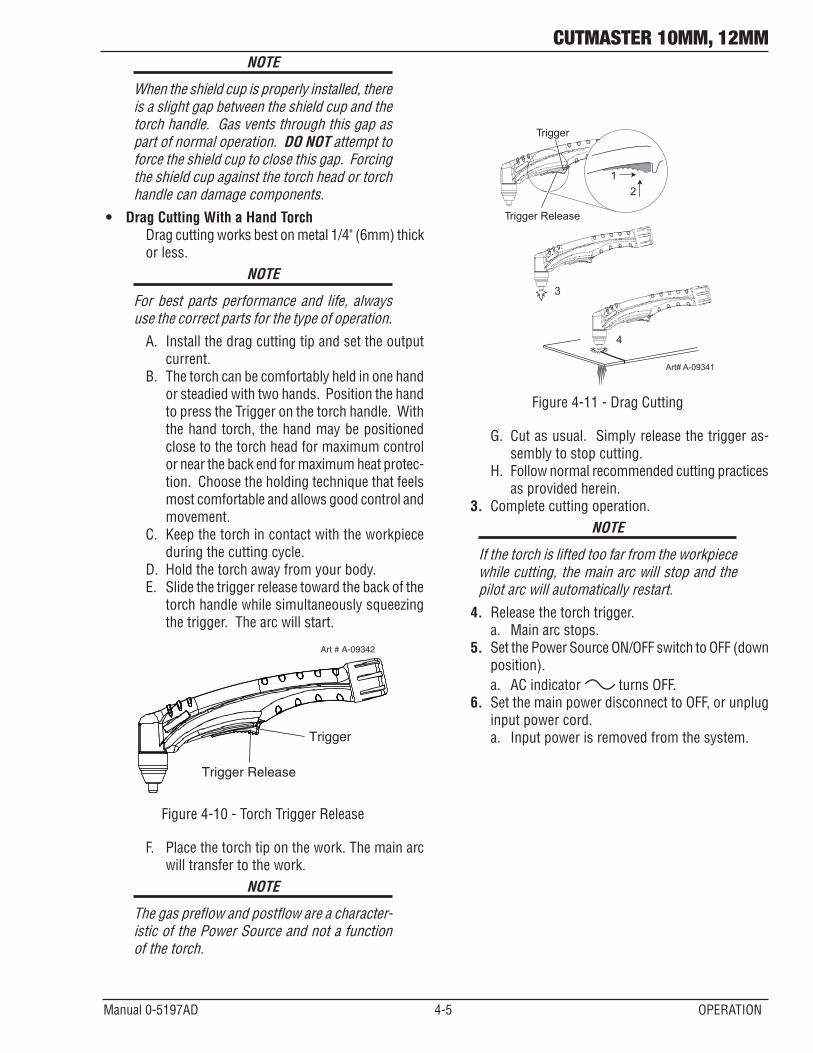
NOTE
When the shield cup is properly installed, there is a slight gap between the shield cup and the torch handle. Gas vents through this gap as part of normal operation. DO NOT attempt to force the shield cup to close this gap. Forcing the shield cup against the torch head or torch handle can damage components.
• Drag Cutting With a Hand Torch Drag cutting works best on metal 1/4" (6mm) thick
or less.NOTE
For best parts performance and life, always use the correct parts for the type of operation.
A. Install the drag cutting tip and set the output current.
B. The torch can be comfortably held in one hand or steadied with two hands. Position the hand to press the Trigger on the torch handle. With the hand torch, the hand may be positioned close to the torch head for maximum control or near the back end for maximum heat protec-tion. Choose the holding technique that feels most comfortable and allows good control and movement.
C. Keepthetorchincontactwiththeworkpieceduring the cutting cycle.
D. Hold the torch away from your body.E. Slide the trigger release toward the back of the
torch handle while simultaneously squeezing the trigger. The arc will start.
Art # A-09342
Trigger
Trigger Release
Figure 4-10 - Torch Trigger Release
F. Place the torch tip on the work. The main arc will transfer to the work.
NOTE
Thegaspreflowandpostflowareacharacter-istic of the Power Source and not a function of the torch.
3
4
Trigger
21
Trigger Release
Art# A-09341
Figure 4-11 - Drag Cutting
G. Cut as usual. Simply release the trigger as-sembly to stop cutting.
H. Follow normal recommended cutting practices as provided herein.
3. Complete cutting operation.NOTE
If the torch is lifted too far from the workpiece while cutting, the main arc will stop and the pilot arc will automatically restart.
4. Release the torch trigger. a. Main arc stops.
5. Set the Power Source ON/OFF switch to OFF (down position).a. AC indicator turns OFF.
6. Set the main power disconnect to OFF, or unplug input power cord.a. Input power is removed from the system.
CUTMASTER 10MM, 12MM
OPERATION 4-6 Manual 0-5197AD
4.04 Cut Quality
NOTE
Cut quality depends heavily on setup and parameters such as torch standoff, alignment with the workpiece, cutting speed, gas pres-sures, and operator ability.
Refer to Appendix pages for additional infor-mation as related to the Power Source used.
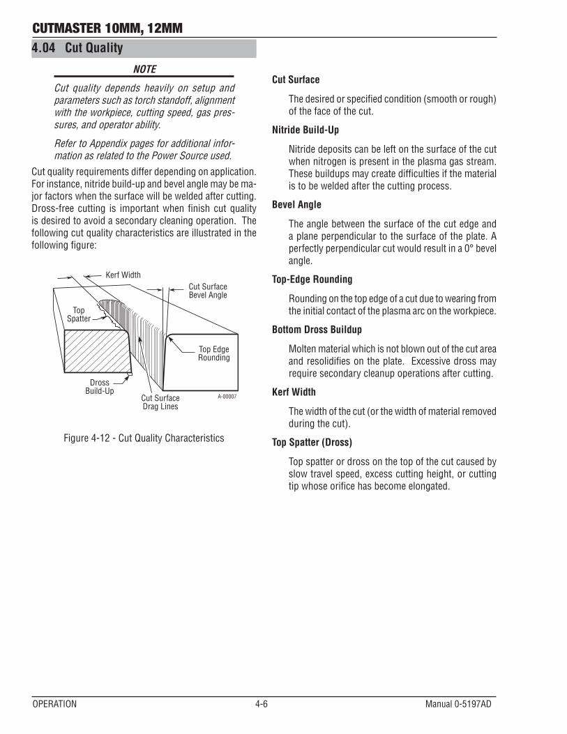
Cut quality requirements differ depending on application. For instance, nitride build-up and bevel angle may be ma-jor factors when the surface will be welded after cutting. Dross-free cutting is important when finish cut quality is desired to avoid a secondary cleaning operation. The following cut quality characteristics are illustrated in the following figure:
Kerf WidthCut SurfaceBevel Angle
Top EdgeRounding
Cut SurfaceDrag Lines
DrossBuild-Up
TopSpatter
A-00007
Figure 4-12 - Cut Quality Characteristics
Cut Surface
The desired or specified condition (smooth or rough) of the face of the cut.
Nitride Build-Up
Nitride deposits can be left on the surface of the cut when nitrogen is present in the plasma gas stream. These buildups may create difficulties if the material is to be welded after the cutting process.
Bevel Angle
The angle between the surface of the cut edge and a plane perpendicular to the surface of the plate. A perfectly perpendicular cut would result in a 0° bevel angle.
Top-Edge Rounding
Rounding on the top edge of a cut due to wearing from the initial contact of the plasma arc on the workpiece.
Bottom Dross Buildup
Molten material which is not blown out of the cut area and resolidifies on the plate. Excessive dross may require secondary cleanup operations after cutting.
Kerf Width
The width of the cut (or the width of material removed during the cut).
Top Spatter (Dross)
Top spatter or dross on the top of the cut caused by slow travel speed, excess cutting height, or cutting tip whose orifice has become elongated.
CUTMASTER 10MM, 12MM
Manual 0-5197AD 4-7 OPERATION
4.05 General Cutting Information
WARNING
Disconnect primary power at the source before disassembling the power source, torch, or torch leads.
Frequently review the Important Safety Pre-cautions at the front of this manual. Be sure the operator is equipped with proper gloves, clothing, eye and ear protection. Make sure no part of the operator’s body comes into contact with the workpiece while the torch is activated.\
CAUTION
Sparks from the cutting process can cause damage to coated, painted, and other surfaces such as glass, plastic and metal.
NOTE
Handle torch leads with care and protect them from damage.
Torch Standoff
Improper standoff (the distance between the torch tip and workpiece) can adversely affect tip life as well as shield cup life. Standoff may also significantly affect the bevel angle. Reducing standoff will generally result in a more square cut.
Edge Starting
For edge starts, hold the torch perpendicular to the workpiece with the front of the tip near (not touching) the edge of the workpiece at the point where the cut is to start. When starting at the edge of the plate, do not pause at the edge and force the arc to "reach" for the edge of the metal. Establish the cutting arc as quickly as possible.
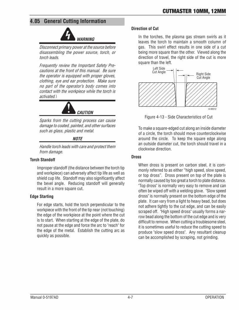
Direction of Cut
In the torches, the plasma gas stream swirls as it leaves the torch to maintain a smooth column of gas. This swirl effect results in one side of a cut being more square than the other. Viewed along the direction of travel, the right side of the cut is more square than the left.
Right SideCut Angle
Left SideCut Angle
A-00512
Figure 4-13 - Side Characteristics of Cut
To make a square-edged cut along an inside diameter of a circle, the torch should move counterclockwise around the circle. To keep the square edge along an outside diameter cut, the torch should travel in a clockwise direction.
Dross
When dross is present on carbon steel, it is com-monlyreferredtoaseither“highspeed,slowspeed,ortopdross”.Drosspresentontopoftheplateisnormally caused by too great a torch to plate distance. "Top dross" is normally very easy to remove and can often be wiped off with a welding glove. "Slow speed dross" is normally present on the bottom edge of the plate. It can vary from a light to heavy bead, but does not adhere tightly to the cut edge, and can be easily scraped off. "High speed dross" usually forms a nar-row bead along the bottom of the cut edge and is very difficult to remove. When cutting a troublesome steel, it is sometimes useful to reduce the cutting speed to produce "slow speed dross". Any resultant cleanup can be accomplished by scraping, not grinding.

CUTMASTER 10MM, 12MM
OPERATION 4-8 Manual 0-5197AD
This Page Intentionally Blank

CUTMASTER 10MM, 12MM
Manual 0-5197AD 5-1 SYSTEM SERVICE
SECTION 5 SYSTEM: SERVICE
5.01 General MaintenanceWarning! There are extremely dangerous voltage and power levels present inside this product. Do not attempt to open or repair unless you are a qualifiedelectrical tradesperson and you have had training in power measurementsand troubleshooting techniques. If major complex subassemblies are faulty,then the Cutting Power Source must be returned to an Accredited ThermalDynamics Service Provider for repair.
Each Use
Visual check oftorch tip and electrode
Weekly
Visually inspect the torch body tip, electrode, start cartridge and shield cup
Visually inspect thecables and leads.Replace as needed
3 Months
6 Months
Replace all broken parts
Visually check and Carefully clean the interior
Maintain more oftenif used under severeconditions
Art # A-09343_AC
Cleanexteriorof power supply
CUTMASTER ®42CURRENT
A20 40
30
CUTMASTER ®42CURRENT
A20 40
30
CUTMASTER 10MM, 12MM
SERVICE SYSTEM 5-2 Manual 0-5197AD
A. Every three months
Check external air filter, replace if necessary.
1. Shut OFF input power; turn OFF the gas supply. Bleed down the gas supply. Check air filter and replace if necessary.
NOTE
Leave internal ground wire in place.
B. Every six months
1. Check the in-line air filter(s), clean or replace as required.
2. Check cables and hoses for leaks or cracks, replace if necessary.
3. Check all contactor points for severe arcing or pits, replace if necessary.
4. Vacuum dust and dirt out of the entire machine.
5.02 Basic Troubleshooting Guide
! WARNING
There are extremely dangerous voltage and power levels present inside this unit. DO NOT attempt to diagnose or repair it unless you are an accredited service provider and you have had training in power electronics measurement and troubleshooting techniques.
Common Faults symptom LED Indicators:
A. AC indicator OFF.
1. Main input power cord does not connect to power distribution net.
a. Connect the power cord.
2. Power ON/OFF switch in OFF (down) position.
a. Turn switch to ON (up) position.
3. Actual input voltage does not correspond to voltage of unit.
a. Verify that the input line voltage is correct.
4. Faulty components in unit.
a. Have an Accredited CIGWELD service provider repair or replace as required.
B. AC indicator blinking.
1. Indicator blinking (1 sec ON/1 Sec OFF). a. Check for missing torch parts or not properly installed. Turn ON/OFF switch to OFF position and
restart the machine by turning the power switch to ON.
2. Indicator blinking (1 sec ON/3 Sec OFF).
a. Check for worn or sticking torch parts. Replace if necessary.
3. Indicator blinking (3 sec ON/3 Sec OFF).
a. Torch switch was depressed before machine was completely powered up. Turn ON/OFF switch to OFF position and then restart the machine by turning the power switch to ON.

CUTMASTER 10MM, 12MM
Manual 0-5197AD 5-3 SYSTEM SERVICE
C. Air indicator OFF.1. Gas pressure too low. Check supply pressure.
D. TEMP indicator ON, (AC indicator ON).1. Unitairflowobstructed.
a. Checkforblockedairflowaroundtheunitandcorrectcondition.
2. Fan blocked.
a. Check for blocked status and correct condition.
3. Unit is overheated.
a. Keepthemachinepluggedinandturned ON for five minutes. This will allow the fan to run and cool the machine.
4. Faulty components in unit.
a. Have an Accredited CIGWELD service provider repair or replace as required.
E. Torch will not pilot, when torch trigger is activated.1. Faulty parts in torch.
a. Check torch parts per "5T.01 General Maintenance" on page 5T-1; replace as needed.
2. Gas pressure too low.
a. Adjust supply pressure to proper setting value.
3. Faulty components in unit.
a. Have an Accredited CIGWELD service provider repair or replace as required.
F. No cutting output when torch is activated; AC indicator ON, gas flows, fan turns.1. Torch is not connected properly to Power Source.
a. Check torch connection to Power Source.
2. Working cable not connected to workpiece, or connection is poor.
a. Make sure that work cable has a proper connection to a clean, dry area of the workpiece.
3. Faulty components in unit.
a. Have an Accredited CIGWELD service provider repair or replace as required.
4. Faulty torch.
a. Have an Accredited CIGWELD service provider repair or replace as required.
G. Torch cuts but not adequately.1. Incorrect setting of output current control.
a. Check and adjust to proper setting.
2. Working cable connection to workpiece is poor.
a. Make sure that work cable has a proper connection to a clean, dry area of the workpiece.
3. Faulty components in unit.
a. Have an Accredited CIGWELD service provider repair or replace as required.
CUTMASTER 10MM, 12MM
SERVICE SYSTEM 5-4 Manual 0-5197AD
H. Output is restricted, and can not be controlled.1. Input or output connection is poor.
a. Check all input and output connection leads.
2. Working cable connection to workpiece is poor.
a. Make sure that work cable has a proper connection to a clean, dry area of the workpiece.
3. Faulty components in unit.
a. Have an Accredited CIGWELD service provider repair or replace as required.
I. Cutting output is unstable or inadequate.1. Input or output connection is poor.
a. Check all input and output connection leads.
2. Working cable connection is poor.
a. Make sure that work cable has a proper connection to a clean, dry area of the workpiece.
3. Loworfluctuatinginputvoltage.
a. Have a qualified electrician check input line voltage under load.
J. Hard to startup.1. Torch parts worn (consumables).
a. Turn OFF input power, remove shield cup, tip, start cartridge, and electrode and check them all. If the electrode or cutting tip is worn out, replace them. If the start cartridge does not move freely, replace it. If there is too much spatter on shield cup, replace it.
K. Arc goes OUT while operating. Arc can’t be restarted when torch trigger is activated.
1. Power Source is overheated (TEMP indicator ON).
a. Let unit cool down for at least 5 minutes. Make sure the unit has not been operated beyond duty cycle limit.
2. Fan blades blocked (TEMP indicator ON).
a. Check and clear blades.
3. Airflowblocked.
a. Checkforblockedairflowaroundtheunitandcorrectcondition.
4. Gas pressure is too low. (Air indicator ON when torch trigger is activated.)
a. Check gas source. Adjust to proper setting value.
5. Torch parts worn.
a. Check torch shield cup, cutting tip, start cartridge and electrode. Replace as needed.
6. Faulty component in unit.
a. Have an Accredited CIGWELD service provider repair or replace as required.
CUTMASTER 10MM, 12MM
Manual 0-5197AD 5-5 SYSTEM SERVICE
L. Torch cuts but not well.1. Current control is set too low.
a. Increase the current setting.
2. Torch is being moved too fast across workpiece.
a. Reduce cutting speed.
3. Excessive oil or moisture in torch.
a. Hold torch 1/8 inch (3mm) from clean surface while purging and observe oil or moisture buildup (DO NOT activate torch). If there are contaminants in the gas, additional filtering may be needed.
4. Torch parts worn.
a. Check torch shield cup, cutting tip, start cartridge and electrode. Replace as needed.
M. When torch trigger is activated gas in torch flows and then stops, but will not pilot. AC indicator light blinking.1. Torch parts not properly installed in torch. There may have been an attempt to remove torch parts without
turning OFF the ON/OFF power switch.
a. Turn ON/OFF switch to OFF position and then check to make sure torch parts are properly installed.

CUTMASTER 10MM, 12MM
SERVICE SYSTEM 5-6 Manual 0-5197AD
This page left blank intentionally.

CUTMASTER 10MM, 12MM
Manual 0-5197AC 5T-1 TORCH SERVICE
SECTION 5 TORCH: SERVICE
Upper Groovewith Vent HolesMust Remain Open
Threads
Upper O-Ringin Correct Groove
Lower O-Ring Art # A-03725
Figure 5-1 - Torch Head O-Ring
ATC Male Connector
Art #A-03791
Gas Fitting
O-Ring
Figure 5-2 - ATC O-Ring
CAUTION
DO NOT use other lubricants or grease, they may not be designed to operate within high temperaturesormaycontain“unknownele-ments”thatmayreactwiththeatmosphere.This reaction can leave contaminants inside the torch. Either of these conditions can lead to inconsistent performance or poor parts life.
5T.01 General MaintenanceNOTE
Refer to previous "Section 5 System" for com-mon and fault indicator descriptions.
Cleaning Torch
Even if precautions are taken to use only clean air with a torch, eventually the inside of the torch becomes coated with residue. This buildup can affect the arc initiation and the overall cut quality of the torch.
WARNING
Disconnect primary power to the system before disassembling the torch or torch leads.
DO NOT touch any internal torch parts while the AC indicator light of the Power Source is ON.
The inside of the torch should be cleaned with electri-cal contact cleaner using a cotton swab or soft wet rag. In severe cases, the torch can be removed from the leads and cleaned more thoroughly by pouring electrical contact cleaner into the torch and blowing it through with compressed air.
CAUTION
Dry the torch thoroughly before reinstalling.
O-Ring Lubrication
An O-Ring on the Torch Head and ATC Male Connector requires lubrication on a scheduled basis. This will al-low the o-rings to remain pliable and provide a proper seal. The o-rings will dry out, becoming hard and cracked if the lubricant is not used on a regular basis. This can lead to potential performance problems.
It is recommended to apply a very light film of o-ring lubricant (Catalog # 8-4025) to the o-rings on a weekly basis.
CUTMASTER 10MM, 12MM
TORCH SERVICE 5T-2 Manual 0-5197AC
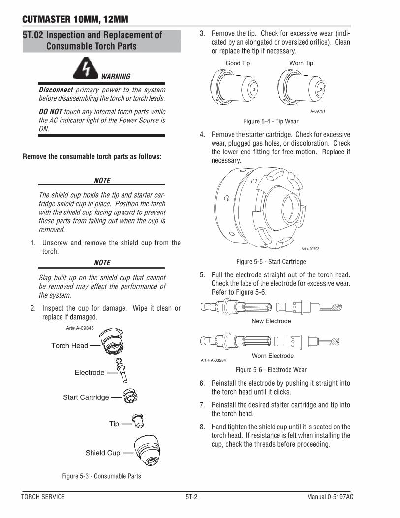
5T.02 Inspection and Replacement of Consumable Torch Parts
WARNING
Disconnect primary power to the system before disassembling the torch or torch leads.
DO NOT touch any internal torch parts while the AC indicator light of the Power Source is ON.
Remove the consumable torch parts as follows:
NOTE
The shield cup holds the tip and starter car-tridge shield cup in place. Position the torch with the shield cup facing upward to prevent these parts from falling out when the cup is removed.
1. Unscrew and remove the shield cup from the torch.
NOTE
Slag built up on the shield cup that cannot be removed may effect the performance of the system.
2. Inspect the cup for damage. Wipe it clean or replace if damaged.
Art# A-09345
Electrode
Start Cartridge
Tip
Shield Cup
Torch Head
Figure 5-3 - Consumable Parts
3. Remove the tip. Check for excessive wear (indi-cated by an elongated or oversized orifice). Clean or replace the tip if necessary.
Good Tip Worn Tip
A-09791
Figure 5-4 - Tip Wear
4. Remove the starter cartridge. Check for excessive wear, plugged gas holes, or discoloration. Check the lower end fitting for free motion. Replace if necessary.
Art A-09792
Figure 5-5 - Start Cartridge
5. Pull the electrode straight out of the torch head. Check the face of the electrode for excessive wear. Refer to Figure 5-6.
Worn Electrode
New Electrode
Art # A-03284
Figure 5-6 - Electrode Wear
6. Reinstall the electrode by pushing it straight into the torch head until it clicks.
7. Reinstall the desired starter cartridge and tip into the torch head.
8. Hand tighten the shield cup until it is seated on the torch head. If resistance is felt when installing the cup, check the threads before proceeding.

CUTMASTER 10MM, 12MM
Manual 0-5197AC 6-1 PART LIST
SECTION 6: PARTS LIST
C. Ordering InformationOrder replacement parts by part number and complete description of the part or assembly, as listed in the parts list for each type item. Also include the model and serial number of the torch. Address all inquiries to your authorized distributor.
6.02 Power Source Replacement Parts Item # Qty Description Catalog #
1 1 Logic PCB assembly 10mm & 12mm 9-0076 2 1 Control PCB assembly 10mm 9-7555 2 1 Control PCB assembly 12mm 9-0077 3 1 Main PCB assembly 10mm 9-7556 3 1 Main PCB assembly 12mm 9-0079 4 1 Air Regulator 10mm & 12mm 9-0081 5 1 Solenoid assembly 10mm & 12mm 9-0082 6 1 Pressure Switch 10mm & 12mm 9-0075 7 1 Hall Current Sensor 10mm & 12mm 9-0088 8 1 ON/OFF Switch 10mm & 12mm 9-0074 9 1 Cooling Fan 10mm & 12mm 9-0042 10 1 Input Rectifier 10mm & 12mm 9-0049
5
2
1
3
10
7
9
8
6
4
Art# A-10400
Parts 6-1 - Power Source
6.01 Introduction
A. Parts List Breakdown
The parts list provides a breakdown of all replaceable components.
B. Returns
If a product must be returned for service, contact your distributor. Materials returned without proper authorization will not be accepted.
CUTMASTER 10MM, 12MM
PART LIST 6-2 Manual 0-5197AC
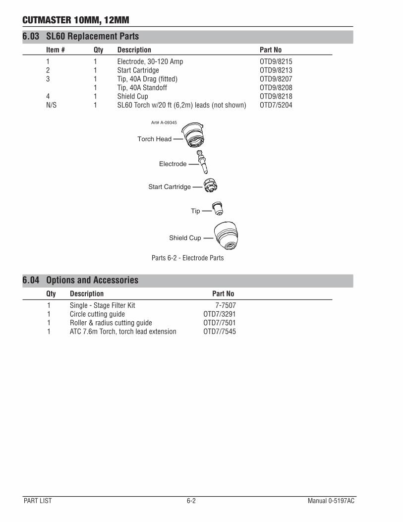
6.03 SL60 Replacement Parts Item # Qty Description Part No
1 1 Electrode, 30-120 Amp OTD9/8215 2 1 Start Cartridge OTD9/8213 3 1 Tip, 40A Drag (fitted) OTD9/8207 1 Tip, 40A Standoff OTD9/8208 4 1 Shield Cup OTD9/8218 N/S 1 SL60 Torch w/20 ft (6,2m) leads (not shown) OTD7/5204
Art# A-09345
Electrode
Start Cartridge
Tip
Shield Cup
Torch Head
Parts 6-2 - Electrode Parts
6.04 Options and Accessories Qty Description Part No
1 Single-StageFilterKit 7-7507 1 Circle cutting guide OTD7/3291 1 Roller & radius cutting guide OTD7/7501 1 ATC 7.6m Torch, torch lead extension OTD7/7545
CUTMASTER 10MM, 12MM
Manual 0-5197AD A-1 APPENDIX
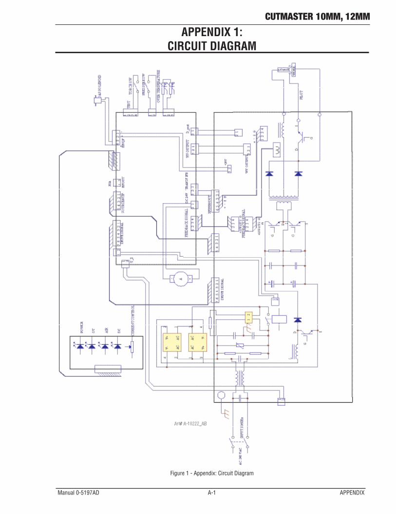
APPENDIX 1: CIRCUIT DIAGRAM
Figure 1 - Appendix: Circuit Diagram
Statement of Warranty
LIMITED WARRANTY: Subject to the terms and conditions established below, Thermadyne Company warrants to the original retail purchaser that new Thermal Dynamics CUTMASTER® plasma cutting systems sold after the effective date of this warranty are free of defects in material and workmanship. Should any failure to conform to this warranty appear within the applicable period stated below, Thermadyne Company shall, upon notification thereof and substantiation that the product has been stored operated and maintained in accordance with Thermadyne’s specifications, instructions, recommendations and recognized industry practice, correct such defects by suitable repair or replacement.
This warranty is exclusive and in lieu of any warranty of merchantability or fitness for a particular purpose.
Thermadyne will repair or replace, at its discretion, any warranted parts or components that fail due to defects in material or workmanship within the time periods set out below. Thermadyne Company must be notified within 30 days of any failure, at which time Thermadyne Company will provide instructions on the warranty procedures to be implemented.
Thermadyne Company will honor warranty claims submitted within the warranty periods listed below. All warranty periods begin on the date of sale of the product to the original retail customer or 1 year after sale to an authorized Thermadyne Distributor.
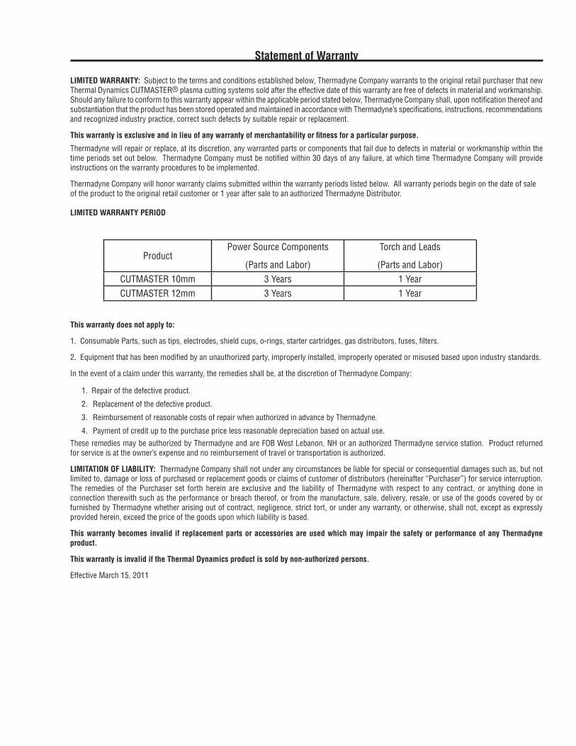
LIMITED WARRANTY PERIOD
ProductPower Source Components
(Parts and Labor)
Torch and Leads
(Parts and Labor)CUTMASTER 10mm 3 Years 1 YearCUTMASTER 12mm 3 Years 1 Year
This warranty does not apply to:
1. Consumable Parts, such as tips, electrodes, shield cups, o-rings, starter cartridges, gas distributors, fuses, filters.
2. Equipment that has been modified by an unauthorized party, improperly installed, improperly operated or misused based upon industry standards.
In the event of a claim under this warranty, the remedies shall be, at the discretion of Thermadyne Company:
1. Repair of the defective product.
2. Replacement of the defective product.
3. Reimbursement of reasonable costs of repair when authorized in advance by Thermadyne.
4. Payment of credit up to the purchase price less reasonable depreciation based on actual use.
These remedies may be authorized by Thermadyne and are FOB West Lebanon, NH or an authorized Thermadyne service station. Product returned for service is at the owner’s expense and no reimbursement of travel or transportation is authorized.
LIMITATION OF LIABILITY: Thermadyne Company shall not under any circumstances be liable for special or consequential damages such as, but not limitedto,damageorlossofpurchasedorreplacementgoodsorclaimsofcustomerofdistributors(hereinafter“Purchaser”)forserviceinterruption.The remedies of the Purchaser set forth herein are exclusive and the liability of Thermadyne with respect to any contract, or anything done in connection therewith such as the performance or breach thereof, or from the manufacture, sale, delivery, resale, or use of the goods covered by or furnished by Thermadyne whether arising out of contract, negligence, strict tort, or under any warranty, or otherwise, shall not, except as expressly provided herein, exceed the price of the goods upon which liability is based.
This warranty becomes invalid if replacement parts or accessories are used which may impair the safety or performance of any Thermadyne product.
This warranty is invalid if the Thermal Dynamics product is sold by non-authorized persons.
Effective March 15, 2011

Thermadyne USA2800 Airport RoadDenton, TX 76207 USATelephone: (940) 566-2000800-426-1888Fax: 800-535-0557Email: [email protected]
Thermadyne Canada2070 Wyecroft RoadOakville, OntarioCanada, L6L5V6Telephone: (905)-827-1111Fax: 905-827-3648
Thermadyne EuropeEurope BuildingChorley North Industrial ParkChorley, LancashireEngland, PR6 7BxTelephone: 44-1257-261755Fax: 44-1257-224800
Thermadyne, ChinaRM 102A685 Ding Xi RdChang Ning DistrictShanghai, PR, 200052Telephone: 86-21-69171135Fax: 86-21-69171139 PT. Thermadyne Utama IndonesiaJl. Angsana II Blok AE No. 28Delta Silicon I, Cikarang - SukaresmiBekasi, 17550IndonesiaTel: +62 21 8990 6095Fax: +62 21 8990 6096 / 1867http://www.thermadyne.com
Thermadyne Asia Sdn BhdLot 151, Jalan Industri 3/5ARawang Integrated Industrial Park - Jln Batu Arang48000 Rawang Selangor Darul EhsanWest MalaysiaTelephone: 603+ 6092 2988Fax : 603+ 6092 1085
Cigweld, Australia71 Gower StreetPreston, VictoriaAustralia, 3072Telephone: 61-3-9474-7400Fax: 61-3-9474-7510
Thermadyne ItalyOCIM, S.r.L.Via Benaco, 320098 S. GiulianoMilan, ItalyTel: (39) 02-98 80320Fax: (39) 02-98 281773
Thermadyne International2070 Wyecroft RoadOakville, OntarioCanada, L6L5V6Telephone: (905)-827-9777Fax: 905-827-9797
GLOBAL CUSTOMER SERVICE CONTACT INFORMATION

Asia Pacific Regional Headquarters71 Gower StreetPreston, Victoria, Australia, 3072Telephone: +61 3 9474 7400FAX: +61 3 9474 7391Email: [email protected]