
Plants 3 & 6 PHA Revalidation - Boiler Feedwater & Utility Steam ...
38
Kenai Nitrogen Operations K00S52R1 Plants 3 & 6 Boiler Feed Water and Utility Steam Systems: 7, 8, 9, 42, 52, 56, 57, 58 Process Hazards Analysis Revalidation Final Report February 7, 2002 Prepared by: Kenai Nitrogen Operations Mile 21 Kenai Spur Hwy Kenai, Alaska 99611 Project No.: K00S52R1
-
Upload
nguyenliem -
Category
Documents
-
view
236 -
download
2
Transcript of Plants 3 & 6 PHA Revalidation - Boiler Feedwater & Utility Steam ...

Kenai Nitrogen Operations K00S52R1 Plants 3 & 6 Boiler Feed Water and Utility Steam Systems: 7, 8, 9, 42, 52, 56, 57, 58 Process Hazards Analysis Revalidation Final Report February 7, 2002
Prepared by:
Kenai Nitrogen Operations Mile 21 Kenai Spur Hwy
Kenai, Alaska 99611
Project No.: K00S52R1

Kenai Nitrogen Operations PHA Revalidation - Final Report Kenai Plant 3/6 Boiler Feed Water & Utility Steam Systems: 7,8,9,42,52,56,57,58 February 7, 2002
Page 2
TABLE OF CONTENTS
SECTION 1.0 ABOUT THIS STUDY ..............................................................................................................…3 Methodology....................................................................................................................................3 Baseline PHA...................................................................................................................................3 Revalidation.....................................................................................................................................4 Other Issues… .................................................................................................................................6 Compliance with OSHA Rule 1910.119 and EPA RMP Rule ........................................................6 Process Hazards Analysis Team......................................................................................................7 Process Description .........................................................................................................................8 Study P&IDs list ............................................................................................................................35 Other Available PSI…...................................................................................................................36 SECTION 2.0 RECOMMENDATIONS ............................................................................................................36 SECTION 3.0 STUDY WORKSHEETS & ATTACHMENT..........................................................................39 Attachment 1 – Revalidation Agenda Attachment 2 – Initial PHA Content Checklist Attachment 3 – Baseline PHA Screening Checklist Attachment 4 – Discussion of Recommendations from Baseline PHA Attachment 5 – Change Evaluation Checklist to Identify Undocumented Changes Attachment 6 – Operations Change Evaluation and Wrap-up Checklist Attachment 7 – Maintenance Change Evaluation and Wrap-up Checklist Attachment 8 – Engineering Change Evaluation and Wrap-up Checklist Attachment 9 – Inspection Change Evaluation and Wrap-up Checklist Attachment 10 – Emergency Response Change Evaluation and Wrap-up Checklist Attachment 11 – Safety Group Change Evaluation and Wrap-up Checklist Attachment 12 – General Change Evaluation and Wrap-up Checklist Attachment 13 – Human Factors Issues/Checklist Attachment 14 – Previous Incident Reports Checklist Attachment 15 – Evaluate Potential Off-Site Consequences Worksheet Attachment 16 – Additional Areas "What-If" Worksheets Attachment 17 – Revalidation Guideword Checklist Attachment 18 – Risk Ranking Matrix

Kenai Nitrogen Operations PHA Revalidation - Final Report Kenai Plant 3/6 Boiler Feed Water & Utility Steam Systems: 7,8,9,42,52,56,57,58 February 7, 2002
Page 3
1.0 ABOUT THIS STUDY The Process Hazards Analysis, K00S0052 conducted between November 12, 1996 and February 14, 1997 was revalidated at Agrium's Kenai Nitrogen Operations December 11-14, 2001. The original PHA, as well as the revalidation, focused on the plants Boiler Feed Water and Utility Steam (Systems 7,8,9,42,52,56,57,58) EPA RMP 40 CFR Part 68 Section 112 (7) and OSHA Rule 1910.119, "Process Safety Management of Highly Hazardous Chemicals" requires that the initial Process Hazard Analysis (PHA) for a covered process be updated and revalidated by a knowledgeable team at least every five years. The objective of PHA revalidation is to assure that the PHA is consistent with the current process. The PHA is revalidated, by evaluating and addressing the following questions:
• Have significant new hazards been created or introduced into the process? • Has the possible occurrence of a catastrophic release in the process unit become
significantly more likely? • Have consequences of previously identified toxic or flammable material releases become
more severe? • Have consequences that could go "off-site" been identified? • Have previously identified safeguards become compromised or challenged?
METHODOLOGIES
Baseline PHA
The original, or baseline, PHA was conducted primarily using the "WHAT-IF" technique. WHAT-IF Technique
The "What-If" technique involves asking questions that require the team to analyze deviations from the procedure. An example is, "What-If"…the drying step were left out of the procedure?" The team then develops consequences of this action (or inaction) and documents the safeguards in a manner similar to HAZOP. The "What-If" scenario is then ranked for risk, and recommendations are made if appropriate, similar to the HAZOP technique.
Revalidation
The PHA procedure used to revalidate Plants 3/6 Boiler Feed Water and Utility Steam Systems was the Guideword/Checklist PHA Revalidation Method. This methodology was organized into the following tasks, and are described below:
1. Collection of Information 2. Information Review 3. Revalidation Study Sessions (with PHA Team) Collection of Information
The following information was collected prior to the Revalidation Study Sessions:

Kenai Nitrogen Operations PHA Revalidation - Final Report Kenai Plant 3/6 Boiler Feed Water & Utility Steam Systems: 7,8,9,42,52,56,57,58 February 7, 2002
Page 4
1. Baseline PHA, including worksheets, Action Item list, P&IDs reviewed, and status of
recommendations. 2. Documented changes to the design or operation of the process since the baseline PHA
(including MOCs). 3. Documented incident reports from this unit. 4. Latest revision of Piping and Instrument Diagrams (P&IDs) that describe the process. 5. Other Process Safety Information, such as PRV design basis and data and Standard
Operating Conditions and Limits (SOCLs). Information Review
The collected information was reviewed by the Revalidation Team Leader and PSM Assistant prior to the study dates. The purpose of the Information Review is to screen the baseline PHA for content and quality, and to identify concerns and issues that need to be reviewed by the Revalidation Team during the study sessions. This resulted in the generation of an agenda or work plan for the sessions. The Information Review included the following tasks required to identify items for discussion with the team:
1. Review the baseline PHA and complete the Initial PHA Content Checklist, see Attachment 2, and the Baseline PHA Screening Checklist, see Attachment 3. Evaluate the baseline PHA to ensure that off-site consequences were adequately discussed and addressed.
2. Review and verify the documented status of recommendations from the baseline PHA and any project PHAs affecting this unit.
3. Review all incidents occurring in the system since the baseline PHA, and develop a list of those pertinent to the revalidation process.
4. Develop a list of all changes that have occurred to the design or operation of the process since the baseline PHA, see Attachment 5. This is done by comparing the latest P&IDs with the P&IDs reviewed during the baseline PHA, and by reviewing those changes to the design or operation of the process that have been analyzed by the MOC process.
5. Develop an agenda, or work plan for the study sessions, see Attachment 1.
Revalidation Study Sessions (with PHA Team)
The revalidation study was discussed and prepared by a multi-disciplined team knowledgeable in the process and in the PHA method used. At the beginning of the session, the Team Leader reviewed the PHA revalidation scope and purpose, and reviewed the completion of the Initial PHA Content Checklist and the Baseline PHA Screening Checklist. The group was then lead through the revalidation procedure, which included:
1. General discussion regarding the status of open recommendations from the baseline PHA, see Attachment 4;
2. Work through the Change Evaluation Checklist to identify undocumented changes, see Attachment 5;
3. Work through the Operations Change Evaluation and Wrap-up Checklist Issues, see Attachment 6;
4. Work through the Maintenance Change Evaluation and Wrap-up Checklist Issues, see

Kenai Nitrogen Operations PHA Revalidation - Final Report Kenai Plant 3/6 Boiler Feed Water & Utility Steam Systems: 7,8,9,42,52,56,57,58 February 7, 2002
Page 5
Attachment 7;
5. Work through the Engineering Change Evaluation and Wrap-up Checklist Issues, see Attachment 8;
6. Work through the Inspection Change Evaluation and Wrap-up Checklist Issues, see Attachment 9;
7. Work through the Emergency Response Change Evaluation and Wrap-up Checklist Issues, see Attachment 10;
8. Work through the Safety Group Change Evaluation and Wrap-up Checklist Issues, see Attachment 11;
9. Work through the General Change and Wrap-up Checklist Issues, see Attachment 12; 10. Review Human Factors Issues/Checklist, see Attachment 13; 11. Discuss Previous Incident Reports, see Attachment 14; 12. Evaluate Potential Off-Site Consequences, see Attachment 15; 13. Discuss Additional Areas "What-If" Worksheets, see Attachment 16; 14. Review Revalidation Guideword Checklist, see Attachment 17; 15. Review Risk Ranking Matrix, see Attachment 18.
"What-If" - The team utilized the "What-If" technique to identify potential hazards and areas of concern when it was determined that those hazards or concerns were not adequately addressed by the baseline PHA, such as potential off-site consequences. The "What-If" technique was also utilized to evaluate potential hazards caused by new or modified equipment as the review team deemed appropriate. OSHA recognizes the "What-If" as an acceptable method of evaluating process hazards. Those scenarios evaluated using the "What-If" technique can be found in Attachments 15 and 16. The "What-If" technique involves asking questions that require the team to analyze deviations from the design intent. An example is: "What-If...the drying step were left out of the procedure?" The team then develops consequences of this action (or inaction) and documents the safeguards in a manner similar to HAZOP. The "What-If" scenario is then ranked for risk, and recommendations are made if appropriate, similar to the HAZOP technique. Attachment 18 shows the criteria for applying risk rankings to various scenarios.

Kenai Nitrogen Operations PHA Revalidation - Final Report Kenai Plant 3/6 Boiler Feed Water & Utility Steam Systems: 7,8,9,42,52,56,57,58 February 7, 2002
Page 6
Other Issues
Facility Siting – Agrium Kenai Nitrogen Operations has completed a plant-wide facility siting study, which adequately addresses those issues; therefore, the Facility/Plant Siting Issues checklist was not utilized.
Compliance with OSHA Rule 1910.119 and EPA RMP Rule
This study complies with OSHA rule 1910.119, "Process Safety Management of Highly Hazardous Chemicals" and EPA 40CFR Part 68 Section 112, "Risk Management Program." In particular, this study complies with paragraph (e,6) of the OSHA rule that states; "At least every five years after the completion of the initial process hazard analysis. The process hazard analysis shall be updated and revalidated by a team, meeting the requirements in paragraph (e)(4) of this section to assure that the process hazard analysis is consistent with the current process." The study also complies with Subpart D (68.67) of the RMP Rule covering the same requirements as OSHA 1910.119 and potential off-site consequences. The study was completed within five years of the baseline PHA. A multi-disciplined team, including at least one person with knowledge and experience in the process, discussed and prepared the study in a manner to ensure that the baseline PHA is consistent with the current process.

Kenai Nitrogen Operations PHA Revalidation - Final Report Kenai Plant 3/6 Boiler Feed Water & Utility Steam Systems: 7,8,9,42,52,56,57,58 February 7, 2002
Page 7
Process Hazards Analysis Team (e, 4)
The PHA Revalidation was discussed and prepared by a team with expertise in engineering and operations, with at least one employee having specific expertise in the process being evaluated. The Process Hazards Analysis Revalidation was conducted between December 11 and December 14, 2001 at Agrium Kenai Nitrogen Operations in Kenai, Alaska.
The study team consisted of the following people:
Name Title Years of Experience Ed Aisenbrey PSM Coordinator, PHA Team Leader 24 Russell Peterson Chemical Engineer, P&C Supervisor 26 Keith Chilson Plant 3/6 A Operator 9 America Dukowitz PSM Assistant, PHA Scribe 4 Michelle Grzybowski Environmental Specialist 7 David Hunter Plant 4 A Operator 13 Bruce Jackman Maintenance Engineer 8 Forrest Pipkin Mechanical Engineer 2 Jamie Query Plant 1 A Operator 8 Jeff Turkington Plant 1 Unit Coordinator 22 Jeff Laube Plant 1 B Operator 2.5 Raymond Hanson Chemical Engineer 15 Dana Bassel Safety Specialist 31 Joe Pault PDM 26 Dwayne Goche Inspection Rep 17

Kenai Nitrogen Operations PHA Revalidation - Final Report Kenai Plant 3/6 Boiler Feed Water & Utility Steam Systems: 7,8,9,42,52,56,57,58 February 7, 2002
Page 8
Process Description SYSTEM PURPOSE and DESCRIPTION: The main function of a boiler is to take clean demineralized water and heat it to a temperature above moisture saturation at a given pressure. Steam is used in the process and as a power source for turbines, which in turn run fans, pumps, compressors, etc., and as a heat source for tracing and heating of water. Steam is used at varying pressures throughout the plant. There are three main steam headers, 1500 psig, 550 psig, and 50 psig. 1500 psig steam and 50 psig steam are generated from the waste heat off the ammonia plants' process. The 550 psig steam is generated in package boilers at the Utility Plant and is also let down from the 1500 psig system. 550 psig steam is also generated in the waste heat system, and this steam is dedicated to the NH3 plants' process. Although the plants are generally spoken of as being separate, they are however intertied in almost every utility, steam in particular. The process of boiling water to make steam is a familiar phenomenon. Thermodynamically, boiling is the result of adding heat to the working substance, water, in a constant-pressure and constant-temperature process. The heat which must be supplied to change water into steam without raising its temperature is called the heat of evaporation or vaporization. EQUIPMENT:
3B600A PACKAGE BOILER System 08 The 3B600A Package Boiler was manufactured by Union Iron Works and is a 100,000 lb/hr water tube boiler that is fired by natural gas and is an "A" type boiler. It has a steam-driven forced draft fan and shares a common exhaust stack with 3B600B boiler. This is the only boiler that is set up to burn waste fuels. This boiler can hold approximately 4000 gallons of water, which is supplied to the boiler from the 1F105 Deaerator in Plant 1 by Low Pressure Boiler Feed Water Pumps 1G103A/B/C at about 950 psig. The water goes through steam drum level control valve 3FC3004 that has a manual block valve on each side of it and a bypass around it. Upstream of this valve is a set of orifice flanges where 3FIT3004B measures the feed water flow. This signal goes to the 3FRC3004 which is the controller that actually controls the feed water valve 3FC3004. This is a cascade control loop and has three factor's input to control and anticipate process changes to insure a proper drum level. The three factors are primarily level and then feed water flow and steam flow. The feed water valve, feed water flow transmitter, and steam flow transmitter are all located outside. All piping is insulated and steam traced. Transmitters are housed in boxes to keep them from freezing during the winter months. Care should be taken to insure no leaks exist and that steam tracing is always on to insure accurate reading. As the water leaves the control valve, it goes through a check valve and block valve that also has a small ¾" bypass valve to aid in startup. The water then goes to the Economizer to be preheated by the exhaust flue gas from the boiler. The water is on the tube side, and the exhaust goes around the finned tubes. The water is then introduced into the steam drum on the east end of the boiler. As the boiler is operating, it is heating the water in the innermost tubes, and as heat rises, it will naturally circulate and evaporate, making steam under pressure. The water rising in the hotter tubes are called risers; the tubes farthest away from the fire are called downcomers. Any water droplets that are still left in the steam are separated out in the steam drum by baffles. The floating solids and contaminants are removed by a continuous blowdown located at the normal water level. Other heavier solids in the water will circulate through the boiler until

Kenai Nitrogen Operations PHA Revalidation - Final Report Kenai Plant 3/6 Boiler Feed Water & Utility Steam Systems: 7,8,9,42,52,56,57,58 February 7, 2002
Page 9
it settles to the bottom drum or mud drum to be blown out intermittently. The steam is taken off the top of the steam drum after passing through the baffles as saturated steam and goes through the crossover pipe that is connected to the superheater section of the boiler. This section is a separate set of tubes in the southwest corner of the boiler, in the path of the exhaust flue gas, to superheat the dry steam to about 650°F for additional H.P. The steam exits the superheater section and goes through the non-return valve and manual block valve and into the 550 psig steam header. Upstream of the non-return valve is the superheater manual vent used for startup and shutdown to keep a cooling flow constantly through the superheater tubes. If a flow is not maintained at all times, damage may occur to the tubes from excess heat. Also, on the exit pipe between the superheater and non-return valve is the superheater relief valve 3PSV3007. There are two relief valves on the steam drum 3PSV3004 (east valve) and 3PSV3005 (west drum valve). These relief valves are sized and designed to vent the pressure in the boiler should something happen. All steam relief valves on package boilers are set in the shop, but must be checked while on line. Downstream of the outlet block valves is another set of orifice flanges that transmits a steam flow signal to the control room (3FIT3004A) Water quality is very important to boiler operation. One of the controlling factors of quality is blowdown. Mud drum blowdown is done normally once per shift; this draws sediments off the bottom of the mud drums. A continuous blowdown draws at the water surface level in the steam drum to keep any floating debris out of the boiler and to prevent any priming or carryover. All blowdown water is passed on to the 1F102 Blowdown Tank in Plant 1. Blowdown from the boilers may be sent to 1F103 Blowdown Tank, located between 3B600A and 3B600B. When 1F102 is out of service, this tank vents to atmosphere and drains to the sewer. Samples of the continuous blowdown are collected every 12 hours and analyzed for pH, conductivity, and PO4. These factors are controlled by the amount of blowdown and the amount of additive to the water. Tri-sodium and di-sodium phosphate are injected in the steam drum by 3G638A pump, taking suction from 1F146 Chemical Tank. These chemicals are mixed every 24 hours, and the amounts are determined by the sample results. At the east end of the steam drum are the visual sight glasses and a level column that contains the alarm probes. Ideally, the level should run in the middle of the steam drum and is known as 0 inches or 50 percent. As the level rises, it will be measured by inches. If the water touches the high level probe in the water column, it will sound an alarm to that effect. This will warn the operator of the possibility of carrying water over into the superheater, and thereby collapsing the 550 psig steam header. As the level falls and exposes the low water probe, it will sound an alarm as well. If the water continues to fall and exposes the low water cut-out probe, this will shut down the boiler. A manual low water override exists to keep the boiler operating when the level is still high enough for safe operation but below the trip point. The low level override button is there primarily to blow down the water column and sight glasses. Also located on the east end of the steam drum are the taps for the drum level transmitter, 3LIT3012. This signal goes into the control room and out to the feed water control valve. Air for combustion in the boiler is supplied by 3GT617A forced draft fan that is driven by a 550 psig turbine. The turbine uses about 5200 lb/hr steam at 4500 rpm. The 3GB617A fan can put out 30,400 scfm of air and is controlled by a set of louvers from either the control room or manually out in the field. There are two more sets of louvers located in the throat of the boiler where the wind box meets the firebox. These two sets of louvers at present are locked in place and are not to be moved. They are set to move the air in a swirling pattern to properly mix the fuel for complete combustion and position the flame in the firebox without impinging upon the riser tubes. The amount of combustion air is regulated by the Bailey positioner controlled from the board. The amount of air to gas is adjusted so that in automatic, there will only be 2% excess oxygen in the stack. The air flow is measured by taking a differential pressure drop across the boiler. The high pressure tap is at the back of the boiler on the furnace box, and the low pressure tap is located above the economizer in the outlet to the stack. There is also a tap on the exhaust going to the oxygen analyzer that allows us to determine if fuel gas mixture is proper by taking a sample of the exhaust, analyzing it, and recording the result on the control board. There is a

Kenai Nitrogen Operations PHA Revalidation - Final Report Kenai Plant 3/6 Boiler Feed Water & Utility Steam Systems: 7,8,9,42,52,56,57,58 February 7, 2002
Page 10
minimum air flow switch, PS3046, located on the wind box that must be satisfied before the boiler can be lit, to indicate that the fan is indeed running at a proper speed. If the FD fan should fail, this pressure switch will also shut down the boiler firing. There is a set of louvers located just under the economizer that is normally left wide open, but could be used to vary the temperature in the superheater section which would also have an effect throughout the boiler. And finally, there is a set of isolation louvers in the outlet ducting just before the exhaust goes into the combined stack that is used for isolating this boiler when shut down from 3B600B that still may be on line. Methane or natural gas is used for fuel in all of the package boilers and is supplied to the Utility Plant from the fuel gas header at 120 psig by PIC395 on the flare gas header and by PCV109 on the K-Beach gas header. This pressure is let down by a regulator, PCV350, at what is known as the gas tree south of 3B600B. The regulator lets the natural gas down to 10 psig. There is sufficient valving to be able to take this regulator out even while on line by manually blocking in upstream and downstream valves while using gas around it through a bypass valve. The gas then goes through a set of orifice flanges where a transmitter, 3FIT3003A, is located to send a signal to the amount of gas flow to be indicated. Just downstream from the pressure transmitter is the low gas trip, 3PA3042. It will shut down the boiler in the event of low gas pressure. The gas then goes to the pilot valve and the main control valve. The pilot is also pressure regulated at 3PCV3051, set at 1 psig, and has two small solenoid valves that are activated by the boiler start controls to open during the start sequence. The manual pilot block valve must be opened before starting the boiler, and then closed when complete. The gas control valve operates the gas flow to the boiler once the two safety Maxon valves are open and the downstream manual block valve is open. The safety Maxons are also controlled by the boiler control panel in the startup sequence. The Maxons are electromagnetic, in that an electric signal is given to them that overcomes a spring load. If for some reason the electric signal is removed by the shutdown system, they will go closed, making them safety valves. A third Maxon also works in conjunction with these two to vent any gas pressure trapped between them to atmosphere when the boiler trips or is shut down. Downstream from the Maxon valves on the piping to the burner is a high pressure trip switch, 3PS3020, set at 9 psig to shut down the boiler firing should the pressure at this point get that high or the gas regulator malfunctions.
3E600A ECONOMIZER System 08 3E600A receives its water from the 1F105 Deaerator (DA) where oxygen is stripped from the water and preheated to around 230°F. Oxygen scavenger is also injected into the storage section to prevent any oxygen from collecting on the tubes of the Economizer and boiler. Once the water leaves the DA section, it enters the Low Pressure Boiler Feed Water (BFW) Pumps 1G103A or B, where it is pumped to the boiler at pressures up to 950 psig. The flow into 3B600C is controlled by 3FCV328. The flow into 3B600B is controlled by 3FCV3002, and the flow into 3B600A is controlled by 3FCV3004 where the water enters the top of the Economizers and exits out the bottom. The water enters the steam drum on 3B600A/B and the mud drum on 3B600C after leaving the Economizer. The Economizer is a BFW preheater that is located downstream of the BFW Control Valve. Its purpose is to increase the temperature of the water before it is introduced to the drum of the boiler. The flue gas, as it starts up the stack, flows around the fined Economizer tubes. The temperature of BFW ahead of the Economizer is about 220°F and about 375°F at the inlet to the drum. The Economizer greatly improves the efficiency of the boiler by utilizing heat that would otherwise be lost up the stack to the atmosphere. An economizer is a device for using some of the flue-gas heat, that would otherwise go to waste, by pumping boiler feed water through banks of tubes placed in the direct path of the gas passing to the boiler chimney where the economizer is located. Boiler feed water is under a higher pressure than boiler pressure and can be heated to a much higher temperature than is possible when feed water is heated at or near atmospheric pressure.

Kenai Nitrogen Operations PHA Revalidation - Final Report Kenai Plant 3/6 Boiler Feed Water & Utility Steam Systems: 7,8,9,42,52,56,57,58 February 7, 2002
Page 11
Cast iron pipe was formerly used in practically all economizer construction because cast iron resists corrosion better than steel. This type of economizer is still suitable for low or medium pressures, but cast iron is not reliable under the higher boiler pressures now in common use. Therefore, steel pipe construction is standard practice in high pressure boiler installations, with deaerators to rid feed water of air and other corrosive gases before it enters the economizer. Economizers offer considerable resistance to the passage of flue gas, and therefore some form of mechanical draft must be installed when they are used. They take up space, add to the initial cost of installation, and involve extra maintenance cost for cleaning and repair. On the other hand, economizers may effect quite a large saving in fuel consumption since a 50° temperature increase saves about 5 percent of the fuel. They increase boiler efficiency substantially when boilers are operated at a high percentage over normal rating. Higher feed water temperatures tend to reduce boiler stresses.
3C600 PACKAGE BOILER STACK System 08 The 3C600 Package Boiler Stack or Chimney for the 3B600A/B boiler has a height of 90 feet, is 13 feet at the base, and is constructed of steel. The ducting from the Economizers outlet runs over and ties into this common stack. There are louvers at the bottom of the Economizer and louvers at the inlet of the stack. Natural draft is produced by a chimney alone. It is caused by the difference in weight between the column of hot gas inside the chimney and a column of cool outside air of the same height and cross-section. Being much lighter than outside air, chimney gas tends to rise, and the heavier outside air flows in through the furnace to take its place. The 3B600 boilers operate a forced draft fan which forces air into the boiler furnace. With forced draft, the pressure within the furnace is often higher than atmospheric pressure, 14.7 at sea level. The main reason for a chimney, and why we operate a force draft fan, is that it discharges the products of combustion at such a height that it will not become a nuisance to the surrounding community.
3GT617A 3GB617A
3B600A FORCED DRAFT FAN AND DRIVER System 08
For a description on the forced draft fan and driver, see 3B600A Package Boiler in Activity 03.
3GG617A FD FAN GEAR BOX System 08 3F617A FD Fan Gear Box is located next to the squirrel cage on 3B600A. The gearbox was installed to reduce the speed of the fan. Without this reduction rate, the fan would operate at too high of a flow rate for the boiler. The turbine normally operates at 4250 rpm, but with the gearbox, the fan operating speed is greatly reduced to around 1800 rpm, giving the turbine-to-fan about a 2.5 reduction ratio.
3F677 LUBE OIL RESERVOIRS (3B600A) System 08 3F677 3F678 are Lube Oil Reservoirs attached to 3B600A turbine. 3F677 reservoir supplies oil to the 3F617A gearbox, and 3F678 supplies oil to the 3GT617A turbine. Both reservoirs are similar in size and hold around 10–15 gallons of oil. Both reservoirs have dipsticks for routine monitoring of the levels.
3F678 LUBE OIL RESERVOIR System 08 For a description of this equipment, see 3F677 Lube Oil Reservoir in Activity 03.

Kenai Nitrogen Operations PHA Revalidation - Final Report Kenai Plant 3/6 Boiler Feed Water & Utility Steam Systems: 7,8,9,42,52,56,57,58 February 7, 2002
Page 12
3F679 MECHANICAL FILTERS System 08 3F679 Filter is located downstream of the oil pump and was installed to keep the oil that is circulating throughout the gearbox clean. 3F680 Filter is located above the 3F678 Reservoir and was installed to keep the oil that is circulating throughout the turbine section clean. Both of these filters are located on 3GT617A Turbine and are of the automotive screw-on type. These filters were installed to remove any solid particles that may be floating about in the oil and help prolong the life of the equipment.
3F680 MECHANICAL FILTER System 08 For a description of this equipment, see 3F679 Mechanical Filter in Activity 03.
3E624 LUBE OIL COOLER System 08 3E624 Lube Oil Cooler is designed so that the gear case (3GG617A) oil temperature is maintained around 100°F. The cooling water enters the tube side of the exchanger with the oil flowing through the shell side. The oil pump draws the oil up from the reservoir and flows through the exchanger where the heat is dissipated. The cool oil enters four different locations on the gearbox, then flows back to the 3F677 reservoir where a continuous cycle takes place. The pressure in this system normally runs 20 psig. There is a relief valve just downstream of the pump set to relieve back into the tank should the pressure exceed 25 psig. Constant monitoring of the pressure and temperature is essential. Once a month it is routine for the operator to backflush the exchanger to clean out any debris. When backflushing the cooling water, it is important to monitor both the exchangers on this turbine. 3E624 and 3E625 are tied together on the same cooling water line. Also, there are cooling water lines that go directly to the turbine for additional cooling. Should anything break loose and lodge in the line to the other exchanger or the turbine, overheating will occur, causing damage to the equipment.
3E625 LUBE OIL COOLER System 08 3E625 Lube Oil Cooler is designed so that the turbine (3GT617A) inboard and outboard bearing temperatures are maintained around 100°F. The cooling water enters the tube side of the exchanger with the oil flowing through the shell side. The oil pump draws the oil from the reservoir and then through the exchanger where the heat is dissipated. The cool oil enters the two bearings located in the turbine and then flows backs to the 3F678 reservoir, where a continuous cycle takes place. There is a relief valve just downstream of the oil pump that relieves back into the reservoir should the pressure exceed 25 psig. Constant monitoring of the pressure and temperature is essential. Once a month it is routine for the operator to backflush the exchanger to clean out any debris. When backflushing the cooling water, it is important to monitor both the exchangers on the turbine. 3E624 and 3E625 are tied together on the same cooling water line. Also, there are cooling water lines that go directly to turbine for additional cooling. Should anything break loose and lodge in the line to the other exchanger or the turbine, overheating will occur, causing damage to the equipment.
3E618A SAMPLE COOLER System 08 3E618A Sample Cooler is located at the boiler on the west side of the boiler. This cooler is a tube and shell exchanger with the cooling water flowing through the shell side. The boiler water comes out of the steam drum and runs through the tubing where the hot condensate is cooled in the exchanger, allowing the operator to grab a sample of the boiler water. The sample once obtained is tested for pH, conductivity, and phosphate. The sample cooler is an important tool for determining the water analysis of the boiler. Once a shift, the operator will run these samples. Anytime the boiler is blown down or the continuous blowdown is adjusted, it will affect your sample.
3B600B PACKAGE BOILER System 08 Except for a few differences, this boiler is virtually identical with 3B600A boiler. 3B600B uses an electric motor to drive the 3GB617B FD fan; it cannot be used to burn waste fuel at this time. The electric motor on 3B600B is a

Kenai Nitrogen Operations PHA Revalidation - Final Report Kenai Plant 3/6 Boiler Feed Water & Utility Steam Systems: 7,8,9,42,52,56,57,58 February 7, 2002
Page 13
480V Westinghouse, running at 1785 rpm and 100 horsepower. The main breaker for this motor is located in the substation by the HAZMAT Change Room (old S.S. Office). The control panel is a COEN BMS-2000 (Burner Management System) SLC 500 controller processor. The BMS-2000 flame safeguard system utilizes a Bradley SLC-500 industrial duty programmable logic controller. This controller controls all timing, sequencing and safety logic. The controller includes an "electrically erasable programmable read only memory" (EEPROM) for protection against program memory loss. The control panel has the same alarms as the existing panel: High Water, Low Water, High Gas, Low Gas, High Steam Pressure, Low Combustible Air Pressure, Low Instrument Air, and Flame Signal Scanner (fire eye). All of these alarms will be programmed to trip the boiler and annunciate an alarm.
Note: 3B600B will not start if the fan switch is put in Auto. The fan switch must be in the ON position.
3E600B ECONOMIZER System 08 For a description of this equipment, see 3E600A Economizer in Activity 03.
3GB617B 3B600B FORCED DRAFT FAN System 08 For a description on the forced draft fan and driver, see 3B600B Package Boiler in Activity 03.
3E618B SAMPLE COOLER System 08 For a description of this equipment, see 3E618A Sample Cooler in Activity 03.
3B600C PACKAGE BOILER System 08 The 3B600C Boiler was manufactured by Erie City Iron works. It was built in 1969 and is an "O"-type boiler. It is designed to produce 105,000 lb/hr of steam at 550 psig. It is a water tube boiler, fired on natural gas, and has features that make it different from the other package boilers, but none the less, it puts out the same quality superheated steam. Some of the different features are:
a. It has its own short stack. b. It has its superheater section with the tubes running horizontally across the back of the boiler in direct
line with the fire, whereas all the other package boilers have their superheater sections on the southwest corner. The superheater headers run vertical instead of horizontal and are outside of the boiler.
c. It has an external burner ring. This boiler, as well as 3B600A/B, gets its feed water from the Plant 1 DA, 1F105, and is pumped with Low Pressure Boiler Feed Water Pumps 1G103A/B/C to the feed water control valve FCV324 located on the south side of 3B600C, outside. The flow is measured just upstream at an orifice plate and is transmitted to the control room with FT328. The feed water control valve has a block valve on each side of it with a drain on the upstream side with a bypass and block valve around it, so that it can be isolated and removed even if the boiler is on line. Downstream from the feed water valve is a check valve and a chain valve with a small ¾" bypass valve used during startup to control a small amount of this higher pressure water. When the boiler is initially being fired, it has no pressure, and the low pressure feed water is delivered by the 1G103 pumps at about 950 psig and around 230°F, so care must be taken in opening any valve on the feed water line. The feed water enters the top of the economizer that is located in the stack of the boiler to be preheated by the exhaust gases from the boiler. The preheated water comes out the bottom of the economizer and goes into the mud drum on the southeast end. If all of the drains on the mud drum are closed and the ¾" bypass opens around the knocker valves, it will begin to fill the boiler. When the water has filled the mud drum tubes and comes up into the steam drum, it will then be

Kenai Nitrogen Operations PHA Revalidation - Final Report Kenai Plant 3/6 Boiler Feed Water & Utility Steam Systems: 7,8,9,42,52,56,57,58 February 7, 2002
Page 14
necessary to open the atmospheric drain on the southwest corner of the bottom mud drum to establish a flow through the boiler. The incoming water may need to be trimmed back to match the water draining. Located on the steam drum at the east end are the water column and sight glasses. The water alarm column has three probes in it that work by conductivity. When the water level comes up, it will cover the lowest probe, which is the low water cutout and alarm, LLA336, and then continue to fill until it covers low water probe which is alarm LLA335. The level should be maintained above the low water alarm probe. If it were to continue to rise, it would cover the high water probe and give a high water alarm, HLA335. Visual sight glass levels are located on both sides of the water column. Also located on the east end of the steam drum are two taps coming off the drum to the level transmitter that send a signal to the control room board. This is the primary signal for the level control valve or feed water control valve. The feed water valve level controller, FCV328, is part of a cascade control loop that has three signals to maintain steam drum level:
a. Level transmitter (LIT332) b. Steam flow (FIT328B) c. Feed water flow (FIT328A)
The configuration of these three signals allows the FRC to anticipate changes in level by comparing changes in the steam and BFW flows. There is a low water override button that has been provided for blowing down sight glasses and/or water column. It should not be used or jumped out if you don't have any visual or transmitted level indication and don't know where the level is. No water in the steam drum and water tubes can cause severe damage. The forced draft fan is driven with a Turbodyne, 550 psig steam turbine, that has about 115 hp at 4950 rpm. It uses about 7000 lb/hr 550 psig steam. There is a gearbox between it and the fan so that the fan speed is about 1800 rpm and puts out somewhere around 30,400 scfm of air. The lube oil temperature should be maintained at about 100°F. The turbine speed is maintained by a Woodward governor. The 550 psig turbine exhausts to the 50 psig steam header with a relief valve, 3PSV350, on the discharge of the turbine set at 75 psig. As was mentioned, this boiler is the only one that has its forced draft fan outside. But just as 3B600A&B, it pulls some of its air from the building. During cold weather, care must be taken with the temperature while shut down and while trying to start up. The fan has suction louvers that control the volume of air that passes through it into the wind box by the Bailey controller, 3FCV327B. This controller gets its signal from the boiler master or Air Controller, 3FIC327, on the board in the Utility Control Room. Within the wind box on the throat of the boiler is a set of inner or secondary louvers that surround the burner spuds and are set and remain stationary to introduce the air in a swirling pattern, where it is mixed with the gas at the burner tips to get good combustion, such that all of the gas and most of the air is burned in the boiler furnace box before exiting. The ratio of gas to air is about 10 parts air to one part gas with about 2% oxygen left in the boiler stack. Located on the wind box is a low pressure trip switch, PS407, set at .45" of H2O, so that if we lose the FD fan, the boiler will shut down. Also located on the wind box is the high pressure tap of the Air Flow Transmitter, FT329. The low pressure tap is on the stack above the economizer. This allows a D/P pressure drop to be converted to air flow through the boiler and transmitted to the board on FIC327. The tap for the oxygen analyzer is on the stack, also above the economizer, and is transmitted by AT301A to the control room board on AR301A and combustibles by AT301B to AR301B on the control board.

Kenai Nitrogen Operations PHA Revalidation - Final Report Kenai Plant 3/6 Boiler Feed Water & Utility Steam Systems: 7,8,9,42,52,56,57,58 February 7, 2002
Page 15
Note: There are two trips that have been disconnected on this boiler and are not used: one is PS405 high steam pressure switch that would also sound alarm PAH405 on the panalarm, and PS414 steam pressure switch on the turbine that would also ring alarm PA414 on panalarm in the utility control room on 3B600C Boiler. Natural gas is supplied to 3B600C Boiler from the same fuel gas header as 3B600A&B. It comes from 1PCV109, which is K-Beach or onshore gas, and 1PIC395 which is flare gas or offshore gas. The pressure is 125 psig and is let down and regulated by PCV398 to about 28 psig. This regulator is located outside on the south side of 3B600C Boiler, housed in a heated box. The regulator has an upstream and downstream block valve with a bypass to allow it to be taken out of service while the boiler is on line. Downstream of the regulator is an orifice where the gas flow is transmitted on FIT327A to the control room and recorded on FR329. Downstream of the gas regulator is a vent that can be used to get a minimum flow established for the regulator to operate on startup. The 1¼" vent can be opened two rounds on the red-handled manual block valve just above the Maxon safety valves inside the building. This vent goes back outside and up along the building to near the roof line, and must be closed once a fuel flow is going into the boiler. Just downstream of where the vent piping takes off and inside the building is the tap for the low pressure alarm and trip. The trip switch is PS413, and the alarm is PAL413, located in the panalarm in the control room. Just downstream of this is where the pilot piping comes off the header. There is a manual block valve and "Y" strainer to catch any debris in the line, and then a pilot cock valve that has an electric switch on it so that it must be closed for startup. Just down from the manual pilot cock is the pilot regulator, set at 1 psig. Downstream from that is the electric solenoid that will open only on command of the boiler control panel during the start sequence. Here the gas goes through the wind box into the boiler furnace front wall. The pilot is independent of the main gas and burner ring. The ignitor electrode is charged at the same time as the pilot solenoid so that spark and pilot fuel begin together. Back on the main gas header inside the building is the pressure gauge that tells the gas-regulated pressure available to the boiler, which is about 28 psig. Downstream from that is the main fuel gas control valve, FCV327A. This valve has an electric switch on it so that it must be closed to be able to start the boiler. Just beyond the control valve are the Maxon safety valves. There are three, two in line and one as a vent to vent gas in between the other two if they are closed. These Maxon valves are electromagnetic, spring-loaded valves that require an electric signal to energize the magnets that open them and compress a spring. If power is lost for whatever reason, they will close. Located between these Maxons is the high gas pressure alarm and trip, PAH416, that is set at 16 psig. If the gas pressure should get this high, it will trip the boiler. When the boiler is on line, the gas pressure normally runs at less than 10 psig pressure to the burner ring. Beyond the Maxon valves is the manual block valve to the burner ring. It also has an electric switch on it that must be made by closing this valve as well for startup. Downstream from the manual valve is a small tap that goes to the control room board to indicate Burner pressure. Next is the Burner Ring itself that is a round pipe ring with 12 valves that go to 12 burner pipes that go into the boiler furnace throat. These burner valves should be opened on startup. For an extended minimum firing, however, it may be necessary to close some of the burners to position the flame to get efficient firing and better control on Fuel Gas Control Valve, FCV327A. Once a level has been established and the boiler firing begun, steam will be produced and build pressure. The steam comes off the top of the steam drum and goes in a crossover pipe to a vertical header pipe on the superheater section. The steam then goes in the back of the furnace box into tubes called superheater tubes that are in direct line with the hottest part of the fire, so that it will be superheated and collected in the other vertical superheater header which is connected directly to the outlet piping. Steam is superheated from its saturated state in the superheater to gain additional horsepower. The temperature (TIT341) taken on the superheater outlet is about 700°F and recorded on the control room board. There are two relief valves on the steam drum for safety protection—west relief valve PSV348 and east relief valve PSV347. Also located on the superheater section is a relief valve, PSV349.

Kenai Nitrogen Operations PHA Revalidation - Final Report Kenai Plant 3/6 Boiler Feed Water & Utility Steam Systems: 7,8,9,42,52,56,57,58 February 7, 2002
Page 16
As the steam continues on past the superheater outlet, it goes through a non-return valve designed to close and prevent backflow and pressure if the boiler is taken out of service. Downstream of the non-return is the manual outlet block valve and then the steam flow orifice, where a transmitter, FIT328B, sends a signal to the control room board on FR328B recorder.
3E600C ECONOMIZER System 08 For a description of this equipment, see 3E600A Economizer in Activity 03.
3C601 PACKAGE BOILER STACK System 08 The 3C601 3B600C Package Boiler Stack is independent of 3B600A/B Boiler Stack. This stack is lower than the other stacks, mainly because we burn natural gas, and the boiler has a forced draft fan. So other than these, the stack pretty much functions the same as 3C600.
3GT617C 3GB617C
3B600C FORCED DRAFT FAN AND DRIVER System 08
For a description on the forced draft fan and driver, see 3B600C Package Boiler in Activity 03.
3GG617C FD FAN GEAR BOX System 08 3F617C FD Fan Gear Box is located outside the building on 3GT617C turbine. The gearbox was installed to reduce the speed of the fan. Without this reduction rate, the fan would operate at too high of a flow rate for the boiler. The turbine normally operate at 4250 rpm, but with the gearbox, the fan operating speed is greatly reduced to around 1800 rpm, giving the turbine-to-fan about a 2.5 reduction ratio.
3F681 MECHANICAL FILTER System 08 3F681 is located on 3GT617C turbine on the north side. The filter is of the mechanical type, and once per shift the operator needs to turn the handle on top to keep the filter efficient. This filter was installed to keep the oil that is circulating throughout the gearbox and turbine sections clean and to prolong the life of the equipment.
3E626 LUBE OIL COOLER System 08 3E626 Lube Oil Cooler is designed so that the gear case (3GG617C) and the turbine (3GT617C) inboard and outboard bearing temperatures are maintained around 100°F. The cooling water enters the tube side of the exchanger with the oil flowing through the shell side. The oil pump draws the oil from the reservoir and then through the exchanger where the heat is dissipated. The turbine for 3B600C has only one cooling water exchanger, whereas 3B600A has two. The oil reservoir for 3GT617C is directly under the gear case. Once through the cooler, the oil splits directions, with some going back to the gear case for lubrication and some going over to the turbine. Once through the turbine and gear case, the oil flows back to the reservoir for a continuous cycle throughout the complete forced draft fan.
3E618C SAMPLE COOLER System 08 For a description of this equipment, see 3E618A Sample Cooler in Activity 03.
3E629 BOILER FEED WATER O2 SAMPLE COOLER System 08 The Plant 3 Boiler Feed Water Oxygen Sample Cooler is located at the southwest end of the Boiler House, bolted on the south wall. The analyzer sends a signal to the control room for the Board Operator to monitor, and also gives a digital readout in the field. The dissolved oxygen entrained in the boiler feed water oxidizes with the iron in the shell and tubes of a boiler. The lower the concentration, the lower the oxidation of the metal. Therefore, the area plant operator needs to monitor the O2 in the boiler feed water. Increasing percentages indicate a problem with the

Kenai Nitrogen Operations PHA Revalidation - Final Report Kenai Plant 3/6 Boiler Feed Water & Utility Steam Systems: 7,8,9,42,52,56,57,58 February 7, 2002
Page 17
DA or a shortage of oxygen scavenger being injected into the deaerator. Ideal reading should be less than 10 ppb. Should this reading get too high, there is a potential for oxygen to break through and settle on the tubes of the Economizer and boiler. When incomplete removal of dissolved oxygen occurs, some internal corrosion will occur on the tubes. Normally, this corrosion is in the form of small pits. When the surface is covered with many pits, fatigue cracks emanate. Corrosion fatigue failure occurs in the following manner:
1) Oxygen corrosion causes pits to grow on the ID of the tubes. 2) The pits act as stress raisers, and a fatigue crack will initiate. 3) The fatigue crack propagates until it penetrates the wall and a leak occurs. The leak will appear small
at first, but the action of the escaping water and steam will cause the hole to grow. 4) The cyclic stress necessary for fatigue cracking to occur is mainly provided by vibration.
6B700A/B PACKAGE BOILERS System 57 The 6B700A/B Package Boilers were manufactured by Babcock and Wilcox and were built in 1976. They are 150,000 lb/hr water tube boilers with a "D"-type design. They have an output, superheated steam pressure of 550 psig at 630°F. They are natural gas-fired and are identical in every way, with the exception that 6B700A has a steam turbine-driven FD fan, whereas 6B700B has an electric motor-driven FD fan 6GB717B. All of the equipment and instrumentation that ends with "A" will be associated with 6B700A, and all that ends with B will be associated with 6B700B. For the sake of time and some space, both boilers will be described at once with the reader realizing the difference. Boiler feed water is supplied to the boilers from 4F205 Deaerator in Plant 4 by Low Pressure Feed Water Pumps, 4G203A/B, at about 950 psig and 230°F. Flow is transmitted from an orifice on the upstream side of the control loop by FT163 and is recorded on the control room board at FIC164. The feed water flow signal is one of the signals in the cascade control loop that operates the feed water valve to maintain steam drum water level. Downstream of the flow orifice flanges is the feed water control loop. The feed water valve, FV164, can be run in automatic or in the hand position. The feed water valve has block valves on each side of it, with a bypass around it so that it can be taken out, if necessary, to be worked on while the boiler is on line. Downstream from the loop is a check valve to prevent backflow from the boiler, and then a manual stop check valve that has a knocker-type handle to aid the operator in opening and closing this valve. On 6B700A, this valve has a chain operator on it because it is located overhead. From this loop, the feed water goes in the bottom of the economizer and comes out the top, then into the steam drum at the boiler. In the economizer there is a series of tubes that allow the feed water to make several passes through the economizer as it is situated in the exhaust flow of the boiler furnace, thus heating the water. The economizer has a vent valve on the top outlet line and a drain valve on the inlet line that must be opened to be drained, especially during cold weather when the boiler is shut down. Air blowing from top to bottom must be required if the ambient temperature is below freezing during an extended shutdown. The feed water then enters the steam drum on the west end and will flow down to the mud drum in the downcomer tubes and circulate from the mud drum to the steam drum through the riser tubes. With a fire in the boiler, the tubes closest to the fire will be the hottest, so the water will rise and flow down the downcomers to complete circulation. As the water begins to steam, the vapor is separated from the water as it goes through the separator baffles in the steam drum. The water droplets fall to the water surface, and the saturated steam is taken off and put through the superheater section. This is a section of tubes in the southwest corner of the boiler with two headers and superheater tubes connecting them that are in the direct line of the furnace exhaust. They superheat the steam to about 630°F to gain additional horsepower. The bottom superheater header is the boiler outlet pipe. On the outlet pipe just out of the boiler is the superheater relief valve, PSV971. The superheater vent is also located on the outlet piping and is

Kenai Nitrogen Operations PHA Revalidation - Final Report Kenai Plant 3/6 Boiler Feed Water & Utility Steam Systems: 7,8,9,42,52,56,57,58 February 7, 2002
Page 18
used during startup and shutdown to maintain a flow across the superheater section. There are two valves on the outlet: one is a non-return valve (it will not allow a backflow, but can be shut manually), and the other a manual (gear operated) block valve. The manual gear operator has two speeds, high and low, that can be changed by pulling the valve handle out or pushing it in. Between the valves there is a drain to depressurize this section of line and a location where a blind can be installed when isolating the boiler. The manual valve has a warm-up line with valve to be able to warm up this section of line and equalize pressure on both sides before putting it in service. Just downstream of the manual block valve is a steam condensate trap station that remove condensed steam at this low point, especially when the boiler is down. Located on the outlet piping downstream of the block valve but before the steam enters the 550 psig header is a set of orifice flanges and a steam flow transmitter, FT164, that sends a signal to the steam flow recorder FIC164. This signal is one of the signals of the cascade level control loop that operates the feed water valve FT164. Steam flow is read in pounds per hour and is the indication of the load of a boiler. Ammonia Plant 4 has this same indication. Boiler FD Fan 6GB717A is driven by a Turbodyne 240 hp turbine that operates on 550 psig steam at about 4950 rpm. This steam exhausts into the 50 psig header and has a relief valve, 6PSV970. The turbine 6GT717A is controlled by a Woodward governor with HIC9363. It has a pulse-type tachometer. Normally, air loading will be approximately 3.5 lbs of air loading on HIC963. There is a gearbox between the turbine and the fan with a gear ratio of about 2.8 to 1 so that at 4950 rpm at the turbine, the fan will run about 1760 rpm. Boiler FD Fan 6GB717B is driven by a General Electric 240 hp motor with no gearbox at a speed of 1760 rpm. This electric motor is 4160V, 3 phase, with a local start/stop switch and main breaker located in the solar switch gear room. Breaker 6GB717B is located immediately beneath CP-1 feeder. Both fans have water-cooled bearings, and the fans are capable of putting out about 23" H2O pressure to the wind box. The fan flow capacity on both boilers is 38,050 scfm at 65°F. Air that is supplied to the boiler is taken from both inside and outside of the building into the suction of the forced draft fan. The amount of air used is controlled on a set of louvers in the suction of the fan and is operated by a Bailey controller, FV162, from FIC162 boiler master. In the wind box there is a set of secondary louvers which close for minimum fire and light off. Once the boiler is up and running, the secondary louvers may be put in the hand position locally and used to change flow pattern to prevent rumbling and vibration at higher boiler rates (approximately 50%).
Note: Secondary louvers must be put back into automatic in order to light off boiler. To measure the air flow through a boiler, a D/P is taken across it (the high pressure tap is on the wind box, and the low pressure tap is on the furnace exit just ahead of the economizer). The flow transmitter, FT162, sends this signal to the FIC162 boiler master. Wind box, furnace and exit pressures are also transmitted to the Control Room Board. The air travels from the fan through the wind box into the throat of the front wall of the boiler and on into the furnace box where gas is mixed and combustion takes place. The combustion gasses travel to the back of the boiler, heating tubes along the sides as it goes, turns left and goes through the superheater section, then through rows of the downcomer tubes as it moves back to the front of the boiler. It then turns right and goes up and over to the top of the Economizer, 6E700, down through it, then west to the base of the boiler stack, 6C700, and on up it 80 feet to the atmosphere.

Kenai Nitrogen Operations PHA Revalidation - Final Report Kenai Plant 3/6 Boiler Feed Water & Utility Steam Systems: 7,8,9,42,52,56,57,58 February 7, 2002
Page 19
Should a water leak develop in the boiler, it could be seen in the exhaust as a white vapor or come out the drain either at the base of the stack or under the Economizer, draining into the building. Natural gas or methane is the fuel used in the 700 boilers, and is supplied to them from the utility gas header that is maintained by 6PIC314 in the Pipe Alley. 6PIC314 is set at 125 psig and supplies utility gas to the waste heat boilers, startup heater in Plant 4, warm-up or winterization heaters in the various fin fans, and building heaters, in addition to the package boilers. In general, there is always plenty of natural gas available through this valve, but during startup Plant 4 can pull this pressure down far enough when using the startup heater to trip the 700 boilers. This system can be intertied with the #1 and #3 Plant Utility gas, but is usually operated separately. Downstream of the utility gas pressure controller, PIC314, is a relief valve, 6PSV909, set at 150 psig. There is also a recorder on this line that records flow, temperature, and pressure (FR113). From 125 psig, the gas pressure is regulated and let down to each boiler through two sets of regulators, PCV445 and PCV446. These gas regulators are adjusted so that PCV445 will hold the downstream pressure at 30 psig until it becomes wide open, and then PCV446 comes on control to maintain 28 psig, so that they will not fight each other. A low gas pressure trip, PSL432, with alarm, PAL432, in the control room is next on the gas line and is set to trip the boiler on low gas pressure at 10 psig. At or near this same point on the line is a valve and tubing used for a minimum flow vent to allow the gas regulators to come open and begin to control on startup. Once the boiler is lit, this vent should be closed. Downstream of the gas regulators is the fuel flow orifice and flanges with transmitter, FT161, that sends a signal to the recorder and controller, FIC161, in the control room. There is also a supply pressure transmitter, PT431, that sends a signal to the control board, PI431, so that this regulated pressure can be watched. The pilot gas is taken off the main line ahead of the gas flow control valve and has a block valve, strainer, and regulator on this line. The pilot regulator, PCV447, is set at 5–7 psig to start a pilot flame before a main flame. Downstream of the pilot regulator is a drain and an electric solenoid. The solenoid is always closed and will only open when it gets an electric signal in the proper sequence of the start cycle program of the control circuit. The pilot cock is next and has an electric switch on the cock valve that requires it to be closed before startup sequence will begin. Once all of these have been satisfied, the pilot gas will then go into the ignitor assembly and enters on the face of the wind box and goes into the throat of the boiler front wall to be ignited there. The pilot assembly has an adjustment on it for the flame, but is normally wide open and left that way in order to be seen by the fire eyes and because it would be blown out by the minimum position of the fan louvers. The electric ignitor electrode and its arc should be visible during the ignition phase of the light off by looking through the port hole. On the main gas line, just after where the pilot gas comes off, is where the safety shutoff Camflex valve is located. This valve and the flow control valve serve the same purpose as the Maxon safety valves on the 600 boilers. This safety valve, XV969, has only two positions, open or closed. During the start sequence, after the pilot has been established, air pressure is sent to the Camflex valve. To open the Camflex valve, place a finger over the air vent hole on the solenoid. When this valve comes full open and latches electrically, it will remain open until loss of electric signal, which allows the air pressure to be bled off and thus close the valve, shutting off all gas flow to the boiler. Downstream of the safety shutoff valve is the main gas flow control valve, FV161. This valve has two controllers that operate it. One is the fuel gas controller, FIC161, that can be operated in manual or automatic. In manual the valve will respond only to the signal given to it by the controller. In automatic the valve will respond to a signal from the gas controller, that is being supplied a signal by the air controller. It is set up in such a way as to have a ratio of gas and air that will sufficiently burn all of the gas and still have 2% oxygen left in the exit stack. The burner controller also operates this valve and is set so that when this boiler backs down, it will come on control to maintain a minimum fire in the boiler.

Kenai Nitrogen Operations PHA Revalidation - Final Report Kenai Plant 3/6 Boiler Feed Water & Utility Steam Systems: 7,8,9,42,52,56,57,58 February 7, 2002
Page 20
Note: This controller setpoint must be set at zero in order to light the boiler. The main gas controller, as well, must be put on minimum to satisfy a switch on the valve to start. Downstream of the main gas control valve is the manual block valve. This manual valve must be closed to start the boiler, as it has a switch on it that must be closed to start the light-off sequence. Just downstream from this manual block valve is where the boiler is generally blinded when shut down for maintenance. Between the manual block valve and the boiler is where the high gas pressure trip switch, PAH433, is located. It is set at 20 psig. This will also alarm in the control room on the panalarm as PAH433 high gas pressure. Opening the gas bleed valve should clear this alarm if it is indicated. The gas then goes into the burner which is in the throat of the boiler's front wall. The gas mixes with air at this point and burns in the furnace.
6E700A/B ECONOMIZERS System 57 The 6E700A/B receive their water from the 4F205 Deaerator (DA) where oxygen is stripped from the water and preheated to around 230°F. Oxygen scavenger is also injected into the storage section to prevent any oxygen from collecting on the tubes of the Economizer and boiler. Once the water leaves the DA section, it enters the Low Pressure Boiler Feed Water (BFW) Pumps 4G203A or B, where it is pumped to the boiler at pressures up to 950 psig. The flow into the boiler is controlled by 6FV164A/B, where the water enters the bottom of the Economizer, and exits out the top into the steam drum of the Package Boiler. The Economizer is a BFW preheater that is located downstream of the BFW control valve. Its purpose is to increase the temperature of the water before it is introduced to the drum of the boiler. The flue gas, as it starts up the stack, flows around the fined economizer tubes. The temperature of BFW ahead of the Economizer is about 220°F and about 375°F at the inlet to the drum. The Economizer greatly improves the efficiency of the boiler by utilizing heat that would otherwise be lost up the stack to the atmosphere. An economizer is a device for using some of the flue-gas heat that would otherwise go to waste by pumping boiler feed water through banks of tubes placed in the direct path of gas passing to the chimney. As the economizer is placed between feed pumps and boiler, water is under a little higher pressure than boiler pressure and can be heated to a much higher temperature than is possible when feed water is heated at or near atmospheric pressure. Cast iron pipe was formerly used in practically all economizer construction because cast iron resists corrosion better than steel. This type of economizer is still suitable for low or medium pressures, but cast iron is not reliable under the higher boiler pressures now in common use. Therefore, steel pipe construction is standard practice in high pressure boiler installations, with deaerators to rid feed water of air and other corrosive gases before it enters the economizer. Economizers offer considerable resistance to the passage of flue gas, and therefore some form of mechanical draft must be installed when they are used. They take up space, add to the initial cost of installation, and involve extra maintenance cost for cleaning and repair. On the other hand, economizers may effect quite a large saving in fuel consumption since a 50° temperature increase saves about 5 per cent of the fuel. They increase boiler efficiency substantially when boilers are operated at a high percentage over normal rating. Higher feed water temperatures tend to reduce boiler stresses.

Kenai Nitrogen Operations PHA Revalidation - Final Report Kenai Plant 3/6 Boiler Feed Water & Utility Steam Systems: 7,8,9,42,52,56,57,58 February 7, 2002
Page 21
6C700A BOILER STACK System 57 The Boiler Stacks, 6C700A for 6B700A Package Boiler and 6C700B for 6B700B Package Boiler, are located south of each boiler and stand 80 feet tall. The stacks exhaust flue gases flowing from the firebox of the boiler and through the economizer. Forced air into the boiler keeps directional flow through the stack. The stacks are tall so the gases will dissipate better in the atmosphere instead of on ground level. A certain amount of oxygen is maintained in the stacks to keep control of possible combustibles flowing through the stack and minimizing the chance of an explosion.
6C700B BOILER STACK System 57 For a description of this equipment, see 6C700A Boiler Stack in Activity 03.
6GT717A 6GB717A
FORCED DRAFT FAN AND DRIVER (STEAM) System 57
For a description on the forced draft fan and driver, see 6B700A/B Package Boiler in Activity 03.
6F783 6GT717A LUBE OIL FILTER System 57 For a description of this equipment, see 6G785 Lube Oil Pump in Activity 03.
6E738 LUBE OIL COOLER System 57 For a description of this equipment, see 6G785 Lube Oil Pump in Activity 03.
6E739 LUBE OIL RESERVOIR HEATER System 57 For a description of this equipment, see 6G785 Lube Oil Pump in Activity 03.
6F784 LUBE OIL RESERVOIR System 57 For a description of this equipment, see 6G785 Lube Oil Pump in Activity 03.
6E718A SAMPLE COOLER System 57 The 6E718A Sample Cooler is located on the southeast side of the boiler. The cooler is a tube and shell, with the cooling water running through the shell side. The boiler water comes out of the steam drum and runs through the tubing where the hot condensate is cooled in the exchanger, allowing the operator to grab a sample of the boiler water. The sample once obtained is tested for pH, conductivity, and phosphate. The sample cooler is an important tool for determining the water analysis of the boiler. Once a shift, the operator will run these samples, and by seeing what the results are, the operator can determine what problem(s) may be developing. Any time the continuous blowdown is adjusted, it will affect your sample.
6GB717B FORCED DRAFT FAN (ELECTRIC) System 57 For a description on the forced draft fan and driver, see 6B700A/B Package Boiler in Activity 03.
6G785 LUBE OIL PUMP System 57 The 6G785 Lube Oil Pump is run by the turbine of 6GT717A Force Draft Fan and draws oil from the 6F784 Lube Oil Reservoir to distribute to the turbine and fan. There is a speed reducer between the LO pump and the turbine for the pump to run at design rpm. After the oil runs through the pump, it flows through the 6E738 Lube Oil Cooler to be cooled before going to the turbine. The cooler is a tube/shell exchanger with the oil passing through the shell side while cooling water runs through the tube side. The oil then passes through the 6F783 Lube Oil Filter to

Kenai Nitrogen Operations PHA Revalidation - Final Report Kenai Plant 3/6 Boiler Feed Water & Utility Steam Systems: 7,8,9,42,52,56,57,58 February 7, 2002
Page 22
separate any debris that might have collected in the oil from the system, then on to the users and back to the reservoir. The reservoir has a holding capacity of about 10 gallons of lube oil and is heated by the 110V electric probe 6E739 Lube Oil Reservoir Heater. The Lube Oil System is located with the 6GBT717A Force Draft Turbine and Fan, which is by the Utility Building roll-up door in Plant 3/6.
6E718B SAMPLE COOLER System 57 For a description of this equipment, see 6E718A Sample Cooler in Activity 03.
6H764 SUPERHEATER VENT SILENCER System 57 The 6H764 Superheater Vent Silencer is located in Pipe Alley and runs from 3B600B to 6B700A Package Boilers. The header terminates at the northwest corner of 6B700A Boiler where the noise muffler is located. The silencer is connected to each package boiler superheater vent and muffles the noise from a boiler when the vent is open. The silencer is not connected to any of the PRDs associated with the package boilers. A drain line is connected to the header at the north end for condensate removal between use. Each line from the superheater vent to the silencer has a bleed hole to remove any condensate rundown that may occur. The Silencer is steam traced and insulated.
6E759 BOILER FEED WATER O2 SAMPLE COOLER System 57 The Plant 6 Boiler Feed Water Oxygen Sample Cooler is located on the west wall of the Boiler House. The analyzer sends a signal to the control room for the Board Operator to monitor, and also has a readout in the field. The Lab monitors and pulls samples from this cooler to verify the amount of dissolved oxygen in the boiler feed water. The dissolved oxygen entrained in the boiler feed water oxidizes with the iron in the shell and tubes of a boiler. The lower the concentration, the lower the oxidation of the metal. Therefore, the area plant operator needs to monitor the O2 in the boiler feed water. Increasing percentages indicate a problem with the DA or a shortage of the oxygen scavenger being injected into the deaerator. Ideal reading should be less than 10 ppb. Should this reading get too high, there is a potential for oxygen to break through and settle on the tubes of the Economizer and boiler. When incomplete removal of dissolved oxygen occurs, some internal corrosion will occur on the tubes. Normally, this corrosion is in the form of small pits. When the surface is covered with many pits, fatigue cracks emanate. Corrosion fatigue failure occurs in the following manner:
1) Oxygen corrosion causes pits to grow on the ID of the tubes. 2) The pits act as stress raisers, and a fatigue crack will initiate. 3) The fatigue crack propagates until it penetrates the wall and a leak occurs. The leak will appear small
at first, but the action of the escaping water and steam will cause the hole to grow. 4) The cyclic stress necessary for fatigue cracking to occur is mainly provided by vibration.
The well water and recovered water (condensate) used in the Kenai Complex has to be stripped of minerals, oxygen, and carbon dioxide to be used in the process and equipment. Located in Plant 3/6 are five demineralization trains and accompanying regeneration systems. The demineralization system strips the water and recovered water of minerals and carbon dioxide. The finished product is stored in the Demineralizer Storage Tanks, 3F600 and 6F700, located west of Plant 3/6. The Plant 3 and Plant 6 systems are intertied so finished product can go to both tanks from either system. Oxygen is stripped in the Ammonia Plant DA systems. The demin trains have a rated throughput and become "exhausted" after a period of time and then need to be regenerated. Regeneration is accomplished by using sulfuric acid, caustic and a series of timed steps washing, recharging and rinsing the resin of a selected train or column.
PANEL F CHEMICAL SEPARATION PANEL System 07 Chemical separation (Chem-sep) is a fixed-bed demineralizing, decarbonating, and polishing system intended to remove dissolved mineral content and carbon-dioxide gas from the water, thus making the water suitable for use as make-up feed water for a high pressure, superheated steam boiler. The chem-sep panel has a variety of buttons to

Kenai Nitrogen Operations PHA Revalidation - Final Report Kenai Plant 3/6 Boiler Feed Water & Utility Steam Systems: 7,8,9,42,52,56,57,58 February 7, 2002
Page 23
manipulate the different regeneration’s cycles (i.e., cation/anions, Polisher). In the back of the cabinet are the program drums that work in conjunction with the regenerations, and also a milliamp meter and adjustment knobs for adjusting the 2% & 4% pump stroke on the acid pumps. There are fuses on the face of the control panel that light up when one of the fuses burn out. When any one of these fuses burn out, the respective valve will close, creating a problem with the flow or regeneration that may be in progress. Conductivity alarm bridges are mounted on the front of the panel to alarm when the conductivity falls outside the setpoint perimeter on the anion columns. These bridges are a excellent tool for determining if a train is going bad. The power going into the chem-sep is 110V. The main breaker for this power is located in the substation next to the old S.S. office. There is a button on the face of the panel that will secure the power to the panel in the event the water system has to be taken out of service.
3F609A–C BOILER FEED WATER (BFW) CATION COLUMN
System 07
Raw water from the Cabin Lake wells comes in through the Water Pump Building in Plant 2. On its way to the Utility Plant, the water goes through 2E430 and 1E143 exchangers for cooling before entering the three cation units, operating in parallel. Also, just ahead of the cations is a Raw Water Intertie that allows #6 well water to be put into this system. Each cation vessel contains 200 cubic feet of Rohm and Haas IR 120+ strong acid cation exchange resin and can handle a flow of 600 gpm. In these units, positive valence cations present in the raw water (e.g., Ca++, Mg++, Al+++, Na+) are exchanged with hydrogen ions (H+) from the cation resin according to the following chemical equation:
RH+ + (Cation)+ = R(Cation)+ + H+
R represents cation resin which does not go into solution.
(Cation)+ represents a positive valence cation in the raw water.
Thus, it can be seen that cations present in the raw water are exchanged for free hydrogen ions present on the resin which are liberated into the water stream. When all available exchange sites on the resin are taken up by cations, the unit is said to be exhausted. During normal plant operation, each cation unit will be regenerated about once per day. Since, in the decationization step, H+ ions are liberated into the water, the pH of the effluent from the cation units is highly acidic. When ion exchange decreases, fewer H+ ions are liberated, and the effluent water from the bed becomes less acid. As operating experience is gained, inlet totalizer flow meter readings, short of the exhaustion point, will be used to signify the end of the run. Instrumentation is provided for semiautomatic operation of the cation units. When the end of the service run is reached, an automatic regeneration cycle is initiated by the operator. This regeneration consists in the main of a backwash step to remove solids which have accumulated on the resin, a sulfuric acid addition step which returns the resin to its original H+ form, and a rinse step to remove excess acid. The unit is then ready for service again. The chemical reaction occurring during the acid addition step is:
R(Cation)+ + H+ = R(H+) + (Cation)+ (2)
This is the reverse of the previous reaction which occurs during the service run. H2SO4 (Sulfuric Acid) is used to provide the H+ ion for cation resin regeneration. 3G623A/B, BFW, H2SO4 pumps, take suction from 3F607, Acid Day Tank, which has a capacity of about 1100 gallons of H2SO4, and a pump to meter the amount of the strong acid to a teflon-lined mix tee where it is diluted for resin regeneration with deionized anion effluent water.
3F610 BOILER FEED WATER (BFW) DEGASIFIER System 07 The bicarbonate ion in the raw water (HCO3-) usually exists as Ca (HCO3) or MG (HCO3)2. When the Ca+++ and Mg++ ions are removed in the cation units and free H+ ions liberated, the following reaction occurs:
H+ + HCO3- = H2CO3- = CO2- + H2O

Kenai Nitrogen Operations PHA Revalidation - Final Report Kenai Plant 3/6 Boiler Feed Water & Utility Steam Systems: 7,8,9,42,52,56,57,58 February 7, 2002
Page 24
Although carbon dioxide (CO2) behaves as an anion and can be removed in the anion units, it is more economically removed by degasification. Thus, water from the outlet of the cation units enters 3F610 BFW Degasifier. In the Degasifier, the water is contacted counter currently with 10,000 cfm of air from the Degasifier Blower, and the free CO2 gas is removed to atmosphere. The water falls to the Degasifier Clearwell which provides suction for the BFW Anion Booster Pumps, 3G608A/B/C, any two of which can carry full rate load. A degasifier bypass has been installed from the outlet of the cation, 3F609A/B/C, to the suction of the Anion Booster Pumps, 3G608A/B/C, in the event the degasifier needs to be taken out of service while this system remains in service.
3GB650 DEGASIFIER AIR BLOWER System 07 The 3GB650 Degasifier Blower is located south of the Plant 3/6 control room between the cation and anion columns of the Plant 3 demineralization trains. The blower supplies 10,000 scfm of air to the 3F610 Degasifier, which strips the treated water of CO2. The air from the Blower flows counter current to the treated water and carries the stripped CO2 out through a vent in the building roof and to atmosphere. The blower air intake comes from inside the building. When ammonia is present in the air, the Blower may have to be turned off due to drawing contaminated air and blowing it into the Degasifier. The ammonia contamination will carry to the anion columns with the treated water and exhaust the anion resin quicker than usual. The air should be closely monitored and the Blower returned to service as soon as the air clears.
3G608A/B ANION BOOSTER PUMPS (STEAM) System 07 3G608A/B Anion Booster Pumps are located in between the anion and cation vessels. 3G608A/B booster pumps are driven by an Elliott AYR turbine that uses 1600 lbs/hr of 550 psig steam. These turbines are rated at 40 hp at 3400 rpm. 3G608C is an electric-driven booster pump. The electric motor is a Westinghouse, 3 phase, 60 HZ, 440V, rated at 40 hp. The breaker for this motor is located in the substation near the old S.S. office. While being operated, all these pumps get their suction from the 3F610 Degasifier Reservoir. The flow is sent to the anion vessels where the impurities in the water are stripped of bicarbonate, carbonate, sulfate, and chlorides. The Back Pressure Controller 3PCV150, also known as the recycle valve, is located in the Plant 3 demineralizer area. The recycle valve is installed just below the relief valve on the discharge line of the Anion Booster Pumps, 3G608A–C. There is a tee in the line where a block valve is installed, so the recycle valve can be blocked in for maintenance. This valve was installed to help stabilize the water system during pressure swings. The recycle valve is set to start relieving a few pounds below the relief valve setting. When this valve starts to relieve, the water will return to the degasifier reservoir. There will be a future installation of an orifice plate, so the operator can determine how much water is dumping back into the reservoir.
3G608C ANION BOOSTER PUMP (ELECTRIC) System 07 For a description of this equipment, see 3G608A/B Anion Booster Pumps in Activity 04.
3F611A–C BOILER FEED WATER (BFW) ANION COLUMN System 07 Water from the BFW Anion Booster Pumps is delivered to three anion units, 3F611A/B/C, that operate in parallel. Each unit contains 200 cubic feet of Dowex II strong-base anion exchange resin. This resin exchanges OH- ions for anions present in the water, according to the following reaction:
R(OH)- + Anion- = R(Anion)- + OH- (3)
Each unit is designed for a throughput rate of 600 gpm maximum. At normal full rate operation, each unit will require being regenerated about once per day. Conductivity cells on the outlet of each anion bed indicate exhaustion; however, it will be necessary to terminate service runs at some throughput before conductivity begins to increase since the silica on the anion breaks through first and does not show as an increase in effluent conductivity. Each anion is regenerated with a corresponding

Kenai Nitrogen Operations PHA Revalidation - Final Report Kenai Plant 3/6 Boiler Feed Water & Utility Steam Systems: 7,8,9,42,52,56,57,58 February 7, 2002
Page 25
cation as a train. The cation therefore has a counter on the inlet line that counts down to a preset number before it is ready to be regenerated, which seems to be a sufficient throughput for the anion before silica breaks through. It is imperative that silica be removed. If it is not removed and reaches the high pressure boiler drum, it vaporizes from temperatures in the steam drum and carries over with the steam. The silica then deposits as a solid on turbine blades and heat exchanger tubes as the temperature and pressure of the steam are reduced. This causes poor turbine efficiencies and poor heat transfer, etc. At the end of the service run, an automatic regeneration cycle is initiated by the operator. As with the cation units, the basic steps in the regeneration cycle are backwash, chemical addition, and rinse. A dilute solution of caustic soda (NaOH) is used for regeneration of the anion resin according to the following equation:
R(Anion)- + OH- R(OH) + (Anion)- The OH- ion from the caustic soda regenerant elutes the anions from the resin, readying the resin for further service. A cation-anion bed usually is regenerated simultaneously. Anion regeneration is supplied from 3F636 Caustic Day Tank. This tank has a capacity of about 800 gallons and receives 50% caustic soda solution from the caustic storage tank in the Chemical Storage Section. The bottom of the tank has electric tracing to keep the caustic warm. 3G622A/B, BFW Caustic Pumps, take suction from the tank and pump a metered amount of 50% caustic to the teflon-lined caustic mix tee where it is diluted with deionized anion effluent water before being used in the regeneration. The dilution water is heated by direct 50 psig steam. Mixed caustic regenerant temperature should be in the order of 120°F. The heated caustic at 120°F is an absolute necessity to adequately remove the silica from the anion resin to ensure good silica removal capacity on the next service run. Maximum temperature to the anions should be less than 140°F to prevent resin damage.
3F612 BOILER FEED WATER (BFW) MIXED BED POLISHER
System 07
The BFW from the anions enters the 3F612 BFW Mixed Bed Polisher to begin the final polishing of the boiler feed water before going to the 3F600 Demineralizer Water Storage Tank. 3F612 Mixed Bed Polisher contains 115 cubic feet of IR 120+ strong acid cation resin and 226 cubic feet of IRA 400 strong base anion resin in a single vessel. The unit is designed for a rate of 1200 gpm. At the normal full capacity rate of 950 gpm, regeneration of the mixed bed unit is similar to the anion and cation units except that both an acid and a caustic addition stage is necessary. Also, there is an air "fluff" stage that is used to aid in mixing of the two resins in the single vessel. The same regeneration equipment is used for the mixed bed units as for the primary cations and anions.
3F608 CONDENSATE MIXED BED POLISHER (RESIN TRANSFER TANK)
System 07
3F608 Condensate Polisher has been converted to hold cation or anion resin whenever any one of these vessels is taken out of service for lateral vessel repair or resin change-out. This vessel has a set of rinse outlet laterals in the bottom to make draining more convenient. Also installed is an air mix valve and a water inlet valve for filling the vessel and injecting caustic when mixing a brine wash solution. This vessel is used only for brine mixing and resin transfer, and serves no purpose to the production of demineralized water.
3F600 DEMINERALIZED WATER STORAGE TANK System 07 Demineralized water from the Mixed Bed Polisher is sent to the 3F600 Demin Storage Tank. This tank is a 350,000 gallon aluminum tank. This tank when full will provide around eight hours of plant operation (Plants 1, 2 & 3) on total failure of the demineralize system. (This will include failure of the new side demin system also.) The water from the 3F600 tank is sent to Plant 1 Deaerator where it is stripped of excess oxygen in the water. The water is

Kenai Nitrogen Operations PHA Revalidation - Final Report Kenai Plant 3/6 Boiler Feed Water & Utility Steam Systems: 7,8,9,42,52,56,57,58 February 7, 2002
Page 26
then pumped to the utility plant through the Low Pressure Boiler Feed Water Pumps. Demin water also goes to the #3 Power Generation for utility water. From there, the water flows over to Plant 2 to be used as seal flush for various pieces of equipment. It is used for make-up and cooling to various vessels. The 3E612 Demineralizer Water Tank Heater is located in the bottom of the 3F600 Demin Storage Tank. At the present time, this heater is out of service.
3E612 DEMINERALIZED STORAGE TANK HEATER (STEAM COIL)
System 07
For a description of this equipment, see 3F600 Demin. Water Storage Tank in Activity 04.
6F709A/B BOILER FEED WATER (BFW) CATION COLUMN
System 56
Raw water from #6 water well enters into the plant at the north end of the Pipe Alley. The water comes down the pipe where it goes through a set of backflow preventers near the crossroads of Boiler House Avenue. The water then goes through PIC365A where the pressure is regulated before entering the cations. Process condensate from Plant 4 Stripper and #6 water well tie together just upstream of 6PSV959. The temperature from these two water sources is controlled through PIC365B. It is important that this temperature be monitored; too high a temperature will damage the resin in the cation vessel and also blister the rubber liner inside the vessel. The mixed inlet water is delivered to two cation units operating in parallel. Each vessel contains 270 cubic feet of Rohm and Haas IR 120 strong acid cation exchange resin and can handle a flow of 1080 gpm (max). In these units, positive valence cation present in the raw water (e.g., Ca++, Mg++, Al+++, Na+) are exchanged with hydrogen ions (H+) from the cation resin according to the following chemical equation:
RH+ + (Cation)+ = R(Cation)+ + H+
R represents cation resin which does not get into solution. (Cation)+ represents a positive balance cation in the raw water. Thus, it can be seen that cations present in the raw water are exchanged for free hydrogen ions present on the resin which are liberated into the water stream. When all available exchange sites on the resin are taken up by cations, the unit is said to be exhausted. Frequency of regeneration will vary extremely depending on the make-up of water used. Since in the decationization step, H+ ions are liberated into the water, the pH of the effluent from the cation units is highly acidic. When ion exchange decreases, fewer H+ ions are liberated and the effluent water from the bed becomes less acid. As operating experience is gained, inlet totalizer flow meter readings, short of the exhaustion point, will be used to signify the end of the run, depending upon the water mix used as feed. Instrumentation is provided for semiautomatic operation of the cation units. When the end of the service run is reached, an automatic regeneration cycle is initiated by the operator. This regeneration consists in the main of a backwash step to remove solids which have accumulated on the resin, a sulfuric acid addition step which returns the resin to its original H+ form, and a rinse step to remove excess acid. The unit is then ready for service again. The chemical reaction occurring during the acid addition step is:
R(Cation)+ + H+ + (Cation)+ (2)
This is the reverse of the reaction which occurs during the service run. H2SO4 (Sulfuric Acid) is used to provide the H+ ion for cation resin regeneration.

Kenai Nitrogen Operations PHA Revalidation - Final Report Kenai Plant 3/6 Boiler Feed Water & Utility Steam Systems: 7,8,9,42,52,56,57,58 February 7, 2002
Page 27
6F710 BOILER FEED WATER (BFW) DEGASIFIER System 56 The bicarbonate ion in the raw water (NCO3-) usually exists as Ca (HCO3) or Mg (HCO3). When the Ca++ and Mg++ ions are removed in the cation units and free H+ ions are liberated, the following reaction occurs:
H+ + HCO3- = H2CO3 = CO2 +/- H2O
Although carbon dioxide (CO2) behaves as an anion and can be removed in the anion units, it is more economically removed by degasification. Thus, water from the outlet of the cation units enters 6F710 BFW Degasifier. In the degasifier, the water is contacted counter currently with 10,000 cfm of air from the degasifier blower, and the free CO2 gas is removed to atmosphere. The water falls to the degasifier clearwell, which provides suction for the BFW anion booster pumps.
6GB751 BOILER FEED WATER DEGASIFIER AIR BLOWER
System 56
The 6GB751 Degasifier Blower is located south of the Plant 3/6 control room between the cation and anion columns of Plant 6 demineralization trains. The blower supplies 3950 scfm of air to the 6G710 Degasifier which strips the treated water of CO2, The air from the blower flows counter current to the treated water and carries the stripped CO2 out through a vent in the building roof and to atmosphere. The blower air intake can come from inside or outside the building. When ammonia is present in the air, the blower may have to be turned off due to drawing contaminated air and blowing it into the Degasifier. The ammonia contamination will carry to the anion columns with the treated water and exhaust the anion resin quicker than usual. The air should be closely monitored and the blower returned to service as soon as the air clears.
6G708A/B ANION BOOSTER PUMPS (ELECTRIC) System 56 The 6G708A/B Anion Booster Pumps are electric driven with a capacity of 1150 gpm. The pumps take suction from the 6F710 Degasifier and feed the anions with water which is free of CO2. The pumps are located between the cations and anions of the Plant 6 demineralizer trains. The pumps have a local start/stop switch, but pump selection has to be done on the control room board. The control room board has a switch that can run the pumps in manual or auto mode for purposes of bypassing the degasifier. These pumps should normally run in the auto mode. The circuit breakers are located north of the Plant 3/6 control room.
6E734A/B BFW REGENERATION CAUSTIC HEATERS System 56 The Regeneration Caustic Heaters are located by the Plant 6 demineralizer trains and warm the caustic dilution water used with the caustic during a regeneration on an anion or polisher. Both are shell/tube exchangers using 50 psig steam on the shell side to warm the demineralized dilution water flowing through the tube side going to the selected column. The 6E734A heater is used with the demineralizer trains with steam being adjusted by 6TV567 control valve. The 6E734B heater is used with the BFW polishers with steam being adjusted by 6TV2681 control valve. Condensate from both heaters is trapped out to a condensate header. These heaters are put into service automatically during the regeneration step.
6F711A/B BOILER FEED WATER (BFW) ANION COLUMN System 56 Water from the BFW Anion Booster Pumps is delivered to two anion units, 6F711A/B, operating in parallel. Each unit contains 200 cubic feet of Dowex II strong-base anion exchange resin. This resin exchanges OH- ions for anions present in the water (e.g., C1--, SO4--, NO3--, etc.,) according to the following reaction:
R(OH)- + Anion- = R (Anion)- + OH- (3)
Each unit is designed for a throughput rate of 1080 gpm maximum. Conductivity cells on the outlet of each anion bed indicate exhaustion; however, it will be necessary to terminate service runs at some throughput before conductivity begins to increase since the silica anion breaks through first and does not show as an increase in effluent conductivity.

Kenai Nitrogen Operations PHA Revalidation - Final Report Kenai Plant 3/6 Boiler Feed Water & Utility Steam Systems: 7,8,9,42,52,56,57,58 February 7, 2002
Page 28
It is imperative that silica be removed. If it is not removed and reaches the high pressure boiler drum, it vaporizes at temperatures of the steam drum and carries over with the steam. The silica then deposits as a solid on turbine wheels and then exchanger tubes as the temperature and pressure of the steam is reduced. This causes poor turbine efficiencies and poor heat transfer. At the end of the service run, an automatic regeneration cycle is initiated by the operator. As with the cation units, the basic steps in the regeneration cycle are backwash, chemical addition, and rinse. A dilute solution of caustic soda (NaOH) is used for regeneration of the anion resin according to the following equation:
R (Anion)- + OH- R (OH)- + (Anion)- The OH- ion from the caustic soda regenerant elutes the anions from the resin, readying the resin for further service. A cation-anion train must be regenerated simultaneously.
6F708
6F712
BOILER FEED WATER (BFW) CONDENSATE MIXED BED POLISHER
BOILER FEED WATER (BFW) MIXED BED POLISHER
System 56
The effluent from the anion units flows parallel to the mixed bed polishers. The 6F712 mixed bed vessel was originally the only polisher that the new side had for polishing the water from the anions. 6F708 was installed to clean up the vacuum condensate, but through lab testing it was determined that the water was clean enough to be sent back to the Deaerator. With some piping change, 6F708 was converted into another mixed bed polisher for the anions. 6F708 and 6F712 BFW Mixed Bed Polishers are installed to act as the final "polish" of the cation and anion effluent. These units contain 95 cubic feet of IR 120 strong acid cation resin and 95 cubic feet of IRA 400 strong base anion resin in a single vessel. These units are designed for a flow rate of 1110 gpm maximum. 6F708 has had some recent modifications made so that process condensate can be routed through this vessel, but at the present time this is not being done. Frequency of regeneration will vary extremely depending on the make-up water used. When one unit is out of service for regeneration, the other polisher will take the total load. With both units in service, the total flow rate is cut in half.
6F700 DEMINERALIZED WATER STORAGE TANK System 56 The 6F700 Demineralized Storage Tank is a 560,000 gallon aluminum tank heated by a steam coil, 6E712. The tank stores demineralized water to be used for boiler feed water. The 6G700A/B Demineralized Water Pumps take suction from the tank and feed the Plant 4 Deaerator. The 6E712 Demineralized Tank Steam Coil is a tube coil which has 50 psig steam flowing through it to warm the tank water and traps out to a condensate header. The inlet steam is adjusted by 6TCV561 control valve to maintain a tank temperature between 70 to 100°F. During a total demineralized water system failure, a full tank can provide about 11.5 hours of service at normal production rates. The Demineralized Storage Tank is located west of the 3/6 Utility Plant. Facilities are provided for storage and transfer of caustic soda, sulfuric acid and proprietary chemical products for boilers or cooling water. Caustic is stored in bulk in two 25,000 gallon tanks south of the neutralization tank. Acid is stored in three 16,000 gallon tanks in the Acid Building, west of the 6F700 Demin Tank. Caustic's primary use in the plant is for regeneration of the anion resin in the boiler feed water demineralizer trains. It is also use it for pH control at the effluent ponds. Occasionally, caustic is used for cleaning equipment in the plant and neutralizing acidic solutions. Sulfuric acid is used primarily in the cation resin regeneration. It is also use it for pH control in the cooling towers and at the effluent ponds. Occasionally, acid is used for cleaning equipment in the plants and neutralizing caustic solution.

Kenai Nitrogen Operations PHA Revalidation - Final Report Kenai Plant 3/6 Boiler Feed Water & Utility Steam Systems: 7,8,9,42,52,56,57,58 February 7, 2002
Page 29
The water treatment chemicals used in the plant can be broken down into two major uses. Some are for boiler feed water treatment and some are for cooling water treatment. The primary purpose of the chemicals used to treat boiler feed water is to reduce corrosion, scaling, and damage to the equipment. The primary purpose of the chemicals used to treat cooling water is to control the microbiological growth, bacterial growth, and prevent scaling. Caution: Before handling any chemical, it is very important to consult the "MSDS Book" (Material Safety Data Sheet) to understand the dangers involved and procedures for handling. The MSDS for each chemical is available on the company intranet under "Plant Documentation". MSDS books are also kept in Fire and Safety and the Supply Warehouse. No MSDS—don't use it! Know what the chemical can do to you! The supply Warehouse maintains a supply of TSP and DSP in 50 pound bags. Also, a few days supply of TSP and DSP are stored at the Utility Plant. TSP and DSP are used in boiler feed water treatment. The Utility Plant runs field tests (samples) on all the boilers (continuous blowdown), cooling water, demin trains, effluent ponds, and others as required or assigned. The field tests are used to show trends, problems, and make adjustments to the process as required. The Lab runs a detailed analysis to check that our field tests are reasonable and to solve problems that have developed. Most boiler feed water and cooling water treatment chemicals are stored and dispensed from 600 gallon tanks located in the Utility Plant Building. Some other water treatment chemicals are dispensed from drums or totes at different places in the plants. This type of use is prevalent in the cooling towers and Utility Plant. A PaceSetter system has been installed to coordinate the phosphate and pH control in both 1500# steam systems and in B700A&B. A sample panel measures the blowdown pH of the boilers. The continuous blowdown flows are measured from each boiler. The blowdown flow and pH are routed to the pacesetter skid and used to determine the amount and type of phosphate to deliver. The upblend or down blend (identical phosphate except for a higher or lower pH) is then pumped to the suction of the high pressure pump. An AMM (Automatic Make up Module) maintains a supply of demin carrier water that mixes with the phosphate and is delivered to the individual steam drums via the high pressure pump. Water treatment chemicals are delivered to the plant in totes. They are then transferred to the chemical bulk storage tank via the transfer pump, header and lines or gravity feed into other totes. An inventory level of 30" is the order point for the 600 gallon chemical tanks. It is the area Operator's responsibility to notify the Unit Coordinator when the order point of 30" is reached. The totes that are brought in to be off-loaded hold 285 gallons and will raise the level in our tanks 36". Our tanks have 71" of space. This following section will deal with the generic chemical names, their purpose and associated equipment. Specific chemical, name, usage, and pump rate will be determined by the Lab and sent to the Utility Plant by memo. EQUIPMENT:
3F607 SULFURIC ACID DAY TANK System 07 Located in a containment area in the south section of the Plant 3&6 Utility Building, the 3F607 Sulfuric Acid Day Tank is a 600 gallon stainless steel storage tank. The tank feeds the 3G623A/B BFW Sulfuric Acid Pumps that are used in the Plant 3 demineralized water train regenerations. The tank level is monitored by sight glass, and a full tank can supply sulfuric acid for about three regenerations. The tank is filled daily with the 3G640A/B Sulfuric Acid Transfer Pumps. Caution should be taken when working around this tank due to the chemical hazard.

Kenai Nitrogen Operations PHA Revalidation - Final Report Kenai Plant 3/6 Boiler Feed Water & Utility Steam Systems: 7,8,9,42,52,56,57,58 February 7, 2002
Page 30
3F626 PHOSPHATE FEED TANK System 08 3G638A/B/C pumps are duplex positive displacement pumps, which pump about six gallons per hour. 3G638A/B work together with one end of the pump, pumping to 3B600A and the other end pumping to 3B600B. 3G638C pumps to 3B600C and is positioned right beside the other pump. The breaker for these pumps is located in the substation next to the old shift supervisor's office. These pumps take their suction from 3F626 tank, which is filled with tri and di-sodium phosphate. This solution of sodium phosphate is injected into the boilers to control the pH, sludge, and Alkalinity. 3GM639 Agitator keeps the solution within the tank in suspension. 3F626 tank is a stainless tank that has a capacity of 100 gallons; one inch is equal to about 3 gallons.
3F636 CAUSTIC DAY TANK System 07 Located in a containment area west of the 3F609A Cation in the Plant 3&6 Utility Building, the 3F636 Caustic Day Tank is an 800 gallon storage tank for caustic. The tank feeds the 3G622A/B BFW Caustic pumps that are used in Plant 3 demineralized water train regenerations. The tank level is monitored by sight glass, and a full tank can supply caustic for four regenerations. The tank is filled daily with the 3G641A/B Caustic Transfer Pumps. An air line (utility air) is connected to the fill line of the tank to purge the fill lines for both Plant 3&6 Caustic Day Tanks to prevent the caustic from solidifying in the lines. Insulated electric tracing covers the bottom half of the tank, fill line and pump suction line to help keep the caustic fluid. Caution should be taken when working around this tank due to the chemical hazard.
6F707 SULFURIC ACID DAY TANK System 56 Located in a containment area in the northeast corner of the Plant 3/6 Utility Building, the 6F707 Sulfuric Acid Day Tank is a 600 gallon stainless steel storage tank for sulfuric acid. The tank feeds the 6G723A–D BFW Sulfuric Acid Pumps that are used in Plant 6 demineralized water train regenerations. The tank level is monitored by sight glass, and a full tank can supply sulfuric acid for about three regenerations. The tank is filled daily with the 3G640A/B Sulfuric Acid Transfer Pumps. Caution should be taken when working around this tank due to the chemical hazard.
6F736 CAUSTIC DAY TANK System 56 Located in a containment area in the northeast corner of the Plant 3/6 Utility Building, the 6F736 Caustic Day Tank is a 1000 gallon storage tank for caustic. The tank feeds the 6G722A–D BFW Caustic Pumps that are used in Plant 6 demineralized water train regenerations. The tank level is monitored by sight glass, and a full tank can supply caustic for three to four regenerations. The tank is filled daily with the 3G641A/B Caustic Transfer Pumps. Insulated electric tracing covers the bottom half of the tank, the fill line and pump suction line to help keep the caustic fluid. The fill line is air purged to prevent caustic from solidifying in the line. Caution should be taken when working around this tank due to the chemical hazard.
3G622A/B BOILER FEED WATER CAUSTIC PUMPS System 07 The 3G622A/B Caustic Pumps are used for the Plant 3 demineralizer train regenerations and the Plant 3 BFW Mixed Bed Polisher. The 6G722A/B pumps take suction from the 3F636 Caustic Day Tank and supply caustic to the selected anion column or mixed bed during a regeneration to recharge the resin. Located west of the 3F636 caustic day tank, one pump is used during a regeneration and the other is in standby. The pump stroke is preset to deliver the proper caustic concentration during the regeneration but have the capability to be adjusted as necessary at the pump. The pumps are electric-driven positive displacement. They can be operated in auto or manual. In auto the pump will start/stop automatically during the regeneration. Caution should be taken when using these pumps due to the hazard of the caustic. The electrical breakers for these pumps are located in the electrical panel next to the Old Shift Supervisor Office.

Kenai Nitrogen Operations PHA Revalidation - Final Report Kenai Plant 3/6 Boiler Feed Water & Utility Steam Systems: 7,8,9,42,52,56,57,58 February 7, 2002
Page 31
3G623A/B BOILER FEED WATER SULFURIC ACID PUMPS
System 07
The 3G623A/B Acid Pumps are used for the Plant 3 demineralizer train regenerations and the Plant 3 BFW Mixed Bed Polisher. The pumps take suction from the 3F607 Sulfuric Acid Day Tank and supply sulfuric acid to the selected cation column or the mixed bed during a regeneration to recharge the resin. Located north of the 3F607 acid day tank, one pump is used during the regeneration and the other is in standby. The pump stroke is adjusted to deliver the proper acid concentration during the regeneration. The pump stroke is adjusted with an air loading station located southwest of the caustic pumps. During a regen it is necessary to adjust the air loading to increase the concentration when in the 4% step. The pumps are electric-driven, positive displacement. They can be operated in auto or manual. In auto the pump will start automatically during the regeneration. Caution should be taken when using these pumps due to the hazard of the sulfuric acid. The electrical breakers for these pumps are located in the electrical panel next to the Old Shift Supervisor Office.
6G722A/B/C/D BOILER FEED WATER CAUSTIC SOLUTION PUMPS
System 56
The 6G722A/B Caustic Pumps are used for the Plant 6 demineralizer train regenerations, and the 6G722C/D Caustic Pumps are used in the Plant 6 BFW Mixed Bed Polisher regenerations. The 6G722A/B pumps take suction from 6F736 Caustic Day Tank and supply caustic to the selected anion column during a regeneration to recharge the resin, while the 6G722C/D pumps take suction from 6F736 Caustic Day Tank and supply to the Plant 6 BFW Mixed Bed Polishers only. Located by the Plant 6 demineralizer trains, one A/B or C/D pump is used during the regeneration and the other is in standby. All the pumps are preset to deliver a certain amount of caustic during the regeneration but have the capability to be adjusted as necessary at the pump. The pumps are electric-driven, positive displacement, and start/stop automatically during the regeneration. Caution should be taken when using these pumps due to the hazard of the caustic. The electrical breakers for these pumps are located in the electrical panel next to the Old Shift Supervisor Office.
6G723A/B/C/D BOILER FEED WATER SULFURIC ACID PUMPS
System 56
The 6G723A/B Sulfuric Acid Pumps are used for the Plant 6 demineralizer train regenerations, and the 6G723C/D Acid Pumps are used in the Plant 6 BFW Mixed Bed Polisher regenerations. The 6G723A/B pumps take suction from the 6F707 Sulfuric Acid Day Tank and supply sulfuric acid to the selected cation column during a regeneration to recharge the resin, while the 6G723C/D pumps take suction from the 6F707 Sulfuric Acid Day Tank and supply to the Plant 6 BFW Mixed Bed Polishers only. Located by the Plant 6 demineralizer trains, one [A or B] or [C or D] pump is used during the regeneration while the other pump is in standby. All the pumps are preset to deliver a certain amount of acid during the regeneration but have the capability to be adjusted as necessary at the pump. The pumps are electric-driven, positive displacement and start automatically during the regeneration. Caution should be taken when using these pumps due to the hazard of the sulfuric acid. The electrical breakers for these pumps are located in the electrical panel on the north wall of the control room.
6G1787 BALANCED POLYMER PUMP System 57 The 6G1787 is a high pressure pump that delivers a mixture of polymer from 6G1788A&B and demin water from the AMM (Automatic Make down Module) to the 6B700A steam drum. A PaceSetter BPS system measures the pH and blowdown flow from the 6B700A to determine the amount of polymer and whether a higher or lower pH is desired.
6G1788A UPBLEND PUMP System 57 The 6G1788A is a low pressure metering pump. This pump delivers a higher pH polymer, from the upblend tote, to the suction of the 6G1787.
Kenai Nitrogen Operations PHA Revalidation - Final Report Kenai Plant 3/6 Boiler Feed Water & Utility Steam Systems: 7,8,9,42,52,56,57,58 February 7, 2002
Page 32
6G1788B DOWNBLEND PUMP System 57 The 6G1788B is a low pressure metering pump. This pump delivers a lower pH polymer, from the downblend tote, to the suction of the 6G1787.
6G1790 BALANCED POLYMER PUMP System 57
The 6G1790 is a high pressure pump that delivers a mixture of polymer from 6G1791A&B and demin water from the AMM (Automatic Make down Module) to the 6B700B steam drum. A PaceSetter BPS system measures the pH and blowdown flow from the 6B700B to determine the amount of polymer and whether a higher or lower pH is desired.
6G1791A UPBLEND PUMP System 57
The 6G1791A is a low pressure metering pump. This pump delivers a higher pH polymer, from the upblend tote, to the suction of the 6G1790.
3G1623B DOWNBLEND PUMP System 57
The 6G1791B is a low pressure metering pump. This pump delivers a lower pH polymer, from the downblend tote, to the suction of the 6G1790. Located in Plant 3/6 in the 3&6 area are the electric-driven 6G718A/B Effluent Lift Pumps and 6J722 Sump designed to collect process effluent produced in the Boiler House from demineralizer train regenerations and discharge it to the process effluent ponds. The waste heat sump via the 6G1704 pump and the Cooling Tower's blowdown are discharged into trenches connected to the 6J722 Sump. The contents of the 6J722 Sump are pumped out by the 6G718A/B Pumps to the PE Ponds. A sluice gate valve on the west side of the sump interties the sump to the General Effluent System. Help in the adjustment of the ponds pH can be accomplished by dumping either sulfuric acid or caustic depending on the situation, then pumping the sump contents to the selected pond(s). The trenches and sump are covered and an exhaust fan over the sump directs the vapors to the outside atmosphere. The exhaust fan helps to prevent fumes from accumulating in the Boiler House. Demineralizer Neutralization Tank Located north of the bulk caustic tanks is the Demineralization Neutralization Tank. This tank was designed to collect the high and low pH Demineralizer train regeneration waste water for blending to obtain a permitable pH before being sent to the ponds for disposal. The backwash and all but 10–20 minutes of the fast rinse will go directly to the 6J722 Sump. This water's pH is within our permit. The tank will be controlled and monitored with a PLC (Programmable Logic Controller), where three pH probes will be installed in the lines to determine when or if any acid or caustic should be injected into the circulation line to bring the pH within the set guidelines. Once the water is neutralized, then the three way valve will open up, dumping the water to the 6J722 Sump, where the 6G718 Pumps will deliver the water to the ponds.
EQUIPMENT:
6F1725 6GM1744
DEMINERALIZER NEUTRALIZATION TANK NEUTRALIZATION TANK MIXER
System 06 System 56
The 6F1725 Demineralizer Neutralization Tank is a 100,000 gallon stainless steel tank capable of holding the anticipated daily amount of waste water from the regeneration's cycles. The tank is located on the east side of the

Kenai Nitrogen Operations PHA Revalidation - Final Report Kenai Plant 3/6 Boiler Feed Water & Utility Steam Systems: 7,8,9,42,52,56,57,58 February 7, 2002
Page 33
Oxy loading containment area. 6GM1744 is the mixer motor located on the top of the tank. There is a 6' mixer blade attached to the motor that extends midway down into the tank to keep the chemicals in suspension. The Ammonia and Urea Plants produce process condensate from the production of their products and vacuum condensate from the exhaust of their compressor stages during the cooling steps. The process and vacuum condensate are recovered and reused in the Kenai Plant. The condensate is recovered in collection headers or hotwells and sent to be cleaned, if needed, then on to be reused. The process condensate returns to the Plant 4 stripper, then to the Boiler House to be used in the demineralizer trains and waste heat boilers DA or directly from Plants 2 and 5 to the surge tank in the Waste Heat Building. The vacuum condensate passes through the Boiler House where Plant 4 condensate can be polished in a mixed bed polisher or returned to Plant 4 DA and the Plant 1 vacuum condensate returns to the Plant 1 DA. The interties are to help maximize the systems connected between the north and south plant complexes. Most of the interties stay open during normal operation of the complex and are used during emergencies or turnarounds. Normally, there are two or more intertie valves on the different intertie lines. The main steam interties—50, 100, 500 psig—are located west of the Boiler House in Pipe Alley. The main 150 psig intertie is located west of the Plant 4 sulfinol system. The boiler feed water interties are located northwest and northeast of the Boiler House in Pipe Alley. The cooling water and vacuum condensate interties are located in the 3&6 area inside the Boiler House. All remaining interties are covered in other numbered activities of the Job Analysis and Training Plan of the Boiler House.

Kenai Nitrogen Operations PHA Revalidation - Final Report Kenai Plant 3/6 Boiler Feed Water & Utility Steam Systems: 7,8,9,42,52,56,57,58 February 7, 2002
Page 34
Study P&IDs
The following Process & Instrument Diagrams (P&IDs) were studied during the PHA:
P&ID DESCRIPTION LATEST REVISION
R1I-1120 High & Low Pressure BFW System – Auxiliary 8
R3I-3000 Package Steam Boilers – Process 9
R3I-3001 FD Fan Lube Oil & CW – Auxiliary 4
R3I-3010 Demineralization – Process 9
R3I-3030 Waste Oil & Oxy – Process 2
R3I-3050 Acid Storage and Transfer – Process 7
R3I-3060 Bulk Chemical Storage – Process 8
R3I-3070 Caustic, MDEA & Diesel Storage – Process 10
R3I-3080 Steam, BFW, Condensate – Distribution 8
R3I-3090 Cooling, Plant & Potable Water – Distribution 3
R4I-4001 PC System & Feed Gas – Process 17
R4I-4170 Deaeration – Process 10
R6I-6000 Package Steam Boilers – Process 9
R6I-6010 Demineralization – Process 7
R6I-6030 Waste Heat, DA & BFW System – Process 3
R6I-6031 Waste Heat BFW Pumps-Lube Oil & CW – Auxiliary 3
R6I-6041 A-Solar Gen & Waste Heat Boiler – Process 11
R6I-6042 B-Solar Gen & Waste Heat Boiler – Process 5
R6I-6043 C-Solar Gen & Waste Heat Boiler – Process 6
R6I-6044 D-Solar Gen & Waste Heat Boiler – Process 6
R6I-6045 E-Solar Gen & Waste Heat Boiler – Process 6
R6I-6050 Well Water System – Process 6
R6I-6070 BFW, Steam & Condensate – Distribution 10
R6I-6071 BFW, Steam & Condensate – Distribution 5
R6I-6080 Cooling, Plant & Potable Water – Distribution 5 Due to the size of the P&IDs used for this study, the actual drawings will not be included in this
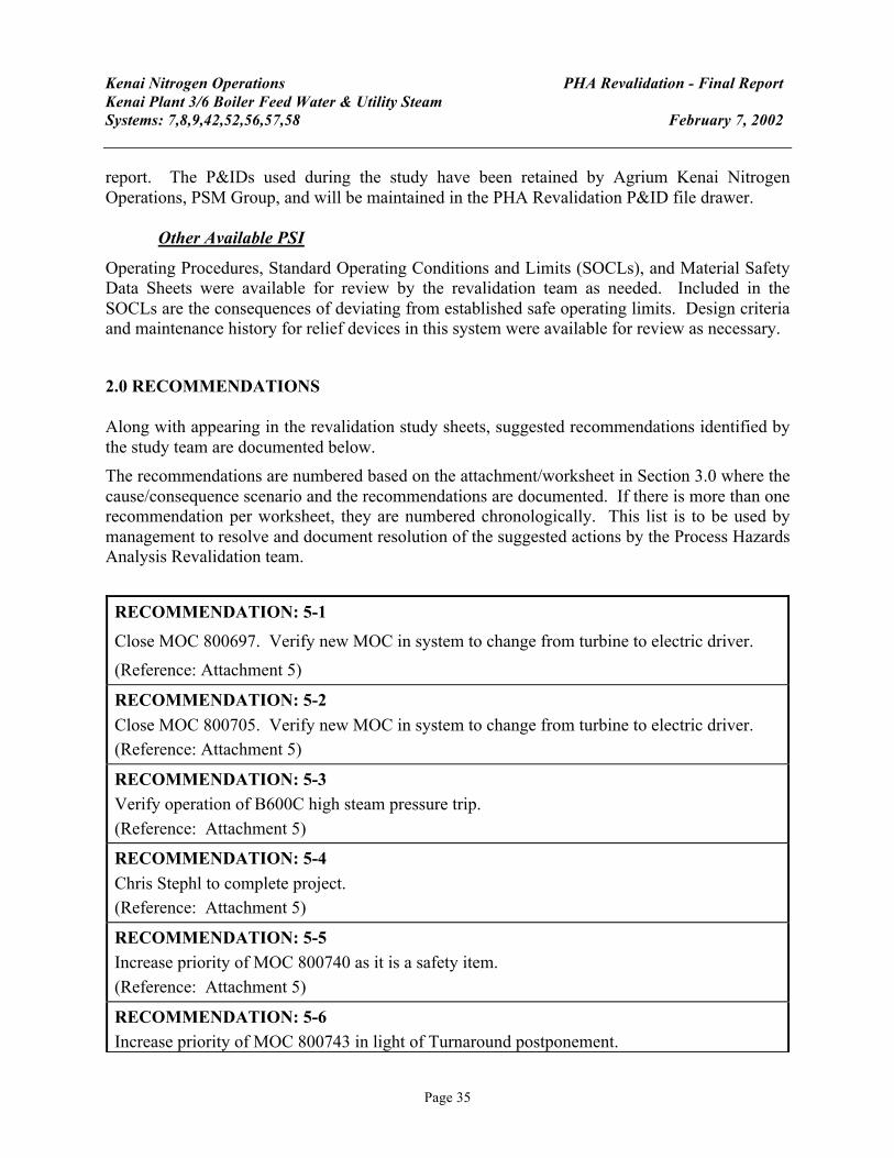
Kenai Nitrogen Operations PHA Revalidation - Final Report Kenai Plant 3/6 Boiler Feed Water & Utility Steam Systems: 7,8,9,42,52,56,57,58 February 7, 2002
Page 35
report. The P&IDs used during the study have been retained by Agrium Kenai Nitrogen Operations, PSM Group, and will be maintained in the PHA Revalidation P&ID file drawer.
Other Available PSI
Operating Procedures, Standard Operating Conditions and Limits (SOCLs), and Material Safety Data Sheets were available for review by the revalidation team as needed. Included in the SOCLs are the consequences of deviating from established safe operating limits. Design criteria and maintenance history for relief devices in this system were available for review as necessary.
2.0 RECOMMENDATIONS Along with appearing in the revalidation study sheets, suggested recommendations identified by the study team are documented below. The recommendations are numbered based on the attachment/worksheet in Section 3.0 where the cause/consequence scenario and the recommendations are documented. If there is more than one recommendation per worksheet, they are numbered chronologically. This list is to be used by management to resolve and document resolution of the suggested actions by the Process Hazards Analysis Revalidation team.
RECOMMENDATION: 5-1 Close MOC 800697. Verify new MOC in system to change from turbine to electric driver. (Reference: Attachment 5)
RECOMMENDATION: 5-2 Close MOC 800705. Verify new MOC in system to change from turbine to electric driver. (Reference: Attachment 5)
RECOMMENDATION: 5-3 Verify operation of B600C high steam pressure trip. (Reference: Attachment 5)
RECOMMENDATION: 5-4 Chris Stephl to complete project. (Reference: Attachment 5)
RECOMMENDATION: 5-5 Increase priority of MOC 800740 as it is a safety item. (Reference: Attachment 5)
RECOMMENDATION: 5-6 Increase priority of MOC 800743 in light of Turnaround postponement.

Kenai Nitrogen Operations PHA Revalidation - Final Report Kenai Plant 3/6 Boiler Feed Water & Utility Steam Systems: 7,8,9,42,52,56,57,58 February 7, 2002
Page 36
(Reference: Attachment 5)
RECOMMENDATION: 6-1 Develop and implement Loss of Cooling Water SOP(s) for Plants 3/6. (Reference: Attachment 6)
RECOMMENDATION: 8-1 Evaluate latest version of API RP 520 to determine if new standard impacts previously calculated relief valve sizing information.
(Reference: Attachment 8)
RECOMMENDATION: 9-1 Install 3rd demin pump and intertie for Plant 1.
(Reference: Attachment 9)
RECOMMENDATION: 11-1 AP-10 needs revised to reflect current usage of Taproot and Incidenter. Revisions may also be needed due to Agrium EHS policy. (Reference: Attachment 11)
RECOMMENDATION: 13-1 Install platform for safe access to 550 south/south and north/north interties. (Reference: Attachment 13)
RECOMMENDATION: 13-2 Install platform for safe access to Plant 4 jumpover from 1500# boiler feed water to low pressure boiler feed water header. (Reference: Attachment 13)
RECOMMENDATION: 13-3 Reroute tailpipe on PSV8112 so that it is not directly over Plant 4 high to low pressure boiler feed water intertie. (Reference: Attachment 13)
RECOMMENDATION: 13-4 Install PCV for high pressure boiler feed water to low pressure boiler feed water. (Reference: Attachment 13)
RECOMMENDATION: 13-5 Fabricate and install guard for HRSG/BMS shutdown switch in field Plant 3/6. (Reference: Attachment 13)
RECOMMENDATION: 13-6 Perform lighting survey in Plant 4 after replacement of all burned out lighting.

Kenai Nitrogen Operations PHA Revalidation - Final Report Kenai Plant 3/6 Boiler Feed Water & Utility Steam Systems: 7,8,9,42,52,56,57,58 February 7, 2002
Page 37
(Reference: Attachment 13)
RECOMMENDATION: 13-7 Replace old and worn out labels in Plant 4 Control Room. (Reference: Attachment 13)
RECOMMENDATION: 13-8 Fabricate and install guard for HRSG/BMS shutdown switch in Plant 3/6 Control Room. (Reference: Attachment 13)
RECOMMENDATION: 13-9 Identify valving that is not properly labeled and properly label it. Plant 3/6 (Reference: Attachment 13)
RECOMMENDATION: 13-10 Identify missing valve position indicators and write work requests to get repaired. Plant 4 (Reference: Attachment 13)
RECOMMENDATION: 13-11 Maintain current staffing levels. Provide adequate training time prior to required sign off date. After sign off, provide adequate on-the-job training. (Reference: Attachment 13)
RECOMMENDATION: 14-1 Management Review Team to consider making this a mandatory item for the 2003 budget due to the severe consequences of loss of demin water. (Reference: Attachment 14)
RECOMMENDATION: 14-2 Confirm proper loop operation after changeover to Foxboro DCS. (Suggested assignment to Keith Chilson) Completion contingent on budget approvals. (Reference: Attachment 14)
RECOMMENDATION: 14-3 Incident 23906 MUST be investigated. (Reference: Attachment 14)
RECOMMENDATION: 14-4 Add checkbox on confined space entry permit which refers to chemicals used in confined spaces or for vessel cleaning. Have there been chemicals used in the confined space prior to entry? Will you be using any chemicals while in confined space? (Reference: Attachment 14)

Kenai Nitrogen Operations PHA Revalidation - Final Report Kenai Plant 3/6 Boiler Feed Water & Utility Steam Systems: 7,8,9,42,52,56,57,58 February 7, 2002
Page 38
3.0 STUDY WORKSHEETS & ATTACHMENTS The following attachments were used throughout the PHA Revalidation and may be found on the following pages: Attachment 1 Revalidation Agenda Attachment 2 Initial PHA Content Checklist Attachment 3 Baseline PHA Screening Checklist Attachment 4 Discussion of Recommendations from Baseline PHA Attachment 5 Change Evaluation Checklist to Identify Undocumented Changes Attachment 6 Operations Change Evaluation and Wrap-up Checklist Attachment 7 Maintenance Change Evaluation and Wrap-up Checklist Attachment 8 Engineering Change Evaluation and Wrap-up Checklist Attachment 9 Inspection Change Evaluation and Wrap-up Checklist Attachment 10 Emergency Response Change Evaluation and Wrap-up Checklist Attachment 11 Safety Group Change Evaluation and Wrap-up Checklist Attachment 12 General Change Evaluation and Wrap-up Checklist Attachment 13 Human Factors Issues/Checklist Attachment 14 Previous Incident Reports Checklist Attachment 15 Evaluate Potential Off-Site Consequences Worksheet Attachment 16 Additional Areas "What-If" Worksheets Attachment 17 Revalidation Guideword Checklist Attachment 18 Risk Ranking Matrix