Plant Design and Commissioning - · PDF filePlant Design and Commissioning G.G. Stanley ......
63
Chapter 16 Plant Design and Commissioning G.G. Stanley 16.1 The Importance of Good Plant Design and Punctual Commissioning Two very important aspects of extraction metallurgy for which the metallurgical engineer is responsible are plant design and plant commission- ing. Their importance arises from the fact that both are closely related to the financial success of the overall project of which they form part. In the long term, good design is imperative if the profit on the capital invested in the plant, and indeed in the whole undertaking of which the plant is part, is to be maximized. Furthermore, good design can itself contribute greatly to easing commissioning problems, and together with a carefully-planned and executed start-up can make possible the crowning success of a plant brought into production on time, at designed capacity and efficiency and within budget. When each day of lost production can cost thousands of Rands, commissioning delays can become extremely costly. 16.2 The Design and Construction Organization Before a plant of any significance can be designed and built, an organiza- tion for carrying out these tasks must be set up. Several types of organiza- tion are possible, and some of these are: (1) Design and construction done entirely 'in-house', i.e. entirely by the owner company w!th its own design and construction resources. In South African practice where the vast majority of mines are founded by one or other of the mining groups, the term' owner company' would include the founding group. (2) Design and construction done entirely on contract by an outside firm on a 'turn-key' basis, i.e. the plant is handed over to the owner as a going concern on completion of commissioning. (3) Design done by the owner company and construction by outside con- tractors. This is the system most frequently used for South African gold plants. (4) A joint owner-contractor design and administration organization where both parties supply personnel and resources on an agreed basis, but construction is usually done by the contractor or a sub-contractor. There are several other possibilities, and the owner company will choose whichever best suits its circumstances. Where an outside contractor is involved 907
Transcript of Plant Design and Commissioning - · PDF filePlant Design and Commissioning G.G. Stanley ......

Chapter 16
Plant Design and Commissioning
G.G. Stanley
16.1 The Importance of Good Plant Design and Punctual Commissioning Two very important aspects of extraction metallurgy for which the metallurgical engineer is responsible are plant design and plant commissioning. Their importance arises from the fact that both are closely related to the financial success of the overall project of which they form part. In the long term, good design is imperative if the profit on the capital invested in the plant, and indeed in the whole undertaking of which the plant is part, is to be maximized. Furthermore, good design can itself contribute greatly to easing commissioning problems, and together with a carefully-planned and executed start-up can make possible the crowning success of a plant brought into production on time, at designed capacity and efficiency and within budget. When each day of lost production can cost thousands of Rands, commissioning delays can become extremely costly.
16.2 The Design and Construction Organization Before a plant of any significance can be designed and built, an organization for carrying out these tasks must be set up. Several types of organization are possible, and some of these are:
(1) Design and construction done entirely 'in-house', i.e. entirely by the owner company w!th its own design and construction resources. In South African practice where the vast majority of mines are founded by one or other of the mining groups, the term' owner company' would include the founding group.
(2) Design and construction done entirely on contract by an outside firm on a 'turn-key' basis, i.e. the plant is handed over to the owner as a going concern on completion of commissioning.
(3) Design done by the owner company and construction by outside contractors. This is the system most frequently used for South African gold plants.
(4) A joint owner-contractor design and administration organization where both parties supply personnel and resources on an agreed basis, but construction is usually done by the contractor or a sub-contractor.
There are several other possibilities, and the owner company will choose whichever best suits its circumstances. Where an outside contractor is involved
907

THE EXTRACTIVE METALLURGY OF GOLD
as a prime contractor on design and/or construction, it is highly desirable that such contractor be thoroughly familiar with local conditions, and preferably be able to demonstrate the successful execution of several local contracts.
16.3 Status, Responsibilities ami Qualities of the Design Metallurgist Regardless of the type of organization chosen, it is absolutely essential to success that a metallurgical engineer be included in the Project Team and that in matters affecting metallurgical design, the metallurgist's decision shall be supreme. All other disciplines must accept that in this instance they are there to serve the metallurgist's purpose and that the metallurgist is not simply there to act as an adviser to them; his requirements must be paramount, even though, as is likely, he will not be in command of the design and construction organization. The metallurgist carries the responsibility for the technical success of the project, and consequently must insist that he shall have the ultimate say regarding metallurgical matters. This, of course, is not to say that the metallurgist is to be totally inflexible in his attitude. All engineering is a compromise, and it is the metallurgist's obligation to keep an open mind, to ensure that whatever compromise has to be made is the best possible one from the metallurgical viewpoint, and with imagination, even to seize some benefit from it. The metallurgist assigned to a design team must also realize that the achievement of a successful design is probably more dependent on him than any other member of the team; it requires of him much hard work, meticulous attention to detail at all stages, experience, imagination, determination, the ability to communicate, and above all, a profound knowledge of the technical and operating aspects of the subject. Armed with these qualities, he will have the authority to ensure that the metallurgical aspects of the plant design will receive the priority they must have if success is to be achieved.
16.4 General Procedure for Plant Design 16.4.1 The procedural plan The efficient execution of all design and construction projects requires a proper plan of procedure, that is, the setting-up at the initiation of the project, of a list of the steps that must be completed, arranged in the sequence in which they must occur for the project to proceed in a logical and orderly fashion. Such a plan, in the case of an ore-treatment plant, could be as follows:
(1) Ore testing (2) Process definition (3) Production of basic flowsheets (4) Production of piping and instrumentation diagrams (5) Production of general arrangement drawings and conceptual models (6) Equipment selection and specification (7) Costing and preparation of definitive budget
908

PLANT DESIGN AND COMMISSIONING
(8) Production of final flowsheets (9) Production of detailed design drawings and models
(10) Construction (11) Commissioning
The steps in the plan frequently overlap, and furthermore, there are many other activities involved in the creation of an operating plant, but those listed are the ones normally involving the metallurgical engineer, and these will be dealt with in the following discussion.
16.4.2 Ore testing The first step in designing a successful ore-treatment plant is to obtain the most comprehensive information possible regarding the ore to be treated. The more comprehensive the information, the less will be the likelihood of unpleasant surprises regarding the nature of the ore after the plant has been commissioned, surprises which can be extremely inconvenient and costly to deal with once the plant has been built. In other words, the more and better the information, the more likely will it be that the design will be 'right the first time'. The relatively small cost of obtaining the maximum possible information regarding the ore before plant design commences is usually money well spent, and should not be begrudged.
Generally speaking, the object of testing Witwatersrand and Free State gold ores is simply to check their amenability to the known processes of gold recovery such as comminution, concentration, thickening, cyanidation at ambient pressure and temperature, liquid! solid separation, and recovery of gold from solution; and to obtain design data for the application of these processes. In other words, known processes are capable of yielding acceptable recoveries so that process development is not necessary. The same remarks apply in general to the Barberton sulphide ores, which although more refractory than Witwatersrand and Free State ores, can usually be made to give acceptable yields by suitable application of known techniques. The subject of Process Development is therefore not dealt with in this book, although it is conceivable that some South African gold deposit will yet require the development of completely new techniques to enable profitable recovery of its gold.
16.4.2.1 Obtaining the sample Orebody samples At this stage of the exploitation of the Witwatersrand conglomerate reefs, practically any new area developed is likely to be covered by at least a thousand metres of younger rocks. Thus, unless the area is rapidly accessible to already-existing development, the first bulk sample of ore available is that obtained from a shaft intersection. But the time necessary for the design and construction of a large new plant can be five years or more, and the amount of capital tied up in shaft-sinking and development for a new Witwatersrand mine is enormous. This capital cannot become productive until the plant is commissioned. Consequently plant design cannot await exposure of the orebody in shafts or other development. Thus the only samples normally
909

THE EXTRACTIVE METALLURGY OF GOLD
available when a new Witwatersrand plant is designed are a very limited number of borehole cores.
In the case of South African gold deposits outside the WitwatersrandFree State conglomerate system, the mining depths involved are very much less and the scale of operations is normally far smaller. Consequently the amounts of money involved are vastly less. There is tpus a greater possibility in the case of these non-Witwatersrand deposits that plant design can be delayed until good orebody exposures have been obtained in underground development. But even in the case of non-Witwatersrand deposits, it frequently is the case that the plant must be designed on the basis of borehole cores only.
The amount of sample contained in a single borehole core is of course very limited, and it should be standard practice to drill several deflections from the original hole whenever values are intersected.
Regardless of the source of the initial samples, it is highly unlikely that they will be fully representative of the ore body. The design metallurgist must attempt to compensate for this by drawing on all available information regarding deposits as close as possible in nature and location to the one he is concerned with, and also by allowing sufficient latitude in his design to accommodate any likely variations in ore characteristics. In this regard, Wit watersrand metallurgists are fortunate in having to deal with a deposit which is almost unique in the consistency of its properties over several hundred kilometres, and about whose characteristics so much is already known.
Sampling surface dumps and dams In contrast to unmined ore, surface dumps and dams are usually reasonably easily accessible. They do however, present considerable sampling difficulties of their own, and special techniques have to be employed for each type of dump.
Rock dumps can be sampled from shafts sunk through them, adits driven into them or channels cut through them, any of which techniques really calls for mining expertise. However, the problem of the accurate sampling of coarse rock produced by these primary operations is well-known, and involves a large-scale splitting operation ranging from automatic sampling to selection of a certain proportion of loaded conveyances. Failing such splitting, the whole primary sample must be submitted to a pilot-scale plant operation designed to produce the required design information. Care should be taken when obtaining the primary sample from a surface rock dump containing a mixture of fine and coarse material (i.e. almost any dump containing material that has not previously been washed), to avoid inaccuracy due to the downward migration of the fines resulting from the percolation of rain water. Dense constituents of the dump, particularly gold and uranium minerals, can be carried to considerable depths into the underlying soil.
Interest in sampling sand dumps, usually old tailings dumps, has increased of recent years with the rising gold price, while sampling of slimes residue dams has frequently been undertaken in connection with the uranium and pyrite recovery programmes in South Africa, and for obtaining stability data;
910

PLANT DESIGN AND COMMISSIONING
(see Chapter 12). The method usually adopted in all these cases is auger sampling, the resulting hole being lined with piping of suitable diameter to prevent collapse of the hole and contamination of the sample with wall material. For holes of any appreciable depth, some form of lifting tackle has to be provided for removal of the charged auger from the hole.
16.4.2.2 Mineralogical examination Mineralogical examination is normally carried out by a specialist mineralogist, and in the case of ore samples is done on polished sections of the rock. Techniques used include optical microscopy, electron microscopy, microprobe analysis and gangue dissolution (Lamos, 1982). The object of mineralogical examination is twofold: first to establish the composition of the rock, the mineral species present and their proportions, and second to determine the association of the gold, that is, the proportions that are 'free', that are locked within other minerals, particularly sulphides, and the size and range of the gold particles. Knowledge of the mineralogy identifies minerals which might cause difficulties in metallurgical treatment, and can also reveal the presence of minerals of potential economic value in addition to the gold, silver, sulphur and uranium for which samples are normally assayed. (For example, nickel and cobalt are known to occur in the Witwatersrand conglomerates and could become of economic significance in future.) Minerals which can cause difficulties in gold-silver extraction are those which adversely affect the cyanidation process, those which adversely affect other phases of the treatment process such as grinding, concentration, thickening or filtration, and those which can cause environmental problems. In the first category are sulphides and minerals containing arsenic, antimony or copper (see Chapter 15) and carbon, while in the second are very hard minerals which could cause crushing and grinding difficulties, clay minerals and phyllosilicates which can cause transport, thickening and filtration problems and also gold adsorption problems from cyanide solution, and finally, in the third category, mercury and its minerals.
Mineralogical methods can examine individual pieces of rock only. Hence it is important that a large number of pieces, as representative as possible of the likely feed to a treatment plant, should be examined in order to avoid any bias in the overall picture. Because of the fact that gold normally occurs in extremely low concentrations, it is very difficult to derive any useful information about it by' mineralogical examination of polished sections. (In South African gold ores, silver occurs as a solid solution in the gold and hence is seldom reported on although present to the extent of 100/0 or more of the gold.) However, mineralogical investigation of a new ore should include examination of a concentrate of the heavy constituents (most easily obtained by heavy medium separation of a milled ore sample using bromoform as the medium); this can give some information regarding the nature of the gold and uranium mineralization, particularly with regard to particle size and surface condition and the extent of locking within other minerals, all of which can be extremely useful from the plant design viewpoint.
911

THE EXTRACTIVE METALLURGY OF GOLD
16.4.2.3 Sample preparation The primary sample The type of preparation necessary depends on the type of sample available and the testing to be done. In the case of borehole cores, preparation before crushing can consist of little less than selection of appropriate lengths of the core to include the correct proportions of reef and waste, followed possibly by grouping of the cores into combinations representative of specific areas of the orebody if it is suspected that the ore properties may vary from area to area. After crushing and mixing, actual metallurgical testing can commence, although the extent of the testing possible on such a limited sample as borehole cores is obviously restricted. Priority should be given to batch cyanidation tests as these give a good overall picture of the amenability of the ore to treatment; thereafter, depending on the amount of sample available, testing can be progressively extended to other aspects of treatment. But it must be borne in mind that even a single rolling bottle cyanidation test will require several kilograms of sample, allowing for the necessary quantities for assay, if any reasonable accuracy is to be achieved.
Bulk samples permit much more scope in metallurgical testing than borehole cores. The necessity for splitting or 'sampling the sample' if the original bulk sample is too large, has already been mentioned in Section 16.4.2.1; accurate splitting of run-of-mine samples is always difficult, and should be avoided, if possible, until at least primary crushing has been performed.
Methods for splitting or sampling coarse materials include:
(1) Use of an automatic sampling plant specially designed for handling runof-mine feeds. This can be single- or multi-stage, depending on the extent of reduction and the accuracy required.
(2) Conveying the material in a large number of small batches, as in frontend loader scoops or railway trucks, and the selection and separate dumping of a certain proportion of the batches to form the sample.
(3) Forming the primary sample into a homogeneous bed by depositing it in successive layers, one above the other, in an elongated heap, and then removing a transverse slice from the heap to form the sample.
(4) Splitting the material into size fractions, determining the relative proportions of the fractions and then recombining some of each of the fractions in the correct proportions to form the sample. This method obviously yields the size distribution of the original sample, which is invaluable where it represents the feed to a crusher station or to a runof-mine milling operation.
Other methods of splitting coarse bulk samples can no doubt be devised, but these examples indicate the sort of operation involved. In all cases, great care must be taken to avoid loss of fines, since the fines are normally enriched by already-released valuable components; where the possibility of dusting losses exists, it may be advisable to dampen the sample slightly.
The relationship between sample size and accuracy is discussed in Chapter 13.
912

PLANT DESIGN AND COMMISSIONING
At this stage, unless run-of-mine milling tests or possibly sorting tests are to be done, size reduction of the selected portion of the primary sample can commence. This is usually done by means of pilot-scale jaw crushers or some other type of crusher capable of handling wet fines, if no washing of the sample has yet been done. Where a considerable degree of size reduction (say greater than 4: 1) is required, successive passes through a progressively more tightly adjusted crusher may be necessary. The opportunity should not be missed of collecting data on crushing energy requirements, although this will require the measurement of both ore mass and crusher energy input.
Primary crushing can bring the maximum particle size into the 25 to 30 mm range, at which size mixing and splitting are considerably easier than on run-of-mine material. Suitable splitting methods at this stage include: (1) coning and quartering, (2) riffling, and (3) use of single- or multi-stage mechanical splitting plants, and various others.
The secondary sample Splitting of the primary sample as just described yields a secondary sample which will normally be the source of material for actual metallurgical testing. The size of the secondary sample will depend on whether the subsequent testing is to be at laboratory or pilot plant scale; if the former, the secondary sample can be of the order of 100 kg, while for pilot plant testing, anything up to 100 t or more could be required. In the case of pilot-scale testing, crushing of the primary sample can be done on a continuous basis and form part of the actual testing.
16.4.2.4 Laboratory testing Metallurgical testing of gold ore that can be carried out at laboratory scale includes:
(a) Gold, silver, sulphur and uranium assays. (b) Conventional grindability determination. (c) Pebble competence testing and autogenous grindability determination. (d) Thickening. (e) Cyanidation, including reagent consumption and effects of fineness of
grind and contact time. (t) Filtration. (g) Concentration by gravity methods and flotation.
(a) Assaying Gold, silver, sulphur and uranium assays should be done as a mat
ter of routine on new Witwatersrand ore head samples. For Barberton area ores, arsenic and antimony assays should be included. Silver can usually be omitted once the head gold: silver ratio has been determined. Uranium can be omitted when gold-only treatment is envisaged, although its behaviour in any concentrating operation for other constituents should be checked on. 0,5 kg of sample is sufficient for a head assay and 1,0 kg for a residue assay, both in triplicate.
913

THE EXTRACTIVE METALLURGY OF GOLD
(b) Conventional grindability determination The determination of grindability (i.e. the energy necessary per unit
mass to produce a given size reduction) in rod, ball and pebble milling at laboratory scale is usually done by the Bond method, which produces the Bond Grindability Index for the sample. The method is well described by Pownall (1962), who also describes the use of the result in mill size selection, a subject that is more fully dealt with in Appendix 3.4 of Chapter 3.
25 kg of sample is required for determination of the Bond Index at several different mesh sizes with some check determinations if necessary.
In connection with grindability testing, it should be borne in mind that batch laboratory tests do not produce the same size distributions, particularly of minerals and metals, as does continuous plant grinding. Continuous pilot plant testing is perhaps the answer here.
(c) Pebble competence testing and autogenous grindability determination The suitability of an ore for autogenous milling is partly deter
mined by the competence of the large sizes to form grinding media, i.e. their ability to experience the forces in a tumbling mill with a low probability of shattering. Three methods of testing this characteristic have been employed, namely simple dropping of representative pieces onto a hard surface, tumbling a sample of the large pieces in a rotating drum, and pendulum crushing of sample pieces. Apparently only the first of these methods has been used in South Africa; it results in a 'number of drops versus per cent remaining mass' curve (Figure 16.1), which is compared with the curve for an ore of known milling characteristics.
Autogenous grindability is measured at batch scale by the use of a simulated closed circuit test, similar to the Bond grindability test. Both pebble competence and autogenous grindability tests are discussed further in Appendix 3.3 of Chapter 3.
(d) Thickening Thickening tests are usually done by measuring the settlement rate,
i. e. the rate of fall of the slime/clear water interface of the pulp in a transparent measuring cylinder. The method of performing the test and of using the information obtained for the calculation of thickener capacity is given in an appendix to Chapter 18 (Appendix 18.3). Papers by Moncrieff (1963), Barnea (1977) and Wildhelm and Naida (1979) deal with the subject. Thickening tests can be done on the products from grindability testing, so should require no additional quantities of original sample.
(e) Cyanidation
914
Since, in the case of Witwatersrand-type ores, cyanidation alone is normally capable of dissolving well in excess of 900/0 of the gold, cyanidation is the most significant test of the ore's amenability to treatment that can be made. Barberton ores, however, usually require some form of pretreatment to render the locked gold accessible to cyanide

PLANT DESIGN AND COMMISSIONING
100~----~----~------~----~-----T
Of)
" ·2 80 .@
a ~ on on
'" a <il " 60 .51> ·c o
4-< o <I)
~ [J 40
~
Number of drops 10 20 30 40 50 Illo Mass remaining 57,5 47,0 37,1 31,3 26,1
Drop height = 2,74 m
o
20+------,-----,------.-----,------+ o 10 20 30 40 50
Number of drops
Figure 16.1. Number of drops versus per cent remaining mass for Leslie ore.
and to eliminate arsenic and antimony, but thereafter cyanidation is usually capable of making a significant extraction of gold, so that again, the cyanidation test is of crucial significance.
Cyanidation testing at laboratory scale is normally done by the rolling-bottle method. Where no pretreatment is required, testing can be done directly on the product of gIindability determination, although if a fineness of grind versus extraction relationship is to be obtained, a number of grinds in addition to those for grindability testing will be required. If at all possible tests should also be done for different contact times to determine a contact-time versus extraction relationship since this is very important information for plant design. The cyanidation test can also give useful information regarding cyanide and lime consumption. Assuming that lO-litre bottles are used about half full at pulp density of 1,46 (i. e. 1: 1 liquid: solid), about 3,6 kg of solids will be required for each bottle charge. If 4 grinds at a standard treatment time of 30 hours are tested together with 3 other treatment times in the range 25 to 40 hours at say 80 070 -75 j.tm, a total of 7 tests will be done. These should be duplicated, so that the quantity of sample required for reasonably comprehensive testing will be 14 x 3,6 = 50,4 kg.
Refer to Chapter 18, Appendix 18.5, for details of the cyanidation test.
(t) Filtration Testing for filtrability can, and should, be done on the products
915
THE EXTRACTIVE METALLURGY OF GOLD
from the various cyanidation tests. The tests usually comprise measurement of the rate of the removal of filtrate from a feed slurry by batch vacuum filtration under standard conditions in a Buchner funnel, or using a specially constructed miniature filter leaf submerged in the pulp sample. Refer to Chapter 18, Appendix 18.4, for details of filtration testing. Methods of using the results in the calculation of filter duty are given by Osborne (1975) and Dahlstrom and Purchas (1957). The tests should also include a determination of the dissolved gold losses to be expected at various applied wash ratios (i.e. ratio of applied wash to solids filtered) above and below about 1: 1 by mass.
(g) Concentration
916
Because of their cheapness, the preferred plant-scale methods of concentrating gold and other dense constituents of South African ores are gravity methods .. However, it is difficult to simulate gravity concentration satisfactorily in batch-wise bench-scale operation with the type of equipment used in full-scale plants, such as J ohnson drums, continuous riffle belt concentrators and strakes such as plane tables. But laboratory equipment specifically designed for this purpose, e.g. the Haultain Superpanner and the micropanner, and even bench-scale batch heavy medium separation using bromoform (r.d. = 2,83) diluted as required with xylene (r.d. = 0,86) or carbon tetrachloride (r.d. = 1,59), can give some indication of the concentrate quantities and grades to be expected at various grinds. 2 kg of sample should be sufficient for these tests.
Flotation is used in some Witwatersrand and Free State gold plants for concentrating sulphides for the production of sulphuric acid and with the secondary aim of enabling further intensive treatment of the sulphides for the recovery of locked gold (see Chapter 5). In the case of Barberton-type sulphide ores, a gold-sulphide concentrate is made which is roasted to render the gold-enclosing sulphides porous and to eliminate arsenic and antimony to enable successful recovery of the gold by cyanidation (see Chapter 8). Where cyanidation tests have given poor recoveries owing to a high proportion of gold locked in pyrite or because of the presence of arsenic or antimony, flotation tests should be included in the laboratory testing. These will indicate the recoveries of sulphides and gold that can be expected by this method, and may yield some information about required flotation contact times and reagent consumptions. If sufficient concentrate can be made, information about its subsequent treatment for recovery of the gold can be obtained. 10 kg of sample will be sufficient for flotation tests alone, but anything up to 100 kg, will be required if adequate concentrate is to be made for exploratory work on concentrate treatment.
The performance of all the laboratory tests indicated in Section 16.4.2.4 will require something approaching 6 tons of sample (200 kg if the pebble competence and autogenous grindability tests are excluded), but will yield a picture of the ore's treatment requirements which in most cases will be entirely adequate for the design of a successful

PLANT DESIGN AND COMMISSIONING
Table 16.1. The quantities of sample required for the performance of the various types of la bora tory test.
Type of test
Head assay (triplicate) Residue assay (triplicate) Ball, pebble or rod mill grindability (Bond test) Cyanidation Heavy medium concentration Flotation Concentrate roasting Pebble competence and autogenous grindability
Sample mass required (kg)
0,5 1,0 25 50 2
10 100
6000
flowsheet. Table 16.1 summarizes the quantities of sample required for the various tests.
16.4.2.5 Pilot plant testing Generally, laboratory scale testing, together with data from existing plants, will yield all the data necessary for the design of plants to treat non-refractory ores such as the Witwatersrand and Free State conglomerates. However, in the case of relatively unknown and refractory ores, it may be advisable to include pilot-scale testing as well. Pilot testing and the reasons which could make it advisable are discussed in Chapter 18. It must, however, be borne in mind that pilot plant testing is expensive and should not be done unnecessarily.
16.4.3 Process Design 16.4.3.1 Process Design Criteria The design process proper commences with the drawing up of the Process Design Criteria. This is essentially a statement of what the plant will be required to do and the framework within which it will have to do it. It includes a statement of the capacity the plant is to have, what material it is to treat, the sources of its feed, what it is to produce, the time schedule for the commissioning of the various stages and general information regarding the externally imposed parameters of the plant design. It is normally prepared by the mining and financial consultants of the company that will own the plant. It deals essentially with what the plant is to achieve, and as such is the basic directive to the plant designers, setting the limits within which they must operate, and the targets they must attain. The design metallurgist must insist that he be given the Process Design Criteria as part of the essential documentation of his commission.
16.4.3.2 Flowsheet design Whereas the Process Design Criteria lay down what is to be achieved by the plant, the flowsheet has to do with the means by which the objectives are
917
THE EXTRACTIVE METALLURGY OF GOLD
to be attained. It is a diagrammatic definition of how the requirements specified in the design criteria are to be achieved, and its preparation is essentially the business of the metallurgical engineer. Flowsheet design is a major and vital part of the design process, and the correct choice of flowsheet is crucial to the technical and financial success of the plant to be built.
The design process Flowsheet design is the arranging in diagrammatic form of the necessary
equipment, installations and interconnections to achieve the goals specified in the design criteria, while complying with the treatment requirements indicated by test work or any other source of information. Initial flowsheet design usually takes the form of a drawing-up of very rough freehand blocktype conceptual diagrams based on the design metallurgist's knowledge of the subject. These preliminary diagrams are subjected to a process of consideration, discussion, analysis and development by the designer and his associates, and as a result gradually evolve to a stage where they can either be rejected or handed over to a draftsman for drawing up in a more standardized format. It is usually the case that several technically feasible treatment routes will emerge from this initial design activity. Almost invariably, an estimate of the capital cost of the proposed plant will be required at an early stage of the project, particularly if a decision has to be made among several possible alternatives. Accordingly the aim of this first stage must be to produce a flowsheet of each possible treatment route in sufficient detail to permit the preparation of a capital cost estimate. However, great detail is to be avoided, since generally all that is required at this stage is an Order of Magnitude estimate as quickly as possible. This estimate is based on rough prices for the major equipment in each plant area (e.g. the mills), increased by rule-of-thumb factors to cover the ancillary equipment and buildings. For example, the cost of a complete milling unit including foundations, ore storage, conveyors, sumps, pipes, buildings, etc. is approximately five times that of the mill and drive itself. Another useful rule-of-thumb is that the capital cost of gold extraction plants varies as (capacity)'iJ, while Ruhmer, Svoboda and Wilson (1984) give relationships between price and capacity of individual types of machine. Greater detailing and progressively more accurate costing are called for as the project proceeds and the design becomes increasingly more defined, passing from the Order of Magnitude estimate to the Preliminary Estimate (- 15 % + 25 %) to the Definitive Estimate (-10% + 10%) and finally the Detailed or Revised Estimate (- 5% + 5%).
16.4.3.3 Quantified flowsheet For a flowsheet to be of use in subsequent costing, evaluation and design stages, it must be quantified, i.e. include the necessary information regarding the flow streams throughout the plant, and the equipment to be installed in the plant. The preparation of a quantified flowsheet is greatly facilitated by the use of a standardized form of drawing sheet, the AO being a convenient size, on which are printed tabulations for the entering of flow (or stream) data and of equipment data. The flow data table is printed at the bottom
91R

PLANT DESIGN AND COMMISSIONING
Table 16.2. Example of a flow data table.
Water: Stream Descrip- Solids Water Pulp % solid Other
No. tion (t/h) (t/h) (t/h) Solids r.d. ratio m1/h m'/min data
2 3
etc.
of the sheet, and may be headed as shown in Table 16.2. This tabulation can be repeated across the whole width of the sheet, ex
cept for the title space in the right-hand corner; it can occupy 10 to 20070 of the top-to-bottom dimension of the sheet.
A flowsheet of any appreciable size will probably have to be divided into sections that can conveniently be accommodated on the printed sheets described, so that in fact 'the flowsheet' will become a set of flowsheets. A section of the overall flowsheet is then drawn on each sheet of the set in the appropriate detail, using stylized representations of the various pieces of equipment and lines of different types for the interconnecting flows, e.g. solid lines for ore and pulp, dotted for water, chain dotted for compressed air, and so on.
In the case of duplicated streams, it is necessary to show only one stream on the flowsheet, provided it is made clear under the heading 'Description' of the flow data table that the stream shown is 'one of X', X being the number of parallel streams; the quantities under the other headings will then be for one stream only.
Each stream in the flowsheet is numbered and entry of data into the flow data table commences with the insertion of a description and all available primary data for each stream against its number in the table. Primary data are those data available at this stage; they are the data on which the flowsheet design to this stage has been based, and are usually obtained from the des~gn criteria and test results.
Initially, all flow rates must be either monthly flow rates or must be based on the full number of time units in the length of month specified in the design criteria, taking no account of the fact that for various reasons actual running times will be less than 100% of calendar time. They should be pencilled in at this stage. These initial flow rates are subsequently corrected to actual flow rates when the actual running time for each section of the plant has been estimated as explained in the section 'Estimating Running Times' further on in this chapter.
When all primary data have been entered, the secondary, or derived, data are next calculated or estimated and inserted in the tabulation. The secondary data are frequently derived from flow balancing around sections of the flowsheet, and an example of this follows.
919

THE EXTRACTIVE METALLURGY OF GOLD
2 x 50 tlh W/S = 0,53
Inlet dilution ~
.~t~~~ ,,_ 'i'>\ljo~ ~A
50 t/h
150 tlh W/S = 1,2
Ball mill
B
Discharge dilution
D
Figure 16.2. Flow diagram with primary data.
Flow balancing Suppose we have that the new feed rate to a ball mill-classifier circuit is 50 dry tlh of crushed ore containing 8070 moisture, that the mill discharge w/s is to beO,42 and the cyclone under flow w/s is to beO,53. Experience has shown that with the size of cyclone to be used, the overflow w/ s will have to be about 1,20 to give the required overflow size distribution, and that a circulating load ratio of 2: 1 is to be expected. To complete the flow rate tabulation, we are required to calculate all the flows and associated data around the circuit, including dilution water flow rates. The method is firstly to draw a rough flow diagram with all the primary data entered on it (Figure 16.2),
Next draw up, on the bottom of the flowsheet, a flow rate table headed as in Table 16.2 and enter on it, in the sequence in which tliey appear on the rough flow diagram, all the flows into and around the circuit. The tabulation will then look like Table 16.3.
Then, in the tabulation,
920
A2 (Le. line A, column 2) = (100 x Al)/ A4 - Al 4,4 A3 Al + A2 = 54,4 A7 = A1I2,7 + A2 = 22,9 A8 = A7 x (1000/60) = A7 x 16,67 = 382 B5 (B6+1)/(B6 + 0,37) (by formula) = 1,7 B2 Bl x B6 = 53 B3 Bl + B2 = 153 B7 (BII2,7) + B2 = 90 D5 (D6 + 1)/(D6 + 0,37) (by formula) 1,8 D2 = Dl x D6 '7 63,0 D3 Dl + D2 = 213 D4 = (DlID3) x 100 = 70 D7 = (D1I2,7) + D2 = 118 D8 = D7 x 16,67 = 1974 C2 = D2 - (A2 + B2) =: 5,2 C7 C2 5,2 C8 = C7 x 16,67 = 86,7,
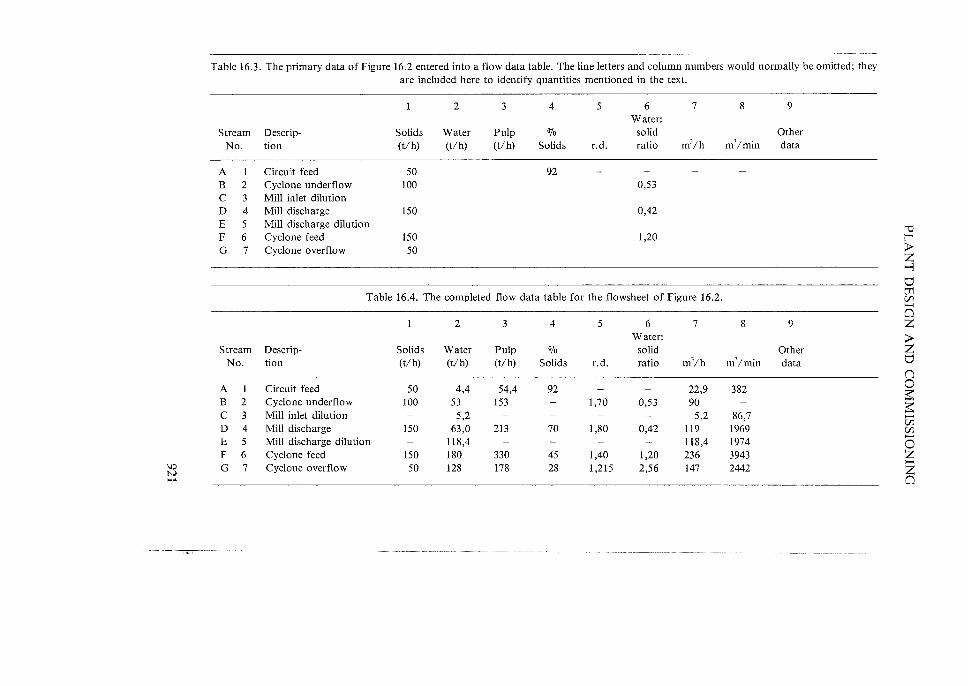
Table 16.3. The primary data of Figure 16.2 entered into a flow data table. The line letters and column numbers would normally be omitted; they are included here to identify quantities mentioned in the text.
2 3 4 5 6 7 8 9 Water:
Stream Descrip- Solids Water Pulp 070 solid Other No. tion (t/h) (t/h) (t/h) Solids r.d. ratio m3/h m3/min data
A Circuit feed 50 92 B 2 Cyclone underflow 100 0,53 C 3 Mill inlet dilution D 4 Mill discharge 150 0,42 E 5 Mill discharge dilution 'V F 6 Cyclone feed 150 1,20 l' G 7 Cyclone overflow 50 ;...
Z ..., ti
Table 16.4. The completed flow data table for the flowsheet of Figure 16.2. tJj (fJ ....... 0
2 3 4 5 6 7 8 9 Z Water: ;...
Stream Descrip- Solids Water Pulp % solid Other Z No. tion (t/h) (t/h) (t/h) Solids r.d. ratio m3/h m3/ min data ti
n A Circuit feed 50 4,4 54,4 92 22,9 382 0
$; B 2 Cyclone underflow 100 53 153 1,70 0,53 90 $; C 3 Mill inlet dilution 5,2 5,2 86,7 ....... D 4 Mill discharge 150 63,0 213 70 1,80 0,42 119 1969
(fJ (fJ
E 5 Mill discharge dilution 118,4 118,4 1974 ....... 0
F 6 Cyclone feed 150 180 330 45 1,40 1,20 236 3943 Z "0 G 7 Cyclone overflow 50 128 178 28 1,215 2,56 2442
>-< 1'-.) 147 Z .... ~ 0

THE EXTRACTIVE METALLURGY OF GOLD
and so on. The mill discharge dilution is calculated by difference between cyclone feed and the mill discharge, and finally cyclone overflow is the difference between cyclone feed and cyclone underflow. The calculations are obviously well suited for performance on a programmable calculator. The completed tabulation will be as shown in Table 16.4.
A 7 and A8 are included as they provide a useful check on the accuracy of the calculation, for the sum of all the flows entering the circuit should equal the only flow leaving it, i.e. A7 + C7 + E7 = G7 and likewise for the corresponding figures in column 8.
This example shows how a large amount of useful output data can be inferred from a small amount of input data in the case of a closed circuit. The final step would be to transcribe the data into the flow data tabulation on the flowsheet.
Estimating running times The flow rates initially entered in the flow data tabulations are based on 100070 running time. Before these can be corrected to actual flow rates, estimates of actual running times must be made.
The factors involved in estimating running times are:
(1) the scheduled running time in the section of the plant concerned, that is, the number of hours per month during which it will be manned and is planned to run,
(2) the proportion of lost time to be expected as the result of random unplanned stoppages such as breakdowns, power failures, chute blockages, etc., as well as of routine maintenance where this has to take place within scheduled running time as defined above.
Of major significance to the setting of scheduled running times are the provisions of the South African Mines and Works Act (Act 27 of 1956). Section 9(1)(c) of this Act states 'no person shall perform or cause or permit imy other person to perform, at any mine or works, any work in connection with the operation of a mine or works, on a Sunday, Christmas Day, Day of the Covenant or Good Friday, or cause any other person to perform, at any mine or works, any such work on Republic Day, unless the work is operating any continuous chemical, metallurgical or smelting process, if a stoppage thereof during the whole of any such day would either prevent its immediate resumption on the next succeeding day or diminish the effectiveness of the process.' The effect of this is that ore hoisting and operation of crusher plant may not take place, without special permission, on Sundays, Christmas Day, Day of the Covenant or Good Friday, but may take place on Republic Day, which is a non-compulsory working day. Milling and cyanidation, on the other hand, may be carried out on any and every day of the year. In addition to the limitations imposed by the Mines and Works Act, crusher station operation is frequently limited by company policy to less than three shjftsper day for reasons which include synchronization with ore hoisting schedules and reducing maximum demand on the electric power supply system. Thus whereas scheduled milling and cyanidation plant running times
922
PLANT DESIGN AND COMMISSIONING
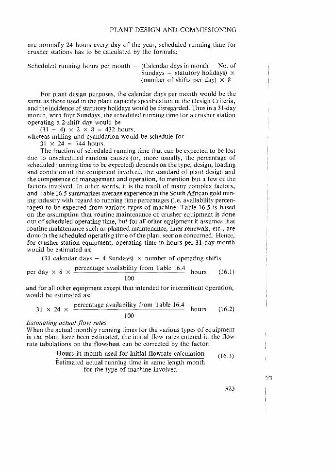
are normally 24 hours every day of the year, scheduled running time for crusher stations has to be calculated by the formula:
Scheduled running hours per month = (Calendar days in month - No. of Sundays - statutory holidays) x (number of shifts per day) x 8
For plant design purposes, the calendar days per month would be the same as those used in the plant capacity specification in the Design Criteria, and the incidence of statutory holidays would be disregarded. Thus in a 31-day month, with four Sundays, the scheduled running time for a crusher station operating a 2-shift day would be
(31 - 4) X 2 X 8 = 432 hours, whereas milling and cyanidation would be schedule for
31 X 24 = 744 hours. The fraction of scheduled running time that can be expected to be lost
due to unscheduled random causes (or, more usually, the percentage of scheduled running time to be expected) depends on the type, design, loading and condition of the equipment involved, the standard of plant design and the competence of management and operation, to mention but a few of the factors involved. In other words, it is the result of many complex factors, and Table 16.5 summarizes average experience in the South African gold mining industry with regard to running time percentages (i.e. availability percentages) to be expected from various types of machine. Table 16.5 is based on the assumption that routine maintenance of crusher equipment is done out of scheduled operating time, but for all other equipment it assumes that routine maintenance such as planned maintenance, liner renewals, etc., are done in the scheduled operating time of the plant section concerned. Hence, for crusher station equipment, operating time in hours per 31-day month would be estimated as:
. (31 calendar days - 4 Sundays) X number of operating shifts
d 8 percentage availability from Table 16.4 h
per ay X x ours (16.1) 100
and for all other equipment except that intended for intermittent operation, would be estimated as:
percentage availability from Table 16.4 31 x 24 x hours (16.2)
100 Estimating actual flow rates When the actual monthly running times for the various types of equipment in the plant have been estimated, the initial flow rates entered in the flow rate tabulations on the flowsheet can be corrected by the factor:
Hours in month used for initial flowrate calculation
Estimated actual running time in same length month for the type of machine involved
(16.3)
923

THE EXTRACTIVE METALLURGY OF GOLD
Table 16.5. Percentage availabilities of various types of machinery in South African gold ore treatment plants.
Percentage availability Number of plants
Type of machine in sample Highest Lowest Average
Jaw crushers 11 99 74 90 2 Cone/gyratory crushers II 99 75 89 3 Vibrating grizzleys 4 99 89 94 4 Vibrating screens 16 99 77 93 5 Photometric sorters 2 95 83 89 6 Radiometric sorters 4 97 70 86 7 Rod mills 10 96 83 91 8 Ball mills 20 96 79 89 9 Pebble mills 24 96 82 90
10 Run-of-mine mills 9 94 83 88 11 Pulp pumps 15 99 63 93 12 Thickeners 27 99 89 96 13 Leach vessels, air agitated 23 99 87 96 14 Leach vessels, mechanically agitated 2 99 95 97 15 Drum filters 31 95 74 85 16 Belt filters 75
For example, in a circuit using Symons crushers, Table 16.5 indicates that for 2-shift per day operation, the actual running hours to be expected would be (31 - 4) x 2 x 8 x 0,89 = 384,5 hours. If the initial combined secondary crusher discharge flowrate entered in the flowsheet tabulation was, say, 100 tlh, the estimated actual flow rate would be 100 X (744/384,5) = 193 tons per hour.
Bear in mind that Table 16.4 assumes that routine maintenance of crusher station equipment is done outside scheduled running time, but that maintenance is done of all other equipment within scheduled operating periods and therefore causes lost time. Where these assumptions are not valid, the estimated running times will require appropriate adjustment.
When the original flow rates entered in the flowsheet tabulations have all been corrected for estimated actual running times they can be inked into the tabulation.
The flow data tabulation is completed by entering under 'Other Data' such data as size distributions, pH, temperatures and reagent concentrations. The completed tabulation then forms the basis for equipment selection as described in the following section.
16.4.3.4 E.quipment sizing and selection The design procedures so far described have provided some of the essential data on which equipment sizing and selection can be based, namely the flow data pertaining to each stream in the plant. The next step is to determine
924

PLANT DESIGN AND COMMISSIONING
with the help of this data what capacity in terms of area, volume or energy input is required to bring about whatever change is required in each stream, whether of position, size distribution, chemical state, moisture content, etc. That is, using data or design formulae given in this book or elsewhere, it can now for instance be ascertained what volume has to be allowed for to provide any required retention time at any point of the circuit, or, what amount of crushing or milling capacity in terms of kilowatts has to be provided at each size reduction point, or what amount of screening or filtering area has to be installed to achieve the necessary separations. Having determined the total amount of processing capacity to be provided at each point, together with a factor of safety allowance, it is then relatively simple, by consulting manufacturers' literature, or using design formulae, to decide on what combinations of numbers and capacities of machine are required at each point.
Generally, there will be several combinations of available sizes and numbers of machine that will fulfil each requirement. For instance, in a milling plant, the necessary work can be done either by a large number of small machines or vice versa. The decision as to which is the correct combination is essentially an economic one, that is, determination of the relative profitabiIities of the various alternatives. The capital cost of providing one or more machines (or some means of overcoming the undesirable effects of stoppages, for instance by providing storage capacity) and the cost of incorporating these in the plant must be compared with the estimated reduction in loss of earnings resulting over the life of the plant in each case with due regard to the time value of money. This essentially amounts to the calculation of the Net Present Value (NPV) or the Internal Rate of Return for each possibility, as described later in Section 16.4.3.5. The difficulty always is the estimation of the effect on future earnings, but with the help of experience some reasonable estimate can usually be made and a satisfactory determination made of the relative profitabilities of the various alternatives.
Generally speaking, however, the result of the above calculation will usually indicate that, in the case of major equipment at any rate, 'big is beautiful', that is, the use of the least number of large machines is usually the most profitable choice, with due regard to the limits imposed by technical feasibility and mechanical reliability. This is because, in general, installed capital cost per unit of capacity decreases rapidly with increasing machine capacity. In particular cases, however, the choice might not fall on the biggest machine available for various reasons such as anticipated high breakdown frequencies, departure from standard or incompatibility with desired plant modularity and loss of too high a proportion of plant capacity coupled with plant balancing difficulties if a very small number of machines is installed. But, eventually, by using the NPV method tempered with discretion, a decision can be reached regarding the question of the numbers and sizes of machines to be installed to carry out each duty in the plant.
The final steps in the preparation of the quantified flowsheet can now be carried out, namely the allocation of an identifying letter or group of letters to each machine symbol on the flowsheet and the entering of the rele-
925

THE EXTRACTIVE METALLURGY OF GOLD
vant data against that letter in the Equipment List. The Equipment List is arranged as a tabulation similar to Table 16.6
at the top of each flowsheet section:
Table 16.6. Example of an equipment list for flowsheet of Figure 16.2.
Item Description
A Ball mill feed belt B Ball mill C Ball mill discharge sump D Cyclone feed pumps E Cyclone classifiers
No. off
1 2 2
Size, capacity, etc.
750 mm, 70 tlh 2,4 m.d. x 3 m, 19,6 rpm 3 m]
5000 l/min, r.d. = 1,4 450 mm, 20°
Material
Concrete Hard iron Natural rubber lined
Like the Flow Data tabulation, the Equipment List tabulation can occupy 10 to 20070 of the top-to-bottom dimension of the sheet and can be repeated across its whole width.
The flowsheet has now been completely quantified and specified and can form the basis of further stages in the design process such as flowsheet choice and civil engineering design.
Choice of equipment supplier The metallurgical engineer member of the design team must have the final say in the choice of equipment supplier. The practice of choosing equipment solely on the basis of lowest price must be avoided.
The choice of which make of machine to be installed depends on such considerations as:
(1) Suitability as regards performance characteristics and dimensions (2) Competence of design (3) Reputation of machine and manufacturer (4) Price (5) Delivery time (6) Back-up facilities and service (7) Standardization within the plant or larger organization
The prospective purchaser is well advised to investigate these and all other relevant points very thoroughly, for poorly designed and manufactured equipment, incapable of achieving the maker's claims, can be very expensive indeed, regardless of first cost. The old adage 'Quality is the cheapest thing one can buy' should be kept well in mind.
16.4.3.5 Flowsheet evaluation and selection Confronted with several possible flowsheets each of which will fulfil the design. criteria, the metallurgist will require to apply some test for selecting the best alternative. He may, for example, select the flowsheet with the lowest estimated operating cost, or the lowest capital cost or the one that requires
926

PLANT DESIGN AND COMMISSIONING
the least operating labour or the one that gives the greatest recovery. But, while each of these criteria is admirable in itself, it may not lead to the selection of the best flowsheet, for in fact there is an even more basic criterion than those suggested, namely the maximization of the company's profitability, with which all other criteria must comply. The essential, fundamental, reason for the existence of the company is to make the maximum possible profit and if a criterion has any other objective than this, it is invalid. 'Maximum profit', taking all relevant factors into consideration, including such matters as environmental preservation, is the basic criterion of flowsheet selection.
The basis for selecting the most profitable alternative Given that the flowsheet to choose is the one that will maximize profitability, the problem is to decide which one will do that. For profit is the difference between income and expenditure, both of which comprise a number of factors which can be combined in different ways. For instance, income can be increased by selling more product, and this can be achieved by treating more ore per unit time or by extracting a higher proportion of the contained values. Expenditure can be reduced by reducing the running costs of the plant and also by reducing the interest payable on the capital cost of the plant. Lower capital costs and therefore lower interest charges can be achieved by simplifying the plant design, but this might adversely affect the recovery obtained. Also, the matter of interest raises the question of the time value of money or how to balance present expenditure against future income. The problem is to find a means which wiII take account of all these and the many other factors involved, and enable a rational choice of the most profitable design.
Several solutions to this problem are in use, but any valid method must be based on estimating the profitability over the whole expected life of the project and not just the first few years or even a single instant; looking at too limited a period can be totally misleading. In other words, the method used must take into account both the probable losses in the early years of the project and balance these against the hoped-for profits in later years and finally produce a single 'figure of merit' for each alternative.
The discounted cash flow (DCF) method The method which complies with the requirements just stated is called the Discounted Cash Flow (DCF) method. It comprises the estimation for each year of the project's life, including the time spent on design, construction and commissioning as well as actual production, of the difference between income and expenditure. 'Income' means the after-tax income from the sale of the plant's product(s), and 'expenditure' includes capital expenditure as well as operating costs. The difference between income and expenditure for each year is the' cash flow' for that year. Losses are designated as negative cash flows, and profits as positive. Each of the cash flows so calculated is then 'discounted' to its Present Value (PV), that is, its value at the start of the project (taken as 'time zero').
'Discounting' is done by calculating what sum of money invested at time
927

THE EXTRACTIVE METALLURGY OF GOLD
zero at compound interest at a determined rate (discussed later) will amount to the nett profit or loss estimated for each year by the time the end of that year is reached. The calculation makes use of the compound interest formula:
A = P[1 + (v/WO)]" (16.4)
where A is the amount, or sum of money, that P (the sum invested) will amount to at v per cent per year over n years. Rearranging,
P = [A/[l + (v/WO)]"], (16.S)
which says that P is the amount of money to be invested now at v per cent per year to become A at the end of n years. That is, P is the Present Value of A at v per cent per year for n years.
The two methods of using DCF There are two main methods of using the DCFs calculated as described in the previous section to produce a single figure of merit for the flowsheet alternative concerned. In the first, the interest rate used for discounting is that (usually found by trial and error) which causes the sum of the negative DCFs to equal the sum of the positive DCFs over the life of the project. This rate is called the Internal Rate of Return (IRR) , and the flowsheet chosen is that which will give the highest IRR. In the second method, the interest rate used is the highest rate of return the company could obtain by investing its money in any other way open to it (called 'the opportunity cost of money'). The difference between the sum of the inflows discounted at the opportunity cost of money and the sum of the outflows discounted at the same rate is the Nett Present Value (NPV) of the project, and that flowsheet is chosen which will give the highest NPV.
The objective of the IRR method is to determine a rate of return, whereas the objective of the NPV method is to calculate a monetary value. Both of these quantities represent a figure of merit, or rating, for the flowsheet for which it is calculated.
Example of the application of the DCF principle Suppose that, to handle the increasing output from an already producing mine, a new plant is to be built with a capacity of 200000 tons of hoisted ore per month. The ore grade is estimated to be 8 g Au/t. Ploduction is expected to commence in the second half of the third year of the project and it is estimated that 600000 tons will be fed to the plant in that year, and that the designed plant feed rate of 200 000 tlmonth will have been attained by the end of that year. The gold price is taken as R20 per gram. The company's opportunity cost of money is 180/0 per year, and the life of the plant is expected to be 30 yea-rs.
Preliminary test work has shown that if no sorting is practised, run-ofmine milling can be used and will give a recovery of 96%, i.e. residue assay value will be 0,32 g/t. The capital cost of this plant would be R100 million, of which R3S million would be spent in the first year of the project, RSO million in the second and R15 million in the final year. Working costs in this case would be RS per ton of feed. But if automatic electronic ore sorting
928

PLANT DESIGN AND COMMISSIONING
is practised, 25070 of the ore can be rejected at an assay value of 0,35 g/t. This wiII raise the assay value of the sorted ore to 10,55 g/ t, which, by applying the square root relationship (Chapter 6, Section 6.3), wiII increase the residue of the treated ore to 0,37 g/t, and the overall residue including sorted waste will rise to 0,365 g/t, i.e. recovery will drop to 95,44%. However, if sorting is employed, washing and screening of the ore will have to be done. Also, since sorting will remove a large proportion of the coarse material from the ore supply, run-of-mine milling will not be possible, and the sorted ore will have to be crushed to feed a conventional milling plant. The necessary washing, screening, sorting and crushing plant and provision for disposing of the sorted waste, will cost R30 million, but because the remainder of the plant will have to handle less tonnage it can be made smaller and its cost can be reduced by R40 million, i. e. the overall cost of the plant wiII be reduced by RIO million to R90 million. Of this amount, R40 million would be spent in the first year, R42 miIIion in the second and R8 million in the third year. Overall working costs per ton of feed with waste sorting are estimated as R6,00. Which of these two alternatives will be the more profitable for the company?
To answer this question, using either of the DCF methods, it is advisable to draw up a table for each alternative (Tables 16.7 and 16.8).
Note, in column 1, that the numbering of the years begins with zero. This is because the start of the project (time zero) is taken as being when the first expenditure is made and because no interest charges will be incurred during the first year from that time. The labour of calculation can be greatly reduced by using 'Present Value of 1 per year' tables or by use of the formula:
Present Value of 1 per year over n years at v per cent
[1 - (1 + V/100)-fl]
v/100 (16.6)
in obtaining the totals at the bottoms of columns 5 to 8 rather than calculating the quantities in those columns for each individual year. The figure obtained from tables or by the use of the formula gives the sum of present values of n units (say RI) invested singly at v per cent per year at yearly intervals commencing one year from time zero, i.e. they give:
n
:z:; 11(1 + v/100t. 1
Note that this excludes the value of n = 0, which must be included in the Nett Present Value. By starting the DCF tabulation with year 0, we ensure that the value for n = ° is included. Note further that the tables and the formula assume equal annual nett cash flows, and also that the figure obtained from either of these sources must be multiplied by the value of one of those equal cash flows to give the correct total Present Value. Where, as is usually the case, the nett cash flows during the first few years are not equal, the figure obtained by Equation (16.4) or table must be divided by (l + V/100)d where d is the delay in years before equal annual cash flows are shown in the tabulation (d = 2 in Table 16.7); to this corrected figure are then
929

1.0 W o
Table 16.7. IRR and NPV calculations. All quantities in R million. Alternative I. No waste sorting and run-of-mine milling.
(1) (2) (3) (4) (5) (6) (7) (8) Discounted Discounted Discounted Discounted cash flow cash flow cash flow cash flow
Year of Capital After-tax Nett cash at 60070 at 70% at 68,6% at 18% project payments income flow .per year per year per year per year
0 35,00 -35,000* -35,000 35,000 -35,000 -35,000 50,000 -50,000 - 31,250 -29,412 -29,656 -42,373
2 15,000 38,559 +23,559 +9,203 +8,152 +8,288 + 16,920 3 110,016 + 110,016 +26,859 +22,393 +22,955 +66,959 4 110,016 + 110,016 + 16,787 + 13,172 + 13,615 + 56,745 5 110,016 + 110,016 + 10,492 +7,748 +8,075 +48,089
30 110,016 110,016 0,000 0,000 0,000 +0,767
Nett present value: + 14,578 -1,877 +0,050 + 375,440
*Because the mine is already in production, the capital cost can, in South Africa, be regarded as part of the mine's working costs. This would reduce the tax payable so that in practice the cash outflow would be less than that shown.
S $ll -. = $ll _ ...... ~ ::l 8: =:;'0 2(1) 0(l)§>-3=p.. P(")p..~e.e. 8~(D£g. 'B~~~;;.J ,~$:;i.:"':' _n° ......... _ ... -jl1
",- § g ~ .z °0..- 00
1"""1->O(l)§$ll::r" >0 ..., ., ..., (l) S;8~(l)&. 2""VI~rl ::l ..... - >0 0 ::;..00\(l) = ~sr$llgg
'" ::l (l) (l) gO\p..p..p.. 0000 .-....(J r-+ ~ -J :--0 ~ g,~~0'~
• 0 ~ ~ S :E :E (l) 0 o ::r" ::r" e; :E ~ .~ 0 en en ~(l):EoO'
(') r-+'" 1-1 C:~~~M-1.0 = (l) ::r" ~~ ...... $ll(l) <:> ., ~ ::l -. >o::l~p..~." (t) 00 N-. ..., '" 0 $ll
=:r'~-'~ 0 ..... ::l ~
~:E~>-3~ ~cn~P:lcn .... f""+- -. c::r 00' ~ a (D ~ ~ ~ ~ ~ s· w::r"O. (Iq -..l(l):E-..l VlZ",:-':E • ::r" ::r" ..j::.. '"""0 (l) -. ~-<~ g.
>-3 ~ tI1 tI1 ><: >-3
~ (J >-3 ...... -< tI1
~ tI1
~ r r C ~ o -< ~ o o r o

'" w ~.
(I)
Year of project
o
2 3 4 5
30
Table 16.8. IRR and NPV calculations. All quantities in R million.
(2)
Capital payments
40,000 42,000
8,000
Alternative 2. Waste sorting and conventional milling.
(3)
After-tax income
33,077 108,722 108,722 108,722
(4)
Nett cash flow
-40,000 -41,000 +25,077
-108,722 -108,722 + 108,722
108,722 + 108,722
Nett present value:
(5) Discounted cash flow
at 65070 per year
-40,000 -25,455 +9,211
+24,203 + 14,668 +8,890
0,000
+5,194
(6) Discounted cash flow at 70% per year
-40,000 -24,706
+8,677 +26,334 + 13,017
+7,657
0,000
-2,286
(7) Discounted cash flow at 68,4% per year
-40,000 -24,941
+8,904 +22,912 + 13,605
+8,079
0,000
+0,013
(8) Discounted cash flow at 18% per year
-40,000 -35,593 + 18,010 +66,172 +56,078 +47,523
+0,058
+373,183
::l -. '0 (D::l 0 ~ ~ '" >-i 0 '" ~::l(jO:"'" C/)M-o=.::::ro..::r'2"~.(D (D(D!=l'<::l ~.< 5 ~.('D ri~C/)~~ o..~Vl _ (0, ....,;!;. oO\O'I~(D N oo~ 2:'0 ::!l ~ g. (0 00· ,0 ;:,9-.l~-_ .. 0 ::E'O ::r'::!l :=.:~ (0 (0
::l 00 ....,. ~ ~ ~
~ ::E Cl ~ O>-i_ ~
'0 S"' -. 0'\ S;::'Oo ::l ::r' '" _. ::r' 00"'0
'" Cl ::E ::r' ~ ::r' o (0 0 ::E'-'::E "'::E --::r'::r' ::r' _. (0
~Cl ..... -::r':;:o -::E:;:O ~~-. ...... '" ZSO' 'i:i~~ <,,::l
(Do.. o_er -, ::r',< ~ ("D ~
°Z::r' ::E 'i:i 0 '" S ~<S· (D~(Jq -'" ,
~
'" §~ iil >-i -~ er (D
0' >-i -::r' (0
o -::r' (0 >-i
:::!l o ::E '" ::r' (0 (0 -
'i:i
~ Z ...., tI trJ C/) ..... o Z > S (j o ~ ~ ..... C/) C/)
o Z Z o

THE EXTRACTIVE METALLURGY OF GOLD
Table 16.9. IRP and NPV calculations on the difference between alternatives 1 and 2.
(1)
Year of project
0
2 3 4 5
30
(2) Capital
payments* Rm
-5,<100 +8,000 +7,000
(3) After-tax income
Rm
+5,482 + 1,294 + 1,294 + 1,294
+ 1,294
(4) Nett cash
flow Rm
+5,000 -8,000 -1,518 + 1,294 + 1,294 +1,294
+ 1,294
(5)
Discounted cash flow at 45,5% per year
+5,000 - 5,498 -0,717 +0,420 +0,289 +0,198
0,000
+0,128
* A negative quantity in this column means that the capital payment for alternative 1 is less than that for alternative 2, which is equivalent to a positive cash flow for alternative 1. And vice versa.
2 at the company's opportunity cost of money is R373,183 million. That is, both the IRR and the NPV indicate that flowsheet 1 is a better economic propositiQn than flowsheet 2.
Choice of evaluation method The IRR and the NPV methods will generally assign the same relative ratings to projects to which they are applied. However, in the case of mutually exclusive possibilities, such as the two flowsheets just considered, the project with the highest IRR is not necessarily the most profitable, because the capital involved might be smaller. In other words, by investing a larger amount of money in a project with a lower rate of return, the ultimate total profit made by the company might be greater; this would be indicated by a higher NPV in the second case, and on these grounds, the NPV method is preferable. In practice, because so little additional effort is involved, it is recommended that both methods be used. Alternatively, the IRR on the difference between the two projects can be calculated. If this is greater than the company's opportunity cost of money, then the additional capital of the more expensive project earns a higher return than it could do elsewhere, and the additional capital expense is justified. Table 16.9 shows how the IRR on the difference between alternatives 1 and 2 is calculated, and indicates that the return on the additional capital of alternative 1 is about 45,5070, well above the company's opportunity cost of money and therefore justified.
Further references on the use of the DCF method of project evaluation are given in Stermole (1982 and 1984), Wild (1976 and 1977), and Manssen (1983).
932

PLANT DESIGN AND COMMISSIONING
Sensitivity analysis In cases where the DCF analysis indicates very little difference in the NPV or IRR of the alternatives being considered (as, in fact, in the example given), a Sensitivity Analysis would be carried out. This is done by calculating the effect of changes in the various factors on the final NPV or IRR. For instance, the capital expenditure might be rescheduled, or a range of estimated working costs might be tried for each year. In this way it can be found which are the most significant factors in the NPV or IRR, and special attention can then be given to ensuring that the estimates used for them are the best possible.
Precautions in using the DCF method During the early stages of plant operation, teething troubles have usually to be overcome, and results are not as good as in a plant that has been operating for some time. The use of over-optimistic performance and cost figures in the cash flow calculations for the early stages must therefore be guarded against. Also, every effort must be made to ensure that the best possible estimates of cost and price escalation, and of the gold price, are used in the calculation of future cash flows.
Another quirk of the DCF method to be wary of arises when cash flows, after being negative in the project's early years, and then positive for the bulk of the remaining years, again become negative in the final years, possibly as the result of capital expenditure on securing residue dams before the company ceases to be active. In this case, two different IRRs can be found which will cause the sum of negative and positive DCFs to be zero over the project's life. The correct IRR is that value which the IRRs calculated for successive years in the vicinity of 750/0 of the project's life, approach asymptotically.
16.4.3.6 The conclusion of the process design phase The selection of the most profitable process route by application of the NPV method concludes the first stage of the metallurgical design engineer's task. He must now await a decision by the company concerned as to whether or not to proceed with the project. If it is decided to proceed, detailed plant design can commence, in which the first stage is the development of the General Arrangement of the plant.
16.4.4 General Arrangement Sufficient information is available in the flowsheets used for process evaluation to enable the laying out of the main sections and equipment of the plant in their physical positions relative to each other to form an integrated, functional, whole. The arrangement thus arrived at is termed the General Arrangement of the plant. But, before the layout of the plant can be done in anything other than the most generalized, or conceptual, terms, information regarding the site on which it is to be built is essential. This implies that the site should have been chosen and a detailed survey made, before plant layout commences. A soil survey to establish the suitability of the surface
933

THE EXTRACTIVE METALLURGY OF GOLD
layers for supporting the plant structures, is also essential.
16.4.4.1 Site selection The siting of the plant has to be considered in relation to ore supply and residue disposal, to reagents, stores, materials and energy supplies, to external access, to the avoidance of nuisance creation and hazard, to drainage, to the advantageous use of natural topography, and finally to what is available.
If the plant is to be supplied from one shaft only, then obviously the best site is as close as possible to that shaft, with direct transport of ore by belt from the headgear bin to plant. If, however, the plant is to be supplied from several sources, a decision has to be made as to whether to site the plant adjacent to one or other source and deliver ore to it from the remaining sources by overland transport, or to place it at some central location to which ore will require transport from all sources. Some of the factors involved in this decision are the availability of suitable sites, the cost of transport, the relative amounts of ore to be delivered from the various sources both initially and in the future and accessibility to waste and residue disposal areas.
Any site chosen must of course be adequately accessible to personnel and to the supply of the necessary operating stores, water and energy, but must also be adequately drained and avoid hazards such as sinkholes, caving and heaving ground, dykes, waste dumps and residue dams. Further, advantage should be taken of the natural topography to minimiz~ conveyor belt lifts and pumping requirements, both within and outside the plant. Consideration should be given to the direction of prevailing winds to minimize nuisance caused by or to the plant.
The siting of waste rock dumps depends partly on the means to be used for supplying them; they must be adequately accessible by whatever transport method is used, but in addition should be founded on sound, well-drained, reasonably flat ground, preferably with a minimum depth of soil to prevent the formation of a 'ground wave' at the toe of the dump. Adequate clearance must be allowed around the dump to prevent it from becoming hazardous to neighbouring structures and objects.
Residue dams should be sited on well-drained ground with a slope of between 1 and 10 per cent. One essential requirement for a slimes dam is that water must drain away from the bottoms of the walls and the underlying soil to prevent their shear strengths from becoming too low to resist 'slips'. From this point of view, the top of a hill is an excellent site for a slimes dam, but this is seldom practicable and a site sloping in one direction only has usually to be chosen. However, it is imperative that the dam be kept sufficiently far from waterways and areas where water collects to ensure that its toes never become water-logged, even in flood conditions. Sufficient area must be available for the deposition of all residue produced within the foreseen life of the mine, although not all of this area need be used initially. Further information on areas required is given in Chapter 11, Section 11.2.2.
Slimes dams should be so sited that the necessity for intermediate pumping stations 'between plant and dam is avoided; the supervision of such in-
934

PLANT DESIGN AND COMMISSIONING
termediate stations is always difficult, and in addition they require extensive emergency spillage and overflow arrangements, frequently amounting to a small slimes dam of their own.
16.4.4.2 Elements of good layout There are certain basic principles to be observed when striving for good plant layout. These are:
(1) The layout must be clear and logical. Each step of the process should occupy a clearly-evident area, and these areas should follow each other in the logical sequence of the process. Not only will this make for simpler plant control and maintenance, but it will also enhance the plant's aesthetic appeal, making it a pleasanter working environment.
(2) Transportation requirements must be minimized, whether horizontal or vertical. This applies to everything that has to be moved to, within, or away, from the plant, including ore, residue, reagents, stores, materials, energy, people, and of course, gold bullion.
(3) Ease of operation, supervision and maintenance must be maximized. (4) Safety and well-being of personnel must be maximized. (5) Security must be maximized. (6) Adequate provision must be made for plant expansion.
These requirements are frequently conflicting, so that the final layout always represents a compromise among them; the best design is the one that achieves the best compromise.
16.4.4.3 Minimizing transportation requirements Transportation is a totally profitless activity; unfortunately, it is unavoidable because the various operations required in the treatment of the ore cannot be carried out at a single point in space. Obviously it should be kept to the very minimum, and the very best way to do this is to use the simplest possible flowsheet. However, some transportation is unavoidable, but some ways to minimize it are these:
Coarse ore, that is, ore too coarse to be transported as a pulp, is usually transported within the plant by conveyor belts and chutes (see Chapter 2). The minimum possible number of belts should be used, which implies that wherever possible, a single belt should be used between original loading and final delivery points, with no duplication either in series or parallel. Changes in elevation should be kept to the absolute minimum commensurate with headroom, storage and process requirements. Closed circuits, for instance in crusher plants, should take off from and return to the main stream as directly as possible, although it is often advantageous to bend the main stream itself into a right angle or V-shaped configuration. Reducing the number of belts also reduces the number of transfer points, which are always high maintenance areas; chute lengths should be kept to a minimum and the maximum possible use made of the dead-box principle to minimize maintenance requirements.
Pulps are transported by launder or pipeline, and as with coarse ore,
935

THE EXTRACTIVE METALLURGY OF GOLD
Figure 16.3. A bulk lime unloading, storage, slaking and distribution plant.
transportation requirements are minimized by adhering as closely as possible to straightline layouts and minimizing changes in elevation. Where possible, of course, it is preferable to use gravity flow rather than pumping, but because of minimum gradient requirements for gravity flow and the fact that feed and discharge points of the various processes are at different levels, some pumping is inevitable. Water pumping is much less arduous than slurry pumping, so that it is logical to layout the plant to allow slurry to gravitate downhill and water to be pumped uphill, for instance in the mill-thickening plant circuit.
Reagents should be stored as close as possible to the point of addition to the process stream, with easy access to the storage facilities by delivery transport, and with the minimum possible of manual handling. Hence reagents should be delivered by bulk transport rather than in small containers requiring individual handling (Figure 16.3). Where a solid reagent has to be added at several points to the process stream, it is usually preferable to convert it into a slurry or solution and distribute it by ring-main.
Stores and materials should be delivered as close as possible to the point of use in the plant. Mechanized means of off-loading and subsequent handling should be provided. This is facilitated by providing storage areas to serve those sections of the plant consuming significant quantities of stores. For example, crusher station and mill should each be provided with a storage area or areas served by mechanical handling equipment such as gantry cranes for both off-loading and conveying stores out of storage areas. There should be easy access to all storage areas by incoming transport, and easy access
936

PLANT DESIGN AND COMMISSIONING
for the mechanical handling equipment from these areas to the points of consumption.
A special category of material requiring particular attention is the samples generated in the course of plant operation. Difficult transport of these (e.g. the necessity for negotiating long stairways) can contribute very significantly to rendering them valueless by spillage or container breakage. Easy access should always be provided to sampling points and the containers (usually buckets or bottles) in which samples are accumulated. Automatic continuous removal of water from pulp samples in these containers is possible and greatly reduces the hazard of loss of sample by spillage. It can frequently be arranged to deliver samples by pipe or chute to convenient collecting points, but care must be taken to prevent sample holdup on the way. Mechanical aids to sample transport such as hoists and trolleys all help to increase sample reliability. Samples should never be transported in open vessels.
Energy is chiefly supplied to metallurgical plants in the form of electricity, with additional minor amounts in the forms of compressed air and steam. Where electricity is delivered by high voltage overhead transmission lines, these lines will have to terminate in a switchyard and substation which are best located outside the plant area. Power at reduced voltage can then be delivered from the outside substation into smaller substations within the plant area by cables. Such cables are frequently located in trenches covered with concrete slabs, but care must be taken to avoid providing illicit access to the plant area by these trenches. Better practice is to carry cables in aboveground cable racks. Electrical reticulation within the plant is normally by cables which should be carried in easily accessible but unobstructive overhead cable racks. Great care must be taken to avoid positioning electrical equipment where it can be wetted.
Main trunk service pipelines carrying water, compressed air or steam should be restricted to ground level piping reserves or to overhead pipe racks. Main process stream pipelines can frequently share the same facilities. In all cases, adequate access must be provided for maintenance, and great care must be taken to avoid obstructing travelling ways with pipe columns or cables.
16.4.4.4 Maximizing ease of operation Ease of plant operation can be maximized by the following:
(1) Choosing the simplest possible flowsheet, compatible with efficiency. For instance, use the minimum possible stages of crushing and milling (or use run-of-mine milling and eliminate crushing altogether), keep the number of parallel circuits to a minimum, use a small number of large units in each step of the process, rather than vice versa. Consider very carefully whether complicating the flowsheet to achieve a small additional recovery really is economic.
(2) Providing easy accessibility to checking, sampling and control points. Try to keep these as far as possible on one level and arrange them on a continuous route through the plant which'can be easily patrolled by operators and from which direct, unobstructed sight can be had of each
937

THE EXTRACTIVE METALLURGY OF GOLD
section of the plant (Dillon, 1970). Personnel lifts should be provided for access to very elevated levels such as cyclone classifier floors and the tops of leach vessels.
(3) Keeping the plant compact, and keeping the separate stages of the process in well-demarcated areas. A sprawling, straggling plant with stages intruding on each other is very difficult to control. However, the demand for compactness must be balanced against that for accessibility.
(4) Providing adequate surge capacity at strategic points throughout the process to enable reasonable flexibility in operation. Such surge capacity permits a degree of independence of operation of the sections of the plant which can greatly simplify the task of the operator in balancing throughput rates and making equipment available for maintenance.
(5) Using simple, easy-to-control, robust, well-engineered plant and processes. Automatic control should be limited to simple, easily-understood loops which really do take over part of the operating burden.
(6) Ensuring good lighting and ventilation. (7) Providing adequate facilities in each area to enable any spillage that
occurs tOL be quickly, easily and reliably cleaned up.
16.4.4.5 Maximizing ease oj maintenance Good maintenance is supremely important to high plant efficiency. Design features which promote good maintenance are:
(1) Easy access for transport to and from the plant, within the plant and to and around individual pieces of machine and equipment. Ease of access to pipelines and cables is very important.
(2) The provision of mechanical handling equipment such as gantry cranes, lifting tackle on crawl beams, service lifts, etc.
(3) Adequate headroom over machinery. (4) Good lighting and ventilation. (5) Convenient placement of section workshops and associated storage
areas.
16.4.4.6 Maximizing ease oj supervision Good supervision results from good awareness of what is happening in the plant and good communication between operating staff and supervisors. Hence it is facilitated by:
(1) Ease of observation of plant by good placement of supervisors' offices and good access from them to the plant sections. The laying out of a continuous route providing good visibility of the plant will promote both good operation and good supervision.
(2) Siting supervisors' offices adjacent to operators' offices or control rooms; this enables easy communication with operating staff, and provides the same degree of accessibility to the plant as is available to the operating staff.
938
The optimum siting of senior supervision (e.g. Plant Manager) offices is a difficult question, because the people involved normally re-

PLANT DESIGN AND COMMISSIONING
Figure 16.4. A reduction works guardhouse.
quire easy access to both the plant and to other departments of the mine, and also need to be reasonably easily reached by officials from such other departments and also visitors from outside the mine. Thus the question of plant security arises. Probably the best solution is to site these offices outside the plant security fence, but as close as possible to the plant entrance.
16.4.4.7 Maximizing security Good security can be greatly simplified by suitable plant design. Security can be enhanced by:
(1) Keeping the plant area plan shape as close to rectangular as possible, avoiding salients into or out of the main plant area.
(2) Enclosing the plant area in a strong mesh fence at least 3 m high and topped with a barbed wire barrier. For even better security, a double fence should be provided with a spacing of at least 10 m between inner and outer fences, the area between the two being kept completely free of anything that could provide cover, including long grass and vegetation. The perimeter fence must be floodlit at night, and nothing which could provide cover should be positioned within at least 10 m of it, either inside or outside.
(3) Encircling the plant area with a roadway immediately inside the perimeter fence. This will ensure that clearance between inner fence and any permanent cover is maintained. This perimeter road will be entered at the plant gate and branches leaving it will give access to offloading points within the plant itself. Such branches should continue through the plant and rejoin the peripheral road to eliminate the necessity for reversing or turning.
(4) Providing one gateway only through the perimeter fence, comprising a vehicle gate and adjacent pedestrian gate. These should be of heavy construction to prevent their being charged through by any vehicle likely to approach them. The gates should be under surveillance from an adjacent guardhouse so arranged that pedestrian traffic has to pass through it. (Figure 16.4).
939

THE EXTRACTIVE METALLURGY OF GOLD
If other gateways have to be provided (e.g. for rail spurs) they should be sufficiently close to the main gateway to be under surveillance from the latter, and should be under direct guard whenever open; they should not be opened except for immediate passage of traffic and should be kept very securely locked at all other times. Care must be taken to avoid providing illicit means for entering and leaving the plant, such as by conveyor gantries, cable, pipe or conveyor tunnels, or storm water drains.
(5) Providing unobstructed visibility and easy access to all plant sections. (6) Enclosing major security areas within the plant (such as extraction house
and smelthouse), within brick walls at least up to a height of 3 m and mesh or sheeted walls above that height, depending on whether the walls are internal or external. Entrances to the smelthouse should be kept to the minimum. One should be a vehicle entrance to enable bullion and other high-grade material to be loaded within the smelthouse behind locked doors. Good surveillance of the interior of the smelthouse through the mesh portion of the walls and internal doors should be possible. Change-room, ablution and toilet facilities should be provided within the smelthouse for smelthouse staff; these should be arranged in two sections so that personnel can leave 'street' clothing in one section and pass through the ablution facilities to don working clothes in the other. Lunchroom facilities should also be provided within the smelthouse so that personnel can remain within the smelthouse for the entire working shift.
16.4.4.8 Maximizing safety One of management's major responsibilities is to provide a safe working environment. In general many of the principles of good plant layout already stated in this section, particularly the provision of easy access, unobstructed travelling ways, and good lighting, visibility and ventilation, will automatically result in a safe plant layout, and their observance therefore becomes even more essential. In addition, provision should be made in the plant layout for at least one first aid station easily accessible by both pedestrian and vehicular traffic, and possibly for a small fire station as well, even if only for the storage of fire-fighting equipment. These are usually best located within the security area in the vicinity of the plant entrance.
16.4.4.9 Provision for expansion The essence of adequate expansion provision is the allowing of sufficient space within or adjacent to each plant section, not forgetting electrical substations, when the original plant layout is made. The reservation of some area outside the original plant area for expansion is usually most unsatisfactory as it forces at least some of the section expansions to be separated from the original portions of the same sections; probably the best solution in this case is to build a second plant on the area allowed for expansion.
But provision for expansion does not mean only the provision of space. I t is frequently more profitable to make portions of the original plant equip-
940

PLANT DESIGN AND COMMISSIONING
ment sufficiently large to handle foreseen expansions than to increase their capacity later. This applies particularly to single items of plant which can be made sufficiently large to handle foreseen increased tonnages, for example receiving bunkers, stockpiles and main conveyor belts. Application of the DCF method will enable a choice to be made between whether to include the larger equipment in the original plant or to provide smaller capacity initially and increase it later.
Waste rock and residue disposal facilities should be so sited that they can be expanded without rerouting conveyor belts or pipelines supplying them; such rerouting can necessitate the introduction of additional transfer points and/ or pumping stations,. either of which is to be avoided.
16.4.4.10 The use of CAD and models CAD (computer-aided design) can be extremely helpful in developing plant layouts, but perhaps even more helpful is the use of plant models.
The use of models in laying out plants cannot be too strongly recommended. The amount of money saved by their use through the avoidance of even minor errors can make the sum expended on them trifling by comparison. Furthermore, a model can subsequently serve as a very useful training aid.
The model used for developing the plant General Arrangement, i.e. the overall layout of the whole plant, can be very simple, comprising a contoured plan of the plant area to a scale of about 1: 1000 attached to a flat baseboard. The plan should clearly indicate areas to be avoided such as caving ground, poorly drained areas, dykes, and areas where the soil strength characteristics are inadequate for structure support. Blocks of wood or other suitable material representing the main sections of the plant to the same scale as the plan are then moved about on the baseboard until the most satisfactory layout has been achieved. The arrangement thus arrived at is then used as the basis for the General Arrangement drawings. A similar principle can be used in developing the layouts of increasingly smaller sections of the plant as design proceeds to increasing detail.
Models are particularly useful for developing chute, piping, and cabling layouts that avoid obstructing travelling ways, and for ensuring that there is adequate access'to all equipment in the plant (Sproesser, 1980). Figure 16.5 shows the type of model used in plant design.
16.4.5 Detailed design Mention of all the details that make up a good plant design is obviously not possible within the space available, but some pointers to good detail design are given in this section. Good design requires continuous close interaction between metallurgist and draftsman.
16.4.5.1 Plant layout and design details Clearances Adequate access to plant equipment is vital to good operation and maintenance. In general, a minimum of 1 000 mm clearance should be allowed
941
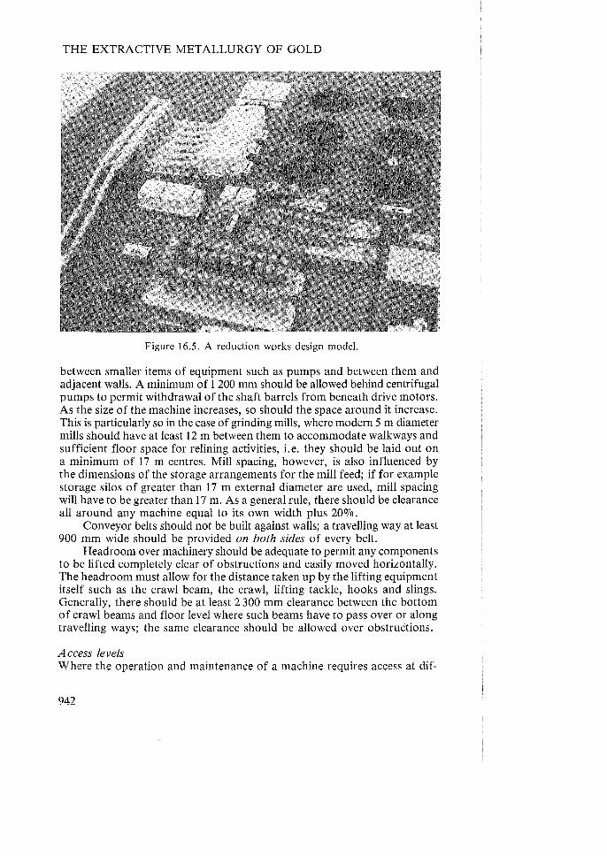
THE EXTRACTIVE METALLURGY OF GOLD
Figure 16.5. A reduction works design model.
between smaller items of equipment such as pumps and between them and adjacent walls. A minimum of 1 200 mm should be allowed behind centrifugal pumps to permit withdrawal of the shaft barrels from beneath drive motors. As the size of the machine increases, so should the space around it increase. This is particularly so in the case of grinding mills, where modern 5 m diameter mills should have at least 12 m between them to accommodate walkways and sufficient floor space for relining activities, i.e. they should be laid out on a minimum of 17 m centres. Mill spacing, however, is also influenced by the dimensions of the storage arrangements for the mill feed; if for example storage silos of greater than 17 m external diameter are used, mill spacing will have to be greater than 17 m. As a general rule, there should be clearance all around any machine equal to its own width plus 20%.
Conveyor belts should not be built against walls; a travelling way at least 900 mm wide should be provided on both sides of every belt.
Headroom over machinery should be adequate to permit any components to be lifted completely clear of obstructions and easily moved horizontally. The headroom must allow for the distance taken up by the lifting equipment itself such as the crawl beam, the crawl, lifting tackle, hooks and slings. Generally, there should be at least 2 300 mm clearance between the bottom of crawl beams and floor level where such beams have to pass over or along travelling ways; the same clearance should be allowed over obstruCtions.
Access levels Where the operation and maintenance of a machine requires access at dif-
942

PLANT DESIGN AND COMMISSIONING
ferent levels, platforms or galleries are usually provided, particularly when several similar machines are grouped together in one building. Examples of this type of machine are crushers and mills.
Machines of any appreciable mass have to be mounted on foundations sunk into the natural ground, so that normally ground level is the lowest access level. But except in the case of pumps and similar smaller equipment, operation is usually more convenient at one or more levels above ground. Crushers require at least one additional level above ground, and for the larger gyratory and cone crushers it is frequently convenient to provide two operating levels, the first being that at which crusher adjustment is carried out and the second that at which the feeders are situated. Likewise, operating and maintenance convenience of grinding mills and their associated classifiers normally require several platforms, the first slightly below mill centreline and completely encircling the mill to provide access for discharge sampling and also for relining operations, and for large mills a second at a little below the highest point of the mill but extending backwards from the mill feed end for easy observation of feed belt discharges and the interiors of feed hoppers. Local control panels can also be situated at this level, which is normally sufficiently high to allow good surveill;mce of the surrounding area as well as the mill itself. Cyclone classifiers can usually be located so that their spigots are accessible from this level. But good acccess to cyclone feed piping, valves, overflow samplers and vortex finders generally requires several additional platform levels. Where the installation comprises several adjacent units, the platforms would obviously be extended laterally to provide continuous levels serving the whole installation.
Frequent convenient stairway interconnections between levels must be provided, usually one complete set interconnecting all levels as directly as possible per mill. A personnel and materials lift should also be provided in a plant of any appreciable size.
The main operating levels for the various sections of the plant should be as nearly as possible at the same elevation, and should be interconnected to form a continuous patrol route through the plant. Control rooms should be on this level or easily accessible to it; alternatively, it is often possible to combine all control rooms into one from which all the main indoor and some outdoor installations can be observed.
Thickeners The essential requirements of good thickener layout are simplicity of feeding and overflow arrangements, simplicity of draining and good access. In South African gold metallurgy practice, thickening follows milling and the milled pulp can be either pumped or gravitated between mill and thickeners. The final mill product is normally cyclone classifier overflow, so that the pulp usually leaves the milling process at a sufficient elevation to permit direct gravity feeding of the thickeners, even allowing for sampling weirs and trash removal on the way. Direct gravity feeding has the obvious advantage of avoiding an intermediate pumping installation, which because of the large volumes involved has itself to be large. However, pump feeding does have
943

THE EXTRACTIVE METALLURGY OF GOLD
I VER T1cALi SPINDLE SPILLAGE PUMYS
No. 21 Thickener
--ttII------T
~ No 31",;'k'"'~r -m-- -~ No.' I n,;"'"'_r ---Itt--~ t I/~'f--'=T A
944
CAGED BALL I , NON-RETUiN VALVES
,
PLAN
SECTION A-A
CUT BACK TO PERMIT HANDLING OF STANDARD
PIPE LENGTHS
Figure 16.6. Conceptual layout of a thickener drainage and spillage system.

PLANT DESIGN AND COMMISSIONING
several advantages, including greater freedom in siting the thickeners and the possibility of including guard cyclones or other processing steps before the thickeners, and should be given due c.onsideration at the design stage.
Thickeners can be laid out in parallel straight lines in which the feed for each is tapped off a supply launder or pipe extending the entire length of each line, or in a 'grouped' arrangement fed from a central distributor; obviously, it is also possible to combine the two systems. The straightline arrangement will probably require less head between mill cyclones and thickeners and generally speaking will be simpler than the' grouped' arrangement from the feeding and overflow collection point of view when more than four thickeners are involved. However, with modern large thickeners, more than three or four are seldom required for the whole thickener installation, and this number can conveniently be accommodated in a single group which can be fed from a central distributor. Guard cyclones, if employed, can be accommodated in the distributor support structure.
Thickener underflow removal and drainage systems require careful design if they are to be satisfactory in operation. As thickeners increase in diameter, suction columns become impractically long if underflow pumps are placed outside the perimeter of the thickener tank, particularly if low underflow w/s is to be maintained. Consequently, modern practice is to place the underflow pumps, usually centrifugals, below the centre of the tank in the access tunnel, so that very adequate arrangements have to be made by way of spillage sumps and self-starting vertical-spindle spillage pumps to prevent underflow pumps from being flooded in the event of leakage into the tunnel.
Very careful attention must be given to the design of the thickener and tunnel emergency emptying systems to ensure that they will not themselves be put out of action in an emergency. Thickener tunnels should be isolated from each other either by making each a completely separate entity with its own emptying arrangement or by partitioning it off from any interconnecting trench or sump by a watertight wall. The bottom of such interconnection should be below the bottoms of the thickener tunnels so that the latter can only drain outward into it through non-return valves of the caged floating ball type; drainage columns should pass through the watertight wall if a common drainage pump is used for all thickeners. The walls of trenches and drainage pump chambers must extend well above ground level to prevent flooding by surface water, and important valves should be operable from ground level through extended spindles if necessary. Figure 16.6 shows a layout serving a cluster of four thickeners, although the same design principles would apply to a straightline layout using an interconnecting trench. Note that provision is made for the drainage of thickener contents through the side as well as the bottom of the tank; this is to enable the separate drawing-off of supernatant water and partially thickened pulp through the side drain and their disposal within the remainder of the thickener plant, while the thickened pulp can be transferred forward to the leach plant.
Thickener tunnels must be sufficiently wide to accommodate all the necessary pipe columns on one wall and leave enough width for the convenient movement of the largest pieces of equipment, probably the underflow
945
THE EXTRACTIVE METALLURGY OF GOLD
pumps, that will have to pass through the tunnel. For the same reason, the tunnels should be equipped with crawl beams spaced at least 2 300 mm from the tunnel floor. The edge of the tunnel roof at the entrance to the tunnel should be 'chamfered' back to permit the handling of standard length piping into the tunnel. Underflow pump suction connections and thickener drainage columns should both be equipped with two cut-off valves in series and should have permanent high-pressure water connections for easy clearing of chokes.
Thickener bridges, like tunnels, must be sufficiently wide to permit easy movement of machinery components and should also be equipped with crawl beams.
Thickener overflow collection systems tend to reflect the feed systems; that is, when the thickeners are laid out on the straightline system, the overflow collection system generally comprises a main collection launder for each line, while in the case of grouped thickeners, the overflow channels generally converge as a fan directly into the thickener overflow collecting tank or 'return water' tank.
In the straightline layout, it is possible to arrange for thickener feed, overflow and underflow systems all to be carried at different levels on the same structure over the thickener tunnel interconnecting trench, but care should be taken that no launder can overflow into another beneath it. Using this system, it is sometimes possible to arrange for under flow transfer pumps and return water pumps to be housed in the same building.
The best material for thickener feed and overflow and underflow collection systems seems to be concrete piping with compression ring type flanges and inspection slots running the length of each section to permit easy descaling of the pipe interior.
The use of one or more thickeners to serve as return water collectors can be strongly recommended; continuous operation of the rakes and underflow pumps is necessary to avoid damage to the rakes, but totally eliminates the necessity for the very labour-intensive and unpleasant manual cleaning of return water collectors.
Leach plant The current tendency is towards the use of propellor-agitated leach vessels of depth:diameter ratio of 2 or more, and of depths up to 22 m. To avoid excessive short-circuiting of pulp in continuous leaching, at least six vessels should be used in series, and preferably eight (see Chapter 6). Thus modern leach plants are arranged in parallel strings of eight or more tanks, and the layout must provide sufficient head between tanks to ensure that peak flow requirements can be met, and also allow the by-passing of one or two tanks in each string when necessary.
To reduce the physical distance between feed and discharge points of each string and thus the difference in elevation between these points, it is usual to locate alternate tanks on two parallel centrelines, with pulp passing back and forth between the two half-sets as it flows towards final discharge. The tanks can be arranged on either a square or a triangular grid, as shown
946

PLANT DESIGN AND COMMISSIONING
Inflow
Outflow
SQUARE LAYOUT
Inflow
Outflow
TRIANGULAR LAYOUT
Figure 16.7. Two types of leach vessel layout.
in Figure 16.7. The triangular arrangement is recommended as being more versatile. Normally, corresponding tanks in the two half-strings are located at the same elevation, but succeeding pairs are located at successively lower elevations. Alternately, the tanks can all be sited at the same elevation; although this results in a progressive diminution of effective volume of the successive tanks, it does have the advantage of preventing overflows as the result of power failures.
Open launders and simple drop-in cut-off gates are preferable to pipes and valves for tank interconnections from the point of view of ease of clearing chokes, but obviously they must be sufficiently deep to accommodate the maximum change in pulp level likely to occur in operation. Interconnections must be kept as short as possible, and where relative movement between tanks is expected, should incorporate suitable means to accommodate
947

THE EXTRACTIVE METALLURGY OF GOLD
this. A by-pass column running the whole length of the installation and connected to each tank by a valve is sometimes provided, but is very expensive in valves, and is unnecessary if sufficient intertank connections are made as shown in Figure 16.7.
Leach vessels should be contained in a bunded area graded at 2 Yz 0J0 towards a sump connected to drainage pumps outside the bund. Joints in bund concrete should be sealed with polyurethane before machinery installation. Emergency draining of tanks is done directly into the bund which should be capable of containing at least two leach vessel volumes. Provision should be made for reaching and operating drain valves even when the bund is full. Non-emergency emptying of tanks can be through a drainage pipe system delivering directly to the above-mentioned drainage sump although the large change in suction head can cause pump operation difficulties, and drainage via the bund might be preferable. Leach vessels should be provided with manholes on hangers through which the tank can be entered from ground level when empty, for inspection and clearing.
In the case of mechanically-agitated vessels, some means must be provided for raising and lowering heavy components such as impellers, shafts, gearboxes and motors between ground level and tank top. In the past this provision has taken the form of a crawl beam and crawl on each tank but recent large installations have incorporated tower cranes for this purpose (Anonymous, 1985).
Carbon-in-pulp plants The carbon circuit in a carbon-in-pulp plant is a closed loop with the carbon moving countercurrent through the pulp in part of the loop, then being separated, eluted, regenerated and finally returned to the tail absorption vessel. Carbon-in-pulp absorption vessels can thus be laid out on a straight line with the elution and regeneration plants somewhere alongside or at either end of the absorption line, or the latter can be bent into a U with the carbon treatment section at the top of the U. Several U-shaped strings of absorption vessels, starting and finishing at the central carbon treatment building, can radiate from this building in which all pulp transfer pumps and ancillary equipment, as well as the carbon treatment equipment itself, can be housed. A control room can be situated at the top of the central building with a good view over all the absorption tanks, so that a very compact and easily supervised plant results, as seen in Figure 16.8.
The disadvantage of the U layout is that it is less flexible as regards expansion than the straightline arrangement, in which space can be provided at the ends or alongside the original lines for further tanks.
As with leach vessels, there must be sufficient fall between succeeding tanks to cater for peak flow rates and also the by-passing of tanks as required, but absorption vessels normally require additional head room to accommodate the intertank screening arrangements. Adequate lifting and transport arrangements must be provided over the tanks for handling agitator mechanisms, shafts and propellors, and the interstage screening equipment whether static or mechanical. The trend in large plants is towards tower cranes
948

PLANT DESIGN AND COMMISSIONING
Figure 16.8. A carbon-in-pulp plant using the U-type layout.
for this purpose. Carbon-in-pulp absorption vessels should be located in a bund with ade
quate spillage and drainage facilities. Bund floors should slope at 2070 or more towards spillage pump intake sumps, the pumps being located outside the bund. Joints in bund concrete must be sealed with polyurethane. Bearing in mind the relatively high concentration of gold in loaded carbon, and the easy transportability of the carbon, the carbon-in-pulp plant should be regarded as a high security area and be enclosed within its own security fence with guarded entrance and self-contained facilities so that movement of personnel in and out of the security area is minimized. The plant for recovery of gold from the.carbon-in-pulp eluates, whether by zinc duct precipitation or electrolysis, should be located adjacent to the smelthouse, and the eluates piped to it,rather than incorporating the recovery section in the carbon-inpulp plant and transporting very high grade solids from it to the smelthouse.
Filter plants With the advent of carbon-in-pulp technology, it seems unlikely that any further large filter plants will be built for recovery of gold bearing solution from leached pulp. However, it is possible that filter plants might still be built for recovering water, cyanide and lime (and possibly even some gold) from carbon-in-pulp tailings, and the following pointers are offered with this possibility in mind.
Disc and drum filters are normally mounted on concrete foundations sunk into the natural ground level. However, the foundations should be sufficiently high to bring the machines up to a convenient distance above an
949

THE EXTRACTIVE METALLURGY OF GOLD
operating floor which will be the first level above ground. Drum filter pans are frequently of concrete cast integral with the foundations. Siting the filters above ground allows for the installation of drainage sumps, conveyor belts or repulpers, and ancillary equipment such as filtrate and vacuum pumps, at ground level, preferably where they can be observed from the operating level, leaving the latter uncluttered. If a conveyor ,belt is installed for the removal of discharged filter cake, it should be possible to walk along its entire length between filter foundations and belt stringers in order to reach conveyor idlers for servicing; similarly, any other cake handling equipment should be easily accessible for maintenance. Any weightometer installed on the belt must be mounted well clear of the nearest filter, which generally means siting the repulper well away from the filters and locating the weightometer in the gap between filters and repulper. The repulper tank should be of concrete rather than steel, and it should discharge by overflowing a weir, never by direct connection to a pump, except for drainage purposes. Weir overflow also provides a sampling point, and should be designed as such. The section of belt between the last filter and the repulper should be built over a narrow extension of the main filter drainage sump which reaches to the repulper so that the latter can overflow into it in emergency. The belt must be well washed and the washings should gravitate directly into the repulper.
If wash sprays or wash distribution troughs are fitted to filters, they should be visible from the valves controlling them to facilitate wash adjustment. Access must be provided to the sprays or distributors for cleaning purposes, and the valves, together with all other valves and controls, must be conveniently located on the operating floor.
Idlers on conveyor belts carrying filter discharge cake should have cantilevered closed-end rollers to provide increased protection against entry of pulp into bearings. The rollers should preferably be rubber covered. Crawl beams and lifting equipment must be provided over all filters.
Belt filters do not require any drainage or emergency emptying arrangements, but do tend to produce large quantities of low-density spillage resulting mainly from leakage of sealing water. They must therefore be sited over impervious floors graded towards spillage pumps. Foundations for belt filters are normally very much less massive than for drum and disc filters, comprising essentially footings for the steel framework. The necessary headroom for the repulper and the return belt rollers has therefore to be provided by making the framework columns sufficiently long. This headroom requirement is usually several metres on all except the smallest filters. Consequently an operating floor above ground level and surrounding each filter is usually required. As with drum and disc filters, ancillary equipment should be placed on ground level, but well clear of the filters themselves because of the very wet conditions pertaining. However, to minimize duct lengths, belt levitation fans are best sited on the operating floor adjacent to the filter.
The main belt on a large belt filter is an extremely massive item, and good provision must be made for handling it and also the filter cloth itself, during renewal operations. This generally implies easy access to the feed end of the filter, good mechanical handling aids and plenty of space between
9<;0
PLANT DESIGN AND COMMISSIONING
filters. The changing of rollers and shafts is also facilitated by adequate interfilter spacing; the length of these rollers approximates the width of a filter, so that the spacing between filters should be filter width plus 20070. Lifting services in belt filter bays are best supplied by a single gantry crane covering the entire area.
Smelthouses The main criteria in smelthouse design ·are:
(1) minimization of manual handling, (2) provision of a pleasant environment, particularly with regard to heat,
fumes and lighting, (3) high security.
The chief source of feed to the smelthouse is normally a precipitation stage, either zinc dust or electrolytic, while a frequent secondary source is a gravity concentration stage located within the milling circuit. The smelthouse should be so situated that the products from both these sources, which are very high grade, can be delivered into it without manual handling.
Generally the smelthouse personnel are responsible for carrying out the 'clean up' or removal of accumulated gold precipitates from the vessels in which the precipitation takes place and its transfer to the smelthouse. This, together with the fact that in many plants the precipitate is the only feed to the smelthouse, has resulted in the smelthouse generally being located in the cyanide plant area rather than in the mill area.
It is usually possible to site the precipitation units immediately adjacent to the smelthouse and at a sufficient elevation to permit gravitating the precipitate through pipes directly into receiving vessels in the smelthouse. In fact, electrolytic precipitation plant can be sited within the smelthouse itself, but visible and controllable from outside by shift operating staff. Placing the smelthouse within the cyanide plant almost automatically ensures that concentrates from the mill will be delivered by pumping, so that both precipitated gold and concentrate will reach the smelthouse without manual handling.
The smelthouse equipment should be so laid out that the gold bearing materials being processed follow as logical and direct a sequence as possible through it, with as little manual handling as possible. Slurries should be pumped or gravitated between stages, and cakes and other products which cannot be pumped should be handled by chutes or in containers travelling on roller tracks or wheels or suspended from overhead tracks. In larger plants, such as those generally encountered on the Witwatersrand and Free State goldfields, slag handling is facilitated by the fact that smelting is now invariably done in electric submerged arc or induction furnaces, pouring of the melt being done through a cascaded train of moulds which overflow from one into the next so that the slag leaves the cascade in a continuous stream while pouring is in progress. This arrangement is very well suited to continuous granulation of the slag by allowing it to fall into water flowing down a launder into a pump sump below floor level; from this sump the granulated

THE EXTRACTIVE METALLURGY OF GOLD
slag and water are pumped continuously to a conical bottom holding tank fitted with an overflow launder and sited within the smelthouse itself; the settled slag, after draining off the water, can be run out into bags for transport.
Pleasant working conditions within the smelthouse are ensured by making it as spacious as possible so that personnel are not obliged to remain continuously in the immediate vicinity of hot furnaces, and by providing good ventilation and lighting. The main task of the ventilation system will be the efficient removal of dust and fumes from furnaces, and this will usually require the provision of collecting hoods over furnaces and other sources of dust and fume, and exhausting these to atmosphere through filters and fans. A smelthouse can be a very cold place in winter when no furnace is operating, and some means of heating it at those times should be provided.
The smelthouse should be illuminated during daylight by glazed southfacing sides of sawtooth roof sections; windows in walls should be avoided. Artificial lighting at night must provide sufficient illumination to enable the entire interior of the smelthouse to be easily visible from external observation points.
Security is enhanced by constructing all smelthouse walls, at least up to 3 m above ground level, of reinforced concrete or brick, by providing as few entrances as possible and equipping these with double-locked stout steel external doors and steel grille internal doors. One external door should be sufficiently large to admit road transpott so that this can be loaded and offloaded within the completely locked smelthouse. The entire interior of the smelthouse should be observable through suitably guarded openings from the adjacent building. These observation openings should preferably be located on the continuous patrol route of the plant shift operators. Changehouse, toilet and eating facilities should be provided within the smelthouse so that movement in and out of the smelthouse can be minimized. The strongroom, of which walls, floor and roof should be of heavily reinforced concrete at least 300 mm thick, should have a single top-grade door equipped with treble combination locks and 7-day time lock. If any of the walls of the strongroom forms part of the outer wall of the smelthouse itself, care must be taken that the exterior of such wall is kept completely unobstructed and under frequent surveillance, and above all that it should not be a common wall with some relatively unfrequented and closed-off area such as a substation or storeroom from which an attempt could be made to gain access to the strongroom. Smelthouse acid treatment vat vent ducting should be of timber, and definitely not of plastic on which static electric charges can be generated by the passage of gas.
SpiUage handling This is a very important aspect of plant design, but is frequently overlooked. A clean plant is essential to efficiency and cannot be achieved if spillage handling is not designed for. Care must be taken to ensure that spillage can be dealt with in all areas of the plant by hosing-down of adequately sloped floors to spillage launders and! or pump sumps and directed to the appropriate

PLANT DESIGN AND COMMISSIONING
re-entry points in the circuit. This is especially true in reagent make-up areas.
Drainage In terms of Government Notice R287 of 20 February 1976, paragraph 10, the discharge of any spillage into any evaporation dam, storm water drain or other waterway on the mine property is illegal. Therefore provision must be made in the plant layout to keep plant spillage or overflows of any description, including pulp, water, solutions and reagents, from entering the stormwater drainage system. This usually calls for the siting of tanks within bunded areas, and the grading of floors of machinery areas so that all spillage is directed inwards into internal spillage systems. Overflows of water, particularly those from the mill water system which can be of considerable volume, are usually best dealt with by the provision of an overflow dam sited at the lowest point of the plant area, and from which the water can be reclaimed for re-use in the plant.
16.4.5.2 Construction details Buildings Walls - The preferred materials for walls at least up to first floor level are brick, cement block, or reinforced concrete for high-security areas. Above this level, corrugated sheeting of galvanized steel has been usual in the past although the recently introduced 3CR12 steel is probably more cost-effective over its service life despite the fact that it should be painted. 3CR12 is however not strongly resistant to chloride ion attack, and in such conditions corrugated plaster sheeting should be used. Roofs - Possibly the most cost-effective material is corrugated or !BR sheeting in 3CR12 steel, even though this will usually require painting externally for appearance's sake. In areas of high chloride ion concentration, reinforced plastic is preferable, although the possibility of hail damage must be kept in mind. Windows - Areas not requiring high lighting levels can usually be adequately illuminated in daytinle by translucent fibre-reinforced plastic corrugated sheet panels in walls and roofs. Where high lighting levels are required, glazing the steeper flanks of sawtooth roof sections will usually be adequate for top floors or single-floored build,ings, but vertical strip fibre-glass wall panels will be required on lower floors. Where damage by hail is possible, wire reinforced glazing should be used, and ease of cleaning and repair must be provided for. Main structural members - In the past, structural steelwork has normally been of carbon steel. However, a selective range of structural sections in 3CR12 chromium-bearing corrosion resistant steel is now available, and although this material is considerably higher in first cost than carbon structural steel, its' life cycle cost' , i. e. the cost per unit of service life taking into account the much reduced maintenance costs, could well show it to be competitive with the traditional material; it should be considered for any new plant construction. Floors - Main building floors and operating levels should be of reinforced
9"'1 JJ

THE EXTRACTIVE METALLURGY OF GOLD
concrete. They should preferably not be level, but should be graded at one per cent to drainage points. Under and around pulp handling equipment, floors should be graded 60/0 towards spillage channels. Auxiliary floors and interconnecting galleries less used than main operating floors can be of reinforced concrete if wet, with egg-crate-covered openings if necessary to permit surveillance of equipment on floors below. If dry, auxiliary floors can be of steel egg-crate, but these should be raised about 30 mm above supporting steelwork by angle iron welded to the latter to prevent the formation of dirt-collecting pockets. Stairway treads - These are best made of steel egg-crate 300 mm wide, and 200 mm rise per tread. Handrails - Stanchions should be solid castings and the rails solid rod, not piping. Top .rails should be 1 000 mm above floor level with a second rail about 500 mm above the floor. Steel kicking plates 150 mm high should be provided under handrails. Sumps - The essential function of a sump is to provide storage capacity to absorb differences between inflow and outflow rates. In the case of a sump drained by a centrifugal pump, the changes in fluid level resulting from differences between inflow and outflow result in some degree of automatic level regulation by adjusting the total head on the pump and hence its pumping rate. The primary problem in sump design is therefore so to configure and size the sump that changes in fluid level, in conjunction with the pump head capacity characteristics, can bring about the necessary changes in pumping capacity without allowing the sump either to overflow or to run empty.
One solution to the primary problem is to make the sump very large in relation to the inflow so that even a very big difference between inflow and outflow can be at least temporarily accommodated. This, of course, is the situation in the case of drainage sumps and bunds, but in the case of sumps for continuously-operating pumps it is not a practicable solution, firstly because it is uneconomic of space and materials and secondly because, in the case of pulp handling sumps, settlement and possible subsequent breaking away of the solids cause major operational problems. A secondary problem is therefore to design the sump with as little dead volume and opportunity for solids settlement as possible.
The general procedure for sump design is therefore to size the sump to handle the maximum surges anticipated (and this can in some cases be minimized by interlocks between pumps drawing from sumps and equipment delivering to the sump) and then to decide on an effective depth which will allow, in conjunction with the pump characteristic, some measure of automatic pulp level control. To avoid solids settlement, sumps should be restricted in horizontal cross-section area, and their bases should be graded towards pump suctions at not less than 40° to the horizontal. The suction column should continue at this slope through the suction valve and then sweep to the horizontal immediately before meeting the pump. All corners, both vertical and horizontal, of sumps handling suspensions should be well rounded to minimize solids lockup. Pulp pump suction columns should have high pressure water connections on both sides of the suction valve, and all suc-

PLANT DESIGN AND COMMISSIONING
tion columns should incorporate at least one angled flange to facilitate valve removal or disconnection of the pump.
The bases of sumps must be sufficiently elevated above pump intakes to ensure a net positive suction head on the pump under all flow conditions to prevent pump cavitation.
The preferred materials for sumps handling fluids only are steel and concrete, if necessary protected against corrosion by suitable linings. For pulp sumps also, either steel or concrete can be used, but steel almost always requires rubber lining internally and frequent painting externally, and from the viewpoint of minimum maintenance, concrete is preferable. Even concrete, however, must be protected against erosion by some form of lining if pulp is allowed to impinge directly on it, and concrete sumps are of course very difficult to modify once built. Suction columns connected to concrete sumps should not be bolted to sump walls by studs; they should be a snug fit inside a flanged stainless steel nozzle set in the concrete and pass through this nozzle to the interior of the sump, being retained by a flange bolted to the nozzle flange. All sumps should have drain valves connected to the lowest point. Launders - Materials used for launders are usually carbon steel plate, carbon steel pipe or wood plank. When necessary, these materials can be protected from abrasion by 5 mm of 50 shore natural rubber. However, all the construction materials mentioned require painting for external protection, and concrete.piping has been found to be a very satisfactory low maintenance alternative which does not require painting although it needs more support structure than the traditional materials.
Concrete piping for launders should be joined with compression type flanges rather than concrete collars, and should be of the slotted variety for ease of inspection and descaling. Any closed type of launder should have frequent inspection openings, at least of the same cross-section dimensions as the launder itself.
As regards launder shape, a flat-bottom configuration is obviously easiest to construct from flat materials such as plate or planks. However, the Chezy formula
Vc = C(Rh.S)Y' (16.7)
where Vc = pulp velocity, Rh = hydraulic radius (= stream cross-section area/wetted perimeter) S = the launder slope C = a constant for a given Rh'
shows that pulp velocity is increased both by increasing hydraulic radius and by increasing launder slope. C varies almost linearly with Rh' so that Vc varies nearly as Rh3
!2. Therefore, for maximum economy of materials, the optimum launder shape is that having the greatest Rh with the smallest other dimensions. This condition is met by a semi-circular channel running completely full. However, some freeboard or means to prevent overflow must be provided, and this can conveniently be done by using a pipe running half full at maximum flow rate.

THE EXTRACTIVE METALLURGY OF GOLD
An excellent launder design method is given in a paper by Green, Lamb and Taylor (1978), although it must be pointed out that the method is aimed at deriving the necessary launder dimensions and slope to maintain a pulp velocity sufficient to prevent solids settlement; it does not deal with the initial period when the pulp is accelerating from virtually zero to design velocity. Steeper slopes than those given by this method are necessary to prevent solid settlement during the acceleration phase.
Piping Water, solution and pulp pipes are normally made of carbon steel with wall thicknesses selected to accommodate the required maximum pressure. High density polyethylene piping is, however, being increasingly used for fluids and fine pulps where the danger of damage resulting from external events is small, e.g. in buried pipelines. Columns carrying coarse, abrasive solids will require protection by rubber lining, or they can be made of armoured rubber hosing if sufficient support and adequate pressure rating can be provided. Pipe lengths should be joined with flanges, and not welds, to enable easy assembly and dismantling. Pipelines subject to scale build-up, for example those carrying mill circuit water and residue pulp, should incorporate means for easy descaling. Quite extensive pipe systems, such as the mill water reticulation, can be descaled by taking them off-line, and filling them with a 3070 inhibited hydrochloric acid solution, taking care to provide safe escape routes for the evolved gas. For long columns such as residue pipelines, descaling is freq~ently done by means of go-devils or hedgehogs. These are wooden spheres carrying a large number of partly inserted screws on their surfaces, or they can be made of serrated steel semi-circles welded together along their straight edges to simulate a sphere. Go-devils or hedgehogs are inserted into the empty pipeline through tee branches which can be closed by means of blank flanges or valves. Alternatively, if the branch is equipped with two valves with sufficient distance between them, the go-devil can be inserted into the column with the latter onstream. The fluid flow forces the go-devil along the column while its surface projections cut away scale accumulations.
Pipeline design - In the case of pulp pipelines, the design objectives are firstly, given the required volumetric flow rate and solids size distribution, to calculate that pipe diameter which will result in the necessary minimum pulp velocity to prevent solids settlement. The second objective is then to determine the pressure loss per unit pipe length, in order to determine the necessary pipe slope for gravity flow or the necessary pump delivery pressure when designing pump delivery columns. Obviously, in the case of pipelines handling fluids only, the first objective does not apply.
A procedure for pipeline design is given in Appendix 16.1 to this chapter.
Pump selection The problem in pump selection is first to calculate the total dynamic head on the pump at the necessary velocity to prevent solids settlement (as determined in Appendix 16.1), and then from makers' catalogues, to select a pump
95(')

PLANT DESIGN AND COMMISSIONING
capable of delivering the required flow against this head. The pump speed and drive power requirements will then also be obtainable from the maker's data. A method for pump selection is given in Appendix 16.2 to this chapter.
16.4.5.3 Piping and Instrumentation Diagrams Concurrent with detailed plant layout drafting, Piping and Instrumentation DIagrams (P & IDs) are prepared. These show each and every piece of equipment which is connected to any other piece by piping or launder, and all interconnecting, inc·oming and outgoing pipelines and launders throughout the plant; that is, duplicated items of equipment and interconnecting flow are all shown. This contrasts with the flowsheet, where duplicated equipment and flows are represented by one symbol only. All instrumentation is also shown as well as its connections to the plant equipment, using a standard representation. Each pipeline and launder is then allocated an identifying code and number, and is labelled on every P & ID sheet on which it appears; this identification enables easy tracing of the pipeline through any number of sheets. The P & IDs thus become very useful aids to detailed design; in fact, in the design of any except the simplest plant, they are indispensable.
16.4.5.4 The Definitive and Revised Cost Estimates When process design, P & IDs and detailed plant layout drafting have been completed, it will be possible to call for tenders for the supply of all but minor equipment and for the performance of all the significant construction work. This will make available cost estimates for these two major components of the overall project, and so enable preparation of the Definitive Cost Estimate, that is, an estimate accurate to within ± 100/0. The subsequent completion of all detailed design work will enable refinement of the Definitive Estimate to within ± 5 % to produce the Revised Estimate.
16.5 Plant Construction and Commissioning 16.5.1 Metallurgical involvement in the construction phase It is highly desirable that the official who will be in charge of plant operation, and, if possible, his second-in-command, should be involved in the design, construction and commissioning process at as early a stage as possible, preferably as part of the metallurgical component of the Project Team. This will ensure their complete familiarity with the design background and operating philosophy of the plant. But as the design process gives way to the construction phase, the plant manager des.ignate and his assistant should move onto site, or at least make frequent site inspections. They should have regular contact, possibly at daily meetings, with the construction supervisor to report and obtain correction of any design and construction errors they observe and generally to act as process advisors to the construction team to ensure that the plant will be capable of being safely and efficiently operated when startup commences.
957

THE EXTRACTIVE METALLURGY OF GOLD
16.5.2 Preparation for commissioning Concurrently with the construction phase, or even earlier if possible, the manager designate will have to devote much of his time to preparing for plant startup, for this will be uniquely his responsibility. In conjunction with the design and construction personnel he will have to prepare the startup timetable; in conjunction with maintenance and buying departments he will have to ensure adequate supplies of stores, reagents and spares at startup time; and above all, he will have to ensure adequate manning of the plant by trained personnel. As part of the training process, operating manuals will be required, and the manager designate will be involved in the preparation of these and also in the arranging of training programmes, possibly in existing plants, for the plant personnel. The drawing up of log sheets and arranging for proper record keeping and reporting of plant operations will also be his responsibility. The manager designate will also be required to establish a procedure for takeover of sections of plant from the construction personnel as they are completed; this is essentially a safety precaution to ensure that there is no misunderstanding as regards who, at any particular time, is in charge of any particular section of the plant and consequently is responsible for safety in that section. A very comprehensive exposition of the duties of the plant manager in relation to startup has been given by Fulks (1982). Fulks deals with American chemical plant practice and uses the term 'plant engineer' rather than 'plant manager', but his recommendations are of direct relevance to South African gold plant construction.
16.5.3 Commissioning 16.5.3.1 Personnel Commissioning is best carried out by a specially-assembled commissioning group under the plant manager and comprising metallurgists, engineers with artisan backup to carry out minor alterations and trouble-shooting expeditiously, and experienced operating personnel under a plant foreman. No attempt should be made to start up a new plant with inexperienced personnel.
16.5.3.2 Cold commissioning The construction crews normally hand over each section of the plant when it has been 'mechanically completed', i.e. when the buildings, structure and equipment are all in place and connected up mechanically and electrically according to the drawings and the equipment has been correctly lubricated, checked for operation in the sense that it will start and run when required to do so, and motors will turn in the correct direction. The commissioning team should not accept any portion of the plant from the construction crews until it is satisfied that the section has been completed at least to the stage where commissioning can commence with a reasonable hope of success and above all that it is safe. Having taken over a plant section, the commissioning team then is responsible for that section and can proceed to the first stage of its task, namely 'cold commissioning'. Cold commissioning means running the section without process material in it. For example, in commissioning a mill circuit, the mills, feed belts, etc. would be run empty at normal
958

PLANT DESIGN AND COMMISSIONING
operating speeds, but the mill water reticulation services would be completely functional (which implies that the thickeners and return water system would already be operational and filled with water) and the normal flows of dilution water would be passing through the mill-classifier circuit, pumps, pipes, launders, etc. Cold commissioning is the stage at which unsuspected construction debris in pipes and elsewhere is discovered, leaking pipe joints are corrected, conveyor belts are trained, automatic controls can be roughly set, overheating machinery detected and rectified and so on.
In short, it is the stage in which the plant section is brought to the state where it appears to be capable of handling the process stream reasonably efficiently, safely and continuously, but without actually having handled normal process material. The plant manager must keep in direct contact with the commissioning process and should have at least a daily meeting with the construction supervisor to report progress, and by means of 'punch lists' request rectification of construction faults which cannot be dealt with by the engineering personnel attached to the commissioning team. At these meetings also, any necessary temporary handing back of sections for construction fault rectification can be arranged.
16.5.3.3 Hot commissioning After all obvious faults which would prevent the safe and reasonably efficient handling of the process stream have been eliminated, 'hot commissioning' can commence. This is the crucial stage at which the actual process material begins to pass through the plant and at which it becomes evident whether or not the effort of the preceding months and years is to be crowned with success. Normally, feed rates are kept low at the commencement of hot commissioning and gradually built up as faults are eliminated and the plant settles down to normal operation. The importance of careful record keeping should not be overlooked, even at this stage. Inevitably, design faults will come to light during hot commissioning, but if the design work has been careful and guided by experience, the faults should be minor and relatively easy to correct. However, if, unhappily, major faults become evident, they must be faced and dealt with boldly to reduce to the minimum the loss of production and profit while the fault is corrected. Quick decision-making by the plant manager and his advisors is necessary, but decisions must be tempered by due recognition of the fact that at this stage the plant will probably not have attained designed conditions at all points; alterations must not be rushed into which would be made unnecessary by correct functioning of the process at some other point. In other words, treat causes, not symptoms.
The plant manager will obviously be heavily involved in hot commissioning but must maintain his close liaison with the construction supervisor and must also keep his fellow heads of department and company management informed. Should major alterations become necessary, then of course further work will be required by the design section of the construction organization, and the plant manager will have to make an input to this.
959

THE EXTRACTIVE METALLURGY OF GOLD
16.5.3.4 Some practical commissioning tips (1) If possible, commissioning should be carried out on waste rock to reduce
the value of lockup and loss due to incorrect processing. (2) Avoid having ore, reagents, etc. in storage for extended periods before
plant startup. The properties of these materials can be adversely affected during storage so that eventually startup has to be commenced with material for which the plant was not designed. Also fines can set hard and become extremely difficult to move after extended storage.
(3) Only partly fill storage facilities such as stockpiles, bins and tanks before startup. Stockpiles, in particular, segregate badly as they are filled, so that unless drawoff occurs reasonably concurrently with filling a large core of fines can form which can seriously affect plant operation and require a long time to eliminate. Furthermore, if storage has to be emptied for fault correction, obviously the less material to be handled the better.
(4) Crushers should be set somewhat coarser than designed to begin with and gradually 'pulled up' to correct setting to avoid choking and damage if they are not able to handle actual operating conditions.
(5) Commence commissioning on manual control and gradually introduce automatic control as operation settles down.
(6) Run-of-mine mills should initially be fed dry (i.e. without discharge) at the highest rate at which rock can be got into them. This is in order to build up a pebble load as quickly as possible and to avoid pipeline blockage with coarse discharge. When the power draft reaches a maximum and commences to decline, the feed rate should be reduced to hold the power at maximum and dilution water opened. Steel grinding media should not be added until a satisfactory pebble load, both as regards quantity and size distribution, has been built up. In particular, avoid adding steel if the initial feed is fine, as the steel will simply retard the buildup of a pebble load. It is general experience that large run-ofmine mills require as much as six months before they achieve efficient operation.
(7) Have a range of sizes of cyclone spigots and vortex finders available to enable quick changes for rapid optimization. This applies particularly to spigots, whose size is more critical than that of vortex finders. Startup vortex finders need not be rubberized as they will probably be changed before wearing out.
(8) Thickeners should be filled to overflowing with water before startup otherwise the incremental water lockup before they overflow can exceed the drawdown of the return water tank and the mill water system can run empty.
(9) Thickeners should not be circulated during startup. Because of the higher settling rate of the coarser particles, circulation can cause the concentration of sand in the settled pulp which in turn can cause rake overload and tripout. It is better to keep the underflow pumps completely stopped with occasional short spells of running (without circulating) to avoid underflow system blockage, until underflow
960

PLANT DESIGN AND COMMISSIONING
water: solids has diminished sufficiently to permit continuous drawoff. (10) Remember to fill tanks and sumps which would normally contain recir
culated solutions required in the process, with a suitable temporary substitute to enable the process to get started. Normally clean water is satisfactory.
16.5.3.5 Acceptance runs Where the design and/ or construction of the plant have been carried out by some organization other than the owners, it is usual to include in the contract some form of' acceptance run'. During this, inputs and operating conditions of the plant are held as close as possible to those specified in the Process Design Criteria (see Section 16.4.3.1), and a determination is made as to whether the plant is then able to attain the specified operating and output targets. Obviously, time has to be allowed for overcoming possible initial faults and shortcomings, and a mutually agreed commissioning period may be specified in the contract. The contract will state the penalties to which the design! construction organization becomes liable if the plant does not meet the Design Criteria within a specified time, and possibly also contain 'incentive clauses' which lay down rewards for beating specified requirements, usually as regards date of acceptance. A very important point in drawing up the acceptance clauses is that the acceptance criteria should be capable of being measured and that they be very carefully specified and understood by both parties to the contract. For example, it is useless to specify what the characteristics of a certain process stream shall be, when in practice it is impossible to determine them, at any rate to the necessary degree of accuracy. Also, differences of interpretation can result in conflict situations between the parties, and great efforts should be made to avoid them by careful and thorough statement of the acceptance criteria.
16.6 Conclusion This chapter has given a necessarily very condensed scheme for the systematic design of a South African gold extraction plant, together with design information and procedures and some pointers to the actual commissioning process. If the design metallurgist conscientiously follows the route laid down, the probability of achieving the objectives mentioned at the commencement of the chapter, namely a plant brought into production on time, at designed capacity and efficiency, and within budget, will be very high, and the achievement will be one of which the metallurgist may be justly proud.
16.7 References Anonymous (1985). Cranes cut costs at Ergo. South African Mining World, 4(10), 26-29. Barnea, E. (1977). New plot enhances value of batch thickening tests. Chemical Engineering,
84(18), 75 -78. Dahlstrom, D.A. and Purchas, D.B. (1957). Scale-up methods for continuous filtration equip
ment. Institute of Chemical Engineers, London. Dillon, V.A. (1970). Special features of the Kinross Mines, Ltd. reduction plant. In Mineral
961
THE EXTRACTIVE METALLURGY OF GOLD
Processing and Extractive Metallurgy, edit. M.J. Jones, pp. 485 - 508. LM.M., London. Fulks, B.D. (1982). Planning and organizing for less-troublesome plant start-ups. Chemical
Enginering, 89(18), 96-106. Green, H.R., Lamb, D.M. and Taylor, A.D. (1978). A new launder design procedure. Mining
Engineering, (A.LM.E.), 30, 1210 -1216. Lamos, A.W. (1982). Liberation of gold grains from ores by chemical fusion. Research report
12/83, Chamber of Mines of South Africa Research Organization, Johannesburg. Manssen, L.P. (1983). Financial evaluation of mining projects: is common practice enough?
Mining Engineering, (A.l.M.E.), 35, 601 - 606. Moncrieff, A.G. (1963). Theory of thickener design based on batch sedimentation tests. Trans.
I.M.M., 1963 -1964, 73, 729 759. Osborne, D.G. (1975). Scale-up of rotary vacuum filter capacities. Trans. I.M.M., 83,
C158 - C166. Pownall, J.H. (1962). Grindabilit,y test procedure and ball-mill size selection. Mineral Process
ing Information Note No. 3. Warren Spring Laboratory. Department of Scientific and Industrial Res~rch, London.
Ruhmer, W. T., Svoboda, O. and Wilson, B.M. (1984). South African costs of equipment for the metallurgical industry, 1984. Report M212, Council for Mineral Technology, Randburg, South Africa.
Sproesser, W.D. (1980). Models speed plant design. Chemical Engineering, 87(6), 113 -116. Stermole, F.J. (1982). Economic Evaluation and Investment Decision Methods, 4th edn. In
vestment Evaluation Corporation. Stermole, F.J. (1984). Personal skills: economic analysis of mineral and energy investments.
Mining Engineering (A.l.M.E.), 36, pp. 143 - 146. Wild, N.H. (1976). Return on investment made easy. Chemical Engineering, 83(8) 153 -154. Wild, N.H. (1977). Program of discounted cash flow return on investment. Chemical Engineering,
84(10), 137 - 142. Wildhelm, J.H. and Naida, Y. (1979). Sizing and operating continuous thickeners. A.LM.E.
Society of Mining Engineers, preprint 79 - 30.
962

PLANT DESIGN AND COMMISSIONING
APPENDIX 16.1
Pipeline Design The following procedure for pipeline design has been supplied by P.R. Bailey, Consulting Metallurgist, Gencor Ltd, to whom grateful acknowledgement is made:
(1) Determine solids and pulp relative densities (rds and rdp)' and solids size distribution down to 30/tm.
(2) Calculate required pulp volumetric flowrate Q, in litres per second. (3) Calculate the solids concentration in the pulp by mass, using
C = rd/rdp - 1) m rdp(rds - 1)
(16.8)
(4) Determine the transport medium relative density, rdtm • For quartzitic ore of rds = 2,7 it is assumed that all particles smaller than 30 /tm are in permanent suspension and may therefore be regarded as part of the transport medium. The corresponding size for solids of relative density other than 2,7 is given by
Suspension size ds (/tm) = 2d' 7
x 30. r s
rd/mass fraction < dJ(rdp - 1) + (rds - rd~ Thenrd = ----------------~~------------~ tm (mass fraction < dJ(rd - 1) + (rds - rd~
(16.9)
(16.10)
(5) Calculate solids concentration by volume in pulp, Cv' Cv is normally given by
(16.11)
but for the purposes of step 7, the following formula which corrects for rdtm is used:
Cv(cOrrected) = rd - C ( d d) s mrs-rtm
(16.12)
(6) Determine dso' the size in micrometres passing 50070 of the solids, from the cumulative size distribution.
(7) Determine Durand's F factor from Figure 16.9, using Cv(corrected) and d5O'
(8) Estimate a suitable pipe diameter D in millimetres. (9) Calculate the limiting pipeline velocity (i.e. minimum velocity to pre
vent solids settlement) using
V = 0,03162 F (2gD rds - rdtm)V'm/S (16.13) rdtm
(g = gravitational acceleration, mIs2).
963

THE EXTRACTIVE METALLURGY OF GOLD
30 40 60 80 100 f--------"L---'----'--- L
200 300 400 600 800 1000 10 20 2000
Cv = solids concentration by volume:
0,7+-------Hf:'I-h,?--------!-----------4---+
0,6
0,4
10
964
20 30 40 60 80 lOO 200 300 4UO 600 800 1000
dso = size passing 50"70 of sample (I'm)
Figure 16.9. Durand's 'F' factor at various pulp densities as a function of particle size distribution (Durand and Condolios, 1952).
2000

PLANT DESIGN AND COMMISSIONING
Table 16.10. Hazen-Williams friction constants C.
Material
Mild steel, unlined, new Mild steel, unlined, old Cast iron, unlined, new Cast iron, unlined, old Asbestos Concrete, spun Copper Lead Brass Galvanized steel, new Galvanized steel, old Polypropylene Mild steel, rubber lined, new Mild steel, rubber lined, old
(10) The actual pipeline velocity is calculated from
V _ 1273,24 Q / aCl- 2 ms
D
C
130 100 130 70
150 150 150 140 140 140 100 160 150 110
(16.14)
(11) Compare Vacl with V. If Vacl is smaller than V, steps (8), (9) and (10) must be repeated with other values of D until a maximum value is found which will ensure that Vacl is greater than V for all operating conditions.
(12) Calculate the hydraulic gradient for water (S,) (i.e. the pressure drop per unit distance due to friction), using the Hazen-Williams formula
= (279203,7 Q)1.85185 SW C X U.63 (16.15)
The friction constant C for various pipe materials is given in Table 16.10.
(13) Correct the friction loss for water as obtained in step (12) to that for pulp, Srn. If Vact is less than V (a situation to be avoided), the flow is likely to be heterogeneous, and the following correction due to Newitt as given by Madigan (1972) should be applied:
rn w + 3 m/m S = S (1 1100 X Cv(corrected) X g X D X Vs X (rds - 1))
(Vact) (16.16)
where Vs = 'average' terminal settling velocity of the solids.
Vs can be found from Stokes' Law:
V = (d50)2 X g X (rds - rdtrn) s 9 ~~
18ft X 10 (16.17)
965

THE EXTRACTIVE METALLURGY OF GOLD
966
""'
0.100
0.080
0.060
0.040
0.030
20
Patticle dso size (I'm)
60 100 300 30 40 50 80 150
~ 0,020 ~
.~ o ~ .;; 0.010
5 0.008 8 §: 0.006
<r:
0.004
0.003
0.002
0.001-1""'=-------,----,-----,-------,.----...... ---+ o 10 20 30 40 50
Percentage of solids by volume
Figure 16.10. Apparent pulp viscosity as a function of solids concentration for various particle size distributions (Thomas. 1965).
60
where f.!.. is the apparent viscosity in pascal-seconds (Pa.s) obtained from Figure 16.10.
If Vact is equal to or greater than V, the flow is )ikely to be homogeneous, and the alternative Newitt correction should be applied:
Srn = Sw (l + CY(corrected)(rds -1)). (16.18)
The maximum pipe diameter and the pressure loss per unit of pipe length (the hydraulic gradient) have now been determined. If the diameter falls between standard pipe diameters. a decision will have to be made as to whether to use the next larger or next smaller standard pipe diameter. The hydraulic gradient should be recalculated for the diameter chosen.

PLANT DESIGN AND COMMISSIONING
References Durand, R. and Condolios, E. (1952). The hydraulic transport of coal and-solid inaterials in
pipes. Proc. Colloquium on Hydraulic Transport of Coal, National Coal Board of Great Britain, Paper 4.
Madigan, C. (1972). Slurry pumping. Amdel Bulletin 14. Australian Minerals Development Laboratory, Adelaide, South Australia.
Thomas, D.G. (1965). Transport characteristics of suspensions; VIII. A note on the viscosity of Newtonian suspensions of uniform spherical particles. Jnl. Colloid Science, Vol. 20, pp. 267 -277.
APPENDIX 16.2
Pump Selection (1) Determine from drawings or models, the total pipeline length, i.e. suc
tion plus delivery length. (2) Determine the numbers and types of fittings that will be incorporated
in the pipeline, and by reference to Table 16.11, calculate the equivalent additional pipe length due to these fittings. Then add this equivalent length to the pipeline length determined in step (1) to give total equivalent length (metres).
(3) Calculate friction head by:
Friction head= total equivalent length X Srn' metres of water, where Srn is the friction loss per metre of pipe as determined in Appendix 16.1.
(4) Determine the static head on the pump. Static head is the difference in elevation (in metres) between the highest point reached by the delivery column and the surface of the pulp in the pump sump. (Do not multiply this difference by the pulp relative density.)
(5) Determine the delivery head, which is the pressure (in metres of water) required at the end of the delivery column. If the column is open-ended, delivery head is zero. If the delivery column supplies a cyclone, delivery head is the feed pressure of the cyclone.
(6) Calculate total dynamic head on pump:
Total dynamic head = friction head + static head + delivery head (metres of water). (16.19)
(7) Use the pump manufacturer's head (= total dynamic head) versus quantity (= pulp flow rate, Q, 1/ sec) curves to select pump and pump speed capable of giving the required flow rate against the calculated total head. Interpolating between maker's curves for various speeds can be made by using the Law of Similitude:
Head2 = (rpm2) 2 Head) rpm)
(16.20)
967

'" Table 16.11. Table of pipe lengths of equivalent friction loss to various pipe fittings. ....,
0\ 00 ::r::
tIi Nominal pipe size, mm 25 50 75 100 150 200 250 300 350 400 450 500 550 600 tIi
>< Equivalent length of strai~ht pipe in metres
...., :;0
Standard bend 0,8 1,6 2,4 3,2 4,8 6,4 8,0 9,6 11,2 12,8 14,4 16,0 17,6 19,2 >-(J
Medium sweep bend 0,6 1,3 2,0 2,6 4,0 5,2 6,5 8,0 9,0 10,5 12,0 13,0 14,5 16,0 ...., Long sweep bend 0,3 0,5 0,8 1,1 1,6 2,2 2,8 3,5 4,0 4,5 5,0 5,5 6,0 6,5
,... -< Close return bend 1,9 3,7 5,5 7,5 11,0 15,0 18,5 22,0 26,0 30,0 34,0 38,0 42,0 46,0 tIi
Square elbow 1,6 3,5 5,0 7,5 10,0 13,3 16,7 20,0 24,0 28,0 31,0 34,0 37,0 40,0 ~ 45° elbow 0,4 0,7 1,1 1,5 2,2 3,0 3,8 4,5 5,6 6,0 7,0 7,5 8,0 9,0 tIi Ordinary entrance 0,4 0,9 1,3 1,8 2,7 3,5 4,5 5,0 6,0 7,0 8,0 9,0 10,0 11,0
...., >-Borda entrance 0,7 1,4 2,2 3,0 4,5 6,0 7,5 9,0 10,5 12,0 13,5 15,0 16,5 18,0 l' l'
Sudden [ diD = Y. 0,4 0,7 1,1 1,5 2,2 3,0 3,8 4,5 5,6 6,0 7,0 7,5 8,0 9,0 C contraction diD = Y2 0,3 0,5 0,8 1,1 1,6 2,2 2,8 3,5 4,0 4,5 5,0 6,0 6,0 6,5 :;0
diD = % 0,2 0,3 0,5 0,7 1,0 1,4 1,6 2,0 2,4 2,7 3,0 3,5 3,8 4,1 Cl ~
Sudden [ diD = Y. 0,8 1,6 2,4 3,2 4,8 6,4 8,0 9,6 11,2 12,8 14,4 16,0 17,6 19,2 0 enlargement diD = Y2 0,5 1,0 1,5 2,0 3,0 4,0 5,0 6,0 7,0 8,0 9,0 10,0 11,0 12,0 '"Ii
diD = % 0,5 0,9 1,4 1,9 2,9 3,8 4,6 5,5 6,5 7,5 8,5 9,5 10,3 10,8 Cl 0
Through standard tee 0,5 1,0 1,5 2,0 3,0 4,0 5,0 6,0 7,0 8,0 9,0 10,0 11,0 12,0 l' tj
Standard tee split 1,6 3,5 5,0 7,5 10,0 13,3 16,7 20,0 24,0 28,0 31,0 34,0 37,0 40,0 Standard tee side outlet 1,6 3,5 5,0 7,5 10,0 13,3 16,7 20,0 24,0 28,0 31,0 34,0 37,0 40,0
Angle valve open 4,0 8,0 12,0 16,0 25,0 33,0 40,0 50,0 58,0 65,0 73,0 80,0 90,0 100,0 Gate valve open 0,2 0,3 0,5 0,7 1,0 1,4 1,6 2,0 2,4 2,7 3,0 3,5 3,8 4,1
Y. closed 0,9 1,8 2,8 3,8 6,0 7,5 10,0 12,0 14,0 16,0 18,0 20,0 22,0 24,0 Y2 closed 5,0 10,0 14,0 20,0 30,0 40,0 50,0 55,0 70,0 80,0 85,0 100,0 120,0 150,0 % closed 21,0 40,0 60,0 85,0 120,0 170,0 210,0 250,0 290,0 330,0 350,0 400,0 450,0 500,0
Globe valve open 8,0 16,0 24,0 32,0 51,0 70,0 85,0 100,0 115,0 130,0 145,0 160,0 180,0 200,0
Saunders KB valve 0,6 1,1 1,8 2,7 3,1 3,6 5,1 6,3
(From "Planning Centrifugal Pumping Plants" by Sulzer S.A. Ltd)

PLANT DESIGN AND COMMISSIONING
Table 16.12. Maximum pump impeller tip speeds for some typical materials.
Material
Moulded natural rubber (pulp pumping) Neoprene, nitrile and chlorinated butyl
rubbers (pulp pumping) Hard iron (pulp pumping) Hard iron (water pumping)
Maximum tip speed (m/s)
25
28 28 40
(8) Check that the impeller tip speed of the selected pump (i. e. the tangential velocity at the greatest diameter of the impeller) is within the limit for the impeller material. Some suggested maximum tip speeds are given in Table 16.12.
(9) Determine the clear water pump power requirements from maker's flow rate versus power curves for the pump and speed selected. Interpolations can be made by using the relationship:
Power 00 (speed)3
(10) Multiply the clear water power by pulp relative density (rd~ to give the power that will be drawn by the pump.
969