Plant 3D Catalog Editor Catalog Generation...C:\AutoCAD Plant 3D 2014 Content\Cpak...
31
© 2015 Autodesk | Enterprise Information Services Catalog Generation Martin Buss Enterprise Priority Support Plant 3D Catalog Editor
Transcript of Plant 3D Catalog Editor Catalog Generation...C:\AutoCAD Plant 3D 2014 Content\Cpak...

© 2015 Autodesk | Enterprise Information Services
Catalog Generation
Martin BussEnterprise Priority Support
Plant 3D Catalog Editor

© 2015 Autodesk | Enterprise Information Services 2
Goals
Showing the features
of the catalog editor
with focus on the
Catalog Builder for
the mass production
of catalog parts
▪ Create new catalog, what to take
care of
▪ Overview over the features of the
catalog editor, showing various
ways for parts creation
▪ Step by step: creation of parts with
the Catalog Builder
▪ Create a new connection type in the
configuration
▪ Adjust the configuration to the new
connection, create new nominal
diameters

© 2015 Autodesk | Enterprise Information Services 3
Interface
© 2015 Autodesk | Enterprise Information Services 4
SHAREDCONTENTFOLDER (SCF)
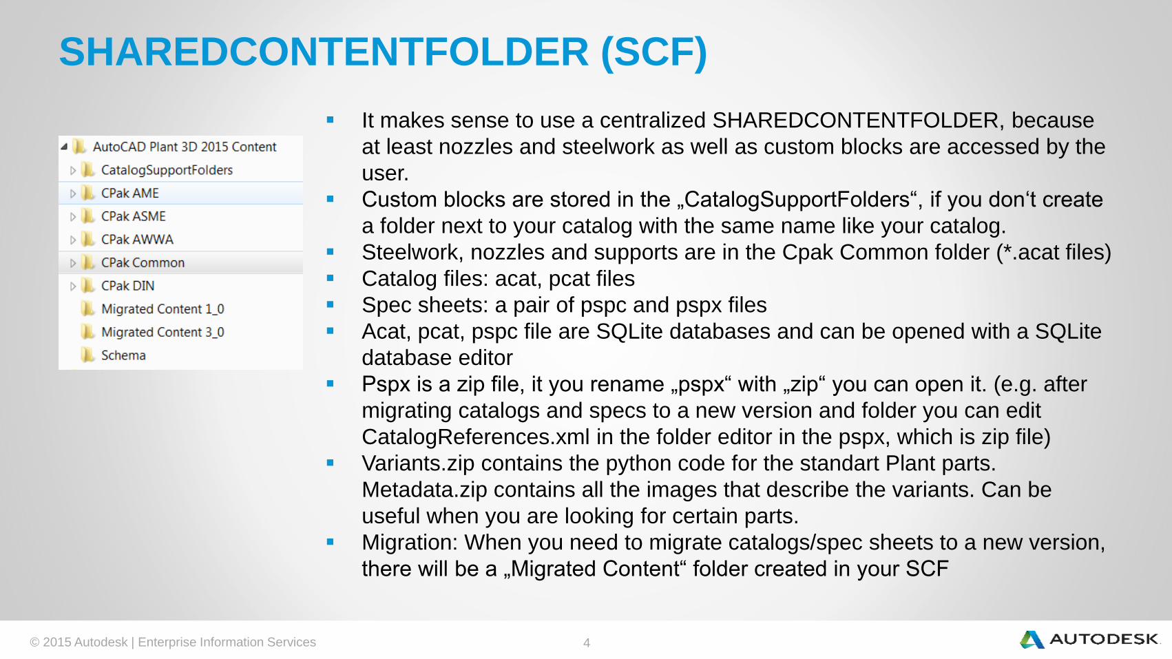
▪ It makes sense to use a centralized SHAREDCONTENTFOLDER, because
at least nozzles and steelwork as well as custom blocks are accessed by the
user.
▪ Custom blocks are stored in the „CatalogSupportFolders“, if you don‘t create
a folder next to your catalog with the same name like your catalog.
▪ Steelwork, nozzles and supports are in the Cpak Common folder (*.acat files)
▪ Catalog files: acat, pcat files
▪ Spec sheets: a pair of pspc and pspx files
▪ Acat, pcat, pspc file are SQLite databases and can be opened with a SQLite
database editor
▪ Pspx is a zip file, it you rename „pspx“ with „zip“ you can open it. (e.g. after
migrating catalogs and specs to a new version and folder you can edit
CatalogReferences.xml in the folder editor in the pspx, which is zip file)
▪ Variants.zip contains the python code for the standart Plant parts.
Metadata.zip contains all the images that describe the variants. Can be
useful when you are looking for certain parts.
▪ Migration: When you need to migrate catalogs/spec sheets to a new version,
there will be a „Migrated Content“ folder created in your SCF

© 2015 Autodesk | Enterprise Information Services 5
List of Catalog files shipped along with the product
Cpak AME:
▪ AME Ductile Iron Pipes.pcat
▪ AME Plastic Pipes.pcat
▪ AME Steel Pipes.pcat
▪ AME VALVE Imperial Catalog.pcat
▪ AME Specs
Cpak ASME:
▪ ASME Pipes and Fittings Catalog.pcat*
▪ ASME Valves Catalog.pcat**
▪ PIP & ASME Specs
Cpak AWWA:
▪ AWWA Pipes and Fittings Catalog.pcat***
▪ AWWA Spec
Cpak DIN:
▪ DIN Pipes and Fittings Catalog.pcat
▪ DIN Valves Catalog.pcat
▪ DIN Specs
Cpak Common:
▪ Structural Catalog.acat
▪ Actuator Catalog.acat
▪ NOZZLE Catalog.acat
▪ CustomParts Imperial Catalog.pcat
▪ CustomParts Metric Catalog.pcat
▪ SUPPORTS Catalog metric.acat
▪ SUPPORTS Catalog.acat
▪ Placeholder & support specs
More catalogs available on the
AutoCAD Exchange Apps Store
More to come in next version
See: http://in-the-
pipes.typepad.com/in_the_pipes/201
5/10/plant-3d-catalogs.html

© 2015 Autodesk | Enterprise Information Services 6
▪ It is strongly recommended – when creating a new catalog – to start with an existing catalog, needless parts can be deleted
later on. This will save time and avoid problems (e.g. actuators, merging catalogs troublesome).
▪ It is easier to copy existing parts and change them rather than starting from the scratch. If you want to use custom AutoCAD
blocks, then you have to make new parts or you use the catalog builder.
▪ In the file: C:\Program Files\Autodesk\AutoCAD 2014\NominalDiameterMap.csv nominal diameters can be added.
▪ Autocadplant3dcatalogbuilderconfig.xml : can be deleted to set back to default. E.g. “user defined diameter list” is saved
here
▪ In Plant 3D, command PLANTENDCODES: add endcode MPT:
▪ In order to use functions in the Catalog/Spec Editor, that require Excel, Excel has to be
installed (alternative products like Open Office wouldn’t work)
▪ Tip: all dimensioned preview pictures are contained in the file
C:\AutoCAD Plant 3D 2014 Content\Cpak Common\metadata.zip. In case you are looking
for certain parameterizations, you can quickly search the pics using the preview pictures
in the Windows Explorer.
▪ It is also possible to “export to catalog builder” a whole catalog. This will give you an
Excel file with many tabs each for one family. You can copy a certain tab to a new
Excel file and edit the parts and then import them back into the catalog. This makes
especially sense if you have to create many sizes (e.g. reducers).
▪ It is possible to work on one catalog with more than one user, because the catalog
is handled like a database.
Create new catalog, what to consider (S.1)

© 2015 Autodesk | Enterprise Information Services 7
▪ Configure encodes:
Create new catalog, what to consider (S.2)

© 2015 Autodesk | Enterprise Information Services 8
▪ PLANT MODIFY CONTENT SHARED FOLDER: This command, and the
button under Extras -> "folder modify shared content ..." do the same thing,
namely that the following dialog comes up:
Create new catalog, what to consider (S.2)
▪ It is important to know that this adjustment that can be made both in 3D and in the catalog editor, sets the Content
folder for all projects in Plant 3D.
▪ All catalogs should be in this folder (* .pcat, * .acat).
▪ This folder also graphic information are as block references in DWG files, and thumbnails for both the catalog and
for the pipe specs Viewer and for the tool palettes.

© 2015 Autodesk | Enterprise Information Services 9
(1) Catalog Editor: complement nominal width
(2) Catalog Builder: Nominal sizes supplement about Excel export
(3) Catalog Editor: create component
(4) Catalog Editor: Create a component as a copy of an existing
(5) Catalog Builder: Create components, edit geometry data and text in Excel
(6) Edit Catalog Data (texts) in Excel: Catalog Editor
(7) Catalog Editor: text, stack allocation of styles for long descriptions
(concerns: Pipe Class Data Sheets)
(8) Catalog Editor / Catalog Builder: Geometry Creation variants (Templates /
standards) / blocks / Custom Scripts
(9) Appendix SKEYs
Overview of the features of the Catalog Editor

© 2015 Autodesk | Enterprise Information Services 10
(1) Catalog Editor: add nominal diameter
• "Add nominal width":
Create a new
nominal diameter, all
fields are empty
• "Nominal diameter
duplicate": Create a
new nominal
diameter, all fields
have the values of
the copied Nominal
size (recommended)

© 2015 Autodesk | Enterprise Information Services 11
(2) Catalog Editor: add nominal diameter using Excel
Export (Seite 1)• If many sizes you want to
add, you can also work with
the Catalog Builder
• It is always the complete
catalog exported, may take
some time (eg 20 minutes)
• The export can be imported
into another catalog
(option: Two become a
catalog)
• Caution: Not all data is
exported, so lost! (e.g .:
Manufacturer).
• Not suitable for valves:
drives will be lost!
• Make sure
MatchingPipeOD is
imported, problems can
arise from the decimal
separator

© 2015 Autodesk | Enterprise Information Services 12
(2) Catalog Editor: add nominal diameter using Excel
Export (Seite 2)
• From the imported Excel
the tab that contains the
desired components copy
in a new file.
• Click on the image to view
the geometry parameter.
• Copy existing line and add
new nominal size, change
the values accordingly. (the
IDs are recalculated
duplicates do not disturb)
• Catalog Builder can now be
imported into the existing
catalog.

© 2015 Autodesk | Enterprise Information Services 13
(3) Catalog Editor: create component
• If no suitable
component in the
catalog copy is
present, you must
add a new one.
• Alternatively: (4)
Catalog Builder

© 2015 Autodesk | Enterprise Information Services 14
(4) Catalog Editor: Create a component as a copy of
an existing
• It's a component available
that meets the geometry
requirements of the new
component, then it is
easier to copy the existing
component.

© 2015 Autodesk | Enterprise Information Services 15
(5) Catalog Builder: Create components, edit
geometry data and text in Excel (S.1)
• Good for creating many
parts that are not yet or
not available in a similar,
usable geometry already
in the catalog.
• Start Catalog Builder,
then "Create a template"
- new. Enter name and
select the unit (inch or
mm).
• Continue according to the
screenshot on the right.

© 2015 Autodesk | Enterprise Information Services 16
(5) Catalog Builder: Create components, edit
geometry data and text in Excel(S.2)
1, Select Category.
Create 2.1 custom sizes
list.
Set 2.2 check and adjust
the nominal size range.
Select 3.1 or 3.2
component.
Filter 4.1 and 4.2
consecutively "1" and "2" to
define the compounds.
5. MPL is not in the list, you
have to type.
6. This is the text that
appears in the pipe spec.
7. Now save and export to
Excel, let the Catalog
Builder open.

© 2015 Autodesk | Enterprise Information Services 17
(5) Catalog Builder: Create components, edit geometry
data and text in Excel (S.3)
• Excel complete.
• Click on the small thumbnail on
the parametric representation.
• Long term size may for example
be generated by the formula.
• TYPE, SKEY not forget for
display on the isometric drawing.
• Tip: -2 as input to L21 or L22 can
(not 0 goes as input) have the
final geometry disappear
• Tip: To make the point numbers
are taken from the Excel for
MatchingPipeOD, must be used
in Excel as the point
Dezimalseperator (Advanced
Options)
• Then back to Catalogue
"Create Catalog" Generator
and click.

© 2015 Autodesk | Enterprise Information Services 18
(5) Catalog Builder: Create components, edit geometry
data and text in Excel(S.4)
• Add Recommendation to existing,
for example: C: \ AutoCAD Plant
3D 2014 Content \ CPAK
Common \ Parts Custom Metric
Catalog.pcat
• Close Catalog Builder.
• In the same folder, where the
recently added catalog is a folder
"PreviewLisps" was created, in our
case it contains a file "Elbow 90 °,
SW.lsp". This file can now be
reinziehen the Plant 3D in the
Design Area (drag & drop) to
verify all the geometry of the parts
produced.
© 2015 Autodesk | Enterprise Information Services 19
(6) Edit Catalog Data (texts) in Excel: Catalog Editor
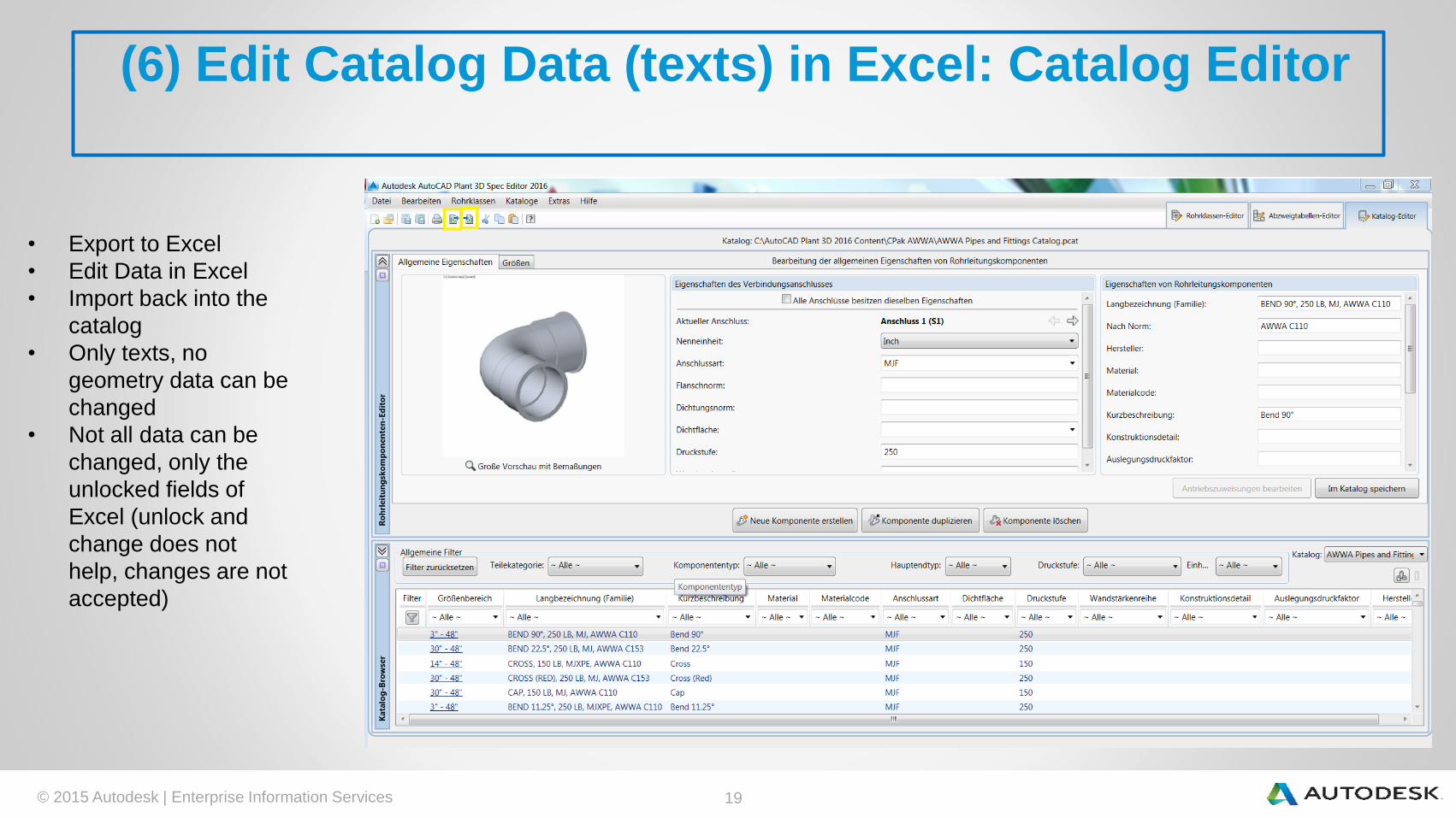
• Export to Excel
• Edit Data in Excel
• Import back into the
catalog
• Only texts, no
geometry data can be
changed
• Not all data can be
changed, only the
unlocked fields of
Excel (unlock and
change does not
help, changes are not
accepted)
© 2015 Autodesk | Enterprise Information Services 20
(7) Catalog Editor: stack allocation of styles for long
descriptions (concerns: pipe classes datasheets)
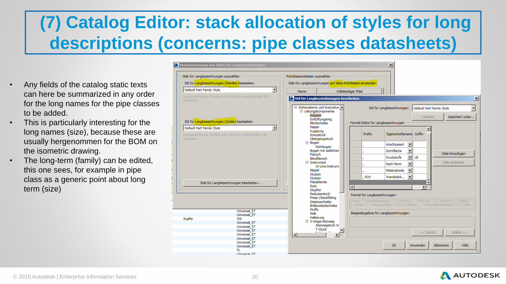
• Any fields of the catalog static texts
can here be summarized in any order
for the long names for the pipe classes
to be added.
• This is particularly interesting for the
long names (size), because these are
usually hergenommen for the BOM on
the isometric drawing.
• The long-term (family) can be edited,
this one sees, for example in pipe
class as a generic point about long
term (size)

© 2015 Autodesk | Enterprise Information Services 21
(8) Catalog Editor / Catalog Builder: Geometry Creation
variants (Templates / standards) / blocks / Custom
Scripts (S.1)• Prefabricated geometry variants we have already seen (see Catalog Builder)
• AutoCAD blocks can also be used, but must first be prepared. This is done with the command:
PLANTPARTCONVERT or in the dynamic toolbox "Custom part Add" button and then "create block-based
AutoCAD part" under "AutoCAD block" button to select and follow the instructions:
• The component has to be a AutoCAD block.
• "Adding" ENTER
• Select first connection point with your mouse to specify the direction (outward).
• You will see a blue arrow.
• ENTER to confirm.
• The same for the following points, finalize with ENTER.
• The resulting component is externally indistinguishable from a normal block, just when you enter
PLANTPARTCONVERT and the block selects, you can see the blue arrows. And then you can edit the
connection points again.
• In the component creation in the catalog or by creating through the Catalog Builder then these blocks can
be selected for each size. They are then stored in a folder that has the same name as the catalog and is
adjacent to the catalog file or – if this folder wasn’t created by the user – they will be stored in the
“CatalogSupportFolders”.

© 2015 Autodesk | Enterprise Information Services 22
(8) Catalog Editor / Catalog Builder: Geometry Creation
variants (Templates / standards) / blocks / Custom
Scripts(S.2)• The blocks can be selected by name already in the Excel file, so that the assignment when importing Excel is already taking
place:
• Actuators:
• block based valves need block based actuators
• Variant based valves can use variant based actuators
• Script based valves ? Actuator from 3d file through the properties works in 2016 (see http://in-the-
pipes.typepad.com/in_the_pipes/2015/10/mass-generation-of-actuator-blocks-for-use-on-custom-made-valves.html)
© 2015 Autodesk | Enterprise Information Services 23
(8) Catalog Editor / Catalog Builder: Geometry Creation
variants (Templates / standards) / blocks / Custom
Scripts (S.3)• There is also the option to produce components on Python programs.
• Under the following URLs are an introduction.
• http://hallmarkblogautocadpid.blogspot.ch/2013/03/python-scripting-oh-how-fun-this-is-now.html
• http://aucache.autodesk.com/au2011/sessions/4214/datasets/v1_PD4214-
L_Radhakrishnan_AnnexB_Custom%20Script%20Handout.pdf
• http://au.autodesk.com/au-online/classes-on-demand/class-catalog/2012/autocad-plant-3d/scripting-components-for-autocad-
plant-3d#
• http://adndevblog.typepad.com/.services/blog/6a0167607c2431970b0162ffdc445e970d/search?filter.q=Custom+Python+Scri
pts+for+AutoCAD+Plant+3D
• A working example with comments you can see in the next slide.
• Important commands:
• Compile with PLANTREGISTERCUSTOMSCRIPTS
• Create preview pics with PLANTSNAPSHOT
• Test with e.g. (TESTACPSCRIPT "MBTEST"), this requires to “appload” the pnp3dacpadapter.arx before
• Always restart Plant after recompiling

© 2015 Autodesk | Enterprise Information Services 24
(8) Catalog Editor / Catalog Builder: Geometry Creation
variants (Templates / standards) / blocks / Custom
Scripts (S.3)

© 2015 Autodesk | Enterprise Information Services 25
(9) More catalog related manuals, etc
▪ Add instrument to catalog (Add_an_Instrument_Family_to_a_Plant_3D_Catalog.pdf)
▪ Migrate catalog (Migrating Projects Specs and Catalogs.pdf)
▪ Bolts (Bolt Length rules.docx)
▪ Maintaining connectivity between AutoCAD Plant 3D catalogs, specs and models
http://in-the-pipes.typepad.com/in_the_pipes/2015/03/maintaining-connectivity-
between-autocad-plant-3d-catalogs-specs-and-models.html
▪ Branch Table, Warning elements:1. Open the Spec Editor Catalog:. C: \ AutoCAD Plant 3D 2016 Content \ CPAK Common \ Parts Custom Metric Catalog.pcat and select the "tea" from Duplicate this family of parts and for modifications to the long-desc
(family) and long desc (size) and a brief description in a concise phrases such as "Error element" etc.
2. Change. For all nominal widths L1, L2, L3 to 0.01 and change D1, D2, D3, for example, 5x old value
3. Add these parts in your family a pipe class.
4. Go into the branch table and place them in "Edit legend" a new element to "ERR" and assign the just created this about.
5. Assign this element all forbidden branch variants:
6. Unauthorized feeders are henceforth resulting in warning features:
▪ Adding Component Properties By Size.pdf
▪ Merge catalogs: open catalogs in one instance, mark families to copy, paste in other
catalog.

© 2015 Autodesk | Enterprise Information Services 26
appendix SKEYs (S.1)
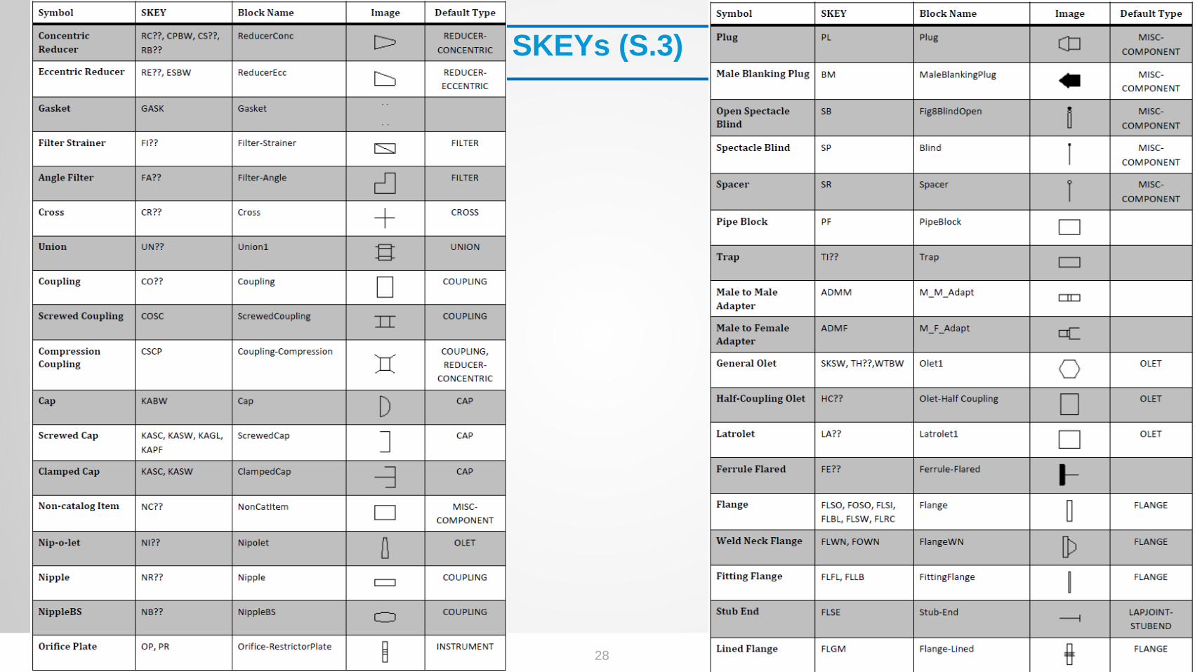
• The following is a listing of SKEYs.
• Crucially, however, which blocks are stored in the <project path> \ Isometric \ IsoSymbolStyles.dwg and how? The assignment
takes place in the <project path> \ Isometric \ IsoSkeyAcadBlockMap.xml, can be edited with the text editor. Own code can be
created and associated with their own blocks.
• The IsoSymbolStyles.dwg must be opened on the configuration ("Edit Iso icons" or similar), also blocks can be added with the
"BSAVEAS" command.

© 2015 Autodesk | Enterprise Information Services 27
SKEYs (S.2)
© 2015 Autodesk | Enterprise Information Services 28
SKEYs (S.3)

© 2015 Autodesk | Enterprise Information Services 29
SKEYs (S.4)

© 2015 Autodesk | Enterprise Information Services 30
SK
EY
s (
S.5
)