
Planning Guidelines - SMA FLEXIBLE STORAGE SYSTEM with ...
46
SI-SBS-Backup-PL-en-27 | Version 2.7 ENGLISH Planning Guidelines SMA FLEXIBLE STORAGE SYSTEM with Battery- Backup Function Circuitry Overviews, Schematic Diagrams and Material Lists
Transcript of Planning Guidelines - SMA FLEXIBLE STORAGE SYSTEM with ...

SI-SBS-Backup-PL-en-27 | Version 2.7ENGLISH
Planning GuidelinesSMA FLEXIBLE STORAGE SYSTEM with Battery-Backup FunctionCircuitry Overviews, Schematic Diagrams and Material Lists

Table of Contents SMA Solar Technology AG
Planning GuidelinesSI-SBS-Backup-PL-en-272
Table of Contents1 SMA Flexible Storage System with Battery-Backup Function .................................................. 4
1.1 Purpose of a Battery-Backup System.............................................................................................................. 41.2 Design and Function of a Battery-Backup System ......................................................................................... 4
2 Bridging Time and Self-Consumption Quota ............................................................................. 6
3 Operating Conditions of a Battery-Backup Grid ....................................................................... 83.1 Certifications and Licenses .............................................................................................................................. 83.2 Utility Grid........................................................................................................................................................ 83.3 Miniature Circuit Breaker in the Household Distribution............................................................................... 93.4 Switching Times for Loads ............................................................................................................................... 103.5 PV Inverters ...................................................................................................................................................... 10
3.5.1 Suitable PV Inverters ........................................................................................................................................ 103.5.2 Maximum AC Power of the PV Inverters ........................................................................................................ 113.5.3 Frequency-Dependent Control of Active Power at the PV Inverter................................................................ 123.5.4 Limitation of Active Power Feed-In to 0% or 0 W .......................................................................................... 12
3.6 Batteries............................................................................................................................................................ 123.6.1 Recommendations for Battery Capacity ......................................................................................................... 123.6.2 Supported Batteries.......................................................................................................................................... 133.6.3 Battery use ........................................................................................................................................................ 14
3.6.3.1 Battery Use by the Sunny Island .................................................................................................................... 143.6.3.2 Battery Use by the Sunny Boy Storage ......................................................................................................... 15
3.7 Battery inverter................................................................................................................................................. 163.7.1 Overload capacity of the battery inverters..................................................................................................... 16
3.7.1.1 Maximum Power Consumption of the Loads with Sunny Island .................................................................. 163.7.1.2 Maximum Power Consumption of all Loads with Sunny Boy Storage ........................................................ 17
3.7.2 Functions of the Sunny Boy Storage for the Battery-Backup System ............................................................ 173.8 Communication................................................................................................................................................ 18
4 Electrical Connection .................................................................................................................... 194.1 Connection of Battery-Backup Systems with Sunny Island............................................................................ 19
4.1.1 Automatic Transfer Switching Device for Single-Phase Battery-Backup System with All-PoleDisconnection ................................................................................................................................................... 19
4.1.2 Circuitry Overview for single-Phase Battery-Backup System with All-Pole Disconnection ........................... 204.1.3 Automatic Transfer Switching Device for Three-Phase Battery-Backup System with All-Pole
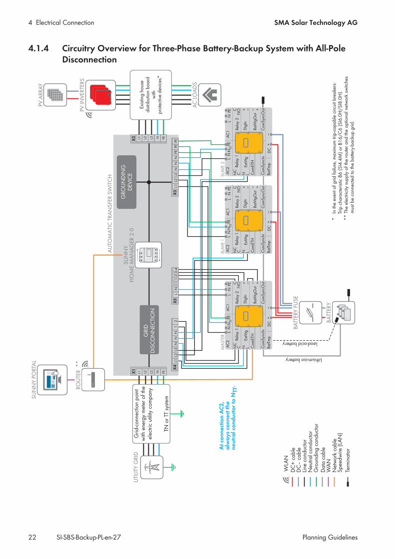
Disconnection ................................................................................................................................................... 214.1.4 Circuitry Overview for Three-Phase Battery-Backup System with All-Pole Disconnection ............................ 224.1.5 Automatic Transfer Switching Device for Single-Phase Battery-Backup System without All-Pole
Disconnection ................................................................................................................................................... 234.1.6 Circuitry Overview for Single-Phase Battery-Backup System without All-Pole Disconnection...................... 244.1.7 Automatic Transfer Switching Device for Three-Phase Battery-Backup System without All-Pole
Disconnection ................................................................................................................................................... 254.1.8 Circuitry Overview for Three-Phase Battery-Backup System without All-Pole Disconnection....................... 26
4.2 Connection of Battery-Backup Systems with Sunny Boy Storage................................................................. 274.2.1 Circuitry Overview for single-Phase Battery-Backup System with All-Pole Disconnection ........................... 274.2.2 Circuitry Overview for Single-Phase Battery-Backup System without All-Pole Disconnection...................... 28
5 Automatic Transfer Switching Device ......................................................................................... 295.1 Requirements of VDE Application Guide 2510-2 ......................................................................................... 295.2 Procurement of the Automatic Transfer Switching Device............................................................................. 295.3 Rules for the Connection of the Automatic Transfer Switching Device......................................................... 305.4 For Battery-Backup Systems with Sunny Island: Material Lists for Automatic Transfer Switching Devices. 31

Table of ContentsSMA Solar Technology AG
Planning Guidelines 3SI-SBS-Backup-PL-en-27
5.4.1 Material for Automatic Transfer Switching Device of a Single-Phase Battery-Backup System with All-Pole Disconnection........................................................................................................................................... 31
5.4.2 Material for Automatic Transfer Switching Device of a Three-Phase Battery-Backup System with All-PoleDisconnection ................................................................................................................................................... 34
5.4.3 Material for Automatic Transfer Switching Device of a Single-Phase Battery-Backup System without All-Pole Disconnection........................................................................................................................................... 37
5.4.4 Material for Automatic Transfer Switching Device of a Three-Phase Battery-Backup System without All-Pole Disconnection........................................................................................................................................... 39
5.5 Sequence of the Switching Operations in the Automatic Transfer Switching Device.................................. 415.5.1 Switching Operations in the Automatic Transfer Switching Device for Sunny Boy Storage ....................... 415.5.2 Switching Operations in the Automatic Transfer Switching Device for Sunny Island .................................. 42
6 Planning Mounting Locations...................................................................................................... 44
7 Explanation of Used Terms ......................................................................................................... 45

1 SMA Flexible Storage System with Battery-Backup Function SMA Solar Technology AG
Planning GuidelinesSI-SBS-Backup-PL-en-274
1 SMA Flexible Storage System with Battery-Backup Function1.1 Purpose of a Battery-Backup SystemAny time a grid failure happens, a PV system disconnects from the utility grid and the loads connected to the particularhousehold grid are no longer supplied with energy.A grid failure lasting for a longer period can have serious consequences for the parties concerned such as:
• Households and companies would have to manage without heat, light, telephone and computer.• Cold chains could be interrupted.• For example, if stable ventilation systems or heat lamps lose power in a farming business.
One solution for bridging this supply gap is to convert existing PV systems into battery-backup systems.An SMA Flexible Storage System with battery-backup function (battery-backup system) takes care of the uninterruptedsupply of the loads with electricity during a grid failure. An automatic transfer switching device disconnects thehousehold grid with the PV system from the utility grid. When this happens, a battery inverter forms a battery-backupgrid and the PV system can supply the loads. When the energy demand of the active loads exceeds the current powerof the PV system, the battery will provide the energy shortfall.
Information on active power limitation to 0% or 0 WIf the active power feed-in of the battery-backup system is limited to 0% or 0 W during operation, no PV energy isavailable in the event of a grid failure (see Section 3.5.4, page 12).
1.2 Design and Function of a Battery-Backup System
GRIDDISCONNECTION
UTILITY GRID
PV INVERTER
PV ARRAY
LOADS
AC Power cable
AUTOMATIC TRANSFER SWITCH
DISTRIBUTIONBOARD
GROUNDINGDEVICE
DC Power cable
BATTERY INVERTER
Figure 1: Basic design of a battery-backup system

1 SMA Flexible Storage System with Battery-Backup FunctionSMA Solar Technology AG
Planning Guidelines 5SI-SBS-Backup-PL-en-27
Devices of the SMA Flexible Storage System
Component Function
Battery inverter In the event of grid failure, the battery inverter forms a battery-backup grid and regulates theenergy distribution in this battery-backup grid. In parallel grid operation, the battery inverteris responsible for the optimization of self-consumption or internal power supply.The following battery inverters are used in battery-backup systems:
• Sunny Island 4.4M / 6.0H / 8.0H• Sunny Boy Storage 3.7 / 5.0 / 6.0
In a three-phase household grid, a single-phase battery inverter can only be connected toone line conductor and thus only monitor one line conductor for a grid failure. When the gridfailure happens, all line conductors of the household grid, however, are disconnected fromthe utility grid.
Battery (not showngraphically)
The battery stores excess energy from the PV system. In parallel grid operation, this bufferedPV energy is used to optimize self-consumption or internal power supply, and in the event ofgrid failure, it is used for supplying the loads.
Battery fuse (notshown graphically)
When using the Sunny Island with lead-acid batteries, a battery fuse must be installed. As anexternal DC fuse, the battery fuse safeguards the battery connection lines of the battery in-verter. Furthermore, the battery fuse enables DC-side disconnection of the battery inverter.Lithium-ion batteries do not usually need an external battery fuse (see manufacturer documen-tation).
Devices of the automatic transfer switching deviceThe structure of the automatic transfer switching device depends on the country-specific requirements. That is why onlythe most important components of an automatic transfer switching device are described in the following.
Component Function
Grid disconnection The functional group grid disconnection is part of the automatic transfer switch of the battery-backup system and disconnects the battery-backup grid from the utility grid in the event ofgrid failure.
Phase coupling (notshown graphically)
The phase coupling is an optional function for a single-phase battery-backup system that isconnected to a three-phase household grid.With single-phase battery-backup systems, only one battery inverter is connected to the auto-matic transfer switching device. Therefore, in the event of grid disconnection, without phasecoupling only one line conductor (e.g. L1) of the household grid is protected against grid fail-ure. In this case, the other two line conductors (e.g. L2 and L3) cannot be protected.Phase coupling enables combined switching of the line conductors in the event of grid discon-nection. As a result, the other two line conductors are also supplied with voltage. This meansthat, in the event of grid failure, a three-phase utility grid becomes a single-phase utility grid.Phase coupling can be switched on independently for the line conductors L2 und L3.
Grounding device In the case of all-pole disconnection, the functional group grounding device is part of the au-tomatic transfer switch of the battery-backup system and enables protection against indirectcontact with live components. For this, the grounding device connects the neutral conductorand the protective grounding in stand-alone mode (neutral grounding).

2 Bridging Time and Self-Consumption Quota SMA Solar Technology AG
Planning GuidelinesSI-SBS-Backup-PL-en-276
2 Bridging Time and Self-Consumption QuotaThis section describes a method by which you can estimate bridging time and self-consumption quota for anSMA Flexible Storage System with battery-backup function. For the battery capacity, an empirical value of a typicalbattery-backup system is assumed and verified by means of the estimate. In the example, the assumed values for theenergy demand of the loads in a private household, the peak power of the PV system and the battery capacity arecharacteristic of a battery-backup system in a four-person single-family household in Germany.
Step 1: Estimation of self-consumption quota for an SMA Flexible Storage System
Input data (example):• Peak power of the PV system: 5000 Wp• Annual energy demand: 5000 kWh• Total battery capacity: 10000 Wh, of which the Sunny Island uses 50% for intermediate storage of PV energy.
The usable battery capacity therefore amounts to 5000 Wh.
= 1 Wp/kWh5,000 Wp
5,000 kWh=
Peak power
Annual energy requirement
= 1 Wh/kWhUsable battery capacity
Annual energy demand
5000 Wh
5000 kWh=
Transfer the calculated values to the diagram to estimate the self-consumption quota.
90% 80% 70% 60%
50%
40%
1.6
2.0
1.4
1.2
1.0
0.6
0.4
0.2
0
0.8
1.8
2.01.51.00.50.25
Peak power of the PV system / Annual energy requirement [Wp/kWh]
Usa
ble
ba
ttery
ca
pa
city
/ A
nnua
l ene
rgy
dem
and
[Wh/
kWh]
Figure 2: Estimation of the self-consumption quota with intermediate storage
The estimate reveals that the self-consumption quota, with energy management with intermediate storage, isapproximately 60%.
Step 2: Estimation of energy demand in the event of grid failure
Input value:• Annual energy demand: 5000 kWh
= 13.6/kWh5000 kWh
365 days=
365 days
Annual energy requirement

2 Bridging Time and Self-Consumption QuotaSMA Solar Technology AG
Planning Guidelines 7SI-SBS-Backup-PL-en-27
It can be assumed that during a grid failure, electrical energy will be used sparingly, e.g. by switching off energy-intensive loads. As a result, the daily energy demand of 13.6 kWh can be reduced. In this case, at a reduction by40%, the energy demand of this household will be around 8 kWh in the event of a 24-hour grid failure.
Step 3: Estimation of PV generation during a grid failureThe peak power of the PV system is at 5000 Wp. In Germany in the winter, it can be assumed that 0.7 kWh/kWp willbe generated. Hence, an energy yield from PV production of 3.5 kWh between sunrise and sunset is derived.
Step 4: Calculation of battery capacity required for the battery-backup function
Input value:• Daily energy demand of the household: 8 kWh• Daily energy yield from PV production: 3.5 kWh
Battery capacity = Energy demand − PV generation = 8 kWh − 3.5 kWh = 4.5 kWh
The required battery capacity amounts to 4.5 kWh. In Step 1, a battery capacity of 10 kWh was assumed. Thus, inthis example 45% of the battery capacity will be needed as energy reserve for grid failure on a winter day.
ResultWith lead-acid batteries, the default value of 45% of a Sunny Island parameter battery capacity is reserved for thebattery-backup function in winter operation. This value is within the value range of 15% to 60% in which the batterycapacity must range (see Section 3.6.3.1, page 14). Thus, the battery used for the SMA Flexible Storage System isalso adequate for the battery-backup function.

3 Operating Conditions of a Battery-Backup Grid SMA Solar Technology AG
Planning GuidelinesSI-SBS-Backup-PL-en-278
3 Operating Conditions of a Battery-Backup Grid3.1 Certifications and LicensesIn which countries the battery-backup system may be used depends primarily on the licenses and certifications of thebattery inverter. Coordinate with the grid operator which certification must be provided for operation (information oncertifying the battery inverter see www.SMS-Solar.com).Another thing to take into account when selecting the operation site is the availability of automatic transfer boxes ineach country (see Section 5.2, page 29).
3.2 Utility GridOnly utility grid permitted as external energy sourceThe only permitted external energy source in the battery-backup grid is the utility grid. Even when using theSunny Island, the battery-backup system does not support the operation with a generator (e.g. diesel generator).
Residual-current monitoring unit:If an external residual-current device is required, install a residual-current device which trips at a residual current of100 mA or higher (for details on selecting a residual-current device, see the Technical Information "Criteria forSelecting a Residual-Current Device" at www.SMA-Solar.com).
Special conditions for use of the battery-backup grid with Sunny Island in BelgiumThe utility grid connected to the automatic transfer switching device must generally be a TN or TT system. InBelgium, the utility grid can be designed to function as an IT system that is, however, grounded to the neutral pointof the source.This results in a hybrid form of an IT and TT system. Compared with a TT system, this hybrid form is not equippedwith a neutral conductor. With this installation, the following restriction applies when using the battery-backupsystem:
• If the utility grid functions as an IT system that is grounded to the neutral point of the source, the connectedbattery-backup system must be single-phase.
Characteristics of the battery-backup grid
Characteristic Single-phase battery-backup grid withSunny Island or Sunny Boy Storage
Three-phase battery-backup grid withSunny Island
Utility grid TN or TT system
Single-phase or three-phase Three-phase
Behavior of the battery in-verters in the event of gridfailure
One Sunny Island or one Sunny Boy Stor-age supplies the battery-backup grid.
Three Sunny Island inverters switched inparallel on the DC side supply each lineconductor with the corresponding phase.
Recognition of grid failure Grid failure is only recognized on the lineconductor which is connected to the bat-tery inverter (e.g. L1).
Grid failure is recognized on all line con-ductors.
Supply of the loads in theevent of grid failure
Only some of the loads are supplied (e.g.the loads connected to L1).
All loads are supplied.
Grid feed-in by the PV in-verters in the event of gridfailure
Only single-phase PV inverters can feed en-ergy into the grid.
Single-phase and three-phase PV inverterscan feed energy into the grid.

3 Operating Conditions of a Battery-Backup GridSMA Solar Technology AG
Planning Guidelines 9SI-SBS-Backup-PL-en-27
Characteristic Single-phase battery-backup grid withSunny Island or Sunny Boy Storage
Three-phase battery-backup grid withSunny Island
Phase coupling in the bat-tery-backup grid
Phase coupling is possible. Phase coupling is not possible.
Rotating magnetic field inthe battery-backup grid
No: even with phase coupling, the battery-backup grid remains single-phase.
Yes: three Sunny Island inverters form athree-phase battery backup grid with rotat-ing magnetic field.
Phase couplingIf three-phase loads are connected to a single-phase utility grid with phase coupling, SMA Solar Technology AGcannot rule out damage to the three-phase loads. With phase coupling, single-phase loads only must be connected tothe battery-backup grid.
Battery-backup grid with or without all-pole disconnection
Type of grid disconnec-tion
All-pole disconnection Non-all-pole disconnection
Operating principle In the event of grid failure, a tie switch dis-connects all line conductors and the neu-tral conductor from the utility grid.
In the event of grid failure, a tie switch dis-connects all line conductors from the utilitygrid. The neutral conductor of the battery-backup grid remains permanently con-nected to the utility grid.
Criterion for use If the technical connection requirements ofthe grid operator or the locally applicablestandards and directives call for all-poledisconnection, you must install the battery-backup system with all-pole disconnection.
If the technical connection requirements ofthe grid operator or the locally applicablestandards and directives prohibit discon-nection of the neutral conductor, you mustinstall the battery-backup system withoutall-pole disconnection.
3.3 Miniature Circuit Breaker in the Household DistributionIn the event of a grid failure, the battery inverter creates a battery-backup grid (TN-S grid configuration). Therefore,only the battery inverter can trip circuit breakers and residual-current devices in the household distribution in case of agrid failure. The residual-current device in the automatic transfer switching device is not able to do that. It only protectsthe battery inverter in parallel grid operation.The circuit breakers in the household distribution must therefore comply with the maximum tripping characteristics listedfor the battery inverter.
Sunny Island
Device type Maximum tripping characteristics
SI4.4M-12 / SI4.4M-13 (Sunny Island 4.4M) B6 (B6A)
SI6.0H-12 / SI6.0H-13 (Sunny Island 6.0H) B16 (B16A)
SI8.0H-12 / SI6.0H-13 (Sunny Island 8.0H) B16 (B16A)
If circuit breakers are installed up to the mentioned tripping characteristic, the battery inverter is able to fulfill therequired automatic disconnection of supply with the respective disconnection times in accordance with VDE 0100-410.If a circuit breaker has a higher tripping characteristic, an additional residual-current device of type A must be installedin the loads distribution. In doing so, an already existing residual-current device of type A can also be used.

3 Operating Conditions of a Battery-Backup Grid SMA Solar Technology AG
Planning GuidelinesSI-SBS-Backup-PL-en-2710
Sunny Boy Storage
Device type Maximum tripping characteristics
SBS3.7-10 (Sunny Boy Storage 3.7) B6 (B6A)
SBS5.0-10 (Sunny Boy Storage 5.0) B6 (B6A)
SBS6.0-10 (Sunny Boy Storage 6.0) B16 (B16A)
If a miniature circuit breaker has a higher trip characteristic, the Sunny Boy Storage does not switch off the miniaturecircuit breaker in the event of a fault.
3.4 Switching Times for LoadsThe SMA Flexible Storage System with battery-backup function does not fulfill the requirements of an uninterruptiblepower supply as per IEC 62040. In the event of grid failure, an automatic transfer switching device disconnects thebattery-backup grid from the utility grid. After disconnection, the loads and the PV system are not supplied forapproximately five to seven seconds, until the battery-backup system can provide active power and reactive poweragain.If any single load (e.g. a computer) requires an uninterruptible power supply in compliance with the standard or aswitching time shorter than five to seven seconds, this load will need a separate uninterruptible power supply inaccordance with IEC 62040.
Longer switching periods for phase couplingLoads integrated in the battery-backup grid via phase coupling have a higher switching time, as theSMA Flexible Storage System with battery-backup function connects phase coupling with a time delay.
• Maximum switching time for Sunny Island: 15 seconds• Maximum switching time for Sunny Boy Storage: 10 seconds
3.5 PV Inverters
3.5.1 Suitable PV InvertersNo three-phase PV inverters in single-phase battery-backup systemsIn the event of grid failure, only single-phase PV inverters can feed their output power into a single-phase battery-backup grid. Three-phase PV inverters cannot feed into the single-phase battery-backup grid. Thus, three-phase PVinverters are not recommended for single-phase battery-backup systems. Possible solutions are:
• Replace the three-phase PV inverter by a combination of single-phase PV inverters, e.g. two Sunny Boy 4.0inverters instead of one Sunny Tripower 8000TL.
• Select a sufficiently large battery capacity to ensure the supply of the loads from the battery only over theentire bridging time.
For a SMA Flexible Storage System with battery-backup function, only PV inverters are suitable that can limit the activepower depending on frequency (for information on frequency-dependent active power limitation see the Technicalinformation "SMA GRID GUARD 10.0 - Grid management services through SMA Inverter"). In the following PVinverters you can activate frequency-dependent active power limitation as of the indicated firmware version.
PV inverter Firmware version*
Sunny Boy (SB)
SB1.5-1VL-40 / SB2.5-1VL-40 1.01.07.R
SB2.0-1VL-40 02.05.01.R
SB3.0-1AV-40 / SB3.6-1AV-40 / SB4.0-1AV-40 / SB5.0-1AV-40 01.02.18.R

3 Operating Conditions of a Battery-Backup GridSMA Solar Technology AG
Planning Guidelines 11SI-SBS-Backup-PL-en-27
PV inverter Firmware version*
SB3.0-1AV-41 / SB3.6-1AV-41/ SB4.0-1AV-41 / SB5.0-1AV-41 / SB6.0-1AV-41 for use inGermanySB3.0-1AV-41 / SB3.6-1AV-41/ SB4.0-1AV-41 / SB5.0-1AV-41 / SB6.0-1AV-41 for useoutside Germany
1.01.31.R1.01.32.R
SB 1300TL-10 / 1600TL-10 / 2100TL-10 4.52
SB 2500TLST-21 / 3000TLST-21 2.50.41.R
SB 3300-11 4.03
SB 3800-11 4.02
SB 2000HF-30 / 2500HF-30 / 3000HF-30 2.30.07.R
SB 3000TL-21 / 3600TL-21 / 4000TL-21 / 5000TL-21 2.51.02.R
Sunny Tripower (STP)
STP 5000TL-20 / 6000TL-20 / 7000TL-20 / 8000TL-20 / 9000TL-20 / 10000TL-20 /120000TL-20
2.50.01.R
STP 8000TL-10 / 10000TL-10 / 12000TL-10 / 15000TL-10 / 17000TL-10 2.51.02.R
STP 15000TL-30 / 20000TL-30 / 25000TL-30 2.82.03.R
STP 15000TLEE-10 / 20000TLEE-10 2.54.03.R
STP3.0-3AV-40 / STP4.0-3AV-40 / STP5.0-3AV-40 / STP6.0-3AV-40 2.13.07.R
STP8.0-3AV-40 / STP10.0-3AV-40 1.01.18.R
* With older firmware versions, a firmware update is required (see manual of the PV inverter).
3.5.2 Maximum AC Power of the PV InvertersThe AC power that the PV inverters are permitted to feed into the battery-backup system is limited mainly by the ratedpower of the battery inverter.
Type of battery-backup system
Device type Battery in-verter*
PV inverter**
Single-phase system withSunny Island
SI4.4M-12 / SI6.0H-13 (Sunny Island 4.4M) 3.3 kW 4.6 kW
SI6.0H-12 / SI6.0H-13 (Sunny Island 6.0H) 4.6 kW 9.2 kW
SI8.0H-12 / SI8.0H-13 (Sunny Island 8.0H) 6.0 kW 12 kW
Single-phase system withone Sunny Boy Storage
SBS3.7-10 (Sunny Boy Storage 3.7) 3.68 kW 4.9 kW
SBS5.0-10 (Sunny Boy Storage 5.0) 5.00 kW 6.7 kW
SBS6.0-10 (Sunny Boy Storage 6.0) 6.00 kW 7.7 kW

3 Operating Conditions of a Battery-Backup Grid SMA Solar Technology AG
Planning GuidelinesSI-SBS-Backup-PL-en-2712
Type of battery-backup system
Device type Battery in-verter*
PV inverter**
Three-phase system withone Sunny Island
SI4.4M-12 / SI6.0H-13 (Sunny Island 4.4M) 9.9 kW 13.8 kW
SI6.0H-12 / SI6.0H-13 (Sunny Island 6.0H) 13.8 kW 27.6 kW
SI8.0H-12 / SI8.0H-13 (Sunny Island 8.0H) 18.0 kW 36 kW
* Rated power of the battery inverter** Maximum AC power of the PV inverters
When estimating the maximum AC power of the PV inverters, the following factors can also be considered:• The yield of the PV power is influenced by the solar irradiation on site. As a result, the AC power output of the the
PV inverters can be reduced.• Local regulations can call for permanent limitation of active power feed-in to a fixed amount or a percentage
share of the installed nominal PV system power. This can also lower the AC power output of the PV inverters.
3.5.3 Frequency-Dependent Control of Active Power at the PV InverterIf PV inverters are to be used in an SMA Flexible Storage System with battery-backup function, they must limit theiractive power as a function of frequency. The manner of the frequency-dependent active power limitation complies withthe locally applicable standards and directives (for further information see Technical information "SMA GRID GUARD10.0 - Grid management services through SMA Inverter").
3.5.4 Limitation of Active Power Feed-In to 0% or 0 WSome grid operators permit connection of PV systems only on condition that no active power is fed into the utility grid.To fulfill this requirement, the Sunny Home Manager is able to limit the active power feed-in to 0% or 0 W (zeroexport).If the active power feed-in of the battery-backup system incl. Sunny Home Manager is limited to 0% or 0 W duringoperation, no PV energy is available in the event of a grid failure. The battery-backup system is only supplied withenergy from the battery.An upcoming firmware update of the Sunny Home Manager will enable PV energy to be used even if the active powerfeed-in is limited to 0% or 0 W in the event of a grid failure.
3.6 Batteries
3.6.1 Recommendations for Battery CapacitySMA Solar Technology AG recommends the following minimum battery capacities when using the Sunny Island. Therecommended battery capacities must be observed to ensure stable operation of the system.
Battery-backup system Battery capacity for a ten-hour electric discharge(C10)
Single-phase battery-backup system with SI4.4M-12 / SI4.4M-13 (Sunny Island4.4M)
100 Ah
Single-phase battery-backup system with SI6.0H-12 / SI6.0H-13 (Sunny Island6.0H)
120 Ah
Single-phase battery-backup system with SI8.0H-12 / SI8.0H-13 (Sunny Island8.0H)
160 Ah
Three-phase battery-backup system with three SI4.4M-12 / SI4.4M-13 (Sunny Is-land 4.4M)
300 Ah

3 Operating Conditions of a Battery-Backup GridSMA Solar Technology AG
Planning Guidelines 13SI-SBS-Backup-PL-en-27
Battery-backup system Battery capacity for a ten-hour electric discharge(C10)
Three-phase battery-backup system with three SI6.0H-12 / S16.0H-13 (Sunny Island6.0H)
360 Ah
Three-phase battery-backup system with three SI8.0H-12 / SI8.0H-13 (Sunny Island8.0H)
480 Ah
Single-phase battery-backup system with SBS3.7-10 (Sunny Boy Storage 3.7) see Technical Information"Approved batteries and bat-tery communication connec-tion"
Single-phase battery-backup system with SBS5.0-10 (Sunny Boy Storage 5.0)
Single-phase battery-backup system with SBS6.0-10 (Sunny Boy Storage 6.0)
3.6.2 Supported Batteries
Sunny IslandThe Sunny Island supports lead-acid batteries of types FLA and VRLA as well as various lithium-ion batteries. It isimportant to observe the capacity:
• Lead-acid batteries with a capacity of 100 Ah to 10000 Ah can be connected.• Lithium-ion batteries with a capacity of 50 Ah to 10000 Ah can be connected.
This corresponds to a maximum storage capacity of 480 kWh for a battery with 48 V and 10000 Ah.A lithium-ion battery is especially suited for intermediate storage of PV energy due to its high cycle stability. The lithium-ion batteries must be compatible with the Sunny Island:
• The battery must comply with the locally applicable standards and directives and must be intrinsically safe.• The Sunny Island must only be operated in connection with an intrinsically safe lithium-ion battery approved by
SMA Solar Technology AG (see Technical Information “List of Approved Batteries” at www.SMA-Solar.com).• If no lithium-ion battery approved for the Sunny Island can be used, use a lead-acid battery.
Sunny Boy StorageThe Sunny Boy Storage must only be operated in connection with an intrinsically safe lithium-ion battery approved bySMA Solar Technology AG (see Technical Information "Approved batteries and battery communication connection" atwww.SMA-Solar.com).
Lithium-ion battery for Sunny Island and Sunny Boy StorageThe battery management of lithium-ion batteries controls the operation of the battery. To enable battery management,the lithium-ion battery must be connected to the battery inverter via a data cable.In the case of compatible lithium-ion batteries, SMA Solar Technology AG has only tested the interaction between thebattery inverter and the battery management of the lithium-ion battery. For information on other technical properties ofthe batteries, please contact the respective manufacturer of the lithium-ion battery.
Lithium-ion batteries in battery-backup systemsIn order to meet the requirements of battery-backup systems in the event of grid failure, the battery inverter has anoverload capacity. To be able to use this overload capacity, the output powers and output currents of the batteryinverter must be taken into consideration when selecting the battery (for Sunny Island see Technical information“List of Approved Batteries”, for Sunny Boy Storage see Technical information "Approved batteries and batterycommunication connection").

3 Operating Conditions of a Battery-Backup Grid SMA Solar Technology AG
Planning GuidelinesSI-SBS-Backup-PL-en-2714
3.6.3 Battery use
3.6.3.1 Battery Use by the Sunny IslandIn many regions, the PV energy available largely depends on the season and the hours of sunshine. The dischargebehavior can be adjusted to the location and time by the Sunny Island.
t
SOC
0 %
100 %
A
B
C
D
E
Winter Summer Winter
Figure 3: Ranges of the battery state of charge as a function of the season for the northern hemisphere (example)
Position Range Explanation
A Self-consumption area (SlfCsmp) Range for intermediate storage
B State of charge conservation area(PVRes)
Range for maintenance of the battery state ofcharge
C Backup power area (BURes) Range for battery-backup function
D Deep discharge protection area (BatRes) Range for protection against deep discharge
E Deep discharge area (ProtRes) Range for protection in the event of deep discharge
Due to the seasonal battery operation of the Sunny Island, a larger range is reserved for the battery backup function inwinter than in summer. This makes sense, as consumption in summer is lower and the PV yield is also much higher insummer. The limits for the ranges of battery state of charge are predetermined for lead-acid batteries and lithium-ionbatteries by the following value ranges of the Sunny Island inverter.
Range Lead-acid battery Lithium-ion battery
Shortest day* Longest day** Shortest day* Longest day**
Self-consumptionarea
65% to 100% 45% to 100% 30% to 100% 28% to 100%
State of chargeconservation area
60% to 65% 40% to 45% 25% to 30% 23% to 28%

3 Operating Conditions of a Battery-Backup GridSMA Solar Technology AG
Planning Guidelines 15SI-SBS-Backup-PL-en-27
Range Lead-acid battery Lithium-ion battery
Shortest day* Longest day** Shortest day* Longest day**
Backup powerarea
15% to 60% 15% to 40% 13% to 25% 13% to 23%
Deep dischargeprotection area
10% to 15% 10% to 15% 3% to 13% 3% to 13%
Deep dischargearea
0% to 10% 0% to 10% 0% to 3% 0% to 3%
* December 21 (northern hemisphere) or June 21 (southern hemisphere)** June 21 (northern hemisphere) or December 21 (southern hemisphere)
The value ranges for lithium-ion batteries reserve a smaller proportion of battery capacity for the battery-backupfunction: 10% of battery capacity in summer and 12% of battery capacity in winter. Therefore, the proportionavailable for intermediate storage is correspondingly larger.
3.6.3.2 Battery Use by the Sunny Boy Storage
Range Parameter (technical term) Battery inverter behavior
A Self-consumption range (SlfCsmp) The battery inverter uses the batteries within thisrange for increased self-consumption and for the"Time-of-Use" and "Peak Load Shaving" functionsthat can be configured in the power profile.
C Minimum width of backup power range (BURes) Range for battery-backup operation during gridfailure This range is set to 0% by default. If an auto-matic transfer switching device is connected, therange must be set depending on your needs. Thesetting value refers to the user SOC.Utility grid available:When the upper limit of C is reached, the batteryinverter goes into standby mode. The batteries re-main switched on. Excess PV energy is used forconserving the battery charge.When the SOC in range C has decreased by theset value of range B, the battery inverter rechargesthe batteries with 3 A from the utility grid.If the set value of the parameter for range B is lessthan the set value of the parameter for range C, thebatteries are recharged in range D first.

3 Operating Conditions of a Battery-Backup Grid SMA Solar Technology AG
Planning GuidelinesSI-SBS-Backup-PL-en-2716
Range Parameter (technical term) Battery inverter behavior
B Range for maintaining battery state of charge(PVRes)
Utility grid available:The battery inverter checks the current SOC every24 hours. If the SOC is in range D, the batteriesare recharged with 3 A from the utility grid until theupper limit of range C is reached.During battery-backup operation:The battery inverter starts up every two hours forapprox. six minutes and attempts to charge the bat-teries with PV energy. If no excess PV energy isavailable, the battery inverter switches to standbymode.
D Minimum width of deep-discharge protection range(BatRes)
Once the limit from B to D is reached, the batteryand battery inverter switch off. The battery-backupoperation can be enabled by switching on theblack-start switch of the battery inverter. If the bat-tery is not recharged after six minutes, the battery-backup operation will be stopped. No automaticstart-up process will be initiated after two hours.When range D is reached and the utility grid isavailable, the battery inverter charges the batterieswith 3 A from the utility grid.
E Lower limit of the deep-discharge protection rangefor disconnection (ProtRes)
If range E is reached during battery-backup opera-tion, the batteries are switched off. The battery in-verter is also switched off due to a lack of DC volt-age.When range E is reached and the utility grid isavailable, the battery inverter charges the batterieswith 3 A from the utility grid until range A isreached.
3.7 Battery inverter
3.7.1 Overload capacity of the battery inverters
3.7.1.1 Maximum Power Consumption of the Loads with Sunny IslandThe maximum power consumption of the loads during the day and the type of battery-backup system determine thedevice type and the number of battery inverters. In a single-phase battery backup system with Sunny Island, forinstance, the maximum power consumption of the loads must be less than the maximum power of the Sunny Island fora duration of 30 min at 25°C.
Type of battery-backup system
Maximumpower*
Device type Number of invert-ers
Single-phase 4.4 kW SI4.4M-12 / SI4.4M-13 (Sunny Island 4.4M) 1
6 kW SI6.0H-12 / SI6.0H-13 (Sunny Island 6.0H)
8 kW SI8.0H-12 / SI8.0H-13 (Sunny Island 8.0H)

3 Operating Conditions of a Battery-Backup GridSMA Solar Technology AG
Planning Guidelines 17SI-SBS-Backup-PL-en-27
Type of battery-backup system
Maximumpower*
Device type Number of invert-ers
Three-phase 13.2 kW SI4.4M-12 / SI4.4M-13 (Sunny Island 4.4M) 3
18 kW SI6.0H-12 / SI6.0H-13 (Sunny Island 6.0H)
24 kW SI8.0H-12 / SI8.0H-13 (Sunny Island 8.0H)
* Maximum power of the battery inverter inverter for 30 minutes at 25°C and 230 V
Short-term overload during grid failureShort-term overload peaks of the loads can be compensated by the battery inverter within its technical power limits(see operating manual of the inverter inverter at www.SMA-Solar.com). However, the DC cabling from the batteryinverter to the battery must be designed to withstand this overload operation.
3.7.1.2 Maximum Power Consumption of all Loads with Sunny Boy StorageThe maximum power consumption of the loads during the day and the type of battery-backup system determine thedevice type and the number of battery inverters. In a single-phase battery backup system with Sunny Boy Storage, themaximum power consumption of the loads must be less than the maximum power of the Sunny Boy Storage for aduration of 1 min at 25°C.
Type of battery-backup system
Maximum power of the inverterfor one minute at 25°C and230 V
Device type Number of in-verters
Single-phase 4.6 kW SBS3.7-10 (Sunny Boy Storage 3.7)
1
6.4 kW SBS5.0-10 (Sunny Boy Storage 5.0)
7.5 kW SBS6.0-10 (Sunny Boy Storage 6.0)
3.7.2 Functions of the Sunny Boy Storage for the Battery-Backup System
Black start functionThe inverter has a black start function and an auxiliary battery that provides energy for the black start. In battery-backup systems, you have the possibility to install a standard switch for black starting the inverter and battery. Theblack-start switch is used to start the battery-backup operation manually in the event of grid failure if the battery andinverter are in sleep mode and, therefore, are unable to provide energy. When the black-start switch is switched onmanually, the energy from the auxiliary battery is made available in order to automatically switch the battery andtherefore also the inverter from sleep mode to operation in order that the inverter can make energy available from thebattery. You can stop the battery-backup operation by switching it off manually. To enable the black-start function, atleast one battery capable of black start must be connected to input A.
Battery-backup operation with empty batteryWhen the battery is fully discharged during a grid failure, the battery inverter cannot initially provide any AC voltage.If there is sufficiently high PV power, the PV inverter charges the battery until a preset state of charge has been reached(usually 5%). If there is no PV power available, the start-up is canceled and no more AC voltage is provided. Thebattery inverter attempt starting up again when a defined waiting time has expired or a black start has beenrequested.

3 Operating Conditions of a Battery-Backup Grid SMA Solar Technology AG
Planning GuidelinesSI-SBS-Backup-PL-en-2718
After five attempts, the battery inverter terminates the start-up and switches to sleep mode. The battery inverter can thenonly be started manually using the black start switch.
3.8 CommunicationElectricity supply of communication devicesDuring a grid failure, only the devices in the battery-backup grid are supplied with current. If the router, the optionalswitch or other communication devices are not supplied with electricity, many of the inverters' capabilities in thebattery-backup system are limited or unavailable.
• Connect the electricity supply of the router and the optional network switches to the battery-backup grid.
Requirements for the Speedwire networkThe battery inverter and the Sunny Home Manager 2.0 can be directly interconnected via Speedwire. If more than twodevices are to communicate via Speedwire or the Sunny Home Manager 2.0 is to establish an internet connection tothe Sunny Portal, a Speedwire network is required.
Requirements:☐ All Speedwire devices must be connected to the same router.☐ The router and the optional network switch must fully support Multicast.☐ The router must support "Internet Enabled Devices" with the SIP and STUN interfaces.
Most common routers and network switches support Multicast and "Internet Enabled Devices".

4 Electrical ConnectionSMA Solar Technology AG
Planning Guidelines 19SI-SBS-Backup-PL-en-27
4 Electrical Connection4.1 Connection of Battery-Backup Systems with Sunny Island
4.1.1 Automatic Transfer Switching Device for Single-Phase Battery-BackupSystem with All-Pole Disconnection
F6(C
32
A)
Q3
Q2
Q4
Q4
Q3
Q3
Q4Q6
F53
*
F3
X3
L1N
PE
Q4
Q4
Q3
Q3 Q
2
3F1
*
X5
L1N
12
34
F4(C
32A
)
2*
SU
NN
Y H
OM
EM
AN
AG
ER 2
.0
(C32
A)
L1N
12
X4
X2 PENL3L2L1
X1
PENL3L2L1
Pha
se c
oup
ling
for
sing
le-p
hase
op
era
tion
Grid
dis
conn
ectio
n
op
tiona
l
Gro
und
ing
dev
ice
1F2
*(4
0A
/0,0
3A
Typ
e A
)
F7(4
0A
/0,0
3A
Typ
e A
)
1*
Onl
y w
hen
conn
ectin
g to
a T
T g
rid, t
he li
ne c
ond
ucto
r a
nd th
e ne
utra
l co
nduc
tor
mus
t be
fuse
d.
2*
No
t req
uire
d fo
r sy
stem
s w
itho
ut in
crea
sed
sel
f-co
nsum
ptio
n.3
* R
equi
rem
ents
for
ther
ma
l fus
e us
ed: 1
A, n
om
ina
l co
ld r
esis
tanc
e o
f at l
east
0.2
Ω a
nd m
eltin
g in
teg
ral m
ax.
1A
2s.
The
ind
ica
ted
va
lues
in b
rack
ets
are
rec
om
men
ded
by
SM
A S
ola
r Te
chno
log
y A
G. T
he e
lect
rica
l dev
ices
mus
t be
des
igne
d in
acc
ord
anc
e w
ith th
e lo
cally
ap
plic
ab
le s
tand
ard
s a
nd d
irect
ives
.

4 Electrical Connection SMA Solar Technology AG
Planning GuidelinesSI-SBS-Backup-PL-en-2720
4.1.2 Circuitry Overview for single-Phase Battery-Backup System with All-PoleDisconnection
PENL3L2L1X1
PENL3L2L1X2
12
X4
L1N
X3
L1N
PE
PE
X5
LN
12
34
Ba
tTm
p+
_D
C
NA
C2
Co
mET
H
Co
mS
yncO
utC
om
Syn
cIn
LA
C1
NN
TTPE
LNCNC
LPE
Ba
tVtg
Out
Rela
y 1
Rela
y 2
Dig
InEx
tVtg
+ _ _
NOC +
SU
NN
Y P
ORT
AL
WLA
N
Lithium-ion battery
Lead-acid battery
BA
TTER
Y
PV IN
VER
TERS
PV A
RRA
Y
At
con
ne
ctio
n A
C2
, a
lwa
ys
con
ne
ct t
he
ne
utr
al c
on
du
cto
r to
NTT
.
WA
N
Gro
und
ing
co
nduc
tor
Da
ta c
ab
le
Line
co
nduc
tor
Neu
tral c
ond
ucto
r
DC
+ c
ab
leD
C–
ca
ble
Term
ina
tor
Net
wo
rk c
ab
le
Sp
eed
wire
(LA
N)
UTI
LITY
GRI
DG
rid-c
onn
ectio
n p
oin
tw
ith e
nerg
y m
eter
of t
heel
ectr
ic u
tility
co
mp
any
TN o
r TT
sys
tem
AU
TOM
ATI
C T
RAN
SFE
R SW
ITC
H
op
tiona
l
PHA
SE
CO
UPL
ING
GRI
DD
ISC
ON
NEC
TIO
N
Exis
ting
ho
use
dis
trib
utio
n b
oa
rdw
ithp
rote
ctiv
e d
evic
es*
GRO
UN
DIN
GD
EVIC
E
**
The
ele
ctric
ity s
upp
ly o
f the
ro
uter
and
the
op
tiona
l net
wo
rk s
witc
hes
mus
t be
conn
ecte
d to
the
ba
ttery
-ba
ckup
grid
.
*
In th
e ev
ent o
f grid
failu
re, m
axi
mum
trip
-ca
pa
ble
circ
uit b
rea
kers
:
Trip
cha
ract
eris
tic B
6 (
SI4
.4M
) o
r B
16
/C6
(S
I6.0
H/S
I8.0
H).
BA
TTER
Y F
US
E
ROU
TER
**
SU
NN
Y H
OM
EM
AN
AG
ER 2
.0

4 Electrical ConnectionSMA Solar Technology AG
Planning Guidelines 21SI-SBS-Backup-PL-en-27
4.1.3 Automatic Transfer Switching Device for Three-Phase Battery-BackupSystem with All-Pole Disconnection
Q2
X1
Q3
Q2
Q4
F53
*
F6(C
32
A)
Q4
Q4
Q3
Q3
Q4
Q4
Q3
Q3
X3
L1L2
L3N
NN
PEPE
PE
F13
*
PENL3L2L1
X5
LN
12
34
2*
SU
NN
Y H
OM
EM
AN
AG
ER 2
.0
X4
L1L2
12
L3N
NN
X2 PENL3L2L1
F7(4
0A
/0,0
3A
Typ
e A
)
F21
*(4
0A
/0,0
3A
Typ
e A
)
Grid
dis
conn
ectio
nG
roun
din
g d
evic
e
1*
Onl
y w
hen
conn
ectin
g to
a T
T g
rid, t
he li
ne c
ond
ucto
r a
nd th
e ne
utra
l co
nduc
tor
mus
t be
fuse
d.
2*
No
t req
uire
d fo
r sy
stem
s w
itho
ut in
crea
sed
sel
f-co
nsum
ptio
n.3
* R
equi
rem
ents
for
ther
ma
l fus
e us
ed: 1
A, n
om
ina
l co
ld r
esis
tanc
e o
f at l
east
0.2
Ω a
nd m
eltin
g in
teg
ral m
ax.
1A
2s.
The
ind
ica
ted
va
lues
in b
rack
ets
are
rec
om
men
ded
by
SM
A S
ola
r Te
chno
log
y A
G. T
he e
lect
rica
l dev
ices
mus
t be
des
igne
d in
acc
ord
anc
e w
ith th
e lo
cally
ap
plic
ab
le s
tand
ard
s a
nd d
irect
ives
.
4 Electrical Connection SMA Solar Technology AG
Planning GuidelinesSI-SBS-Backup-PL-en-2722
4.1.4 Circuitry Overview for Three-Phase Battery-Backup System with All-PoleDisconnection
SU
NN
Y P
ORT
AL
SU
NN
YH
OM
E M
AN
AG
ER 2
.0
PENL3L2L1X1
PENL3L2L1X2
X3
L1L2
L3N
NN
PEPE
PEX
4L1
L2L3
NN
N1
2X
5L
N1
42
3
PE
Ba
tTm
p+
_D
C
NA
C2
Co
mET
H
Co
mS
yncO
utC
om
Syn
cInL
AC
1N
PE
LNCNC
LPE
Ba
tVtg
Out
Rela
y 1
Rela
y 2
Dig
InEx
tVtg
+ _ _
NOC +
NTT
SLA
VE
2M
AS
TER
SLA
VE
1
Ba
tTm
p+
_D
C
NA
C2
Co
mET
H
Co
mS
yncO
utC
om
Syn
cInL
AC
1N
PE
LNCNC
LPE
Ba
tVtg
Out
Rela
y 1
Rela
y 2
Dig
InEx
tVtg
+ _ _
NOC +
NTT
Ba
tTm
p+
_D
C
NA
C2
Co
mET
H
Co
mS
yncO
utC
om
Syn
cInL
AC
1N
PE
LNCNC
LPE
Ba
tVtg
Out
Rela
y 1
Rela
y 2
Dig
InEx
tVtg
+ _ _
NOC +
NTT
WLA
N
Lithium-ion battery
Lead-acid battery
BA
TTER
Y
PV IN
VER
TERS
PV A
RRA
Y
At
con
ne
ctio
n A
C2
, a
lwa
ys
con
ne
ct t
he
ne
utr
al c
on
du
cto
r to
N.
TT
WA
N
Gro
und
ing
co
nduc
tor
Da
ta c
ab
le
Line
co
nduc
tor
Neu
tral c
ond
ucto
r
DC
+ c
ab
leD
C–
ca
ble
Term
ina
tor
Net
wo
rk c
ab
le
Sp
eed
wire
(LA
N)
ROU
TER
**
UTI
LITY
GRI
DG
rid-c
onn
ectio
n p
oin
tw
ith e
nerg
y m
eter
of t
heel
ectr
ic u
tility
co
mp
any
TN o
r TT
sys
tem
AC
LO
AD
S
AU
TOM
ATI
C T
RAN
SFE
R S
WIT
CH
T
rip c
hara
cter
istic
B6
(S
I4.4
M)
or
B1
6/C
6 (
SI6
.0H
/SI8
.0H
).*
In
the
even
t of g
rid fa
ilure
, ma
xim
um tr
ip-c
ap
ab
le c
ircui
t bre
ake
rs:
**
The
ele
ctric
ity s
upp
ly o
f the
ro
uter
and
the
op
tiona
l net
wo
rk s
witc
hes
mus
t be
conn
ecte
d to
the
ba
ttery
-ba
ckup
grid
.
Exis
ting
ho
use
dis
trib
utio
n b
oa
rdw
ithp
rote
ctiv
e d
evic
es*
GRI
DD
ISC
ON
NEC
TIO
N
GRO
UN
DIN
GD
EVIC
E
BA
TTER
Y F
US
E

4 Electrical ConnectionSMA Solar Technology AG
Planning Guidelines 23SI-SBS-Backup-PL-en-27
4.1.5 Automatic Transfer Switching Device for Single-Phase Battery-BackupSystem without All-Pole Disconnection
X1
F6(C
32
A)
Q6
2F5
*
L1N
12
X3
L1N
PE
PENL3L2L1
X4
X2 PENL3L2L1
Q2
Q2
2F1
*
X5
23
4
F3F4
(C3
2A
)
L1N
1
1*
SU
NN
Y H
OM
EM
AN
AG
ER 2
.0
(C3
2A
)
Pha
se c
oup
ling
for
sing
le-p
hase
op
era
tion
Grid
dis
conn
ectio
n
op
tiona
l
F7(4
0A
/0,0
3A
Typ
A)
1*
No
t req
uire
d fo
r sy
stem
s w
itho
ut in
crea
sed
sel
f-co
nsum
ptio
n.2
* R
equi
rem
ents
for
ther
ma
l fus
e us
ed: 1
A, n
om
ina
l co
ld r
esis
tanc
e o
f at l
east
0.2
Ω a
nd m
eltin
g in
teg
ral m
ax.
1A
2s.
The
ind
ica
ted
va
lues
in b
rack
ets
are
rec
om
men
ded
by
SM
A S
ola
r Te
chno
log
y A
G. T
he e
lect
rica
l dev
ices
mus
t be
des
igne
d in
acc
ord
anc
e w
ith th
e lo
cally
ap
plic
ab
le
sta
nda
rds
and
dire
ctiv
es.

4 Electrical Connection SMA Solar Technology AG
Planning GuidelinesSI-SBS-Backup-PL-en-2724
4.1.6 Circuitry Overview for Single-Phase Battery-Backup System without All-Pole Disconnection
SU
NN
Y P
ORT
AL
PENL3L2L1X1
PENL3L2L1X2
12
X4
L1N
X3
L1N
PE
PE
X5
LN
12
34
Ba
tTm
p+
_D
C
NA
C2
Co
mET
H
Co
mS
yncO
utC
om
Syn
cIn
LA
C1
NN
TTPE
LNCNC
LPE
Ba
tVtg
Out
Rela
y 1
Rela
y 2
Dig
InEx
tVtg
+ _ _
NOC +
WLA
N
SU
NN
YH
OM
E M
AN
AG
ER 2
.0
Lithium-ion battery
Lead-acid battery
BA
TTER
Y
PV IN
VER
TERS
PV A
RRA
Y
At
con
ne
ctio
n A
C2
, a
lwa
ys
con
ne
ct t
he
ne
utr
al c
on
du
cto
r to
N.
TT
WA
N
Gro
und
ing
co
nduc
tor
Da
ta c
ab
le
Line
co
nduc
tor
Neu
tral c
ond
ucto
r
DC
+ c
ab
leD
C–
ca
ble
Term
ina
tor
Net
wo
rk c
ab
le
Sp
eed
wire
(LA
N)
ROU
TER
**
UTI
LITY
GRI
DG
rid-c
onn
ectio
n p
oin
tw
ith e
nerg
y m
eter
of t
heel
ectr
ic u
tility
co
mp
any
TN o
r TT
sys
tem
AC
LO
AD
S
AU
TOM
ATI
C T
RAN
SFE
R S
WIT
CH
op
tiona
l
PHA
SE
CO
UPL
ING
GRI
DD
ISC
ON
NEC
TIO
N
Exis
ting
ho
use
dis
trib
utio
n b
oa
rdw
ithp
rote
ctiv
e d
evic
es*
BA
TTER
Y F
US
E
**
The
ele
ctric
ity s
upp
ly o
f the
ro
uter
and
the
op
tiona
l net
wo
rk
switc
hes
mus
t be
conn
ecte
d to
the
ba
ttery
-ba
ckup
grid
.
T
rip c
hara
cter
istic
B6
(S
I4.4
M)
or
B1
6/C
6 (
SI6
.0H
/SI8
.0H
).*
In
the
even
t of g
rid fa
ilure
, ma
xim
um tr
ip-c
ap
ab
le c
ircui
t bre
ake
rs:

4 Electrical ConnectionSMA Solar Technology AG
Planning Guidelines 25SI-SBS-Backup-PL-en-27
4.1.7 Automatic Transfer Switching Device for Three-Phase Battery-BackupSystem without All-Pole Disconnection
Q2
X1
Q2
PENL3L2L1
X5
34
X2 PENL3L2L1
X4
F6(C
32
A) X3
L1L2
L3N
NN
PEPE
PEL1
L21
2L3
NN
N
2F1
*1
*S
UN
NY
HO
ME
MA
NA
GER
2.0
Grid
dis
conn
ectio
n
F7(4
0A
/0,0
3A
Typ
A)
1*
No
t req
uire
d fo
r sy
stem
s w
itho
ut in
crea
sed
sel
f-co
nsum
ptio
n.2
* R
equi
rem
ents
for
ther
ma
l fus
e us
ed: 1
A, n
om
ina
l co
ld r
esis
tanc
e o
f at l
east
0.2
Ω a
nd m
eltin
g in
teg
ral m
ax.
1A
2s.
The
ind
ica
ted
va
lues
in b
rack
ets
are
rec
om
men
ded
by
SM
A S
ola
r Te
chno
log
y A
G. T
he e
lect
rica
l dev
ices
mus
t be
des
igne
d in
acc
ord
anc
e w
ith th
e lo
cally
ap
plic
ab
le
sta
nda
rds
and
dire
ctiv
es.

4 Electrical Connection SMA Solar Technology AG
Planning GuidelinesSI-SBS-Backup-PL-en-2726
4.1.8 Circuitry Overview for Three-Phase Battery-Backup System without All-Pole Disconnection
SU
NN
Y P
ORT
AL
PE
Ba
tTm
p+
_D
C
NA
C2
Co
mET
H
Co
mS
yncO
utC
om
Syn
cInL
AC
1N
NTTPE
LNCNC
LPE
Ba
tVtg
Out
Rela
y 1
Rela
y 2
Dig
InEx
tVtg
+ _ _
NOC +
PENL3L2L1X1
PENL3L2L1X2
X3
L1L2
L3N
NN
PEPE
PEX
4L1
L2L3
NN
N1
2X
5L
N1
42
3
PE
Ba
tTm
p+
_D
C
NA
C2
Co
mET
H
Co
mS
yncO
utC
om
Syn
cInL
AC
1N
NTT
PE
LNCNC
LPE
Ba
tVtg
Out
Rela
y 1
Rela
y 2
Dig
InEx
tVtg
+ _ _
NOC +
PE
Ba
tTm
p+
_D
C
NA
C2
Co
mET
H
Co
mS
yncO
utC
om
Syn
cInL
AC
1N
NTTPE
LNCNC
LPE
Ba
tVtg
Out
Rela
y 1
Rela
y 2
Dig
InEx
tVtg
+ _ _
NOC +
MA
STE
RS
LAV
E 2
SLA
VE
1
WLA
N
SU
NN
YH
OM
E M
AN
AG
ER 2
.0
Lithium-ion battery
Lead-acid battery
BA
TTER
Y
AC
LO
AD
S
AU
TOM
ATI
C T
RAN
SFE
R S
WIT
CH
PV IN
VER
TERS
PV A
RRA
Y
ROU
TER
**
UTI
LITY
GRI
DEx
istin
g h
ous
ed
istr
ibut
ion
bo
ard
with
pro
tect
ive
dev
ices
*
Grid
-co
nnec
tion
po
int
with
ene
rgy
met
er o
f the
elec
tric
util
ity c
om
pa
ny
TN o
r TT
sys
tem
At
con
ne
ctio
n A
C2
, a
lwa
ys
con
ne
ct t
he
ne
utr
al c
on
du
cto
r to
NTT
.
WA
N
Gro
und
ing
co
nduc
tor
Da
ta c
ab
le
Line
co
nduc
tor
Neu
tral c
ond
ucto
r
DC
+ c
ab
leD
C–
ca
ble
Term
ina
tor
Net
wo
rk c
ab
le
Sp
eed
wire
(LA
N)
GRI
DD
ISC
ON
NEC
TIO
N
BA
TTER
Y F
US
E
*
In th
e ev
ent o
f grid
failu
re, m
axi
mum
trip
-ca
pa
ble
circ
uit b
rea
kers
:
**
The
ele
ctric
ity s
upp
ly o
f the
ro
uter
and
the
op
tiona
l net
wo
rk
switc
hes
mus
t be
conn
ecte
d to
the
ba
ttery
-ba
ckup
grid
.
T
rip c
hara
cter
istic
B6
(S
I4.4
M)
or
B1
6/C
6 (
SI6
.0H
/SI8
.0H
).

4 Electrical ConnectionSMA Solar Technology AG
Planning Guidelines 27SI-SBS-Backup-PL-en-27
4.2 Connection of Battery-Backup Systems with Sunny Boy Storage
4.2.1 Circuitry Overview for single-Phase Battery-Backup System with All-PoleDisconnection
SUNNY PORTAL
SMAENERGY METER /SUNNY HOMEMANAGER 2.0
SMABACKUP UNIT CONTROLLER
max. 63 A
DC-In
N
LAN1
CAN1Blackstart
AC-out L PE
CAN2
CAN4
CAN3
LAN2
+ _ PE + _ PE + _ PE
RS485
max. 40 A
max. 40A
Q1
SBSx.x-10
L N PEL1 N PEL2 L3 L1 N PEL2 L3
L1 N PEL2 L3
Q4U Grid
CAN
Grid U Loads
PE
Phasecoupling
Backup grounding
Q3F202
Grid
BLACK STARTSWITCH BATTERY 3
BATTERY 2
Battery inverter
LOAD
Load
PROTECTIVE DEVICEwith RCD
PV inverter
HOUSE DISTRIBUTIONBOARD
with protective devices
GRID-CONNECTION POINTwith energy meter of theelectric utility company
PROTECTIVE DEVICE
UTILITY GRID
PROTECTIVE DEVICE
PV MODULE
PV INVERTER
BATTERY 1
ROUTER
AUTOMATICTRANSFER SWITCH
Data cable
Grounding conductor
CAN
Line conductor
DC+ cableDC– cable
Speedwire/Ethernet
Neutral conductor

4 Electrical Connection SMA Solar Technology AG
Planning GuidelinesSI-SBS-Backup-PL-en-2728
4.2.2 Circuitry Overview for Single-Phase Battery-Backup System without All-Pole Disconnection
SMABACKUP UNIT CONTROLLER
DC-In
N
LAN1
CAN1Blackstart
AC-out L PE
CAN2
CAN4
CAN3
LAN2
+ _ PE + _ PE + _ PE
RS485
max. 40A
Q1
U Grid
CAN
Grid U Loads
PE
SBSx.x-10
SMAENERGY METER /SUNNY HOMEMANAGER 2.0
max. 7,7 kWPower
L N PE
L N PE
SUNNY PORTAL
max. 40 A
ROUTER
max. 63 A
L N PE L N PE
Datenkabel
CANSpeedwire/Ethernet
PROTECTIVE DEVICEwith RCD
BATTERY 1
BATTERY 2
BATTERY 3
PV-Inverter
LoadBattery-InverterGrid
AUTOMATICTRANSFER SWITCH
Grounding conductor
Line conductor
DC+ cableDC– cable
Neutral conductor
BLACKSTARTSWITCH
GRID-CONNECTION POINTwith energy meter of theelectric utility company
PROTECTIVE DEVICE
UTILITY GRID
HOUSE DISTRIBUTIONBOARD
with protective devices
PROTECTIVE DEVICE
PV-INVERTER
PV ARRAY
LOAD

5 Automatic Transfer Switching DeviceSMA Solar Technology AG
Planning Guidelines 29SI-SBS-Backup-PL-en-27
5 Automatic Transfer Switching Device5.1 Requirements of VDE Application Guide 2510-2The requirements below apply only for systems for which the following properties are all applicable:
• The system is a system with increased self-consumption (SMA Flexible Storage System) or a system with increasedself-consumption and battery-backup function (battery-backup system).
• The grid operator or the locally applicable standards and guidelines require compliance with the above-mentioned Application Guide.Currently, only the grid operators in Germany require compliance with the above-mentioned Application Guide.
In accordance with the scope of VDE application guide 2510-2, a manufacturer's system is regarded as a completeenergy storage system only if products are used that have been approved by the manufacturer (see Technicalinformation “List of Approved Batteries” of the battery inverter). If products are used that have not been approved bySMA Solar Technology AG, the installer is deemed to be the manufacturer of the system.The requirements of VDE application guide 2510-2 are fulfilled if the installation is carried out in the accordance withthe technical documentation of the battery inverter.
5.2 Procurement of the Automatic Transfer Switching Device
Automatic Transfer Switching Device for the Sunny IslandIt is recommend that you order the automatic transfer switching device for the Sunny Island as a complete switchcabinet unit.
Technical characteristics Procurement From enwitec elec-tronic GmbH & Co.KG:
Single-phase Three-phase All-pole dis-connection
Part number
x – x Order from enwitec elec-tronic GmbH & Co.KG or set upindependently.
10012549*
– x x Order from enwitec elec-tronic GmbH & Co.KG or set upindependently.
10012569*
* This automatic transfer switching device has been checked by SMA Solar Technology AG. More automatic transfer switching devicescan be acquired from enwitec electronic GmbH & Co.KG.
When using the Sunny Island, it is also possible to procure the required devices of the automatic transfer switchingdevice from specialist dealers and to build the switch cabinet independently. In Germany, the application guide2510-2 must be observed among other things.
Automatic Transfer Switching Device for the Sunny Boy StorageThe automatic transfer switching device with the Sunny Boy Storage is always single phase. According to therequirements at the operation site, the automatic transfer switching device can be designed with or without all-poledisconnection or optionally equipped with phase coupling.

5 Automatic Transfer Switching Device SMA Solar Technology AG
Planning GuidelinesSI-SBS-Backup-PL-en-2730
The automatic transfer switching device for the Sunny Boy Storage must be ordered as a finished switch cabinet fromenwitec electronic GmbH & Co.KG or Limtronik GmbH. You must not build the automatic transfer switching device byyourself. The automatic transfer switching device listed in the following table has been checked by SMA SolarTechnology AG. More automatic transfer switching devices can be acquired from enwitec electronic GmbH & Co.KGor Limtronik GmbH.
Technical characteristics enwitec electronicGmbH & Co.KG:
Limtronik GmbH:
Deployment site Single-phase PVinverter
Three-phase PVinverter
Part number Part number
Germany, Austria, Switzer-land (three-phase utility grid)
x - 10012945 in planning
Germany, Austria, Switzer-land (three-phase utility grid)
x x 10012856 in planning
France, Netherlands, Bel-gium, Portugal, Spain (single-phase utility grid)
- - 10013993_V1.1 -
France, Netherlands, Bel-gium, Portugal, Spain (three-phase utility grid)
- - 10013994_V1.1 -
Italy (single-phase utility grid) x - 10013490 -
Italy (three-phase utility grid) x x 10013491 -
Great Britain x - 10013687 -
Australia x - - SBS-ABU-63.1-AU-10*
* This automatic transfer switching device can be ordered at SMA Solar Technology AG.
5.3 Rules for the Connection of the Automatic Transfer Switching DeviceConnecting the auto-matic transfer switch
Sunny Island Sunny Boy Storage
Connection of the PV sys-tem
The automatic transfer switching device isnot a distribution board for the PV system.You must also install the necessary protec-tive devices for the PV system.
The PV system can be connected directly tothe automatic transfer switching device.

5 Automatic Transfer Switching DeviceSMA Solar Technology AG
Planning Guidelines 31SI-SBS-Backup-PL-en-27
Connecting the auto-matic transfer switch
Sunny Island Sunny Boy Storage
Connection of the loads The automatic transfer switching device is not a distribution board for the loads. Youmust additionally install the necessary protective devices for the loads. You may use suit-able protective devices in the household distribution.Make sure that the trigger conditions of the miniature circuit breakers in the householddistribution match the installed battery-backup system in each case (see Section 3.3,page 9).
Dimensioning of the tieswitch
Regardless of all-pole or non-all-pole dis-connection, you must adjust the ampacityof the tie switch in accordance with the lo-cal requirements (see Section 3.1,page 8). The tie switch in the automatictransfer switching device must have an am-pacity that is designed for at least the oper-ating range of the upstream fuse (for theampacity of the tie switch, see the docu-mentation of the automatic transfer switch-ing device or the tie switch).
Regardless of all-pole or non-all-pole dis-connection, you must adjust the ampacityof the tie switch in accordance with the lo-cal requirements (see Section 3.1,page 8). The tie switch in the automatictransfer switching device must have an am-pacity that is designed for at least the oper-ating range of the upstream fuse (for theampacity of the tie switch, see the docu-mentation of the automatic transfer switch-ing device).
5.4 For Battery-Backup Systems with Sunny Island: Material Lists forAutomatic Transfer Switching Devices
5.4.1 Material for Automatic Transfer Switching Device of a Single-PhaseBattery-Backup System with All-Pole Disconnection
The following table refers to the design of the battery-backup system with Sunny Island and summarizes theconfiguration of the automatic transfer switching device as suggested in the schematic diagram. You will need toprocure the material for configuring your automatic transfer switching device from your distributor.
Design of the devices in the automatic transfer switching deviceThe indicated values for the devices are recommended SMA Solar Technology AG. The electrical devices must bedesigned in accordance with the locally applicable standards and directives.
Position Material Number ofunits
Design
F1 Thermal fuse for protecting the control ca-bles and measuring cables and for protect-ing the multifunction relay in the Sunny Is-land
1 1 A, cold resistance of at least 0.2 Ω, melt-ing integral of max. 1 A²s
F2 Residual-current device for control andmeasuring cables*
1 40 A/0.03 A, 1-pole + N, type A
F3, F4 Miniature circuit breaker for protection ofphase coupling**
2 32 A, C rating, 1-pole
F5 Thermal fuse for protecting the control ca-bles and for protecting the multifunction re-lay in the Sunny Island
1 1 A, cold resistance of at least 0.2 Ω, melt-ing integral of max. 1 A²s

5 Automatic Transfer Switching Device SMA Solar Technology AG
Planning GuidelinesSI-SBS-Backup-PL-en-2732
Position Material Number ofunits
Design
F6 Circuit breaker for protection of theSunny Island
1 32 A, C rating, 1-pole
F7 Residual-current device 1 40 A/0.03 A, 1-pole + N, type A
Q2 Contactor for grid disconnection 1 400 V, 63 A bei AC-1, AC-7a, 4 no
Auxiliary switch for feedback 1 1 nc
Q3 Contactor for grounding device 1 400 V, 40 A at AC-1, AC-7a, 2 no 2 nc
Auxiliary switch for Q1 locking mechanism 1 1 no
Q4 Contactor for grounding device 1 400 V, 40 A at AC-1, AC-7a, 2 no 2 nc
Q6 Phase coupling contactor** 1 400 V, 63 A bei AC-1, AC-7a, 2 no
X1 3-conductor through terminal 3 16 mm², 1-pole, 3 contact points, gray
3-conductor through terminal 1 16 mm², 1-pole, 3 contact points, blue
3-conductor through terminal 1 16 mm², 1-pole, 3 contact points, yellow-green
End plate for through terminal, 3-conductor 1 –
Group marker carrier for end clamp 1 –
End clamp 1 Width: 10 mm
X2 3-conductor through terminal 3 16 mm², 1-pole, 3 contact points, gray
3-conductor through terminal 1 16 mm², 1-pole, 3 contact points, blue
3-conductor through terminal 1 16 mm², 1-pole, 3 contact points, yellow-green
End plate for through terminal, 3-conductor 1 –
Group marker carrier for end clamp 1 –
End clamp 1 Width: 10 mm
X3 3-conductor through terminal 1 10 mm², 1-pole, 3 contact points, gray
3-conductor through terminal 1 10 mm², 1-pole, 3 contact points, blue
3-conductor through terminal 1 10 mm², 1-pole, 3 contact points, yellow-green
End plate for through terminal, 3-conductor 1 –
Group marker carrier for end clamp 1 –
End clamp 1 Width: 10 mm

5 Automatic Transfer Switching DeviceSMA Solar Technology AG
Planning Guidelines 33SI-SBS-Backup-PL-en-27
Position Material Number ofunits
Design
X4 3-conductor through terminal 3 2.5 mm², 1-pole, 3 contact points, gray
3-conductor through terminal 1 2.5 mm², 1-pole, 3 contact points, blue
End plate for through terminal, 3-conductor 1 –
Group marker carrier for end clamp 1 –
End clamp 1 Width: 10 mm
X5 3-conductor through terminal 4 1.5 mm², 1-pole, 3 contact points, gray
3-conductor through terminal (L) 1 6 mm², 1-pole, 3 contact points, gray
3-conductor through terminal (N) 1 6 mm², 1-pole, 3 contact points, blue
End plate for through terminal, 3-conductor 2 –
Group marker carrier for end clamp 1 –
End clamp 1 Width: 10 mm
Z1 Sunny Home Manager 2.0 1 –
* Required in TT grid configuration only** Phase coupling is optional

5 Automatic Transfer Switching Device SMA Solar Technology AG
Planning GuidelinesSI-SBS-Backup-PL-en-2734
Configuration suggestion
Q2
L1 L2 L3 N NL1 L2 L3
X1 X2 X3 X4 X5
Q3 Q4 Q6
1 3 5 7
A1
2 4 6 8
A2
1 3 5 7
A1
2 4 6 8
A2
1 3 5 7
A1
2 4 6 8
A2
1 3 5 7
A1
2 4 6 8
A2
F1Z1 F2 F3 F4 F5 F6 F7
N 3 4
NL1 PE
21L1 21
L1 N
L1 L2 L3
L1 L2 L3 N
Reset
SUNNY HOME MANAGER 2.0
PE PE
Figure 4: Configuration suggestion for single-phase automatic transfer switching device with all-pole disconnection
5.4.2 Material for Automatic Transfer Switching Device of a Three-Phase Battery-Backup System with All-Pole Disconnection
The following table refers to the design of the battery-backup system with Sunny Island and summarizes theconfiguration of the automatic transfer switching device as suggested in the schematic diagram. You will need toprocure the material for configuring your automatic transfer switching device from your distributor.
Design of the devices in the automatic transfer switching deviceThe indicated values for the devices are recommended SMA Solar Technology AG. The electrical devices must bedesigned in accordance with the locally applicable standards and directives.
Position Material Number ofunits
Design
F1 Thermal fuse for protecting the control ca-bles and measuring cables and for protect-ing the multifunction relay in the Sunny Is-land
3 1 A, cold resistance of at least 0.2 Ω, melt-ing integral of max. 1 A²s
F2 Residual-current device for control andmeasuring cables*
1 40 A/0.03 A, 1-pole + N, type A
F5 Thermal fuse for protecting the control ca-bles and for protecting the multifunction re-lay in the Sunny Island
1 1 A, cold resistance of at least 0.2 Ω, melt-ing integral of max. 1 A²s

5 Automatic Transfer Switching DeviceSMA Solar Technology AG
Planning Guidelines 35SI-SBS-Backup-PL-en-27
Position Material Number ofunits
Design
F6 Circuit breaker for protection of theSunny Island
1 32 A, C rating, 1-pole
F7 Residual-current device 1 40 A/0.03 A, 3-pole + N, type A
Q2 Contactor for grid disconnection 1 400 V, 63 A bei AC-1, AC-7a, 4 no
Auxiliary switch for feedback 1 1 nc
Q3 Contactor for grounding device 1 400 V, 40 A at AC-1, AC-7a, 2 no 2 nc
Auxiliary switch for Q1 locking mechanism 1 1 no
Q4 Contactor for grounding device 1 400 V, 40 A at AC-1, AC-7a, 2 no 2 nc
X1 3-conductor through terminal 3 16 mm², 1-pole, 3 contact points, gray
3-conductor through terminal 1 16 mm², 1-pole, 3 contact points, blue
3-conductor through terminal 1 16 mm², 1-pole, 3 contact points, yellow-green
End plate for through terminal, 3-conductor 1 –
Group marker carrier for end clamp 1 –
End clamp 1 Width: 10 mm
X2 3-conductor through terminal 3 16 mm², 1-pole, 3 contact points, gray
3-conductor through terminal 1 16 mm², 1-pole, 3 contact points, blue
3-conductor through terminal 1 16 mm², 1-pole, 3 contact points, yellow-green
End plate for through terminal, 3-conductor 1 –
Group marker carrier for end clamp 1 –
End clamp 1 Width: 10 mm
X3 3-conductor through terminal 3 10 mm², 1-pole, 3 contact points, gray
3-conductor through terminal 3 10 mm², 1-pole, 3 contact points, blue
3-conductor through terminal 3 10 mm², 1-pole, 3 contact points, yellow-green
End plate for through terminal, 3-conductor 1 –
Group marker carrier for end clamp 1 –
End clamp 1 Width: 10 mm

5 Automatic Transfer Switching Device SMA Solar Technology AG
Planning GuidelinesSI-SBS-Backup-PL-en-2736
Position Material Number ofunits
Design
X4 3-conductor through terminal 5 2.5 mm², 1-pole, 3 contact points, gray
3-conductor through terminal 3 2.5 mm², 1-pole, 3 contact points, blue
End plate for through terminal, 3-conductor 1 –
Group marker carrier for end clamp 1 –
End clamp 1 Width: 10 mm
X5 3-conductor through terminal 4 1.5 mm², 1-pole, 3 contact points, gray
3-conductor through terminal (L) 1 6 mm², 1-pole, 3 contact points, gray
3-conductor through terminal (N) 1 6 mm², 1-pole, 3 contact points, blue
End plate for through terminal, 3-conductor 2 –
Group marker carrier for end clamp 1 –
End clamp 1 Width: 10 mm
Z1 Sunny Home Manager 2.0 1 –
* Required in TT grid configuration only

5 Automatic Transfer Switching DeviceSMA Solar Technology AG
Planning Guidelines 37SI-SBS-Backup-PL-en-27
Configuration suggestion
Q2
L1 L2 L3 N NL1 L2 L3
X1
Q3 Q4
Z1
F5 F7
1 3 5 7
A1
2 4 6 8
A2
1 3 5 7
A1
2 4 6 8
A2
1 3 5 7
A1
2 4 6 8
A2
L1 L2 L3
L1 L2 L3 N
FI 40/0,03A
N
L1 L2 L3
L1 L2 L3 N
FI 40/0,03A
N
F6
F1 F2
NL1 L2 L3 N
X2 X3 X4 X5
L1 1LL2 L3 N N1 2 N N 2 3 4
N
L1 L2 L3
L1 L2 L3 N
Reset
SUNNY HOME MANAGER 2.0
PEPE PE PE PE
Figure 5: Configuration suggestion for three-phase automatic transfer switching device with all-pole disconnection
5.4.3 Material for Automatic Transfer Switching Device of a Single-PhaseBattery-Backup System without All-Pole Disconnection
The following table refers to the design of the battery-backup system with Sunny Island and summarizes theconfiguration of the automatic transfer switching device as suggested in the schematic diagram. You will need toprocure the material for configuring your automatic transfer switching device from your distributor.
Design of the devices in the automatic transfer switching deviceThe indicated values for the devices are recommended SMA Solar Technology AG. The electrical devices must bedesigned in accordance with the locally applicable standards and directives.
Position Material Number ofunits
Design
F1 Thermal fuse for protecting the control ca-bles and measuring cables and for protect-ing the multifunction relay in the Sunny Is-land
1 1 A, cold resistance of at least 0.2 Ω, melt-ing integral of max. 1 A²s

5 Automatic Transfer Switching Device SMA Solar Technology AG
Planning GuidelinesSI-SBS-Backup-PL-en-2738
Position Material Number ofunits
Design
F3, F4 Miniature circuit breaker for protection ofphase coupling*
2 32 A, C rating, 1-pole
F5 Thermal fuse for protecting the control ca-bles and for protecting the multifunction re-lay in the Sunny Island
1 1 A, cold resistance of at least 0.2 Ω, melt-ing integral of max. 1 A²s
F6 Circuit breaker for protection of theSunny Island
1 32 A, C rating, 1-pole
F7 Residual-current device 1 40 A/0.03 A, 1-pole + N, type A
Q2 Contactor for grid disconnection 1 400 V, 63 A bei AC-1, AC-7a, 4 no
Auxiliary switch for feedback 1 1 nc
Q6 Phase coupling contactor* 1 400 V, 63 A bei AC-1, AC-7a, 2 no
X1 3-conductor through terminal 3 16 mm², 1-pole, 3 contact points, gray
3-conductor through terminal 1 16 mm², 1-pole, 3 contact points, blue
3-conductor through terminal 1 16 mm², 1-pole, 3 contact points, yellow-green
End plate for through terminal, 3-conductor 1 –
Group marker carrier for end clamp 1 –
End clamp 1 Width: 10 mm
X2 3-conductor through terminal 3 16 mm², 1-pole, 3 contact points, gray
3-conductor through terminal 1 16 mm², 1-pole, 3 contact points, blue
3-conductor through terminal 1 16 mm², 1-pole, 3 contact points, yellow-green
End plate for through terminal, 3-conductor 1 –
Group marker carrier for end clamp 1 –
End clamp 1 Width: 10 mm
X3 3-conductor through terminal 1 10 mm², 1-pole, 3 contact points, gray
3-conductor through terminal 1 10 mm², 1-pole, 3 contact points, blue
3-conductor through terminal 1 10 mm², 1-pole, 3 contact points, yellow-green
End plate for through terminal, 3-conductor 1 –
Group marker carrier for end clamp 1 –
End clamp 1 Width: 10 mm

5 Automatic Transfer Switching DeviceSMA Solar Technology AG
Planning Guidelines 39SI-SBS-Backup-PL-en-27
Position Material Number ofunits
Design
X4 3-conductor through terminal 3 2.5 mm², 1-pole, 3 contact points, gray
3-conductor through terminal 1 2.5 mm², 1-pole, 3 contact points, blue
End plate for through terminal, 3-conductor 1 –
Group marker carrier for end clamp 1 –
End clamp 1 Width: 10 mm
X5 3-conductor through terminal 4 1.5 mm², 1-pole, 3 contact points, gray
3-conductor through terminal (L) 1 6 mm², 1-pole, 3 contact points, gray
3-conductor through terminal (N) 1 6 mm², 1-pole, 3 contact points, blue
End plate for through terminal, 3-conductor 2 –
Group marker carrier for end clamp 1 –
End clamp 1 Width: 10 mm
Z1 Sunny Home Manager 2.0 1 –
* Phase coupling is optional
5.4.4 Material for Automatic Transfer Switching Device of a Three-Phase Battery-Backup System without All-Pole Disconnection
The following table refers to the design of the battery-backup system with Sunny Island and summarizes theconfiguration of the automatic transfer switching device as suggested in the schematic diagram. You will need toprocure the material for configuring your automatic transfer switching device from your distributor.
Design of the devices in the automatic transfer switching deviceThe indicated values for the devices are recommended SMA Solar Technology AG. The electrical devices must bedesigned in accordance with the locally applicable standards and directives.
Position Material Number ofunits
Design
F1 Thermal fuse for protecting the control ca-bles and measuring cables and for protect-ing the multifunction relay in the Sunny Is-land
3 1 A, cold resistance of at least 0.2 Ω, melt-ing integral of max. 1 A²s
F6 Circuit breaker for protection of theSunny Island
1 32 A, C rating, 1-pole
F7 Residual-current device 1 40 A/0.03 A, 3-pole + N, type A
Q2 Contactor for grid disconnection 1 400 V, 63 A bei AC-1, AC-7a, 4 no
Auxiliary switch for feedback 1 1 nc

5 Automatic Transfer Switching Device SMA Solar Technology AG
Planning GuidelinesSI-SBS-Backup-PL-en-2740
Position Material Number ofunits
Design
X1 3-conductor through terminal 3 16 mm², 1-pole, 3 contact points, gray
3-conductor through terminal 1 16 mm², 1-pole, 3 contact points, blue
3-conductor through terminal 1 16 mm², 1-pole, 3 contact points, yellow-green
End plate for through terminal, 3-conductor 1 –
Group marker carrier for end clamp 1 –
End clamp 1 Width: 10 mm
X2 3-conductor through terminal 3 16 mm², 1-pole, 3 contact points, gray
3-conductor through terminal 1 16 mm², 1-pole, 3 contact points, blue
3-conductor through terminal 1 16 mm², 1-pole, 3 contact points, yellow-green
End plate for through terminal, 3-conductor 1 –
Group marker carrier for end clamp 1 –
End clamp 1 Width: 10 mm
X3 3-conductor through terminal 3 10 mm², 1-pole, 3 contact points, gray
3-conductor through terminal 3 10 mm², 1-pole, 3 contact points, blue
3-conductor through terminal 3 10 mm², 1-pole, 3 contact points, yellow-green
End plate for through terminal, 3-conductor 1 –
Group marker carrier for end clamp 1 –
End clamp 1 Width: 10 mm
X4 3-conductor through terminal 5 2.5 mm², 1-pole, 3 contact points, gray
3-conductor through terminal 3 2.5 mm², 1-pole, 3 contact points, blue
End plate for through terminal, 3-conductor 1 –
Group marker carrier for end clamp 1 –
End clamp 1 Width: 10 mm
X5 3-conductor through terminal 2 1.5 mm², 1-pole, 3 contact points, gray
End plate for through terminal, 3-conductor 2 –
Group marker carrier for end clamp 1 –
End clamp 1 Width: 10 mm
Z1 Sunny Home Manager 2.0 1 –

5 Automatic Transfer Switching DeviceSMA Solar Technology AG
Planning Guidelines 41SI-SBS-Backup-PL-en-27
5.5 Sequence of the Switching Operations in the Automatic TransferSwitching Device
5.5.1 Switching Operations in the Automatic Transfer Switching Device forSunny Boy Storage
This section describes the operating principle of the automatic transfer switching device as exemplified by the single-phase battery-backup system with Sunny Boy Storage and with all-pole disconnection (see Section 4.2.1, page 27).When looking at the other automatic transfer switching devices, the following differences are important:
• In battery-backup systems without all-pole disconnection, no grounding device is required.• Phase coupling is optional.
Basically, the SMA Backup Unit Controller controls all switching operations of the contactors in the automatic transferswitching device according to the specifications of the Sunny Boy Storage. The SMA Backup Unit Controller is installedin each automatic transfer switching device.
Operating principle of the tie switch - behavior in the event of grid failureThe tie switch disconnects the battery-backup grid from the utility grid in the event of grid failure or if the utility grid hasbreached the thresholds for voltage and frequency. The contactor Q1 is the tie switch with all-pole disconnection. If aredundant grid disconnection is required, a contactor Q2 must be installed in addition.The Sunny Boy Storage detects a power failure via the SMA Backup Unit Controller as soon as the grid voltage fallsbelow a defined limiting value, from which the battery inverter can no longer switch the contactors. After the gridfailure has been detected, the tie switch disconnects the battery-backup system from the utility grid and forms a battery-backup grid. Transitioning to the battery-backup operation starts with a very slow increase of the AC voltage in thebattery-backup grid of 0 V up to the defined limiting value of the grid voltage (soft start). The contactor Q3 connectsthe neutral conductor with the ground potential of the battery-backup grid. The ground monitoring and the monitoringof the feedback contact of the Q1 contactor begin. By monitoring the feedback contact, closing of Q1 and Q2 isblocked. Subsequently, the AC voltage in the battery-backup grid is slowly increased further until the nominal voltageis reached (e.g. to 230 volts).
Operating principle of the tie switch - behavior when grid power is restoredWhen the utility grid is available again, the Sunny Boy Storage detects this via the SMA Backup Unit Controller. TheSunny Boy Storage switches off the battery-backup grid with the PV inverters. Then, the Q3 contactor disconnects theneutral conductor from the ground potential of the battery-backup grid again. Now follows the closing of the tie switchQ1 (if present, also Q2). After an interruption, the Sunny Boy Storage is then reconnected to the utility grid and theloads are powered by the utility grid again. The time until the battery-backup system is connected with the utility gridvaries due to a mandatory waiting time. This waiting time is stored in a country data set of the Sunny Boy Storageaccording to the country-specific requirements.
Function of the grounding deviceIn some countries (e.g. in Germany) the neutral conductor of the battery-backup grid must not remain connected to theutility grid in the event of a grid failure. That is why the neutral conductor must be connected with the ground potentialof the battery-backup grid in battery-backup operation. Establishing this neutral grounding is the function of thegrounding device, which consists of contactor Q3. The contactor Q3 is controlled by the SMA Backup Unit Controller.
Operating principle phase couplingThe phase coupling contactor Q4 is controlled by the SMA Backup Unit Controller. If the phase coupling is activatedin the event of a grid failure, the Q4 contactor connects the unsupplied line conductors with the supplied lineconductors.

5 Automatic Transfer Switching Device SMA Solar Technology AG
Planning GuidelinesSI-SBS-Backup-PL-en-2742
In the event of grid failure, the line conductor that is connected with the Sunny Boy Storage is supplied with voltagefirst. Then the phase coupling combines the two other line conductors. When the utility grid is available again, thephase coupling disconnects the combined line conductors.
5.5.2 Switching Operations in the Automatic Transfer Switching Device forSunny Island
Differences between automatic transfer switching devices for single-phase and three-phasebattery-backup systems with Sunny IslandThis section describes the operating principle of the automatic transfer switching device as exemplified by thesingle-phase Sunny Island battery-backup system with all-pole disconnection (see Section 4.1.1, page 19). Whenlooking at the other automatic transfer switching devices, the following differences are important:
• The function of the tie switch and grounding device of a three-phase automatic transfer switching device isanalogous to that of the single-phase automatic transfer switching device.
• In battery-backup systems without all-pole disconnection, no grounding device is required.• Phase coupling is optional and is only suitable for battery-backup grids with single-phase PV inverters and
single-phase loads.
Operating principle of the tie switch with all-pole disconnectionThe tie switch disconnects the battery-backup grid from the utility grid in the event of grid failure or if the utility grid hasbreached the thresholds for voltage and frequency. The contactor Q2 is the tie switch with all-pole disconnection.The control voltage of contactors Q2, and Q3 is equal to the voltage of a line conductor of the utility grid. This meansthat the tie switch can only be activated when grid voltage is present. An auxiliary contact of contactor Q3 lockscontactor Q2. Contactors Q3 and Q2 are controlled by multifunction relay Relay1 of the Sunny Island inverter. Ifmultifunction relay Relay1 is in non-operative mode, contactors Q2 and Q3 activate. If contactor Q3 is in non-operative mode, contactor Q2 will also go into non-operative mode and be locked.In the event of a total grid failure, contactors Q2 and Q3 go into non-operative mode due to the lack of controlvoltage and they disconnect the battery-backup grid with all poles from the utility grid. The Sunny Island also measuresthe voltage of the utility grid. For this, the Sunny Island is connected with the same line conductor as the control voltageof contactors Q2 and Q3. When a deviation from country-specific voltage and frequency thresholds of the utility gridoccurs, multifunction relay Relay 1 is activated. Contactors Q2 and Q3 remain in non-operative mode or go into non-operative mode.When the utility grid is available again, the Sunny Island detects this. The Sunny Island synchronizes the battery-backup grid with the utility grid. Following successful synchronization, multifunction relay Relay1 goes into non-operative mode and contactors Q2 and Q3 are activated. The battery-backup grid is again connected to the utilitygrid.
Operating principle of the tie switch without all-pole disconnectionThe tie switch disconnects the battery-backup grid from the utility grid in the event of grid failure or if the utility grid hasbreached the thresholds for voltage and frequency. The contactor Q2 is the tie switch without all-pole disconnection.The control voltage of contactor Q2 is the voltage at line conductor L1 of the utility grid. This means that the tie switchcan only be activated when grid voltage is present. Contactor Q2 is controlled by the multifunction relay Relay1 ofthe Sunny Island. If multifunction relay Relay1 is in non-operative mode, contactor Q2 activates.In the event of a total grid failure, contactor Q2 goes into non-operative mode due to the lack of control voltage anddisconnects the battery-backup grid from the line conductors of the utility grid. The Sunny Island also measures thevoltage of the utility grid. For this, the Sunny Island is connected with the same line conductor as the control voltage ofcontactor Q2. When a deviation from the country-specific voltage and frequency thresholds of the utility grid occurs,multifunction relay Relay 1 is activated. Contactor Q2 remains in non-operative mode or goes into non-operativemode.

5 Automatic Transfer Switching DeviceSMA Solar Technology AG
Planning Guidelines 43SI-SBS-Backup-PL-en-27
When the utility grid is available again, the Sunny Island detects this. The Sunny Island synchronizes the battery-backup grid with the utility grid. Following successful synchronization, multifunction relay Relay1 goes into non-operative mode and contactor Q2 activates. The battery-backup grid is again connected to the utility grid.
Operating principle of the grounding deviceContactors Q3 and Q4 form the grounding device. Contactors Q3 and Q4 are controlled by both multifunction relaysof the Sunny Island. Triggering of contactor Q3 occurs simultaneously with contactor Q2 of the tie switch. If contactorQ2 deactivates and the tie switch opens, contactor Q3 connects the neutral conductor in the battery-backup grid tothe grounding conductor. In addition, the Sunny Island uses multifunction relay Relay 2 to control contactor Q4.When multifunction relay Relay 2 is activated, contactor Q4 is activated and also connects the neutral conductor tothe grounding conductor. This arrangement ensures that the neutral conductor of the battery-backup grid in battery-backup operation is always connected to ground.
Operating principle of phase couplingContactor Q6 forms the phase coupler. If multifunction relay Relay2 activates on the Sunny Island, contactor Q6activates and connects the unsupplied line conductors via circuit breakers F3 and F4 with the supplied line conductor.In the event of grid failure, the line conductor that is connected with the Sunny Island is supplied with voltage first. Thenthe phase coupling combines the two other line conductors. When the utility grid is available again, the phasecoupling disconnects the combined line conductors. Only the line conductor that is connected to the Sunny Island is notinterrupted on connection to the utility grid.

6 Planning Mounting Locations SMA Solar Technology AG
Planning GuidelinesSI-SBS-Backup-PL-en-2744
6 Planning Mounting LocationsThe following products within the SMA Flexible Storage System with battery-backup function impose requirements onthe installation site which must be taken into account at the planning stage.
• Sunny Island 4.4M / 6.0H / 8.0H with:– Battery– Battery fuse– Automatic transfer switching device with Sunny Home Manager 2.0
• Sunny Boy Storage 3.7 / 5.0 / 6.0 with:– Battery– Automatic transfer switching device with optional Sunny Home Manager 2.0
The following points should be considered as early as the planning stage:• The minimum clearances to walls, objects, SMA products or other technical devices must be complied with.• The ambient conditions at the planned deployment sites must meet the requirements the individual products place
on the mounting locations.• The maximum cable routes and radio ranges between the listed SMA products and to other devices must be
feasible.• The cable cross-sections and conductor materials of the planned cables must meet the requirements of the listed
products.• The battery room must meet the requirements of the battery manufacturer.• Only when using the Sunny Island with a lead-acid battery: A battery fuse must be installed between the DC
connection of the Sunny Island and the battery (for the requirements for the battery fuse see the inverter operatingmanual).
Links to additional information can be found at www.SMA-Solar.com:
Title and information content Type of information
Sunny Home Manager 2.0 Operating manual
SMA Energy Meter Installation manual
SUNNY ISLAND 4.0M / 6.0H / 8.0H Operating manual
Sunny Boy Storage 3.7 / 5.0 / 6.0 Operating manual
The requirements made on the installation site of the automatic transfer switching device are listed in the manufacturerdocumentation of the switch cabinet and its components.The requirements for the mounting location of the PV inverters used are listed in the manuals for the PV inverters.

7 Explanation of Used TermsSMA Solar Technology AG
Planning Guidelines 45SI-SBS-Backup-PL-en-27
7 Explanation of Used TermsTerm Explanation
Self-consumption Generated PV power is consumed at the site where it is generated. Self-consump-tion is made up of direct consumption and battery charging.
Intermediate storage Battery charging and discharging as a measure of energy managementThe intermediate storage enables the consumption of PV energy independent ofthe time of generation, e.g. in the evening or during bad weather. This meansthat time-controlled electrical appliances can also be operated with PV energy.
Battery-backup grid Part of a household grid which is supplied by the battery-backup system in theevent of grid failure.
Battery-backup system In the event of grid failure, a battery-backup system supplies loads with energyand a PV system disconnected from the utility grid with voltage.
Parallel grid operation The parallel grid operation is one of several operating modes in a PV system. Inparallel grid operation the PV system feeds the generated PV energy into the util-ity grid. In parallel grid operation, the battery inverter is responsible for the opti-mization of self-consumption or internal power supply.
PV system System in which PV modules convert part of the solar radiation into electrical en-ergy. The PV system consists of the PV modules and at least one PV inverter.
Bridging time Time from the grid failure until restoration of the utility grid which is bridged bythe battery-backup system.
Automatic transfer switch withbattery-backup function
disconnects the battery-backup grid from the utility grid in the event of grid fail-ure.
Switching time Time needed by the battery-backup system to restore the supply of the loads incase of grid failure.
Cycle stability Characteristic for the service life of a batteryThe cycle stability indicates how many times a battery can be discharged andcharged before the available battery capacity falls below a specific value (seethe battery manufacturer's specifications).

www.SMA-Solar.com


![Milestone Edge Storage With Flexible Retrieval[1]](https://static.fdocuments.net/doc/165x107/55cf8f8f550346703b9d7781/milestone-edge-storage-with-flexible-retrieval1.jpg)
