Planning and Design Guidance for ... - Ohio State University and... · Planning and Design Guidance...
32
Planning and Design Guidance for Two-Stage and Self-Forming Channels 56
Transcript of Planning and Design Guidance for ... - Ohio State University and... · Planning and Design Guidance...

Planning and Design Guidance for Two-Stage and
Self-Forming Channels
56

CONTRIBUTING AUTHORS CONTACT INFORMATION*
Jon Witter, Research Assistant Professor Department of Food, Agricultural and Biological Engineering The Ohio State University 590 Woody Hayes Drive Columbus, OH 43210 Phone: 614-292-6538 Email: [email protected] Andy Ward, Professor Department of Food, Agricultural and Biological Engineering The Ohio State University 590 Woody Hayes Drive Columbus, OH 43210 Phone: 614-292-9354 Email: [email protected] Dan Mecklenburg, Ecological Engineer Ohio Department of Natural Resources 2045 Morse Road, Building B Columbus, OH 43229-6693 Phone: 614-265-6639 Email: [email protected] Justin Reinhart, Civil Engineer Ohio Department of Natural Resources 2045 Morse Road, Building B Columbus, OH 43229-6693 Email: [email protected] Jessica D’Ambrosio, Program Manager Ohio NEMO 590 Woody Hayes Drive Columbus, OH 43210 Phone: 614-247-7876 Email: [email protected] *-This document was produced by Jon Witter. Other authors contributed to the production of sections, but have not necessarily reviewed the document in its entirety and, therefore, may not reflect their thoughts entirely. Dan Mecklenburg developed the accompanying spreadsheet design tool and Justin Reinhart provided useful comments on how to structure the document for the intended audience.
57

INTRODUCTION In many areas a combination of climatic conditions, topography, poorly drained soils, high
water tables, and cropping preferences dictate the need for improved drainage to facilitate reliable and economical production of agricultural commodities. Improved drainage includes subsurface and surface drainage systems that not only affect crop production, but can have profound impacts, both positive and negative, on watershed hydrology, channel morphology, water quality, stream habitat, and aquatic biology. Subsurface drainage systems installed in agricultural fields are typically 3- to 4-ft below the ground, spaced 25- to 75-ft apart, and typically consist of 102-mm or larger perforated plastic pipes that often connect to larger unperforated subsurface mains before outletting to a surface drainage channel (Figures C1 and C2). Subsurface drains are primarily used to protect crops against extended periods of saturated conditions in the root zone and to improve trafficability increasing time available for field operations. By 1985, improved subsurface drainage had been installed on more than 100,000,000-ac of cropland in the United States (USDA, 1987).
Surface drainage channels that are the focus of this guidance document provide outlets for subsurface drainage tiles and are typically >4-ft in depth, drain >0.5-mi2, and often designed to convey flows so that flooding into adjacent fields occurs less than once every 5- to 10-yrs or more. In some places they serve as the primary network of headwater streams in a watershed.
Figure C1. Aerial photograph of an agricultural field with subsurface drainage in Ohio. Location of subsurface laterals can be seen through differences in soil moisture.
Figure C2: Subsurface drains outletting to a typical surface drainage channel in the North Central Region of the United States.
58
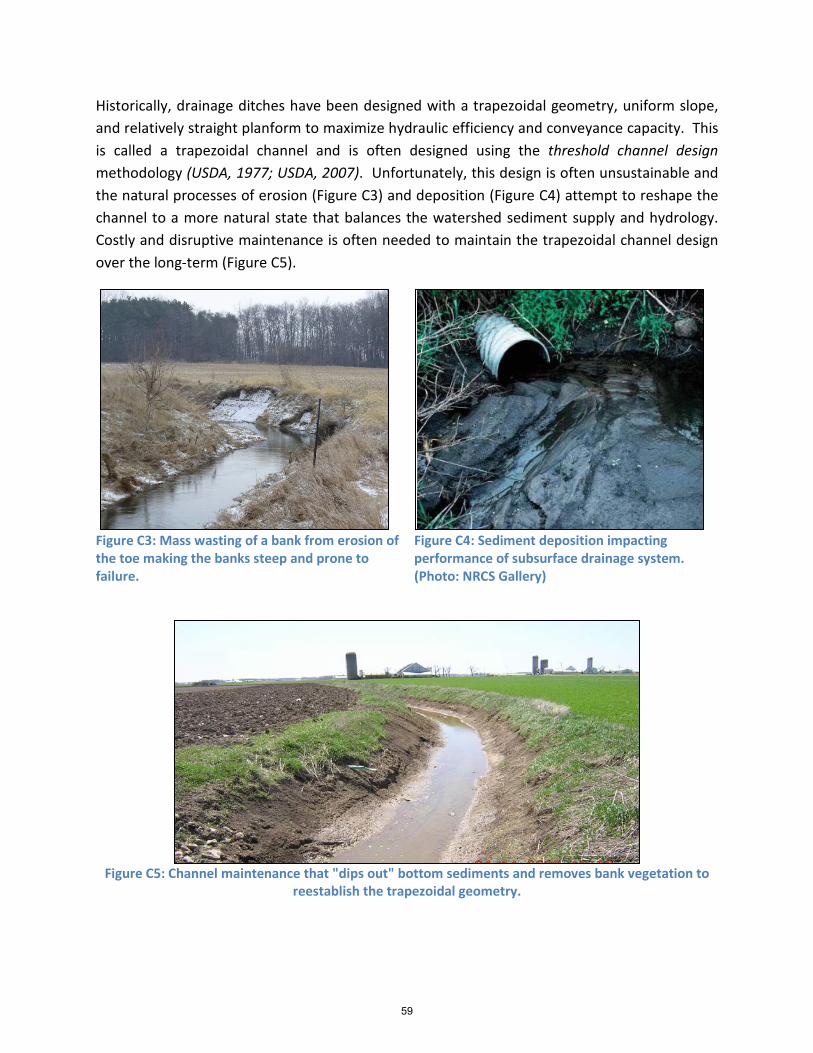
Historically, drainage ditches have been designed with a trapezoidal geometry, uniform slope, and relatively straight planform to maximize hydraulic efficiency and conveyance capacity. This is called a trapezoidal channel and is often designed using the threshold channel design methodology (USDA, 1977; USDA, 2007). Unfortunately, this design is often unsustainable and the natural processes of erosion (Figure C3) and deposition (Figure C4) attempt to reshape the channel to a more natural state that balances the watershed sediment supply and hydrology. Costly and disruptive maintenance is often needed to maintain the trapezoidal channel design over the long-term (Figure C5).
Figure C3: Mass wasting of a bank from erosion of the toe making the banks steep and prone to failure.
Figure C4: Sediment deposition impacting performance of subsurface drainage system. (Photo: NRCS Gallery)
Figure C5: Channel maintenance that "dips out" bottom sediments and removes bank vegetation to
reestablish the trapezoidal geometry.
59

Decades of research and monitoring have revealed impacts associated with traditional channel designs and drainage practices. This knowledge has led to the development of new and innovative management practices which provide the necessary drainage, but may have some positive benefits for water resources. Unfortunately, these practices are relatively new and often not considered in the planning and decision-making processes that guide drainage management and conservation at the local level. The remainder of this section describes these alternative management practices and the tradeoffs amongst them. The sections that follow describe the these practices within the context of the NRCS Conservation Planning Process (CPP) and lay out considerations for the selection of a resource management system (RMS) that includes drainage channel management and the design of two-stage and self-forming channels.
MANAGEMENT OPTIONS FOR DRAINAGE CHANNELS
At any potential project site at least 6 management options for drainage channels should be considered when developing a RMS: 1) do nothing, 2) passive enhancement, 3) threshold channel design, 4) two-stage channel design, 5) self-forming channel design, and 6) natural channel design. In many cases more than one approach may lead to an acceptable outcome and these practices may need to be implemented in conjunction with other conservation best management practices that enhance or maintain conveyance capacity (e.g. NRCS Conservation Practice Standards 326 (Clearing and Snagging)) and channel stability (e.g. NRCS Conservation Practice Standards 322 (Channel Bank Vegetation), 342 (Critical Area Planting), 382 (Fence), 395 (Stream Habitat Improvement and Management), 472 (Use Exclusion), 484 (Mulching), 578 (Stream Crossing), 580 (Streambank and Shoreline Protection), 584 (Channel Stabilization), and 647 (Early Successional Habitat Development/Management)).
The “Do Nothing” and “Passive Enhancement” do not actively alter channel form. The remaining approaches physically alter the existing channel and the primary differences between the approaches are associated with: A) the space required for implementation; B) how the form of the channel is established; C) the dimension, pattern, and profile of the channel; 4) what measures are taken to stabilize the system; and D) cost. The approach selected will depend on a variety of factors based on site specific information and project goals including but not limited to: a real or perceived problem being caused by the system; a desire or need to enhance the system to provide water quality and/or ecosystem services; available funding; meeting any applicable state or federal regulations; site-specific conditions; willing landowners; needs to reduce flooding or erosion; promoting agriculture, development or industry; protecting native species and habitats; and legal requirements. The management approaches are described briefly in the sections that follow. Do Nothing - this approach involves simply leaving the channel in its current state. It is common for channels to go through a period of stabilization after construction or a
60

maintenance activity. Allowing these adjustments to occur can help channels achieve a stable form and recover some level of ecological services while in many cases providing adequate drainage. Generally, if the system is not causing a problem, the Do Nothing approach should be considered. This may be a particularly useful strategy in channels that have predetermined maintenance regimes that landowners pay for through regular tax assessments. In many cases, the channels may perform well in terms of drainage and ecological function, but maintenance is undertaken simply because landowners have paid for it and it is on a prescribed maintenance schedule. Indiscriminant maintenance may lead to loss of some ecological services while only providing a marginal and temporary improvement in drainage and thus may be a poor investment of landowner or taxpayer resources. An example of a system that was functioning well for drainage, but was “cleaned out” due to a scheduled maintenance activity is provided in Figures C6 and C7. The Do Nothing approach would have cost nothing to implement and resulted in substantial savings to landowners while the drainage benefit was likely small and temporary.
Figure C7: The same ditch seen in Figure 6 after the maintenance activity.
Passive Enhancement - this approach involves stopping activities that cause degradation or prevent recovery and allowing natural processes to aid the channel system in recovery. In highly modified channel systems, passive enhancement might include livestock fencing, purchasing conservation easements, invasive species removal, native vegetation planting, and establishing no-mow zones. Although passive approaches may have positive effects, the approach may not be viable for low-energy channels that have been so degraded that recovery can take decades or longer or where accelerated erosion of high banks is severe and may
Figure C6: A section of ditch in Minnesota prior to a maintenance activity.
61
impact sensitive downstream resources. This approach requires little to no engineering input, can be relatively inexpensive, and can greatly enhance some impaired ecosystem functions. Threshold Channel Design and Maintenance - this approach is the traditional, trapezoidal design (see Figure C7 above) suitable for use in rigid boundary systems where erosion of the channel should be minimal for flows below the design discharge. A threshold channel should also transport the sediment load supplied without significant aggradation of the channel bed. In some systems, regular maintenance to remove bank vegetation, clean out bed sediments, or reconstruct the channel boundary is often needed to maintain a stable channel with adequate conveyance capacity. In most cases this approach provides few if any water quality or ecological services. However, in some cases the approach could provide a water quality benefit where there is correct disposal of sediments with high agrichemical or nutrient loads.
Two-Stage Channel Design - this approach is essentially a floodplain construction practice. First, it leaves in place any silt bars or benches that have formed within the confines of the channel and expands the floodplain at the bench elevation (Figures C8 and C9), if additional conveyance capacity is needed. The benches form through natural processes and confine low-flows within the larger drainage channel transporting fine sediments and providing stability to the channel sideslopes. The resulting channel form is more likely to maintain balance between sediment supply and transport and reduce the need for maintenance over time. In a two-stage channel system (Figure C10), the first stage includes the channel bed up to the floodplain bench elevation. This first stage is also referred to as the inset channel or a channel within the channel. The second stage extends up from the floodplain bench to the field. The second stage is typically designed to contain a certain size (i.e. recurrence interval) storm event without flooding into the adjacent fields. Typically, benches on each side of the inset channel will constructed to be 1 to 2 times the top width of the inset channel; where the inset channel top width is determined from an appropriate regional curve of bankfull dimensions.
62

Figure C8: A tributary channel to Bull Creek in Wood County, OH during two-stage channel construction.
Figure C9: Crommer Ditch two-stage reach approximately 6-years after construction.
Figure C10: An annotated photograph of a two-stage channel depicting the first and second stages.
Self-forming Channel Design - this approach establishes the initial conditions upon which a channel and floodplain system will develop over time. It involves excavating the channel bed to an over-wide width and allowing natural processes to develop bars, benches, and an inset channel that is stable and sustainable by natural processes (Figures C11, C12, and C13). The self-forming channel design, in effect, is creating a valley without a floodplain, which results in the spreading of channel flows at low flow rates. Herbaceous vegetation quickly establishes in the bed of the channel, which promotes sediment deposition that forms the floodplains. One of the main benefits of this approach is that it allows space for the system to self-organize to a form that fits to the existing watershed and valley conditions. Depending on these conditions,
1st Stage
2nd Stage
63

the approach may result in a well-defined channel or may represent more of a wetland stream system. Another benefit is that the benches form from sediment and associated pollutants (e.g. nutrients, pesticides, etc.) that would otherwise be transported downstream and therefore is acting as both a sediment and pollution sink. This sink occurs at an accelerated rate in the early stages of succession and diminishes to natural rates as the benches develop and establish a two-stage system over time. Locations where the self-forming approach is suitable include low gradient channels that are not prone to incision; channels transporting low quantities of coarse bed material, where vegetation will be vigorous and unlimited; where in-stream habitat and biota already might not be achieving their attainment status; or where early successional habitat is encouraged.
Figure C11: Self-formed stream at the tributary to Muddy Creek near Kansas, OH. Photograph is shortly after construction.
Figure C12: Self-formed stream at the tributary to Muddy Creek near Kansas, OH. Photograph is 1-year after construction.
64
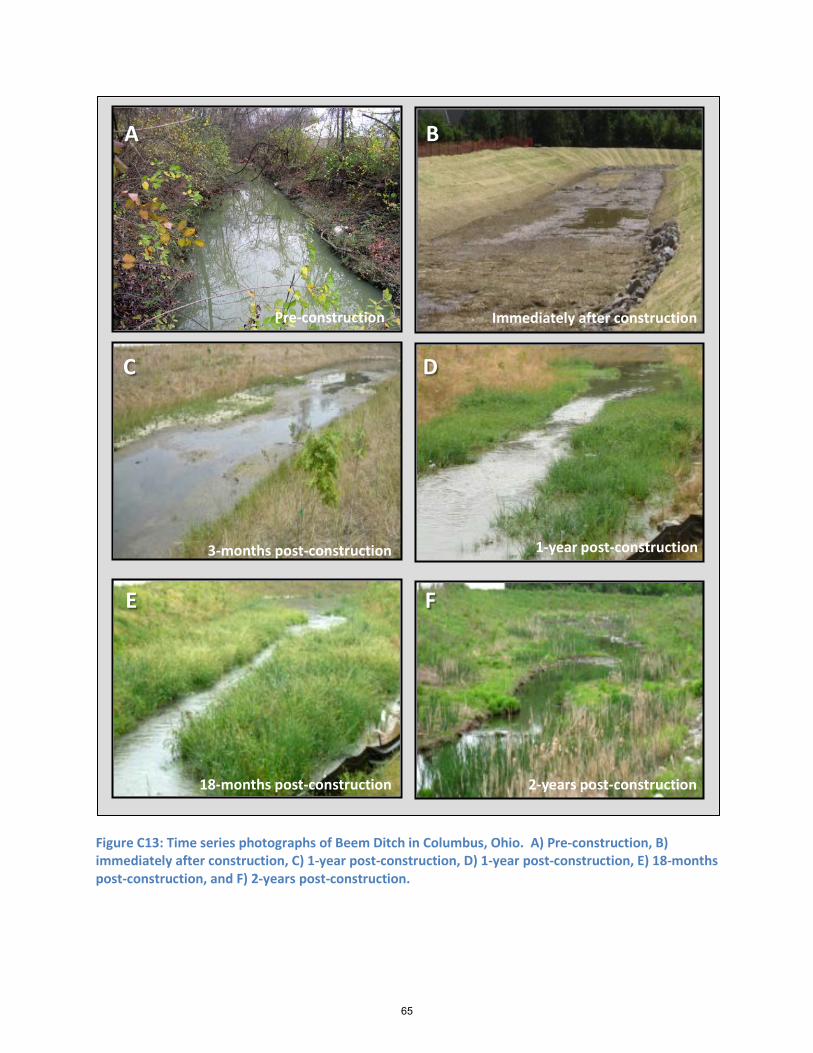
Figure C13: Time series photographs of Beem Ditch in Columbus, Ohio. A) Pre-construction, B) immediately after construction, C) 1-year post-construction, D) 1-year post-construction, E) 18-months post-construction, and F) 2-years post-construction.
A B
C D
E F
Immediately after constructionPre-construction
3-months post-construction
18-months post-construction
1-year post-construction
2-years post-construction
65

Natural Channel Design - this approach involves construction of the channel itself and typically the floodplain. Designs may reconnect channel-forming flows to the floodplain either by raising the bed of the channel to the existing floodplain or by excavating the floodplain down to the channel bed (Figure C14). This approach may include channel shaping such as meanders, riffles, and pools. Structures sometimes are used to improve aquatic habitat, as grade control, and to provide bed and bank stability. These structures include a combination of large rocks and the root masses and trunks from trees. There are numerous methods for determining the criteria for constructed stream design that require a sound understanding of theory and careful consideration of the applicability of the chosen approach to a particular project (Skidmore et al., 2007). The natural channel design approach may be better suited to sites that have stabilized from past disturbances, where past and future land use change is well-known, or where adequate knowledge of sediment transport and fluvial processes are well understood (Nagle, 2007; Niezgoda and Johnson, 2005; Montgomery and MacDonald, 2002).
Figure C14: A natural channel design during construction.
66

THE NRCS CONSERVATION PLANNING PROCESS
USDA-NRCS has a well-established 3-phase, 9-step conservation planning process (CPP) that guides the conservationist through the development and implementation of a RMS. It is not the purpose of this document to present extensive detail on the CPP as that information is provided in Part 600 of the National Planning Procedures Handbook, but the remaining document is structured according to the USDA-NRCS CPP. More specific guidance on the application of the CPP to channel projects is provided in Chapters 2 and 4 of the USDA-NRCS National Engineering Handbook Part 654. The 3 phases of the CPP include: 1) data collection and analysis, 2) decision support, and 3) application and evaluation. These phases essentially allow the conservationist to understand resource problems and opportunities, understand potential solutions, and understand the results. The phases and steps (Table C1) of the CPP and their interrelationships are depicted in a conceptual diagram (Figure C15) that illustrates the dynamic nature of the CPP. Steps early in the process inform latter stages and may need to be revisited as the process progresses and knowledge gaps are identified, new knowledge is developed, and/or project objectives shift. While the CPP is presented sequentially here, linkages to previous and subsequent steps in the process are highlighted and discussed.
Table C1: Phases and steps in the USDA-NRCS Conservation Planning Process (CPP).
Step no. Step Description Phase I – Collection and analysis (understanding problems/opportunities)
1 Identify problems and opportunities 2 Determine objectives 3 Inventory resources 4 Analyze resource data
Phase II – Decision Support (understanding solutions) 5 Formulate alternatives 6 Evaluate alternatives 7 Make decisions
Phase III – Application and evaluation (understanding the results) 8 Implement the plan 9 Evaluate the plan
67

Figure C15: Conceptual diagram of the USDA-NRCS Conservation Planning Process (CPP). (Source: USDA-NRCS National Engineering Handbook Part 654 (Chapter 2; Page 5)).
Step 1: Identify Problems and Opportunities
Problem identification is a crucial step of the planning process, yet it often receives inadequate attention and unsatisfactory project outcomes typically can be attributed to poor understanding of the factors and processes impacting the resource. Good planning normally begins by clearly identifying any real or perceived problems of stakeholders, understanding potential constraints, and recognizing opportunities. Common problems that initiate channel construction or maintenance projects include a need to relocate an existing channel, bank instabilities (Figure C16), excessive sediment deposition reducing channel conveyance capacity and/or restricting subsurface drainage outlets, or inadequate surface drainage capacity (Figure C17). While these projects address drainage needs of landowners for crop production and land development projects, channel projects are more frequently being completed to enhance water resources and protect downstream resources and these goals should also be considered in the planning, decision-making, and management processes.
68

Figure C16: Bank failure threatening an agricultural field in Indiana.
Figure C17: Inadequate drainage capacity. (Source: NRCS Photo Gallery)
Thorough problem identification will involve: 1) identification of all relevant stakeholders, 2) stakeholder interaction and engagement, and 3) assessment of stakeholder tolerance to risk. Early in the process, meetings with the landowner(s) should be conducted to identify and document any real or perceived issues with drainage function, channel stability, water quality, or other resource concerns. Other stakeholders including local agencies, upstream or downstream communities, watershed groups, and others should be engaged throughout the process as needed and appropriate. These entities can aid in the identification of problems beyond individual sites or channel reaches. At this time, it is also important to gauge landowner willingness to adopt alternatives to the traditional management practices (i.e. trapezoidal channel design and maintenance). Some education may be required as alternative management designs (e.g. two-stage and self-forming channels) are relatively new and many stakeholders are unfamiliar with the concepts, their costs, potential positive and negative impacts, and tradeoffs amongst management strategies. Finally, any potential constraints such as federal, state, and local regulations (e.g. protecting endangered species, flood protection, etc.) that may impact the selection of a RMS should be identified and documented at this time, if possible and practical.
Outcome of Problem Identification
The primary result of this step should be a comprehensive understanding of local and watershed resource concerns of stakeholders and any constraints that may be limiting or opportunities that may be beneficial. Findings should be documented in sufficient detail to be revisited and revised, as needed, throughout the project period.
69

Step 2: Determine Objectives During this step, the conservationist should work with stakeholders to clearly define and
document resource goals and objectives on, and off-site of, the project reach. Often stakeholders have competing goals and comprises may be needed to balance various stakeholder objectives. As new information becomes available in subsequent steps of the planning process, it may be necessary to revise project objectives iteratively. A preliminary set of project goals and objectives may not be set until the completion of Step 4 (Analyze Resource Data) and may be further revised as alternatives are evaluated (CPP Step 6). Good objective statements will be: 1) specific, 2) realistic, 3) achievable, and 4) measurable. Common objectives of channel projects are to address bank instability and excessive erosion, prevent flooding, protect infrastructure and land, protect water supplies, enhance aquatic and riparian habitat, and improve or protect water quality.
Outcome of Determine Objectives
The outcome of this step is a documented list of stakeholder objectives.
Step 3: Inventory Resources The primary purpose of this step is to document baseline conditions and develop datasets
to assess the existing channel system. The data will also be used as a basis for design (CPP Phase II). The inventory and analysis step that follows may be completed concurrently and the outcomes will allow for a more complete and refined definition of resource problems and identification of opportunities described in previous steps (CPP Steps 1 and 2).
PRELIMINARY DATA COLLECTION AND INVENTORY
An initial site visit and watershed evaluation should be conducted to identify and confirm any resource concerns and to qualitatively evaluate conditions of the channel and surrounding landscape. Site evaluations typically include walking all reaches in an area of concern and documenting problems, making rough measurements of channel dimensions (e.g. widths and depth), identification and measurement of any fluvial features (e.g. existing floodplain benches and a stable bankfull channel (i.e. inset channel) that might be present, identifying and documenting tile outlets and areas in need of erosion control, and overall vegetative condition. Photographic documentation (Figure C18) and mapping of resource problems on maps or aerial images (Figure C19) may also be useful during the inventory process.
70

Figure C18: Photographic documentation collected during preliminary data collection phase.
Toe Scour
Excessive Sedimentation
Channel Top Width
Channel Bottom Width
Depth
71

Figure C19: Planform map documenting location of resource concerns and existing structural features.
In addition to reach-level data, preliminary data on the watershed should be obtained.
Watershed data should be collected as the channel and its watershed are inextricably linked and management activities and instabilities outside the project reach may impact the site in the future. Reconnaissance or “wind shield” surveys typically involve a driving tour of the contributing watershed area and inspection of channel reaches downstream from the project reach. It is recommended that a GIS map which includes roadways and watershed boundaries draped over recent aerial imagery is developed and used in the field to spatially document any relevant information. Areas of significant land cover or land use change should be noted on the map to identify potential alterations to watershed hydrology (e.g. urbanization, deforestation, etc.) that might impact the project design. Whenever possible, photographic documentation with geospatial location information is recommended to document conditions.
In addition to an inventory of current conditions, the conservationist may want to contact other local agencies that may be able to provide additional insights on watershed history and future development plans for an area which could impact selection and design of a RMS. Preparation for the windshield tour may include review of historical imagery (e.g. Google Earth) to assess land cover and land use changes over time. During the windshield survey it is also
Gulley Erosion
Erosion Control Structures (Rock Chutes)
Bank ErosionRip Rap
8’ Corrugated Steel Culvert
72
recommended to stop at points along roads where channels intersect and qualitatively assess their condition and the presence or absence of any geomorphological features (e.g. inset bankfull channel) that might have formed within the larger channel. This assessment will provide locations of sites that may be used in the development of hydraulic geometry relationships for the watershed which are needed to assess baseline conditions and during the design process. The watershed reconnaissance also provides an opportunity to identify unstable channels upstream from a project site that may supply excessive sediment loading to a channel reach or unstable downstream channels may result in instability (e.g. a headcut) that migrates upstream with potentially destabilizing effects on the project reach.
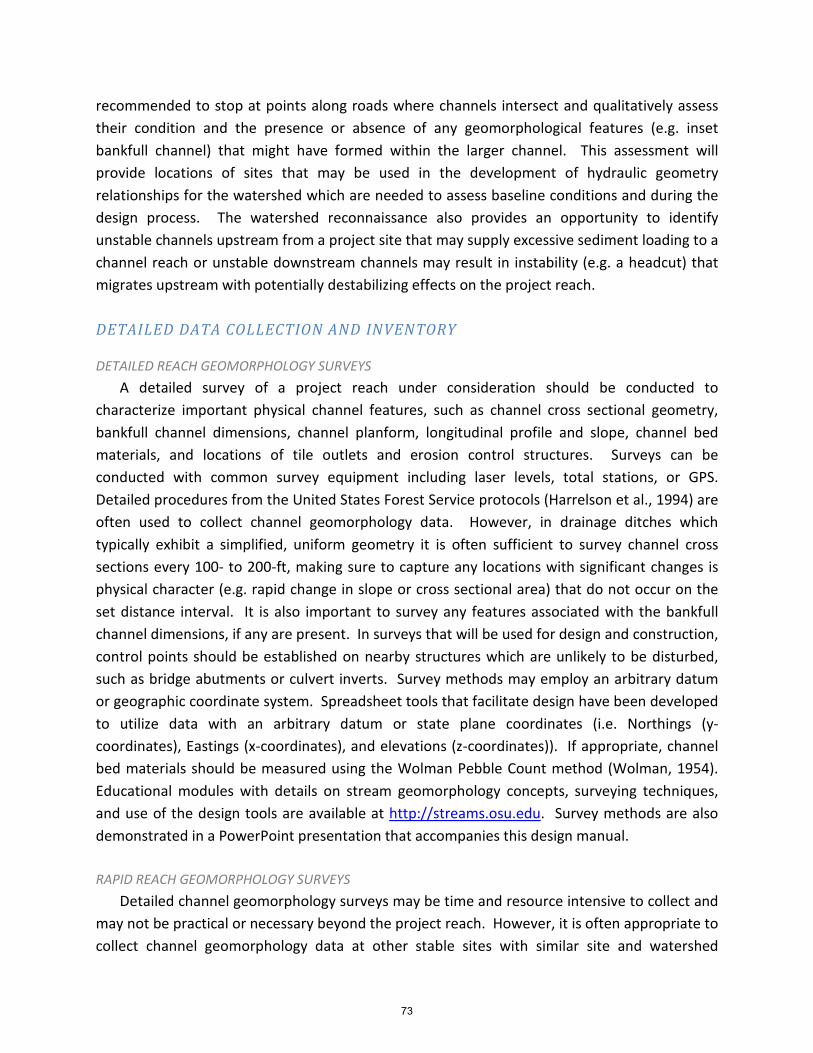
DETAILED DATA COLLECTION AND INVENTORY
DETAILED REACH GEOMORPHOLOGY SURVEYS A detailed survey of a project reach under consideration should be conducted to
characterize important physical channel features, such as channel cross sectional geometry, bankfull channel dimensions, channel planform, longitudinal profile and slope, channel bed materials, and locations of tile outlets and erosion control structures. Surveys can be conducted with common survey equipment including laser levels, total stations, or GPS. Detailed procedures from the United States Forest Service protocols (Harrelson et al., 1994) are often used to collect channel geomorphology data. However, in drainage ditches which typically exhibit a simplified, uniform geometry it is often sufficient to survey channel cross sections every 100- to 200-ft, making sure to capture any locations with significant changes is physical character (e.g. rapid change in slope or cross sectional area) that do not occur on the set distance interval. It is also important to survey any features associated with the bankfull channel dimensions, if any are present. In surveys that will be used for design and construction, control points should be established on nearby structures which are unlikely to be disturbed, such as bridge abutments or culvert inverts. Survey methods may employ an arbitrary datum or geographic coordinate system. Spreadsheet tools that facilitate design have been developed to utilize data with an arbitrary datum or state plane coordinates (i.e. Northings (y-coordinates), Eastings (x-coordinates), and elevations (z-coordinates)). If appropriate, channel bed materials should be measured using the Wolman Pebble Count method (Wolman, 1954). Educational modules with details on stream geomorphology concepts, surveying techniques, and use of the design tools are available at http://streams.osu.edu. Survey methods are also demonstrated in a PowerPoint presentation that accompanies this design manual.
RAPID REACH GEOMORPHOLOGY SURVEYS
Detailed channel geomorphology surveys may be time and resource intensive to collect and may not be practical or necessary beyond the project reach. However, it is often appropriate to collect channel geomorphology data at other stable sites with similar site and watershed
73

characteristics to the project reach in the region. These data are used to develop hydraulic geometry relationships called regional curves that are used in the design process to predict the dimensions of a bankfull channel that is likely to be stable and sustainable at a site. Development of a regional curve involves the measurement of bankfull channel dimensions at multiple locations across a range of drainage areas. Bankfull dimensions are then plotted as a function of drainage area on a log-log scale and fit with a power function regression line (e.g. Figure C20). A rapid method to collect data for the development of regional curves would typically involve the selection of representative cross sections at many stable sites and either surveying the cross sections or simply measuring the bankfull channel width and estimating the mean depth from multiple measurements of depth across the inset channel (Figure C21). Bankfull dimensions are then plotted against the drainage area of the site. In many cases a few measurements might be made and compared to an existing regional curve to determine consistency. Additional in depth information on regional curves is provided in Section 654.0905 of Chapter 9 in the National Engineering Handbook Part 654.
Figure C20: Regional curves for the Portage River watershed.
74

Figure C21: Rapid measurement of bankfull channel width.
BED, BENCH AND BANK GEOTECHNICAL PROPERTIES
In some cases, additional measurements may be needed to assess the stability of the existing channel. These measurements are made to determine the resistance of the bed and bank soils to hydraulic erosion and geotechnical failures, to estimate sediment transport, and to approximate water movement through banks. Assessment techniques that could be used include: 1) inspection of exposed soils along channel banks and bottom, 2) digging soil pits, 3) extraction of soil cores (Figure C22) to test (e.g. unconfined compression tests) in the laboratory, 4) in situ shear tests (e.g. Iowa Borehole Shear Method; Figure C23), and 5) bed, bench and bank erodibility tests (e.g. non-vertical submerged jet tests). Other methods of investigation are acceptable, but all methods should be conducted by qualified personnel.
Inspection of exposed soils should be undertaken by a soil scientist and soils borings should be analyzed by qualified laboratories. Soils properties that may be useful for judging stability include textural class, particle size distribution, soil consistency (e.g. liquid and plastic limits), void ratio, unit weight, and shear strength (e.g. unconfined compression tests). Details on the methods and sampling designs to assess channel stability are provided in Chapter 3 of USDA-SCS Technical Release 25 (1977) and Chapter 8 of the National Engineering Handbook Part 654.
75

Figure C22: Soil core extracted for inspection and lab analysis to determine unconfined compression strength.
Figure C23: Iowa borehole shear test to make in situ measurements of bank geotechnical properties.
Existing benches provide useful information on fluvial processes and/or bank stability; however, they require careful evaluation. Of particular importance is to determine if the benches are due to deposition of sediment transported by discharge in the system or due to slumping/sluffing of the banks. If they are due to bank failures there is sometime a separation between the benches and the sides of the banks. Also benches associate with bank failures often have a very uneven surface that might be located higher in the ditch than the bottom third of the ditch depth. If the benches are associated with mass failure of the banks it is particularly important to identify the causes of the failures. In some cases benches formed by fluvial processes are unstable and scour or wash out during large events. Instability in these benches might be associated with high tractive forces, or high base flows, and an inability to naturally build to a stable geometry. HYDROLOGY DATA COLLECTION
Measurements or estimates of discharge rates and frequency, typically for flows that occur many times annually up to extreme events such as the 100 year discharge, are needed to assess channel geomorphology, hydraulics, sediment transport, and risk. Predictions of discharge are typically made with empirical equations or computer models, but for some projects it may be desirable to collect field data or utilize USGS gage data to evaluate and calibrate discharge estimates at ungaged sites. Field measurements of discharge typically involve measurement of channel form to describe cross sectional flow area and flow velocity measurements which can be used in conjunction with survey data to calculate discharge. Measurements at multiple stages can be used to construct stage-discharge-velocity relationships to check or calibrate open channel hydraulics estimates used in evaluation and design. These methods are described in detail in Chapter 14 of the USDA-NRCS National Engineering Handbook Part 630.
76

OUTCOME OF INVENTORY RESOURCES
The primary outcome of the Inventory Resources step is to document benchmark conditions including information on human considerations, ecological concerns, cultural resources, physical infrastructure, types of management activities and their timing, and detailed site data describing the conservation management unit (CMU).
Step 4: Analyze Resource Data Analysis of resource data should focus on determining the current status of the channel and
riparian zone and clearly defining resource conditions, including limitations to their use and potential uses. This step also serves as the basis needed to formulate and evaluate RMS alternatives (CPP Steps 5 and 6). ASSESSMENT OF EXISTING CHANNEL CONDITION
Channel condition is influenced by geology, topography, hydrology, land use, soils, climate, management activities, and other abiotic and biotic factors. The interactions amongst these factors generate runoff and channel flow which exerts forces (i.e. the driving forces) on channel boundaries which have some ability to resist those forces. Channel form develops and adjusts to changes in these driving and resisting forces seeking a balance between sediment supply and transport. Channels that balance supply and transport are said to be in a state of dynamic or quasi-equilibrium and are stable or exhibit normative or acceptable rates of change. Channels that transport more sediment than supplied are failing through the process of erosion either vertically (i.e. channel incision) or laterally (i.e. bank failures and mass wasting) and the primary mode of failure depends on the resistance of the bed and bank materials to erosion. Channels can also fail through excessive deposition that negatively impacts a resource and does not result in a more sustainable and stable form in a reasonable timeframe; however, aggrading streams are typically viewed as being in a state of recovery characterized by the development of point bars and floodplain benches. In many systems recovery may take a few years, many decades, or even centuries depending on site and watershed characteristics, climatic conditions, and human management practices.
A useful starting point in the development of a RMS for a drainage channel is to understand its current condition. Knowledge of the current state will aid in the determination of potential management options that are likely to succeed and meet project goals. For example, a channel that is actively failing is likely to further incise or widen before recovery takes place. If this does not impact adjacent and upstream land uses and the downstream effects of sediment and associated nutrients are acceptable then a passive enhancement approach may be an
77

acceptable management choice. If these impacts are unacceptable, a more active management approach which mitigates or eliminates stressors (e.g. reduces runoff rates and volumes from the landscape), stabilizes the channel, and/or promotes recovery should be implemented.
In natural systems subject to a great deal of variability, such as channels, there is often considerable uncertainty in making predictions of channel conditions and process rates difficult. Therefore, several researchers (Powell et al., 2007a,b; Montgomery and MacDonald, 2002) have recommended the use of multi-factor “weight-of-evidence” approaches to assess channel condition. Any suitable method can be used to make an appropriate assessment methods will vary be region. The following factors have been shown to be useful for assessment in low-gradient channels of the Midwestern US (Powell et al., 2007a,b): 1) a comparison of bankfull channel dimensions to expected values from regional curve relationships, 2) a comparison of channel bed materials to the estimated particle size at incipient motion using tractive force theory (Ward and Trimble, 2004), 3) the recurrence interval of the bankfull discharge, 4) an estimate of bank stability, and 5) a comparison of the existing bankfull channel depth to the theoretical bankfull elevation based on effective discharge theory. Additional details on the weight-of-evidence assessment procedure are provided in Powell et al., 2007a,b).
OUTCOME OF ANALYZE RESOURCE DATA
The primary outcomes of the Analyze Resource Data step will be: 1) an analysis of all inventoried resources, 2) determination of channel equilibrium state, 3) environmental and cultural evaluation data, 4) identification of causes of resource concerns, and 5) a complete statement of project objectives (i.e. step 2 is essentially finalized).
Step 5: Formulate Alternatives This step focuses on the development of alternatives that will meet client/stakeholder
objectives, solve relevant problems, take advantage of any opportunities, and avoid negative consequences from occurring. At this point, a broad spectrum of practical alternatives should be developed with input from the client/stakeholders. Engaging the end user in the process typically leads to better solutions and greater acceptance.
When developing a RMS for a channel and riparian corridor the conservationist has a suite of best management practices to address resource concerns. USDA-NRCS (2007) has developed a conceptual framework (Figure C24) which defines a continuum of zones from channel to uplands. Chapter 4 (specifically Tables 4-4, 4-5, and 4-6) of the National Engineering Handbook Part 654 contains extensive guidance on the selection of best management practices, with references to NRCS Conservation Practice Standards, for a range of resource concerns in each of the zones. It is not the purpose of this document to supplant that guidance, but to
78

incorporate additional practices into existing guidance where appropriate. The following proposed modifications focus solely on the addition of two-stage and self-forming channel designs. The proposed modifications are highlighted in Table C2. However, additional modifications to this guidance and the Open Channel Conservation Practice Standard (582) could include other practices, such as natural channel design. Attachment of an active floodplain to a bankfull channel is a common component of the natural channel design approach and forms two-stage systems. Allowing the construction of an appropriate meandering bankfull channel would be a simple and appropriate addition to the Open Channel Conservation Practice Standard (582). However, the inclusion of woody vegetation on the floodplain, adding hydraulic control structures, and bioengineering of the banks (beyond using grass) did not fall within the scope of the current project. This guidance is desirable and might best be developed by scientists, engineers, and practitioners with experience with natural channel design applications in agricultural ditches. OUTCOME OF FORMULATE ALTERNATIVES
The primary outcome of this stage is a description of the RMS alternatives available to the client/stakeholders.
79

Figure C24: Conceptual cross section of management zones. The zones are described in detail in Chapter 4 of the USDA-NRCS National Engineering Handbook Part 654. (Source of Figure: USDA-NRCS National Engineering Handbook Part 654; Figure 4-6)
80

Table C2: Modifications to Tables 4-4, 4-5, and 4-6 from the National Engineering Handbook Part 654. Revisions highlighted in bold and italics. Page (Ch. 4 NEH 654)
Impairment
Zones
Primary NRCS Practice Standards
Considerations and effects
4-10 Unbalanced channel sediment transport and deposition; unstable channel bed and/or gradient
Bed, toe Open Channel (582) Various techniques including two-stage channels, self-forming channels, and/or channel meander reconstruction at a site will reconfigure the bed and bank topography channel and/or floodplain form and influence the extent of overbank and transitional zones and related soil moisture and the selection of vegetation species
4-10 Accelerated bank erosion and instability
Bank, toe Open Channel (582) Modify channel and/or floodplain form using various techniques including two-stage, self-forming, and natural channel design to reduce shear stress at the bank toe interface. May be combined with Channel Bank Vegetation (322), Streambank and Shoreline Protection (580), Clearing and Snagging (326), Critical Area Planting (342), or Mulching (484).
4-14 Obstructions or channel configurations affecting flow capacity or fish passage
Bed, toe, and bank
Open Channel (582) Various techniques including two-stage channels, self-forming channels, and/or channel meander reconstruction at a site will reconfigure the bed and bank topography channel and/or floodplain form and influence the overbank extent, soil moisture and vegetation species. Modifying an existing channel to a self-forming geometry addresses flow capacity, but might negatively impact aquatic biology during early stages of development.
4-15 Lack of early successional habitat for target wildlife
Bed, bank, toe, overbank, and transitional
Open Channel (582) Implementation of the self-forming channel design initiates the development of early successional habitat
81

Step 6: Evaluate Alternatives To provide stakeholders with sufficient information to select a channel management
practice as part of a RMS, each of the potential solutions must be evaluated thoroughly to assess channel stability, costs, and potential benefits and impacts. All projects are unique to some degree and it is up to the conservationist to select and/or modify an appropriate approach when evaluating alternatives. The approach selected should be based on knowledge of the existing system, underlying processes, and sound engineering principles. A general recommended starting point for designing two-stage and self-forming channels is as follows: Step 6.1: Develop an initial design. Step 6.2: Assess stability of proposed channel. Step 6.3: If design meets stability checks go to step 5. Otherwise, redesign channel dimensions. Step 6.4: If redesign does not satisfy stability checks or meet project requirements/constraints
integrate temporary and/or permanent erosion control and reassess stability. Step 6.5: Estimate costs, benefits, impacts, and long-term maintenance needs. Each of the steps is described in greater detail in the sections that follow and the Channel Design spreadsheet tool can be used as an aid in the evaluation process.
Step 1 – Initial Design
For a self-formed channel the primary design variables are slope and width. Most channel projects in agricultural drainage ditches will maintain the current bed slope leaving width as the only design variable. The width of the inset channel that is expected to develop as the self-forming channel evolves over time will be estimated using a hydraulic geometry relationship. The hydraulic geometry relationship that is selected for design should be representative of the site and watershed conditions. Sites used in its development should not differ significantly from the project site in terms of hydrology, hydraulics, and sediment transport. Once an appropriate relationship is developed and an expected bankfull channel width is estimated and the minimum width of the self-forming channel bottom should be at least 3 times that value. A minimum of 3 times the bankfull width is recommended as floodplain benches are less likely to establish and remain stable below this threshold.
In a two-stage channel the primary design variables are slope, width, and bankfull channel depth. Once again slope will most likely be maintained to the existing channel bed. The depth of the inset channel will be determined from field measurements of the bankfull channel depth and estimates from the regional hydraulic geometry relationships. It is also unlikely the overall
82

ditch depth (from channel bottom to the field elevation) will change and thus overall ditch depth typically will not be a design variable that is manipulated significantly. Therefore the width of the channel at the bankfull elevation is the primary design variable. Similar to the self-forming channel the minimum width of the floodplain benches should be a minimum of 3 times the bankfull channel width. The width of the benches on each side of the inset channel does not need to be identical but one-sided construction is not recommended. The second stage channel can also be sized to convey a specific design event that conveys discharge without flooding into adjacent fields Step 2 – Assess Stability
There are multiple methods to assess channel stability, but the predominant method used in channels that have been determined to be stable (see step 4) is to estimate whether the proposed design will result in flow velocities and shear stresses that are lower than the current configuration. The basic assumption is that if the existing channel is stable then reducing velocity and shear stresses should only enhance stability.
Additional methods of stability analysis are provided by USDA (2007; Chapter 8). The selection of a method to assess stability depends upon the composition of the boundary materials within the threshold channel. Standard methods for threshold channels include the permissible velocity, allowable shear stress, and allowable tractive power approaches. The allowable velocity approach is appropriate for use in systems with boundary material smaller than sand and the allowable shear stress is appropriate for systems with boundary material larger than sand. If boundary materials do not act as discrete particles the allowable tractive power method is recommended. When the system is alluvial with a mobile boundary under normal flow conditions the conservationist is directed to Chapter 9 of the National Engineering Handbook Part 654 (USDA-NRCS, 2007).
Channel stability will typically be evaluated for a range of conditions. Immediately after construction a bare earth or “unaged” channel will likely be more vulnerable to failure than a vegetated or “aged” channel that develops in the months and years following construction or a channel protected by erosion control. Often the unaged condition will be evaluated for a more frequent design discharge, such as the 10-yr recurrence interval event. The aged channel condition would often be evaluated for the 100-yr or ditchfull design discharge. Design specifications should be outlined in the Open Channel (582) Conservation Practice Standard for the project state or region.
If warranted, the conservationist may determine the need to perform additional stability checks using a range of methods and tools (Table C4). Numerous spreadsheet tools (e.g. Bank Stability and Toe Erosion Model) and numerical models (e.g. HEC-RAS, SAM) are reasonable design aids, well documented, and freely available. Often experience and judgment may be
83

used to estimate some elements of design, such as stable channel sideslopes, when risk of failure is low or the result of a failure is unlikely to cause harm.
Table C4: Links to tools that can be used to aid in the design process. Issue Tool Link
Bank Stability Bank Stability and Toe Erosion Model
http://www.ars.usda.gov/Research/docs.htm?docid=5044
Sediment Transport
Sediment Analysis Methods (SAM)
http://chl.erdc.usace.army.mil/chl.aspx?p=s&a=ARTICLES;67
Sediment Impact Analysis Methods (SIAM)
Integrated into HEC-RAS (see link below)
Flood Routing HEC-RAS http://www.hec.usace.army.mil/software/hec-ras/ Step 3 – Redesign (as needed)
Depending on the outcome of the initial stability analysis it may be necessary to redesign the proposed channel. In both self-forming and two-stage channels the width may be manipulated to meet stability requirements. Widening of the proposed channel will reduce the hydraulic radius, flow velocity, and shear stress at a particular design discharge. However, it will be necessary to develop a design which fits within project constraints. For example, a wider channel may not be acceptable to a landowner trying to minimize land loss to achieve channel stability. In some cases, integration of temporary or permanent erosion control may provide a useful alternative (see Step 4 below).
Step 4 – Erosion control (as needed)
In channels that do not meet stability requirements during the unaged condition, temporary erosion control (e.g. straw mats, geotextiles, etc.) may be installed during construction. For channels that do not meet stability requirements after the channel has aged, grade control structures and bank rip-rap provide a more permanent solution. In some cases, permanent erosion control may be needed intermittently throughout a reach, such as around curves where flow velocities on the outer bends are higher. Both designs will also necessitate the reconstruction of tile outlets and any existing erosion control structures that deliver surface runoff to the channel.
Step 5 – Estimate costs/benefits
After one or more stable design solutions are developed, each should be evaluated to determine costs and estimate potential benefits. In addition to identifying an optimal RMS
84

which best addresses resources concerns, the planner must also consider a broad range of factors which affect the practicality of the design solution. Several factors which must be considered include: 1) construction access and scheduling, 2) safety concerns, 3) availability of construction equipment and materials, 4) pollution control requirements, and 5) legal regulations.
OUTCOME OF EVALUATE ALTERNATIVES
The end outcome of this step is a set of practical and implementable RMS alternatives that are compatible with client/stakeholder objectives. A thorough evaluation of each RMS and the effects and impacts is the basis for decision-making (step 7).
Step 7: Make Decisions In this step the conservationist presents the design alternatives and assists the
client/stakeholders in the selection of a RMS. In the case of an area-wide conservation plan, a public review and comment period may be needed before a final decision is reached. OUTCOME OF DECISION-MAKING
The outcome of decision-making is the final selection of a RMS.
Step 8: Implement Plan Plan implementation involves providing technical assistance to landowners and contractors.
Some relevant issues for channel work may include obtaining permits, funding, assessing land rights, and inspections of as-built practices. Permitting issues for channel work vary by county and state and it is up to the conservationist to determine which requirements need to be satisfied. Often agricultural drainage channels with small drainage areas are exempt from state and federal regulations; however, this should be investigated closely to avoid project delays and potential fines or penalties.
Most drainage contractors will not be familiar with the two-stage and self-forming channel designs and may need some technical assistance and oversight during initial stages of construction; however, the concepts are simple to construct and can be undertaken by drainage contractors experienced in traditional channel construction and maintenance. Key issues involve: 1) excavation of the channel features at the design elevations, 2) proper reconstruction of the tile outlets and placement of any structural erosion control practices, 3)
85
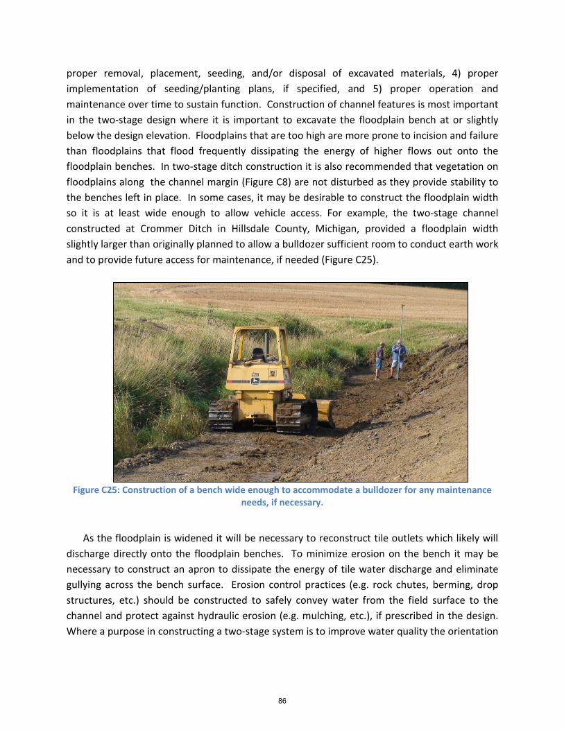
proper removal, placement, seeding, and/or disposal of excavated materials, 4) proper implementation of seeding/planting plans, if specified, and 5) proper operation and maintenance over time to sustain function. Construction of channel features is most important in the two-stage design where it is important to excavate the floodplain bench at or slightly below the design elevation. Floodplains that are too high are more prone to incision and failure than floodplains that flood frequently dissipating the energy of higher flows out onto the floodplain benches. In two-stage ditch construction it is also recommended that vegetation on floodplains along the channel margin (Figure C8) are not disturbed as they provide stability to the benches left in place. In some cases, it may be desirable to construct the floodplain width so it is at least wide enough to allow vehicle access. For example, the two-stage channel constructed at Crommer Ditch in Hillsdale County, Michigan, provided a floodplain width slightly larger than originally planned to allow a bulldozer sufficient room to conduct earth work and to provide future access for maintenance, if needed (Figure C25).
Figure C25: Construction of a bench wide enough to accommodate a bulldozer for any maintenance
needs, if necessary.
As the floodplain is widened it will be necessary to reconstruct tile outlets which likely will
discharge directly onto the floodplain benches. To minimize erosion on the bench it may be necessary to construct an apron to dissipate the energy of tile water discharge and eliminate gullying across the bench surface. Erosion control practices (e.g. rock chutes, berming, drop structures, etc.) should be constructed to safely convey water from the field surface to the channel and protect against hydraulic erosion (e.g. mulching, etc.), if prescribed in the design. Where a purpose in constructing a two-stage system is to improve water quality the orientation
86

of the tile outlets might be modified to allow tile discharges to flow along the benches to increase interaction between bench soils and vegetation.
As in any practice requiring seeding or planting plans, it is necessary to prepare a proper seedbed and provide growing conditions to promote vegetation establishment in a reasonable timeframe. Construction scheduling should be planned in conjunction with field operations of the landowner, but should consider the need to establish vegetation in the channel during appropriate time periods. In the north-central region of the United States, late spring to early fall provides a window of opportunity when flood flows are less likely and conditions support establishment of vegetation before winter conditions set in. For construction that is completed late in the season the conservationist may elect to plant a cover crop such as annual rye or oats that established quickly to protect against high flows in winter or spring. Replanting of the benches and sideslopes may occur the following year or simply allowed to vegetate by volunteering species of plants. OUTCOME OF IMPLEMENT PLAN
The outcome of plan implementation will be a properly installed conservation practice. Proper operation and maintenance plans, if necessary, should be clearly communicated to the landowner or stakeholder group(s).
Step 9: Evaluate Plan Plan evaluation lets the conservationist determine whether the RMS is functioning as
planned and achieving project objectives. Furthermore, it allows the conservationist and opportunity to identify short and long-term operation and maintenance needs to ensure proper function. When results deviate from those anticipated, it allows the conservationist to learn from success and failures and apply adaptive management techniques. This may lead to revisions of future project goals and target values, conservation plans, and conservation practice standards. OUTCOME OF EVALUATE PLAN
The outcome of plan evaluation is to ensure that the RMS is functioning properly and being maintained. It also provides an opportunity to learn from implementation and guide future conservation planning and implementation activities.
87